Food Automation Service Techniques XWIRE-DIRECT Food quality & supply chain monitor equipment. User Manual Letter Size
Food Automation - Service Techniques, Inc. Food quality & supply chain monitor equipment. Letter Size
User manual

Installation Guide
24/7 Toll-Free Technical Support
1-866-840-4271
(from the U.S., Canada and the Caribbean)
Direct, Inc.
www.MySCK.com
SAVE these instructions
for future reference.
SmartDirect 2TM
2© 2007-2009 SCK Direct, Inc. 229-51363 Rev C www.MySCK.com
NOTICES
SCK Direct, Inc. is not liable for any use of product not
in accordance with SCK Direct, Inc.’s installation and
operation instructions.
CLEANING
Using a clean damp cloth, wipe down the
SmartDirect 2 when necessary using a commercial
quality foodservice-approved detergent. DO NOT
IMMERSE.
NEVER use chemical or abrasive cleaners on the
SmartDirect 2.
TOOLS REQUIRED FOR INSTALLATION
Drill Bit: 3/16” if using wall anchors; #50 if
installing into metal
Hammer
Phillips Screwdrivers
TOOLS REQUIRED FOR
TIER 2 PROGRAMMING
Laptop running Microsoft Windows XP/2000
USB Cable
INCLUDED PARTS
Please confirm that these parts have shipped with
your order:
231-60243-01 (GPRS) or 231-60243-03 (Ethernet)
version
229-51363 Installation Manual
229-51364 MAC ID Form
213-50642 Mounting Kit
213-50759-01 Power Supply Mounting Kit
127-66578 Cable for Ethernet Version, 10 foot
If anything is missing, please call 1-866-840-4271
(8:00 a.m. - 5:00 p.m. EST).
BEFORE YOU INSTALL
The SmartDirect 2TM unit should be installed before
installing your SCK SmartSensor(s) (if applicable).
Changes or modifications not expressly
approved by SCK Direct, Inc. could void
the user's authority to operate the equip-
ment.
NOTE: This equipment has been tested and found to
comply with the limits for a Class B digital device,
pursuant to Part 15 of the FCC Rules. These limits are
designed to provide reasonable protection against
harmful interference in a residential installation. This
equipment generates, uses and can radiate radio fre-
quency energy and, if not installed and used in
accordance with the instructions, may cause harmful
interference to radio communications. However,
there is no guarantee that interference will not occur
in a particular installation. If this equipment does
cause harmful interference to radio or television
reception, which can be determined by turning the
equipment off and on, the user is encouraged to try
to correct the interference by one or more of the fol-
lowing measures:
Reorient or relocate the receiving
antenna.
Increase the separation between the equipment
and receiver.
Connect the equipment into an outlet on a cir-
cuit different from that to which the receiver is
connected.
Consult the dealer for help.
SmartDirect 2TM Direct, Inc.
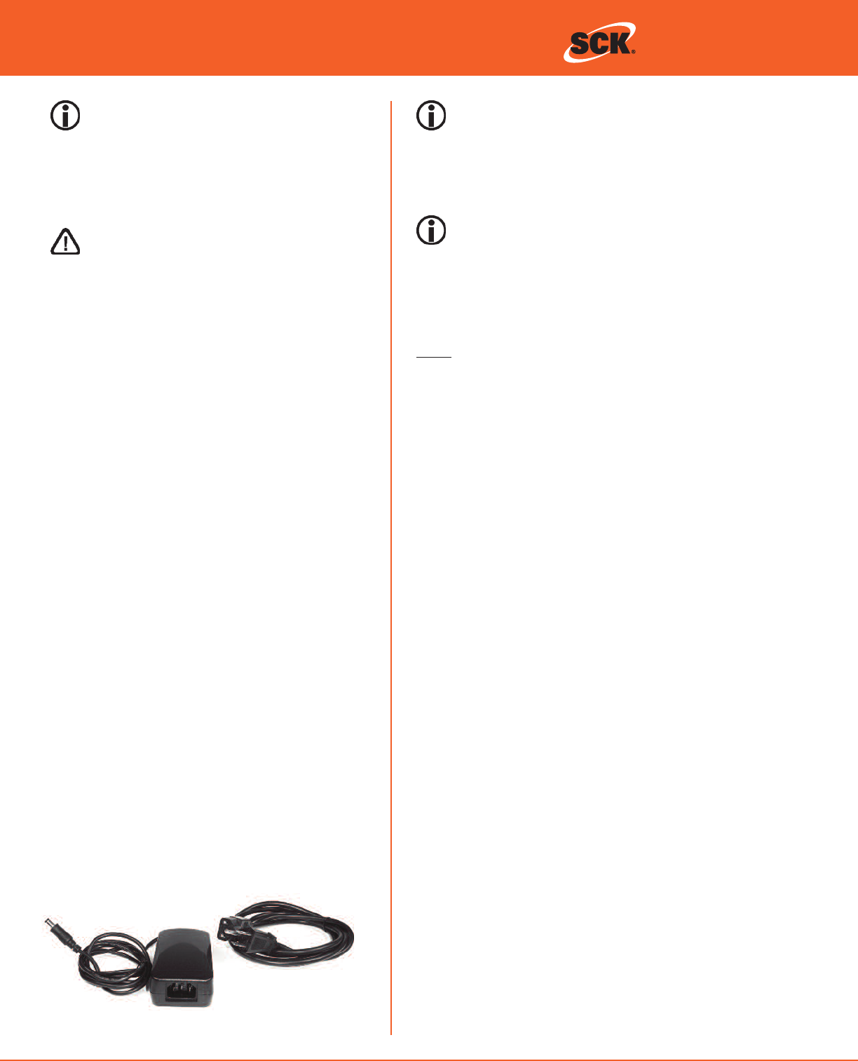
POWER SUPPLY
213-50759-01
POWER CORD OPTIONS
126-10028: Power Cord U.S.
126-10029: Power Cord Euro, Round
126-10030: Power Cord UK, Flat
3
© 2007-2009 SCK Direct, Inc. 229-51363 Rev C www.MySCK.com
INSTALLATION
Location
1. There should be a power outlet within 8 feet of
the mounting location. If using the Ethernet
SmartDirect 2, you will also need Ethernet cables
that are long enough to reach the SmartDirect 2
from your connection. A10-foot Ethernet cable is
supplied.
2. Find an open and easily accessible area to mount
the SmartDirect 2 for the best reception.
If using the GPRS version, screw on and open the
antenna. If using the Ethernet version, go to the
next step.
Mounting the SmartDirect 2
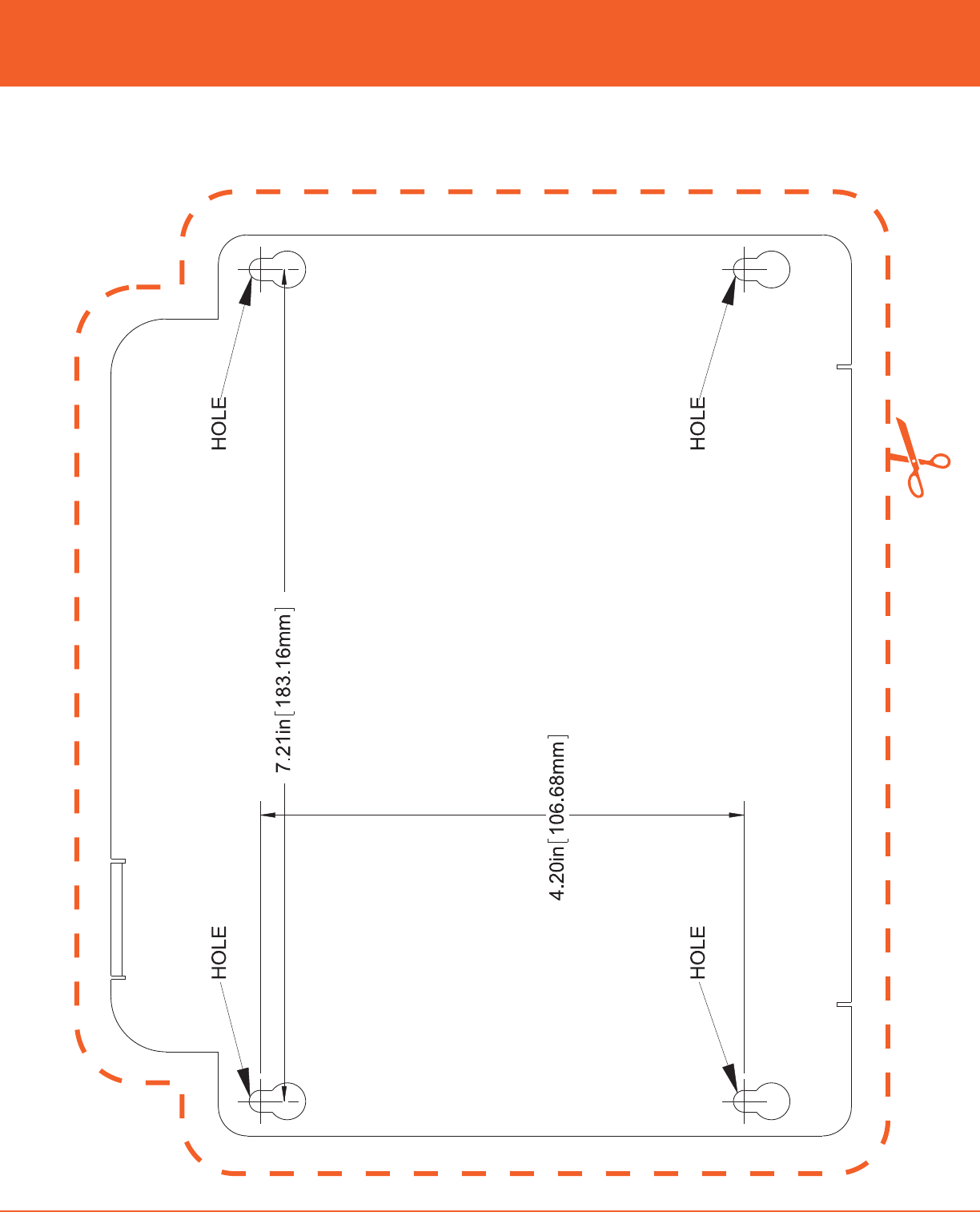
1. Once you have chosen a location, use the tem-
plate guide included with this manual and mark
the locations of the (4) mounting holes. Again,
view the tentative positioning and ensure there
are no location problems.
2a. Drill the (4) holes with the appropriate drill bit, as
defined in Tools Required. If using the four (4)
supplied wall anchors, tap them in using a ham-
mer. If not using the wall anchors screw in the
screws leaving the screw backed off enough to
slide on the SmartDirect 2. Then tighten down
the screws.
2b. If holes cannot be drilled, use the supplied
Velcro. Before mounting, clean the surface with
the supplied alcohol pad. Adhere two pieces of
the Velcro to the back of the SmartDirect 2 and
then two pieces to the mounting surface. Press
the SmartDirect 2 firmly against the mounting
surface and verify it is secure.
Mounting the Power Supply Kit
(part number 213-50759-01)
Once the SmartDirect 2 is installed, the power supply
should be mounted.
1. With the supplied alcohol pad, clean the desired
mounting surface and the one side of the power
supply to which you will be applying the Velcro.
2. Adhere the Velcro to the mounting surface and
the power supply.
3. Press the Velcro side of the power supply firmly
to the Velcro on the mounting surface.
4. Verify the power supply is mounted securely.
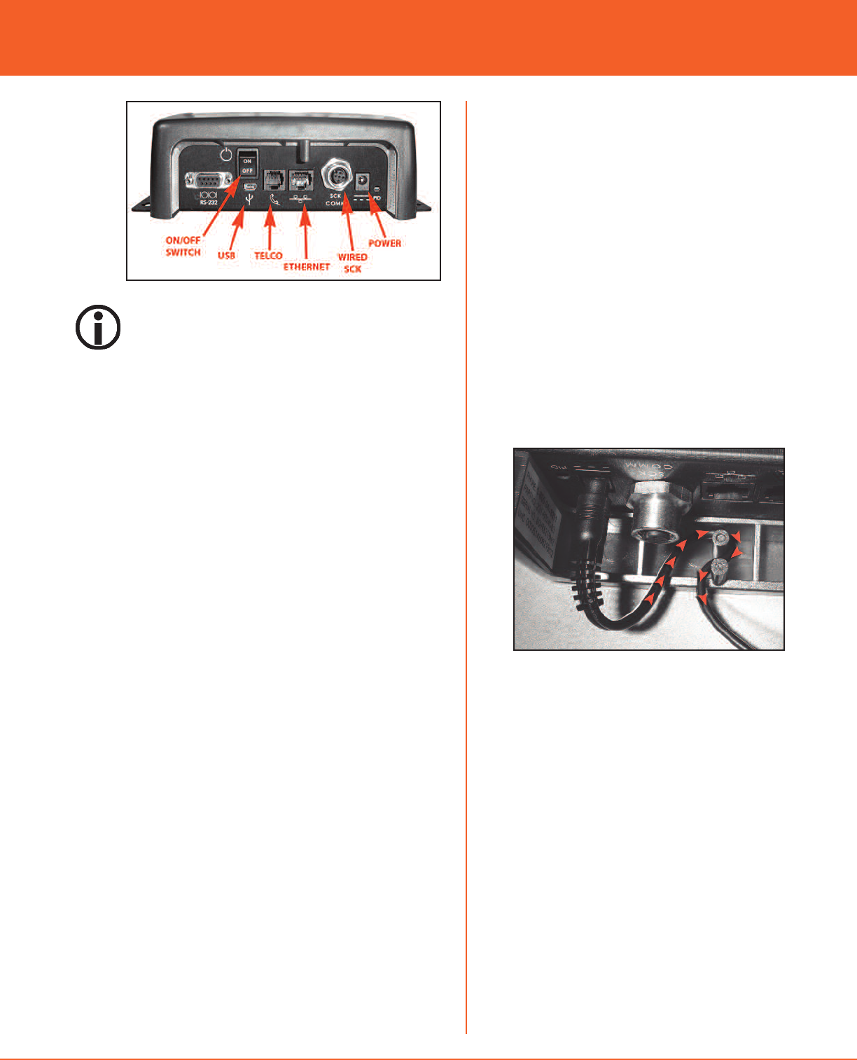
Powering Up and Connecting
1. Insert the power cord into the supplied power
supply. Then plug the power supply into the
SmartDirect 2. Plug the power cord into the out-
let. Turn the power switch to the ON position.
NOTE: ONCE THE POWER SUPPLY IS PLUGGED
INTO THE SMART DIRECT 2 UNIT, WRAP THE
CORD AROUND THE BUILT IN STRAIN RELIEF.
2. At this time if you are using an Ethernet
SmartDirect 2, plug your Ethernet cable into the
port. If you have a GPRS version go to the next
step.
3. When unit is powered up, check the power/sta-
tus LED indicator sequence against the charts on
the next page.
4. Install all other wired and wireless devices.
5. Call the SCK Helpdesk at 1-866-840-4271 (8:00
a.m. to 5:00 p.m. EST) to confirm your system is
up and running.
INSTALL IN AN EASILY ACCESSIBLE LOCATION WHERE
EMPLOYEES CAN ACCESS TO REBOOT THE EQUIPMENT
IF NECESSARY. INSTALLING IN HARD TO REACH
PLACES (FOR EXAMPLE: ABOVE CEILING TILES) IS NOT
RECOMMENDED.
installation guide
4© 2007-2009 SCK Direct, Inc. 229-51363 Rev C www.MySCK.com
SmartDirect 2TM Direct, Inc.
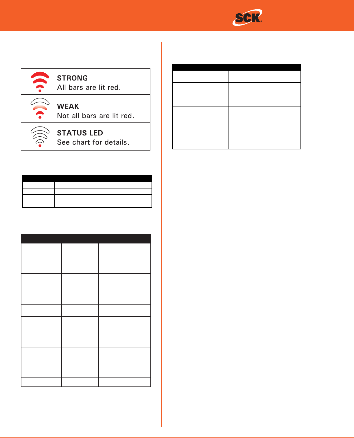
Status LED Chart
Signal LEDs
Troubleshooting / LED Codes
LED Action Description
Strobe effect using all LEDs Device is scanning the channels for
available networks
All LEDs blink on and off
simultaneously every
500ms
Device has detected a multiple SCK
address conflict and is waiting for
resolution (currently participating as
address 30)
All LEDs blink in two short
bursts followed by one
second of off time
The device is connected to network
but not to a FAST control
communicatin
g
SCK.
LEDs alternate being lit in
sequence for a period of
time.
A diagnostic command was issued
to this device to blink the LEDs in a
recognizable pattern for a set
amount of time.
Bars Link Quality
NONE (0) No signal or No messages received
ONE (1) Moderate signal
TWO (2) Good signal
THREE (3) Excellent signal
Signal Strength Indicator
INDICATOR CHARTS
LED Color LED Blink Rate Description
RED Solid On Device is connected as
a router
RED Slow
Device is waiting for
data from its parent
node
RED Very Fast
Device is communicat-
ing with another
device as a
router. Signal bars
should exist.
GREEN Solid On Device is connected as
a coordinator
GREEN Very Fast
Device is communicat-
ing with another
device as a coordina-
tor. Signal bars should
exist.
ORANGE 2 sec ON,
2 sec OFF
Device cannot commu-
nicate with the SCK
device after already
connecting to the wire-
less network.
ORANGE Very Fast Device is initializing.
5
© 2007-2009 SCK Direct, Inc. 229-51363 Rev C www.MySCK.com
installation guide
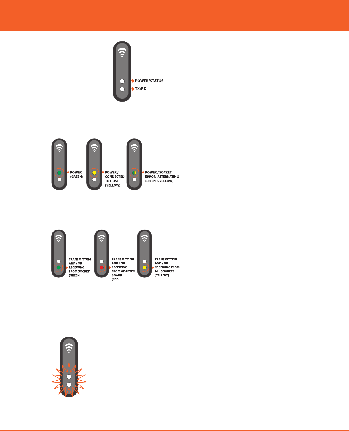
LED Indicators
Power / Status LED
TX / RX LED
SPECIAL LED OPERATION
If all LED lights are flashing rapidly on and off togeth-
er, there is a problem with the external RAM. Please
consult manufacturer.

6© 2007-2009 SCK Direct, Inc. 229-51363 Rev C www.MySCK.com
SmartDirect 2TM Direct, Inc.
This page left intentionally blank.
7
© 2007-2009 SCK Direct, Inc. 229-51363 Rev C www.MySCK.com
MOUNTING TEMPLATE
Use this template as a guide to install the wall mount for your SmartDirect 2. Drawing is to scale.
installation guide

8© 2007-2009 SCK Direct, Inc. 229-51363 Rev C www.MySCK.com
SmartDirect 2TM
This page left intentionally blank.
Direct, Inc.
9
© 2007-2009 SCK Direct, Inc. 229-51363 Rev C www.MySCK.com
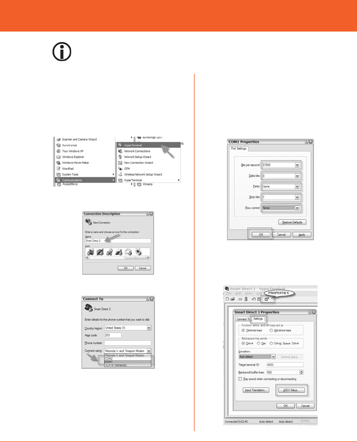
6. Set the port setting to:
Bits per second = 57600
Databits = 8
Parity = None
Stop Bits = 1
Flow Control = None
Then click OK.
7. Click OK, Your Hyper Terminal screen will now be
shown.
8. Click on the PROPERTIES Icon, then SETTINGS,
then click ASCII setup.
SETTING UP COMPUTER TO CHANGE
PARAMETERS USING HYPER TERMINAL:
EXAMPLE (WINDOWS 2000/XP)
1. Click on START.
2. Go to PROGRAMS, then to ACCESSORIES, then
COMMUNICATIONS.
3. Click on HYPERTERMINAL.
4. Name the connection SmartDirect 2 and choose
an icon.
5. Choose the Com port that the USB is plugged
into on your computer.
installation guide
STEPS ON THE FOLLOWING 3 PAGES SHOULD BE PERFORMED BY AUTHORIZED USERS ONLY.
10 © 2007-2009 SCK Direct, Inc. 229-51363 Rev C www.MySCK.com
continued...
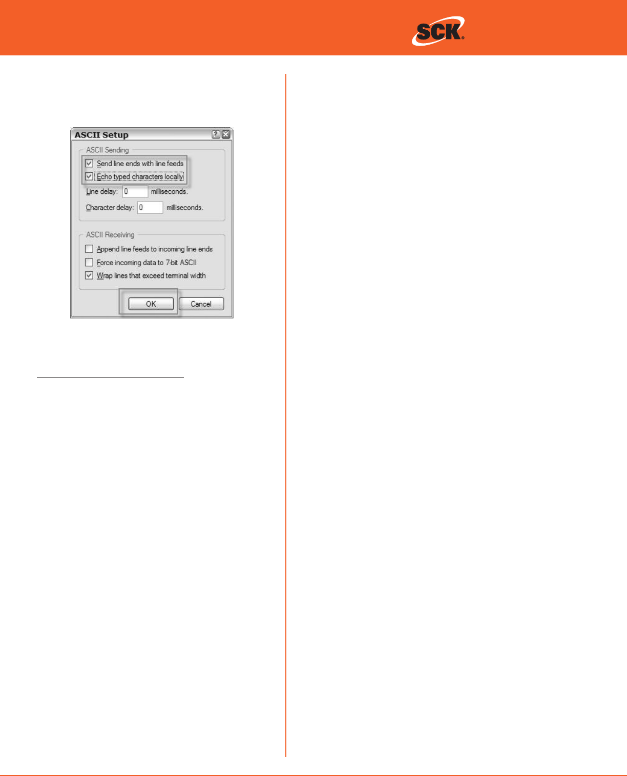
9. Check off, Send Lines ends with line feeds, Echo
typed characters locally boxes. Then click OK. On
the Properties screen click OK. Click on Call but-
ton Icon.
10. Below is a list of commands that can be used to
change the Parameters on the SmartDirect 2:
Configurable on the SmartDirect 2:
- Unique ID (supplied by manufacturer)
- Modem IP address (supplied by customer on site
survey)
- Gateway IP address (supplied by customer on
site survey)
- Net mask IP address
- DNS server1 IP address (supplied by customer on
site survey)
- DNS server2 IP address (supplied by customer on
site survey)
- TCP server IP address (supplied by SCK)
- TCP server port (supplied by SCK)
- TCP server ID (Not used at this time)
- TCP server password (Not used at this time)
-Network server name is used for GPRS version
(installed at factory)
-Network ID is used for GPRS version (installed at
factory)
- Network password is used for GPRS version
(installed at factory)
- ISP provider number is used for GPRS version
(installed at factory)
- Modem type (GPRS or Ethernet)
- Connection interval (Minimum time between
connections to the server.)
- Silence timeout (Maximum time between trans-
actions.)
- Retry timeout: (Minimum time delay between
command retries.)
- Mode (configure or initialize or shutdown)
i. Configure: Device must be put into this
mode to change parameters.
ii. Initialize: Initialize the modem with saved
parameters.
iii. Shutdown: prepare the device for powering
off.
- Battery power (on or off)
i. On: Device uses the battery when line power
is removed.
ii. Off: Device does not use the battery.
- Reload defaults (Factory default settings will
be restored)
These parameters may be configured over the serial
connection locally using the following commands:
set:[parameter]=[value]used to change a
parameter
get:[parameter] used to return a parameter
value
send:[string to send]used to send commands
directly to the socket modem
report ‡provides a dump of system settings and
information
[parameter] = configurable parameter name
[value] = a string representing the new value.
(example “172.168.1.1”)
To reload factory defaults the user shall use the “set:”
command format with the exception that the
“=[value]” will be omitted.
The report and get commands may be used at any-
time.
In order to change a parameter, the device shall first
be placed into configuration mode (set:mode=con-
figure) which will go into effect when the device is
not currently connected to the host (i.e. the device is
idle or in error modes). Once in configuration mode,
the “set” commands shall be used to change parame-
ters.
To return to normal operation and load all of the
changes, the mode shall be changed to initialization
(set:mode=initialize) by the user. The modem shall
be reloaded using the new parameters.
SmartDirect 2TM Direct, Inc.

11
© 2007-2009 SCK Direct, Inc. 229-51363 Rev C www.MySCK.com
GPRS VERSION—PRE-INSTALLED AT
FACTORY
If using a GPRS version of SmartDirect 2:
The following settings should already be configured:
Check your report. If settings are already correct, skip
this step. These settings are configured at the factory.
If the settings are incorrect, call the SCK helpdesk to
get the correct settings. Every unit uses different set-
tings.
1. Type in set:modem type=GPRS then Enter.
2. Type in set:tcp server ip address= call SCK
helpdesk for info, if necessary.
3. Type in set:tcp server port= call SCK helpdesk for
info, if necessary.
4. Type in set:network server name= call SCK
helpdesk for info, if necessary.
5. Type in set:network id= call SCK helpdesk for
info, if necessary.
6. Type in set:network password= call SCK helpdesk
for info, if necessary.
Once the SmartDirect 2 is configured, the unit will
then need to be initialized.
1. Type in set:mode=initialize then enter.
2. Check the setting by running another report.
3. Type in REPORT then enter. All your settings
should now be configured.
4. Exit out of the set up.
TIER 2 PROGRAMMING:
1. Type in REPORT then press Enter. The screen will
show all the current settings in the SmartDirect 2.
NOTE: AFTER YOU PRESS ENTER YOU SHOULD GET
A RESPONSE OF OK.
Using your site survey information set the following
settings.
TO SET UP THE CONFIGURATION
(FOR BOTH VERSIONS):
1. Type in set:mode=configure
ETHERNET VERSION
1. Type in set:modem ip address=XXX.XX.X.X (your
address here) then enter.
2. Type in set:gateway ip address=XXX.XX.X.X (your
address here) then enter.
3. Type in set:dns server1 ip
address=XXX.XXX.XXX.X (your address here) then
enter.
4. Type in set:dns server2 ip
address=XXX.XXX.XXX.X (your address here) then
enter.
The following settings should already be configured:
Check your report. If settings are already correct, skip
this step. These settings are configured at the factory.
If the settings are incorrect, call the SCK helpdesk to
obtain the correct settings. Every unit uses different
settings.
1. Type in set:modem type=Ethernet then Enter.
2. Type in set:tcp server ip address= call SCK
helpdesk for info, if necessary.
3. Type in set:tcp server port= call SCK helpdesk for
info, if necessary.
installation guide

Direct, Inc.
Thank You for Choosing
SCK Direct, Inc!
SCK Direct, Inc.
905 Honeyspot Road
Stratford, CT 06615 USA
+1 203.377.4174 voice
+1 203.377.8187 fax
1.866.840.4271 toll-free sales & helpdesk
www.MySCK.com; info@mysck.com
229-51363 Rev. C
© 2007-2009 SCK Direct, Inc.
Printed in the USA
06FEB2009
Troubleshooting
Should you experience problems installing your SCK Xwire prod-
ucts, or any aspect of your SCK Direct, Inc. services, please contact
the SCK HelpDesk toll-free at 1.866.840.4271.
Optional SCK System Components
SCK has a variety of optional accessories to help you complete
your kitchen automation:
SCK Kitchen Advisor Information Server
SCK Remote Input Device
SCK KSM Kitchen Status Monitor
SCK-Enabled Appliance Controllers
SCK Wireless (XwireTM) Appliance Interface
SCK Wireless (XwireTM) Temperature/Door SmartSensorTM
SCK Wireless (XwireTM) SmartGateway
SCK Wired Backbone
For additional information on any of these accessories, or to
request Technical Specification Sheets, please contact your SCK
Representative or contact SCK Customer Support toll-free at
1-866-840-4271 (Monday-Friday, 8:00 a.m. to 5:00 p.m. EST).
This document contains confidential information. The dissemina-
tion, publication, copying, or duplication of this document or the
software described herein without prior written authorization is
strictly prohibited.
Specifications subject to change without notice.
(FAST.)® is a registered trademark of Food Automation - Service
Techniques, Inc.
Smart Commercial Kitchen and SCK are registered trademarks of
Technology Licensing Corporation.
SCK Direct, Inc. products are covered under U.S. and foreign
patents, plus patents pending.
WARRANTY
SCK Direct, Inc. warrants all new Xwire hardware for 1 year from the
date of purchase. SCK Direct, Inc. warrants all other items for a peri-
od of 90 days unless otherwise stated at the time of purchase.