Fortinet FORTIWIFI-60 Wireless Firewall User Manual users manual 1
Fortinet, Inc Wireless Firewall users manual 1
UserManual.wiki
>
Fortinet
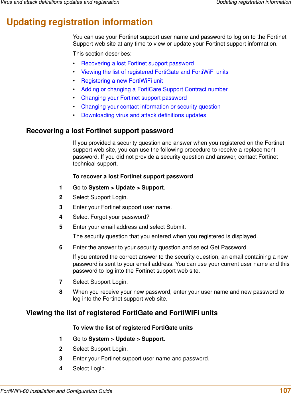
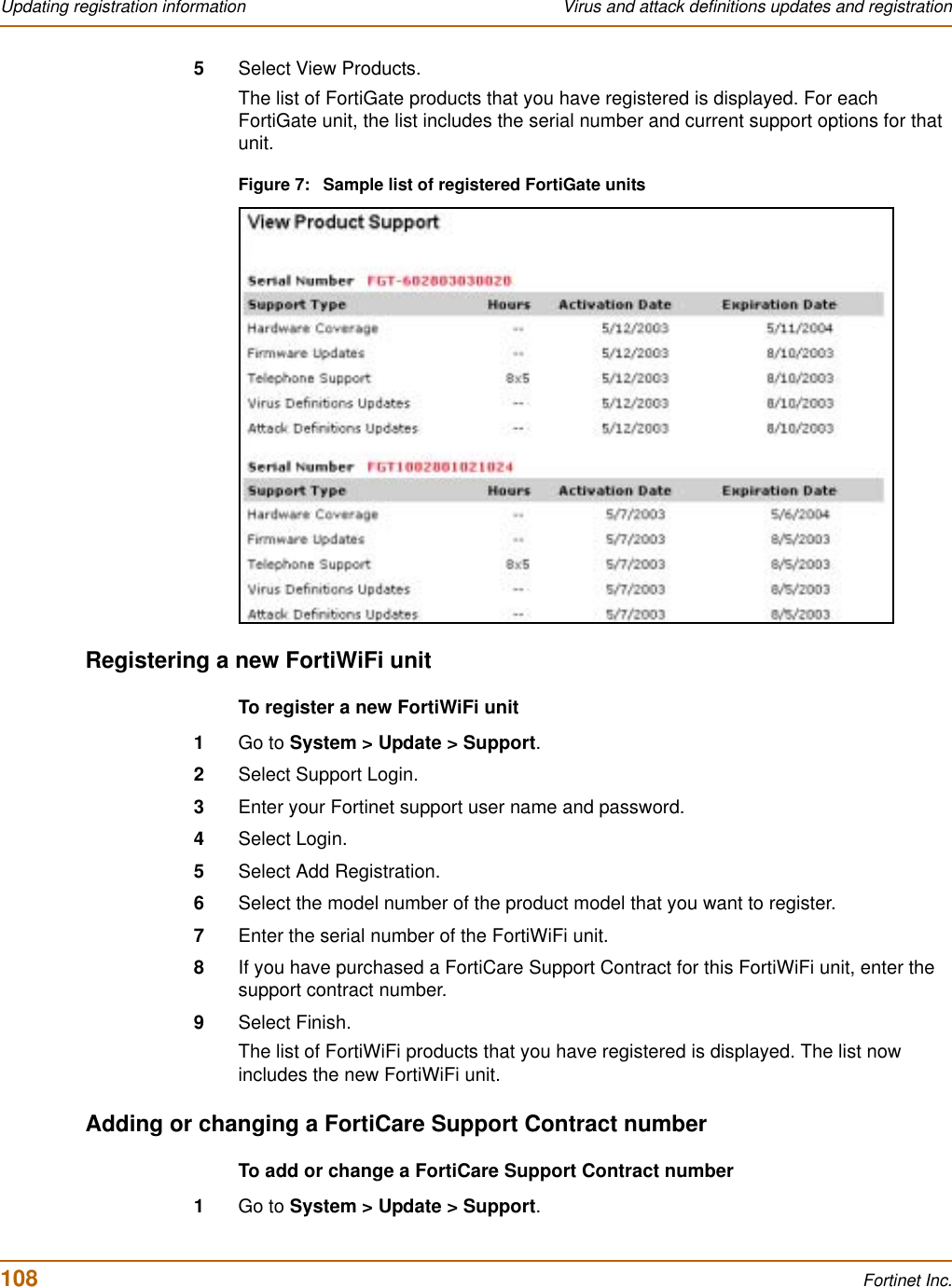
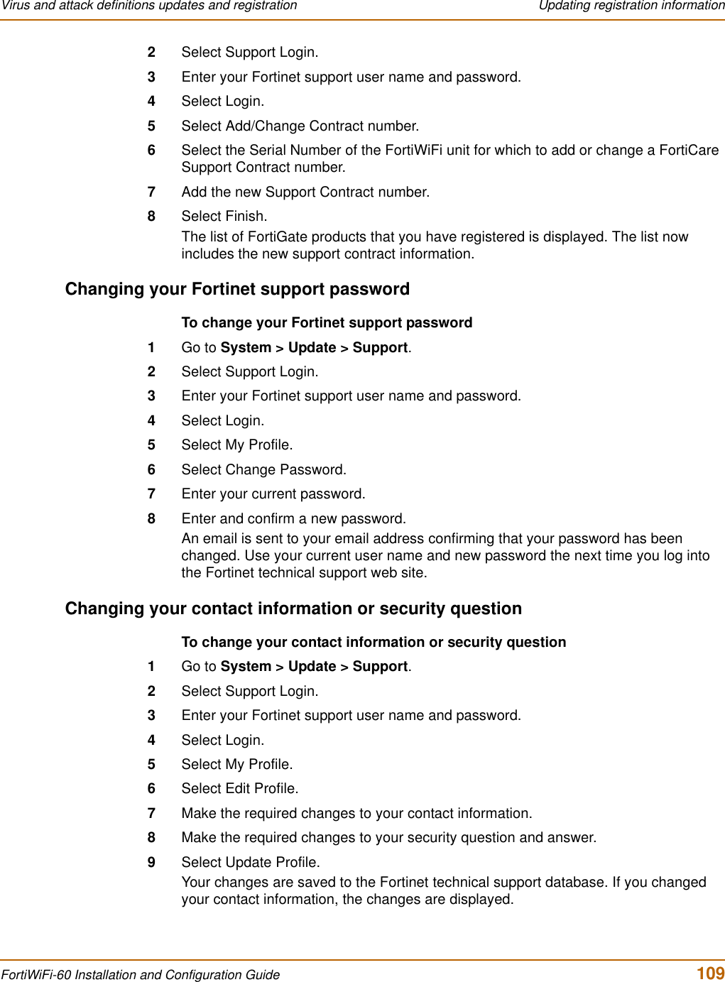
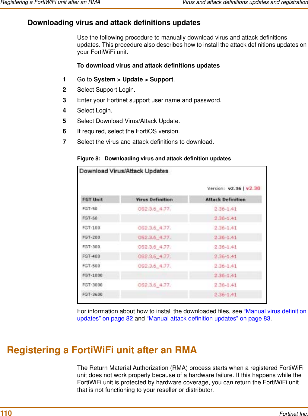
>
FORTIWIFI-60 User Manual
>
users manual 1
Contents
1.
users manual 1
2.
users manual 2
users manual 1
Navigation menu
Upload a User Manual
Namespaces
Wiki Guide
HTML
PDF
Info
Views
User Manual
Discussion / Help
Navigation
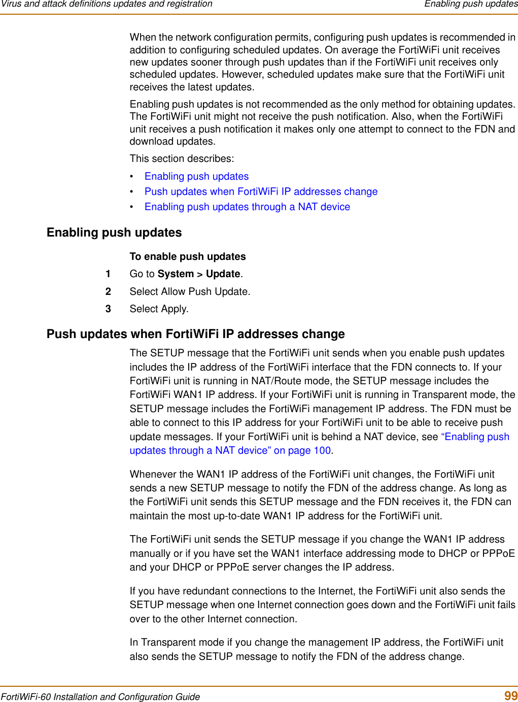
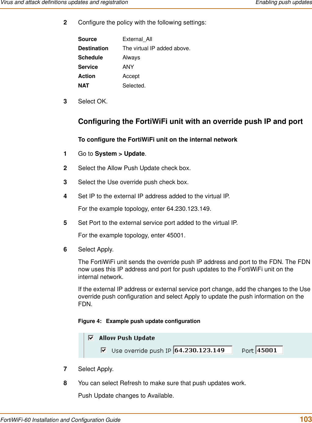
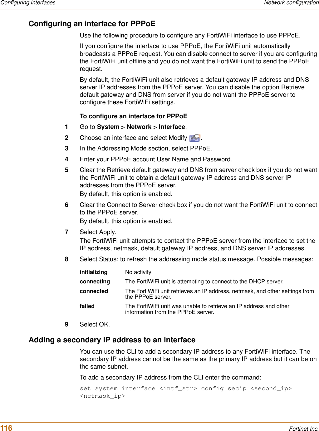
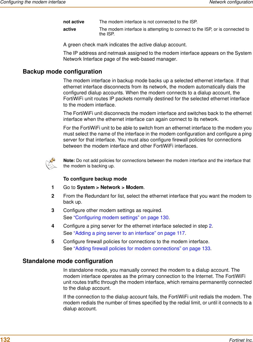
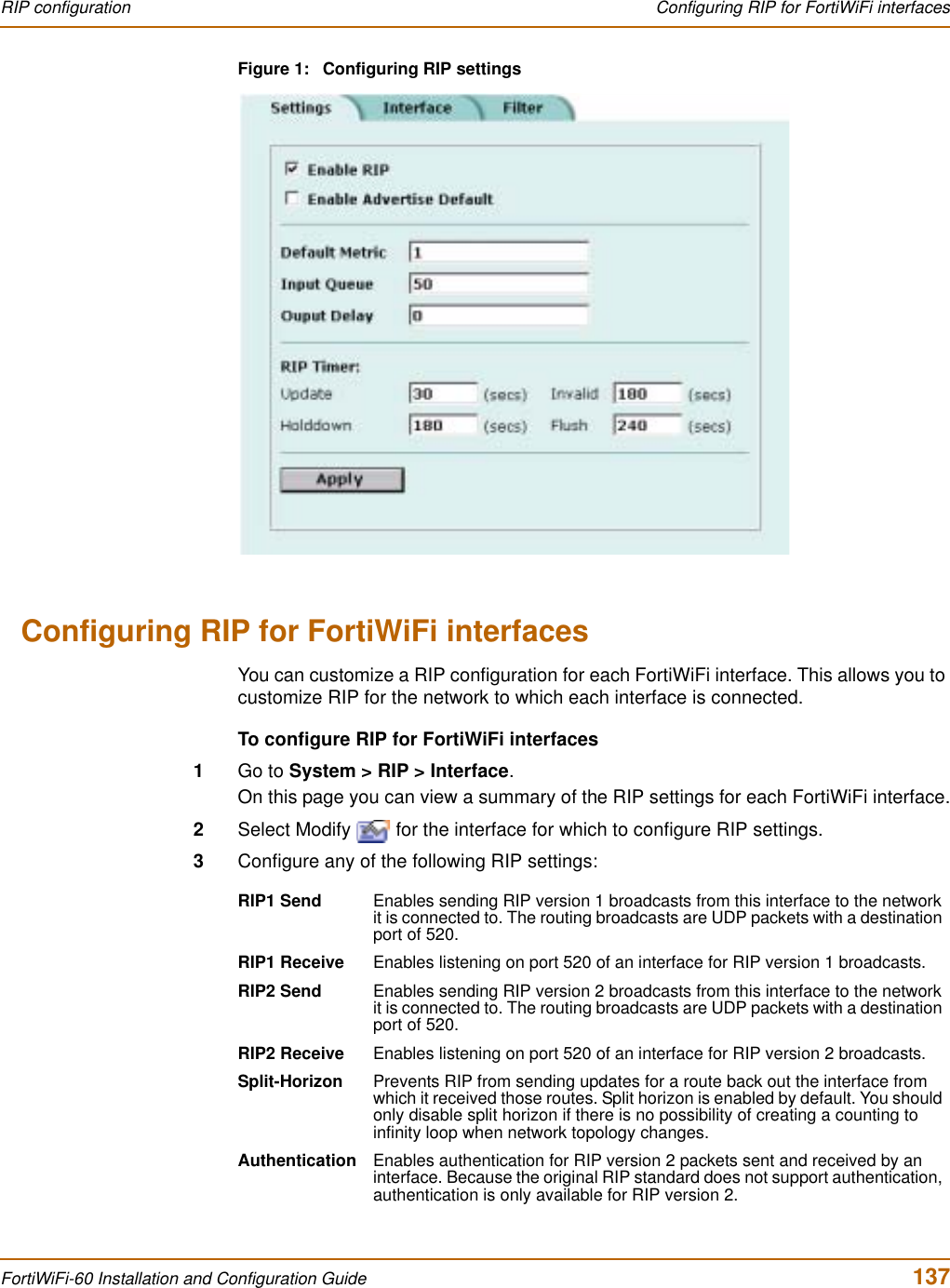
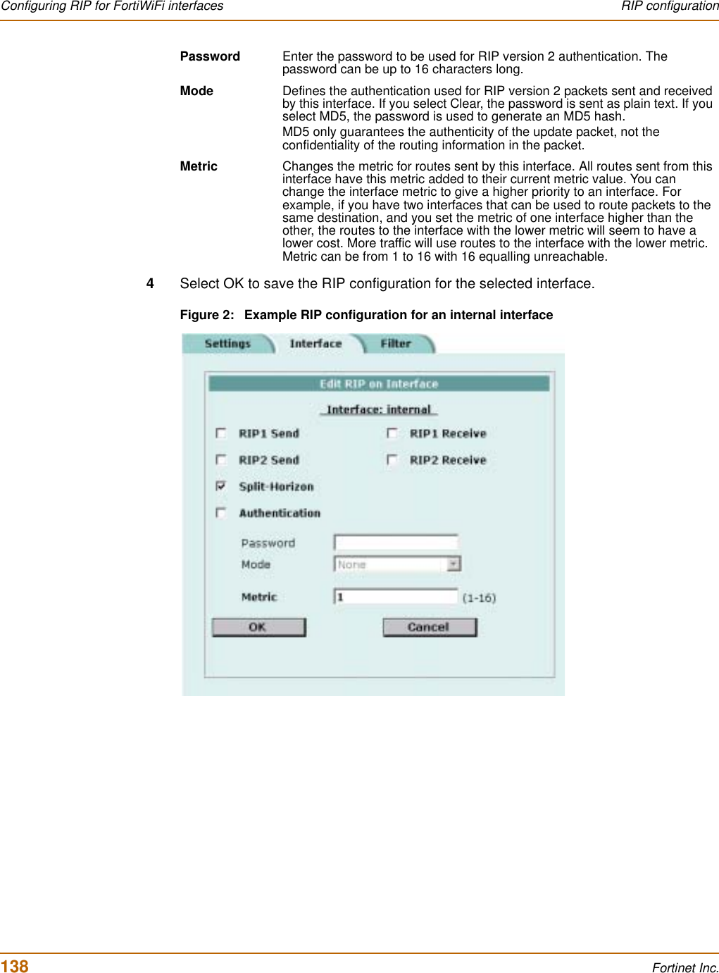
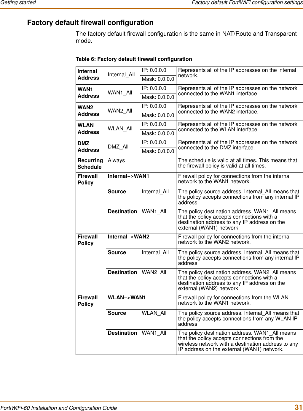
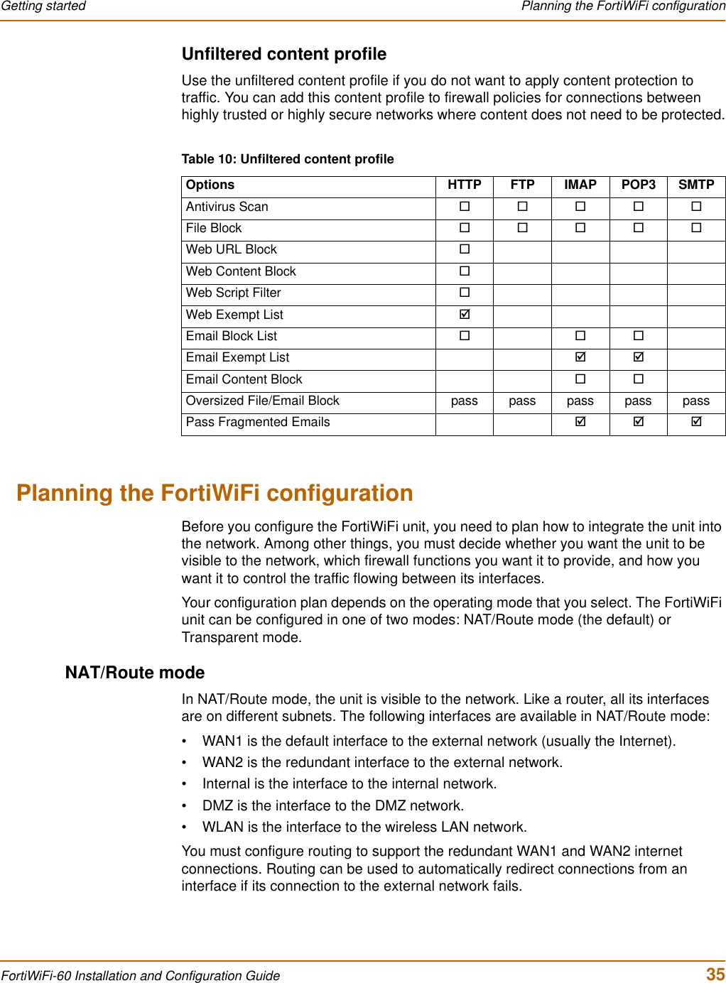
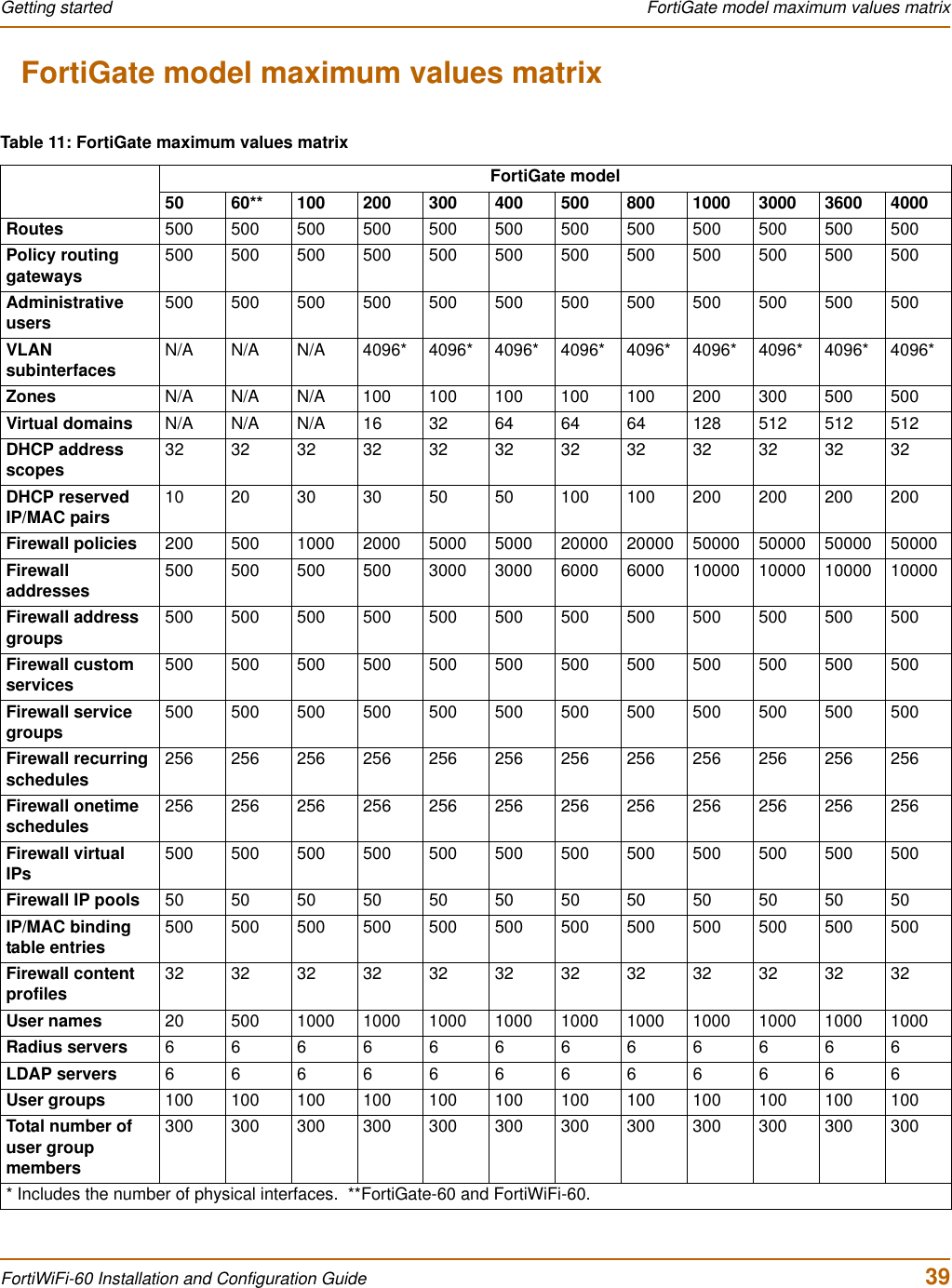
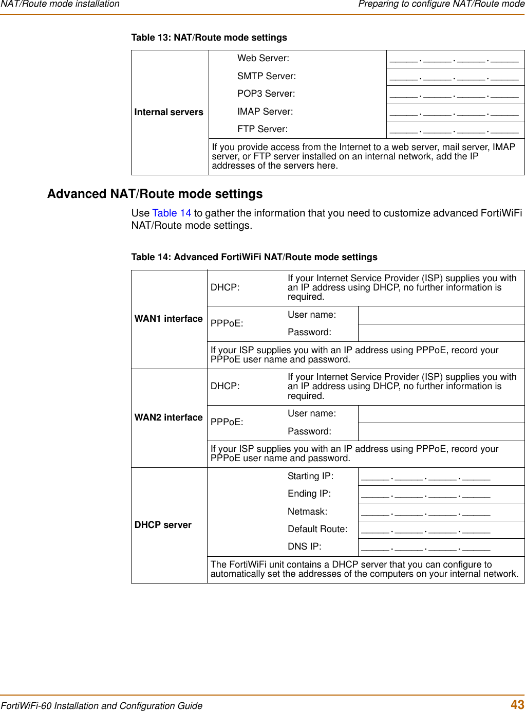
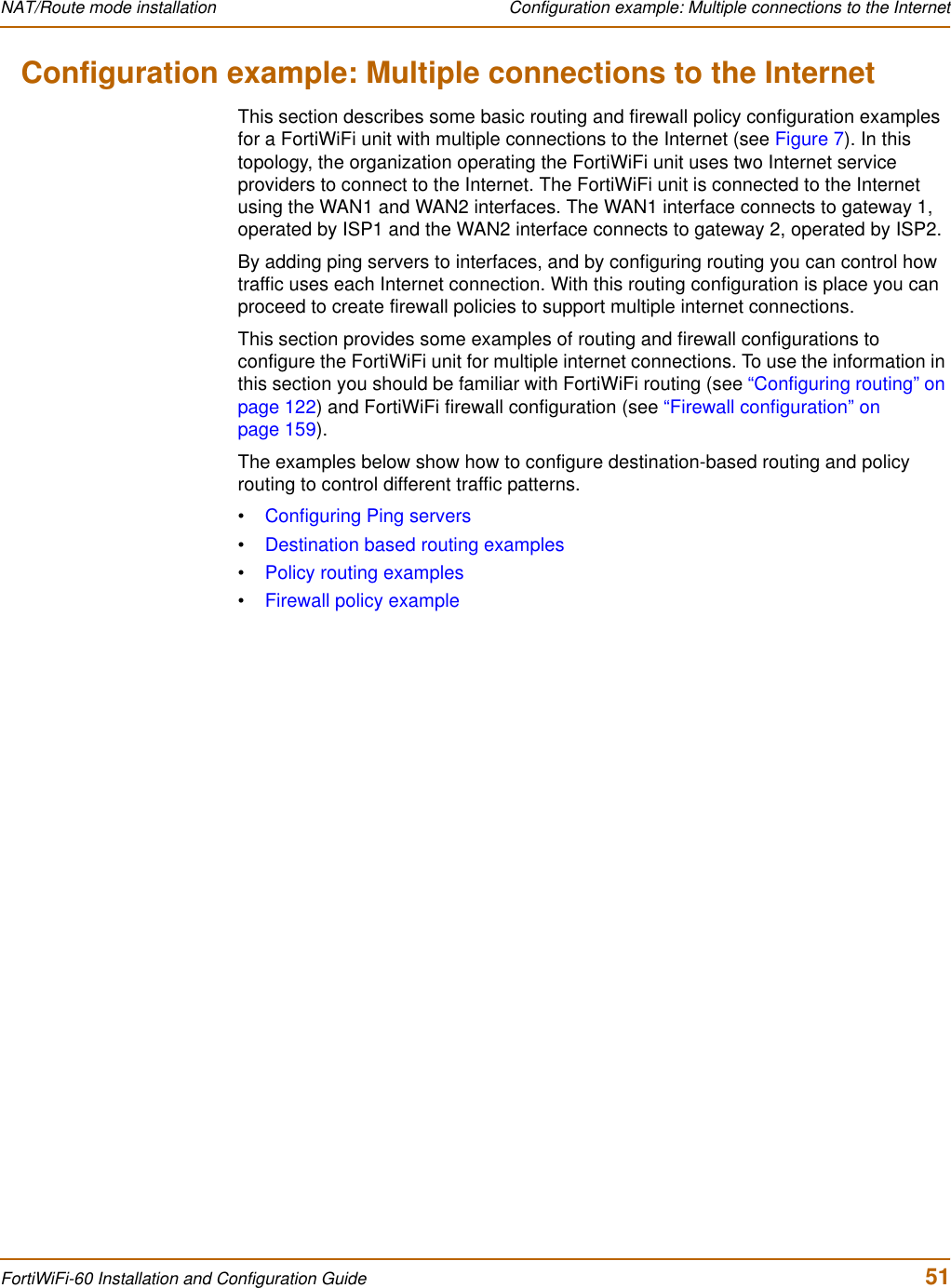
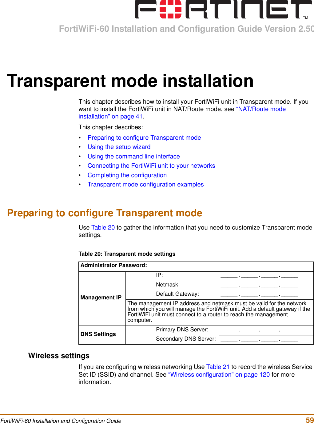
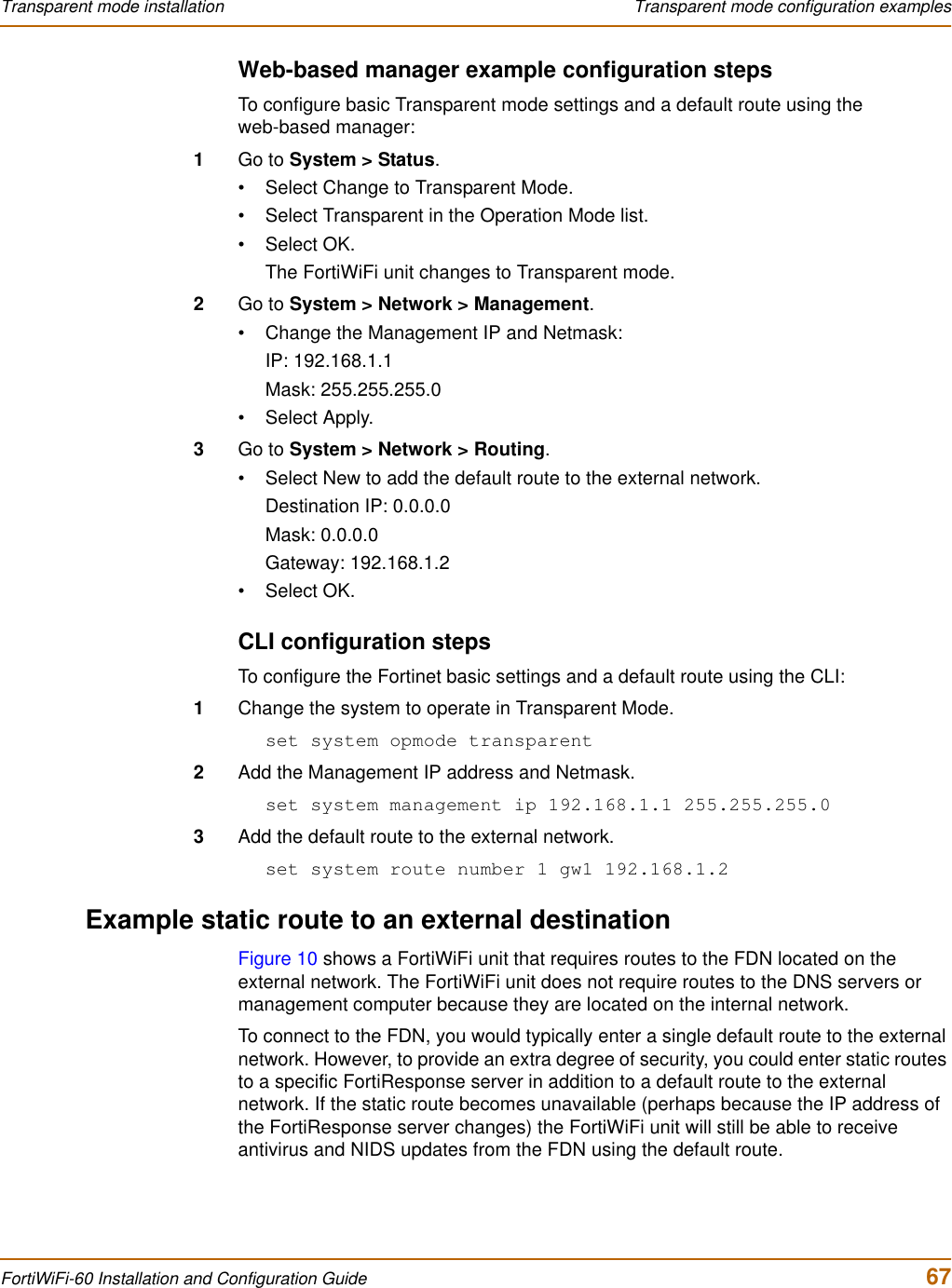
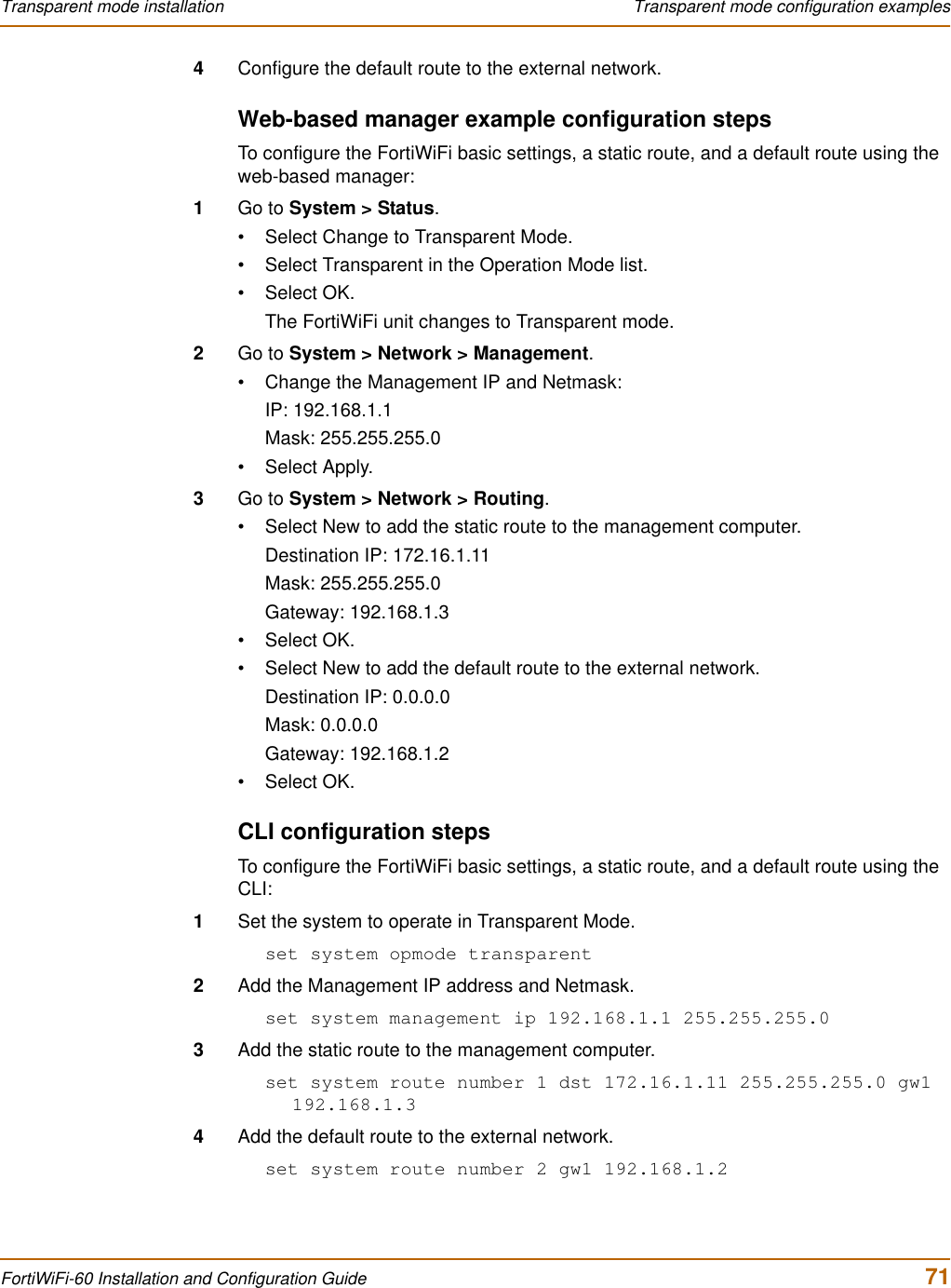
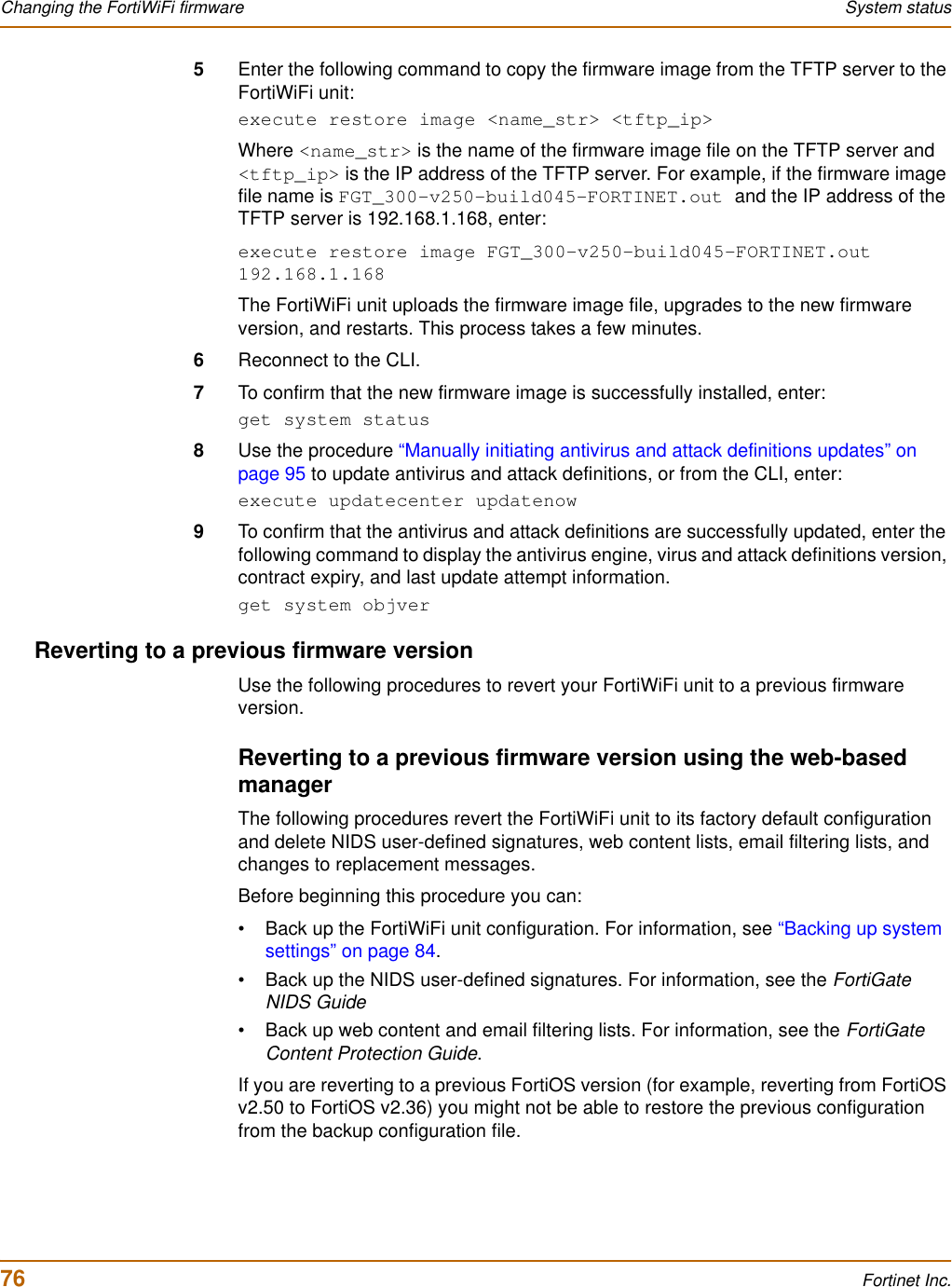
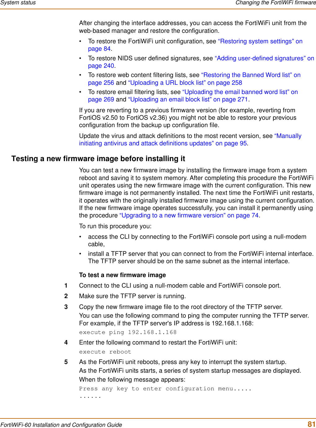
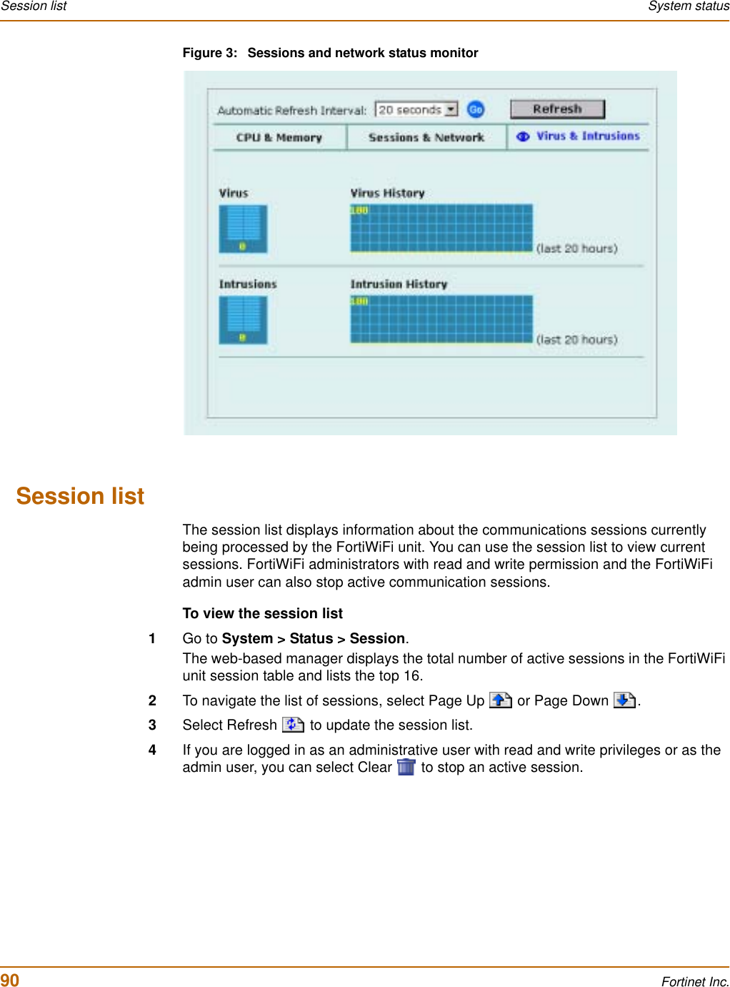
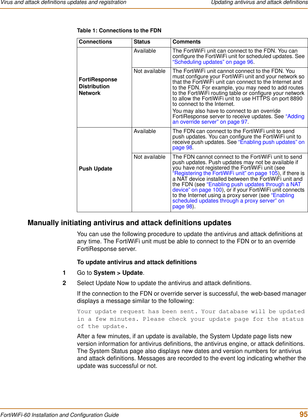
![Introduction Document conventionsFortiWiFi-60 Installation and Configuration Guide 19Logging and reportingThe FortiWiFi unit supports logging for various categories of traffic and configuration changes. You can configure logging to:• report traffic that connects to the firewall,• report network services used,• report traffic that was permitted by firewall policies,• report traffic that was denied by firewall policies,• report events such as configuration changes and other management events, IPSec tunnel negotiation, virus detection, attacks, and web page blocking,• report attacks detected by the NIDS,• send alert email to system administrators to report virus incidents, intrusions, and firewall or VPN events or violations.Logs can be sent to a remote syslog server or a WebTrends NetIQ Security Reporting Center and Firewall Suite server using the WebTrends enhanced log format. Some models can also save logs to an optional internal hard drive. If a hard drive is not installed, you can configure most FortiWiFi units to log the most recent events and attacks detected by the NIDS to the system memory.Document conventionsThis guide uses the following conventions to describe CLI command syntax.• angle brackets < > to indicate variable keywordsFor example:execute restore config <filename_str>You enter restore config myfile.bak<xxx_str> indicates an ASCII string variable keyword.<xxx_integer> indicates an integer variable keyword.<xxx_ip> indicates an IP address variable keyword.• vertical bar and curly brackets {|} to separate alternative, mutually exclusive required keywordsFor example:set system opmode {nat | transparent}You can enter set system opmode nat or set system opmode transparent• square brackets [ ] to indicate that a keyword is optionalFor example:get firewall ipmacbinding [dhcpipmac]You can enter get firewall ipmacbinding orget firewall ipmacbinding dhcpipmac](https://usermanual.wiki/Fortinet/FORTIWIFI-60.users-manual-1/User-Guide-418740-Page-19.png)

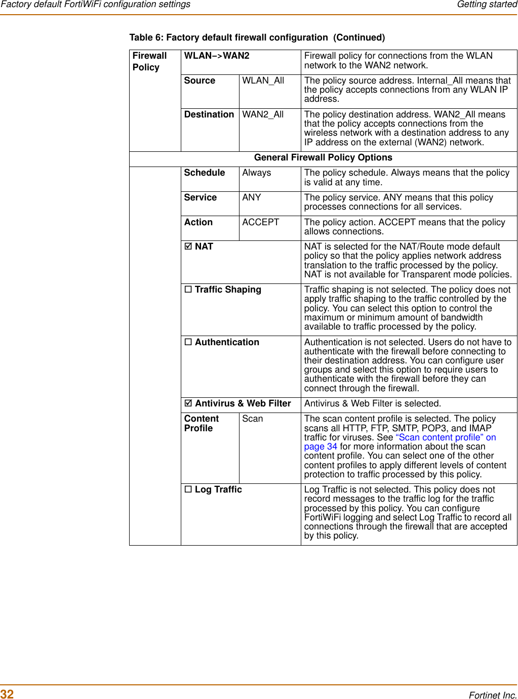
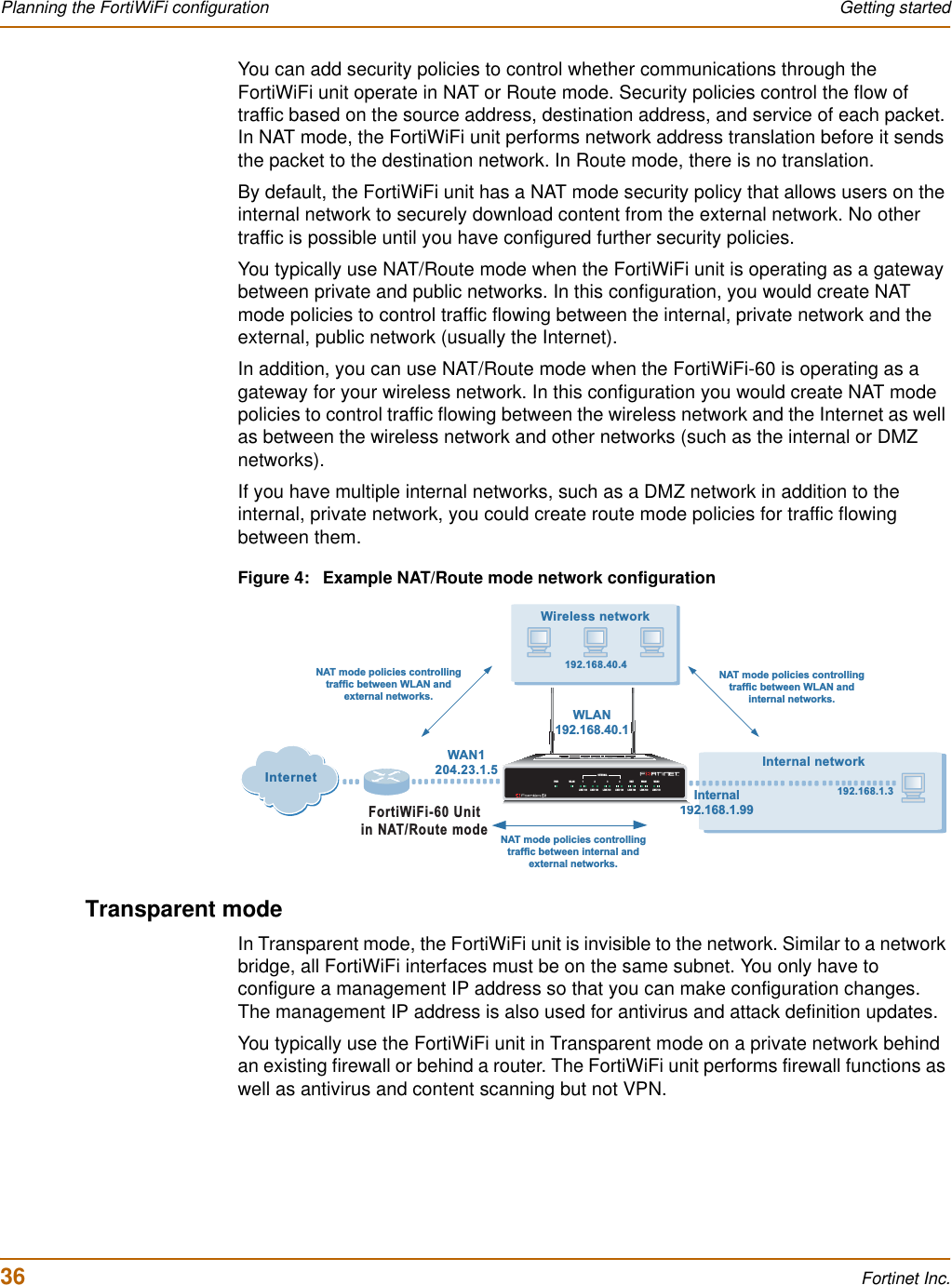
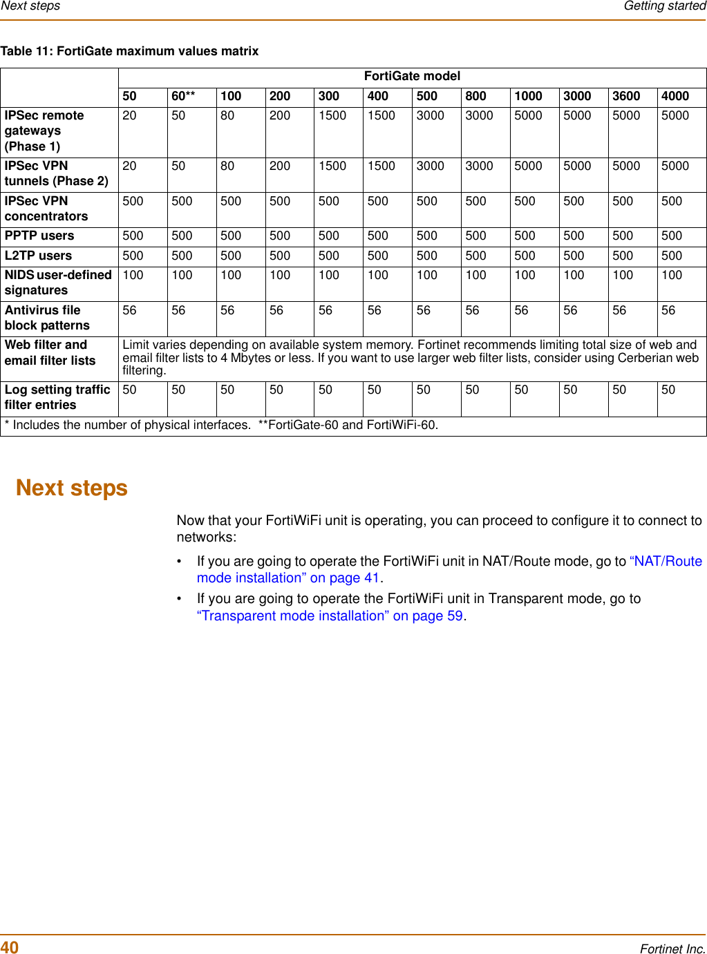
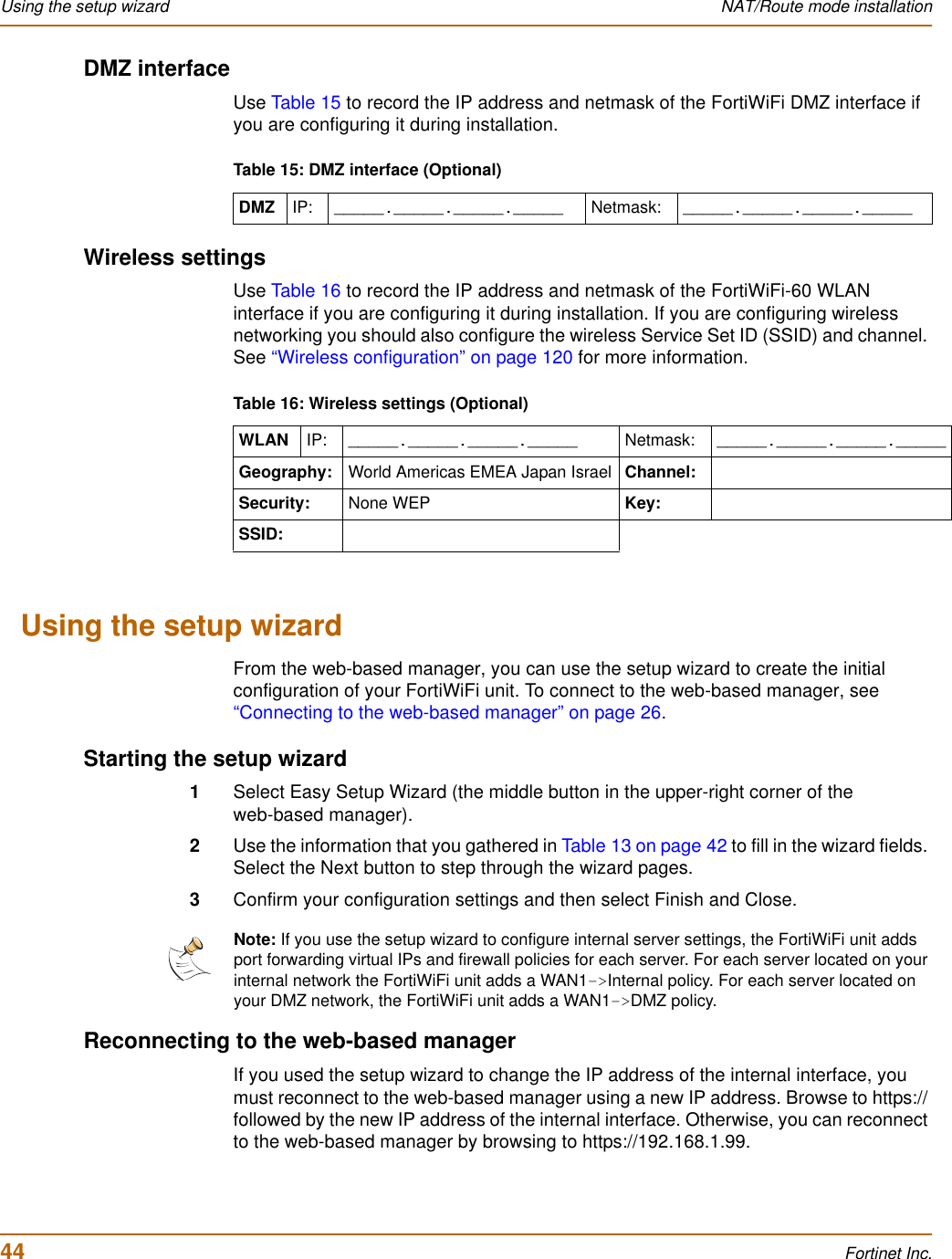
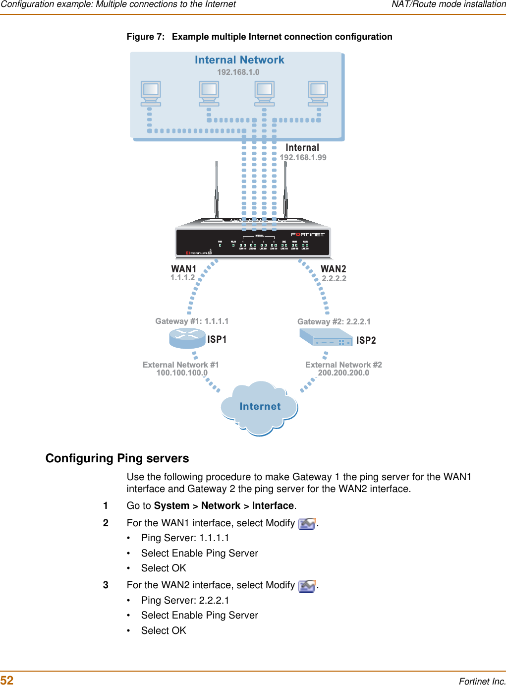
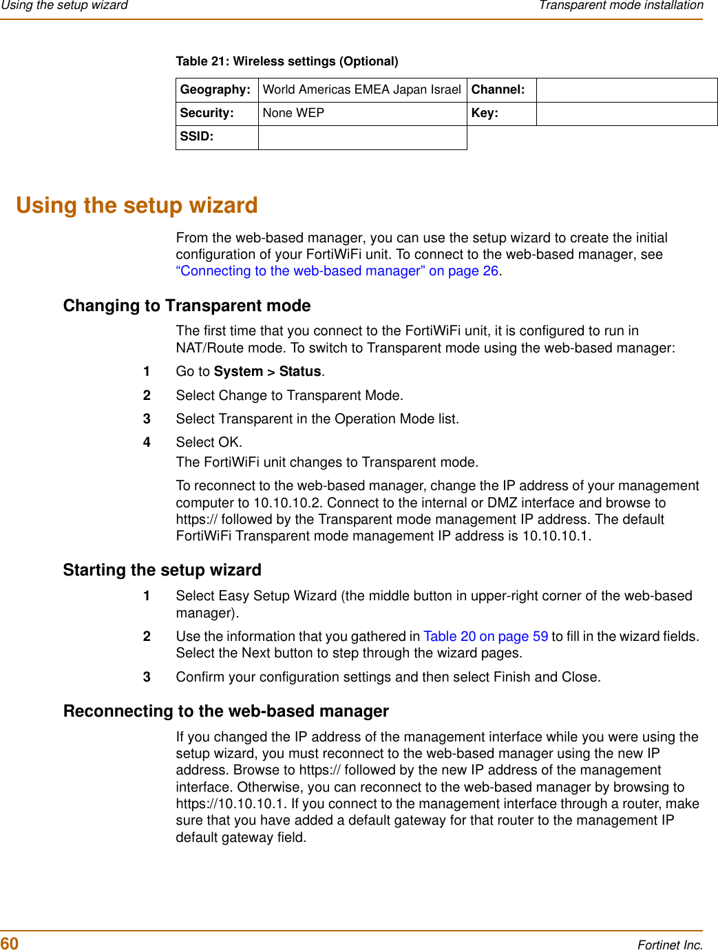
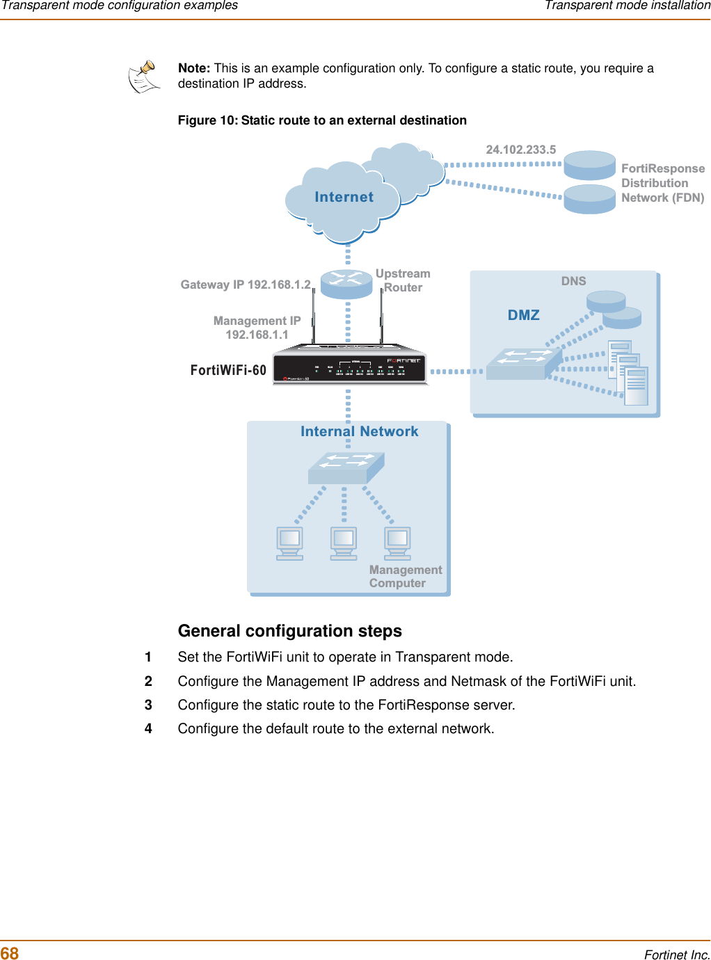

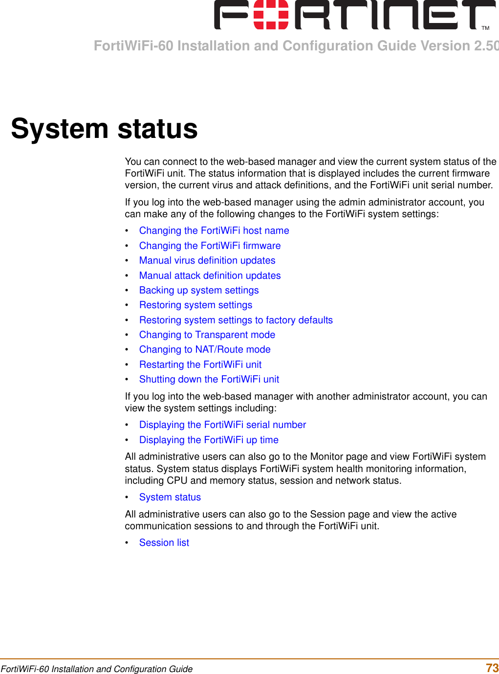
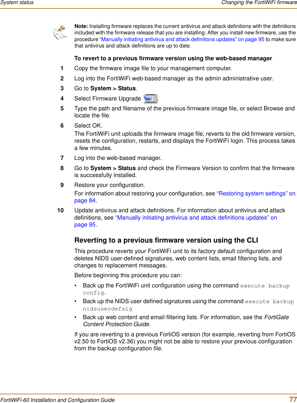
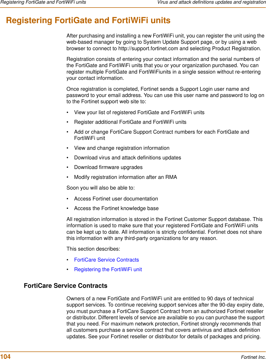
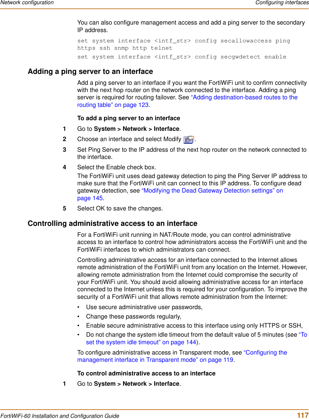
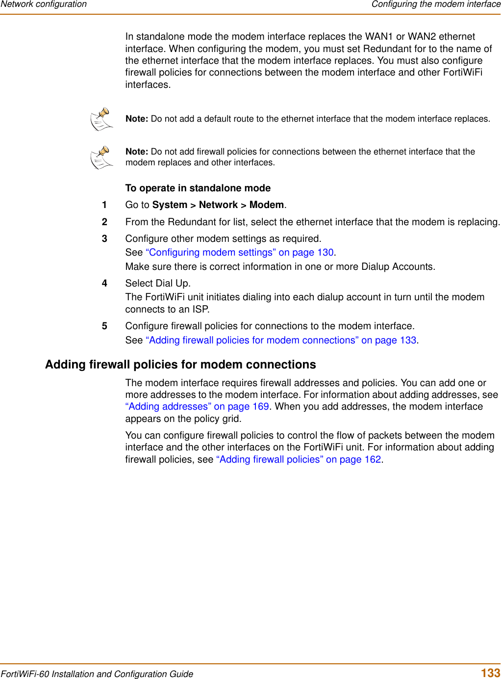
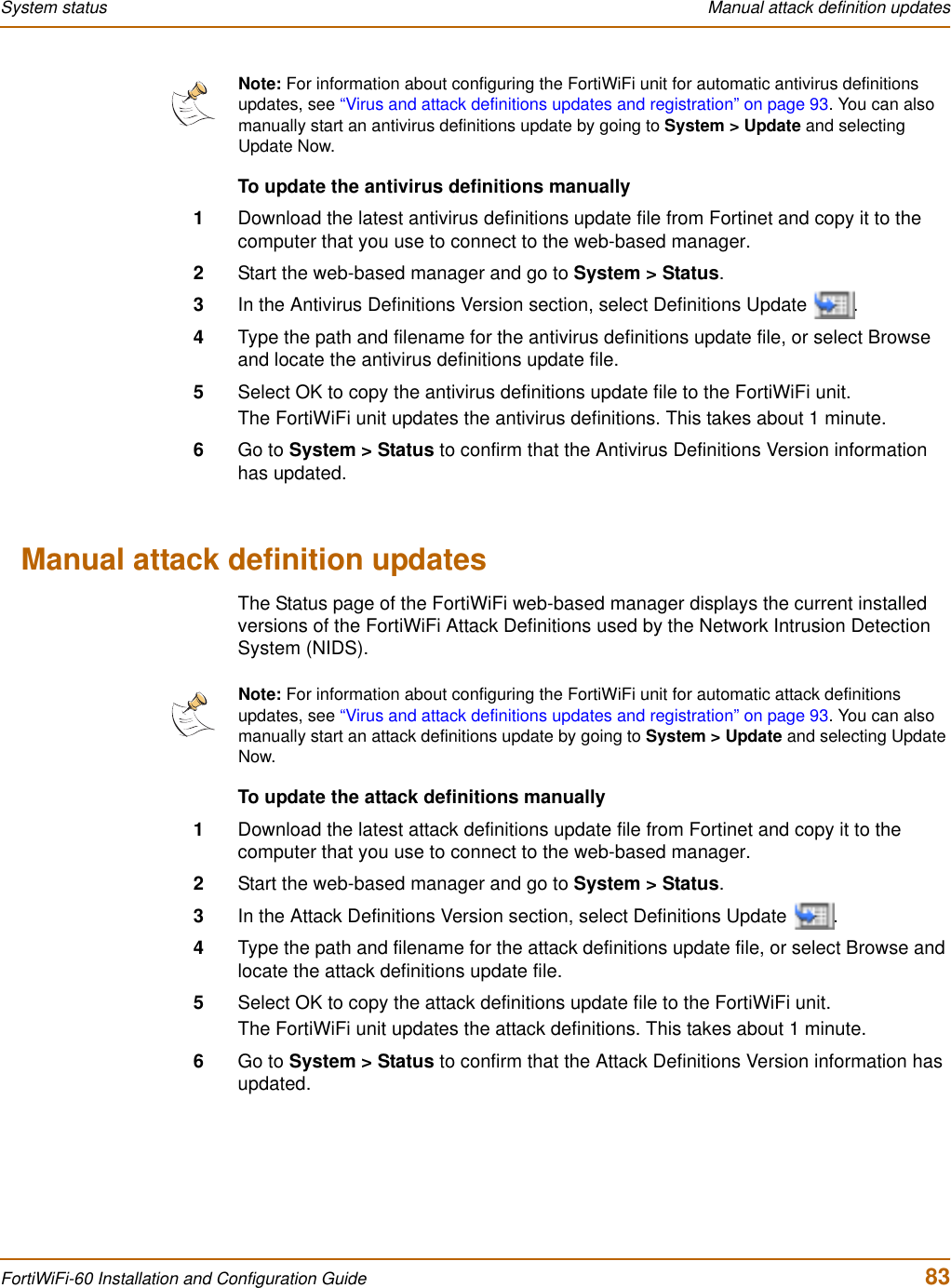
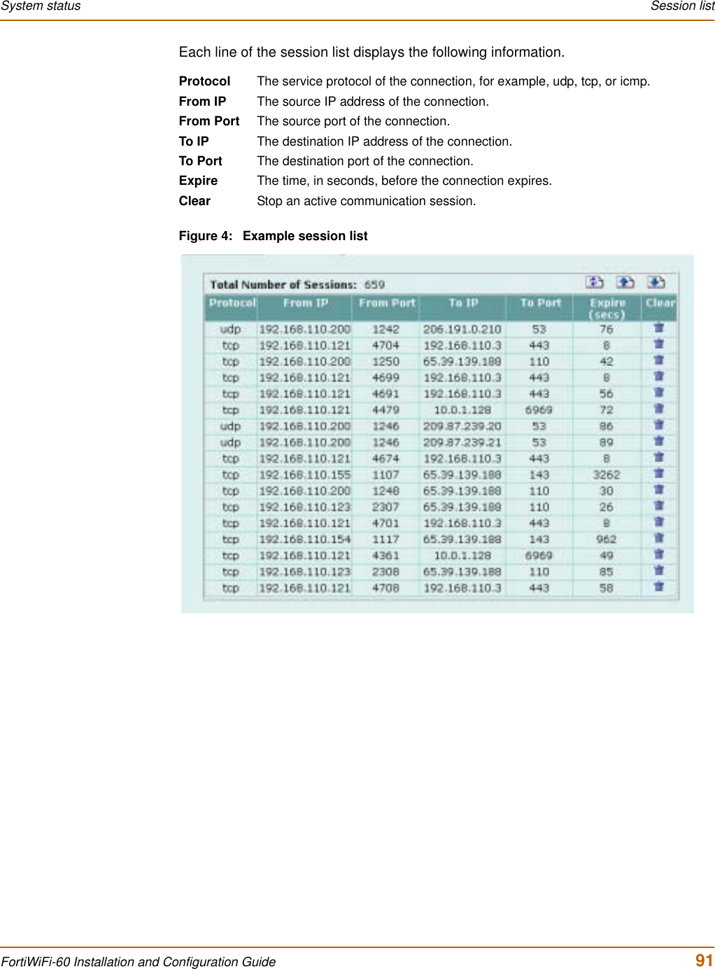
![80 Fortinet Inc.Changing the FortiWiFi firmware System status6Enter the following command to restart the FortiWiFi unit:execute rebootAs the FortiWiFi unit starts, a series of system startup messages is displayed.When the following message appears:Press any key to enter configuration menu...........7Immediately press any key to interrupt the system startup.If you successfully interrupt the startup process, the following message appears:[G]: Get firmware image from TFTP server.[F]: Format boot device.[B]: Boot with backup firmware and set as default.[Q]: Quit menu and continue to boot with default firmware.[H]: Display this list of options.Enter G,F,B,Q,or H:8Type G to get the new firmware image from the TFTP server.9Type the address of the TFTP server and press Enter.The following message appears:Enter Local Address [192.168.1.188]:10 Type the address of the internal interface of the FortiWiFi unit and press Enter.The following message appears:Enter File Name [image.out]:11 Enter the firmware image filename and press Enter.The TFTP server uploads the firmware image file to the FortiWiFi unit and messages similar to the following are displayed:Save as Default firmware/Run image without saving:[D/R]Save as Default firmware/Backup firmware/Run image without saving:[D/B/R]12 Type D.The FortiWiFi unit installs the new firmware image and restarts. The installation might take a few minutes to complete.Restoring the previous configurationChange the internal interface addresses if required. You can do this from the CLI using the command:set system interfaceNote: You have only 3 seconds to press any key. If you do not press a key soon enough, the FortiWiFi unit reboots and you must log in and repeat the execute reboot command.Note: The local IP address is used only to download the firmware image. After the firmware is installed, the address of this interface is changed back to the default IP address for this interface.](https://usermanual.wiki/Fortinet/FORTIWIFI-60.users-manual-1/User-Guide-418740-Page-80.png)
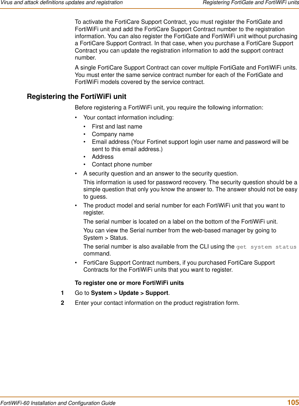
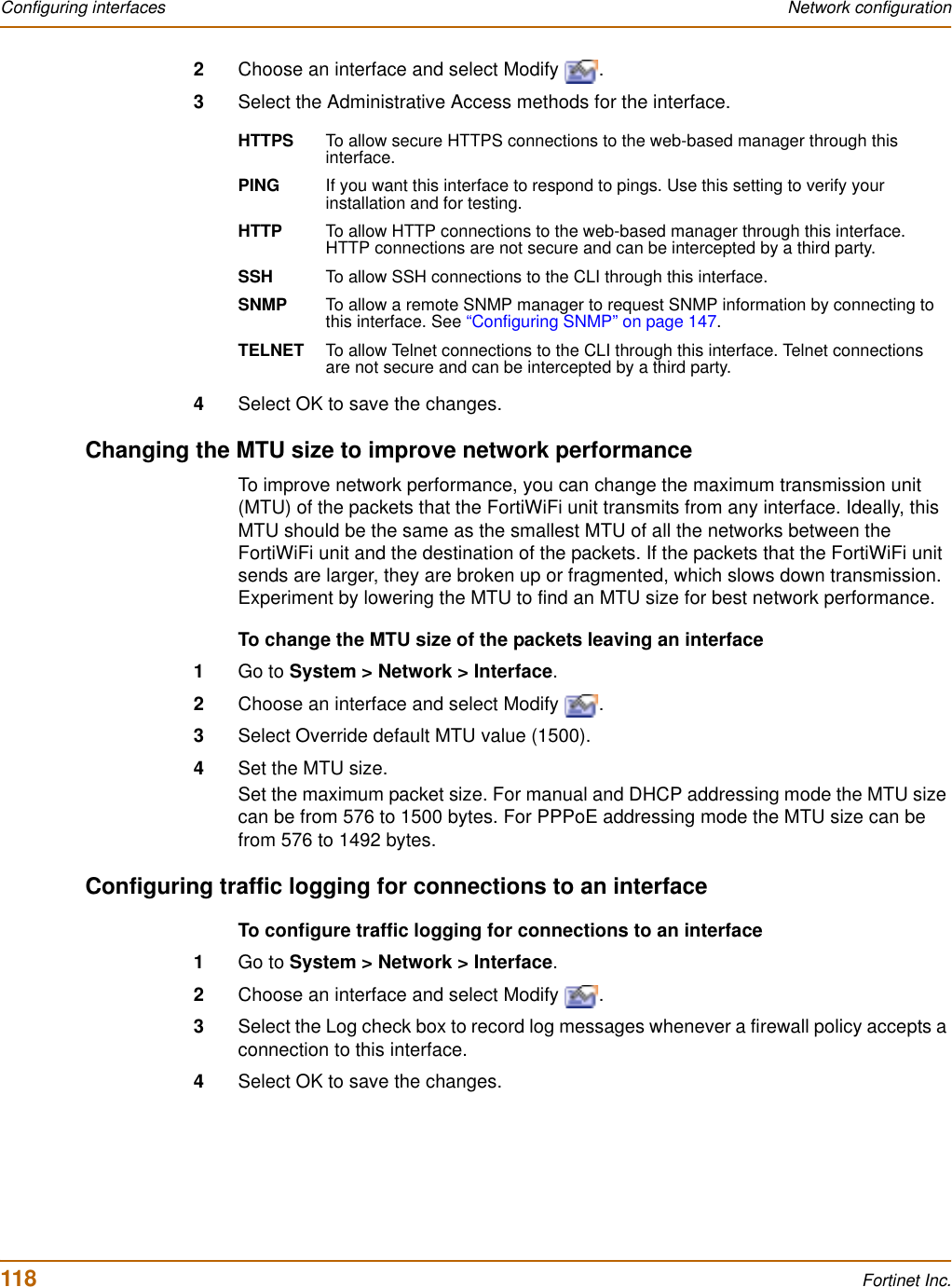
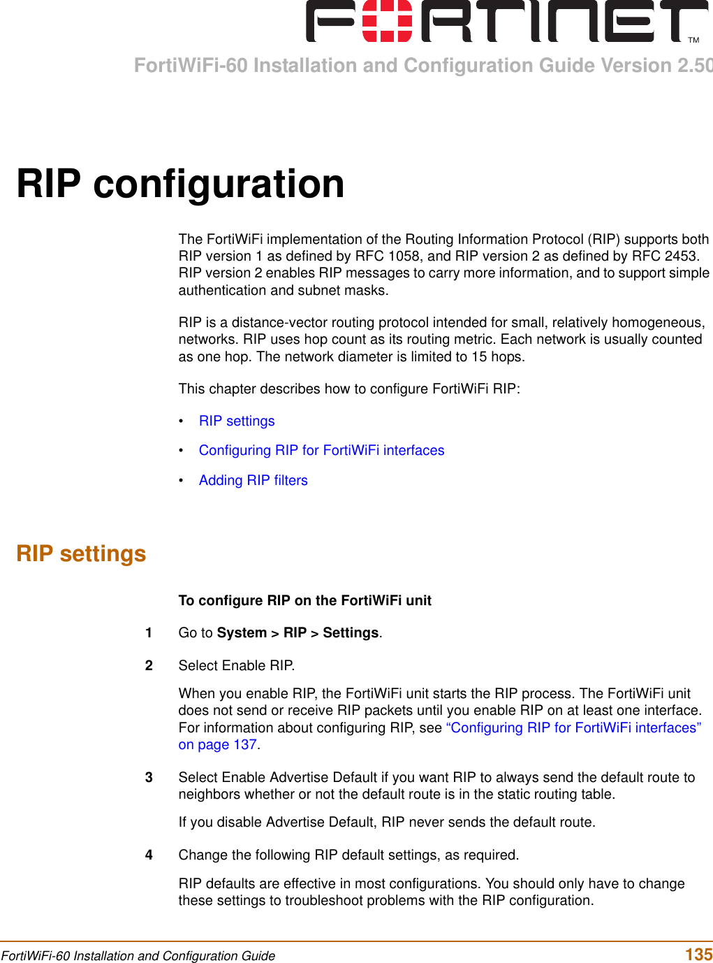
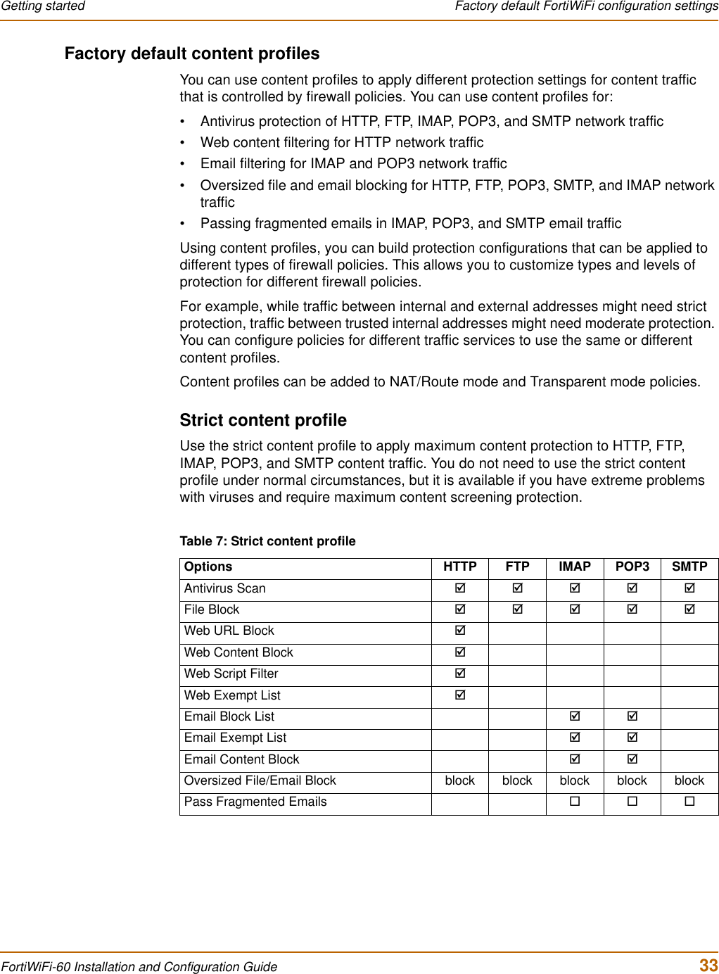
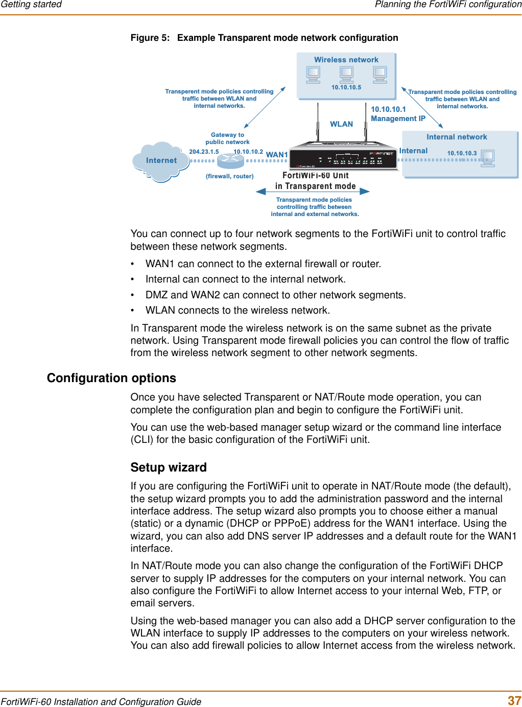
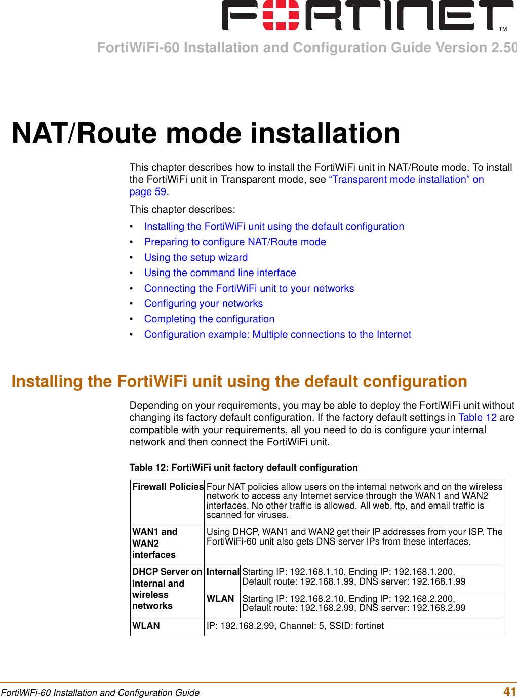
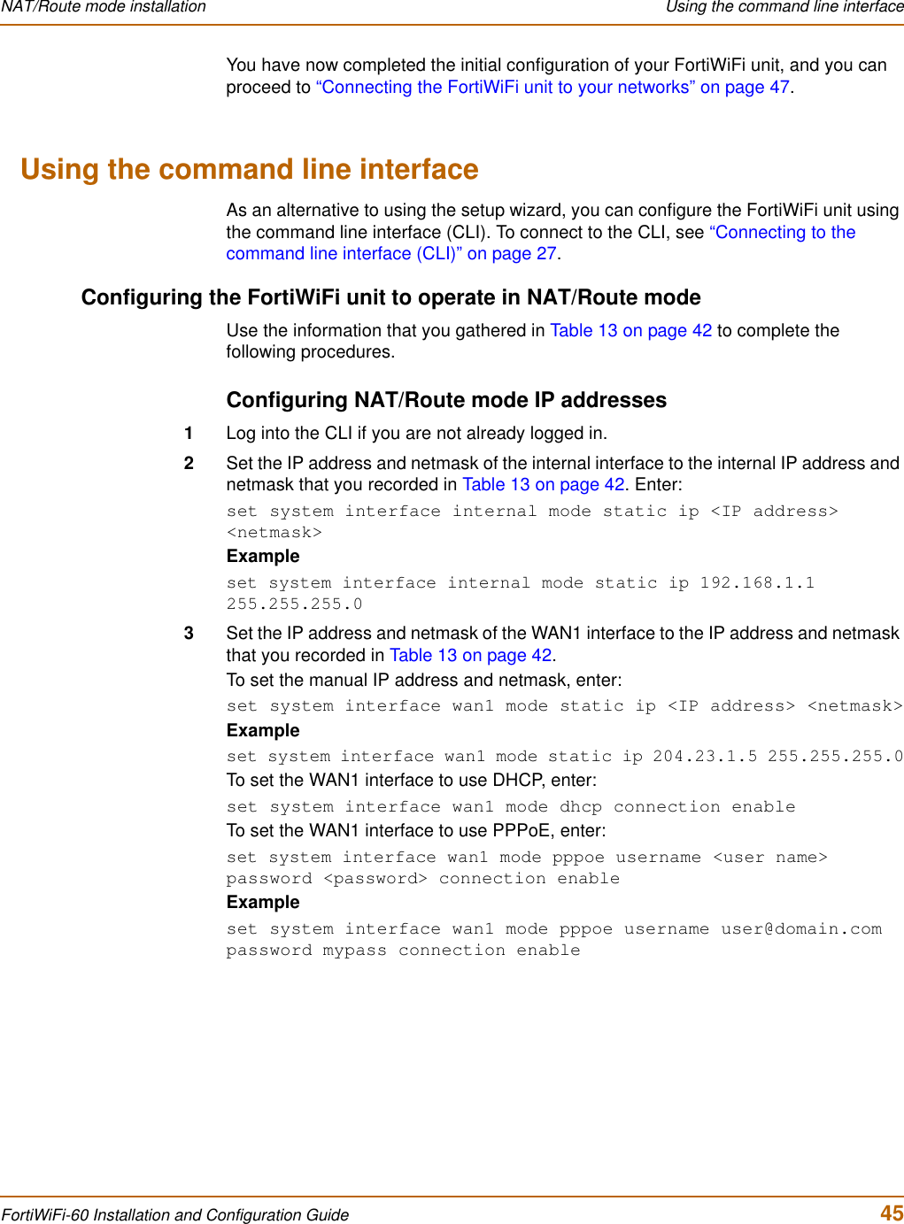
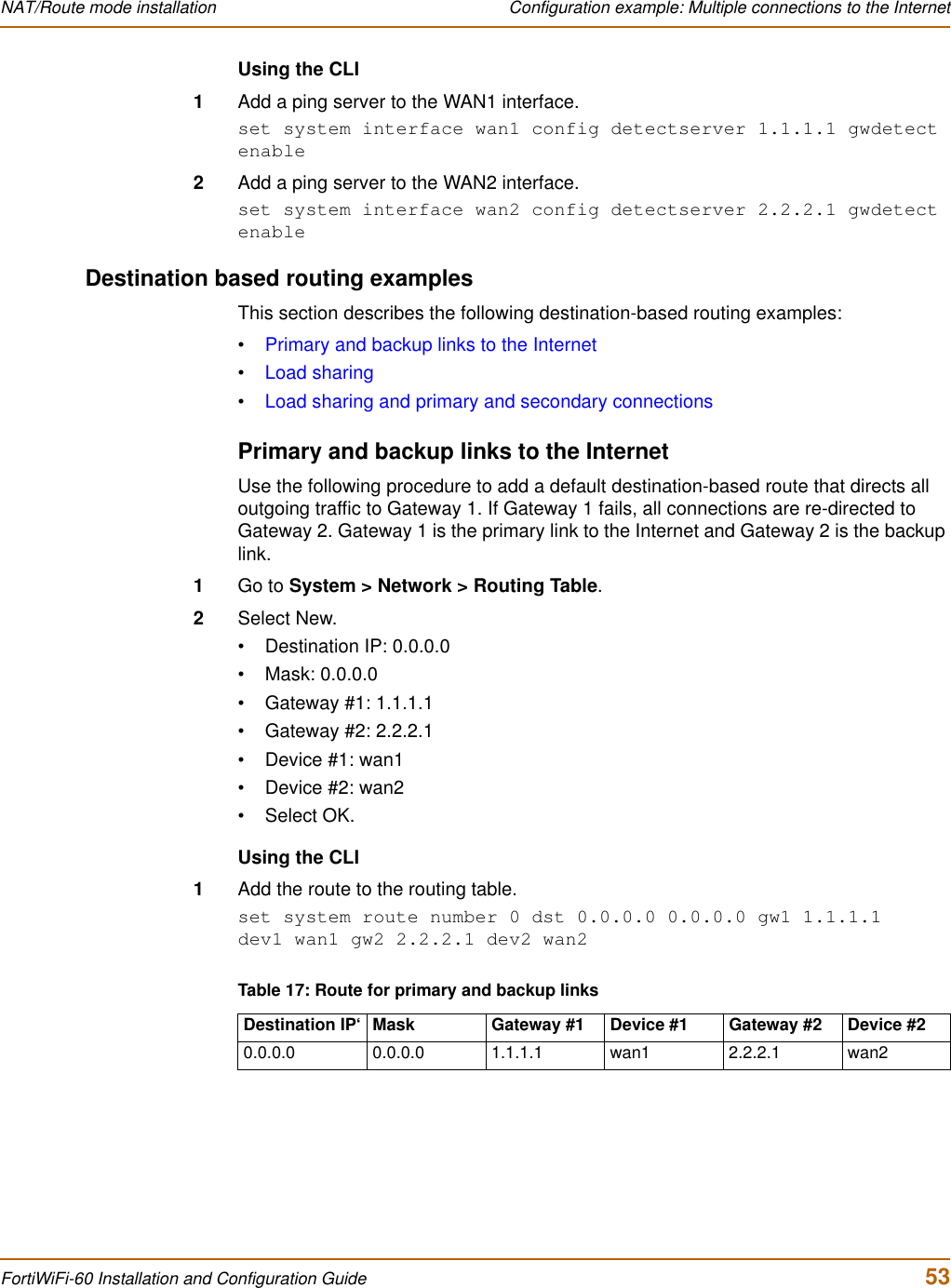
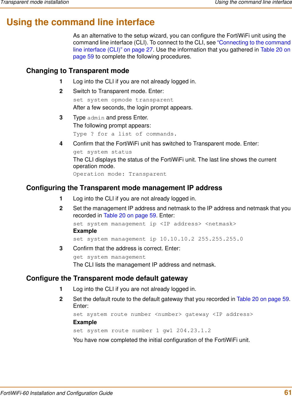
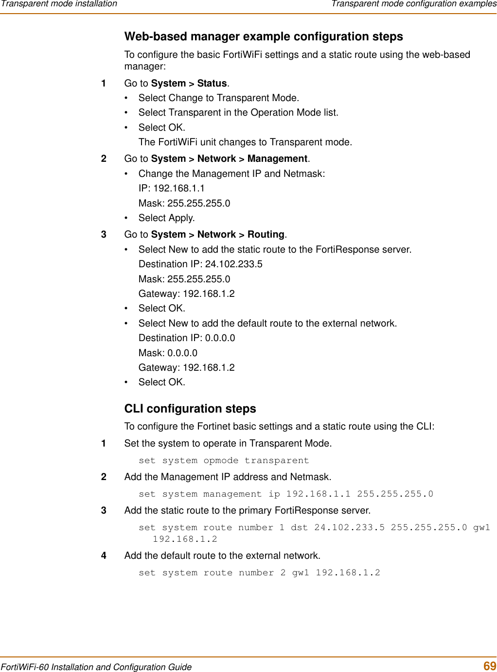
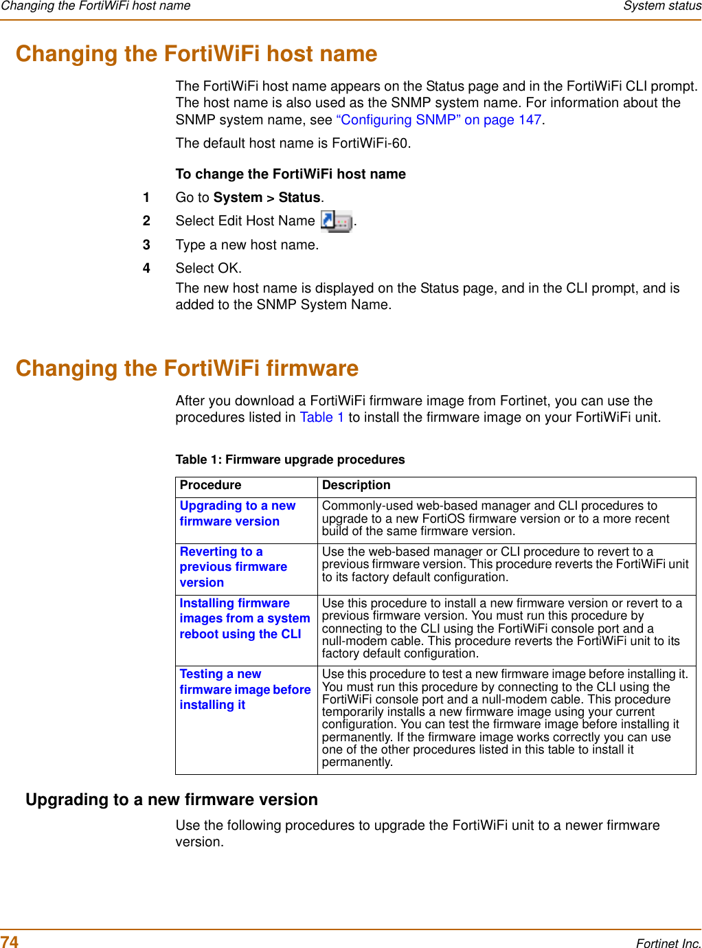
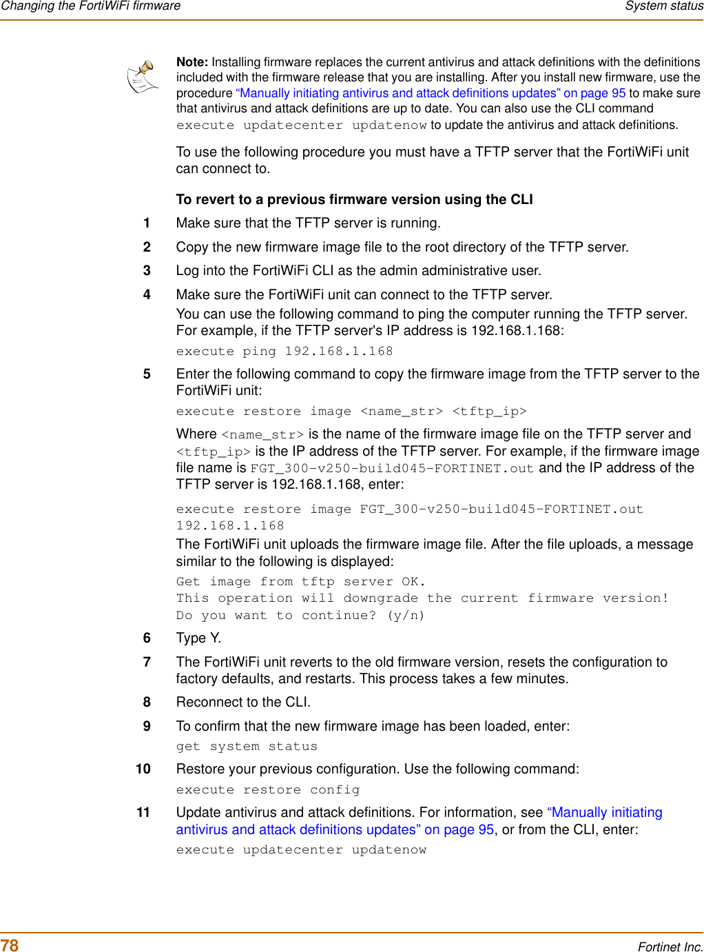
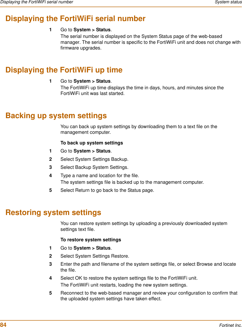
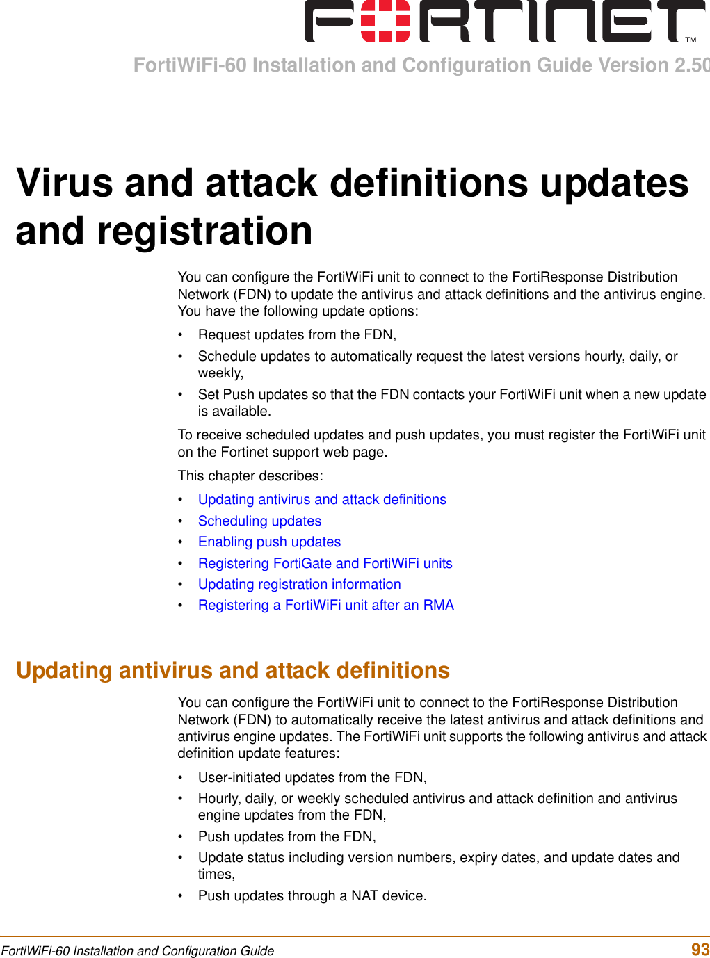
![82 Fortinet Inc.Manual virus definition updates System status6Immediately press any key to interrupt the system startup.If you successfully interrupt the startup process, the following message appears:[G]: Get firmware image from TFTP server.[F]: Format boot device.[Q]: Quit menu and continue to boot with default firmware.[H]: Display this list of options.Enter G,F,Q,or H:7Type G to get the new firmware image from the TFTP server.8Type the address of the TFTP server and press Enter.The following message appears:Enter Local Address [192.168.1.188]:9Type the address of the internal interface of the FortiWiFi unit and press Enter.The following message appears:Enter File Name [image.out]:10 Enter the firmware image file name and press Enter.The TFTP server uploads the firmware image file to the FortiWiFi unit and messages similar to the following appear.Save as Default firmware/Run image without saving:[D/R]11 Type R.The FortiWiFi image is installed to system memory and the FortiWiFi unit starts running the new firmware image but with its current configuration. 12 You can log into the CLI or the web-based manager using any administrative account.13 To confirm that the new firmware image has been loaded, from the CLI enter:get system statusYou can test the new firmware image as required.Manual virus definition updatesThe Status page of the FortiWiFi web-based manager displays the current installed versions of the FortiWiFi antivirus definitions.Note: You have only 3 seconds to press any key. If you do not press a key soon enough, the FortiWiFi unit reboots and you must log in and repeat the execute reboot command.Note: The local IP address is used only to download the firmware image. After the firmware is installed, the address of this interface is changed back to the default IP address for this interface.](https://usermanual.wiki/Fortinet/FORTIWIFI-60.users-manual-1/User-Guide-418740-Page-82.png)
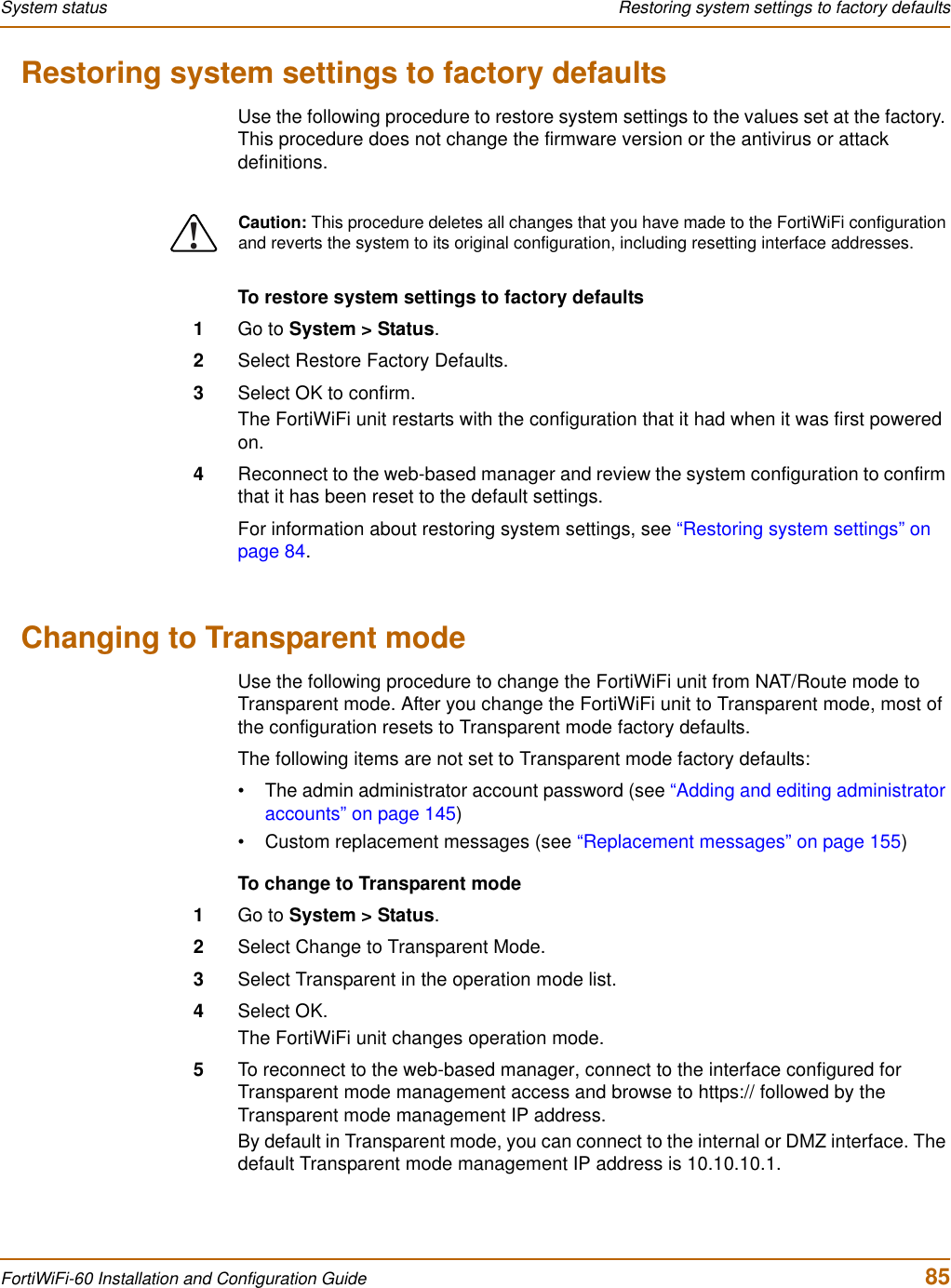

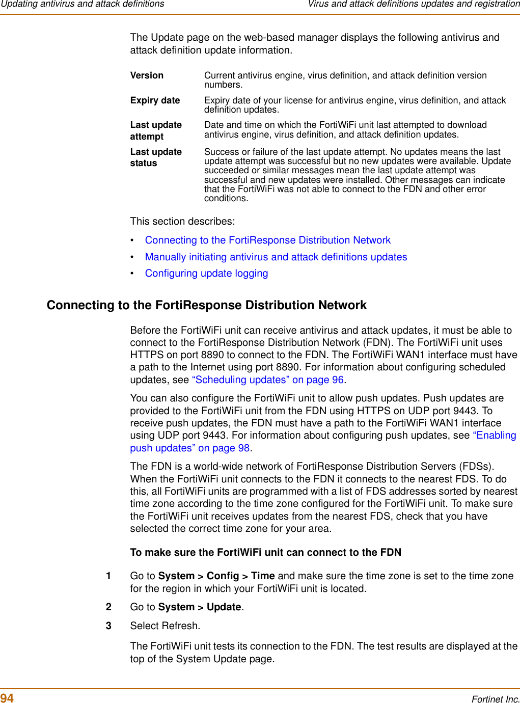
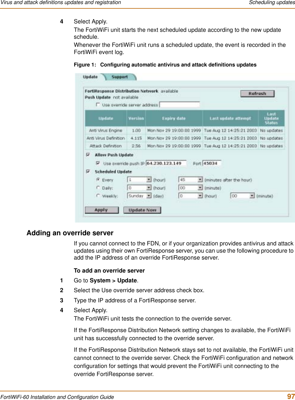
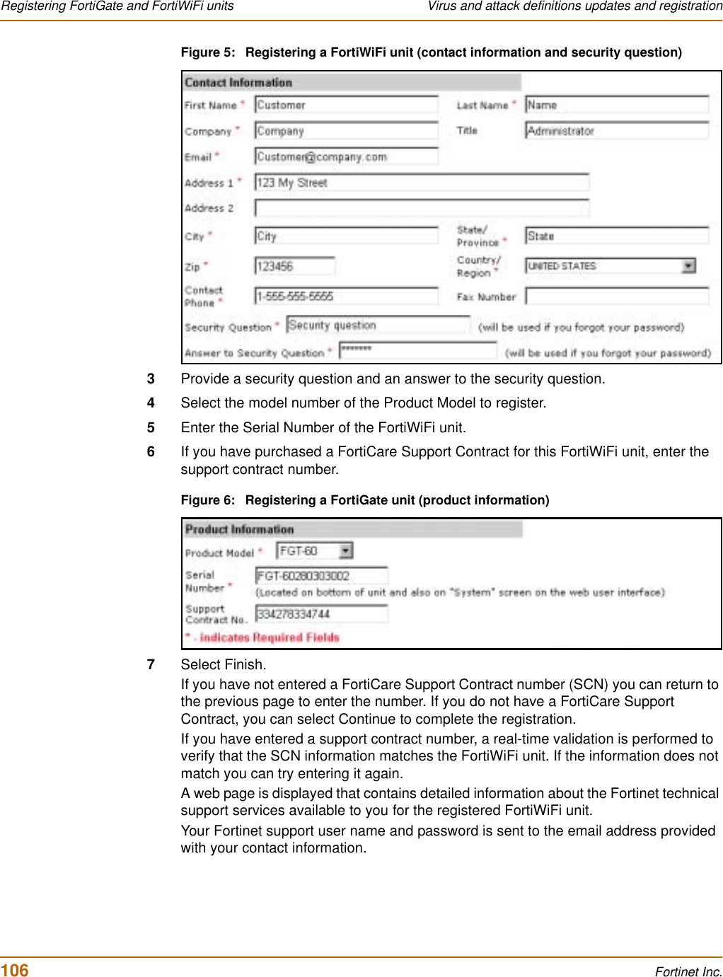
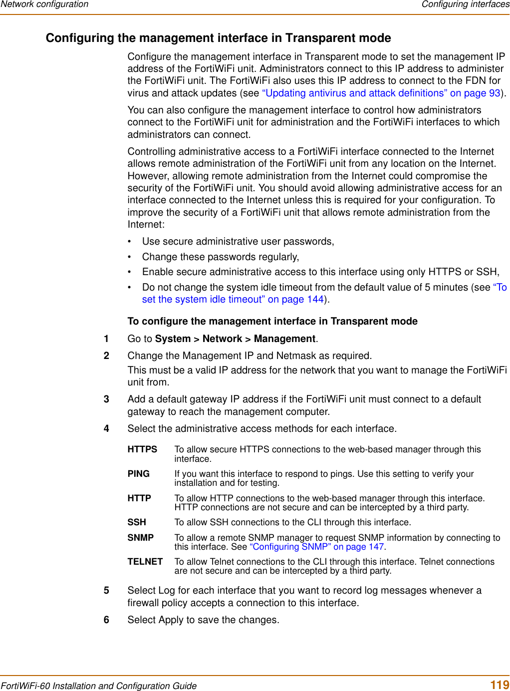
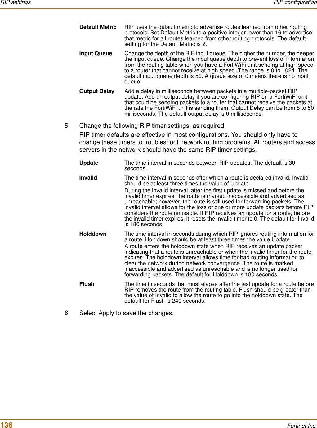
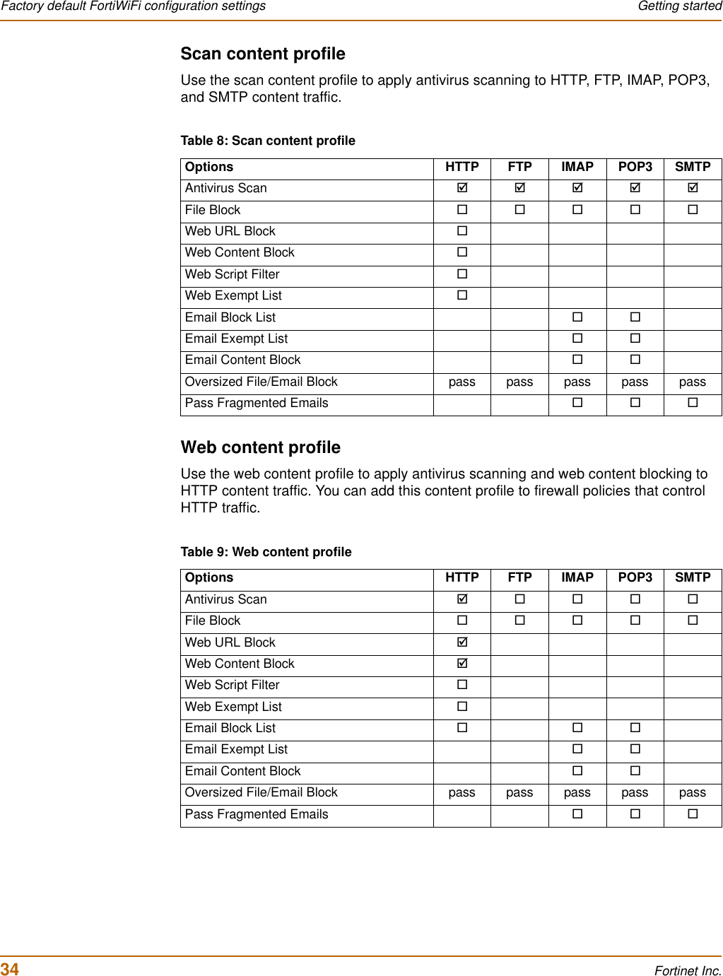
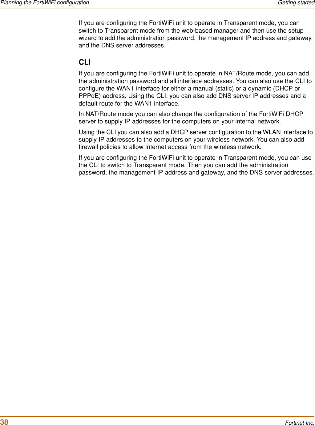
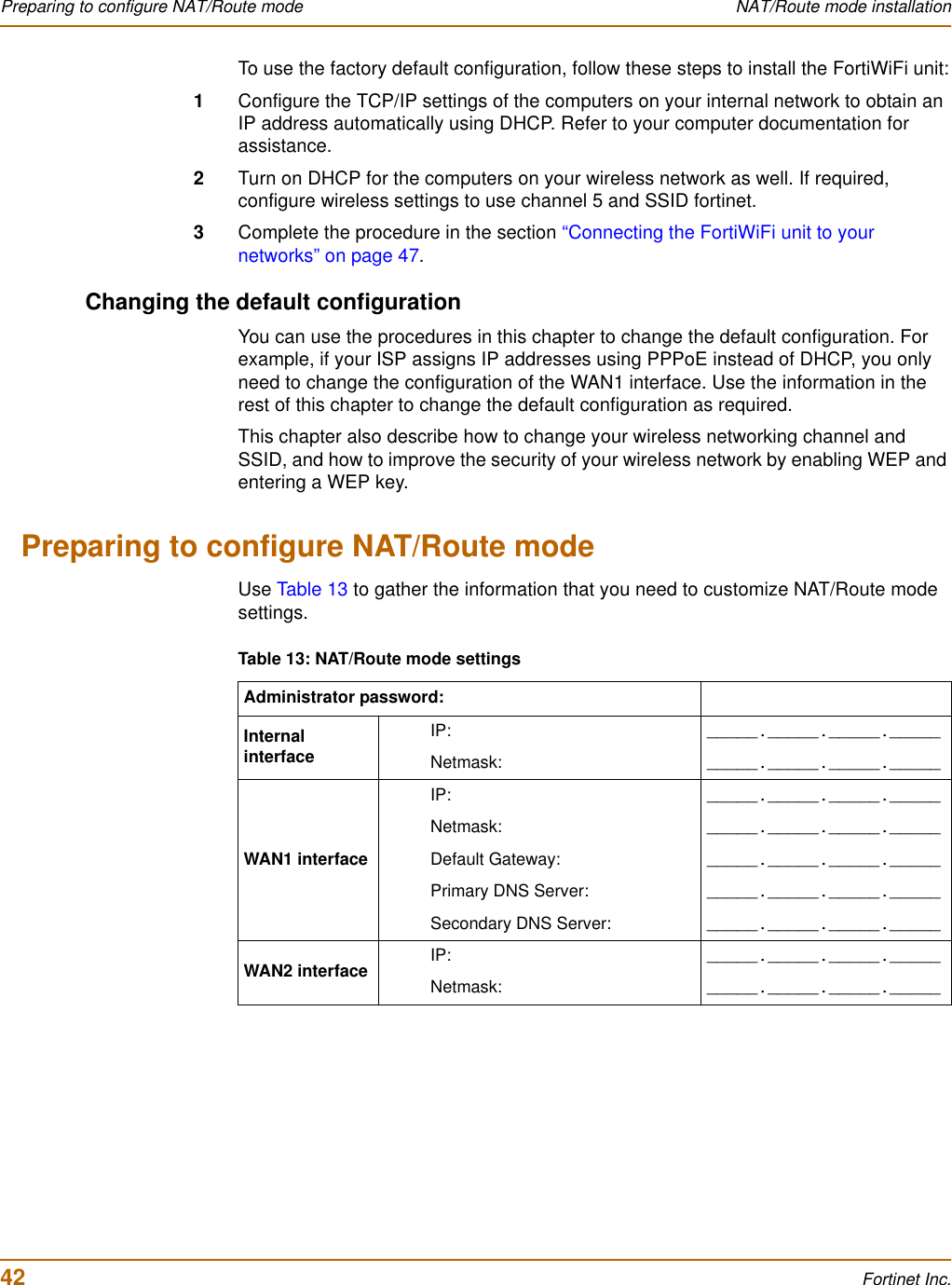
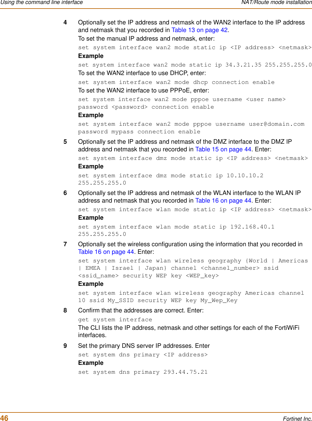
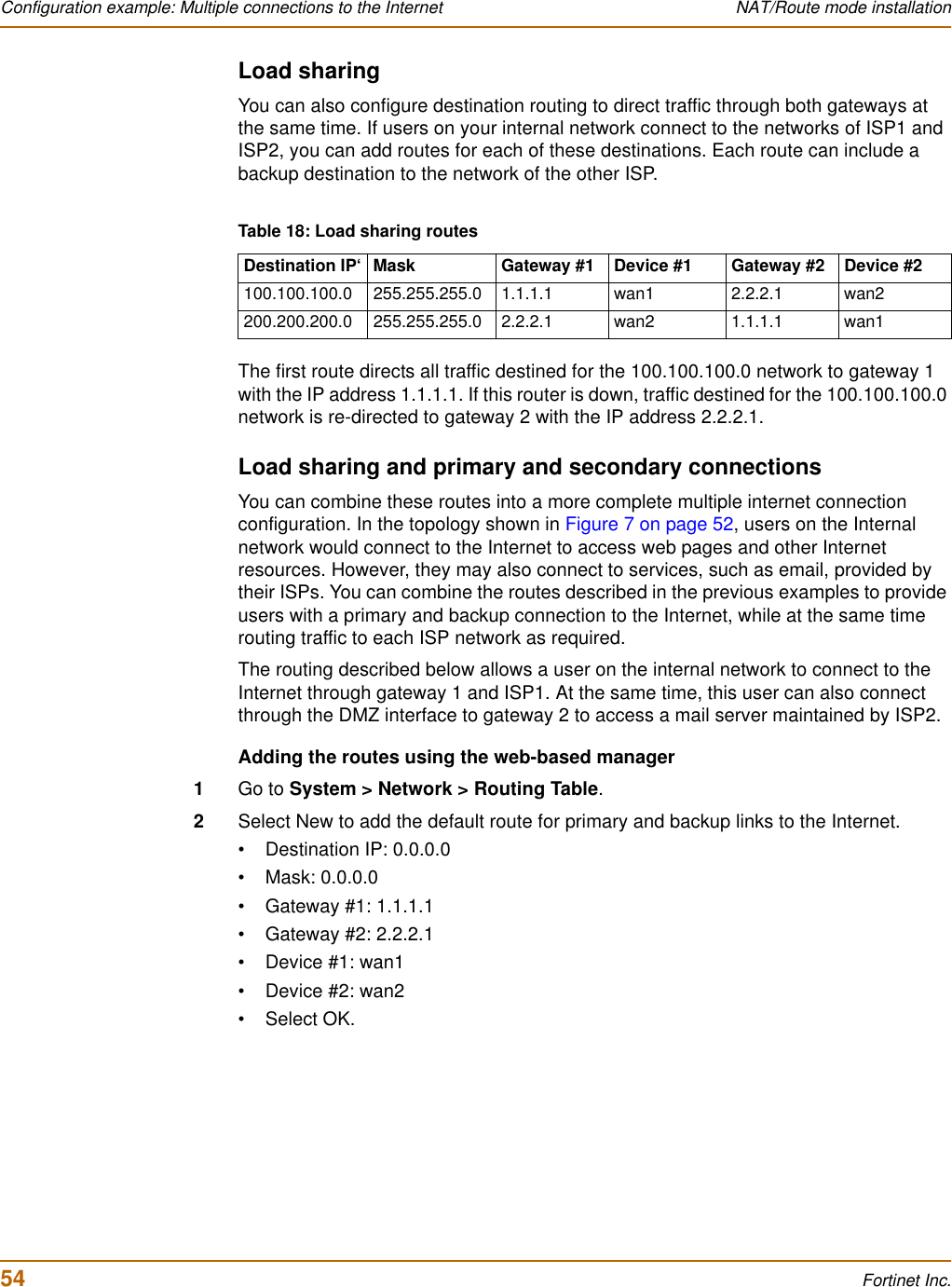
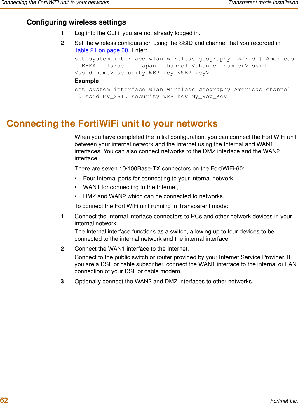
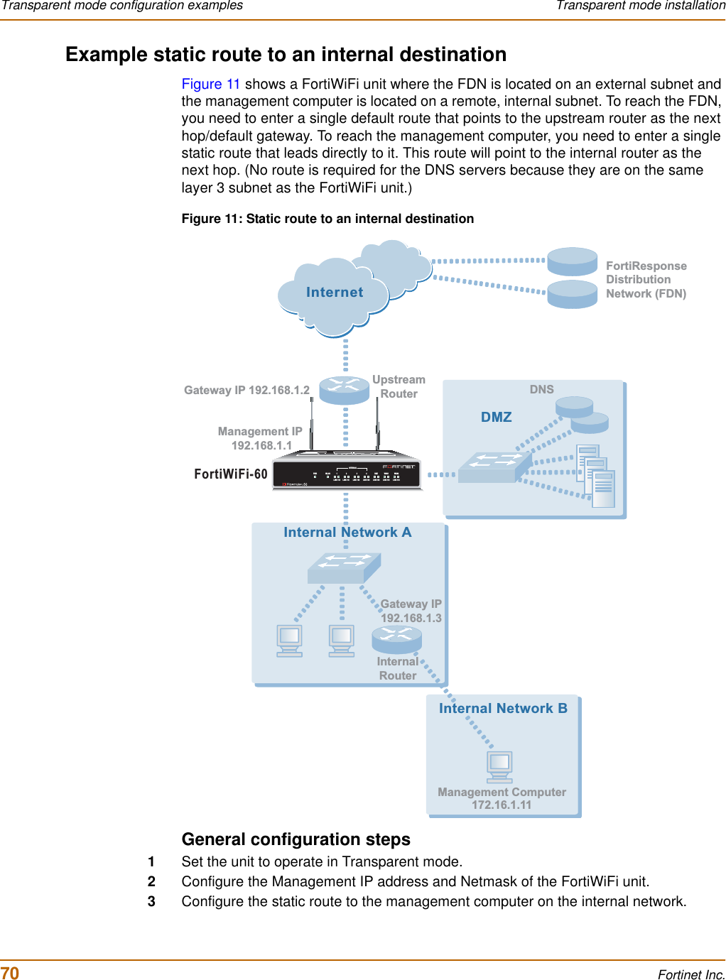
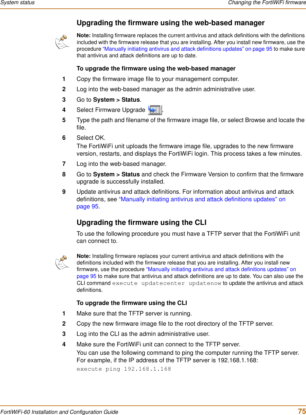
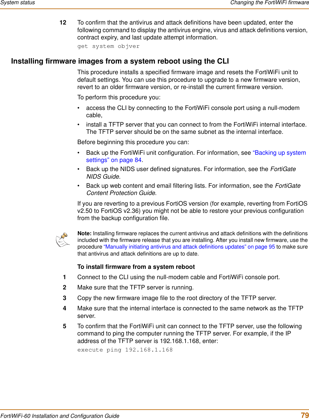
![98 Fortinet Inc.Enabling push updates Virus and attack definitions updates and registrationEnabling scheduled updates through a proxy serverIf your FortiWiFi unit must connect to the Internet through a proxy server, you can use the set system autoupdate tunneling command to allow the FortiWiFi unit to connect (or tunnel) to the FDN using the proxy server. Using this command you can specify the IP address and port of the proxy server. As well, if the proxy server requires authentication, you can add the user name and password required for the proxy server to the autoupdate configuration. The full syntax for enabling updates through a proxy server is:set system autoupdate tunneling enable [address <proxy-address_ip> [port <proxy-port> [username <username_str> [password <password_str>]]]]For example, if the IP address of the proxy server is 64.23.6.89 and its port is 8080, enter the following command:set system autouopdate tunneling enable address 64.23.6.89 port 8080For more information about the set system autoupdate command, see Volume 6, FortiGate CLI Reference Guide.The FortiWiFi unit connects to the proxy server using the HTTP CONNECT method, as described in RFC 2616. The FortiWiFi unit sends an HTTP CONNECT request to the proxy server (optionally with authentication information) specifying the IP address and port required to connect to the FDN. The proxy server establishes the connection to the FDN and passes information between the FortiWiFi unit and the FDN.The CONNECT method is used mostly for tunneling SSL traffic. Some proxy servers do not allow the CONNECT to connect to any port; they restrict the allowed ports to the well known ports for HTTPS and perhaps some other similar services. Because FortiWiFi autoupdates use HTTPS on port 8890 to connect to the FDN, your proxy server might have to be configured to allow connections on this port.There are no special tunneling requirements if you have configured an override server address to connect to the FDN.Enabling push updatesThe FDN can push updates to FortiWiFi units to provide the fastest possible response to critical situations. You must register the FortiWiFi unit before it can receive push updates. See “Registering the FortiWiFi unit” on page 105.When you configure a FortiWiFi unit to allow push updates, the FortiWiFi unit sends a SETUP message to the FDN. The next time a new antivirus engine, new antivirus definitions, or new attack definitions are released, the FDN notifies all FortiWiFi units that are configured for push updates that a new update is available. Within 60 seconds of receiving a push notification, the FortiWiFi unit requests an update from the FDN.Note: Push updates are not supported if the FortiWiFi unit must use a proxy server to connect to the FDN. For more information, see “Enabling scheduled updates through a proxy server” on page 98.](https://usermanual.wiki/Fortinet/FORTIWIFI-60.users-manual-1/User-Guide-418740-Page-98.png)