Fortinet FORTIWIFI-60 Wireless Firewall User Manual Fortinet
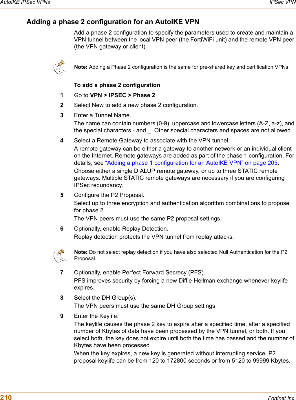
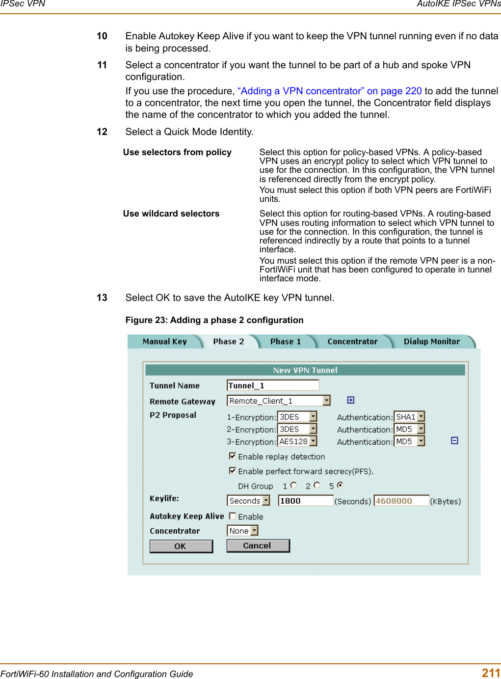
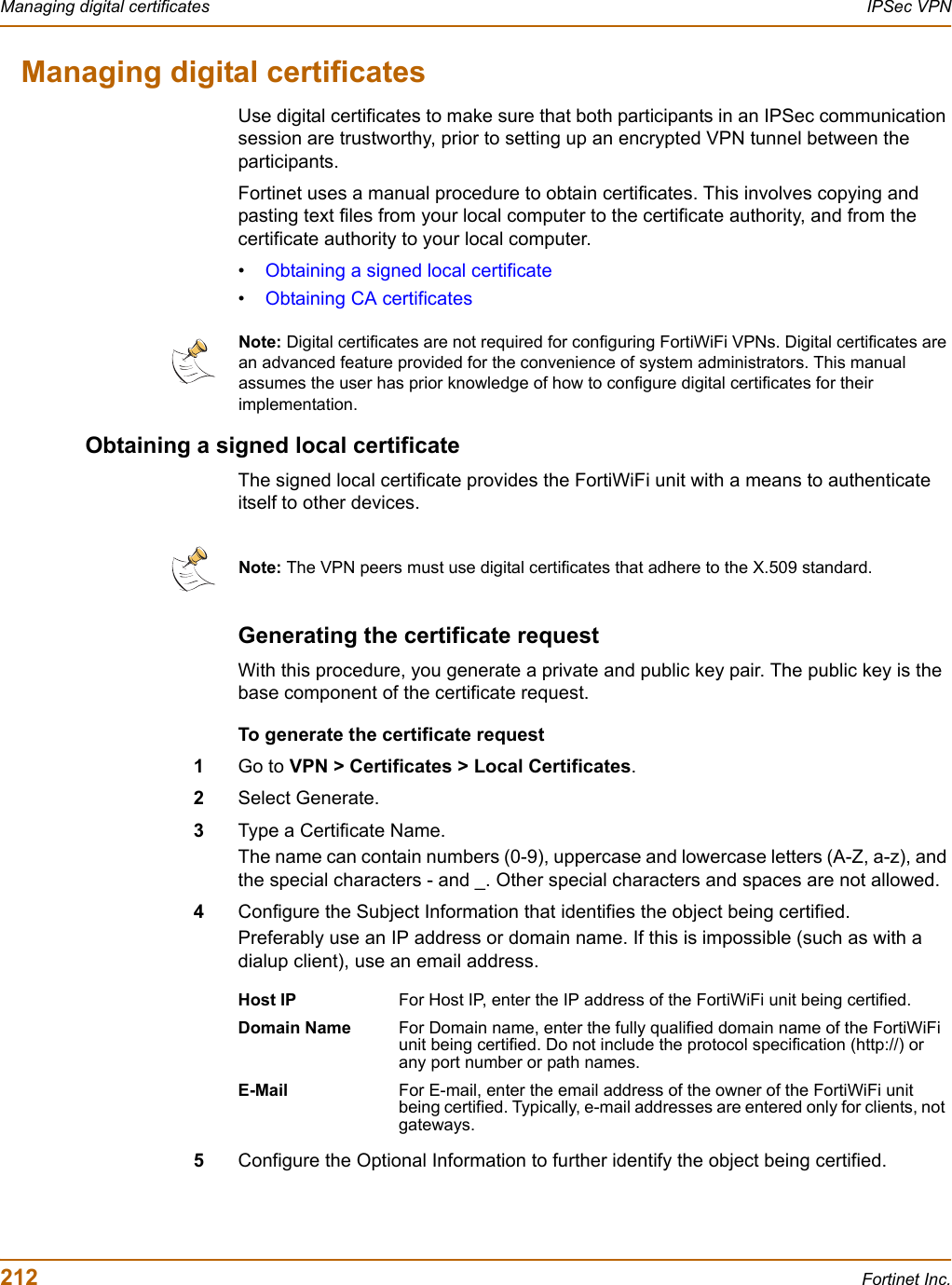
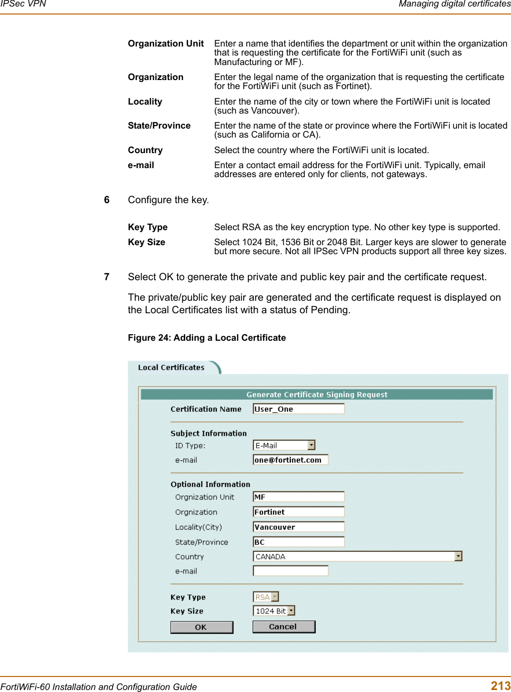
Fortinet, Inc Wireless Firewall Fortinet
UserManual.wiki
>
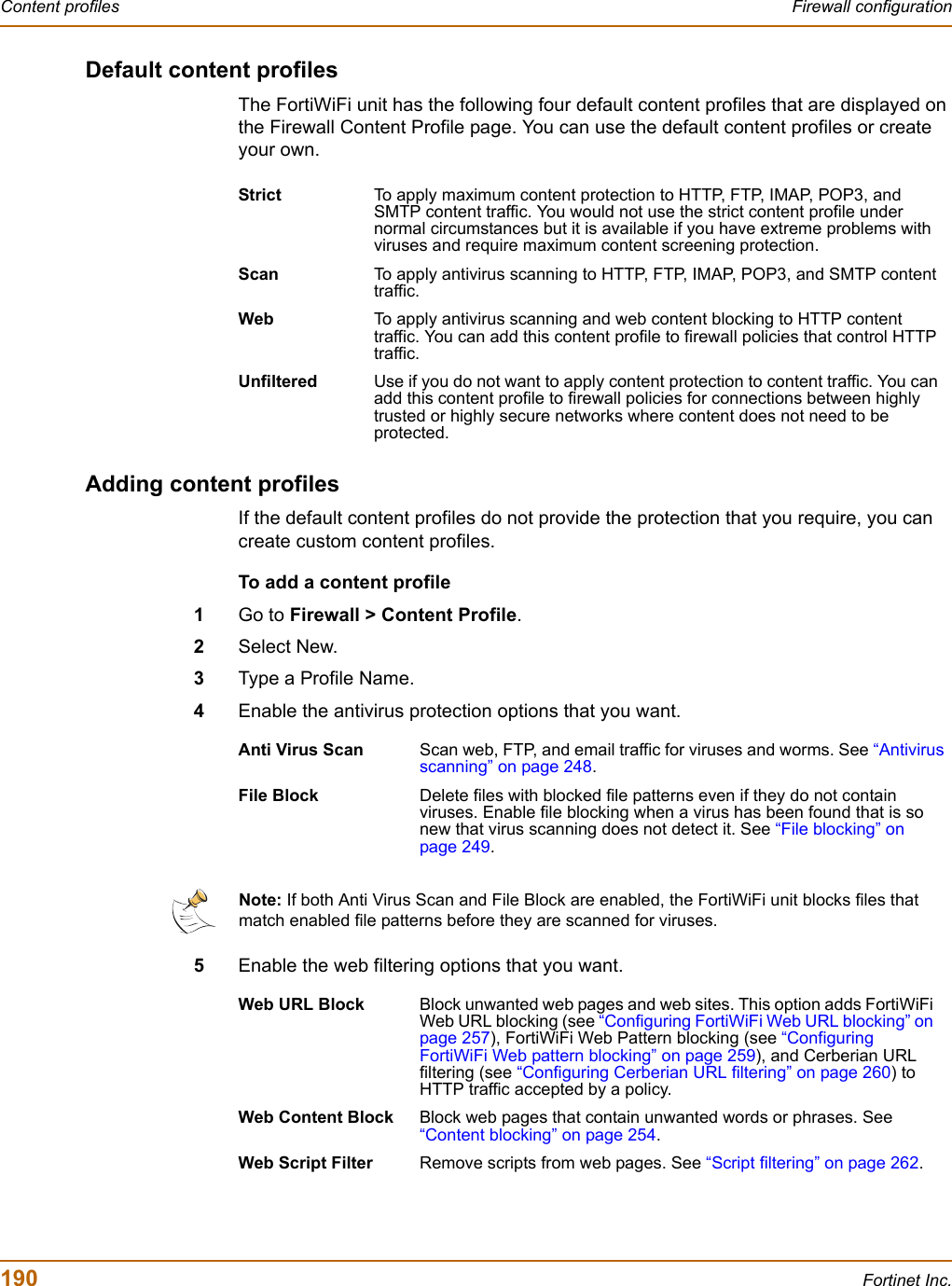
Fortinet
>
FORTIWIFI-60 User Manual
>
users manual 2
Contents
1.
users manual 1
2.
users manual 2
users manual 2
Navigation menu
Upload a User Manual
Namespaces
Wiki Guide
HTML
PDF
Info
Views
User Manual
Discussion / Help
Navigation
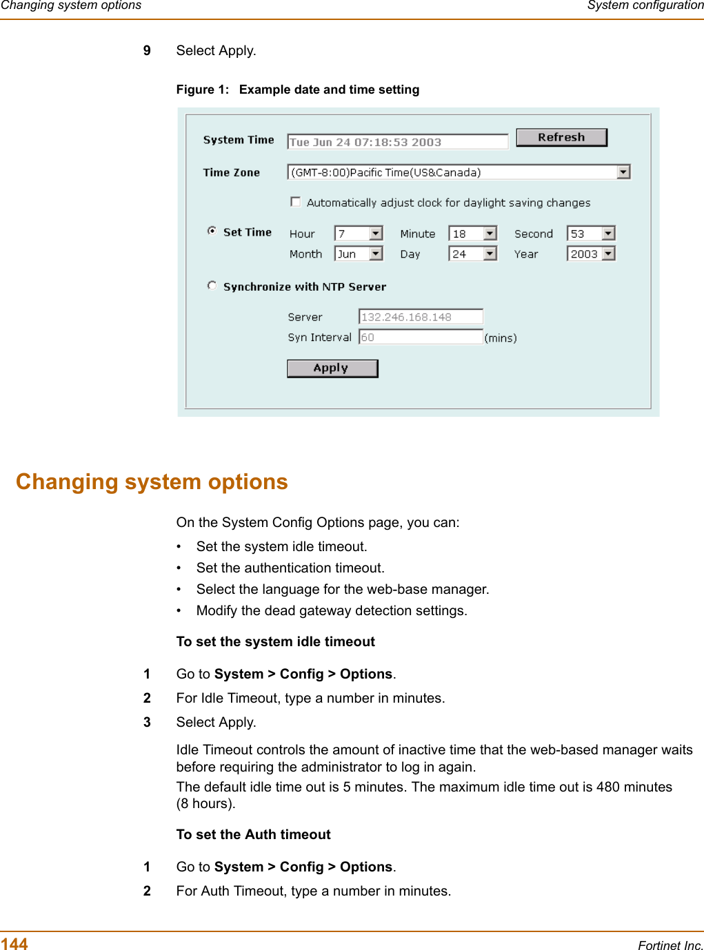
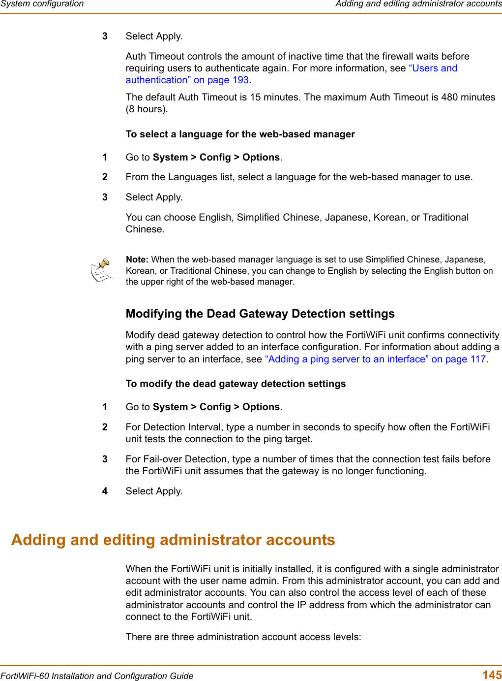
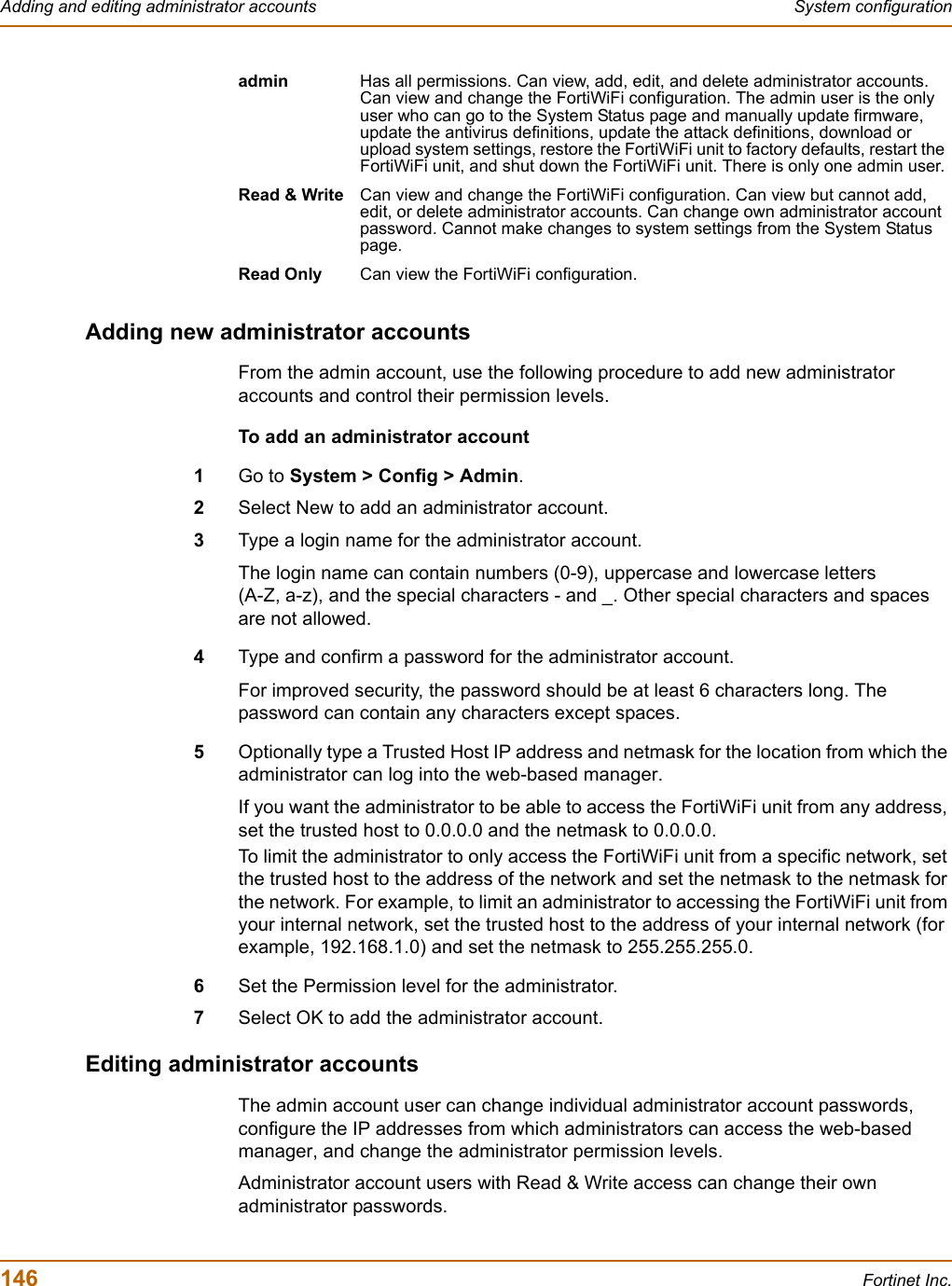
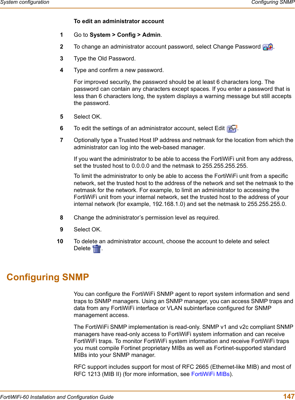
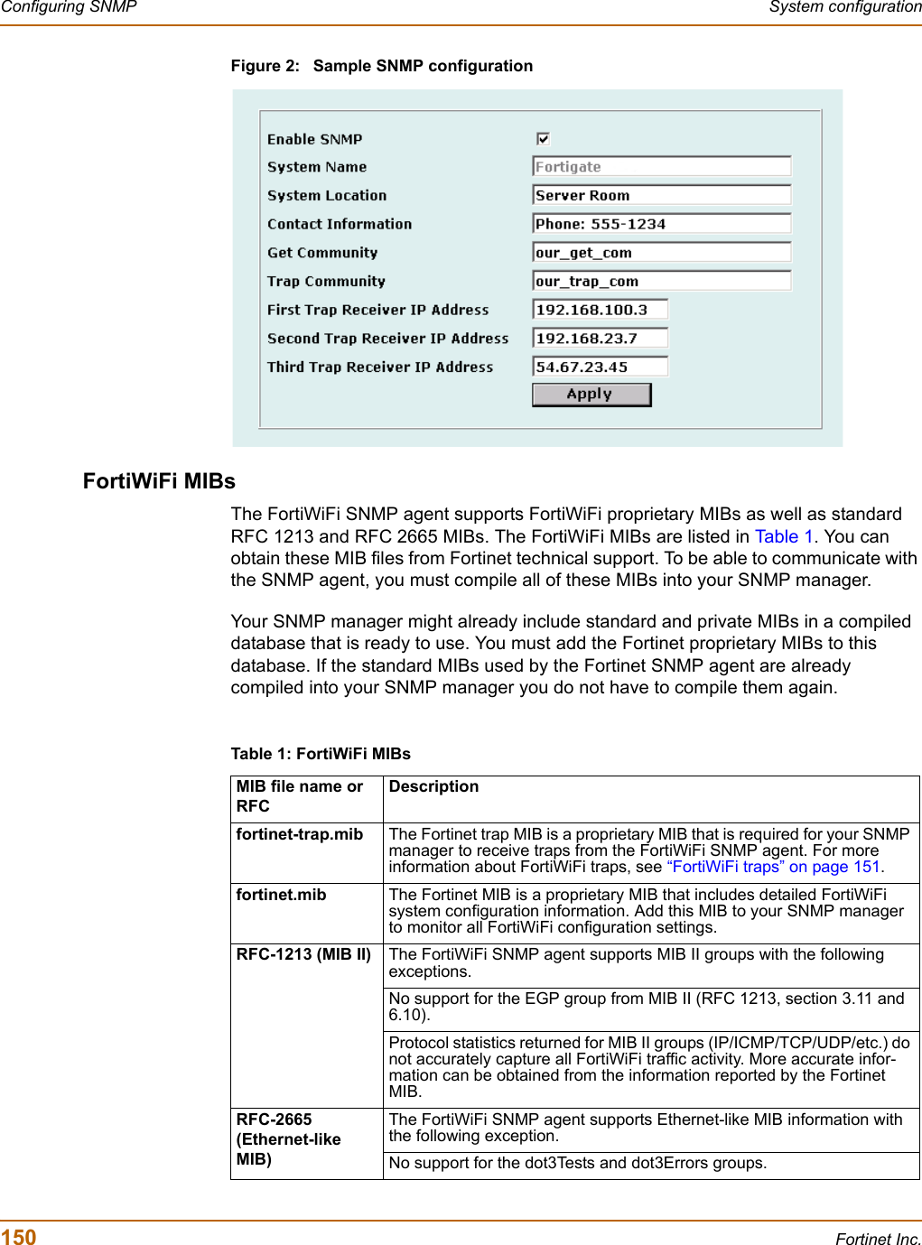
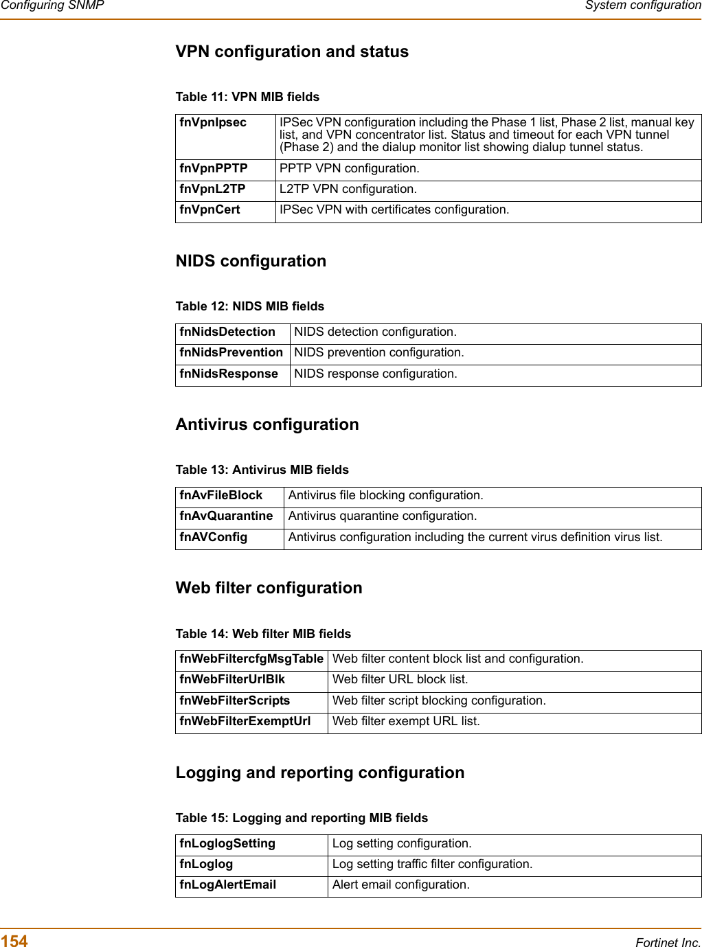
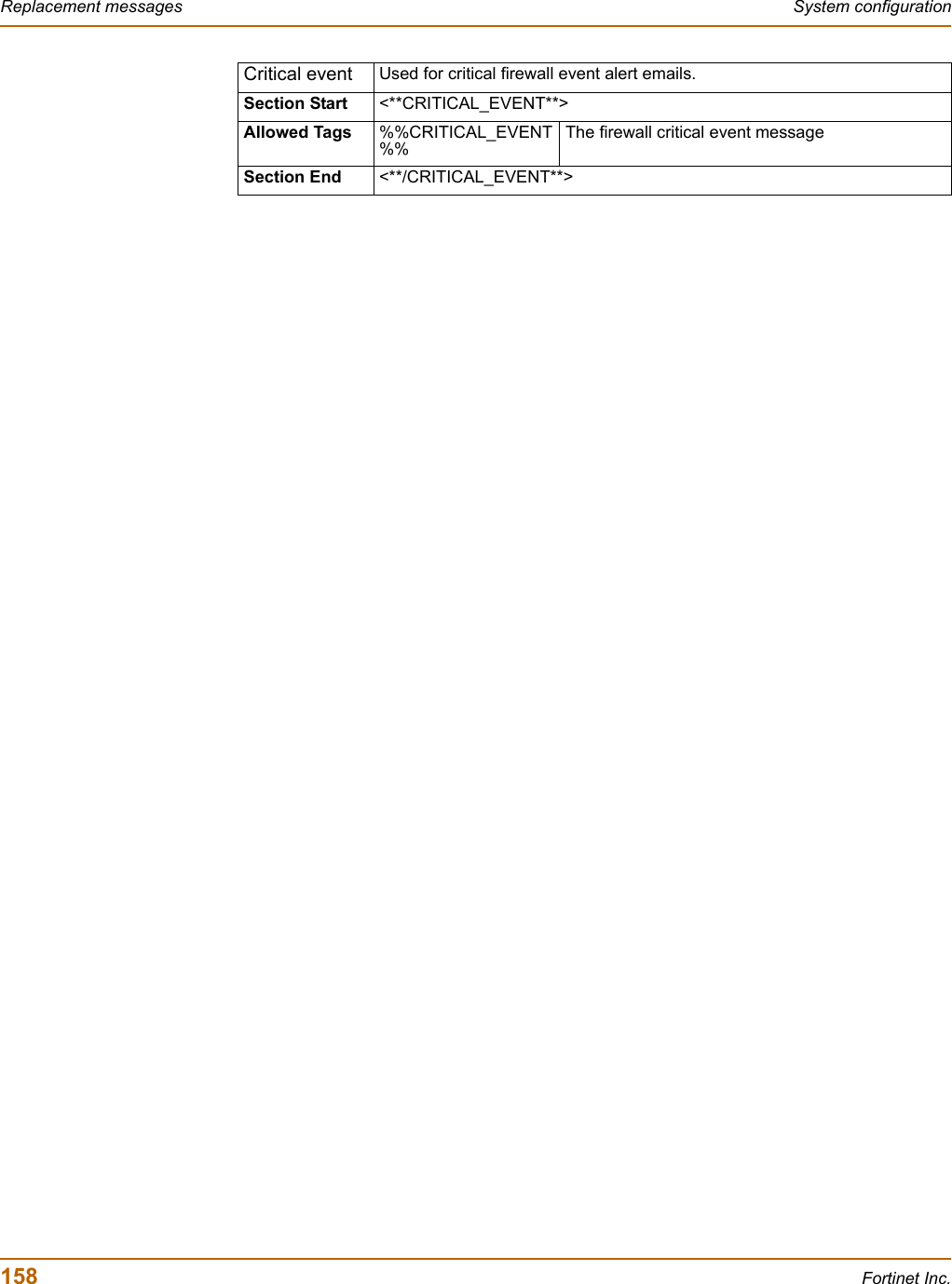
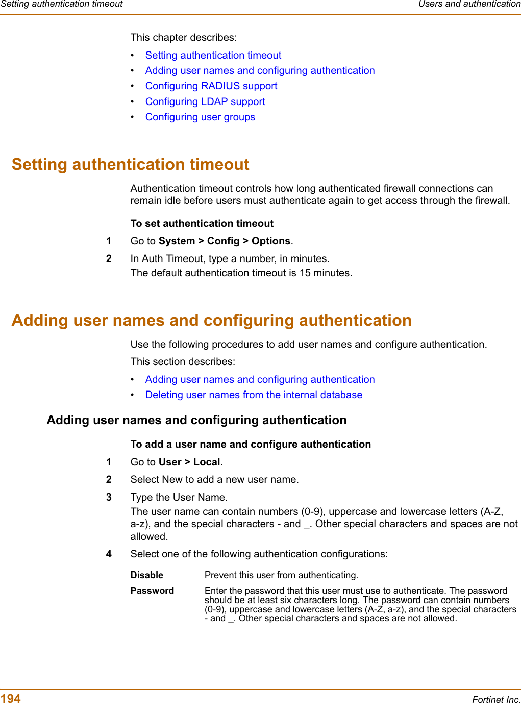
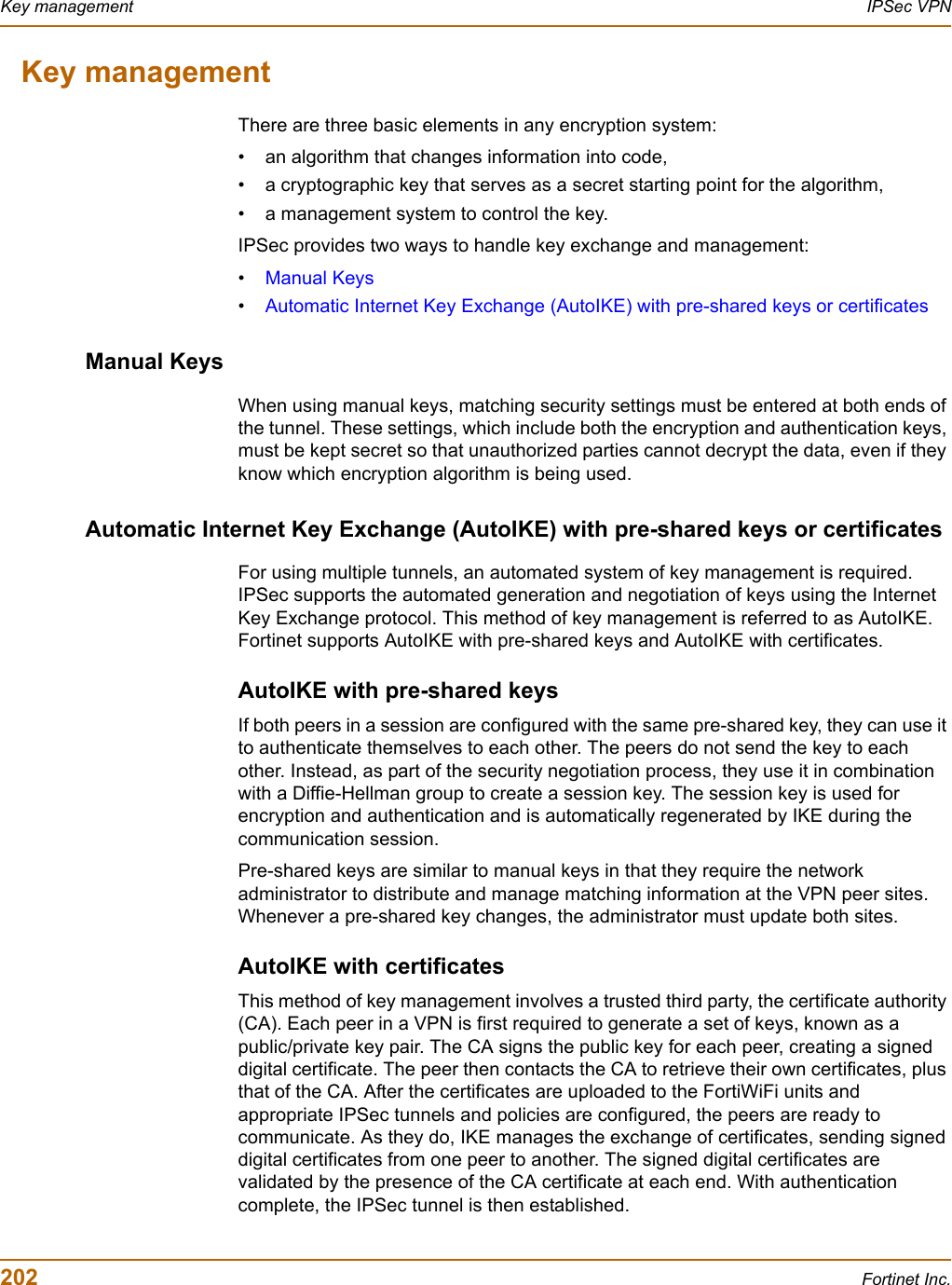
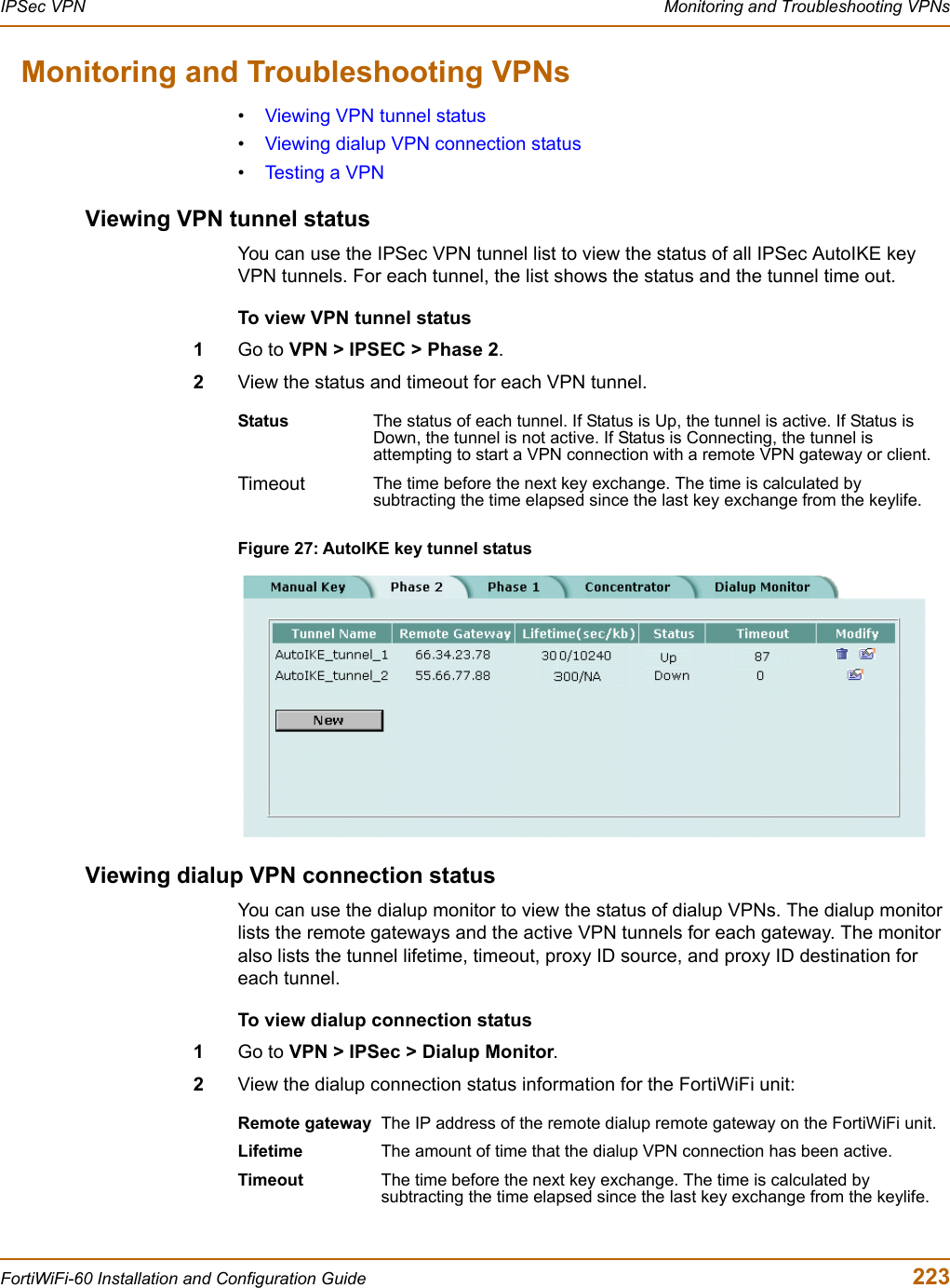
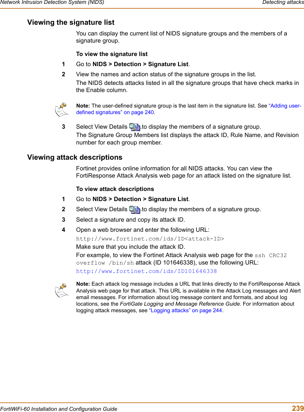
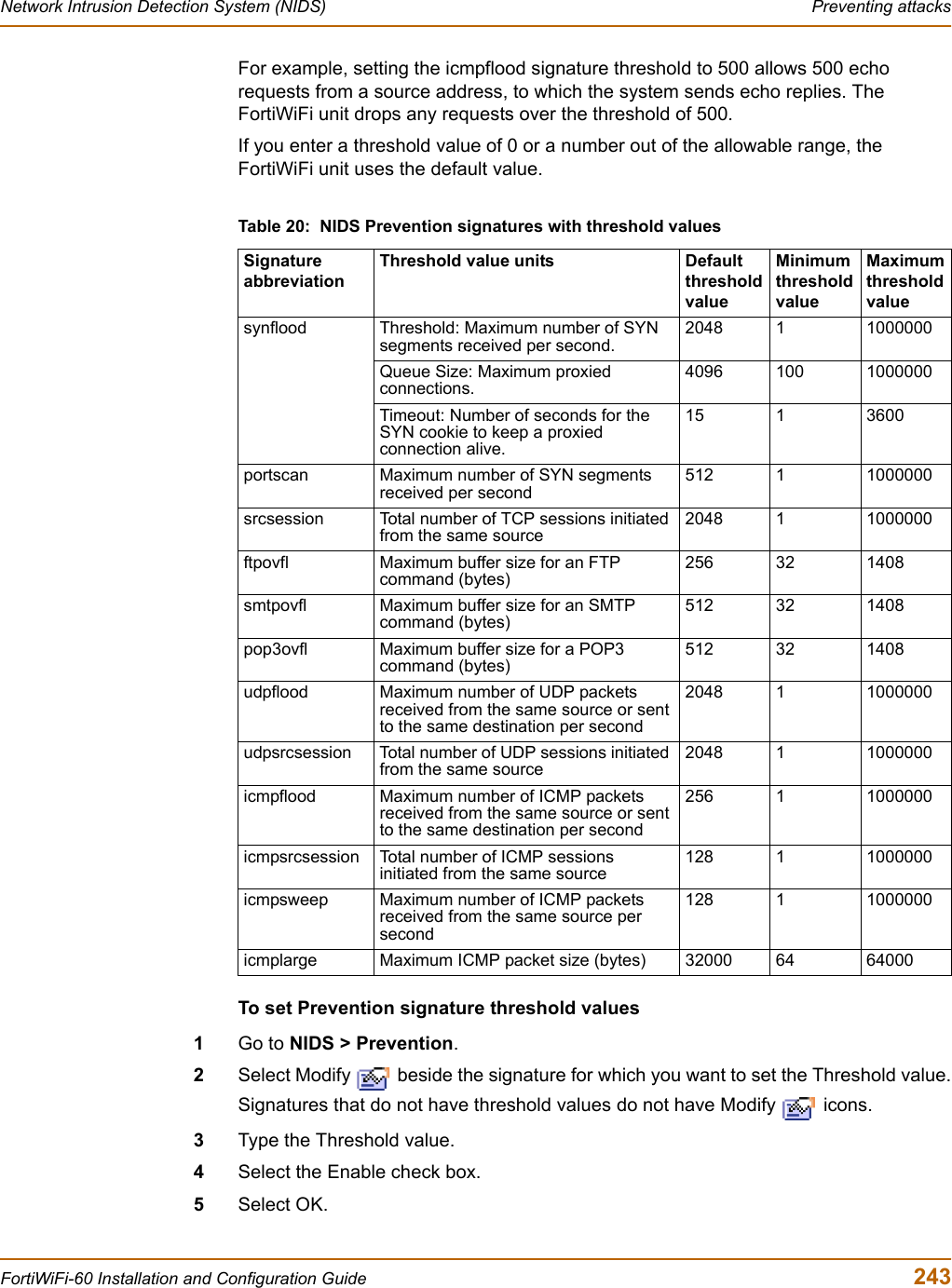
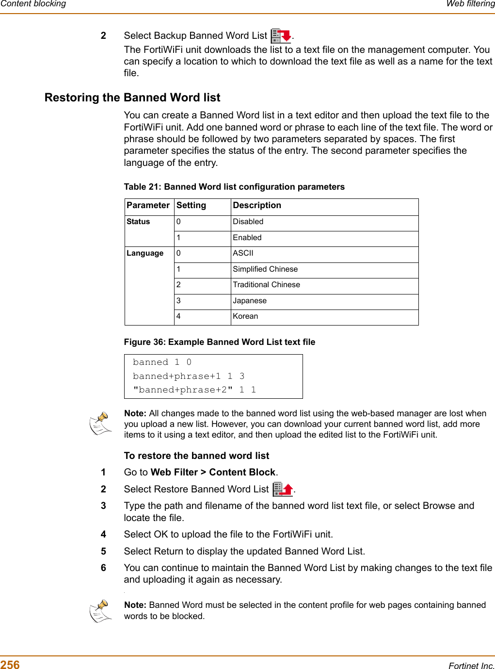
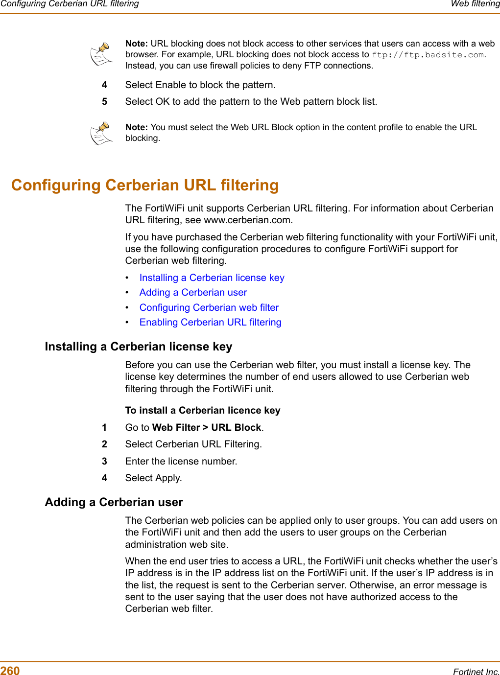
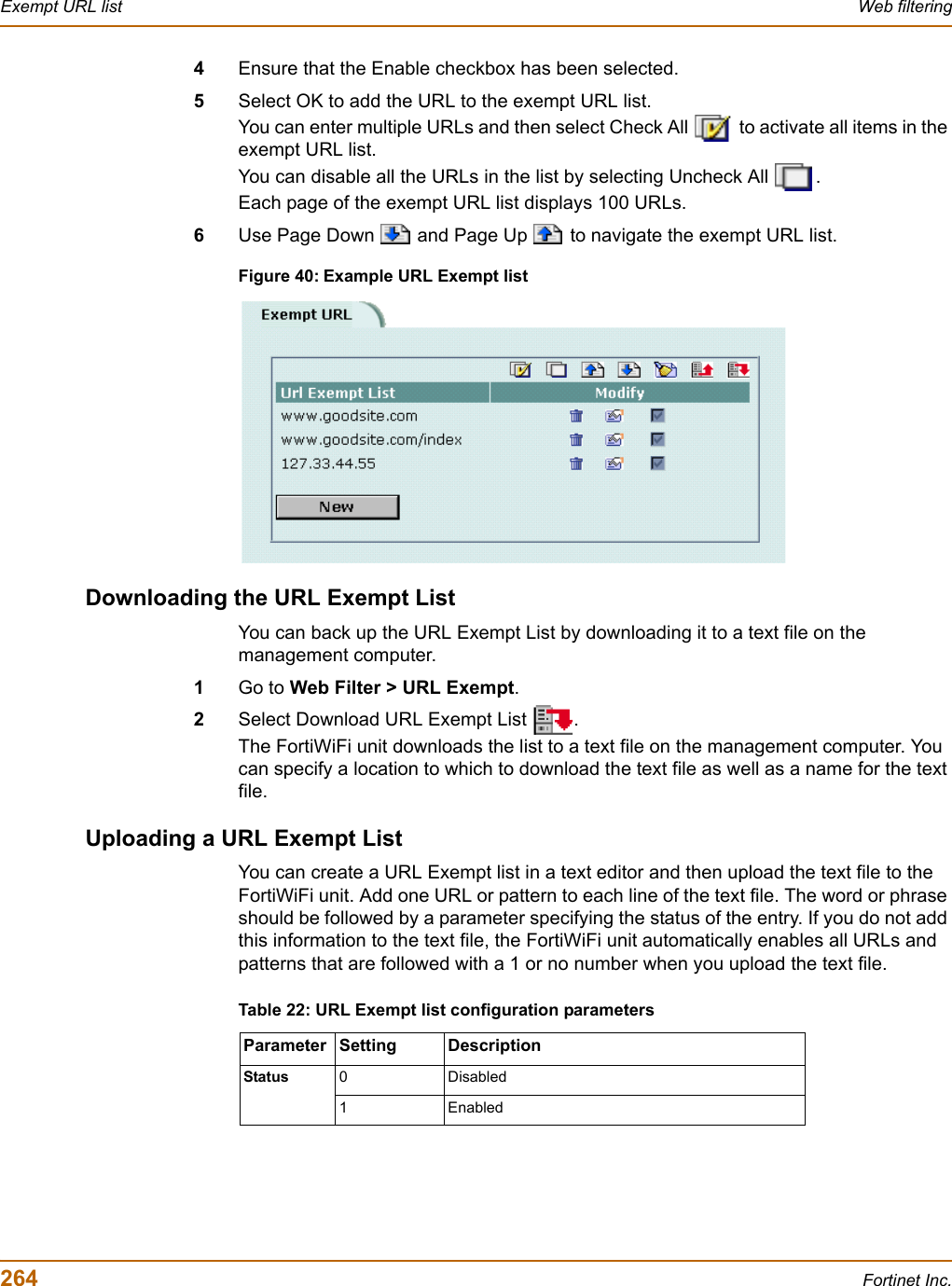
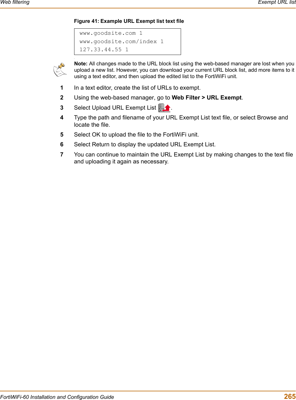
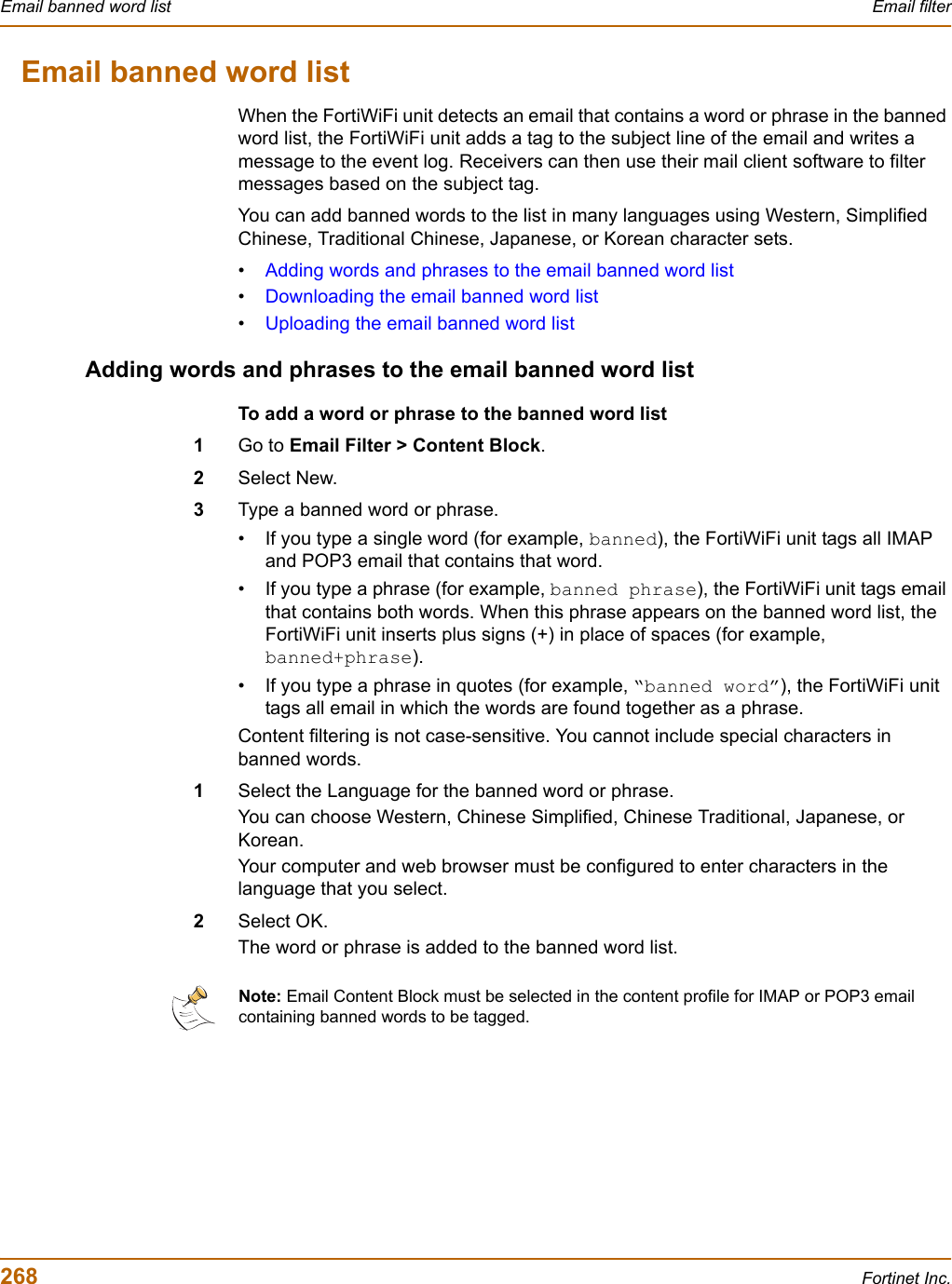
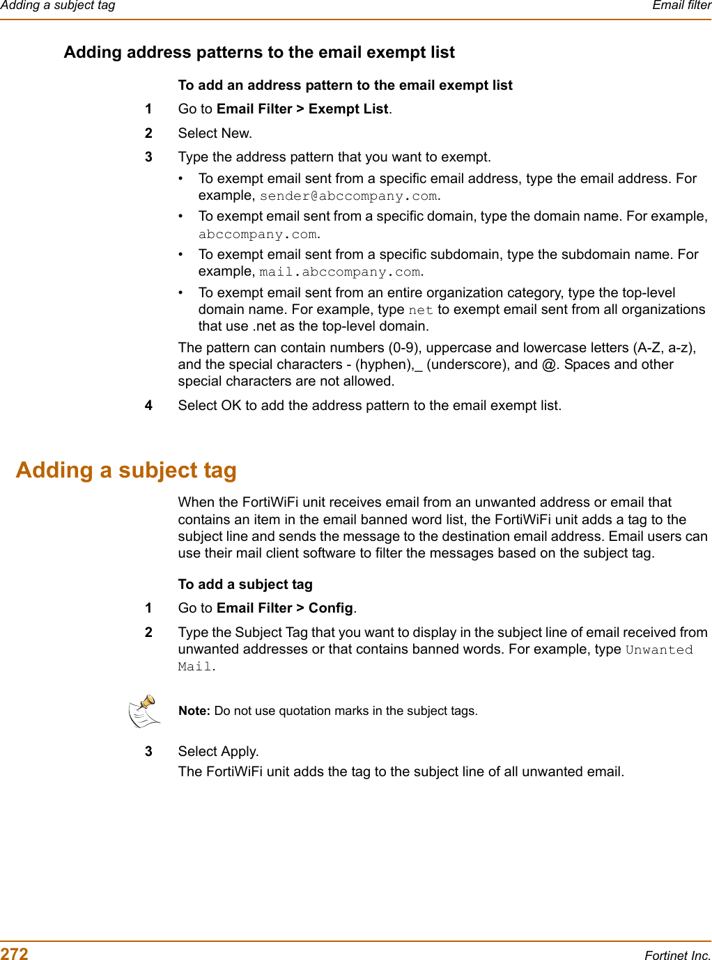
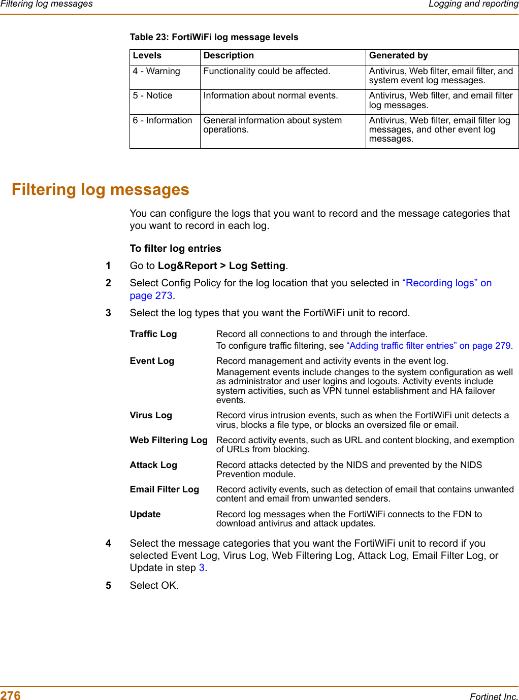
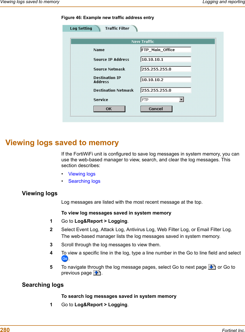
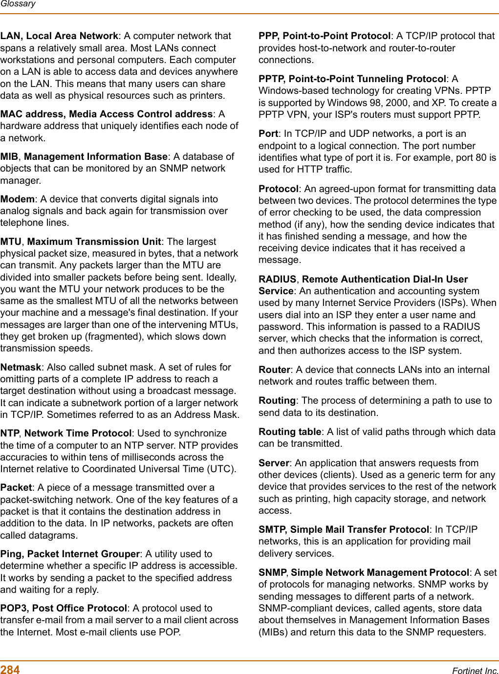
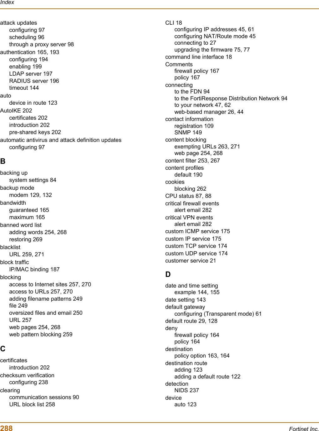
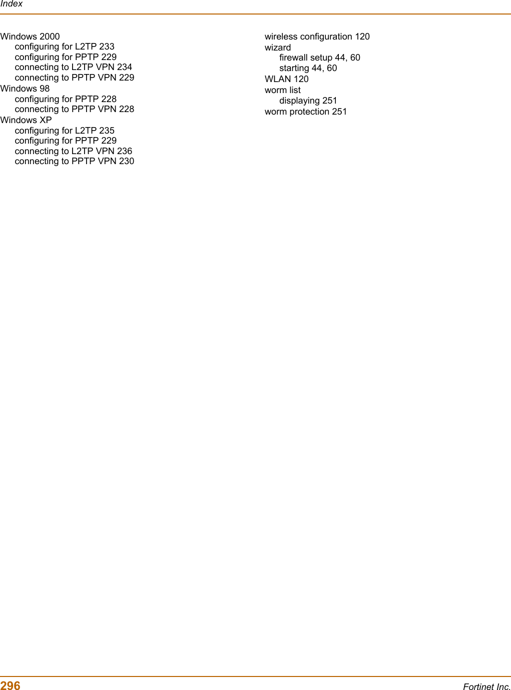
![System configuration Configuring SNMPFortiWiFi-60 Installation and Configuration Guide 149To configure SNMP community settings1Go to System > Config > SNMP v1/v2c.2Select the Enable SNMP check box.3Configure the following SNMP settings:4Select Apply.System Name Automatically set to the FortiWiFi host name. To change the System Name, see “Changing the FortiWiFi host name” on page 74.System Location Describe the physical location of the FortiWiFi unit. The system location description can be up to 31 characters long and can contain spaces, numbers (0-9), uppercase and lowercase letters (A-Z, a-z), and the special characters - and _. The \ < > [ ] ` $ % & characters are not allowed.Contact Information Add the contact information for the person responsible for this FortiWiFi unit. The contact information can be up to 31 characters long and can contain spaces, numbers (0-9), uppercase and lowercase letters (A-Z, a-z), and the special characters - and _. The \ < > [ ] ` $ % & characters are not allowed.Get Community Also called read community, get community is a password to identify SNMP get requests sent to the FortiWiFi unit. When an SNMP manager sends a get request to the FortiWiFi unit, it must include the correct get community string.The default get community string is “public”. Change the default get community string to keep intruders from using get requests to retrieve information about your network configuration. The get community string must be used in your SNMP manager to enable it to access FortiWiFi SNMP information.The get community string can be up to 31 characters long and can contain numbers (0-9), uppercase and lowercase letters (A-Z, a-z), and the special characters - and _. Spaces and the \ < > [ ] ` $ % & characters are not allowed.Trap Community The trap community string functions like a password that is sent with SNMP traps.The default trap community string is “public”. Change the trap community string to the one accepted by your trap receivers.The trap community string can be up to 31 characters long and can contain numbers (0-9), uppercase and lowercase letters (A-Z, a-z), and the special characters - and _. Spaces and the \ < > [ ] ` $ % & characters are not allowed.Trap Receiver IP AddressesType the IP addresses of up to three trap receivers on your network that are configured to receive traps from your FortiWiFi unit. Traps are only sent to the configured addresses.](https://usermanual.wiki/Fortinet/FORTIWIFI-60.users-manual-2/User-Guide-418741-Page-9.png)