Fortinet FORTIWIFI-60 Wireless Firewall User Manual Fortinet
Fortinet, Inc Wireless Firewall Fortinet
Fortinet >
Contents
- 1. users manual 1
- 2. users manual 2
users manual 2

RIP configuration Adding RIP filters
FortiWiFi-60 Installation and Configuration Guide 141
Assigning a RIP filter list to the outgoing filter
The outgoing filter allows or denies adding routes to outgoing RIP update packets.
You can assign a single RIP filter list to the outgoing filter.
To assign a RIP filter list to the outgoing filter
1Go to System > RIP > Filter.
2Add RIP filter lists as required.
3For Outgoing Routes Filter, select the name of the RIP filter list to assign to the
outgoing filter.
4Select Apply.

142 Fortinet Inc.
Adding RIP filters RIP configuration

FortiWiFi-60 Installation and Configuration Guide Version 2.50
FortiWiFi-60 Installation and Configuration Guide 143
System configuration
Use the System Config page to make any of the following changes to the FortiWiFi
system configuration:
•Setting system date and time
•Changing system options
•Adding and editing administrator accounts
•Configuring SNMP
•Replacement messages
Setting system date and time
For effective scheduling and logging, the FortiWiFi system time must be accurate. You
can either manually set the FortiWiFi system time or you can configure the FortiWiFi
unit to automatically keep its system time correct by synchronizing with a Network
Time Protocol (NTP) server.
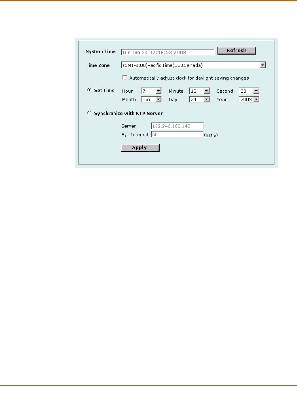
To set the date and time
1Go to System > Config > Time.
2Select Refresh to display the current FortiWiFi system date and time.
3Select your Time Zone from the list.
4Select the Automatically adjust clock for daylight saving changes check box if you
want the FortiWiFi system clock to be adjusted automatically when your time zone
changes to daylight saving time.
5Select Set Time and set the FortiWiFi system date and time to the correct date and
time, if required.
6Select Synchronize with NTP Server to configure the FortiWiFi unit to use NTP to
automatically set the system time and date.
For more information about NTP and to find the IP address of an NTP server that you
can use, see http://www.ntp.org.
7Enter the IP address or domain name of the NTP server that the FortiWiFi unit can
use to set its time and date.
8Specify how often the FortiWiFi unit should synchronize its time with the NTP server. A
typical Syn Interval would be 1440 minutes for the FortiWiFi unit to synchronize its
time once a day.
144 Fortinet Inc.
Changing system options System configuration
9Select Apply.
Figure 1: Example date and time setting
Changing system options
On the System Config Options page, you can:
• Set the system idle timeout.
• Set the authentication timeout.
• Select the language for the web-base manager.
• Modify the dead gateway detection settings.
To set the system idle timeout
1Go to System > Config > Options.
2For Idle Timeout, type a number in minutes.
3Select Apply.
Idle Timeout controls the amount of inactive time that the web-based manager waits
before requiring the administrator to log in again.
The default idle time out is 5 minutes. The maximum idle time out is 480 minutes
(8 hours).
To set the Auth timeout
1Go to System > Config > Options.
2For Auth Timeout, type a number in minutes.

System configuration Adding and editing administrator accounts
FortiWiFi-60 Installation and Configuration Guide 145
3Select Apply.
Auth Timeout controls the amount of inactive time that the firewall waits before
requiring users to authenticate again. For more information, see “Users and
authentication” on page 193.
The default Auth Timeout is 15 minutes. The maximum Auth Timeout is 480 minutes
(8 hours).
To select a language for the web-based manager
1Go to System > Config > Options.
2From the Languages list, select a language for the web-based manager to use.
3Select Apply.
You can choose English, Simplified Chinese, Japanese, Korean, or Traditional
Chinese.
Modifying the Dead Gateway Detection settings
Modify dead gateway detection to control how the FortiWiFi unit confirms connectivity
with a ping server added to an interface configuration. For information about adding a
ping server to an interface, see “Adding a ping server to an interface” on page 117.
To modify the dead gateway detection settings
1Go to System > Config > Options.
2For Detection Interval, type a number in seconds to specify how often the FortiWiFi
unit tests the connection to the ping target.
3For Fail-over Detection, type a number of times that the connection test fails before
the FortiWiFi unit assumes that the gateway is no longer functioning.
4Select Apply.
Adding and editing administrator accounts
When the FortiWiFi unit is initially installed, it is configured with a single administrator
account with the user name admin. From this administrator account, you can add and
edit administrator accounts. You can also control the access level of each of these
administrator accounts and control the IP address from which the administrator can
connect to the FortiWiFi unit.
There are three administration account access levels:
Note: When the web-based manager language is set to use Simplified Chinese, Japanese,
Korean, or Traditional Chinese, you can change to English by selecting the English button on
the upper right of the web-based manager.

146 Fortinet Inc.
Adding and editing administrator accounts System configuration
Adding new administrator accounts
From the admin account, use the following procedure to add new administrator
accounts and control their permission levels.
To add an administrator account
1Go to System > Config > Admin.
2Select New to add an administrator account.
3Type a login name for the administrator account.
The login name can contain numbers (0-9), uppercase and lowercase letters
(A-Z, a-z), and the special characters - and _. Other special characters and spaces
are not allowed.
4Type and confirm a password for the administrator account.
For improved security, the password should be at least 6 characters long. The
password can contain any characters except spaces.
5Optionally type a Trusted Host IP address and netmask for the location from which the
administrator can log into the web-based manager.
If you want the administrator to be able to access the FortiWiFi unit from any address,
set the trusted host to 0.0.0.0 and the netmask to 0.0.0.0.
To limit the administrator to only access the FortiWiFi unit from a specific network, set
the trusted host to the address of the network and set the netmask to the netmask for
the network. For example, to limit an administrator to accessing the FortiWiFi unit from
your internal network, set the trusted host to the address of your internal network (for
example, 192.168.1.0) and set the netmask to 255.255.255.0.
6Set the Permission level for the administrator.
7Select OK to add the administrator account.
Editing administrator accounts
The admin account user can change individual administrator account passwords,
configure the IP addresses from which administrators can access the web-based
manager, and change the administrator permission levels.
Administrator account users with Read & Write access can change their own
administrator passwords.
admin Has all permissions. Can view, add, edit, and delete administrator accounts.
Can view and change the FortiWiFi configuration. The admin user is the only
user who can go to the System Status page and manually update firmware,
update the antivirus definitions, update the attack definitions, download or
upload system settings, restore the FortiWiFi unit to factory defaults, restart the
FortiWiFi unit, and shut down the FortiWiFi unit. There is only one admin user.
Read & Write Can view and change the FortiWiFi configuration. Can view but cannot add,
edit, or delete administrator accounts. Can change own administrator account
password. Cannot make changes to system settings from the System Status
page.
Read Only Can view the FortiWiFi configuration.

System configuration Configuring SNMP
FortiWiFi-60 Installation and Configuration Guide 147
To edit an administrator account
1Go to System > Config > Admin.
2To change an administrator account password, select Change Password .
3Type the Old Password.
4Type and confirm a new password.
For improved security, the password should be at least 6 characters long. The
password can contain any characters except spaces. If you enter a password that is
less than 6 characters long, the system displays a warning message but still accepts
the password.
5Select OK.
6To edit the settings of an administrator account, select Edit .
7Optionally type a Trusted Host IP address and netmask for the location from which the
administrator can log into the web-based manager.
If you want the administrator to be able to access the FortiWiFi unit from any address,
set the trusted host to 0.0.0.0 and the netmask to 255.255.255.255.
To limit the administrator to only be able to access the FortiWiFi unit from a specific
network, set the trusted host to the address of the network and set the netmask to the
netmask for the network. For example, to limit an administrator to accessing the
FortiWiFi unit from your internal network, set the trusted host to the address of your
internal network (for example, 192.168.1.0) and set the netmask to 255.255.255.0.
8Change the administrator’s permission level as required.
9Select OK.
10 To delete an administrator account, choose the account to delete and select
Delete .
Configuring SNMP
You can configure the FortiWiFi SNMP agent to report system information and send
traps to SNMP managers. Using an SNMP manager, you can access SNMP traps and
data from any FortiWiFi interface or VLAN subinterface configured for SNMP
management access.
The FortiWiFi SNMP implementation is read-only. SNMP v1 and v2c compliant SNMP
managers have read-only access to FortiWiFi system information and can receive
FortiWiFi traps. To monitor FortiWiFi system information and receive FortiWiFi traps
you must compile Fortinet proprietary MIBs as well as Fortinet-supported standard
MIBs into your SNMP manager.
RFC support includes support for most of RFC 2665 (Ethernet-like MIB) and most of
RFC 1213 (MIB II) (for more information, see FortiWiFi MIBs).

148 Fortinet Inc.
Configuring SNMP System configuration
This section describes:
•Configuring the FortiWiFi unit for SNMP monitoring
•Configuring FortiWiFi SNMP support
•FortiWiFi MIBs
•FortiWiFi traps
•Fortinet MIB fields
Configuring the FortiWiFi unit for SNMP monitoring
Before a remote SNMP manager can connect to the FortiWiFi agent, you must
configure one or more FortiWiFi interfaces to accept SNMP connections. See
“Controlling administrative access to an interface” on page 117.
Configuring FortiWiFi SNMP support
Use the information in this section to configure the FortiWiFi unit so that an SNMP
manager can connect to the FortiWiFi SNMP agent to receive management
information and traps.
•Configuring SNMP access to an interface
•Configuring SNMP community settings
Configuring SNMP access to an interface
Before a remote SNMP manager can connect to the FortiWiFi agent, you must
configure one or more FortiWiFi interface‘s to accept SNMP connections. The
configuration steps to follow depend on whether the FortiWiFi unit is operating in
NAT/Route mode or Transparent mode.
To configure SNMP access to an interface in NAT/Route mode
1Go to System > Network > Interface.
2Choose the interface that the SNMP manager connects to and select Modify .
3For Administrative Access select SNMP.
4Select OK.
To configure SNMP access to an interface in Transparent mode
1Go to System > Network > Management.
2Choose the interface that the SNMP manager connects to and select SNMP.
Select Apply.
Configuring SNMP community settings
You can configure a single SNMP community for each FortiWiFi device. An SNMP
community consists of identifying information about the FortiWiFi unit, your SNMP get
community and trap community strings, and the IP addresses of up to three SNMP
managers that can receive traps sent by the FortiWiFi SNMP agent.

System configuration Configuring SNMP
FortiWiFi-60 Installation and Configuration Guide 149
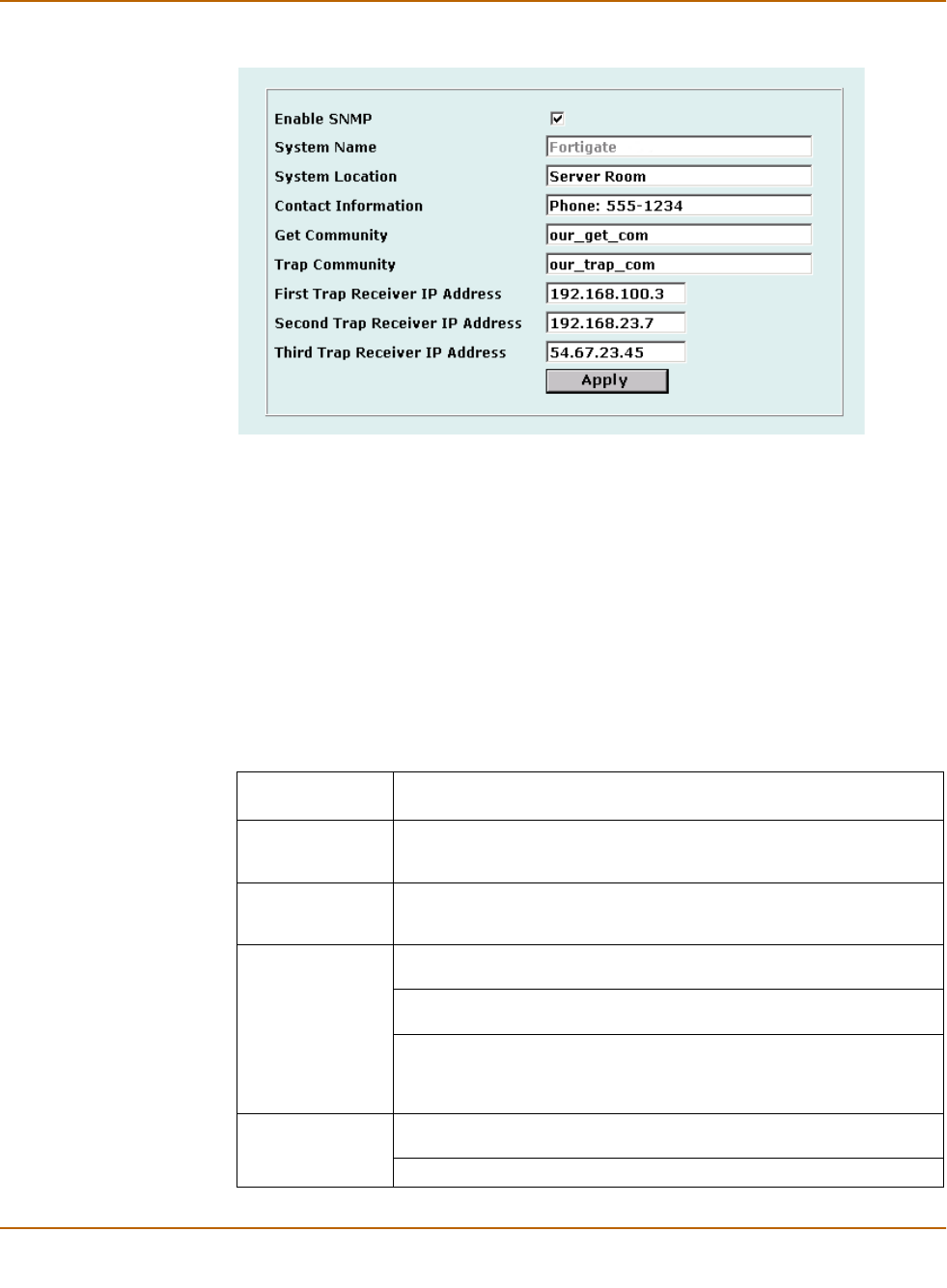
To configure SNMP community settings
1Go to System > Config > SNMP v1/v2c.
2Select the Enable SNMP check box.
3Configure the following SNMP settings:
4Select Apply.
System Name Automatically set to the FortiWiFi host name. To change the System
Name, see “Changing the FortiWiFi host name” on page 74.
System Location Describe the physical location of the FortiWiFi unit. The system location
description can be up to 31 characters long and can contain spaces,
numbers (0-9), uppercase and lowercase letters (A-Z, a-z), and the
special characters - and _. The \ < > [ ] ` $ % & characters are not
allowed.
Contact Information Add the contact information for the person responsible for this FortiWiFi
unit. The contact information can be up to 31 characters long and can
contain spaces, numbers (0-9), uppercase and lowercase letters (A-Z,
a-z), and the special characters - and _. The \ < > [ ] ` $ % & characters
are not allowed.
Get Community Also called read community, get community is a password to identify
SNMP get requests sent to the FortiWiFi unit. When an SNMP manager
sends a get request to the FortiWiFi unit, it must include the correct get
community string.
The default get community string is “public”. Change the default get
community string to keep intruders from using get requests to retrieve
information about your network configuration. The get community string
must be used in your SNMP manager to enable it to access FortiWiFi
SNMP information.
The get community string can be up to 31 characters long and can
contain numbers (0-9), uppercase and lowercase letters (A-Z, a-z), and
the special characters - and _. Spaces and the \ < > [ ] ` $ % &
characters are not allowed.
Trap Community The trap community string functions like a password that is sent with
SNMP traps.
The default trap community string is “public”. Change the trap
community string to the one accepted by your trap receivers.
The trap community string can be up to 31 characters long and can
contain numbers (0-9), uppercase and lowercase letters (A-Z, a-z), and
the special characters - and _. Spaces and the \ < > [ ] ` $ % &
characters are not allowed.
Trap Receiver IP
Addresses
Type the IP addresses of up to three trap receivers on your network that
are configured to receive traps from your FortiWiFi unit. Traps are only
sent to the configured addresses.
150 Fortinet Inc.
Configuring SNMP System configuration
Figure 2: Sample SNMP configuration
FortiWiFi MIBs
The FortiWiFi SNMP agent supports FortiWiFi proprietary MIBs as well as standard
RFC 1213 and RFC 2665 MIBs. The FortiWiFi MIBs are listed in Ta ble 1. You can
obtain these MIB files from Fortinet technical support. To be able to communicate with
the SNMP agent, you must compile all of these MIBs into your SNMP manager.
Your SNMP manager might already include standard and private MIBs in a compiled
database that is ready to use. You must add the Fortinet proprietary MIBs to this
database. If the standard MIBs used by the Fortinet SNMP agent are already
compiled into your SNMP manager you do not have to compile them again.
Table 1: FortiWiFi MIBs
MIB file name or
RFC
Description
fortinet-trap.mib The Fortinet trap MIB is a proprietary MIB that is required for your SNMP
manager to receive traps from the FortiWiFi SNMP agent. For more
information about FortiWiFi traps, see “FortiWiFi traps” on page 151.
fortinet.mib The Fortinet MIB is a proprietary MIB that includes detailed FortiWiFi
system configuration information. Add this MIB to your SNMP manager
to monitor all FortiWiFi configuration settings.
RFC-1213 (MIB II) The FortiWiFi SNMP agent supports MIB II groups with the following
exceptions.
No support for the EGP group from MIB II (RFC 1213, section 3.11 and
6.10).
Protocol statistics returned for MIB II groups (IP/ICMP/TCP/UDP/etc.) do
not accurately capture all FortiWiFi traffic activity. More accurate infor-
mation can be obtained from the information reported by the Fortinet
MIB.
RFC-2665
(Ethernet-like
MIB)
The FortiWiFi SNMP agent supports Ethernet-like MIB information with
the following exception.
No support for the dot3Tests and dot3Errors groups.

System configuration Configuring SNMP
FortiWiFi-60 Installation and Configuration Guide 151
FortiWiFi traps
The FortiWiFi agent can send traps to up to three SNMP trap receivers on your
network that are configured to receive traps from the FortiWiFi unit. For these SNMP
managers to receive traps, you must load and compile the Fortinet trap MIB onto the
SNMP manager.
General FortiWiFi traps
System traps
Table 2: General FortiWiFi traps
Trap message Description
Cold Start The FortiWiFi unit starts or restarts. An administrator enables the
SNMP agent or changes FortiWiFi SNMP settings. This trap is sent
when the agent starts during system startup.
System Down The SNMP agent stops because the FortiWiFi unit shuts down.
Agent Down An administrator disables the SNMP agent.
Agent Up An administrator enables the SNMP agent. This trap is also sent
when the agent starts during system startup.
The <interface_name>
Interface IP is changed
to <new_IP> (Serial
No.:
<FortiWiFi_serial_no>)
The IP address of an interface of a FortiWiFi unit changes. The trap
message includes the name of the interface, the new IP address of
the interface, and the serial number of the FortiWiFi unit. This trap
can be used to track interface IP address changes for interfaces
configured with dynamic IP addresses set using DHCP or PPPoE.
Table 3: FortiWiFi system traps
Trap message Description
interface
<interface_name> is
up.
An interface changes from the up state to the running state, indicating
that the interface has been connected to a network.
When the interface is up it is administratively up but not connected to
a network. When the interface is running it is administratively up and
connected to a network.
interface
<interface_name> is
down.
An interface changes from the running state to the up state, indicating
that the interface has been disconnected from a network.
CPU usage high CPU usage exceeds 90%.
memory low Memory usage exceeds 90%.
disk low On a FortiWiFi unit with a hard drive, hard drive usage exceeds 90%.
<FortiWiFi_serial_no>
<interface_name>
The configuration of an interface of a FortiWiFi unit changes. The trap
message includes the name of the interface and the serial number of
the FortiWiFi unit.
HA switch The primary unit in an HA cluster fails and is replaced with a new pri-
mary unit.

152 Fortinet Inc.
Configuring SNMP System configuration
VPN traps
NIDS traps
Antivirus traps
Logging traps
Fortinet MIB fields
The Fortinet MIB contains fields for configuration settings and current status
information for all parts of the FortiWiFi product. This section lists the names of the
high-level MIB fields and describes the configuration and status information available
for each one. You can view more details about the information available from all
Fortinet MIB fields by compiling the fortinet.mib file into your SNMP manager and
browsing the Fortinet MIB fields.
Table 4: FortiWiFi VPN traps
Trap message Description
VPN tunnel is up An IPSec VPN tunnel starts up and begins processing network traf-
fic.
VPN tunnel down An IPSec VPN tunnel shuts down.
Table 5: FortiWiFi NIDS traps
Trap message Description
Flood attack happened. NIDS attack prevention detects and provides protection from a
syn flood attack.
Port scan attack hap-
pened.
NIDS attack prevention detects and provides protection from a
port scan attack.
Table 6: FortiWiFi antivirus traps
Trap message Description
virus detected The FortiWiFi unit detects a virus and removes the infected file from an
HTTP or FTP download or from an email message.
Table 7: FortiWiFi logging traps
Trap message Description
log full On a FortiWiFi unit with a hard drive, hard drive usage exceeds 90%. On a
FortiWiFi unit without a hard drive, log to memory usage has exceeds 90%.

System configuration Configuring SNMP
FortiWiFi-60 Installation and Configuration Guide 153
System configuration and status
Firewall configuration
Users and authentication configuration
Table 8: System MIB fields
MIB field Description
fnSysStatus FortiWiFi system configuration including operation mode, firmware version,
virus definition version, attack definition version, and serial number. Status
monitor information including current CPU usage, CPU idle status, CPU
interrupts, memory usage, system up time, the number of active communi-
cation sessions, as well as descriptive information for each active communi-
cation session.
fnSysUpdate FortiWiFi system update configuration including connection status to the
FDN, push update status, periodic update status, and current virus and
attack definitions versions.
fnSysNetwork FortiWiFi system network configuration including the interface, VLAN, rout-
ing, DHCP, zone, and DNS configuration.
fnSysConfig FortiWiFi system configuration including time, options, administrative users,
and HA configuration.
fnSysSnmp FortiWiFi SNMP configuration.
Table 9: Firewall MIB fields
MIB field Description
fnFirewallPolicy FortiWiFi firewall policy list including complete configuration infor-
mation for each policy.
fnFirewallAddress FortiWiFi firewall address and address group list.
fnFirewallService FortiWiFi firewall service and service group list.
fnFirewallSchedule FortiWiFi firewall schedule list.
fnFirewallVirtualIP FortiWiFi firewall virtual IP list.
fnFirewallIpPool FortiWiFi firewall IP pool list.
fnFirewallIPMACBinding FortiWiFi firewall IP/MAC binding configuration.
fnFirewallContProfiles FortiWiFi firewall content profile list.
Table 10: User and authentication MIB fields
FnUserLocalTable Local user list.
FnUserRadiusSrvTable RADIUS server list.
FnUserGrpTable User group list.

154 Fortinet Inc.
Configuring SNMP System configuration
VPN configuration and status
NIDS configuration
Antivirus configuration
Web filter configuration
Logging and reporting configuration
Table 11: VPN MIB fields
fnVpnIpsec IPSec VPN configuration including the Phase 1 list, Phase 2 list, manual key
list, and VPN concentrator list. Status and timeout for each VPN tunnel
(Phase 2) and the dialup monitor list showing dialup tunnel status.
fnVpnPPTP PPTP VPN configuration.
fnVpnL2TP L2TP VPN configuration.
fnVpnCert IPSec VPN with certificates configuration.
Table 12: NIDS MIB fields
fnNidsDetection NIDS detection configuration.
fnNidsPrevention NIDS prevention configuration.
fnNidsResponse NIDS response configuration.
Table 13: Antivirus MIB fields
fnAvFileBlock Antivirus file blocking configuration.
fnAvQuarantine Antivirus quarantine configuration.
fnAVConfig Antivirus configuration including the current virus definition virus list.
Table 14: Web filter MIB fields
fnWebFiltercfgMsgTable Web filter content block list and configuration.
fnWebFilterUrlBlk Web filter URL block list.
fnWebFilterScripts Web filter script blocking configuration.
fnWebFilterExemptUrl Web filter exempt URL list.
Table 15: Logging and reporting MIB fields
fnLoglogSetting Log setting configuration.
fnLoglog Log setting traffic filter configuration.
fnLogAlertEmail Alert email configuration.
System configuration Replacement messages
FortiWiFi-60 Installation and Configuration Guide 155
Replacement messages
Replacement messages are added to content passing through the firewall to replace:
• Files or other content removed from POP3 and IMAP email messages by the
antivirus system,
• Files or other content removed from HTTP downloads by the antivirus system or
web filtering,
• Files removed from FTP downloads by the antivirus system.
You can edit the content of replacement messages.
You can also edit the content added to alert email messages to control the information
that appears in alert emails for virus incidents, NIDS events, critical system events,
and disk full events.
This section describes:
•Customizing replacement messages
•Customizing alert emails
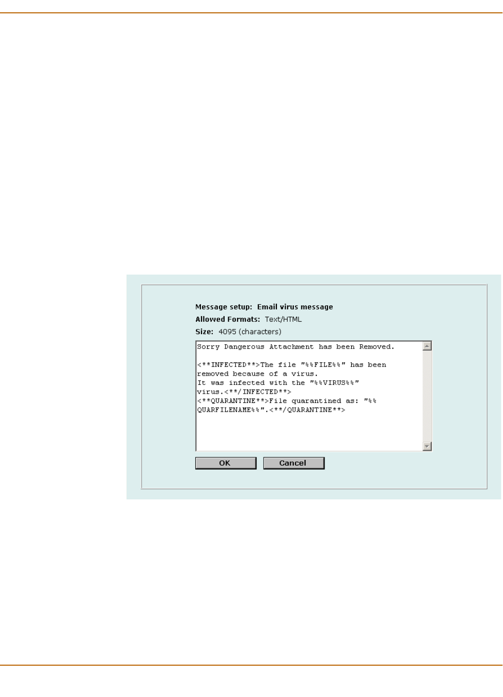
Figure 3: Sample replacement message
Customizing replacement messages
Each of the replacement messages in the replacement message list is created by
combining replacement message sections. You can use these sections as building
blocks to create your own replacement messages.
You can edit any of the replacement messages in the replacement message list and
add and edit the replacement message sections as required.
To customize a replacement message
1Go to System > Config > Replacement Messages.
156 Fortinet Inc.
Replacement messages System configuration
2For the replacement message that you want to customize, select Modify .
3In the Message setup dialog box, edit the content of the message.
Tab le 1 6 lists the replacement message sections that can be added to replacement
messages and describes the tags that can appear in each section. In addition to the
allowed tags you can add text. For mail and HTTP messages you can also add HTML
code.
4Select OK to save the changes.
Customizing alert emails
Customize alert emails to control the content displayed in alert email messages sent
to system administrators.
To customize alert emails
1Go to System > Config > Replacement Messages.
2For the alert email message that you want to customize, select Modify .
3In the Message setup dialog box, edit the text of the message.
Tab le 1 7 lists the replacement message sections that can be added to alert email
messages and describes the tags that can appear in each section. In addition to the
allowed tags you can add text and HTML code.
4Select OK to save the changes.
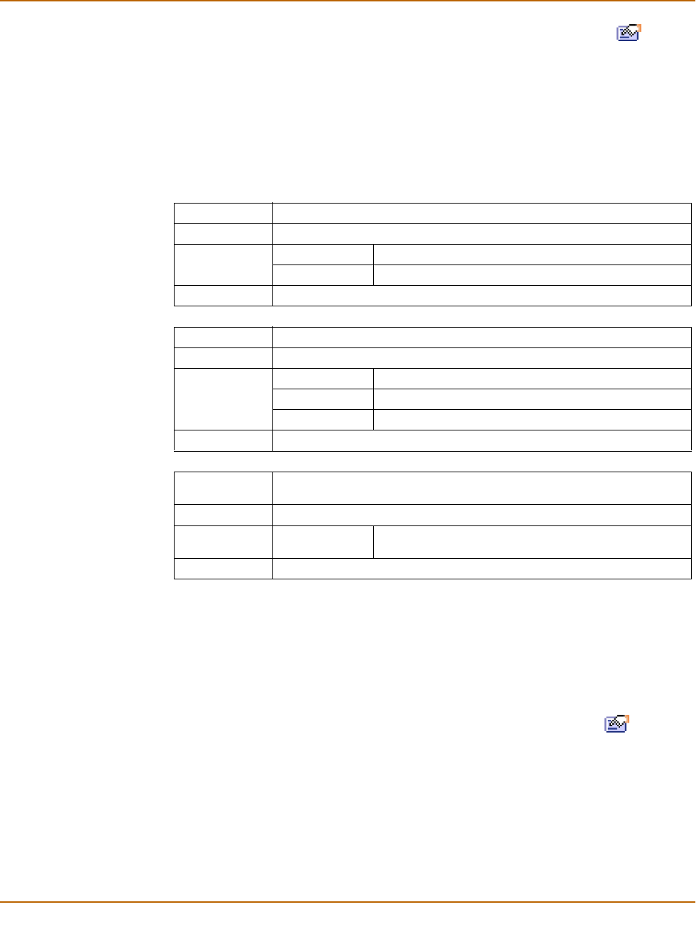
Table 16: Replacement message sections
File blocking Used for file blocking (all services).
Section Start <**BLOCKED**>
Allowed Tags %%FILE%% The name of the file that was blocked.
%%URL%% The URL of the blocked web page.
Section End <**/BLOCKED**>
Scanning Used for virus scanning (all services).
Section Start <**INFECTED**>
Allowed Tags %%FILE%% The name of the file that was infected.
%%VIRUS%% The name of the virus infecting the file.
%%URL%% The URL of the blocked web page or file.
Section End <**/INFECTED**>
Quarantine Used when quarantine is enabled (permitted for all scan services and block
services for email only).
Section Start <**QUARANTINE**>
Allowed Tag %%QUARFILE
NAME%%
The name of the file that was quarantined.
Section End <**/QUARANTINE**>

System configuration Replacement messages
FortiWiFi-60 Installation and Configuration Guide 157
Table 17: Alert email message sections
NIDS event Used for NIDS event alert email messages
Section Start <**NIDS_EVENT**>
Allowed Tags %%NIDS_EVENT%% The NIDS attack message.
Section End <**/NIDS_EVENT**>
Virus alert Used for virus alert email messages
Section Start <**VIRUS_ALERT**>
Allowed Tags %%VIRUS%% The name of the virus.
%%PROTOCOL%% The service for which the virus was detected.
%%SOURCE_IP%% The IP address from which the virus was received.
For email this is the IP address of the email server
that sent the email containing the virus. For HTTP
this is the IP address of web page that sent the
virus.
%%DEST_IP%% The IP address of the computer that would have
received the virus. For POP3 this is the IP address
of the user’s computer that attempted to download
the email containing the virus.
%%EMAIL_FROM%% The email address of the sender of the message in
which the virus was found.
%%EMAIL_TO%% The email address of the intended receiver of the
message in which the virus was found.
Section End <**/VIRUS_ALERT**>
Block alert Used for file block alert email messages
Section Start <**BLOCK_ALERT**>
Allowed Tags %%FILE%% The name of the file that was blocked.
%%PROTOCOL%% The service for which the file was blocked.
%%SOURCE_IP%% The IP address from which the block file was
received. For email this is the IP address of the
email server that sent the email containing the
blocked file. For HTTP this is the IP address of
web page that sent the blocked file.
%%DEST_IP%% The IP address of the computer that would have
received the blocked file. For email this is the IP
address of the user’s computer that attempted to
download the message from which the file ware
removed.
%%EMAIL_FROM%% The email address of the sender of the message
from which the file was removed.
%%EMAIL_TO%% The email address of the intended receiver of the
message from which the file was removed.
Section End <**/BLOCK_ALERT**>

158 Fortinet Inc.
Replacement messages System configuration
Critical event Used for critical firewall event alert emails.
Section Start <**CRITICAL_EVENT**>
Allowed Tags %%CRITICAL_EVENT
%%
The firewall critical event message
Section End <**/CRITICAL_EVENT**>

FortiWiFi-60 Installation and Configuration Guide Version 2.50
FortiWiFi-60 Installation and Configuration Guide 159
Firewall configuration
Firewall policies control all traffic passing through the FortiWiFi unit. Firewall policies
are instructions that the FortiWiFi unit uses to decide what to do with a connection
request. When the firewall receives a connection request in the form of a packet, it
analyzes the packet to extract its source address, destination address, and service
(port number).
For the packet to be connected through the FortiWiFi unit, a firewall policy must be in
place that matches the source address, destination address, and service of the
packet. The policy directs the firewall action on the packet. The action can be to allow
the connection, deny the connection, require authentication before the connection is
allowed, or process the packet as an IPSec VPN packet. You can also add schedules
to policies so that the firewall can process connections differently depending on the
time of day or the day of the week, month, or year.
Each policy can be individually configured to route connections or apply network
address translation (NAT) to translate source and destination IP addresses and ports.
You can add IP pools to use dynamic NAT when the firewall translates source
addresses. You can use policies to configure port address translation (PAT) through
the FortiWiFi.
You can add content profiles to policies to apply antivirus protection, web filtering, and
email filtering to web, file transfer, and email services. You can create content profiles
that perform one or any combination of the following actions:
• Apply antivirus protection to HTTP, FTP, SMTP, IMAP, or POP3 services.
• Apply web filtering to HTTP services.
• Apply email filtering to IMAP and POP3 services.
You can also add logging to a firewall policy so that the FortiWiFi unit logs all
connections that use this policy.
160 Fortinet Inc.
Default firewall configuration Firewall configuration
This chapter describes:
•Default firewall configuration
•Adding firewall policies
•Configuring policy lists
•Addresses
•Services
•Schedules
•Virtual IPs
•IP pools
•IP/MAC binding
•Content profiles
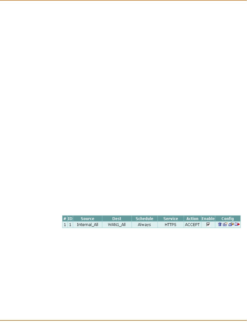
Default firewall configuration
By default, the users on your internal network can connect through the FortiWiFi unit
to the Internet through the WAN1 and WAN2 interfaces. Users on the wireless
network can also connect to the internet through the WAN1 and WAN2 interfaces. The
firewall blocks all other connections. The firewall is configured with default policies
that matches any connection request received from the internal network and instructs
the firewall to forward the connection through the WAN1 or WAN2 interfaces to the
Internet. Other default policies match any connection from the wireless network and
instructs the firewall to forward the connection through the WAN1 or WAN2 interfaces.
The destination interface selected depends on the destination of the packet, as
determined by routing.
The default policy also applies virus scanning to all HTTP, FTP, SMTP, POP3, and
IMAP traffic matched by the policy. The policy applies virus scanning because the
Antivirus & Web Filter option is selected and the Content profile is set to Scan. For
more information about content profiles, see “Content profiles” on page 189.
Figure 4: Default firewall policy
•Interfaces
•Addresses
•Services
•Schedules
•Content profiles

Firewall configuration Default firewall configuration
FortiWiFi-60 Installation and Configuration Guide 161
Interfaces
Add policies to control connections between FortiWiFi interfaces and between the
networks connected to these interfaces. By default, you can add policies for
connections that include the internal, WAN1, and DMZ interfaces. If you want to add
policies that include the WAN2 and WLAN interface or the modem interface, you must
add firewall addresses for these interfaces. For information about firewall addresses,
see “Addresses” on page 169.
Addresses
To add policies between interfaces, the firewall configuration must contain addresses
for each interface. By default the firewall configuration includes the following firewall
addresses.
• Internal_All, added to the internal interface, this address matches all addresses on
the internal network.
• WAN1_All, added to the WAN1 interface, this address matches all addresses on
the WAN1 network.
• WAN2_All, added to the WAN2 interface, this address matches all addresses on
the WAN2 network.
• WLAN_All, added to the WLAN interface, this address matches all addresses on
the wireless (WLAN) network.
• DMZ_All, added to the DMZ interface, this address matches all addresses on the
DMZ network.
The firewall uses these addresses to match the source and destination addresses of
packets received by the firewall. The default Internal->WAN1 policy matches all
connections from the internal network because it includes the Internal_All address.
The default policy also matches all connections to the WAN1 network because it
includes the WAN1_All address.
The other default policies function in the same manner.
You can add more addresses to each interface to improve the control you have over
connections through the firewall. For more information about addresses, see
“Addresses” on page 169.
You can also add firewall policies that perform network address translation (NAT). To
use NAT to translate destination addresses, you must add virtual IPs. Virtual IPs map
addresses on one network to a translated address on another network. For more
information about Virtual IPs, see “Virtual IPs” on page 180.
Services
Policies can control connections based on the service or destination port number of
packets. The default policy accepts connections using any service or destination port
number. The firewall is configured with over 40 predefined services. You can add
these services to a policy for more control over the services that can be used by
connections through the firewall. You can also add user-defined services. For more
information about services, see “Services” on page 172.

162 Fortinet Inc.
Adding firewall policies Firewall configuration
Schedules
Policies can control connections based on the time of day or day of the week when the
firewall receives the connection. The default policy accepts connections at any time.
The firewall is configured with one schedule that accepts connections at any time. You
can add more schedules to control when policies are active. For more information
about schedules, see “Schedules” on page 177.
Content profiles
Add content profiles to policies to apply antivirus protection, web filtering, and email
filtering to web, file transfer, and email services. The FortiWiFi unit includes the
following default content profiles:
• Strict—to apply maximum content protection to HTTP, FTP, IMAP, POP3, and
SMTP content traffic.
• Scan—to apply antivirus scanning to HTTP, FTP, IMAP, POP3, and SMTP content
traffic.
• Web—to apply antivirus scanning and Web content blocking to HTTP content
traffic.
• Unfiltered—to allow oversized files to pass through the FortiWiFi unit without
scanned for viruses.
The default policy includes the scan content profile.
For more information about content profiles, see “Content profiles” on page 189.
Adding firewall policies
Add Firewall policies to control connections and traffic between FortiWiFi interfaces.
To add a firewall policy
1Go to Firewall > Policy.
2Select the policy list to which you want to add the policy.
3Select New to add a new policy.
You can also select Insert Policy before on a policy in the list to add the new
policy above a specific policy.
4Configure the policy:
For information about configuring the policy, see “Firewall policy options” on page 163.
5Select OK to add the policy.
6Arrange policies in the policy list so that they have the results that you expect.
For information about arranging policies in a policy list, see “Configuring policy lists”
on page 167.
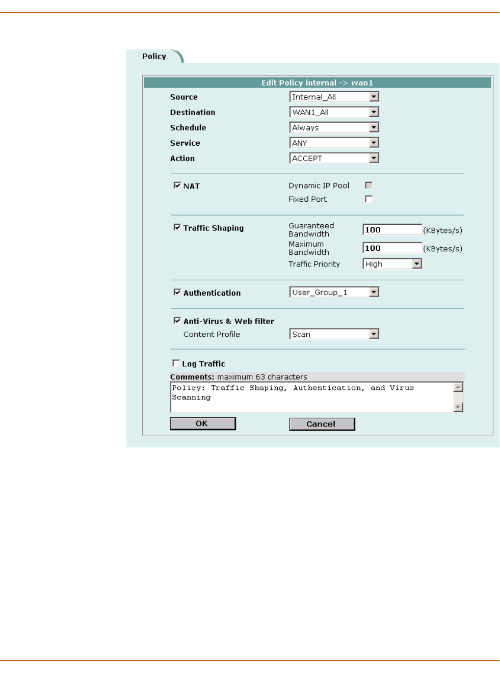
Firewall configuration Adding firewall policies
FortiWiFi-60 Installation and Configuration Guide 163
Figure 5: Adding a NAT/Route policy
Firewall policy options
This section describes the options that you can add to firewall policies.
Source
Select an address or address group that matches the source address of the packet.
Before you can add this address to a policy, you must add it to the source interface.
For information about adding an address, see “Addresses” on page 169.
Destination
Select an address or address group that matches the destination address of the
packet. Before you can add this address to a policy, you must add it to the destination
interface. For information about adding an address, see “Addresses” on page 169.

164 Fortinet Inc.
Adding firewall policies Firewall configuration
For NAT/Route mode policies where the address on the destination network is hidden
from the source network using NAT, the destination can also be a virtual IP that maps
the destination address of the packet to a hidden destination address. See “Virtual
IPs” on page 180.
Schedule
Select a schedule that controls when the policy is available to be matched with
connections. See “Schedules” on page 177.
Service
Select a service that matches the service (port number) of the packet. You can select
from a wide range of predefined services or add custom services and service groups.
See “Services” on page 172.
Action
Select how you want the firewall to respond when the policy matches a connection
attempt.
NAT
Configure the policy for NAT. NAT translates the source address and the source port
of packets accepted by the policy. If you select NAT, you can also select Dynamic IP
Pool and Fixed Port. NAT is not available in Transparent mode.
VPN Tunnel
Select a VPN tunnel for an ENCRYPT policy. You can select an AutoIKE key or
Manual Key tunnel. VPN Tunnel is not available in Transparent mode.
ACCEPT Accept the connection. If you select ACCEPT, you can also configure NAT
and Authentication for the policy.
DENY Deny the connection. The only other policy option that you can configure is
Log Traffic, to log the connections denied by this policy.
ENCRYPT Make this policy an IPSec VPN policy. If you select ENCRYPT, you can
select an AutoIKE Key or Manual Key VPN tunnel for the policy and
configure other IPSec settings. You cannot add authentication to an
ENCRYPT policy. ENCRYPT is not available in Transparent mode. See
“Configuring encrypt policies” on page 215.
Dynamic IP
Pool
Select Dynamic IP Pool to translate the source address to an address
randomly selected from an IP pool. The IP pool must be added to the
destination interface of the policy.
You cannot select Dynamic IP Pool if the destination interface is configured
using DHCP or PPPoE.
For information about adding IP pools, see “IP pools” on page 184.
Fixed Port Select Fixed Port to prevent NAT from translating the source port. Some
applications do not function correctly if the source port is changed. If you
select Fixed Port, you must also select Dynamic IP Pool and add a dynamic
IP pool address range to the destination interface of the policy. If you do not
select Dynamic IP Pool, a policy with Fixed Port selected can only allow one
connection at a time for this port or service.

Firewall configuration Adding firewall policies
FortiWiFi-60 Installation and Configuration Guide 165
Traffic Shaping
Traffic Shaping controls the bandwidth available to and sets the priority of the traffic
processed by the policy. Traffic Shaping makes it possible to control which policies
have the highest priority when large amounts of data are moving through the FortiWiFi
device. For example, the policy for the corporate web server might be given higher
priority than the policies for most employees’ computers. An employee who needs
unusually high-speed Internet access could have a special outgoing policy set up with
higher bandwidth.
If you set both guaranteed bandwidth and maximum bandwidth to 0 the policy does
not allow any traffic.
Authentication
Select Authentication and select a user group to require users to enter a user name
and password before the firewall accepts the connection. Select the user group to
control the users that can authenticate with this policy. For information about adding
and configuring user groups, see “Configuring user groups” on page 199. You must
add user groups before you can select Authentication.
You can select Authentication for any service. Users can authenticate with the firewall
using HTTP, Telnet, or FTP. For users to be able to authenticate you must add an
HTTP, Telnet, or FTP policy that is configured for authentication. When users attempt
to connect through the firewall using this policy they are prompted to enter a firewall
username and password.
If you want users to authenticate to use other services (for example POP3 or IMAP)
you can create a service group that includes the services for which you want to
require authentication, as well as HTTP, Telnet, and FTP. Then users could
authenticate with the policy using HTTP, Telnet, or FTP before using the other service.
Allow inbound Select Allow inbound so that users behind the remote VPN gateway can
connect to the source address.
Allow outbound Select Allow outbound so that users can connect to the destination address
behind the remote VPN gateway.
Inbound NAT Select Inbound NAT to translate the source address of incoming packets to
the FortiWiFi internal IP address.
Outbound NAT Select Outbound NAT to translate the source address of outgoing packets to
the FortiWiFi external IP address.
Guaranteed
Bandwidth
You can use traffic shaping to guarantee the amount of bandwidth available
through the firewall for a policy. Guarantee bandwidth (in Kbytes) to make
sure that there is enough bandwidth available for a high-priority service.
Maximum
Bandwidth
You can also use traffic shaping to limit the amount of bandwidth available
through the firewall for a policy. Limit bandwidth to keep less important
services from using bandwidth needed for more important services.
Traffic Priority Select High, Medium, or Low. Select Traffic Priority so that the FortiWiFi unit
manages the relative priorities of different types of traffic. For example, a
policy for connecting to a secure web server needed to support e-commerce
traffic should be assigned a high traffic priority. Less important services
should be assigned a low priority. The firewall provides bandwidth to low-
priority connections only when bandwidth is not needed for high-priority
connections.
166 Fortinet Inc.
Adding firewall policies Firewall configuration
In most cases you should make sure that users can use DNS through the firewall
without authentication. If DNS is not available users cannot connect to a web, FTP, or
Telnet server using a domain name.
Anti-Virus & Web filter
Enable antivirus protection and web filter content filtering for traffic controlled by this
policy. You can select Anti-Virus & Web filter if Service is set to ANY, HTTP, SMTP,
POP3, IMAP, or FTP or to a service group that includes the HTTP, SMTP, POP3,
IMAP, or FTP services.
Select a content profile to configure how antivirus protection and content filtering is
applied to the policy. For information about selecting a content profile, see “Content
profiles” on page 189.
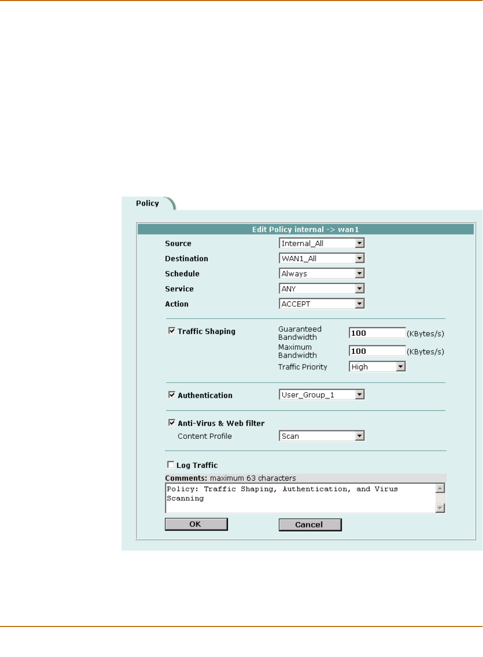
Figure 6: Adding a Transparent mode policy

Firewall configuration Configuring policy lists
FortiWiFi-60 Installation and Configuration Guide 167
Log Traffic
Select Log Traffic to write messages to the traffic log whenever the policy processes a
connection. For information about logging, see “Logging and reporting” on page 273.
Comments
You can add a description or other information about the policy. The comment can be
up to 63 characters long, including spaces.
Configuring policy lists
The firewall matches policies by searching for a match starting at the top of the policy
list and moving down until it finds the first match. You must arrange policies in the
policy list from more specific to more general.
For example, the default policy is a very general policy because it matches all
connection attempts. When you create exceptions to that policy, you must add them to
the policy list above the default policy. No policy below the default policy will ever be
matched.
This section describes:
•Policy matching in detail
•Changing the order of policies in a policy list
•Enabling and disabling policies
Policy matching in detail
When the FortiWiFi unit receives a connection attempt at an interface, it must select a
policy list to search through for a policy that matches the connection attempt. The
FortiWiFi unit chooses the policy list based on the source and destination addresses
of the connection attempt.
The FortiWiFi unit then starts at the top of the selected policy list and searches down
the list for the first policy that matches the connection attempt source and destination
addresses, service port, and time and date at which the connection attempt was
received. The first policy that matches is applied to the connection attempt. If no policy
matches, the connection is dropped.
The default policy accepts all connection attempts from the internal network to the
Internet. From the internal network, users can browse the web, use POP3 to get
email, use FTP to download files through the firewall, and so on. If the default policy is
at the top of the Internal->WAN1 policy list, the firewall allows all connections from the
internal network through the WAN1 interface to the Internet because all connections
match the default policy. If more specific policies are added to the list below the default
policy, they are never matched.

168 Fortinet Inc.
Configuring policy lists Firewall configuration
A policy that is an exception to the default policy, for example, a policy to block FTP
connections, must be placed above the default policy in the Internal->WAN1 policy
list. In this example, all FTP connection attempts from the internal network would then
match the FTP policy and be blocked. Connection attempts for all other kinds of
services would not match with the FTP policy but they would match with the default
policy. Therefore, the firewall would still accept all other connections from the internal
network.
Changing the order of policies in a policy list
To change the order of a policy in a policy list
1Go to Firewall > Policy.
2Select the policy list that you want to change the order of.
3Choose the policy that you want to move and select Move To to change its order
in the policy list.
4Type a number in the Move to field to specify where in the policy list to move the policy
and select OK.
Enabling and disabling policies
You can enable and disable policies in the policy list to control whether the policy is
active or not. The FortiWiFi unit matches enabled policies but does not match
disabled policies.
Disabling policies
Disable a policy to temporarily prevent the firewall from selecting the policy. Disabling
a policy does not stop active communications sessions that have been allowed by the
policy. For information about stopping active communication sessions, see “System
status” on page 87.
To disable a policy
1Go to Firewall > Policy.
2Select the policy list that contains the policy that you want to disable.
3Clear the check box of the policy to disable it.
Enabling policies
Enable a policy that has been disabled so that the firewall can match connections with
the policy.
To enable a policy
1Go to Firewall > Policy.
2Select the policy list that contains the policy that you want to enable.
3Select the check box of the policy to enable it.
Note: Policies that require authentication must be added to the policy list above matching
policies that do not; otherwise, the policy that does not require authentication is selected first.

Firewall configuration Addresses
FortiWiFi-60 Installation and Configuration Guide 169
Addresses
All policies require source and destination addresses. To add addresses to a policy
between two interfaces, you must first add addresses to the address list for each
interface.
You can add, edit, and delete all firewall addresses as required. You can also organize
related addresses into address groups to simplify policy creation.
A firewall address consists of an IP address and a netmask. This information can
represent:
• The address of a subnet (for example, for a class C subnet,
IP address: 192.168.20.0 and Netmask: 255.255.255.0).
• A single IP address (for example, IP Address: 192.168.20.1 and
Netmask: 255.255.255.255)
• All possible IP addresses (represented by IP Address: 0.0.0.0 and Netmask:
0.0.0.0)
This section describes:
•Adding addresses
•Editing addresses
•Deleting addresses
•Organizing addresses into address groups
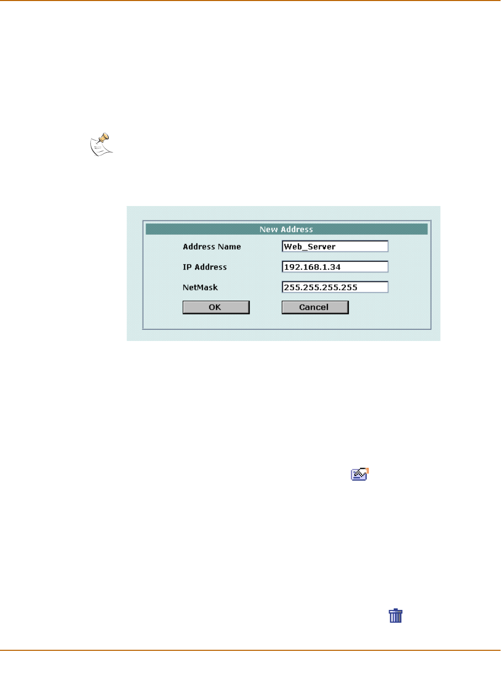
Adding addresses
To add an address
1Go to Firewall > Address.
2Select the interface that you want to add the address to.
3Select New to add a new address.
4Enter an Address Name to identify the address.
The name can contain numbers (0-9), uppercase and lowercase letters (A-Z, a-z), and
the special characters - and _. Spaces and other special characters are not allowed.
5Enter the IP Address.
The IP address can be:
• The IP address of a single computer (for example, 192.45.46.45).
• The IP address of a subnetwork (for example, 192.168.1.0 for a class C subnet).
• 0.0.0.0 to represent all possible IP addresses
Note: IP address: 0.0.0.0 and Netmask: 255.255.255.255 is not a valid firewall address.
170 Fortinet Inc.
Addresses Firewall configuration
6Enter the Netmask.
The netmask corresponds to the type of address that you are adding. For example:
• The netmask for the IP address of a single computer should be 255.255.255.255.
• The netmask for a class A subnet should be 255.0.0.0.
• The netmask for a class B subnet should be 255.255.0.0.
• The netmask for a class C subnet should be 255.255.255.0.
• The netmask for all addresses should be 0.0.0.0
7Select OK to add the address.
Figure 7: Adding an internal address
Editing addresses
Edit an address to change its IP address and netmask. You cannot edit the address
name. To change the address name, you must delete the address entry and then add
the address again with a new name.
To edit an address
1Go to Firewall > Address.
2Select the interface list containing the address that you want to edit.
3Choose an address to edit and select Edit Address .
4Make the required changes and select OK to save the changes.
Deleting addresses
Deleting an address removes it from an address list. To delete an address that has
been added to a policy, you must first remove the address from the policy.
To delete an address
1Go to Firewall > Address.
2Select the interface list containing the address that you want to delete.
You can delete any address that has a Delete Address icon .
Note: To add an address to represent any address on a network set the IP Address to 0.0.0.0
and the Netmask to 0.0.0.0
Firewall configuration Addresses
FortiWiFi-60 Installation and Configuration Guide 171
3Choose an address to delete and select Delete .
4Select OK to delete the address.
Organizing addresses into address groups
You can organize related addresses into address groups to make it easier to add
policies. For example, if you add three addresses and then add them to an address
group, you only have to add one policy using the address group rather than a separate
policy for each address.
You can add address groups to any interface. The address group can only contain
addresses from that interface. Address groups are available in interface source or
destination address lists.
Address groups cannot have the same names as individual addresses. If an address
group is included in a policy, it cannot be deleted unless it is first removed from the
policy.
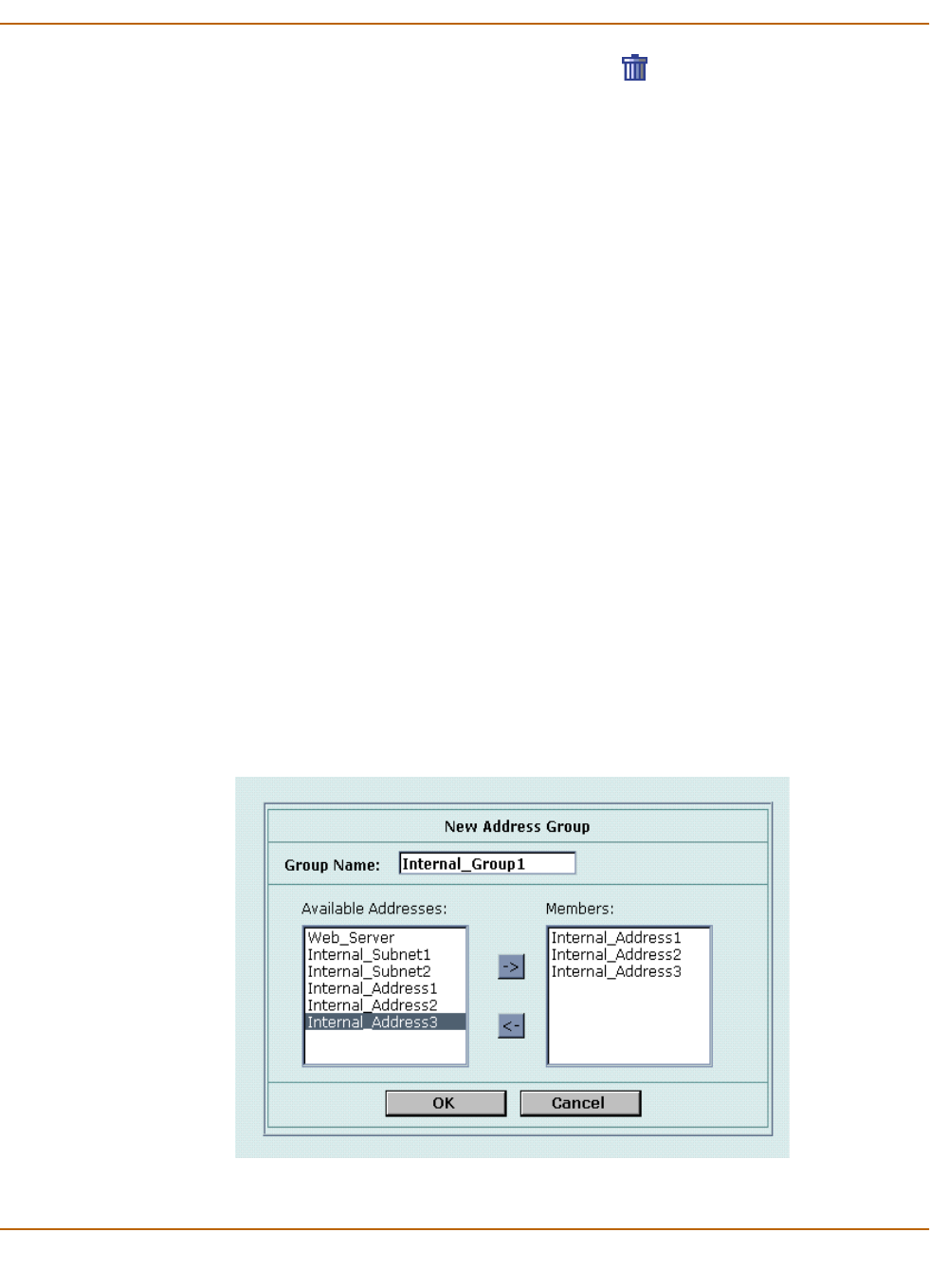
To organize addresses into an address group
1Go to Firewall > Address > Group.
2Select the interface that you want to add the address group to.
3Enter a Group Name to identify the address group.
The name can contain numbers (0-9), uppercase and lowercase letters (A-Z, a-z), and
the special characters - and _. Other special characters and spaces are not allowed.
4To add addresses to the address group, select an address from the Available
Addresses list and select the right arrow to add it to the Members list.
5To remove addresses from the address group, select an address from the Members
list and select the left arrow to remove it from the group.
6Select OK to add the address group.
Figure 8: Adding an internal address group

172 Fortinet Inc.
Services Firewall configuration
Services
Use services to determine the types of communication accepted or denied by the
firewall. You can add any of the predefined services to a policy. You can also create
custom services and add services to service groups.
This section describes:
•Predefined services
•Adding custom TCP and UDP services
•Adding custom ICMP services
•Adding custom IP services
•Grouping services
Predefined services
The FortiWiFi predefined firewall services are listed in Ta bl e 18. You can add these
services to any policy.
Table 18: FortiWiFi predefined services
Service name Description Protocol Port
ANY Match connections on any port. A connection
that uses any of the predefined services is
allowed through the firewall.
all all
GRE Generic Routing Encapsulation. A protocol
that allows an arbitrary network protocol to be
transmitted over any other arbitrary network
protocol, by encapsulating the packets of the
protocol within GRE packets.
47
AH Authentication Header. AH provides source
host authentication and data integrity, but not
secrecy. This protocol is used for
authentication by IPSec remote gateways set
to aggressive mode.
51
ESP Encapsulating Security Payload. This service
is used by manual key and AutoIKE VPN
tunnels for communicating encrypted data.
AutoIKE key VPN tunnels use ESP after
establishing the tunnel using IKE.
50
AOL AOL instant messenger protocol. tcp 5190-5194
BGP Border Gateway Protocol routing protocol.
BGP is an interior/exterior routing protocol.
tcp 179
DHCP-Relay Dynamic Host Configuration Protocol (DHCP)
allocates network addresses and delivers
configuration parameters from DHCP servers
to hosts.
udp 67
DNS Domain name service for translating domain
names into IP addresses.
tcp 53
udp 53
FINGER A network service that provides information
about users.
tcp 79
FTP FTP service for transferring files. tcp 21

Firewall configuration Services
FortiWiFi-60 Installation and Configuration Guide 173
GOPHER Gopher communication service. Gopher
organizes and displays Internet server
contents as a hierarchically structured list of
files.
tcp 70
H323 H.323 multimedia protocol. H.323 is a
standard approved by the International
Telecommunication Union (ITU) that defines
how audiovisual conferencing data is
transmitted across networks.
tcp 1720, 1503
HTTP HTTP is the protocol used by the word wide
web for transferring data for web pages.
tcp 80
HTTPS HTTP with secure socket layer (SSL) service
for secure communication with web servers.
tcp 443
IKE IKE is the protocol to obtain authenticated
keying material for use with ISAKMP for
IPSEC.
udp 500
IMAP Internet Message Access Protocol is a
protocol used for retrieving email messages.
tcp 143
Internet-Locator-
Service
Internet Locator Service includes LDAP, User
Locator Service, and LDAP over TLS/SSL.
tcp 389
IRC Internet Relay Chat allows people connected
to the Internet to join live discussions.
tcp 6660-6669
L2TP L2TP is a PPP-based tunnel protocol for
remote access.
tcp 1701
LDAP Lightweight Directory Access Protocol is a set
of protocols used to access information
directories.
tcp 389
NetMeeting NetMeeting allows users to teleconference
using the Internet as the transmission
medium.
tcp 1720
NFS Network File System allows network users to
access shared files stored on computers of
different types.
tcp 111, 2049
NNTP Network News Transport Protocol is a
protocol used to post, distribute, and retrieve
USENET messages.
tcp 119
NTP Network time protocol for synchronizing a
computer’s time with a time server.
tcp 123
OSPF Open Shortest Path First (OSPF) routing
protocol. OSPF is a common link state
routing protocol.
89
PC-Anywhere PC-Anywhere is a remote control and file
transfer protocol.
udp 5632
PING ICMP echo request/reply for testing
connections to other devices.
icmp 8
TIMESTAMP ICMP timestamp request messages. icmp 13
INFO_REQUEST ICMP information request messages. icmp 15
INFO_ADDRESS ICMP address mask request messages. icmp 17
POP3 Post office protocol email protocol for
downloading email from a POP3 server.
tcp 110
Table 18: FortiWiFi predefined services (Continued)
Service name Description Protocol Port

174 Fortinet Inc.
Services Firewall configuration
Adding custom TCP and UDP services
Add a custom TCP or UDP service if you need to create a policy for a service that is
not in the predefined service list.
To add a custom TCP or UDP service
1Go to Firewall > Service > Custom.
2Select TCP/UDP from the Protocol list.
PPTP Point-to-Point Tunneling Protocol is a
protocol that allows corporations to extend
their own corporate network through private
tunnels over the public Internet.
tcp 1723
QUAKE For connections used by the popular Quake
multi-player computer game.
udp 26000,
27000,
27910,
27960
RAUDIO For streaming real audio multimedia traffic. udp 7070
RLOGIN Rlogin service for remotely logging into a
server.
tcp 513
RIP Routing Information Protocol is a common
distance vector routing protocol.
udp 520
SMTP For sending mail between email servers on
the Internet.
tcp 25
SNMP Simple Network Management Protocol is a
set of protocols for managing complex
networks
tcp 161-162
udp 161-162
SSH SSH service for secure connections to
computers for remote management.
tcp 22
udp 22
SYSLOG Syslog service for remote logging. udp 514
TALK A protocol supporting conversations between
two or more users.
udp 517-518
TCP All TCP ports. tcp 0-65535
TELNET Telnet service for connecting to a remote
computer to run commands.
tcp 23
TFTP Trivial file transfer protocol, a simple file
transfer protocol similar to FTP but with no
security features.
udp 69
UDP All UDP ports. udp 0-65535
UUCP Unix to Unix copy utility, a simple file copying
protocol.
udp 540
VDOLIVE For VDO Live streaming multimedia traffic. tcp 7000-7010
WAIS Wide Area Information Server. An Internet
search protocol.
tcp 210
WINFRAME For WinFrame communications between
computers running Windows NT.
tcp 1494
X-WINDOWS For remote communications between an
X-Window server and X-Window clients.
tcp 6000-6063
Table 18: FortiWiFi predefined services (Continued)
Service name Description Protocol Port

Firewall configuration Services
FortiWiFi-60 Installation and Configuration Guide 175
3Select New.
4Type a Name for the new custom TCP or UDP service. This name appears in the
service list used when you add a policy.
The name can contain numbers (0-9), uppercase and lowercase letters (A-Z, a-z), and
the special characters - and _. Other special characters and spaces are not allowed.
5Select the Protocol (either TCP or UDP) used by the service.
6Specify a Source and Destination Port number range for the service by entering the
low and high port numbers. If the service uses one port number, enter this number in
both the low and high fields.
7If the service has more than one port range, select Add to specify additional protocols
and port ranges.
If there are too many port range rows, select Delete to remove each extra row.
8Select OK to add the custom service.
You can now add this custom service to a policy.
Adding custom ICMP services
Add a custom ICMP service if you need to create a policy for a service that is not in
the predefined service list.
To add a custom ICMP service
1Go to Firewall > Service > Custom.
2Select ICMP from the Protocol list.
3Select New.
4Type a Name for the new custom ICMP service. This name appears in the service list
used when you add a policy.
The name can contain numbers (0-9), uppercase and lowercase letters (A-Z, a-z), and
the special characters - and _. Other special characters and spaces are not allowed.
5Specify the ICMP type and code for the service.
6Select OK to add the custom service.
You can now add this custom service to a policy.
Adding custom IP services
Add a custom IP service if you need to create a policy for a service that is not in the
predefined service list.
To add a custom IP service
1Go to Firewall > Service > Custom.
2Select IP from the Protocol list.
3Select New.
4Type a Name for the new custom IP service. This name appears in the service list
used when you add a policy.
The name can contain numbers (0-9), uppercase and lowercase letters (A-Z, a-z), and
the special characters - and _. Other special characters and spaces are not allowed.
176 Fortinet Inc.
Services Firewall configuration
5Specify the IP protocol number for the service.
6Select OK to add the custom service.
You can now add this custom service to a policy.
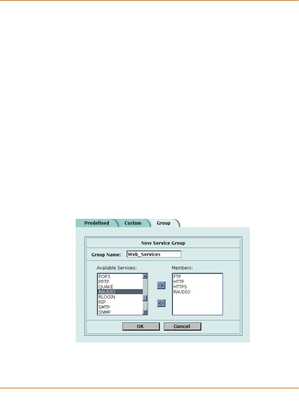
Grouping services
To make it easier to add policies, you can create groups of services and then add one
policy to provide or block access for all the services in the group. A service group can
contain predefined services and custom services in any combination. You cannot add
service groups to another service group.
To group services
1Go to Firewall > Service > Group.
2Select New.
3Type a Group Name to identify the group.
This name appears in the service list when you add a policy and cannot be the same
as a predefined service name.
The name can contain numbers (0-9), uppercase and lowercase letters (A-Z, a-z), and
the special characters - and _. Other special characters and spaces are not allowed.
4To add services to the service group, select a service from the Available Services list
and select the right arrow to copy it to the Members list.
5To remove services from the service group, select a service from the Members list and
select the left arrow to remove it from the group.
6Select OK to add the service group.
Figure 9: Adding a service group

Firewall configuration Schedules
FortiWiFi-60 Installation and Configuration Guide 177
Schedules
Use schedules to control when policies are active or inactive. You can create one-time
schedules and recurring schedules.
You can use one-time schedules to create policies that are effective once for the
period of time specified in the schedule. Recurring schedules repeat weekly. You can
use recurring schedules to create policies that are effective only at specified times of
the day or on specified days of the week.
This section describes:
•Creating one-time schedules
•Creating recurring schedules
•Adding schedules to policies
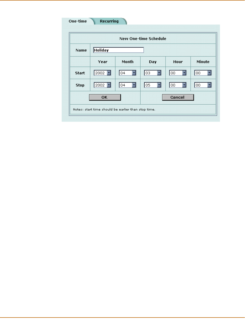
Creating one-time schedules
You can create a one-time schedule that activates or deactivates a policy for a
specified period of time. For example, your firewall might be configured with the
default policy that allows access to all services on the Internet at all times. You can
add a one-time schedule to block access to the Internet during a holiday period.
To create a one-time schedule
1Go to Firewall > Schedule > One-time.
2Select New.
3Type a Name for the schedule.
The name can contain numbers (0-9), uppercase and lowercase letters (A-Z, a-z), and
the special characters - and _. Other special characters and spaces are not allowed.
4Set the Start date and time for the schedule.
Set Start and Stop times to 00 for the schedule to be active for the entire day.
5Set the Stop date and time for the schedule.
One-time schedules use a 24-hour clock.
6Select OK to add the one-time schedule.
178 Fortinet Inc.
Schedules Firewall configuration
Figure 10: Adding a one-time schedule
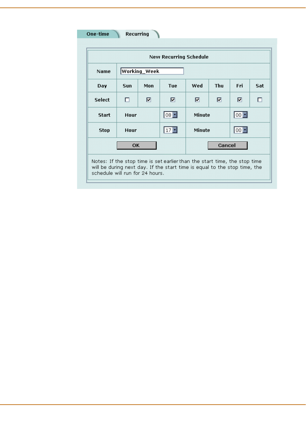
Creating recurring schedules
You can create a recurring schedule that activates or deactivates policies at specified
times of the day or on specified days of the week. For example, you might want to
prevent Internet use outside working hours by creating a recurring schedule.
If you create a recurring schedule with a stop time that occurs before the start time,
the schedule starts at the start time and finishes at the stop time on the next day. You
can use this technique to create recurring schedules that run from one day to the next.
You can also create a recurring schedule that runs for 24 hours by setting the start and
stop times to the same time.
To create a recurring schedule
1Go to Firewall > Schedule > Recurring.
2Select New to create a new schedule.
3Type a Name for the schedule.
The name can contain numbers (0-9), uppercase and lowercase letters (A-Z, a-z), and
the special characters - and _. Other special characters and spaces are not allowed.
4Select the days of the week that you want the schedule to be active on.
5Set the Start and Stop hours in between which you want the schedule to be active.
Recurring schedules use a 24-hour clock.
6Select OK to save the recurring schedule.
Firewall configuration Schedules
FortiWiFi-60 Installation and Configuration Guide 179
Figure 11: Adding a recurring schedule
Adding schedules to policies
After you create schedules, you can add them to policies to schedule when the
policies are active. You can add the new schedules to policies when you create the
policy, or you can edit existing policies and add a new schedule to them.
To add a schedule to a policy
1Go to Firewall > Policy.
2Create a new policy or edit a policy to change its schedule.
3Configure the policy as required.
4Add a schedule by selecting it from the Schedule list.
5Select OK to save the policy.
6Arrange the policy in the policy list to have the effect that you expect.
For example, to use a one-time schedule to deny access to a policy, add a policy that
matches the policy to be denied in every way. Choose the one-time schedule that you
added and set Action to DENY. Then place the policy containing the one-time
schedule in the policy list above the policy to be denied.

180 Fortinet Inc.
Virtual IPs Firewall configuration
Virtual IPs
Use virtual IPs to access IP addresses on a destination network that are hidden from
the source network by NAT security policies. To allow connections between these
networks, you must create a mapping between an address on the source network and
the real address on the destination network. This mapping is called a virtual IP.
For example, if the computer hosting your web server is located on your DMZ
network, it could have a private IP address such as 10.10.10.3. To get packets from
the Internet to the web server, you must have an external address for the web server
on the Internet. You must then add a virtual IP to the firewall that maps the external IP
address of the web server to the actual address of the web server on the DMZ
network. To allow connections from the Internet to the web server, you must then add
a WAN1->DMZ or WAN2->DMZ firewall policy and set Destination to the virtual IP.
You can create two types of virtual IPs:
This section describes:
•Adding static NAT virtual IPs
•Adding port forwarding virtual IPs
•Adding policies with virtual IPs
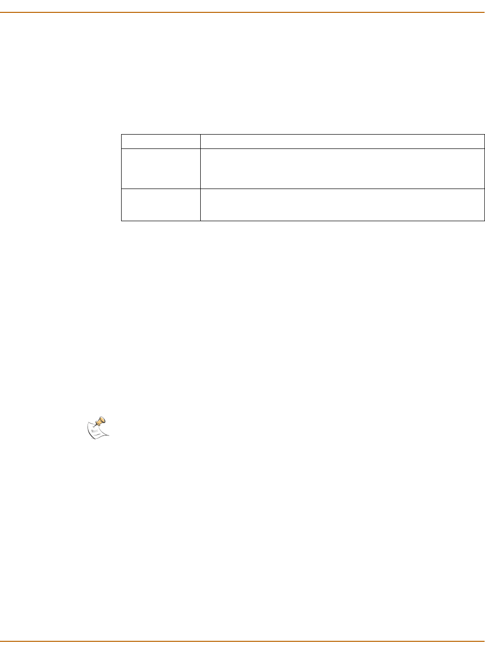
Adding static NAT virtual IPs
To add a static NAT virtual IP
1Go to Firewall > Virtual IP.
2Select New to add a virtual IP.
3Type a Name for the virtual IP.
The name can contain numbers (0-9), uppercase and lowercase letters (A-Z, a-z), and
the special characters - and _. Other special characters and spaces are not allowed.
Static NAT Used to translate an address on a source network to a hidden address on a
destination network. Static NAT translates the source address of return
packets to the address on the source network.
Port Forwarding Used to translate an address and a port number on a source network to a
hidden address and, optionally, a different port number on a destination
network. Using port forwarding you can also route packets with a specific
port number and a destination address that matches the IP address of the
interface that receives the packets. This technique is called port forwarding
or port address translation (PAT). You can also use port forwarding to
change the destination port of the forwarded packets.
Note: If you use the setup wizard to configure internal server settings, the firewall adds port
forwarding virtual IPs and policies for each server that you configure.
Note: Virtual IPs are not required in Transparent mode.
Firewall configuration Virtual IPs
FortiWiFi-60 Installation and Configuration Guide 181
4Select the virtual IP External Interface from the list.
The external interface is the interface connected to the source network that receives
the packets to be forwarded to the destination network.
You can set the virtual IP external interface to any FortiWiFi interface. Ta bl e 19
contains example virtual IP external interface settings and describes the policies that
you can add the resulting virtual IP to.
5In the Type section, select Static NAT.
6Enter the External IP Address that you want to map to an address on the destination
network.
For example, if the virtual IP provides access from the Internet to a web server on a
destination network, the external IP address must be a static IP address obtained from
your ISP for your web server. This address must be a unique address that is not used
by another host and cannot be the same as the IP address of the external interface
selected in step 4. However, this address must be routed to this interface. The virtual
IP address and the external IP address can be on different subnets.
If the IP address of the external interface selected in step 4 is set using PPPoE or
DHCP, you can enter 0.0.0.0 for the external IP address. The FortiWiFi unit substitutes
the IP address set for this external interface using PPPoE or DHCP.
7In Map to IP, type the real IP address on the destination network, for example, the IP
address of a web server on an internal network.
8Select OK to save the virtual IP.
You can now add the virtual IP to firewall policies.
Table 19: Virtual IP External Interface examples
External Interface Description
internal To map an internal address to a wan1, wan2, DMZ, or modem address. If
you select internal, the static NAT virtual IP can be added to
Internal->WAN1, Internal->WAN2, Internal->DMZ, and
Internal->modem policies.
wan1 To map an Internet address to an internal or DMZ address. If you select
wan1, the static NAT virtual IP can be added to WAN1->Internal,
WAN1->DMZ, WAN1-> WAN2, and WAN1-> modem policies.
Note: The firewall translates the source address of outbound packets from the host with the
Map to IP address to the virtual IP External IP Address, instead of the firewall external address.
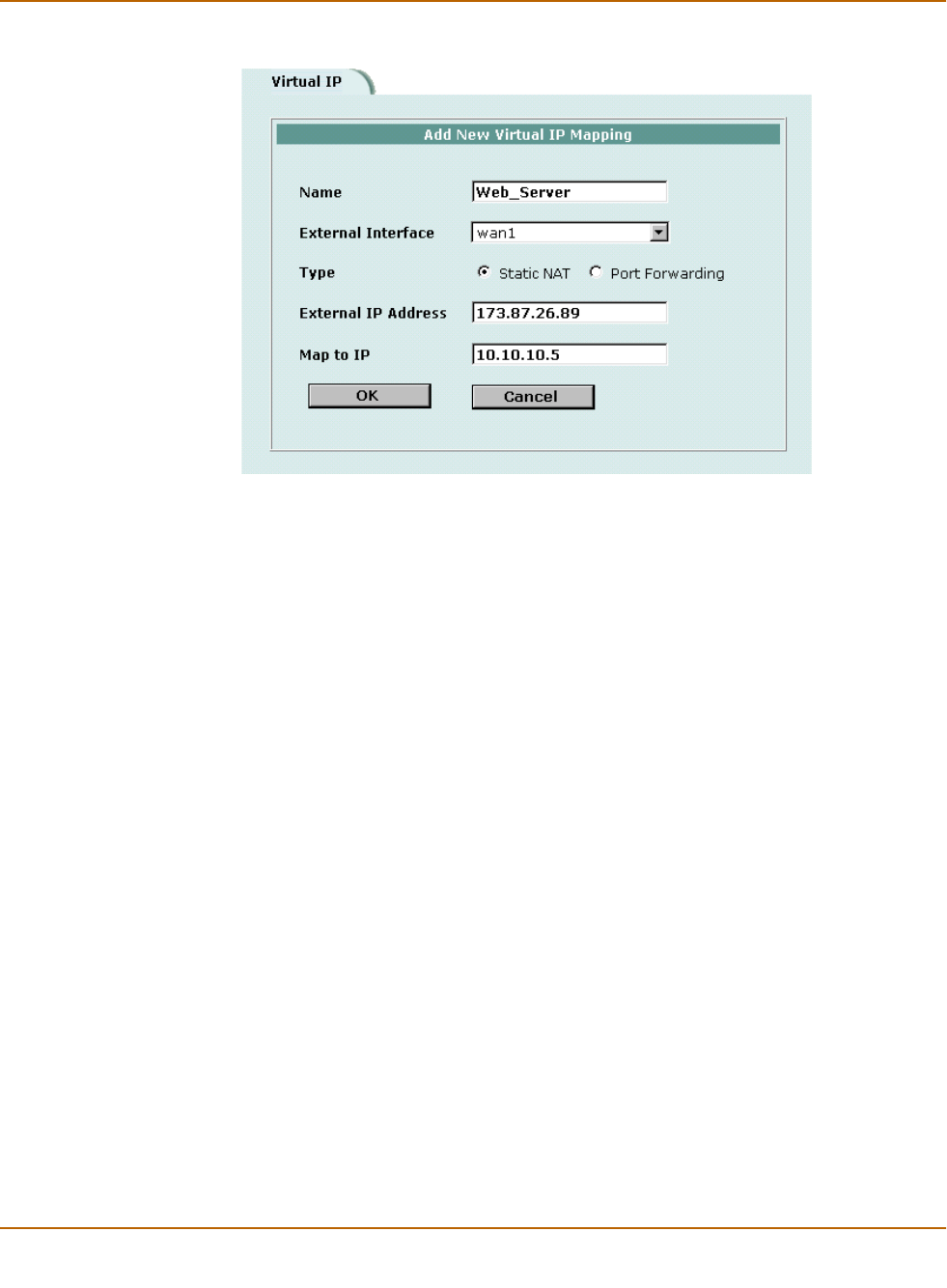
182 Fortinet Inc.
Virtual IPs Firewall configuration
Figure 12: Adding a static NAT virtual IP
Adding port forwarding virtual IPs
To add port forwarding virtual IPs
1Go to Firewall > Virtual IP.
2Select New to add a virtual IP.
3Type a Name for the virtual IP.
The name can contain numbers (0-9), uppercase and lowercase letters (A-Z, a-z), and
the special characters - and _. Other special characters and spaces are not allowed.
4Select the virtual IP External Interface from the list.
The external interface is the interface connected to the source network that receives
the packets to be forwarded to the destination network.
5In the Type section, select Port Forwarding.
6Enter the External IP Address that you want to map to an address on the destination
zone.
You can set the external IP address to the IP address of the external interface
selected in step 4 or to any other address.
If the IP address of the external interface selected in step 4 is set using PPPoE or
DHCP, you can enter 0.0.0.0 for the External IP Address. The FortiWiFi unit
substitutes the IP address set for this external interface using PPPoE or DHCP.
For example, if the virtual IP provides access from the Internet to a server on your
internal network, the external IP address must be a static IP address obtained from
your ISP for this server. This address must be a unique address that is not used by
another host. However, this address must be routed to the external interface selected
in step 4. The virtual IP address and the external IP address can be on different
subnets.
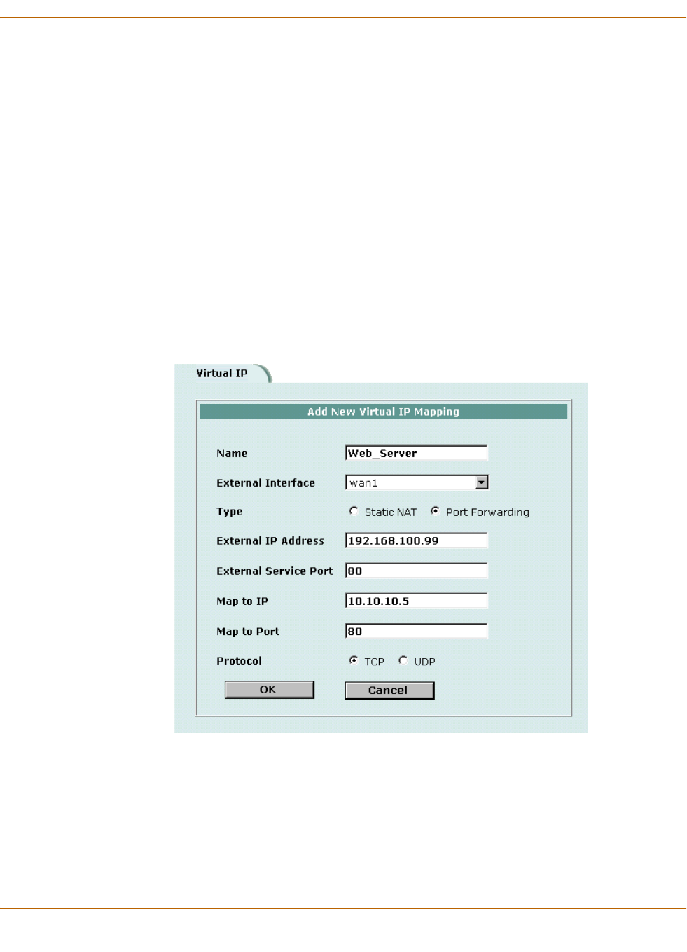
Firewall configuration Virtual IPs
FortiWiFi-60 Installation and Configuration Guide 183
7Enter the External Service Port number that you want to configure port forwarding for.
The external service port number must match the destination port of the packets to be
forwarded. For example, if the virtual IP provides access from the Internet to a web
server, the external service port number is 80 (the HTTP port).
8In Map to IP, enter the real IP address on the destination network.
For example, the real IP address could be the IP address of a web server on an
internal network.
9In Map to Port, enter the port number to be added to packets when they are
forwarded.
If you do not want to translate the port, enter the same number as the External Service
Port.
If you want to translate the port, enter the port number to which to translate the
destination port of the packets when they are forwarded by the firewall.
10 Select the protocol (TCP or UDP) that you want the forwarded packets to use.
11 Select OK to save the port forwarding virtual IP.
Figure 13: Adding a port forwarding virtual IP

184 Fortinet Inc.
IP pools Firewall configuration
Adding policies with virtual IPs
Use the following procedure to add a policy that uses a virtual IP to forward packets.
To add a policy with a virtual IP
1Go to Firewall > Policy.
2Select the type of policy that you want to add.
• The source interface must match the interface selected in the External Interface
list.
• The destination interface must match the interface connected to the network with
the Map to IP address.
3Use the following information to configure the policy.
4Select OK to save the policy.
IP pools
An IP pool (also called a dynamic IP pool) is a range of IP addresses added to a
firewall interface. If you add IP pools to an interface, you can select Dynamic IP Pool
when you configure a policy with the destination set to this interface. You can add an
IP pool if you want to add NAT mode policies that translate source addresses to
addresses randomly selected from the IP pool rather than being limited to the IP
address of the destination interface.
For example, if you add an IP pool to the internal interface, you can select Dynamic IP
pool for WAN1->Internal, WAN2->Internal and DMZ->Internal policies.
You can add multiple IP pools to any interface but only the first IP pool is used by the
firewall.
This section describes:
•Adding an IP pool
•IP Pools for firewall policies that use fixed ports
•IP pools and dynamic NAT
Source Select the source address from which users can access the server.
Destination Select the virtual IP.
Schedule Select a schedule as required.
Service Select the service that matches the Map to Service that you selected
for the port-forwarding virtual IP.
Action Set action to ACCEPT to accept connections to the internal server.
You can also select DENY to deny access.
NAT Select NAT if the firewall is protecting the private addresses on the
destination network from the source network.
Authentication Optionally select Authentication and select a user group to require
users to authenticate with the firewall before accessing the server
using port forwarding.
Log Traffic
Anti-Virus & Web filter
Select these options to log port-forwarded traffic and apply antivirus
and web filter protection to this traffic.
Firewall configuration IP pools
FortiWiFi-60 Installation and Configuration Guide 185
Adding an IP pool
To add an IP pool
1Go to Firewall > IP Pool.
2Select the interface to which to add the IP pool.
3Select New to add a new IP pool to the selected interface.
4Enter the Start IP and End IP addresses for the range of addresses in the IP pool.
The start IP and end IP must define the start and end of an address range. The start
IP must be lower than the end IP. The start IP and end IP must be on the same subnet
as the IP address of the interface that you are adding the IP pool.
5Select OK to save the IP pool.
Figure 14: Adding an IP Pool
IP Pools for firewall policies that use fixed ports
Some network configurations do not operate correctly if a NAT policy translates the
source port of packets used by the connection. NAT translates source ports to keep
track of connections for a particular service. You can select fixed port for NAT policies
to prevent source port translation. However, selecting fixed port means that only one
connection can be supported through the firewall for this service. To be able to support
multiple connections, you can add an IP pool to the destination interface, and then
select dynamic IP pool in the policy. The firewall randomly selects an IP address from
the IP pool and assigns it to each connection. In this case the number of connections
that the firewall can support is limited by the number of IP addresses in the IP pool.
IP pools and dynamic NAT
You can use IP pools for dynamic NAT. For example, your organization might have
purchased a range of Internet addresses but you might have only one Internet
connection on the external interface of your FortiWiFi unit.
You can assign one of your organization’s Internet IP addresses to the external
interface of the FortiWiFi unit. If the FortiWiFi unit is operating in NAT/Route mode, all
connections from your network to the Internet appear to come from this IP address.

186 Fortinet Inc.
IP/MAC binding Firewall configuration
If you want connections to originate from all your Internet IP addresses, you can add
this address range to an IP pool for the external interface. Then you can select
Dynamic IP Pool for all policies with the external interface as the destination. For each
connection, the firewall dynamically selects an IP address from the IP pool to be the
source address for the connection. As a result, connections to the Internet appear to
be originating from any of the IP addresses in the IP pool.
IP/MAC binding
IP/MAC binding protects the FortiWiFi unit and your network from IP spoofing attacks.
IP spoofing attacks try to use the IP address of a trusted computer to connect to, or
through, the FortiWiFi unit from a different computer. The IP address of a computer is
easy to change to a trusted address, but MAC addresses are added to ethernet cards
at the factory and are not easy to change.
You can enter the static IP addresses and corresponding MAC addresses of trusted
computers in the static IP/MAC table.
If you have trusted computers with dynamic IP addresses that are set by the FortiWiFi
DHCP server, the FortiWiFi unit adds these IP addresses and their corresponding
MAC addresses to the dynamic IP/MAC table. For information about viewing the table,
see “Viewing a DHCP server dynamic IP list” on page 129. The dynamic IP/MAC
binding table is not available in Transparent mode.
You can enable IP/MAC binding for packets in sessions connecting to the firewall or
passing through the firewall.
This section describes:
•Configuring IP/MAC binding for packets going through the firewall
•Configuring IP/MAC binding for packets going to the firewall
•Adding IP/MAC addresses
•Viewing the dynamic IP/MAC list
•Enabling IP/MAC binding
Configuring IP/MAC binding for packets going through the firewall
Use the following procedure to use IP/MAC binding to filter packets that a firewall
policy would normally allow through the firewall.
To configure IP/MAC binding for packets going through the firewall
1Go to Firewall > IP/MAC Binding > Setting.
2Select the Enable IP/MAC binding going through the firewall check box.
3Go to Firewall > IP/MAC Binding > Static IP/MAC.
Note: If you enable IP/MAC binding and change the IP address of a computer with an IP or
MAC address in the IP/MAC list, you must also change the entry in the IP/MAC list or the
computer does not have access to or through the FortiWiFi unit. You must also add the IP/MAC
address pair of any new computer that you add to your network or the new computer does not
have access to or through the FortiWiFi unit.

Firewall configuration IP/MAC binding
FortiWiFi-60 Installation and Configuration Guide 187
4Select New to add IP/MAC binding pairs to the IP/MAC binding list.
All packets that would normally be allowed through the firewall by a firewall policy are
first compared with the entries in the IP/MAC binding list. If a match is found, then the
firewall attempts to match the packet with a policy.
For example, if the IP/MAC pair IP 1.1.1.1 and 12:34:56:78:90:ab:cd is added to the
IP/MAC binding list:
• A packet with IP address 1.1.1.1 and MAC address 12:34:56:78:90:ab:cd is
allowed to go on to be matched with a firewall policy.
• A packet with IP 1.1.1.1 but with a different MAC address is dropped immediately
to prevent IP spoofing.
• A packet with a different IP address but with a MAC address of
12:34:56:78:90:ab:cd is dropped immediately to prevent IP spoofing.
• A packet with both the IP address and MAC address not defined in the IP/MAC
binding table:
• is allowed to go on to be matched with a firewall policy if IP/MAC binding is set
to Allow traffic,
• is blocked if IP/MAC binding is set to Block traffic.
Configuring IP/MAC binding for packets going to the firewall
Use the following procedure to use IP/MAC binding to filter packets that would
normally connect with the firewall (for example, when an administrator is connecting to
the FortiWiFi unit for management).
To configure IP/MAC binding for packets going to the firewall
1Go to Firewall > IP/MAC Binding > Setting.
2Select the Enable IP/MAC binding going to the firewall check box.
3Go to Firewall > IP/MAC Binding > Static IP/MAC.
4Select New to add IP/MAC binding pairs to the IP/MAC binding list.
All packets that would normally connect to the firewall are first compared with the
entries in the IP/MAC binding table.
For example, if the IP/MAC pair IP 1.1.1.1 and 12:34:56:78:90:ab:cd is added to the
IP/MAC binding list:
• A packet with IP address 1.1.1.1 and MAC address 12:34:56:78:90:ab:cd is
allowed to connect to the firewall.
• A packet with IP 1.1.1.1 but with a different MAC address is dropped immediately
to prevent IP spoofing.
• A packet with a different IP address but with a MAC address of
12:34:56:78:90:ab:cd is dropped immediately to prevent IP spoofing.
• A packet with both the IP address and MAC address not defined in the IP/MAC
binding table:
• is allowed to connect to the firewall if IP/MAC binding is set to Allow traffic,
• is blocked if IP/MAC binding is set to Block traffic.

188 Fortinet Inc.
IP/MAC binding Firewall configuration
Adding IP/MAC addresses
To add an IP/MAC address
1Go to Firewall > IP/MAC Binding > Static IP/MAC.
2Select New to add an IP address/MAC address pair.
3Enter the IP Address and the MAC Address.
You can bind multiple IP addresses to the same MAC address. You cannot bind
multiple MAC addresses to the same IP address.
However, you can set the IP address to 0.0.0.0 for multiple MAC addresses. This
means that all packets with these MAC addresses are matched with the IP/MAC
binding list.
Similarly, you can set the MAC address to 00:00:00:00:00:00 for multiple IP
addresses. This means that all packets with these IP addresses are matched with the
IP/MAC binding list.
4Type a Name for the new IP/MAC address pair.
The name can contain numbers (0-9), uppercase and lowercase letters (A-Z, a-z), and
the special characters - and _. Other special characters and spaces are not allowed.
5Select the Enable check box to enable IP/MAC binding for the IP/MAC pair.
6Select OK to save the IP/MAC binding pair.
Viewing the dynamic IP/MAC list
To view the dynamic IP/MAC list
1Go to Firewall > IP/MAC Binding > Dynamic IP/MAC.
Enabling IP/MAC binding
To enable IP/MAC binding
1Go to Firewall > IP/MAC Binding > Setting.
2Select the Enable IP/MAC binding going through the firewall check box if you want to
turn on IP/MAC binding for packets that could be matched by policies.
3Select the Enable IP/MAC binding going to the firewall check box if you want to turn
on IP/MAC binding for packets connecting to the firewall.
4Configure how IP/MAC binding handles packets with IP and MAC addresses that are
not defined in the IP/MAC list.
Select Allow traffic to allow all packets with IP and MAC address pairs that are not
added to the IP/MAC binding list.
Select Block traffic to block packets with IP and MAC address pairs that are not added
to the IP/MAC binding list.
5Select Apply to save the changes.
!Caution: Make sure that you have added the IP/MAC Address pair of your management
computer before enabling IP/MAC binding.
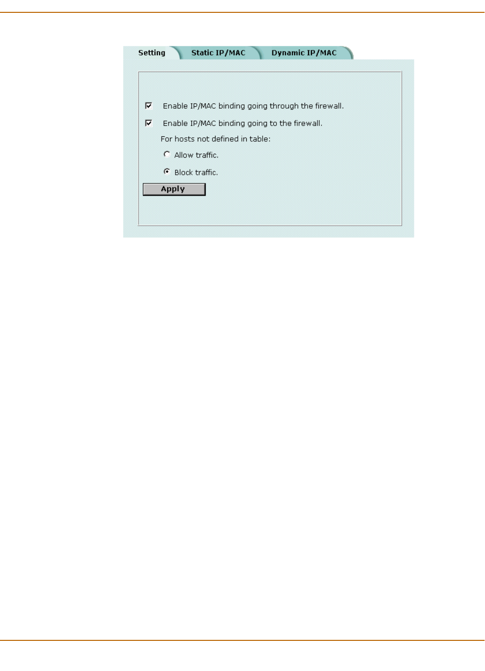
Firewall configuration Content profiles
FortiWiFi-60 Installation and Configuration Guide 189
Figure 15: IP/MAC settings
Content profiles
Use content profiles to apply different protection settings for content traffic that is
controlled by firewall policies. You can use content profiles to:
• Configure antivirus protection for HTTP, FTP, POP3, SMTP, and IMAP policies
• Configure web filtering for HTTP policies
• Configure email filtering for IMAP and POP3 policies
• Configure oversized file and email blocking for HTTP, FTP, POP3, SMTP, and
IMAP policies
• Pass fragmented email for POP3, SMTP, and IMAP policies
Using content profiles, you can build protection configurations that can be applied to
different types of firewall policies. This allows you to customize types and levels of
protection for different firewall policies.
For example, while traffic between internal and external addresses might need strict
protection, traffic between trusted internal addresses might need moderate protection.
You can configure policies for different traffic services to use the same or different
content profiles.
Content profiles can be added to NAT/Route mode and Transparent mode policies.
•Default content profiles
•Adding content profiles
•Adding content profiles to policies

190 Fortinet Inc.
Content profiles Firewall configuration
Default content profiles
The FortiWiFi unit has the following four default content profiles that are displayed on
the Firewall Content Profile page. You can use the default content profiles or create
your own.
Adding content profiles
If the default content profiles do not provide the protection that you require, you can
create custom content profiles.
To add a content profile
1Go to Firewall > Content Profile.
2Select New.
3Type a Profile Name.
4Enable the antivirus protection options that you want.
5Enable the web filtering options that you want.
Strict To apply maximum content protection to HTTP, FTP, IMAP, POP3, and
SMTP content traffic. You would not use the strict content profile under
normal circumstances but it is available if you have extreme problems with
viruses and require maximum content screening protection.
Scan To apply antivirus scanning to HTTP, FTP, IMAP, POP3, and SMTP content
traffic.
Web To apply antivirus scanning and web content blocking to HTTP content
traffic. You can add this content profile to firewall policies that control HTTP
traffic.
Unfiltered Use if you do not want to apply content protection to content traffic. You can
add this content profile to firewall policies for connections between highly
trusted or highly secure networks where content does not need to be
protected.
Anti Virus Scan Scan web, FTP, and email traffic for viruses and worms. See “Antivirus
scanning” on page 248.
File Block Delete files with blocked file patterns even if they do not contain
viruses. Enable file blocking when a virus has been found that is so
new that virus scanning does not detect it. See “File blocking” on
page 249.
Note: If both Anti Virus Scan and File Block are enabled, the FortiWiFi unit blocks files that
match enabled file patterns before they are scanned for viruses.
Web URL Block Block unwanted web pages and web sites. This option adds FortiWiFi
Web URL blocking (see “Configuring FortiWiFi Web URL blocking” on
page 257), FortiWiFi Web Pattern blocking (see “Configuring
FortiWiFi Web pattern blocking” on page 259), and Cerberian URL
filtering (see “Configuring Cerberian URL filtering” on page 260) to
HTTP traffic accepted by a policy.
Web Content Block Block web pages that contain unwanted words or phrases. See
“Content blocking” on page 254.
Web Script Filter Remove scripts from web pages. See “Script filtering” on page 262.
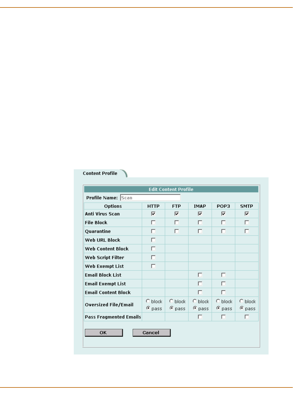
Firewall configuration Content profiles
FortiWiFi-60 Installation and Configuration Guide 191
6Enable the email filter protection options that you want.
7Enable the fragmented email and oversized file and email options that you want.
8Select OK.
Figure 16: Example content profile
Web Exempt List Exempt URLs from web filtering and virus scanning. See “Exempt
URL list” on page 263.
Email Block List Add a subject tag to email from unwanted addresses. See “Email
block list” on page 270.
Email Exempt List Exempt sender address patterns from email filtering. See “Email
exempt list” on page 271.
Email Content Block Add a subject tag to email that contains unwanted words or phrases.
See “Email banned word list” on page 268.
Oversized File/Email Block or pass files and email that exceed thresholds configured as a
percent of system memory. See “Blocking oversized files and emails”
on page 250.
Pass Fragmented
Email
Allow email messages that have been fragmented to bypass antivirus
scanning. See “Exempting fragmented email from blocking” on
page 250.

192 Fortinet Inc.
Content profiles Firewall configuration
Adding content profiles to policies
You can add content profiles to policies with action set to allow or encrypt and with
service set to ANY, HTTP, FTP, IMAP, POP3, SMTP, or a service group that includes
these services.
To add a content profile to a policy
1Go to Firewall > Policy.
2Select a policy list that contains policies that you want to add a content profile to.
For example, to enable network protection for files downloaded by internal network
users from the web, select an internal to external policy list.
3Select New to add a new policy, or choose a policy and select Edit .
4Select the Anti-Virus & Web filter check box.
5Select a content profile from the list.
6Configure the remaining policy settings, if required.
7Select OK.
8Repeat this procedure for any policies that you want to enable network protection for.

FortiWiFi-60 Installation and Configuration Guide Version 2.50
FortiWiFi-60 Installation and Configuration Guide 193
Users and authentication
FortiWiFi units support user authentication to the FortiWiFi user database, a RADIUS
server, and an LDAP server. You can add user names to the FortiWiFi user database
and then add a password to allow the user to authenticate using the internal database.
You can also add the names of RADIUS and LDAP servers. You can select RADIUS
to allow the user to authenticate using the selected RADIUS server or LDAP to allow
the user to authenticate using the selected LDAP server. You can disable a user name
so that the user cannot authenticate.
To enable authentication, you must add user names to one or more user groups. You
can also add RADIUS servers and LDAP servers to user groups. You can then select
a user group when you require authentication.
You can select user groups to require authentication for:
• any firewall policy with Action set to ACCEPT
• IPSec dialup user phase 1 configurations
• XAuth functionality for phase 1 IPSec VPN configurations
•PPTP
•L2TP
When a user enters a user name and password, the FortiWiFi unit searches the
internal user database for a matching user name. If Disable is selected for that user
name, the user cannot authenticate and the connection is dropped. If Password is
selected for that user and the password matches, the connection is allowed. If the
password does not match, the connection is dropped.
If RADIUS is selected and RADIUS support is configured and the user name and
password match a user name and password on the RADIUS server, the connection is
allowed. If the user name and password do not match a user name and password on
the RADIUS server, the connection is dropped.
If LDAP is selected and LDAP support is configured and the user name and password
match a user name and password on the LDAP server, the connection is allowed. If
the user name and password do not match a user name and password on the LDAP
server, the connection is dropped.
If the user group contains user names, RADIUS servers, and LDAP servers, the
FortiWiFi unit checks them in the order in which they have been added to the user
group.

194 Fortinet Inc.
Setting authentication timeout Users and authentication
This chapter describes:
•Setting authentication timeout
•Adding user names and configuring authentication
•Configuring RADIUS support
•Configuring LDAP support
•Configuring user groups
Setting authentication timeout
Authentication timeout controls how long authenticated firewall connections can
remain idle before users must authenticate again to get access through the firewall.
To set authentication timeout
1Go to System > Config > Options.
2In Auth Timeout, type a number, in minutes.
The default authentication timeout is 15 minutes.
Adding user names and configuring authentication
Use the following procedures to add user names and configure authentication.
This section describes:
•Adding user names and configuring authentication
•Deleting user names from the internal database
Adding user names and configuring authentication
To add a user name and configure authentication
1Go to User > Local.
2Select New to add a new user name.
3Type the User Name.
The user name can contain numbers (0-9), uppercase and lowercase letters (A-Z,
a-z), and the special characters - and _. Other special characters and spaces are not
allowed.
4Select one of the following authentication configurations:
Disable Prevent this user from authenticating.
Password Enter the password that this user must use to authenticate. The password
should be at least six characters long. The password can contain numbers
(0-9), uppercase and lowercase letters (A-Z, a-z), and the special characters
- and _. Other special characters and spaces are not allowed.
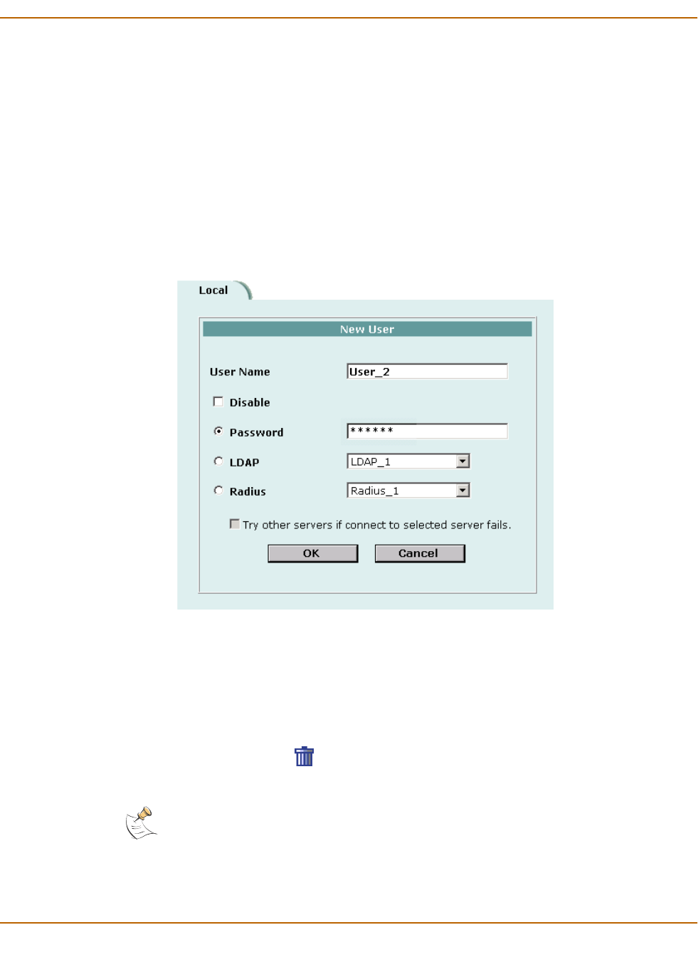
Users and authentication Adding user names and configuring authentication
FortiWiFi-60 Installation and Configuration Guide 195
5Select the Try other servers if connect to selected server fails check box if you have
selected Radius and you want the FortiWiFi unit to try to connect to other RADIUS
servers added to the FortiWiFi RADIUS configuration.
6Select OK.
Figure 17: Adding a user name
Deleting user names from the internal database
You cannot delete user names that have been added to user groups. Remove user
names from user groups before deleting them.
To delete a user name from the internal database
1Go to User > Local.
2Select Delete User for the user name that you want to delete.
3Select OK.
LDAP Require the user to authenticate to an LDAP server. Select the name of the
LDAP server to which the user must authenticate. You can only select an
LDAP server that has been added to the FortiWiFi LDAP configuration. See
“Configuring LDAP support” on page 197.
Radius Require the user to authenticate to a RADIUS server. Select the name of the
RADIUS server to which the user must authenticate. You can only select a
RADIUS server that has been added to the FortiWiFi RADIUS configuration.
See “Configuring RADIUS support” on page 196.
Note: Deleting the user name deletes the authentication configured for the user.
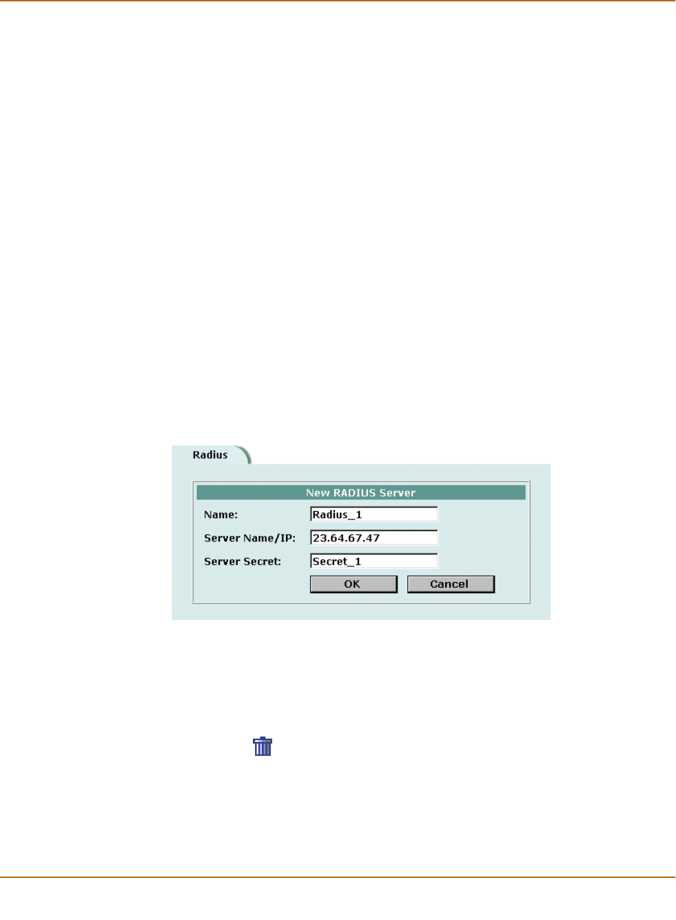
196 Fortinet Inc.
Configuring RADIUS support Users and authentication
Configuring RADIUS support
If you have configured RADIUS support and a user is required to authenticate using a
RADIUS server, the FortiWiFi unit contacts the RADIUS server for authentication.
This section describes:
•Adding RADIUS servers
•Deleting RADIUS servers
Adding RADIUS servers
To add a RADIUS server
1Go to User > RADIUS.
2Select New to add a new RADIUS server.
3Type the Name of the RADIUS server.
You can type any name. The name can contain numbers (0-9), uppercase and
lowercase letters (A-Z, a-z), and the special characters - and _. Other special
characters and spaces are not allowed.
4Enter the Server Name or IP address of the RADIUS server.
5Enter the RADIUS server secret.
6Select OK.
Figure 18: Example RADIUS configuration
Deleting RADIUS servers
You cannot delete a RADIUS server that has been added to a user group.
To delete a RADIUS server
1Go to User > RADIUS.
2Select Delete beside the RADIUS server name that you want to delete.
3Select OK.

Users and authentication Configuring LDAP support
FortiWiFi-60 Installation and Configuration Guide 197
Configuring LDAP support
If you have configured LDAP support and a user is required to authenticate using an
LDAP server, the FortiWiFi unit contacts the LDAP server for authentication. To
authenticate with the FortiWiFi unit, the user enters a user name and password. The
FortiWiFi unit sends this user name and password to the LDAP server. If the LDAP
server can authenticate the user, the user is successfully authenticated with the
FortiWiFi unit. If the LDAP server cannot authenticate the user, the connection is
refused by the FortiWiFi unit.
The FortiWiFi unit supports LDAP protocol functionality defined in RFC2251 for
looking up and validating user names and passwords. ForitGate LDAP supports all
LDAP servers compliant with LDAP v3.
FortiWiFi LDAP support does not extend to proprietary functionality, such as
notification of password expiration, that is available from some LDAP servers.
FortiWiFi LDAP support does not supply information to the user about why
authentication failed.
LDAP user authentication is supported for PPTP, L2TP, IPSec VPN, and firewall
authentication. With PPTP, L2TP, and IPSec VPN, PAP (packet authentication
protocol) is supported and CHAP (Challenge-Handshake Authentication Protocol) is
not.
This section describes:
•Adding LDAP servers
•Deleting LDAP servers
Adding LDAP servers
To add an LDAP server
1Go to User > LDAP.
2Select New to add a new LDAP server.
3Type the Name of the LDAP server.
You can type any name. The name can contain numbers (0-9), uppercase and
lowercase letters (A-Z, a-z), and the special characters - and _. Other special
characters and spaces are not allowed.
4Enter the Server Name or IP address of the LDAP server.
5Enter the Server Port used to communicate with the LDAP server.
By default LDAP uses port 389.
6Enter the common name identifier for the LDAP server.
The common name identifier for most LDAP servers is cn. However some servers use
other common name identifiers such as uid.
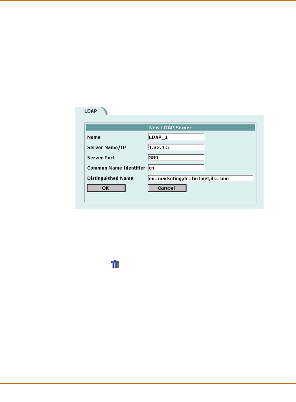
198 Fortinet Inc.
Configuring LDAP support Users and authentication
7Enter the distinguished name used to look up entries on the LDAP server.
Enter the base distinguished name for the server using the correct X.500 or LDAP
format. The FortiWiFi unit passes this distinguished name unchanged to the server.
For example, you could use the following base distinguished name:
ou=marketing,dc=fortinet,dc=com
where ou is organization unit and dc is domain component
You can also specify multiple instances of the same field in the distinguished name,
for example, to specify multiple organization units:
ou=accounts,ou=marketing,dc=fortinet,dc=com
8Select OK.
Figure 19: Example LDAP configuration
Deleting LDAP servers
You cannot delete an LDAP server that has been added to a user group.
To delete an LDAP server
1Go to User > LDAP.
2Select Delete beside the LDAP server name that you want to delete.
3Select OK.

Users and authentication Configuring user groups
FortiWiFi-60 Installation and Configuration Guide 199
Configuring user groups
To enable authentication, you must add user names, RADIUS servers, and LDAP
servers to one or more user groups. You can then select a user group when you
require authentication. You can select a user group to configure authentication for:
• Policies that require authentication. Only users in the selected user group or users
that can authenticate with the RADIUS servers added to the user group can
authenticate with these policies.
• IPSec VPN Phase 1 configurations for dialup users. Only users in the selected
user group can authenticate to use the VPN tunnel.
• XAuth for IPSec VPN Phase 1 configurations. Only users in the selected user
group can be authenticated using XAuth.
• The FortiWiFi PPTP configuration. Only users in the selected user group can use
PPTP.
• The FortiWiFi L2TP configuration. Only users in the selected user group can use
L2TP.
When you add user names, RADIUS servers, and LDAP servers to a user group, the
order in which they are added determines the order in which the FortiWiFi unit checks
for authentication. If user names are first, then the FortiWiFi unit checks for a match
with these local users. If a match is not found, the FortiWiFi unit checks the RADIUS
or LDAP server. If a RADIUS or LDAP server is added first, the FortiWiFi unit checks
the server and then the local users.
If the user group contains users, RADIUS servers, and LDAP servers, the FortiWiFi
unit checks them in the order in which they have been added to the user group.
This section describes:
•Adding user groups
•Deleting user groups
Adding user groups
Use the following procedure to add user groups to the FortiWiFi configuration. You
can add user names, RADIUS servers, and LDAP servers to user groups.
To add a user group
1Go to User > User Group.
2Select New to add a new user group.
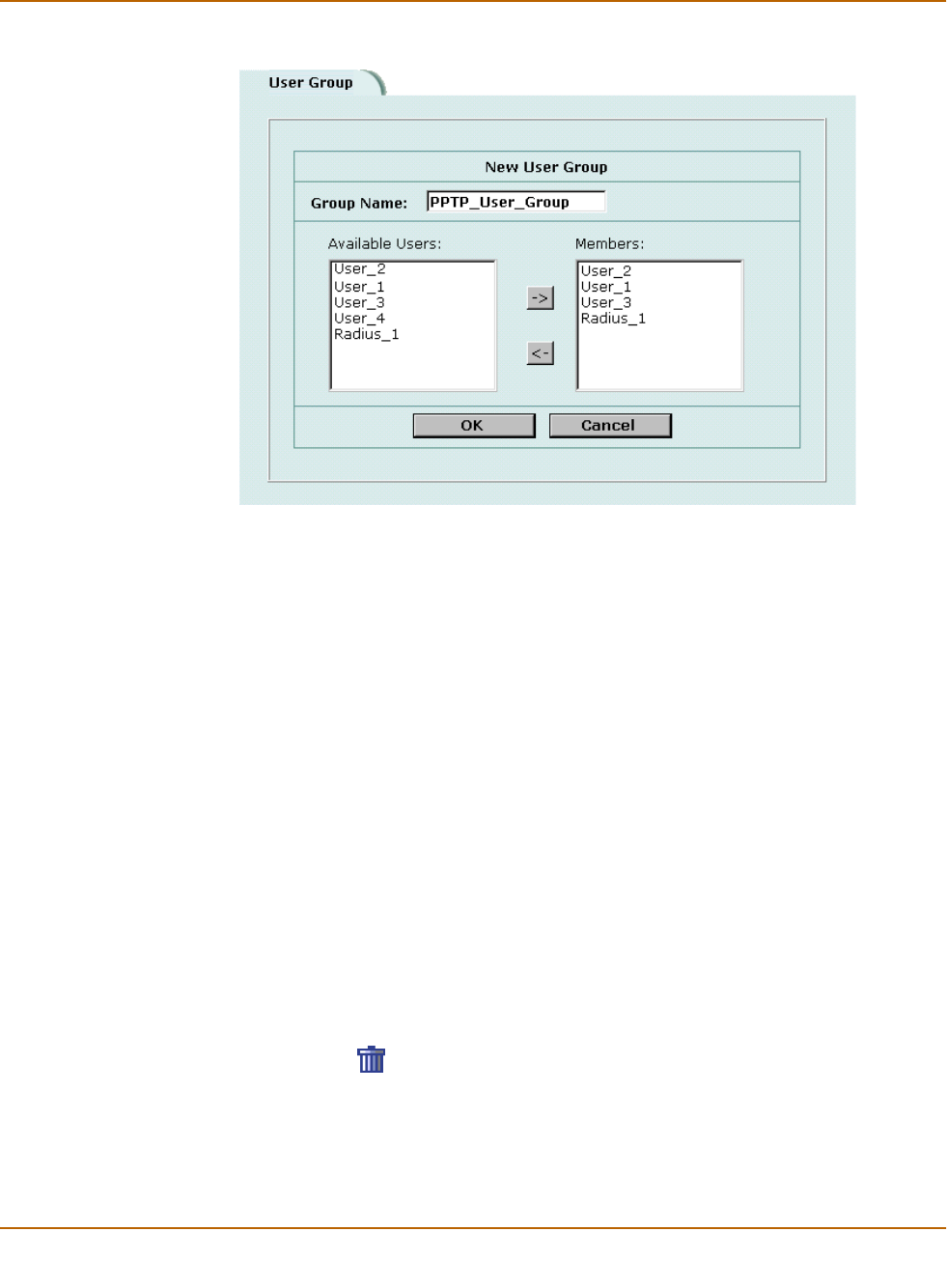
200 Fortinet Inc.
Configuring user groups Users and authentication
Figure 20: Adding a user group
3Enter a Group Name to identify the user group.
The name can contain numbers (0-9), uppercase and lowercase letters (A-Z, a-z), and
the special characters - and _. Other special characters and spaces are not allowed.
4To add users to the user group, select a user from the Available Users list and select
the right arrow to add the name to the Members list.
5To add a RADIUS server to the user group, select a RADIUS server from the Available
Users list and select the right arrow to add the RADIUS server to the Members list.
6To add an LDAP server to the user group, select an LDAP server from the Available
Users list and select the right arrow to add the LDAP server to the Members list.
7To remove users, RADIUS servers, or LDAP servers from the user group, select a
user, RADIUS server, or LDAP server from the Members list and select the left arrow
to remove the name, RADIUS server, or LDAP server from the group.
8Select OK.
Deleting user groups
You cannot delete user groups that have been selected in a policy, a dialup user
phase 1 configuration, or a PPTP or L2TP configuration.
To delete a user group
1Go to User > User Group
2Select Delete beside the user group that you want to delete.
3Select OK.

FortiWiFi-60 Installation and Configuration Guide Version 2.50
FortiWiFi-60 Installation and Configuration Guide 201
IPSec VPN
A Virtual Private Network (VPN) is an extension of a private network that
encompasses links across shared or public networks such as the Internet. For
example, a company that has two offices in different cities, each with its own private
network, can use a VPN to create a secure tunnel between the offices. Similarly, a
teleworker can use a VPN client for remote access to a private office network. In both
cases, the secure connection appears to the user as a private network
communication, even though the communication is over a public network.
Secure VPN connections are enabled by a combination of tunneling, data encryption,
and authentication. Tunneling encapsulates data so that it can be transferred over the
public network. Instead of being sent in its original format, the data frames are
encapsulated within an additional header and then routed between tunnel endpoints.
Upon arrival at the destination endpoint, the data is decapsulated and forwarded to its
destination within the private network.
Encryption changes a data stream from clear text (something that a human or a
program can interpret) to cipher text (something that cannot be interpreted). The
information is encrypted and decrypted using mathematical algorithms known as
keys.
Authentication provides a means to verify the origin of a packet and the integrity of its
contents. Authentication is done using checksums calculated with keyed hash
function algorithms.
This chapter provides an overview about how to configure FortiWiFi IPSec VPN. For a
complete description of FortiWiFi VPN, see the FortiGate VPN Guide.
•Key management
•Manual key IPSec VPNs
•AutoIKE IPSec VPNs
•Managing digital certificates
•Configuring encrypt policies
•IPSec VPN concentrators
•Monitoring and Troubleshooting VPNs

202 Fortinet Inc.
Key management IPSec VPN
Key management
There are three basic elements in any encryption system:
• an algorithm that changes information into code,
• a cryptographic key that serves as a secret starting point for the algorithm,
• a management system to control the key.
IPSec provides two ways to handle key exchange and management:
•Manual Keys
•Automatic Internet Key Exchange (AutoIKE) with pre-shared keys or certificates
Manual Keys
When using manual keys, matching security settings must be entered at both ends of
the tunnel. These settings, which include both the encryption and authentication keys,
must be kept secret so that unauthorized parties cannot decrypt the data, even if they
know which encryption algorithm is being used.
Automatic Internet Key Exchange (AutoIKE) with pre-shared keys or certificates
For using multiple tunnels, an automated system of key management is required.
IPSec supports the automated generation and negotiation of keys using the Internet
Key Exchange protocol. This method of key management is referred to as AutoIKE.
Fortinet supports AutoIKE with pre-shared keys and AutoIKE with certificates.
AutoIKE with pre-shared keys
If both peers in a session are configured with the same pre-shared key, they can use it
to authenticate themselves to each other. The peers do not send the key to each
other. Instead, as part of the security negotiation process, they use it in combination
with a Diffie-Hellman group to create a session key. The session key is used for
encryption and authentication and is automatically regenerated by IKE during the
communication session.
Pre-shared keys are similar to manual keys in that they require the network
administrator to distribute and manage matching information at the VPN peer sites.
Whenever a pre-shared key changes, the administrator must update both sites.
AutoIKE with certificates
This method of key management involves a trusted third party, the certificate authority
(CA). Each peer in a VPN is first required to generate a set of keys, known as a
public/private key pair. The CA signs the public key for each peer, creating a signed
digital certificate. The peer then contacts the CA to retrieve their own certificates, plus
that of the CA. After the certificates are uploaded to the FortiWiFi units and
appropriate IPSec tunnels and policies are configured, the peers are ready to
communicate. As they do, IKE manages the exchange of certificates, sending signed
digital certificates from one peer to another. The signed digital certificates are
validated by the presence of the CA certificate at each end. With authentication
complete, the IPSec tunnel is then established.

IPSec VPN Manual key IPSec VPNs
FortiWiFi-60 Installation and Configuration Guide 203
In some respects, certificates are simpler to manage than manual keys or pre-shared
keys. For this reason, certificates are best suited to large network deployments.
Manual key IPSec VPNs
When using manual keys, complementary security parameters must be entered at
both ends of the tunnel. In addition to encryption and authentication algorithms and
keys, the security parameter index (SPI) is required. The SPI is an arbitrary value that
defines the structure of the communication between the peers. With other methods,
the SPI is generated automatically but with the manual key configuration it must be
entered as part of the VPN setup.
The encryption and authentication keys must match on the local and remote peers,
that is, the SPI values must be mirror images of each other. After you enter these
values, the VPN tunnel can start without a need for the authentication and encryption
algorithms to be negotiated. Provided you entered correct, complementary values, the
tunnels are established between the peers. This means that the tunnel already exists
between the peers. As a result, when traffic matches a policy requiring the tunnel, it
can be authenticated and encrypted immediately.
•General configuration steps for a manual key VPN
•Adding a manual key VPN tunnel
General configuration steps for a manual key VPN
A manual key VPN configuration consists of a manual key VPN tunnel, the source and
destination addresses for both ends of the tunnel, and an encrypt policy to control
access to the VPN tunnel.
To create a manual key VPN configuration
1Add a manual key VPN tunnel. See “Adding a manual key VPN tunnel” on page 203.
2Configure an encrypt policy that includes the tunnel, source address, and destination
address for both ends of the tunnel. See “Configuring encrypt policies” on page 215.
Adding a manual key VPN tunnel
Configure a manual key tunnel to create an IPSec VPN tunnel between the FortiWiFi
unit and a remote IPSec VPN client or gateway that is also using manual key.
To add a manual key VPN tunnel
1Go to VPN > IPSec > Manual Key.
2Select New to add a new manual key VPN tunnel.
3Type a VPN Tunnel Name.
The name can contain numbers (0-9), uppercase and lowercase letters (A-Z, a-z), and
the special characters - and _. Other special characters and spaces are not allowed.
4Enter the Local SPI.
The Local Security Parameter Index is a hexadecimal number of up to eight digits
(digits can be 0 to 9, a to f) in the range bb8 to FFFFFFF. This number must be added
to the Remote SPI at the opposite end of the tunnel.

204 Fortinet Inc.
Manual key IPSec VPNs IPSec VPN
5Enter the Remote SPI.
The Remote Security Parameter Index is a hexadecimal number of up to eight digits
(digits can be 0 to 9, a to f) in the range bb8 to FFFFFFF. This number must be added
to the Local SPI at the opposite end of the tunnel.
6Enter the Remote Gateway.
This is the external IP address of the FortiWiFi unit or other IPSec gateway at the
opposite end of the tunnel.
7Select an Encryption Algorithm from the list.
Use the same algorithm at both ends of the tunnel.
8Enter the Encryption Key.
Each two-character combination entered in hexadecimal format represents one byte.
Depending on the encryption algorithm that you select, you might be required to enter
the key in multiple segments. Use the same encryption key at both ends of the tunnel.
9Select an Authentication Algorithm from the list.
Use the same algorithm at both ends of the tunnel.
10 Enter the Authentication Key.
Each two-character combination entered in hexadecimal format represents one byte.
Use the same authentication key at both ends of the tunnel.
11 Select a concentrator if you want the tunnel to be part of a hub and spoke VPN
configuration. See “Adding a VPN concentrator” on page 220.
12 Select OK to save the manual key VPN tunnel.
DES Enter a 16-character (8 byte) hexadecimal number (0-9, A-F).
3DES Enter a 48-character (24 byte) hexadecimal number (0-9, A-F). Separate the
number into three segments of 16 characters.
AES128 Enter a 32-character (16 byte) hexadecimal number (0-9, A-F). Separate the
number into two segments of 16 characters.
AES192 Enter a 48-character (24 byte) hexadecimal number (0-9, A-F). Separate the
number into three segments of 16 characters.
AES256 Enter a 64-character (32 byte) hexadecimal number (0-9, A-F). Separate the
number into four segments of 16 characters.
MD5 Enter a 32-character (16 byte) hexadecimal number (0-9, A-F). Separate the
number into two segments of 16 characters.
SHA1 Enter a 40-character (20 byte) hexadecimal number (0-9, A-F). Separate the
number into two segments—the first of 16 characters; the second of 24
characters.

IPSec VPN AutoIKE IPSec VPNs
FortiWiFi-60 Installation and Configuration Guide 205
AutoIKE IPSec VPNs
FortiWiFi units support two methods of Automatic Internet Key Exchange (AutoIKE)
for establishing IPSec VPN tunnels: AutoIKE with pre-shared keys and AutoIKE with
digital certificates.
•General configuration steps for an AutoIKE VPN
•Adding a phase 1 configuration for an AutoIKE VPN
•Adding a phase 2 configuration for an AutoIKE VPN
General configuration steps for an AutoIKE VPN
An AutoIKE VPN configuration consists of phase 1 and phase 2 configuration
parameters, the source and destination addresses for both ends of the tunnel, and an
encrypt policy to control access to the VPN tunnel.
To create an AutoIKE VPN configuration
1Add the phase 1 parameters. See “Adding a phase 1 configuration for an AutoIKE
VPN” on page 205.
2Add the phase 2 parameters. See “Adding a phase 2 configuration for an AutoIKE
VPN” on page 210.
3Configure an encrypt policy that includes the tunnel, source address, and destination
address for both ends of the tunnel. See “Configuring encrypt policies” on page 215.
Adding a phase 1 configuration for an AutoIKE VPN
When you add a phase 1 configuration, you define the terms by which the FortiWiFi
unit and a remote VPN peer (gateway or client) authenticate themselves to each other
prior to establishing an IPSec VPN tunnel.
The phase 1 configuration is related to the phase 2 configuration. In phase 1 the VPN
peers are authenticated; in phase 2 the tunnel is established. You have the option to
use the same phase 1 parameters to establish multiple tunnels. In other words, the
same remote VPN peer (gateway or client) can have multiple tunnels to the local VPN
peer (the FortiWiFi unit).
When the FortiWiFi unit receives an IPSec VPN connection request, it authenticates
the VPN peers according to the phase 1 parameters. Then, depending on the source
and destination addresses of the request, it starts an IPSec VPN tunnel and applies
an encrypt policy.
To add a phase 1 configuration
1Go to VPN > IPSEC > Phase 1.
2Select New to add a new phase 1 configuration.
Note: Prior to configuring an AutoIKE VPN that uses digital certificates, you must add the CA
and local certificates to the FortiWiFi unit. For information about digital certificates, see
“Managing digital certificates” on page 212.

206 Fortinet Inc.
AutoIKE IPSec VPNs IPSec VPN
3Type a Gateway Name for the remote VPN peer.
The remote VPN peer can be either a gateway to another network or an individual
client on the Internet.
The name can contain numbers (0-9), uppercase and lowercase letters (A-Z, a-z), and
the special characters - and _. Other special characters and spaces are not allowed.
4Select a Remote Gateway address type.
• If the remote VPN peer has a static IP address, select Static IP Address.
• If the remote VPN peer has a dynamically assigned IP address (DHCP or PPPoE),
or if the remote VPN peer has a static IP address that is not required in the peer
identification process, select Dialup User.
Depending on the Remote Gateway address type you selected, other fields become
available.
5Select Aggressive or Main (ID Protection) mode.
When using aggressive mode, the VPN peers exchange identifying information in the
clear. When using main mode, identifying information is hidden.
The VPN peers must use the same mode.
6Configure the P1 Proposal.
Select up to three encryption and authentication algorithm combinations to propose
for phase 1.
The VPN peers must use the same P1 proposal settings.
7Select the DH Group(s).
Select one or more Diffie-Hellman groups to propose for phase 1.
As a general rule, the VPN peers should use the same DH Group settings.
8Enter the Keylife.
The keylife is the amount of time in seconds before the phase 1 encryption key
expires. When the key expires, a new key is generated without interrupting service.
P1 proposal keylife can be from 120 to 172,800 seconds.
9For Authentication Method, select Preshared Key or RSA Signature.
• Preshared Key: Enter a key that is shared by the VPN peers. The key must contain
at least 6 printable characters and should only be known by network
administrators. For optimum protection against currently known attacks, make sure
the key consists of a minimum of 16 randomly chosen alphanumeric characters.
• RSA Signature: Select a local certificate that has been digitally signed by the
certificate authority (CA). To add a local certificate to the FortiWiFi unit, see
“Obtaining a signed local certificate” on page 212.
Remote Gateway: Static IP Address
IP Address If you select Static IP Address, the IP Address field appears. Enter the IP
address of the remote IPSec VPN gateway or client that can connect to the
FortiWiFi unit. This is a mandatory entry.
Remote Gateway: Dialup User
Peer Options If you select Dialup User, the Peer Options become available under
Advanced Options. Use the Peer Options to authenticate remote VPN
peers with peer IDs during phase 1 negotiations.

IPSec VPN AutoIKE IPSec VPNs
FortiWiFi-60 Installation and Configuration Guide 207
10 Configure the Local ID the that the FortiWiFi unit sends to the remote VPN peer.
• Preshared key: If the FortiWiFi unit is functioning as a client and uses its ID to
authenticate itself to the remote VPN peer, enter an ID. If no ID is specified, the
FortiWiFi unit transmits its IP address.
• RSA Signature: No entry is required because the Local ID field contains the
Distinguished Name (DN) of the certificate associated with this phase 1
configuration. The DN identifies the owner of the certificate and includes, as a
minimum, a Common Name (CN). The DN is transmitted in place of an ID or IP
address.
Configuring advanced options
To configure phase 1 advanced options
1Select Advanced Options.
2Select a Peer Option if you want to authenticate remote VPN peers by the ID that they
transmit during phase 1.
3Optionally, configure XAuth.
XAuth (IKE eXtended Authentication) authenticates VPN peers at the user level. If the
the FortiWiFi unit (the local VPN peer) is configured as an XAuth server, it
authenticates remote VPN peers by referring to a user group. The users contained in
the user group can be configured locally on the FortiWiFi unit or on remotely located
LDAP or RADIUS servers. If the FortiWiFi unit is configured as an XAuth client, it
provides a user name and password when it is challenged.
Accept any peer ID Select to accept any peer ID (and therefore not authenticate
remote VPN peers by peer ID).
Accept this peer ID Select to authenticate a specific VPN peer or a group of VPN
peers with a shared user name (ID) and password (pre-
shared key). Also add the peer ID.
Accept peer ID in dialup group Select to authenticate each remote VPN peer with a unique
user name (ID) and password (pre-shared key). Also select
a dialup group (user group).
Configure the user group prior to configuring this peer
option.
XAuth: Enable as a Client
Name Enter the user name the local VPN peer uses to authenticate itself to the
remote VPN peer.
Password Enter the password the local VPN peer uses to authenticate itself to the
remote VPN peer.

208 Fortinet Inc.
AutoIKE IPSec VPNs IPSec VPN
4Optionally, configure NAT Traversal.
5Optionally, configure Dead Peer Detection.
Use these settings to monitor the status of the connection between VPN peers. DPD
allows dead connections to be cleaned up and new VPN tunnels established. DPD is
not supported by all vendors.
6Select OK to save the phase 1 parameters.
XAuth: Enable as a Server
Encryption
method
Select the encryption method used between the XAuth client, the FortiWiFi
unit and the authentication server.
PAP— Password Authentication Protocol.
CHAP—Challenge-Handshake Authentication Protocol.
MIXED—Select MIXED to use PAP between the XAuth client and the
FortiWiFi unit, and CHAP between the FortiWiFi unit and the authentication
server.
Use CHAP whenever possible. Use PAP if the authentication server does
not support CHAP. (Use PAP with all implementations of LDAP and some
implementations of Microsoft RADIUS). Use MIXED if the authentication
server supports CHAP but the XAuth client does not. (Use MIXED with the
Fortinet Remote VPN Client.).
Usergroup Select a group of users to be authenticated by XAuth. The individual users
within the group can be authenticated locally or by one or more LDAP or
RADIUS servers.
The user group must be added to the FortiWiFi configuration before it can
be selected here.
Enable Select Enable if you expect the IPSec VPN traffic to go through a gateway
that performs NAT. If no NAT device is detected, enabling NAT traversal
has no effect. Both ends of the VPN (both VPN peers) must have the same
NAT traversal setting.
Keepalive
Frequency
If you enable NAT-traversal, you can change the number of seconds in the
Keepalive Frequency field. This number specifies, in seconds, how
frequently empty UDP packets are sent through the NAT device to ensure
that the NAT mapping does not change until P1 and P2 keylife expires. The
keepalive frequency can be from 0 to 900 seconds.
Enable Select Enable to enable DPD between the local and remote peers.
Short Idle Set the time, in seconds, that a link must remain unused before the local
VPN peer considers it to be idle. After this period of time expires, whenever
the local peer sends traffic to the remote VPN peer it also sends a DPD
probe to determine the status of the link. To control the length of time that
the FortiWiFi unit takes to detect a dead peer with DPD probes, configure
the Retry Count and the Retry Interval.
Retry Count Set the number of times that the local VPN peer retries the DPD probe
before it considers the channel to be dead and tears down the security
association (SA). To avoid false negatives because of congestion or other
transient failures, set the retry count to a sufficiently high value for your
network.
Retry Interval Set the time, in seconds, that the local VPN peer unit waits between
retrying DPD probes.
Long Idle Set the time, in seconds, that a link must remain unused before the local
VPN peer pro-actively probes its state. After this period of time expires, the
local peer sends a DPD probe to determine the status of the link even if
there is no traffic between the local peer and the remote peer.
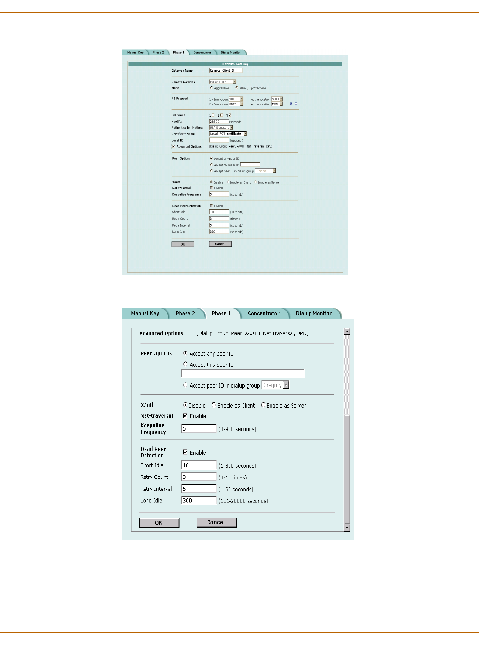
IPSec VPN AutoIKE IPSec VPNs
FortiWiFi-60 Installation and Configuration Guide 209
Figure 21: Adding a phase 1 configuration (Standard options)
Figure 22: Adding a phase 1 configuration (Advanced options)

210 Fortinet Inc.
AutoIKE IPSec VPNs IPSec VPN
Adding a phase 2 configuration for an AutoIKE VPN
Add a phase 2 configuration to specify the parameters used to create and maintain a
VPN tunnel between the local VPN peer (the FortiWiFi unit) and the remote VPN peer
(the VPN gateway or client).
To add a phase 2 configuration
1Go to VPN > IPSEC > Phase 2.
2Select New to add a new phase 2 configuration.
3Enter a Tunnel Name.
The name can contain numbers (0-9), uppercase and lowercase letters (A-Z, a-z), and
the special characters - and _. Other special characters and spaces are not allowed.
4Select a Remote Gateway to associate with the VPN tunnel.
A remote gateway can be either a gateway to another network or an individual client
on the Internet. Remote gateways are added as part of the phase 1 configuration. For
details, see “Adding a phase 1 configuration for an AutoIKE VPN” on page 205.
Choose either a single DIALUP remote gateway, or up to three STATIC remote
gateways. Multiple STATIC remote gateways are necessary if you are configuring
IPSec redundancy.
5Configure the P2 Proposal.
Select up to three encryption and authentication algorithm combinations to propose
for phase 2.
The VPN peers must use the same P2 proposal settings.
6Optionally, enable Replay Detection.
Replay detection protects the VPN tunnel from replay attacks.
7Optionally, enable Perfect Forward Secrecy (PFS).
PFS improves security by forcing a new Diffie-Hellman exchange whenever keylife
expires.
8Select the DH Group(s).
The VPN peers must use the same DH Group settings.
9Enter the Keylife.
The keylife causes the phase 2 key to expire after a specified time, after a specified
number of Kbytes of data have been processed by the VPN tunnel, or both. If you
select both, the key does not expire until both the time has passed and the number of
Kbytes have been processed.
When the key expires, a new key is generated without interrupting service. P2
proposal keylife can be from 120 to 172800 seconds or from 5120 to 99999 Kbytes.
Note: Adding a Phase 2 configuration is the same for pre-shared key and certification VPNs.
Note: Do not select replay detection if you have also selected Null Authentication for the P2
Proposal.
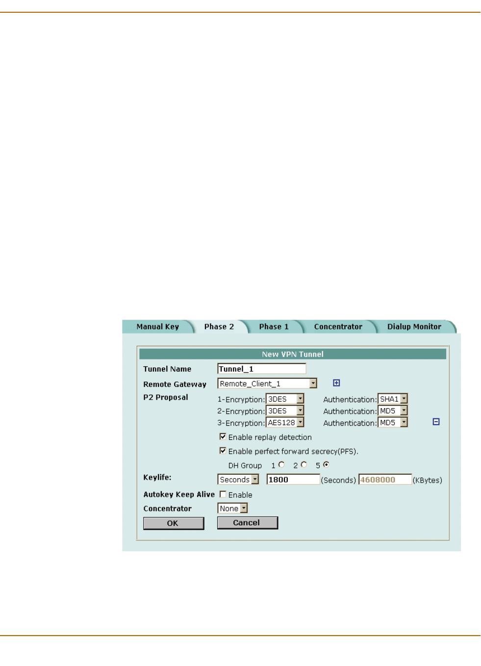
IPSec VPN AutoIKE IPSec VPNs
FortiWiFi-60 Installation and Configuration Guide 211
10 Enable Autokey Keep Alive if you want to keep the VPN tunnel running even if no data
is being processed.
11 Select a concentrator if you want the tunnel to be part of a hub and spoke VPN
configuration.
If you use the procedure, “Adding a VPN concentrator” on page 220 to add the tunnel
to a concentrator, the next time you open the tunnel, the Concentrator field displays
the name of the concentrator to which you added the tunnel.
12 Select a Quick Mode Identity.
13 Select OK to save the AutoIKE key VPN tunnel.
Figure 23: Adding a phase 2 configuration
Use selectors from policy Select this option for policy-based VPNs. A policy-based
VPN uses an encrypt policy to select which VPN tunnel to
use for the connection. In this configuration, the VPN tunnel
is referenced directly from the encrypt policy.
You must select this option if both VPN peers are FortiWiFi
units.
Use wildcard selectors Select this option for routing-based VPNs. A routing-based
VPN uses routing information to select which VPN tunnel to
use for the connection. In this configuration, the tunnel is
referenced indirectly by a route that points to a tunnel
interface.
You must select this option if the remote VPN peer is a non-
FortiWiFi unit that has been configured to operate in tunnel
interface mode.

212 Fortinet Inc.
Managing digital certificates IPSec VPN
Managing digital certificates
Use digital certificates to make sure that both participants in an IPSec communication
session are trustworthy, prior to setting up an encrypted VPN tunnel between the
participants.
Fortinet uses a manual procedure to obtain certificates. This involves copying and
pasting text files from your local computer to the certificate authority, and from the
certificate authority to your local computer.
•Obtaining a signed local certificate
•Obtaining CA certificates
Obtaining a signed local certificate
The signed local certificate provides the FortiWiFi unit with a means to authenticate
itself to other devices.
Generating the certificate request
With this procedure, you generate a private and public key pair. The public key is the
base component of the certificate request.
To generate the certificate request
1Go to VPN > Certificates > Local Certificates.
2Select Generate.
3Type a Certificate Name.
The name can contain numbers (0-9), uppercase and lowercase letters (A-Z, a-z), and
the special characters - and _. Other special characters and spaces are not allowed.
4Configure the Subject Information that identifies the object being certified.
Preferably use an IP address or domain name. If this is impossible (such as with a
dialup client), use an email address.
5Configure the Optional Information to further identify the object being certified.
Note: Digital certificates are not required for configuring FortiWiFi VPNs. Digital certificates are
an advanced feature provided for the convenience of system administrators. This manual
assumes the user has prior knowledge of how to configure digital certificates for their
implementation.
Note: The VPN peers must use digital certificates that adhere to the X.509 standard.
Host IP For Host IP, enter the IP address of the FortiWiFi unit being certified.
Domain Name For Domain name, enter the fully qualified domain name of the FortiWiFi
unit being certified. Do not include the protocol specification (http://) or
any port number or path names.
E-Mail For E-mail, enter the email address of the owner of the FortiWiFi unit
being certified. Typically, e-mail addresses are entered only for clients, not
gateways.
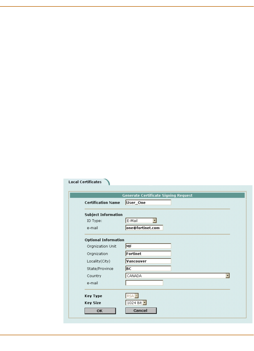
IPSec VPN Managing digital certificates
FortiWiFi-60 Installation and Configuration Guide 213
6Configure the key.
7Select OK to generate the private and public key pair and the certificate request.
The private/public key pair are generated and the certificate request is displayed on
the Local Certificates list with a status of Pending.
Figure 24: Adding a Local Certificate
Organization Unit Enter a name that identifies the department or unit within the organization
that is requesting the certificate for the FortiWiFi unit (such as
Manufacturing or MF).
Organization Enter the legal name of the organization that is requesting the certificate
for the FortiWiFi unit (such as Fortinet).
Locality Enter the name of the city or town where the FortiWiFi unit is located
(such as Vancouver).
State/Province Enter the name of the state or province where the FortiWiFi unit is located
(such as California or CA).
Country Select the country where the FortiWiFi unit is located.
e-mail Enter a contact email address for the FortiWiFi unit. Typically, email
addresses are entered only for clients, not gateways.
Key Type Select RSA as the key encryption type. No other key type is supported.
Key Size Select 1024 Bit, 1536 Bit or 2048 Bit. Larger keys are slower to generate
but more secure. Not all IPSec VPN products support all three key sizes.

214 Fortinet Inc.
Managing digital certificates IPSec VPN
Downloading the certificate request
Use the following procedure to download a certificate request from the FortiWiFi unit
to the management computer.
To download the certificate request
1Go to VPN > Certificates > Local Certificates.
2Select Download to download the local certificate to the management computer.
3Select Save.
4Name the file and save it in a directory on the management computer.
After downloading the certificate request, you can submit it tor your CA so that your
CA can sign the certificate.
Importing the signed local certificate
With this procedure, you import the signed local certificate from the management
computer to the FortiWiFi unit.
To import the signed local certificate
1Go to VPN > Certificates > Local Certificates.
2Select Import.
3Enter the path or browse to locate the signed local certificate on the management
computer.
4Select OK.
The signed local certificate is displayed on the Local Certificates list with a status of
OK.
Backing up and restoring the local certificate and private key
When you back up a FortiWiFi configuration that includes IPSec VPN tunnels using
certificates, you must also back up the local certificate and private key in a password-
protected PKCS12 file. Before restoring the configuration, you must import the
PKCS12 file and set the local certificate name to the same that was in the original
configuration.
Public Key Cryptography Standard 12 (PKCS12) describes the syntax for securely
exchanging personal information.
Obtaining CA certificates
For the VPN peers to authenticate themselves to each other, they must both obtain a
CA certificate from the same certificate authority. The CA certificate provides the VPN
peers with a means to validate the digital certificates that they receive from other
devices.
Note: Use the execute vpn certificates key CLI command to back up and restore the
local certificate and private key. For more information, see the FortiGate CLI Reference Guide.

IPSec VPN Configuring encrypt policies
FortiWiFi-60 Installation and Configuration Guide 215
The FortiWiFi unit obtains the CA certificate to validate the digital certificate that it
receives from the remote VPN peer. The remote VPN peer obtains the CA certificate
to validate the digital certificate that it receives from the FortiWiFi unit.
Importing CA certificates
Import the CA certificate from the management computer to the FortiWiFi unit.
To import the CA certificate
1Go to VPN > Certificates > CA Certificates.
2Select Import.
3Enter the path or browse to locate the CA certificate on the management computer.
4Select OK.
The CA is displayed on the CA Certificates list.
The system assigns a unique name to each CA certificate. The names are numbered
consecutively (CA_Cert_1, CA_Cert_2, CA_Cert_3, and so on).
Configuring encrypt policies
A VPN connects the local, internal network to a remote, external network. The
principal role of the encrypt policy is to define (and limit) which addresses on these
networks can use the VPN.
A VPN requires only one encrypt policy to control both inbound and outbound
connections. Depending on how you configure it, the policy controls whether users on
your internal network can establish a tunnel to the remote network (the outbound
connection), and whether users on the remote network can establish a tunnel to your
internal network (the inbound connection). This flexibility allows one encrypt policy to
do the same function as two regular firewall policies.
Although the encrypt policy controls both incoming and outgoing connections, it must
always be configured as an outgoing policy. An outgoing policy has a source address
on an internal network and a destination address on an external network. The source
address identifies the addresses on the internal network that are part of the VPN. The
destination address identifies the addresses on the remote network that are part of the
VPN.
Note: The CA certificate must adhere to the X.509 standard.
Note: The destination address can be a VPN client address on the Internet or the address of a
network behind a remote VPN gateway.

216 Fortinet Inc.
Configuring encrypt policies IPSec VPN
In addition to defining membership in the VPN by address, you can configure the
encrypt policy for services such as DNS, FTP, and POP3, and to allow connections
according to a predefined schedule (by the time of the day or the day of the week,
month, or year). You can also configure the encrypt policy for:
• Inbound NAT to translate the source of incoming packets.
• Outbound NAT to translate the source address of outgoing packets.
• Traffic shaping to control the bandwidth available to the VPN and the priority of the
VPN.
• Content profiles to apply antivirus protection, web filtering, and email filtering to
web, file transfer, and email services in the VPN.
• Logging so that the FortiWiFi unit logs all connections that use the VPN.
The policy must also include the VPN tunnel that you created to communicate with the
remote FortiWiFi VPN gateway. When users on your internal network attempt to
connect to the network behind the remote VPN gateway, the encrypt policy intercepts
the connection attempt and starts the VPN tunnel added to the policy. The tunnel uses
the remote gateway added to its configuration to connect to the remote VPN gateway.
When the remote VPN gateway receives the connection attempt, it checks its own
policy, gateway, and tunnel configuration. If the configuration is allowed, an IPSec
VPN tunnel is negotiated between the two VPN peers.
•Adding a source address
•Adding a destination address
•Adding an encrypt policy
Adding a source address
The source address is located within the internal network of the local VPN peer. It can
be a single computer address or the address of a network.
To add a source address
1Go to Firewall > Address.
2Select an internal interface.
3Select New to add an address.
4Enter the Address Name, IP Address, and NetMask for a single computer or for an
entire subnetwork on an internal interface of the local VPN peer.
5Select OK to save the source address.
Adding a destination address
The destination address can be a VPN client address on the Internet or the address of
a network behind a remote VPN gateway.
To add a destination address
1Go to Firewall > Address.
2Select an external interface.
3Select New to add an address.

IPSec VPN Configuring encrypt policies
FortiWiFi-60 Installation and Configuration Guide 217
4Enter the Address Name, IP Address, and NetMask for a single computer or for an
entire subnetwork on an internal interface of the remote VPN peer.
5Select OK to save the destination address.
Adding an encrypt policy
To add an encrypt policy
1Go to Firewall > Policy.
2Select New to add a new policy.
3Set Source to the source address.
4Set Destination to the destination address.
5Set Service to control the services allowed over the VPN connection.
You can select ANY to allow all supported services over the VPN connection or select
a specific service or service group to limit the services allowed over the VPN
connection.
6Set Action to ENCRYPT.
7Configure the ENCRYPT parameters.
For information about configuring the remaining policy settings, see “Adding firewall
policies” on page 162.
8Select OK to save the encrypt policy.
To make sure that the encrypt policy is matched for VPN connections, arrange the
encrypt policy above other policies with similar source and destination addresses and
services in the policy list.
VPN Tunnel Select an Auto Key tunnel for this encrypt policy.
Allow inbound Select Allow inbound to enable inbound users to connect to the source
address.
Allow outbound Select Allow outbound to enable outbound users to connect to the
destination address.
Inbound NAT The FortiWiFi unit translates the source address of incoming packets to the
IP address of the FortiWiFi interface connected to the source address
network. Typically, this is an internal interface of the FortiWiFi unit.
Inbound NAT makes it impossible for local hosts to see the IP addresses of
remote hosts (hosts located on the network behind the remote VPN
gateway).
Outbound NAT The FortiWiFi unit translates the source address of outgoing packets to the
IP address of the FortiWiFi interface connected to the destination address
network. Typically, this is an external interface of the FortiWiFi unit.
Outbound NAT makes it impossible for remote hosts to see the IP
addresses of local hosts (hosts located on the network behind the local VPN
gateway).
If Outbound NAT is implemented, it is subject to these limitations:
Configure Outbound NAT only at one end of the tunnel.
The end that does not implement Outbound NAT requires an internal to
external policy that specifies the remote external interface as the
Destination (usually a public IP address).
The tunnel, and the traffic within the tunnel, can only be initiated at the end
that implements Outbound NAT.
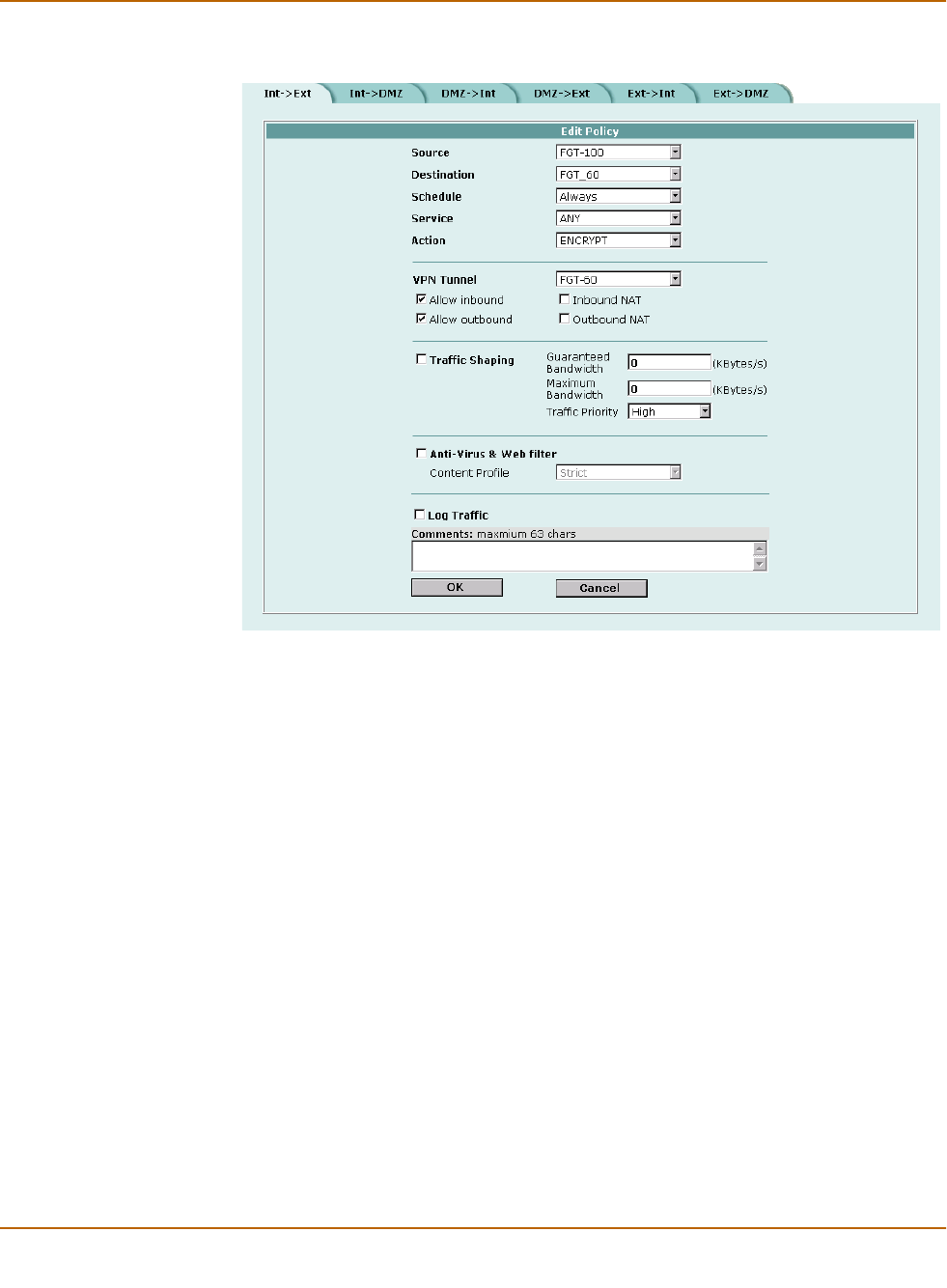
218 Fortinet Inc.
IPSec VPN concentrators IPSec VPN
Figure 25: Adding an encrypt policy
IPSec VPN concentrators
In a hub-and-spoke network, all VPN tunnels terminate at a single VPN peer called a
hub. The peers that connect to the hub are known as spokes. The hub functions as a
concentrator on the network, managing the VPN connections between the spokes.
The advantage of a hub-and-spoke network is that the spokes are simpler to configure
because they require fewer policy rules. Also, a hub-and-spoke network provides
some processing efficiencies, particularly on the spokes. The disadvantage of a hub-
and-spoke network is its reliance on a single peer to handle management of all VPNs.
If this peer fails, encrypted communication in the network is impossible.
A hub-and-spoke VPN network requires a special configuration. Setup varies
depending on the role of the VPN peer.
If the VPN peer is a FortiWiFi unit functioning as the hub, or concentrator, it requires a
VPN configuration connecting it to each spoke (AutoIKE phase 1 and 2 settings or
manual key settings, plus encrypt policies). It also requires a concentrator
configuration that groups the hub-and-spoke tunnels together. The concentrator
configuration defines the FortiWiFi unit as the hub in a hub-and-spoke network.

IPSec VPN IPSec VPN concentrators
FortiWiFi-60 Installation and Configuration Guide 219
If the VPN peer is one of the spokes, it requires a tunnel connecting it to the hub (but
not to the other spokes). It also requires policies that control its encrypted connections
to the other spokes and its non-encrypted connections to other networks, such as the
Internet.
•VPN concentrator (hub) general configuration steps
•Adding a VPN concentrator
•VPN spoke general configuration steps
VPN concentrator (hub) general configuration steps
A central FortiWiFi that is functioning as a hub requires the following configuration:
• A tunnel (AutoIKE phase 1 and phase 2 configuration or manual key configuration)
for each spoke.
• Destination addresses for each spoke.
• A concentrator configuration.
• An encrypt policy for each spoke.
To create a VPN concentrator configuration
1Configure one of the following tunnels for each spoke:
• A manual key tunnel consists of a name for the tunnel, the IP address of the spoke
(client or gateway) at the opposite end of the tunnel, and the encryption and
authentication algorithms to use for the tunnel.
See “Manual key IPSec VPNs” on page 203.
• An AutoIKE tunnel consists of phase 1 and phase 2 parameters. The phase 1
parameters include the name of the spoke (client or gateway), designation of how
the spoke receives its IP address (static or dialup), encryption and authentication
algorithms, and the authentication method (either pre-shared keys or PKI
certificates). The phase 2 parameters include the name of the tunnel, selection of
the spoke (client or gateway) configured in phase 1, encryption and authentication
algorithms, and a number of security parameters.
See “AutoIKE IPSec VPNs” on page 205.
2Add a destination address for each spoke. The destination address is the address of
the spoke (either a client on the Internet or a network located behind a gateway).
See “Adding a source address” on page 216.
3Add the concentrator configuration. This step groups the tunnels together on the
FortiWiFi unit. The tunnels link the hub to the spokes. The tunnels are added as part
of the AutoIKE phase 2 configuration or the manual key configuration.
See “Adding a VPN concentrator” on page 220.
4Add an encrypt policy for each spoke. Encrypt policies control the direction of traffic
through the hub and allow inbound and outbound VPN connections between the hub
and the spokes. The encrypt policy for each spoke must include the tunnel name of
the spoke. The source address must be Internal_All. Use the following configuration
for the encrypt policies:
Note: Add the concentrator configuration to the central FortiWiFi unit (the hub) after adding the
tunnels for all spokes.

220 Fortinet Inc.
IPSec VPN concentrators IPSec VPN
See “Adding an encrypt policy” on page 217.
5Arrange the policies in the following order:
• encrypt policies
• default non-encrypt policy (Internal_All -> External_All)
Adding a VPN concentrator
To add a VPN concentrator configuration
1Go to VPN > IPSec > Concentrator.
2Select New to add a VPN concentrator.
3Enter the name of the new concentrator in the Concentrator Name field.
4To add tunnels to the VPN concentrator, select a VPN tunnel from the Available
Tunnels list and select the right arrow.
5To remove tunnels from the VPN concentrator, select the tunnel in the Members list
and select the left arrow.
6Select OK to add the VPN concentrator.
Source Internal_All
Destination The VPN spoke address.
Action ENCRYPT
VPN Tunnel The VPN spoke tunnel name.
Allow inbound Select allow inbound.
Allow outbound Select allow outbound
Inbound NAT Select inbound NAT if required.
Outbound NAT Select outbound NAT if required.
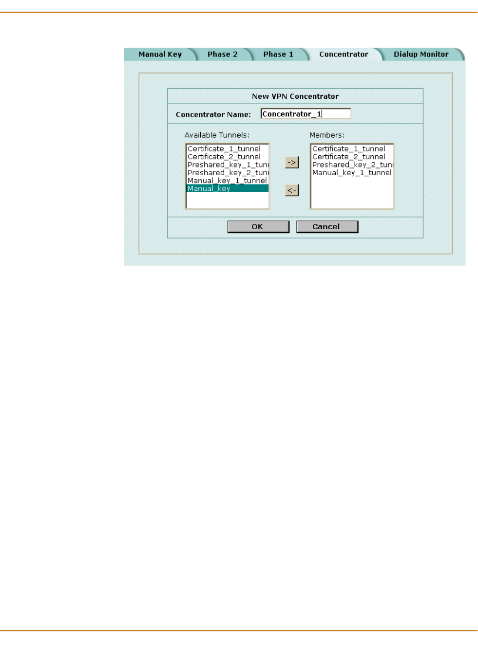
IPSec VPN IPSec VPN concentrators
FortiWiFi-60 Installation and Configuration Guide 221
Figure 26: Adding a VPN concentrator
VPN spoke general configuration steps
A remote VPN peer that functions as a spoke requires the following configuration:
• A tunnel (AutoIKE phase 1 and phase 2 configuration or manual key configuration)
for the hub.
• The source address of the local VPN spoke.
• The destination address of each remote VPN spoke.
• A separate outbound encrypt policy for each remote VPN spoke. These policies
allow the local VPN spoke to initiate encrypted connections.
• A single inbound encrypt policy. This policy allows the local VPN spoke to accept
encrypted connections.
To create a VPN spoke configuration
1Configure a tunnel between the spoke and the hub.
Choose between a manual key tunnel or an AutoIKE tunnel.
• To add a manual key tunnel, see “Manual key IPSec VPNs” on page 203.
• To add an AutoIKE tunnel, see “AutoIKE IPSec VPNs” on page 205.
2Add the source address. One source address is required for the local VPN spoke.
See “Adding a source address” on page 216.
3Add a destination address for each remote VPN spoke. The destination address is the
address of the spoke (either a client on the Internet or a network located behind a
gateway).
See “Adding a destination address” on page 216

222 Fortinet Inc.
IPSec VPN concentrators IPSec VPN
4Add a separate outbound encrypt policy for each remote VPN spoke. These policies
control the encrypted connections initiated by the local VPN spoke.
The encrypt policy must include the appropriate source and destination addresses
and the tunnel added in step 1. Use the following configuration:
See “Adding an encrypt policy” on page 217.
5Add an inbound encrypt policy. This policy controls the encrypted connections initiated
by the remote VPN spokes.
The encrypt policy for the hub must include the appropriate source and destination
addresses and the tunnel added in step 1. Use the following configuration:
See “Adding an encrypt policy” on page 217.
6Arrange the policies in the following order:
• outbound encrypt policies
• inbound encrypt policy
• default non-encrypt policy (Internal_All -> External_All)
Source The local VPN spoke address.
Destination The remote VPN spoke address.
Action ENCRYPT
VPN Tunnel The VPN tunnel name added in step 1. (Use the same tunnel for all encrypt
policies.)
Allow inbound Do not enable.
Allow outbound Select allow outbound
Inbound NAT Select inbound NAT if required.
Outbound NAT Select outbound NAT if required.
Source The local VPN spoke address.
Destination External_All
Action ENCRYPT
VPN Tunnel The VPN tunnel name added in step 1. (Use the same tunnel for all encrypt
policies.)
Allow inbound Select allow inbound.
Allow outbound Do not enable.
Inbound NAT Select inbound NAT if required.
Outbound NAT Select outbound NAT if required.
Note: The default non-encrypt policy is required to allow the VPN spoke to access other
networks, such as the Internet.
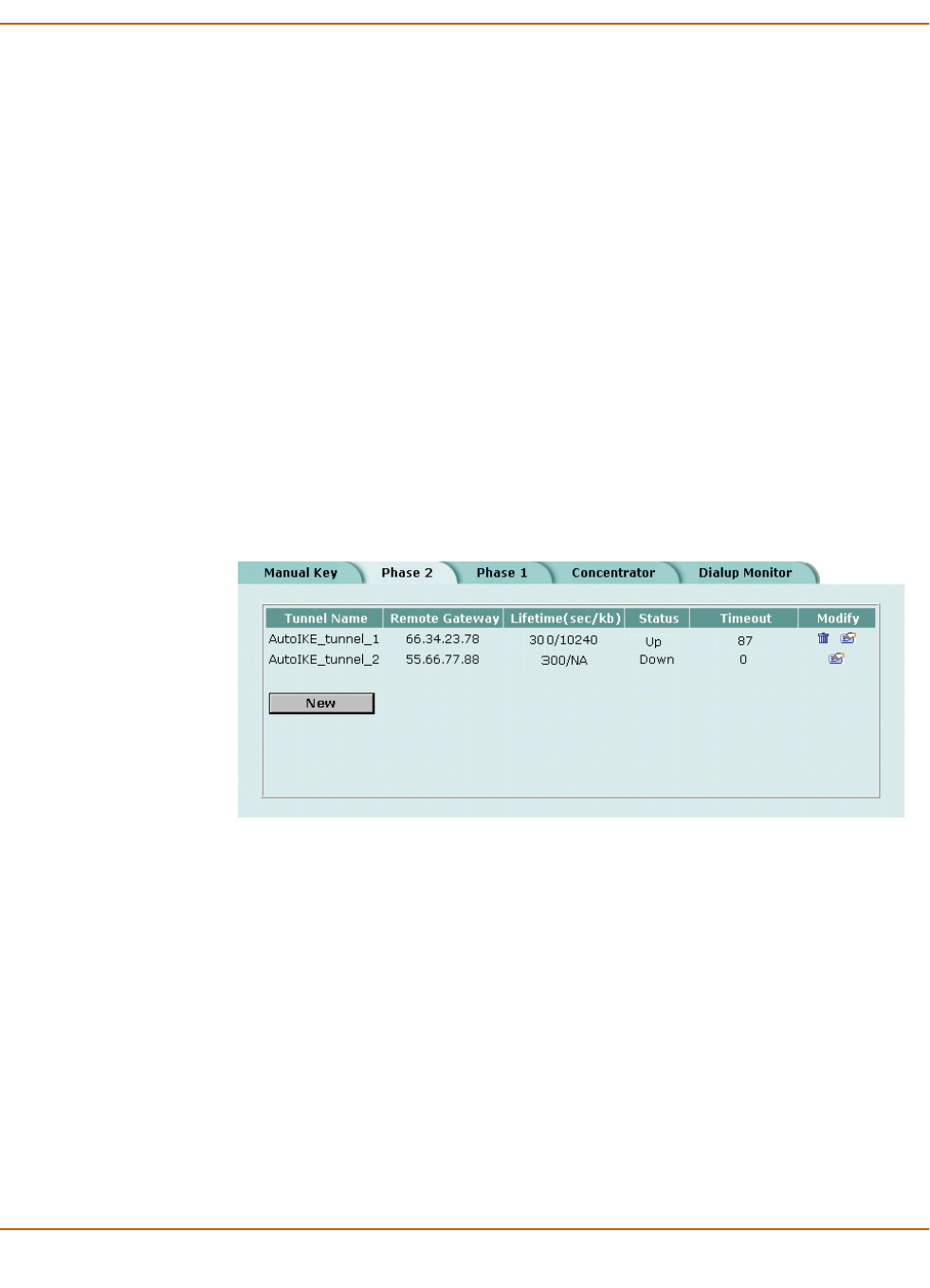
IPSec VPN Monitoring and Troubleshooting VPNs
FortiWiFi-60 Installation and Configuration Guide 223
Monitoring and Troubleshooting VPNs
•Viewing VPN tunnel status
•Viewing dialup VPN connection status
•Testing a VPN
Viewing VPN tunnel status
You can use the IPSec VPN tunnel list to view the status of all IPSec AutoIKE key
VPN tunnels. For each tunnel, the list shows the status and the tunnel time out.
To view VPN tunnel status
1Go to VPN > IPSEC > Phase 2.
2View the status and timeout for each VPN tunnel.
Figure 27: AutoIKE key tunnel status
Viewing dialup VPN connection status
You can use the dialup monitor to view the status of dialup VPNs. The dialup monitor
lists the remote gateways and the active VPN tunnels for each gateway. The monitor
also lists the tunnel lifetime, timeout, proxy ID source, and proxy ID destination for
each tunnel.
To view dialup connection status
1Go to VPN > IPSec > Dialup Monitor.
2View the dialup connection status information for the FortiWiFi unit:
Status The status of each tunnel. If Status is Up, the tunnel is active. If Status is
Down, the tunnel is not active. If Status is Connecting, the tunnel is
attempting to start a VPN connection with a remote VPN gateway or client.
Timeout The time before the next key exchange. The time is calculated by
subtracting the time elapsed since the last key exchange from the keylife.
Remote gateway The IP address of the remote dialup remote gateway on the FortiWiFi unit.
Lifetime The amount of time that the dialup VPN connection has been active.
Timeout The time before the next key exchange. The time is calculated by
subtracting the time elapsed since the last key exchange from the keylife.
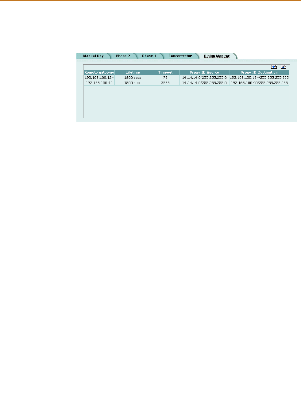
224 Fortinet Inc.
Monitoring and Troubleshooting VPNs IPSec VPN
Figure 28: Dialup Monitor
Testing a VPN
To confirm that a VPN between two networks has been configured correctly, use the
ping command from one internal network to connect to a computer on the other
internal network. The IPSec VPN tunnel starts automatically when the first data packet
destined for the VPN is intercepted by the FortiWiFi unit.
To confirm that a VPN between a network and one or more clients has been
configured correctly, start a VPN client and use the ping command to connect to a
computer on the internal network. The VPN tunnel initializes automatically when the
client makes a connection attempt. You can start the tunnel and test it at the same
time by pinging from the client to an address on the internal network.
Proxy ID Source The actual IP address or subnet address of the remote peer.
Proxy ID
Destination
The actual IP address or subnet address of the local peer.

FortiWiFi-60 Installation and Configuration Guide Version 2.50
FortiWiFi-60 Installation and Configuration Guide 225
PPTP and L2TP VPN
You can use PPTP and L2TP to create a virtual private network (VPN) between a
remote client computer that is running Windows and your internal network. Because
PPTP and L2TP are supported by Windows you do not require third-party software on
the client computer. Provided your ISP supports PPTP and L2TP connections, you
can create a secure connection by making some configuration changes to the client
computer and the FortiWiFi unit.
This chapter provides an overview of how to configure FortiWiFi PPTP and L2TP
VPN. For a complete description of FortiWiFi PPTP and L2TP, see the FortiGate VPN
Guide.
This chapter describes:
•Configuring PPTP
•Configuring L2TP
Configuring PPTP
Point-to-Point protocol (PPTP) packages data within PPP packets and then
encapsulates the PPP packets within IP packets for transmission through a VPN
tunnel.
This section describes:
•Configuring the FortiWiFi unit as a PPTP gateway
•Configuring a Windows 98 client for PPTP
•Configuring a Windows 2000 client for PPTP
•Configuring a Windows XP client for PPTP
Configuring the FortiWiFi unit as a PPTP gateway
Use the following procedures to configure the FortiWiFi unit as a PPTP gateway:
To add users and user groups
Add a user for each PPTP client.
1Go to User > Local.
Note: PPTP VPNs are supported only in NAT/Route mode.
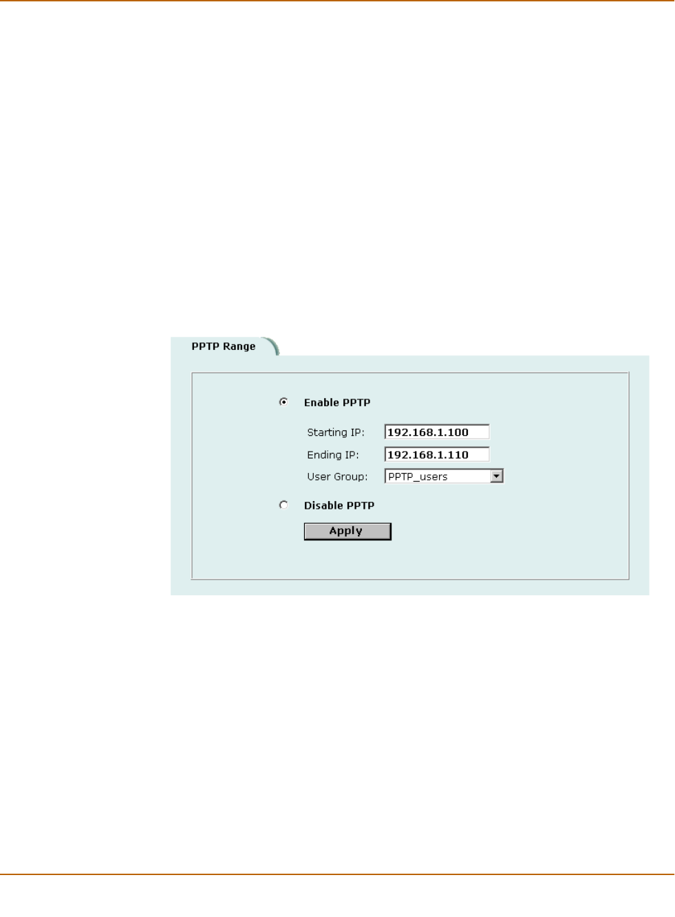
226 Fortinet Inc.
Configuring PPTP PPTP and L2TP VPN
2Add and configure PPTP users.
For information about adding and configuring users, see “Adding user names and
configuring authentication” on page 194.
3Go to User > User Group.
4Add and configure PPTP user groups.
For information about adding and configuring user groups, see “Configuring user
groups” on page 199.
To enable PPTP and specify an address range
1Go to VPN > PPTP > PPTP Range.
2Select Enable PPTP.
3Enter the Starting IP and the Ending IP for the PPTP address range.
4Select the User Group that you added in “To add users and user groups” on page 225.
5Select Apply to enable PPTP through the FortiWiFi unit.
Figure 29: Example PPTP Range configuration
To add a source address
Add a source address for every address in the PPTP address range.
1Go to Firewall > Address.
2Select the interface to which PPTP clients connect.
3Select New to add an address.
4Enter the Address Name, IP Address, and NetMask for an address in the PPTP
address range.
5Select OK to save the source address.
6Repeat for all addresses in the PPTP address range.

PPTP and L2TP VPN Configuring PPTP
FortiWiFi-60 Installation and Configuration Guide 227
To add a source address group
Organize the source addresses into an address group.
1Go to Firewall > Address > Group.
2Add a new address group to the interface to which PPTP clients connect.
3Enter a Group Name to identify the address group.
The name can contain numbers (0-9), uppercase and lowercase letters (A-Z, a-z), and
the special characters - and _. Other special characters and spaces are not allowed.
4To add addresses to the address group, select an address from the Available
Addresses list and select the right arrow to add it to the Members list.
5To remove addresses from the address group, select an address from the Members
list and select the left arrow to remove it from the group.
6Select OK to add the address group.
To add a destination address
Add an address to which PPTP users can connect.
1Go to Firewall > Address.
2Select the internal interface or the DMZ interface.
3Select New to add an address.
4Enter the Address Name, IP Address, and NetMask for a single computer or for an
entire subnetwork on an internal interface of the local VPN peer.
5Select OK to save the destination address.
To add a firewall policy
Add a policy which specifies the source and destination addresses and sets the
service for the policy to the traffic type inside the PPTP VPN tunnel.
1Go to Firewall > Policy.
2Select New to add a new policy.
3Set Source to the group that matches the PPTP address range.
4Set Destination to the address to which PPTP users can connect.
5Set Service to match the traffic type inside the PPTP VPN tunnel.
For example, if PPTP users can access a web server, select HTTP.
6Set Action to ACCEPT.
7Select NAT if address translation is required.
You can also configure traffic shaping, logging, and antivirus and web filter settings for
PPTP policies.
8Select OK to save the firewall policy.
Note: If the PPTP address range is comprised of an entire subnet, add an address for this
subnet. Do not add an address group.

228 Fortinet Inc.
Configuring PPTP PPTP and L2TP VPN
Configuring a Windows 98 client for PPTP
Use the following procedure to configure a client computer running Windows 98 so
that it can connect to a FortiWiFi PPTP VPN. To configure the Windows 98 client, you
must install and configure Windows dialup networking and virtual private networking
support.
To install PPTP support
1Go to Start > Settings > Control Panel > Network.
2Select Add.
3Select Adapter.
4Select Add.
5Select Microsoft as the manufacturer.
6Select Microsoft Virtual Private Networking Adapter.
7Select OK twice.
8Insert diskettes or CDs as required.
9Restart the computer.
To configure a PPTP dialup connection
1Go to My Computer > Dial-Up Networking > Configuration.
2Double-click Make New Connection.
3Name the connection and select Next.
4Enter the IP address or host name of the FortiWiFi unit to connect to and select Next.
5Select Finish.
An icon for the new connection appears in the Dial-Up Networking folder.
6Right-click the new icon and select Properties.
7Go to Server Types.
8Uncheck IPX/SPX Compatible.
9Select TCP/IP Settings.
10 Uncheck Use IP header compression.
11 Uncheck Use default gateway on remote network.
12 Select OK twice.
To connect to the PPTP VPN
1Start the dialup connection that you configured in the previous procedure.
2Enter your PPTP VPN User Name and Password.
3Select Connect.

PPTP and L2TP VPN Configuring PPTP
FortiWiFi-60 Installation and Configuration Guide 229
Configuring a Windows 2000 client for PPTP
Use the following procedure to configure a client computer running Windows 2000 so
that it can connect to a FortiWiFi PPTP VPN.
To configure a PPTP dialup connection
1Go to Start > Settings > Network and Dial-up Connections.
2Double-click Make New Connection to start the Network Connection Wizard and
select Next.
3For Network Connection Type, select Connect to a private network through the
Internet and select Next.
4For Destination Address, enter the IP address or host name of the FortiWiFi unit to
connect to and select Next.
5Set Connection Availability to Only for myself and select Next.
6Select Finish.
7In the Connect window, select Properties.
8Select the Security tab.
9Uncheck Require data encryption.
10 Select OK.
To connect to the PPTP VPN
1Start the dialup connection that you configured in the previous procedure.
2Enter your PPTP VPN User Name and Password.
3Select Connect.
4In the connect window, enter the User Name and Password that you use to connect to
your dialup network connection.
This user name and password is not the same as your VPN user name and password.
Configuring a Windows XP client for PPTP
Use the following procedure to configure a client computer running Windows XP so
that it can connect to a FortiWiFi PPTP VPN.
To configure a PPTP dialup connection
1Go to Start > Settings > Control Panel.
2Select Network and Internet Connections.
3Select Create a Connection to the network of your workplace and select Next.
4Select Virtual Private Network Connection and select Next.
5Name the connection and select Next.
6If the Public Network dialog box appears, choose the appropriate initial connection
and select Next.
7In the VPN Server Selection dialog, enter the IP address or host name of the FortiWiFi
unit to connect to and select Next.

230 Fortinet Inc.
Configuring PPTP PPTP and L2TP VPN
8Select Finish.
To configure the VPN connection
1Right-click the Connection icon that you created in the previous procedure.
2Select Properties > Security.
3Select Typical to configure typical settings.
4Select Require data encryption.
5Select Advanced to configure advanced settings.
6Select Settings.
7Select Challenge Handshake Authentication Protocol (CHAP).
8Make sure that none of the other settings are selected.
9Select the Networking tab.
10 Make sure that the following options are selected:
•TCP/IP
• QoS Packet Scheduler
11 Make sure that the following options are not selected:
• File and Printer Sharing for Microsoft Networks
• Client for Microsoft Networks
12 Select OK.
To connect to the PPTP VPN
1Connect to your ISP.
2Start the VPN connection that you configured in the previous procedure.
3Enter your PPTP VPN User Name and Password.
4Select Connect.
5In the connect window, enter the User Name and Password that you use for your
dialup network connection.
This user name and password is not the same as your VPN user name and password.
Note: If a RADIUS server is used for authentication do not select Require data encryption.
PPTP encryption is not supported for RADIUS server authentication.

PPTP and L2TP VPN Configuring L2TP
FortiWiFi-60 Installation and Configuration Guide 231
Configuring L2TP
Some implementations of L2TP support elements of IPSec. These elements must be
disabled when L2TP is used with a FortiWiFi unit.
This section describes:
•Configuring the FortiWiFi unit as an L2TP gateway
•Configuring a Windows 2000 client for L2TP
•Configuring a Windows XP client for L2TP
Configuring the FortiWiFi unit as an L2TP gateway
Use the following procedures to configure the FortiWiFi unit as an L2TP gateway:
To add users and user groups
Add a user for each L2TP client.
1Go to User > Local.
2Add and configure L2TP users.
See “Adding user names and configuring authentication” on page 194.
3Go to User > User Group.
4Add and configure L2TP user groups.
See “Configuring user groups” on page 199.
To enable L2TP and specify an address range
1Go to VPN > L2TP > L2TP Range.
2Select Enable L2TP.
3Enter the Starting IP and the Ending IP for the L2TP address range.
4Select the User Group that you added in “To add users and user groups” on page 231.
5Select Apply to enable L2TP through the FortiWiFi unit.
Note: L2TP VPNs are only supported in NAT/Route mode.
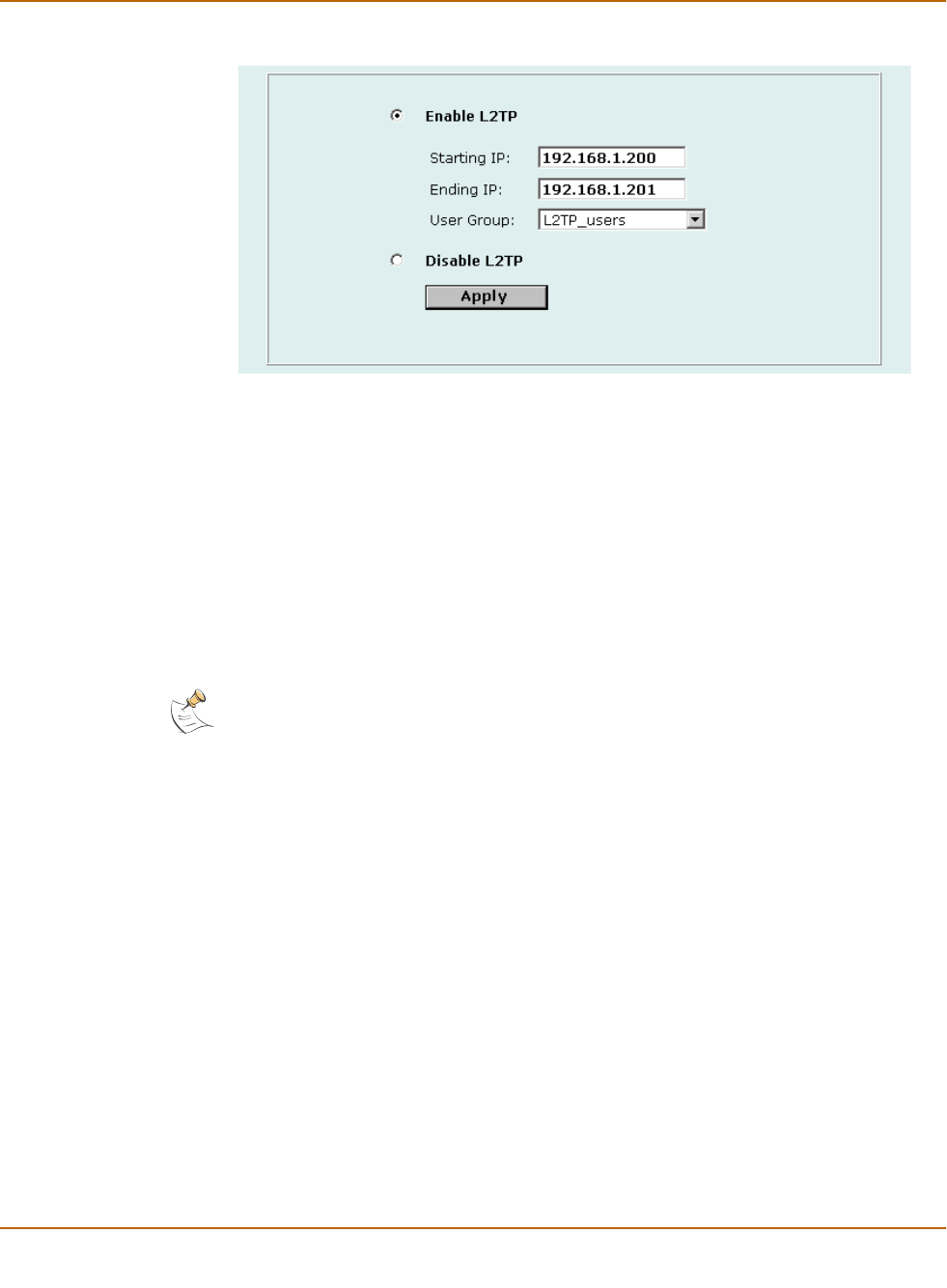
232 Fortinet Inc.
Configuring L2TP PPTP and L2TP VPN
Figure 30: Sample L2TP address range configuration
To add source addresses
Add a source address for every address in the L2TP address range.
1Go to Firewall > Address.
2Select the interface to which L2TP clients connect.
3Select New to add an address.
1Enter the Address Name, IP Address, and NetMask for an address in the L2TP
address range.
2Select OK to save the source address.
3Repeat for all addresses in the L2TP address range.
To add a source address group
Organize the source addresses into an address group.
1Go to Firewall > Address > Group.
2Add a new address group to the interface to which L2TP clients connect.
3Enter a Group Name to identify the address group.
The name can contain numbers (0-9), uppercase and lowercase letters (A-Z, a-z), and
the special characters - and _. Other special characters and spaces are not allowed.
4To add addresses to the address group, select an address from the Available
Addresses list and select the right arrow to add it to the Members list.
5To remove addresses from the address group, select an address from the Members
list and select the left arrow to remove it from the group.
6Select OK to add the address group.
To add a destination address
Note: If the L2TP address range is comprised of an entire subnet, add an address for this
subnet. Do not add an address group.

PPTP and L2TP VPN Configuring L2TP
FortiWiFi-60 Installation and Configuration Guide 233
Add an address to which L2TP users can connect.
1Go to Firewall > Address.
2Select the internal interface or the DMZ interface.
3Select New to add an address.
4Enter the Address Name, IP Address, and NetMask for a single computer or for an
entire subnetwork on an internal interface of the local VPN peer.
5Select OK to save the source address.
To add a firewall policy
Add a policy that specifies the source and destination addresses and sets the service
for the policy to the traffic type inside the L2TP VPN tunnel.
1Go to Firewall > Policy.
2Select New to add a policy.
3Set Source to the group that matches the L2TP address range.
4Set Destination to the address to which L2TP users can connect.
5Set Service to match the traffic type inside the L2TP VPN tunnel.
For example, if L2TP users can access a web server, select HTTP.
6Set Action to ACCEPT.
7Select NAT if address translation is required.
You can also configure traffic shaping, logging, and antivirus and web filter settings for
L2TP policies.
8Select OK to save the firewall policy.
Configuring a Windows 2000 client for L2TP
Use the following procedure to configure a client computer running Windows 2000 so
that it can connect to a FortiWiFi L2TP VPN.
To configure an L2TP dialup connection
1Go to Start > Settings > Network and Dial-up Connections.
2Double-click Make New Connection to start the Network Connection Wizard and
select Next.
3For Network Connection Type, select Connect to a private network through the
Internet and select Next.
4For Destination Address, enter the address of the FortiWiFi unit to connect to and
select Next.
5Set Connection Availability to Only for myself and select Next.
6Select Finish.
7In the Connect window, select Properties.
8Select the Security tab.
9Make sure that Require data encryption is selected.

234 Fortinet Inc.
Configuring L2TP PPTP and L2TP VPN
10 Select the Networking tab.
11 Set VPN server type to Layer-2 Tunneling Protocol (L2TP).
12 Save the changes and continue with the following procedure.
To disable IPSec
1Select the Networking tab.
2Select Internet Protocol (TCP/IP) properties.
3Double-click the Advanced tab.
4Go to the Options tab and select IP security properties.
5Make sure that Do not use IPSEC is selected.
6Select OK and close the connection properties window.
7Use the registry editor (regedit) to locate the following key in the registry:
HKEY_LOCAL_MACHINE\System\CurrentControlSet\Services\Rasman\
Parameters
8Add the following registry value to this key:
Value Name: ProhibitIpSec
Data Type: REG_DWORD
Value: 1
9Save the changes and restart the computer for the changes to take effect.
You must add the ProhibitIpSec registry value to each Windows 2000-based
endpoint computer of an L2TP or IPSec connection to prevent the automatic filter for
L2TP and IPSec traffic from being created. When the ProhibitIpSec registry value
is set to 1, your Windows 2000-based computer does not create the automatic filter
that uses CA authentication. Instead, it checks for a local or active directory IPSec
policy.
To connect to the L2TP VPN
1Start the dialup connection that you configured in the previous procedure.
2Enter your L2TP VPN User Name and Password.
3Select Connect.
4In the connect window, enter the User Name and Password that you use to connect to
your dialup network connection.
This user name and password is not the same as your VPN user name and password.
Note: If a RADIUS server is used for authentication do not select Require data encryption.
L2TP encryption is not supported for RADIUS server authentication.
Note: The default Windows 2000 L2TP traffic policy does not allow L2TP traffic without IPSec
encryption. You can disable default behavior by editing the Windows 2000 Registry as
described in the following steps. See the Microsoft documentation for editing the Windows
Registry.

PPTP and L2TP VPN Configuring L2TP
FortiWiFi-60 Installation and Configuration Guide 235
Configuring a Windows XP client for L2TP
Use the following procedure to configure a client computer running Windows XP so
that it can connect to a FortiWiFi L2TP VPN.
To configure an L2TP VPN dialup connection
1Go to Start > Settings.
2Select Network and Internet Connections.
3Select Create a connection to the network of your workplace and select Next.
4Select Virtual Private Network Connection and select Next.
5Name the connection and select Next.
6If the Public Network dialog box appears, choose the appropriate initial connection
and select Next.
7In the VPN Server Selection dialog, enter the IP address or host name of the FortiWiFi
unit to connect to and select Next.
8Select Finish.
To configure the VPN connection
1Right-click the icon that you created.
2Select Properties > Security.
3Select Typical to configure typical settings.
4Select Require data encryption.
5Select Advanced to configure advanced settings.
6Select Settings.
7Select Challenge Handshake Authentication Protocol (CHAP).
8Make sure that none of the other settings are selected.
9Select the Networking tab.
10 Make sure that the following options are selected:
•TCP/IP
• QoS Packet Scheduler
11 Make sure that the following options are not selected:
• File and Printer Sharing for Microsoft Networks
• Client for Microsoft Networks
To disable IPSec
1Select the Networking tab.
2Select Internet Protocol (TCP/IP) properties.
3Double-click the Advanced tab.
Note: If a RADIUS server is used for authentication do not select Require data encryption.
L2TP encryption is not supported for RADIUS server authentication.

236 Fortinet Inc.
Configuring L2TP PPTP and L2TP VPN
4Go to the Options tab and select IP security properties.
5Make sure that Do not use IPSEC is selected.
6Select OK and close the connection properties window.
7Use the registry editor (regedit) to locate the following key in the registry:
HKEY_LOCAL_MACHINE\System\CurrentControlSet\Services\Rasman\
Parameters
8Add the following registry value to this key:
Value Name: ProhibitIpSec
Data Type: REG_DWORD
Value: 1
9Save the changes and restart the computer for the changes to take effect.
You must add the ProhibitIpSec registry value to each Windows XP-based
endpoint computer of an L2TP or IPSec connection to prevent the automatic filter for
L2TP and IPSec traffic from being created. When the ProhibitIpSec registry value
is set to 1, your Windows XP-based computer does not create the automatic filter that
uses CA authentication. Instead, it checks for a local or active directory IPSec policy.
To connect to the L2TP VPN
1Connect to your ISP.
2Start the VPN connection that you configured in the previous procedure.
3Enter your L2TP VPN User Name and Password.
4Select Connect.
5In the connect window, enter the User Name and Password that you use to connect to
your dialup network connection.
This user name and password is not the same as your VPN user name and password.
Note: The default Windows XP L2TP traffic policy does not allow L2TP traffic without IPSec
encryption. You can disable default behavior by editing the Windows XP Registry as described
in the following steps. See the Microsoft documentation for editing the Windows Registry.

FortiWiFi-60 Installation and Configuration Guide Version 2.50
FortiWiFi-60 Installation and Configuration Guide 237
Network Intrusion Detection System
(NIDS)
The FortiWiFi NIDS is a real-time network intrusion detection sensor that uses attack
signature definitions to both detect and prevent a wide variety of suspicious network
traffic and direct network-based attacks. Also, whenever an attack occurs, the
FortiWiFi NIDS can record the event in a log and send an alert email to the system
administrator.
This chapter describes:
•Detecting attacks
•Preventing attacks
•Logging attacks
Detecting attacks
The NIDS Detection module detects a wide variety of suspicious network traffic and
network-based attacks. Use the following procedures to configure the general NIDS
settings and the NIDS Detection module Signature List.
For the general NIDS settings, you must select which interfaces you want to be
monitored for network-based attacks. You also need to decide whether to enable
checksum verification. Checksum verification tests the integrity of packets received at
the monitored interfaces.
This section describes:
•Selecting the interfaces to monitor
•Disabling monitoring interfaces
•Configuring checksum verification
•Viewing the signature list
•Viewing attack descriptions
•Disabling NIDS attack signatures
•Adding user-defined signatures
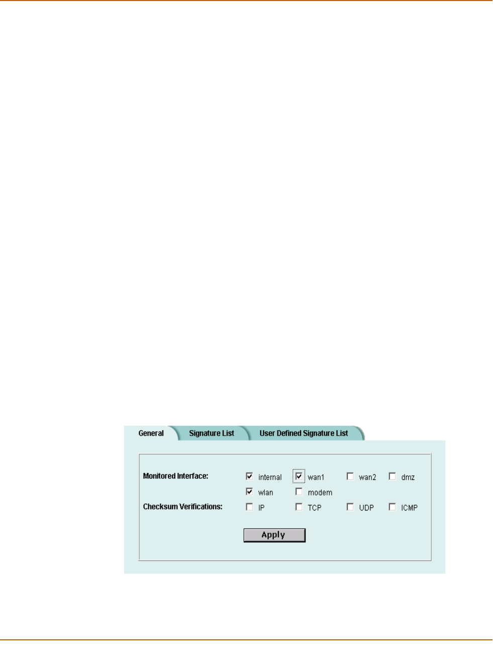
238 Fortinet Inc.
Detecting attacks Network Intrusion Detection System (NIDS)
Selecting the interfaces to monitor
To select the interfaces to monitor for attacks
1Go to NIDS > Detection > General.
2Select the interfaces to monitor for network attacks.
You can select one or more interfaces.
3Select Apply.
Disabling monitoring interfaces
To disable monitoring interfaces for attacks
1Go to NIDS > Detection > General.
2Clear the check box for all the interfaces that you do not want monitored.
3Select Apply.
Configuring checksum verification
Checksum verification tests the files that pass through the FortiWiFi unit to make sure
that they have not been changed in transit. The NIDS can run checksum verification
on IP, TCP, UDP, and ICMP traffic. For maximum detection, you can turn on checksum
verification for all types of traffic. However, if the FortiWiFi unit does not need to run
checksum verification, you can turn it off for some or all types of traffic to improve
system performance. For example, you might not need to run checksum verification if
the FortiWiFi unit is installed behind a router that also does checksum verification.
To configure checksum verification
1Go to NIDS > Detection > General.
2Select the type of traffic that you want to run Checksum Verifications on.
3Select Apply.
Figure 31: Example NIDS detection configuration

Network Intrusion Detection System (NIDS) Detecting attacks
FortiWiFi-60 Installation and Configuration Guide 239
Viewing the signature list
You can display the current list of NIDS signature groups and the members of a
signature group.
To view the signature list
1Go to NIDS > Detection > Signature List.
2View the names and action status of the signature groups in the list.
The NIDS detects attacks listed in all the signature groups that have check marks in
the Enable column.
3Select View Details .to display the members of a signature group.
The Signature Group Members list displays the attack ID, Rule Name, and Revision
number for each group member.
Viewing attack descriptions
Fortinet provides online information for all NIDS attacks. You can view the
FortiResponse Attack Analysis web page for an attack listed on the signature list.
To view attack descriptions
1Go to NIDS > Detection > Signature List.
2Select View Details .to display the members of a signature group.
3Select a signature and copy its attack ID.
4Open a web browser and enter the following URL:
http://www.fortinet.com/ids/ID<attack-ID>
Make sure that you include the attack ID.
For example, to view the Fortinet Attack Analysis web page for the ssh CRC32
overflow /bin/sh attack (ID 101646338), use the following URL:
http://www.fortinet.com/ids/ID101646338
Note: The user-defined signature group is the last item in the signature list. See “Adding user-
defined signatures” on page 240.
Note: Each attack log message includes a URL that links directly to the FortiResponse Attack
Analysis web page for that attack. This URL is available in the Attack Log messages and Alert
email messages. For information about log message content and formats, and about log
locations, see the FortiGate Logging and Message Reference Guide. For information about
logging attack messages, see “Logging attacks” on page 244.
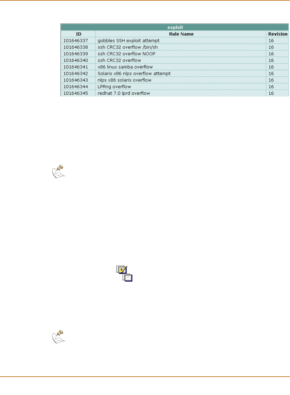
240 Fortinet Inc.
Detecting attacks Network Intrusion Detection System (NIDS)
Figure 32: Example signature group members list
Disabling NIDS attack signatures
By default, all NIDS attack signatures are enabled. You can use the NIDS signature
list to disable detection of some attacks. Disabling unnecessary NIDS attack
signatures can improve system performance and reduce the number of IDS log
messages and alert emails that the NIDS generates. For example, the NIDS detects a
large number of web server attacks. If you do not provide access to a web server
behind your firewall, you might want to disable all web server attack signatures.
To disable NIDS attack signatures
1Go to NIDS > Detection > Signature List.
2Scroll through the signature list to find the signature group that you want to disable.
Attack ID numbers and rule names in attack log messages and alert email match
those in the signature group members list. You can scroll through a signature group
members list to locate specific attack signatures by ID number and name.
3Clear the Enable check box.
4Select OK.
5Repeat steps 2 to 4 for each NIDS attack signature group that you want to disable.
Select Check All to enable all NIDS attack signature groups in the signature list.
Select Uncheck All to disable all NIDS attack signature groups in the signature
list.
Adding user-defined signatures
You can create a user-defined signature list in a text file and upload it from the
management computer to the FortiWiFi unit.
For information about how to write user-defined signatures, see the FortiGate NIDS
Guide.
Note: To save your NIDS attack signature settings, Fortinet recommends that you back up your
FortiWiFi configuration before you update the firmware and restore the saved configuration after
the update.
Note: You cannot upload individual signatures. You must include, in a single text file, all the
user-defined signatures that you want to upload. The file can contain one or more signatures.
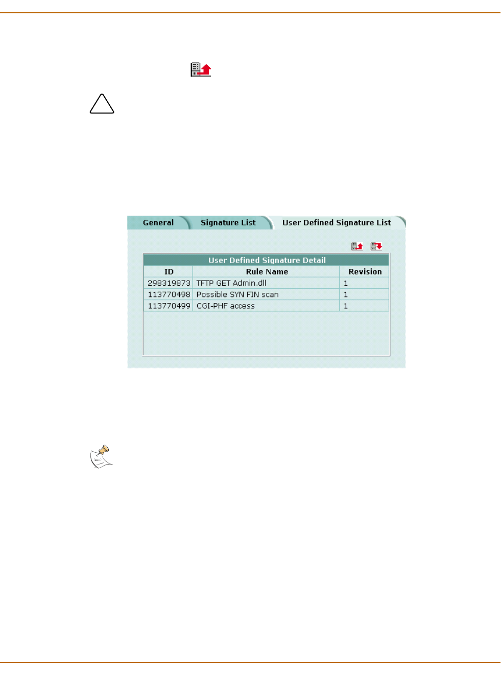
Network Intrusion Detection System (NIDS) Detecting attacks
FortiWiFi-60 Installation and Configuration Guide 241
To add user-defined signatures
1Go to NIDS > Detection > User Defined Signature List.
2Select Upload .
3Type the path and filename of the text file for the user-defined signature list or select
Browse and locate the file.
4Select OK to upload the text file for the user-defined signature list.
5Select Return to display the uploaded user-defined signature list.
Figure 33: Example user-defined signature list
Downloading the user-defined signature list
You can back up the user-defined signature list by downloading it to a text file on the
management computer.
To download the user-defined signature list
1Go to NIDS > Detection > User Defined Signature List.
2Select Download.
The FortiWiFi unit downloads the user-defined signature list to a text file on the
management computer. You can specify a location to which to download the text file
as well as a name for the text file.
!Caution: Uploading the user-defined signature list overwrites the existing file.
Note: You cannot download individual signatures. You must download the entire user-defined
signature list.
242 Fortinet Inc.
Preventing attacks Network Intrusion Detection System (NIDS)
Preventing attacks
NIDS attack prevention protects the FortiWiFi unit and the networks connected to it
from common TCP, ICMP, UDP, and IP attacks. You can enable NIDS attack
prevention to prevent a set of default attacks with default threshold values. You can
also enable or disable and set the threshold values for individual attack prevention
signatures.
•Enabling NIDS attack prevention
•Enabling NIDS attack prevention signatures
•Setting signature threshold values
Enabling NIDS attack prevention
To enable NIDS attack prevention
1Go to NIDS > Prevention.
2Select the Enable Prevention check box, in the top left corner.
Enabling NIDS attack prevention signatures
The NIDS Prevention module contains signatures that are designed to protect your
network against attacks. Some signatures are enabled by default, others must be
enabled. For a complete list of NIDS Prevention signatures and descriptions, see the
FortiGate NIDS Guide.
To enable attack prevention signatures
1Go to NIDS > Prevention.
2Select the Enable check box beside each signature that you want to enable.
3Select Check All to enable all signatures in the NIDS attack prevention signature
list.
4Select Uncheck All to disable all signatures in the NIDS attack prevention
signature list.
5Select Reset to Default Values to enable only the default NIDS attack prevention
signatures and return to the default threshold values.
Setting signature threshold values
You can change the default threshold values for the NIDS Prevention signatures listed
in Tab le 2 0 . The threshold depends on the type of attack. For flooding attacks, the
threshold is the maximum number of packets received per second. For overflow
attacks, the threshold is the buffer size for the command. For large ICMP attacks, the
threshold is the ICMP packet size limit to pass through.
Note: After the FortiWiFi unit reboots, NIDS attack prevention and synflood prevention are
always disabled.
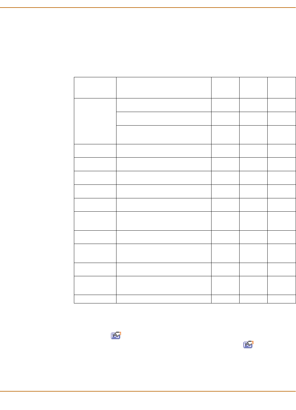
Network Intrusion Detection System (NIDS) Preventing attacks
FortiWiFi-60 Installation and Configuration Guide 243
For example, setting the icmpflood signature threshold to 500 allows 500 echo
requests from a source address, to which the system sends echo replies. The
FortiWiFi unit drops any requests over the threshold of 500.
If you enter a threshold value of 0 or a number out of the allowable range, the
FortiWiFi unit uses the default value.
To set Prevention signature threshold values
1Go to NIDS > Prevention.
2Select Modify beside the signature for which you want to set the Threshold value.
Signatures that do not have threshold values do not have Modify icons.
3Type the Threshold value.
4Select the Enable check box.
5Select OK.
Table 20: NIDS Prevention signatures with threshold values
Signature
abbreviation
Threshold value units Default
threshold
value
Minimum
threshold
value
Maximum
threshold
value
synflood Threshold: Maximum number of SYN
segments received per second.
2048 1 1000000
Queue Size: Maximum proxied
connections.
4096 100 1000000
Timeout: Number of seconds for the
SYN cookie to keep a proxied
connection alive.
15 1 3600
portscan Maximum number of SYN segments
received per second
512 1 1000000
srcsession Total number of TCP sessions initiated
from the same source
2048 1 1000000
ftpovfl Maximum buffer size for an FTP
command (bytes)
256 32 1408
smtpovfl Maximum buffer size for an SMTP
command (bytes)
512 32 1408
pop3ovfl Maximum buffer size for a POP3
command (bytes)
512 32 1408
udpflood Maximum number of UDP packets
received from the same source or sent
to the same destination per second
2048 1 1000000
udpsrcsession Total number of UDP sessions initiated
from the same source
2048 1 1000000
icmpflood Maximum number of ICMP packets
received from the same source or sent
to the same destination per second
256 1 1000000
icmpsrcsession Total number of ICMP sessions
initiated from the same source
128 1 1000000
icmpsweep Maximum number of ICMP packets
received from the same source per
second
128 1 1000000
icmplarge Maximum ICMP packet size (bytes) 32000 64 64000

244 Fortinet Inc.
Logging attacks Network Intrusion Detection System (NIDS)
Logging attacks
Whenever the NIDS detects or prevents an attack, it generates an attack message.
You can configure the system to add the message to the attack log.
•Logging attack messages to the attack log
•Reducing the number of NIDS attack log and email messages
Logging attack messages to the attack log
To log attack messages to the attack log
1Go to Log&Report > Log Setting.
2Select Config Policy for the log locations you have set.
3Select Attack Log.
4Select Attack Detection and Attack Prevention.
5Select OK.
Reducing the number of NIDS attack log and email messages
Intrusion attempts might generate an excessive number of attack messages. Based
on the frequency that messages are generated, the FortiWiFi unit automatically
deletes duplicates. If you still receive an excessive number of unnecessary
messages, you can manually disable message generation for unneeded signature
groups.
Automatic message reduction
The attack log and alert email messages that the NIDS produces include the ID
number and name of the attack that generated the message. The attack ID number
and name in the message are identical to the ID number and rule name that appear
on the NIDS Signature Group Members list.
The FortiWiFi unit uses an alert email queue in which each new message is compared
with the previous messages. If the new message is not a duplicate, the FortiWiFi unit
sends it immediately and puts a copy in the queue. If the new message is a duplicate,
the FortiWiFi unit deletes it and increases an internal counter for the number of
message copies in the queue.
The FortiWiFi unit holds duplicate alert email messages for 60 seconds. If a duplicate
message has been in the queue for more than 60 seconds, the FortiWiFi unit deletes
the message and increases the copy number. If the copy number is greater than 1, the
FortiWiFi unit sends a summary email that includes “Repeated x times” in the subject
header, the statement “The following email has been repeated x times in the last y
seconds”, and the original message.
Note: For information about log message content and formats, and about log locations, see the
FortiGate Logging and Message Reference Guide.

Network Intrusion Detection System (NIDS) Logging attacks
FortiWiFi-60 Installation and Configuration Guide 245
Manual message reduction
If you want to reduce the number of alerts that the NIDS generates, you can review
the content of attack log messages and alert email. If a large number of the alerts are
nuisance alerts (for example, web attacks when you are not running a web server),
you can disable the signature group for that attack type. Use the ID number in the
attack log or alert email to locate the attack in the signature group list. See “Disabling
NIDS attack signatures” on page 240.

246 Fortinet Inc.
Logging attacks Network Intrusion Detection System (NIDS)

FortiWiFi-60 Installation and Configuration Guide Version 2.50
FortiWiFi-60 Installation and Configuration Guide 247
Antivirus protection
You can enable antivirus protection in firewall policies. You can select a content profile
that controls how the antivirus protection behaves. Content profiles control the type of
traffic protected (HTTP, FTP, IMAP, POP3, SMTP), the type of antivirus protection and
the treatment of fragmented email and oversized files or email.
This chapter describes:
•General configuration steps
•Antivirus scanning
•File blocking
•Blocking oversized files and emails
•Exempting fragmented email from blocking
•Viewing the virus list
General configuration steps
Configuring antivirus protection involves the following general steps.
1Select antivirus protection options in a new or existing content profile. See “Adding
content profiles” on page 190.
2Select the Anti-Virus & Web filter option in firewall policies that allow web (HTTP),
FTP, and email (IMAP, POP3, and SMTP) connections through the FortiWiFi unit.
Select a content profile that provides the antivirus protection options that you want to
apply to a policy. See “Adding content profiles to policies” on page 192.
3Configure antivirus protection settings to control how the FortiWiFi unit applies
antivirus protection to the web, FTP, and email traffic allowed by policies. See:
•“Antivirus scanning” on page 248,
•“File blocking” on page 249,
•“Blocking oversized files and emails” on page 250,
•“Exempting fragmented email from blocking” on page 250.
4Configure the messages that users receive when the FortiWiFi unit blocks or deletes
an infected file. See “Replacement messages” on page 155.
5Configure the FortiWiFi unit to send an alert email when it blocks or deletes an
infected file. See “Configuring alert email” in the Logging and Message Reference
Guide.
Note: For information about receiving virus log messages, see “Configuring logging”, and for
information about log message content and format, see “Virus log messages” in the Logging
Configuration and Reference Guide
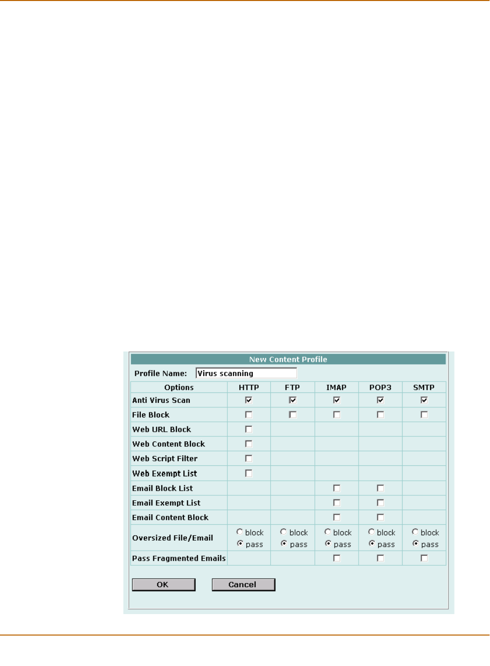
248 Fortinet Inc.
Antivirus scanning Antivirus protection
Antivirus scanning
Virus scanning intercepts most files (including files compressed with up to 12 layers of
compression using zip, rar, gzip, tar, upx, and OLE) in the content streams for which
you enable antivirus protection. Each file is tested to determine the file type and the
most effective method of scanning the file for viruses. For example, binary files are
scanned using binary virus scanning and Microsoft Office files containing macros are
scanned for macro viruses.
FortiWiFi virus scanning does not scan the following file types:
• cdimage
• floppy image
•.ace
•.bzip2
•.Tar+Gzip+Bzip2
If a file is found to contain a virus, the FortiWiFi unit removes the file from the content
stream and replaces it with a replacement message.
To scan FortiWiFi firewall traffic for viruses
1Select antivirus scanning in a content profile.
For information about content profiles, see “Adding content profiles” on page 190.
2Add this content profile to firewall policies to apply virus scanning to the traffic
controlled by the firewall policy.
See “Adding content profiles to policies” on page 192.
Figure 34: Example content profile for virus scanning

Antivirus protection File blocking
FortiWiFi-60 Installation and Configuration Guide 249
File blocking
Enable file blocking to remove all files that are a potential threat and to provide the
best protection from active computer virus attacks. Blocking files is the only protection
from a virus that is so new that antivirus scanning cannot detect it. You would not
normally operate the FortiWiFi unit with blocking enabled. However, it is available for
extremely high-risk situations in which there is no other way to prevent viruses from
entering your network.
File blocking deletes all files that match a list of enabled file patterns. The FortiWiFi
unit replaces the file with an alert message that is forwarded to the user. The FortiWiFi
unit also writes a message to the virus log and sends an alert email if it is configured
to do so.
By default, when blocking is enabled, the FortiWiFi unit blocks the following file
patterns:
• executable files (*.bat, *.com, and *.exe)
• compressed or archive files (*.gz, *.rar, *.tar, *.tgz, and *.zip)
• dynamic link libraries (*.dll)
• HTML application (*.hta)
• Microsoft Office files (*.doc, *.ppt, *.xl?)
• Microsoft Works files (*.wps)
• Visual Basic files (*.vb?)
• screen saver files (*.scr)
Blocking files in firewall traffic
Use content profiles to apply file blocking to HTTP, FTP, POP3, IMAP, and SMTP
traffic controlled by firewall policies.
To block files in firewall traffic
1Select file blocking in a content profile.
See “Adding content profiles” on page 190.
2Add this content profile to firewall policies to apply content blocking to the traffic
controlled by the firewall policy.
See “Adding content profiles to policies” on page 192.
Adding file patterns to block
To add file patterns to block
1Go to Anti-Virus > File Block.
2Select New.
Note: If both blocking and scanning are enabled, the FortiWiFi unit blocks files that match
enabled file patterns and does not scan these files for viruses.

250 Fortinet Inc.
Blocking oversized files and emails Antivirus protection
3Type the new pattern in the File Pattern field.
You can use an asterisk (*) to represent any characters and a question mark (?) to
represent any single character. For example, *.dot blocks Microsoft Word template
files and *.do? blocks both Microsoft Word template files and document files.
4Select the check box beside the traffic protocols for which you want to enable blocking
of this file pattern.
5Select OK.
Blocking oversized files and emails
You can configure the FortiWiFi unit to buffer 1 to 15 percent of available memory to
store oversized files and email. The FortiWiFi unit then blocks a file or email that
exceeds this limit instead of bypassing antivirus scanning and sending the file or email
directly to the server or receiver. The FortiWiFi unit sends a replacement message for
an oversized file or email attachment to the HTTP or email proxy client.
Configuring limits for oversized files and email
To configure limits for oversized files and email
1Go to Anti-Virus > Config > Config.
2Type the size limit, in MB.
3Select Apply.
Exempting fragmented email from blocking
A fragmented email is a large email message that has been split into smaller
messages that are sent individually and recombined when they are received. By
default, when antivirus protection is enabled, the FortiWiFi unit blocks fragmented
emails and replaces them with an email block message that is forwarded to the
receiver. It is recommended that you disable the fragmenting of email messages in the
client email software.
To exempt fragmented emails from automatic antivirus blocking
1Enable Pass Fragmented Emails for IMAP, POP3, and SMTP traffic in a content
profile.
2Select Anti-Virus & Web filter in a firewall policy. For example, to pass fragmented
emails that internal users send to the external network, select an internal to external
policy.
!Caution: The FortiWiFi unit cannot scan fragmented emails for viruses or use file pattern
blocking to remove files from these email messages.

Antivirus protection Viewing the virus list
FortiWiFi-60 Installation and Configuration Guide 251
3Select a content profile that has Pass Fragmented Emails enabled for the traffic that
you want the FortiWiFi unit to scan.
Viewing the virus list
You can view the names of the viruses and worms in the current virus definition list.
To view the virus list
1Go to Anti-Virus > Config > Virus List.
2Scroll through the virus and worm list to view the names of all viruses and worms in
the list.

252 Fortinet Inc.
Viewing the virus list Antivirus protection

FortiWiFi-60 Installation and Configuration Guide Version 2.50
FortiWiFi-60 Installation and Configuration Guide 253
Web filtering
When you enable Anti-Virus & Web filter in a firewall policy, you select a content
profile that controls how web filtering behaves for HTTP traffic. Content profiles control
the following types of content filtering:
• blocking unwanted URLs,
• blocking unwanted content,
• removing scripts from web pages,
• exempting URLs from blocking.
You can also use the Cerberian URL filtering to block unwanted URLs. For more
information, see “Configuring Cerberian URL filtering” on page 260.
This chapter describes:
•General configuration steps
•Content blocking
•URL blocking
•Configuring Cerberian URL filtering
•Script filtering
•Exempt URL list
General configuration steps
Configuring web filtering involves the following general steps:
1Select web filtering options in a new or existing content profile. See “Adding content
profiles” on page 190.
2Select the Anti-Virus & Web filter option in firewall policies that allow HTTP
connections through the FortiWiFi unit.
• Select a content profile that provides the web filtering options that you want to
apply to a policy. See “Adding content profiles to policies” on page 192.

254 Fortinet Inc.
Content blocking Web filtering
3Configure web filtering settings to control how the FortiWiFi unit applies web filtering to
the HTTP traffic allowed by policies. See:
•“URL blocking” on page 257,
•“Configuring Cerberian URL filtering” on page 260,
•“Content blocking” on page 254,
•“Script filtering” on page 262,
•“Exempt URL list” on page 263.
4Configure the messages that users receive when the FortiWiFi unit blocks unwanted
content or unwanted URLs. See “Replacement messages” on page 155.
5Configure the FortiWiFi unit to record log messages when it blocks unwanted content
or unwanted URLs. See “Recording logs” on page 273.
6Configure the FortiWiFi unit to send an alert email when it blocks unwanted content or
unwanted URLs. See “Configuring alert email” on page 281.
Content blocking
When the FortiWiFi unit blocks a web page, the user who requested the blocked page
receives a block message and the FortiWiFi unit writes a message to the web filtering
log.
You can add banned words to the list in many languages using Western, Simplified
Chinese, Traditional Chinese, Japanese, or Korean character sets.
•Adding words and phrases to the Banned Word list
•Clearing the Banned Word list
•Backing up the Banned Word list
•Restoring the Banned Word list
Adding words and phrases to the Banned Word list
1Go to Web Filter > Content Block.
2Select New to add a word or phrase to the Banned Word list.
3Choose a language or character set for the banned word or phrase.
You can choose Western, Chinese Simplified, Chinese Traditional, Japanese, or
Korean.
Your computer and web browser must be configured to enter characters in the
character set that you choose.
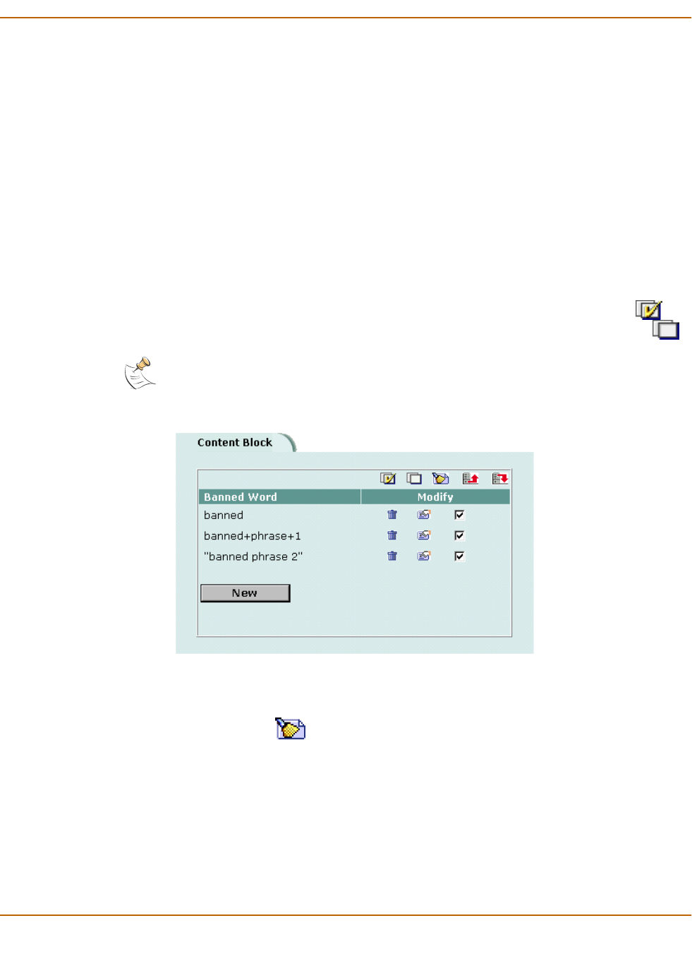
Web filtering Content blocking
FortiWiFi-60 Installation and Configuration Guide 255
4Type a banned word or phrase.
If you type a single word (for example, banned), the FortiWiFi unit blocks all web
pages that contain that word.
If you type a phrase (for example, banned phrase), the FortiWiFi unit blocks web
pages that contain both words. When this phrase appears on the banned word list, the
FortiWiFi unit inserts plus signs (+) in place of spaces (for example,
banned+phrase).
If you type a phrase in quotes (for example, “banned word”), the FortiWiFi unit
blocks all web pages in which the words are found together as a phrase.
Content filtering is not case-sensitive. You cannot include special characters in
banned words.
5To enable the banned word, ensure that the Enable checkbox is selected.
6Select OK.
The word or phrase is added to the Banned Word list.
You can enable all the words on the banned word list by selecting Check All .
You can disable all the words on the banned word list by selecting Uncheck All .
Figure 35: Example banned word list
Clearing the Banned Word list
1Go to Web Filter > Content Block.
2Select Clear List to remove all banned words and phrases from the banned word
list.
Backing up the Banned Word list
You can back up the banned word list by downloading it to a text file on the
management computer.
To back up the banned word list
1Go to Web Filter > Content Block.
Note: Banned Word must be selected in the content profile for web pages containing banned
words to be blocked.
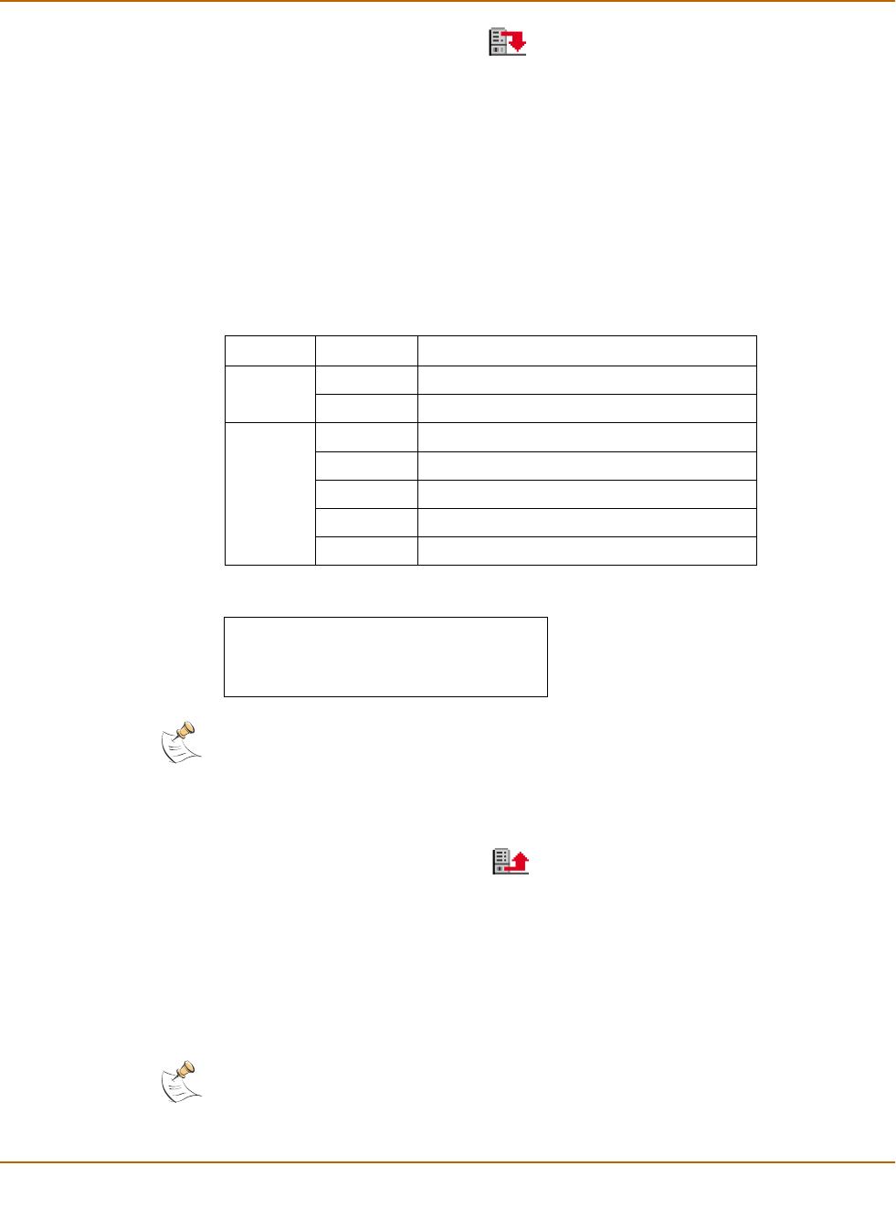
256 Fortinet Inc.
Content blocking Web filtering
2Select Backup Banned Word List .
The FortiWiFi unit downloads the list to a text file on the management computer. You
can specify a location to which to download the text file as well as a name for the text
file.
Restoring the Banned Word list
You can create a Banned Word list in a text editor and then upload the text file to the
FortiWiFi unit. Add one banned word or phrase to each line of the text file. The word or
phrase should be followed by two parameters separated by spaces. The first
parameter specifies the status of the entry. The second parameter specifies the
language of the entry.
Figure 36: Example Banned Word List text file
To restore the banned word list
1Go to Web Filter > Content Block.
2Select Restore Banned Word List .
3Type the path and filename of the banned word list text file, or select Browse and
locate the file.
4Select OK to upload the file to the FortiWiFi unit.
5Select Return to display the updated Banned Word List.
6You can continue to maintain the Banned Word List by making changes to the text file
and uploading it again as necessary.
.
Table 21: Banned Word list configuration parameters
Parameter Setting Description
Status 0 Disabled
1 Enabled
Language 0 ASCII
1 Simplified Chinese
2 Traditional Chinese
3 Japanese
4 Korean
banned 1 0
banned+phrase+1 1 3
"banned+phrase+2" 1 1
Note: All changes made to the banned word list using the web-based manager are lost when
you upload a new list. However, you can download your current banned word list, add more
items to it using a text editor, and then upload the edited list to the FortiWiFi unit.
Note: Banned Word must be selected in the content profile for web pages containing banned
words to be blocked.

Web filtering URL blocking
FortiWiFi-60 Installation and Configuration Guide 257
URL blocking
You can block the unwanted web URLs using FortiWiFi Web URL blocking, FortiWiFi
Web pattern blocking, and Cerberian web filtering.
•Configuring FortiWiFi Web URL blocking
•Configuring FortiWiFi Web pattern blocking
•Configuring Cerberian URL filtering
Configuring FortiWiFi Web URL blocking
You can configure FortiWiFi Web URL blocking to block all pages on a website by
adding the top-level URL or IP address. You can also block individual pages on a
website by including the full path and filename of the web page to block.
•Adding URLs to the Web URL block list
•Clearing the Web URL block list
•Downloading the Web URL block list
•Uploading a URL block list
Adding URLs to the Web URL block list
1Go to Web Filter > Web URL Block.
2Select New to add a URL to the Web URL block list.
3Type the URL the you want to block.
Type a top-level URL or IP address to block access to all pages on a website. For
example, www.badsite.com or 122.133.144.155 blocks access to all pages at
this website.
Type a top-level URL followed by the path and filename to block access to a single
page on a website. For example, www.badsite.com/news.html or
122.133.144.155/news.html blocks the news page on this website.
To block all pages with a URL that ends with badsite.com, add badsite.com to
the block list. For example, adding badsite.com blocks access to
www.badsite.com,mail.badsite.com,www.finance.badsite.com, and so
on.
4Ensure that the Enable checkbox has been selected and then select OK.
Note: Do not include http:// in the URL that you want to block.
Note: Do not use regular expressions in the Web URL block list. You can use regular
expressions in the Web Pattern Block list to create URL patterns to block. See “Configuring
FortiWiFi Web pattern blocking” on page 259.
Note: You can type a top-level domain suffix (for example, “com” without the leading period) to
block access to all URLs with this suffix.
Note: URL blocking does not block access to other services that users can access with a web
browser. For example, URL blocking does not block access to ftp://ftp.badsite.com.
Instead, you can use firewall policies to deny FTP connections.
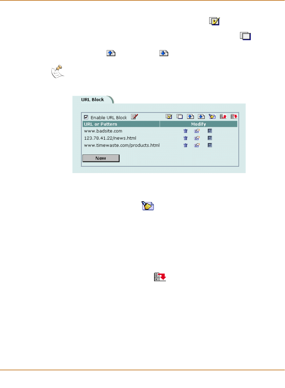
258 Fortinet Inc.
URL blocking Web filtering
5Select OK to add the URL to the Web URL block list.
You can enter multiple URLs and then select Check All to enable all items in the
Web URL block list.
You can disable all of the URLs on the list by selecting Uncheck All .
Each page of the Web URL block list displays 100 URLs.
6Use Page Up and Page Down to navigate through the Web URL block list.
Figure 37: Example URL block list
Clearing the Web URL block list
1Go to Web Filter > Web URL Block.
2Select Clear URL Block List to remove all URLs and patterns from the Web URL
block list.
Downloading the Web URL block list
You can back up the Web URL block list by downloading it to a text file on the
management computer.
To download a Web URL block list
1Go to Web Filter > Web URL Block.
2Select Download URL Block List .
The FortiWiFi unit downloads the list to a text file on the management computer. You
can specify a location to which to download the text file as well as a name for the text
file.
Uploading a URL block list
You can create a URL block list in a text editor and then upload the text file to the
FortiWiFi unit. Add one URL or pattern to each line of the text file. You can follow the
item with a space and then a 1 to enable or a zero (0) to disable the URL. If you do not
add this information to the text file, the FortiWiFi unit automatically enables all URLs
and patterns that are followed by a 1 or no number when you upload the text file.
Note: You must select the Web URL Block option in the content profile to enable the URL
blocking.

Web filtering URL blocking
FortiWiFi-60 Installation and Configuration Guide 259
Figure 38: Example URL block list text file
You can either create the URL block list or add a URL list created by a third-party URL
block or blacklist service. For example, you can download the squidGuard blacklists
available at http://www.squidguard.org/blacklist/ as a starting point for creating a URL
block list. Three times per week, the squidGuard robot searches the web for new
URLs to add to the blacklists. You can upload the squidGuard blacklists to the
FortiWiFi unit as a text file, with only minimal editing to remove comments at the top of
each list and to combine the lists that you want into a single file.
To upload a URL block list
1In a text editor, create the list of URLs and patterns that you want to block.
2Using the web-based manager, go to Web Filter > Web URL Block.
3Select Upload URL Block List .
4Type the path and filename of the URL block list text file, or select Browse and locate
the file.
5Select OK to upload the file to the FortiWiFi unit.
6Select Return to display the updated Web URL block list.
Each page of the Web URL block list displays 100 URLs.
7Use Page Down and Page Up to navigate through the Web URL block list.
8You can continue to maintain the Web URL block list by making changes to the text
file and uploading it again.
Configuring FortiWiFi Web pattern blocking
You can configure FortiWiFi web pattern blocking to block web pages that match a
URL pattern. Create URL patterns using regular expressions (for example,
badsite.* matches badsite.com,badsite.org,badsite.net and so on).
FortiWiFi web pattern blocking supports standard regular expressions. You can add
up to 20 patterns to the web pattern block list.
To add patterns to the Web pattern block list
1Go to Web Filter > URL Block > Web Pattern Block.
2Select New to add an item to the Web pattern block list.
3Type the web pattern that you want to block.
You can use standard regular expressions for web patterns.
www.badsite.com/index 1
www.badsite.com/products 1
182.63.44.67/index 1
Note: All changes made to the URL block list using the web-based manager are lost when you
upload a new list. However, you can download your current URL block list, add more items to it
using a text editor, and then upload the edited list to the FortiWiFi unit.

260 Fortinet Inc.
Configuring Cerberian URL filtering Web filtering
4Select Enable to block the pattern.
5Select OK to add the pattern to the Web pattern block list.
Configuring Cerberian URL filtering
The FortiWiFi unit supports Cerberian URL filtering. For information about Cerberian
URL filtering, see www.cerberian.com.
If you have purchased the Cerberian web filtering functionality with your FortiWiFi unit,
use the following configuration procedures to configure FortiWiFi support for
Cerberian web filtering.
•Installing a Cerberian license key
•Adding a Cerberian user
•Configuring Cerberian web filter
•Enabling Cerberian URL filtering
Installing a Cerberian license key
Before you can use the Cerberian web filter, you must install a license key. The
license key determines the number of end users allowed to use Cerberian web
filtering through the FortiWiFi unit.
To install a Cerberian licence key
1Go to Web Filter > URL Block.
2Select Cerberian URL Filtering.
3Enter the license number.
4Select Apply.
Adding a Cerberian user
The Cerberian web policies can be applied only to user groups. You can add users on
the FortiWiFi unit and then add the users to user groups on the Cerberian
administration web site.
When the end user tries to access a URL, the FortiWiFi unit checks whether the user’s
IP address is in the IP address list on the FortiWiFi unit. If the user’s IP address is in
the list, the request is sent to the Cerberian server. Otherwise, an error message is
sent to the user saying that the user does not have authorized access to the
Cerberian web filter.
Note: URL blocking does not block access to other services that users can access with a web
browser. For example, URL blocking does not block access to ftp://ftp.badsite.com.
Instead, you can use firewall policies to deny FTP connections.
Note: You must select the Web URL Block option in the content profile to enable the URL
blocking.

Web filtering Configuring Cerberian URL filtering
FortiWiFi-60 Installation and Configuration Guide 261
To add a Cerberian user
1Go to Web Filter > URL Block.
2Select Cerberian URL Filtering.
3Select New.
4Enter the IP address and netmask of the user computers.
You can enter the IP address of a single user. For example, 192.168.100.19
255.255.255.255. You can also enter a subnet of a group of users. For example,
192.168.100.0 255.255.255.0.
5Enter an alias for the user.
The alias is used as the user name when you add the user to a user group on the
Cerberian server. If you do not enter an alias, the user’s IP is used and added to the
default group on the Cerberian server.
6Select OK.
Configuring Cerberian web filter
After you add the Cerberian web filter users on the FortiWiFi unit, you can add these
users to the user groups on the Cerberian web filter server. Then you can create
policies and apply these policies to the user groups.
About the default group and policy
There is a default user group, which is associated with a default policy, that exists on
the Cerberian web filter server.
You can add users to the default group and apply any policies to the group.
Use the default group to add:
• All the users who are not assigned alias names on the FortiWiFi unit.
• All the users who are not assigned to other user groups.
The Cerberian web filter groups URLs into 53 categories. The default policy blocks the
URLs of 12 categories. You can modify the default policy and apply it to any user
groups.
To configure Cerberian web filtering
1Add the user name, which is the alias you added on the FortiWiFi unit, to a user group
on the Cerberian server.
Web policies can be applied only to user groups. If you did not enter an alias for a
user’s IP address on the FortiWiFi unit, the user’s IP address is automatically added
to the default Cerberian group.
2Create policies by selecting the web categories that you want to block.
3Apply the policy to a user group that contains the user.
For detailed procedures, see the online help on the Cerberian Web Filter web page.

262 Fortinet Inc.
Script filtering Web filtering
Enabling Cerberian URL filtering
After you add the Cerberian users and groups and configure the Cerberian web filter,
you can enable Cerberian URL filtering.
To enable cerberian URL filtering
1Go to Web Filter > URL Block > Cerberian URL Filtering.
2Select the Cerberian URL Filtering option.
3Go to Firewall > Content Profile.
4Create a new or select an existing content profile and enable Web URL Block.
5Go to Firewall > Policy.
6Create a new or select an existing policy.
7Select Anti-Virus & Web filter.
8Select the content profile from the Content Profile list.
9Select OK.
Script filtering
You can configure the FortiWiFi unit to remove Java applets, cookies, and ActiveX
scripts from the HTML web pages.
•Enabling script filtering
•Selecting script filter options
Enabling script filtering
1Go to Firewall > Content Profile.
2Select the content profile for which you want to enable script filtering.
3Select Script Filter.
4Select OK.
Selecting script filter options
1Go to Web Filter > Script Filter.
2Select the script filter options that you want to enable.
You can block Java applets, cookies, and ActiveX.
3Select Apply.
Note: Blocking any of these items might prevent some web pages from working properly.
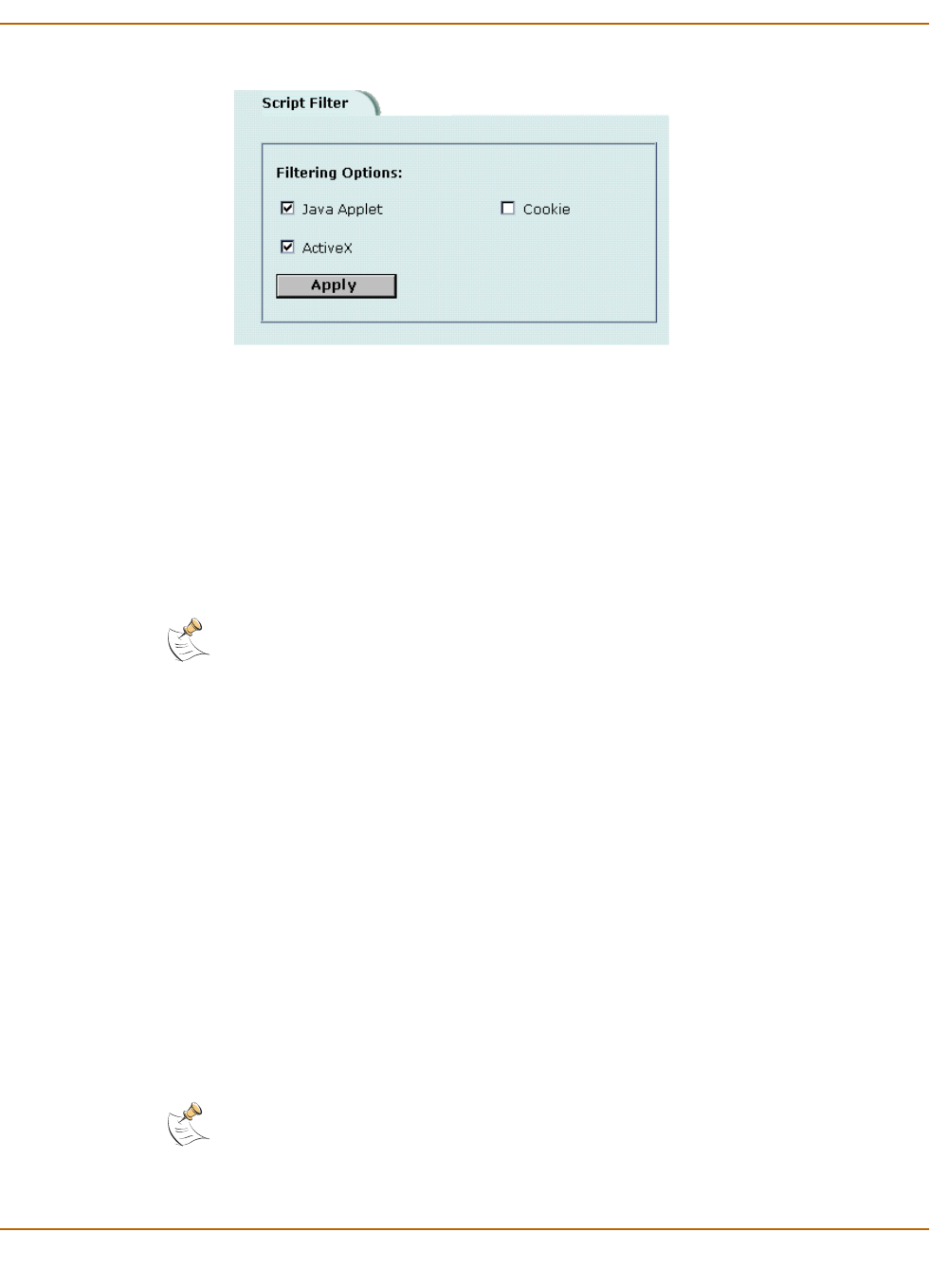
Web filtering Exempt URL list
FortiWiFi-60 Installation and Configuration Guide 263
Figure 39: Example script filter settings to block Java applets and ActiveX
Exempt URL list
Add URLs to the exempt URL list to allow legitimate traffic that might otherwise be
blocked by content or URL blocking. For example, if content blocking is set to block
pornography-related words and a reputable website runs a story on pornography, web
pages from the reputable website are blocked. Adding the address of the reputable
website to the exempt URL list allows the content of the website to bypass content
blocking.
•Adding URLs to the URL Exempt list
•Downloading the URL Exempt List
•Uploading a URL Exempt List
Adding URLs to the URL Exempt list
1Go to Web Filter > URL Exempt.
2Select New to add an item to the URL Exempt list.
3Type the URL to exempt.
Type a complete URL, including path and filename, to exempt access to a page on a
website. For example, www.goodsite.com/index.html exempts access to the
main page of this example website. You can also add IP addresses; for example,
122.63.44.67/index.html exempts access to the main web page at this
address. Do not include http:// in the URL to exempt.
Exempting a top-level URL, such as www.goodsite.com, exempts all requested
subpages (for example, www.goodsite.com/badpage) from all content and URL
filtering rules.
Note: Content downloaded from exempt web pages is not blocked or scanned by antivirus
protection.
Note: Exempting a top-level URL does not exempt pages such as mail.goodsite.com from
all content and URL filtering rules unless goodsite.com (without the www) is added to the
exempt URL list.
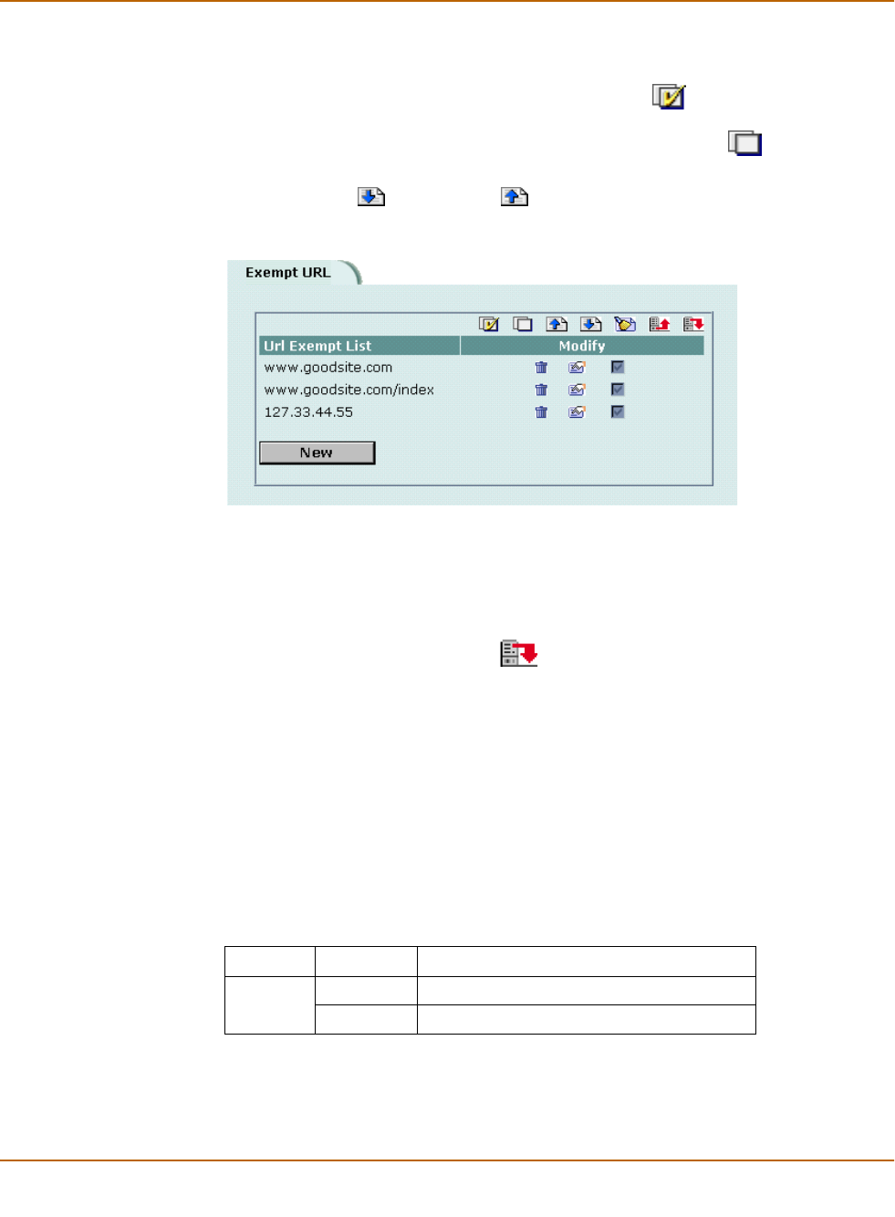
264 Fortinet Inc.
Exempt URL list Web filtering
4Ensure that the Enable checkbox has been selected.
5Select OK to add the URL to the exempt URL list.
You can enter multiple URLs and then select Check All to activate all items in the
exempt URL list.
You can disable all the URLs in the list by selecting Uncheck All .
Each page of the exempt URL list displays 100 URLs.
6Use Page Down and Page Up to navigate the exempt URL list.
Figure 40: Example URL Exempt list
Downloading the URL Exempt List
You can back up the URL Exempt List by downloading it to a text file on the
management computer.
1Go to Web Filter > URL Exempt.
2Select Download URL Exempt List .
The FortiWiFi unit downloads the list to a text file on the management computer. You
can specify a location to which to download the text file as well as a name for the text
file.
Uploading a URL Exempt List
You can create a URL Exempt list in a text editor and then upload the text file to the
FortiWiFi unit. Add one URL or pattern to each line of the text file. The word or phrase
should be followed by a parameter specifying the status of the entry. If you do not add
this information to the text file, the FortiWiFi unit automatically enables all URLs and
patterns that are followed with a 1 or no number when you upload the text file.
Table 22: URL Exempt list configuration parameters
Parameter Setting Description
Status 0 Disabled
1 Enabled
Web filtering Exempt URL list
FortiWiFi-60 Installation and Configuration Guide 265
Figure 41: Example URL Exempt list text file
.
1In a text editor, create the list of URLs to exempt.
2Using the web-based manager, go to Web Filter > URL Exempt.
3Select Upload URL Exempt List .
4Type the path and filename of your URL Exempt List text file, or select Browse and
locate the file.
5Select OK to upload the file to the FortiWiFi unit.
6Select Return to display the updated URL Exempt List.
7You can continue to maintain the URL Exempt List by making changes to the text file
and uploading it again as necessary.
www.goodsite.com 1
www.goodsite.com/index 1
127.33.44.55 1
Note: All changes made to the URL block list using the web-based manager are lost when you
upload a new list. However, you can download your current URL block list, add more items to it
using a text editor, and then upload the edited list to the FortiWiFi unit.

266 Fortinet Inc.
Exempt URL list Web filtering

FortiWiFi-60 Installation and Configuration Guide Version 2.50
FortiWiFi-60 Installation and Configuration Guide 267
Email filter
Email filtering is enabled in firewall policies. When you enable Anti-Virus & Web filter
in a firewall policy, you select a content profile that controls how email filtering
behaves for email (IMAP and POP3) traffic. Content profiles control the following
types of protection to identify unwanted email:
• filtering unwanted sender address patterns,
• filtering unwanted content,
• exempting sender address patterns from blocking.
This chapter describes:
•General configuration steps
•Email banned word list
•Email block list
•Email exempt list
•Adding a subject tag
General configuration steps
Configuring email filtering involves the following general steps:
1Select email filter options in a new or existing content profile. See “Adding content
profiles” on page 190.
2Select the Anti-Virus & Web filter option in firewall policies that allow IMAP and POP3
connections through the FortiWiFi unit. Select a content profile that provides the email
filtering options that you want to apply to a policy. See “Adding content profiles to
policies” on page 192.
3Add a subject tag to the unwanted email so that receivers can use their mail client
software to filter messages based on the tag. See “Adding a subject tag” on page 272.
Note: For information about receiving email filter log messages, see “Configuring logging” in the
FortiGate Logging Configuration and Reference Guide. For information about email filter log
message categories and formats, see “Log messages” in the FortiGate Logging Configuration
and Reference Guide.

268 Fortinet Inc.
Email banned word list Email filter
Email banned word list
When the FortiWiFi unit detects an email that contains a word or phrase in the banned
word list, the FortiWiFi unit adds a tag to the subject line of the email and writes a
message to the event log. Receivers can then use their mail client software to filter
messages based on the subject tag.
You can add banned words to the list in many languages using Western, Simplified
Chinese, Traditional Chinese, Japanese, or Korean character sets.
•Adding words and phrases to the email banned word list
•Downloading the email banned word list
•Uploading the email banned word list
Adding words and phrases to the email banned word list
To add a word or phrase to the banned word list
1Go to Email Filter > Content Block.
2Select New.
3Type a banned word or phrase.
• If you type a single word (for example, banned), the FortiWiFi unit tags all IMAP
and POP3 email that contains that word.
• If you type a phrase (for example, banned phrase), the FortiWiFi unit tags email
that contains both words. When this phrase appears on the banned word list, the
FortiWiFi unit inserts plus signs (+) in place of spaces (for example,
banned+phrase).
• If you type a phrase in quotes (for example, “banned word”), the FortiWiFi unit
tags all email in which the words are found together as a phrase.
Content filtering is not case-sensitive. You cannot include special characters in
banned words.
1Select the Language for the banned word or phrase.
You can choose Western, Chinese Simplified, Chinese Traditional, Japanese, or
Korean.
Your computer and web browser must be configured to enter characters in the
language that you select.
2Select OK.
The word or phrase is added to the banned word list.
Note: Email Content Block must be selected in the content profile for IMAP or POP3 email
containing banned words to be tagged.
Email filter Email banned word list
FortiWiFi-60 Installation and Configuration Guide 269
Downloading the email banned word list
You can back up the banned word list by downloading it to a text file on the
management computer:
To download the banned word list
1Go to Email Filter > Content Block.
2Select Download.
The FortiWiFi unit downloads the banned word list to a text file on the management
computer. You can specify a location to which to download the text file as well as a
name for the text file.
Uploading the email banned word list
You can create or edit a banned word list in a text file and upload it from your
management computer to the FortiWiFi unit.
Each banned word or phrase must appear on a separate line in the text file. Use
ASCII, Western, Chinese Simplified, Chinese Traditional, Japanese, or Korean
characters. Your computer and web browser must be configured to enter characters in
the character set that you use.
All words are enabled by default. Optionally, you can enter a space and a 1 after the
word to enable it, and another space and a number to indicate the language.
If you do not add this information to all items in the text file, the FortiWiFi unit
automatically enables all banned words and phrases that are followed with a 1 or no
number in the Western language when you upload the text file.
Figure 42: Example Western email banned word list text file
To upload the banned word list
1Go to Email Filter > Content Block.
2Select Upload.
3Type the path and filename of the banned word list text file or select Browse and
locate the file.
4Select OK to upload the banned word list text file.
Select Return to display the banned word list.
0Western
1 Chinese Simplified
2 Chinese Traditional
3 Japanese
4Korean
banned 1 0
banned+phrase+1 1 0
“banned phrase 2” 1 0

270 Fortinet Inc.
Email block list Email filter
Email block list
You can configure the FortiWiFi unit to tag all IMAP and POP3 protocol traffic sent
from unwanted email addresses. When the FortiWiFi unit detects an email sent from
an unwanted address pattern, the FortiWiFi unit adds a tag to the subject line of the
email and writes a message to the email filter log. Receivers can then use their mail
client software to filter messages based on the subject tag.
You can tag email from a specific sender address or from all address subdomains by
adding the top-level domain name. Alternatively, you can tag email sent from
individual subdomains by including the subdomain to block.
•Adding address patterns to the email block list
•Downloading the email block list
•Uploading an email block list
Adding address patterns to the email block list
To add an address pattern to the email block list
1Go to Email Filter > Block List.
2Select New.
3Type a Block Pattern.
• To tag email from a specific email address, type the email address. For example,
sender@abccompany.com.
• To tag email from a specific domain, type the domain name. For example,
abccompany.com.
• To tag email from a specific subdomain, type the subdomain name. For example,
mail.abccompany.com.
• To tag email from an entire organization category, type the top-level domain name.
For example, type com to tag email sent from all organizations that use .com as the
top-level domain.
The pattern can contain numbers (0-9), uppercase and lowercase letters (A-Z, a-z),
and the special characters - (hyphen),_ (underscore), and @. Spaces and other
special characters are not allowed.
4Select OK to add the address pattern to the Email Block list.
Downloading the email block list
You can back up the email block list by downloading it to a text file on the
management computer.
To download the email block list
1Go to Email Filter > Block List.
2Select Download.
The FortiWiFi unit downloads the list to a text file on the management computer. You
can specify a location to which to download the text file as well as a name for the text
file.
Email filter Email exempt list
FortiWiFi-60 Installation and Configuration Guide 271
Uploading an email block list
You can create a email block list in a text editor and then upload the text file to the
FortiWiFi unit. Add one pattern to each line of the text file. You can follow the pattern
with a space and then a 1 to enable or a zero (0) to disable the pattern. If you do not
add this information to the text file, the FortiWiFi unit automatically enables all patterns
that are followed with a 1 or no number when you upload the text file.
Figure 43: Example email block list text file
You can either create the email block list yourself, or add a block list created by a
third-party email blacklist service. For example, you can subscribe to the Realtime
Blackhole List service available at http://mail-abuse.org/rbl/ as a starting point for
creating your own email block list. You can upload blacklists to the FortiWiFi unit as
text files, with only minimal editing to remove comments at the top of each list and to
combine the lists that you want into a single file.
To upload the email block list
1In a text editor, create the list of patterns to block.
2Using the web-based manager, go to Email Filter > Block List.
3Select Upload.
4Type the path and filename of your email block list text file, or select Browse and
locate the file.
5Select OK to upload the file to the FortiWiFi unit.
6Select Return to display the updated email block list.
7You can continue to maintain the email block list by making changes to the text file
and uploading it again.
Email exempt list
Add address patterns to the exempt list to allow legitimate IMAP and POP3 traffic that
might otherwise be tagged by email or content blocking. For example, if the email
banned word list is set to block email that contains pornography-related words and a
reputable company sends email that contains these words, the FortiWiFi unit would
normally add a subject tag to the email. Adding the domain name of the reputable
company to the exempt list allows IMAP and POP3 traffic from the company to bypass
email and content blocking.
mail.badsite.com 1
suredeal.org 1
user1@badsite.com 1
Note: All changes made to the email block list using the web-based manager are lost when you
upload a new list. However, you can download your current email block list, add more patterns
to it using a text editor, and then upload the edited list to the FortiWiFi unit.

272 Fortinet Inc.
Adding a subject tag Email filter
Adding address patterns to the email exempt list
To add an address pattern to the email exempt list
1Go to Email Filter > Exempt List.
2Select New.
3Type the address pattern that you want to exempt.
• To exempt email sent from a specific email address, type the email address. For
example, sender@abccompany.com.
• To exempt email sent from a specific domain, type the domain name. For example,
abccompany.com.
• To exempt email sent from a specific subdomain, type the subdomain name. For
example, mail.abccompany.com.
• To exempt email sent from an entire organization category, type the top-level
domain name. For example, type net to exempt email sent from all organizations
that use .net as the top-level domain.
The pattern can contain numbers (0-9), uppercase and lowercase letters (A-Z, a-z),
and the special characters - (hyphen),_ (underscore), and @. Spaces and other
special characters are not allowed.
4Select OK to add the address pattern to the email exempt list.
Adding a subject tag
When the FortiWiFi unit receives email from an unwanted address or email that
contains an item in the email banned word list, the FortiWiFi unit adds a tag to the
subject line and sends the message to the destination email address. Email users can
use their mail client software to filter the messages based on the subject tag.
To add a subject tag
1Go to Email Filter > Config.
2Type the Subject Tag that you want to display in the subject line of email received from
unwanted addresses or that contains banned words. For example, type Unwanted
Mail.
3Select Apply.
The FortiWiFi unit adds the tag to the subject line of all unwanted email.
Note: Do not use quotation marks in the subject tags.

FortiWiFi-60 Installation and Configuration Guide Version 2.50
FortiWiFi-60 Installation and Configuration Guide 273
Logging and reporting
You can configure the FortiWiFi unit to log network activity from routine configuration
changes and traffic sessions to emergency events. You can also configure the
FortiWiFi unit to send alert email messages to inform system administrators about
events such as network attacks, virus incidents, and firewall and VPN events.
This chapter describes:
•Recording logs
•Filtering log messages
•Configuring traffic logging
•Viewing logs saved to memory
•Configuring alert email
Recording logs
You can configure logging to record logs to one or more of:
• a computer running a syslog server,
• a computer running a WebTrends firewall reporting server,
• the console.
You can also configure logging to record event, attack, antivirus, web filter, and email
filter logs to the FortiWiFi system memory, if your FortiWiFi unit does not contain a
hard disk. Logging to memory allows quick access to only the most recent log entries.
If the FortiWiFi unit restarts, the log entries are lost.
You can select the same or different severity levels for each log location. For example,
you might want to record only emergency and alert level messages to the FortiWiFi
memory and record all levels of messages on a remote computer.
For information about filtering the log types and activities that the FortiWiFi unit
records, see “Filtering log messages” on page 276. For information about traffic logs,
see “Configuring traffic logging” on page 277.
This section describes:
•Recording logs on a remote computer
•Recording logs on a NetIQ WebTrends server
•Recording logs in system memory
•Log message levels

274 Fortinet Inc.
Recording logs Logging and reporting
Recording logs on a remote computer
You can configure the FortiWiFi unit to record log messages on a remote computer.
The remote computer must be configured with a syslog server.
To record logs on a remote computer
1Go to Log&Report > Log Setting.
2Select the Log to Remote Host check box to send the logs to a syslog server.
3Type the IP address of the remote computer running syslog server software.
4Type the port number of the syslog server.
5Select the severity level for which you want to record log messages.
The FortiWiFi unit logs all levels of severity down to, but not lower than, the level you
choose. For example, if you want to record emergency, alert, critical, and error
messages, select Error.
See “Log message levels” on page 275.
6Select Config Policy.
• Select the Log type for which you want the FortiWiFi unit to record logs.
• For each Log type, select the activities for which you want the FortiWiFi unit to
record log messages.
For information about log types and activities, see “Filtering log messages” on
page 276 and “Configuring traffic logging” on page 277.
7Select OK.
8Select Apply.
Recording logs on a NetIQ WebTrends server
Use the following procedure to configure the FortiWiFi unit to record logs on a remote
NetIQ WebTrends firewall reporting server for storage and analysis. FortiWiFi log
formats comply with WebTrends Enhanced Log Format (WELF) and are compatible
with WebTrends NetIQ Security Reporting Center 2.0 and Firewall Suite 4.1. For more
information, see the Security Reporting Center and Firewall Suite documentation.
To record logs on a NetIQ WebTrends server
1Go to Log&Report > Log Setting.
2Select the Log in WebTrends Enhanced Log Format check box.
3Type the IP address of the NetIQ WebTrends firewall reporting server.
4Select the severity level for which you want to record log messages.
The FortiWiFi logs all levels of severity down to, but not lower than, the level you
choose. For example, if you want to record emergency, alert, critical, and error
messages, select Error.
See “Log message levels” on page 275.
Note: FortiWiFi traffic log messages include sent and received fields, which are optional but
required for drawing a WebTrends graph.

Logging and reporting Recording logs
FortiWiFi-60 Installation and Configuration Guide 275
5Select Config Policy.
To configure the FortiWiFi unit to filter the types of logs and events to record, use the
procedures in “Filtering log messages” on page 276 and “Configuring traffic logging”
on page 277.
6Select OK.
7Select Apply.
Recording logs in system memory
If your FortiWiFi unit does not contain a hard disk, you can configure the FortiWiFi unit
to reserve some system memory for storing current event, attack, antivirus, web filter,
and email filter log messages. Logging to memory allows quick access to only the
most recent log entries. The FortiWiFi unit can store a limited number of messages in
system memory. After all available memory is used, the FortiWiFi unit deletes the
oldest messages. If the FortiWiFi unit restarts, the log entries are lost.
To record logs in system memory
1Go to Log&Report > Log Setting.
2Select the Log to memory check box.
3Select the severity level for which you want to record log messages.
The FortiWiFi logs all levels of severity down to, but not lower than, the level you
choose. For example, if you want to record emergency, alert, critical, and error
messages, select Error.
See “Log message levels” on page 275.
4Select Config Policy.
To configure the FortiWiFi to filter the types of logs and events to record, use the
procedures in “Filtering log messages” on page 276.
5Select Apply.
Log message levels
Tab le 2 3 lists and describes FortiWiFi log message levels.
Note: The FortiWiFi unit can record only the event and attack log messages in system memory.
Table 23: FortiWiFi log message levels
Levels Description Generated by
0 - Emergency The system has become unstable. Emergency messages not
available.
1 - Alert Immediate action is required. NIDS attack log messages.
2 - Critical Functionality is affected. DHCP
3 - Error An error condition exists and
functionality could be affected.
Error messages not available.

276 Fortinet Inc.
Filtering log messages Logging and reporting
Filtering log messages
You can configure the logs that you want to record and the message categories that
you want to record in each log.
To filter log entries
1Go to Log&Report > Log Setting.
2Select Config Policy for the log location that you selected in “Recording logs” on
page 273.
3Select the log types that you want the FortiWiFi unit to record.
4Select the message categories that you want the FortiWiFi unit to record if you
selected Event Log, Virus Log, Web Filtering Log, Attack Log, Email Filter Log, or
Update in step 3.
5Select OK.
4 - Warning Functionality could be affected. Antivirus, Web filter, email filter, and
system event log messages.
5 - Notice Information about normal events. Antivirus, Web filter, and email filter
log messages.
6 - Information General information about system
operations.
Antivirus, Web filter, email filter log
messages, and other event log
messages.
Table 23: FortiWiFi log message levels
Levels Description Generated by
Traffic Log Record all connections to and through the interface.
To configure traffic filtering, see “Adding traffic filter entries” on page 279.
Event Log Record management and activity events in the event log.
Management events include changes to the system configuration as well
as administrator and user logins and logouts. Activity events include
system activities, such as VPN tunnel establishment and HA failover
events.
Virus Log Record virus intrusion events, such as when the FortiWiFi unit detects a
virus, blocks a file type, or blocks an oversized file or email.
Web Filtering Log Record activity events, such as URL and content blocking, and exemption
of URLs from blocking.
Attack Log Record attacks detected by the NIDS and prevented by the NIDS
Prevention module.
Email Filter Log Record activity events, such as detection of email that contains unwanted
content and email from unwanted senders.
Update Record log messages when the FortiWiFi connects to the FDN to
download antivirus and attack updates.
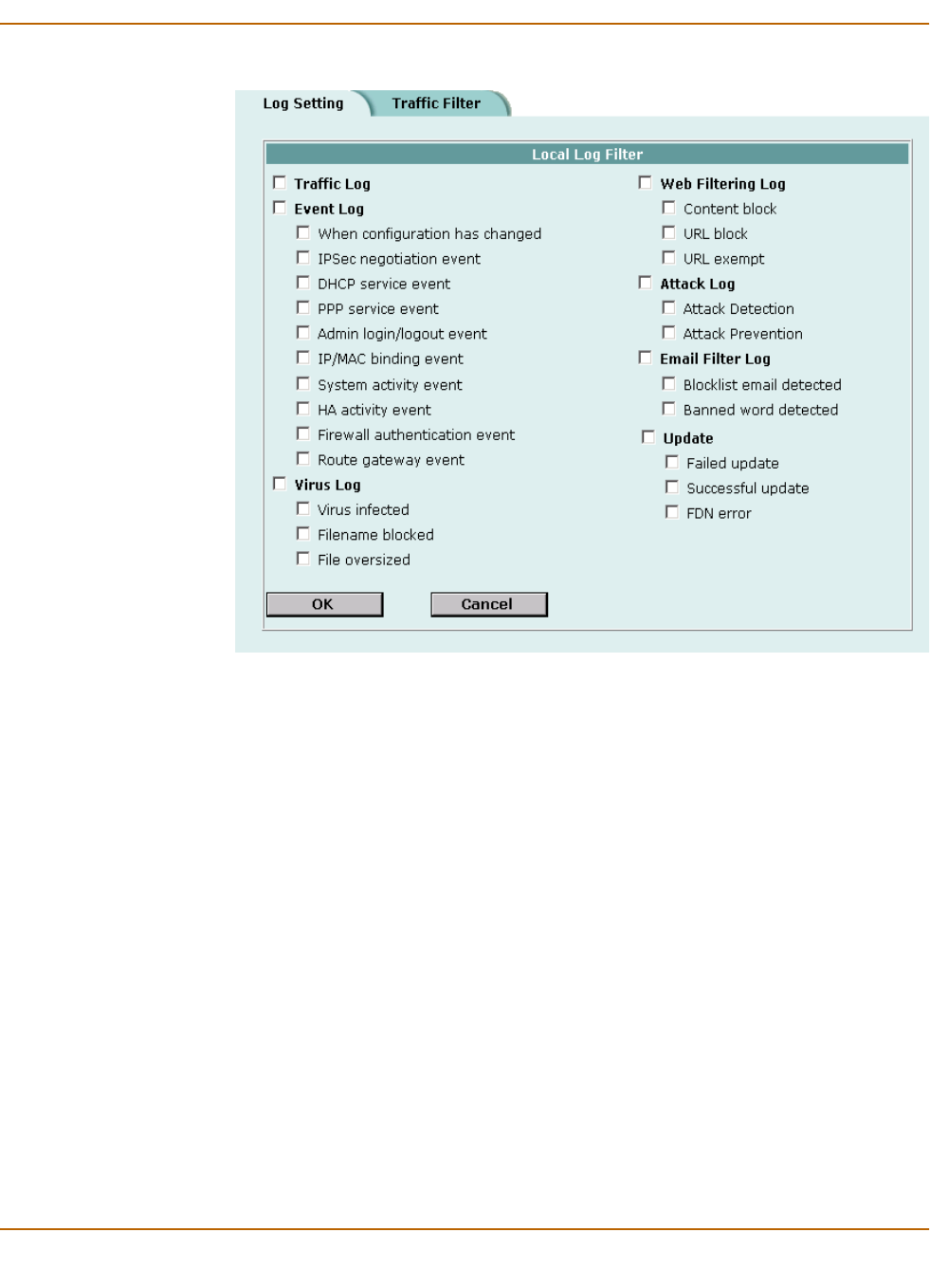
Logging and reporting Configuring traffic logging
FortiWiFi-60 Installation and Configuration Guide 277
Figure 44: Example log filter configuration
Configuring traffic logging
You can configure the FortiWiFi unit to record traffic log messages for connections to:
• An interface
• A firewall policy
The FortiWiFi unit can filter traffic logs for a source and destination address and
service. You can also enable the following global settings:
• resolve IP addresses to host names,
• display the port number or service.
The traffic filter list displays the name, source address and destination address, and
the protocol type of the traffic to be filtered.
This section describes:
•Enabling traffic logging
•Configuring traffic filter settings
•Adding traffic filter entries

278 Fortinet Inc.
Configuring traffic logging Logging and reporting
Enabling traffic logging
You can enable logging on any interface and firewall policy.
Enabling traffic logging for an interface
If you enable traffic logging for an interface, all connections to and through the
interface are recorded in the traffic log.
To enable traffic logging for an interface
1Go to System > Network > Interface.
2Select Edit in the Modify column beside the interface for which you want to
enable logging.
3For Log, select Enable.
4Select OK.
5Repeat this procedure for each interface for which you want to enable logging.
Enabling traffic logging for a firewall policy
If you enable traffic logging for a firewall policy, all connections accepted by the
firewall policy are recorded in the traffic log.
To enable traffic logging for a firewall policy
1Go to Firewall > Policy.
2Select a policy tab.
3Select Log Traffic.
4Select OK.
Configuring traffic filter settings
You can configure the information recorded in all traffic log messages.
To configure traffic filter settings
1Go to Log&Report > Log Setting > Traffic Filter.
2Select the settings that you want to apply to all traffic log messages.
3Select Apply.
Resolve IP Select Resolve IP if you want traffic log messages to list the IP address
and domain name stored on the DNS server. If the primary and secondary
DNS server addresses provided to you by your ISP have not already been
added, go to System > Network > DNS and add the addresses.
Display Select Port Number if you want traffic log messages to list the port
number, for example, 80/tcp. Select Service Name if you want traffic log
messages to list the name of the service, for example, TCP.
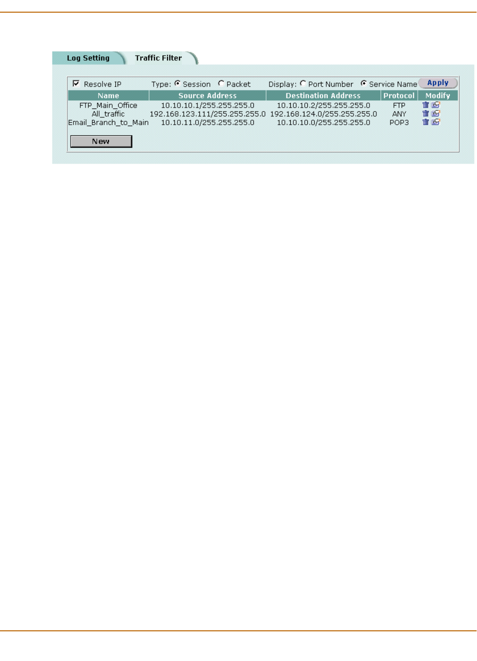
Logging and reporting Configuring traffic logging
FortiWiFi-60 Installation and Configuration Guide 279
Figure 45: Example traffic filter list
Adding traffic filter entries
Add entries to the traffic filter list to filter the messages that are recorded in the traffic
log. If you do not add any entries to the traffic filter list, the FortiWiFi unit records all
traffic log messages. You can add entries to the traffic filter list to limit the traffic logs
that are recorded. You can log traffic with a specified source IP address and netmask,
to a destination IP address and netmask, and for a specified service. A traffic filter
entry can include any combination of source and destination addresses and services.
To add an entry to the traffic filter list
1Go to Log&Report > Log Setting > Traffic Filter.
2Select New.
3Configure the traffic filter for the type of traffic that you want to record on the traffic log.
4Select OK.
The traffic filter list displays the new traffic address entry with the settings that you
selected in “Enabling traffic logging” on page 278.
Name Type a name to identify the traffic filter entry.
The name can contain numbers (0-9), uppercase and lowercase
letters (A-Z, a-z), and the special characters - and _. Spaces and
other special characters are not allowed.
Source IP Address
Source Netmask
Type the source IP address and netmask for which you want the
FortiWiFi unit to log traffic messages. The address can be an
individual computer, subnetwork, or network.
Destination IP Address
Destination Netmask
Type the destination IP address and netmask for which you want the
FortiWiFi unit to log traffic messages. The address can be an
individual computer, subnetwork, or network.
Service Select the service group or individual service for which you want the
FortiWiFi unit to log traffic messages.
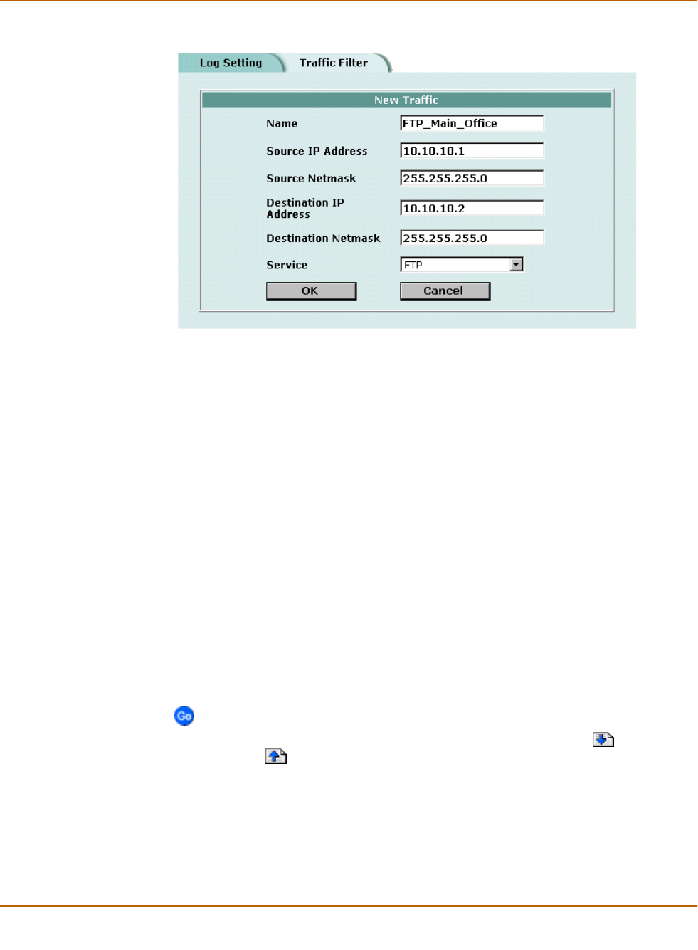
280 Fortinet Inc.
Viewing logs saved to memory Logging and reporting
Figure 46: Example new traffic address entry
Viewing logs saved to memory
If the FortiWiFi unit is configured to save log messages in system memory, you can
use the web-based manager to view, search, and clear the log messages. This
section describes:
•Viewing logs
•Searching logs
Viewing logs
Log messages are listed with the most recent message at the top.
To view log messages saved in system memory
1Go to Log&Report > Logging.
2Select Event Log, Attack Log, Antivirus Log, Web Filter Log, or Email Filter Log.
The web-based manager lists the log messages saved in system memory.
3Scroll through the log messages to view them.
4To view a specific line in the log, type a line number in the Go to line field and select
.
5To navigate through the log message pages, select Go to next page or Go to
previous page .
Searching logs
To search log messages saved in system memory
1Go to Log&Report > Logging.
Logging and reporting Configuring alert email
FortiWiFi-60 Installation and Configuration Guide 281
2Select Event Log, Attack Log, Antivirus Log, Web Filter Log, or Email Filter Log.
3Select to search the messages in the selected log.
4Select AND to search for messages that match all the specified search criteria.
5Select OR to search for messages that match one or more of the specified search
criteria.
6Select either of the following search criteria:
7Select OK to run the search.
The web-based manager displays the messages that match the search criteria. You
can scroll through the messages or run another search.
Configuring alert email
You can configure the FortiWiFi unit to send alert email to up to three email addresses
when there are virus incidents, block incidents, network intrusions, and other firewall
or VPN events or violations. After you set up the email addresses, you can test the
settings by sending test email.
•Adding alert email addresses
•Testing alert email
•Enabling alert email
Adding alert email addresses
Because the FortiWiFi unit uses the SMTP server name to connect to the mail server,
the FortiWiFi unit must look up this name on your DNS server. Before you configure
alert email, make sure that you configure at least one DNS server.
To add a DNS server
1Go to System > Network > DNS.
2If they are not already there, type the primary and secondary DNS server addresses
provided by your ISP.
3Select Apply.
To add alert email addresses
1Go to Log&Report > Alert Mail > Configuration.
2Select the Authentication check box if your email server requires an SMTP password.
Keyword To search for any text in a log message. Keyword searching is
case-sensitive.
Time To search log messages created during the selected year, month, day, and
hour.
Note: After you run a search, if you want to display all log messages again, run another search
but leave all the search fields blank.

282 Fortinet Inc.
Configuring alert email Logging and reporting
3In the SMTP Server field, type the name of the SMTP server where you want the
FortiWiFi unit to send email, in the format smtp.domain.com.
The SMTP server can be located on any network connected to the FortiWiFi unit.
4In the SMTP User field, type a valid email address in the format user@domain.com.
This address appears in the From header of the alert email.
5In the Password field, type the password that the SMTP user needs to access the
SMTP server.
A password is required if you select Authentication.
6Type up to three destination email addresses in the Email To fields.
These are the email addresses to which the FortiWiFi unit sends alert email.
7Select Apply.
Testing alert email
You can test the alert email settings by sending a test email.
To send a test email
1Go to Log&Report > Alert Mail > Configuration.
2Select Test to send test email messages from the FortiWiFi unit to the Email To
addresses.
Enabling alert email
You can configure the FortiWiFi unit to send alert email in response to virus incidents,
intrusion attempts, and critical firewall or VPN events or violations. If you have
configured logging to a local disk, you can enable sending an alert email when the
hard disk is almost full.
To enable alert email
1Go to Log&Report > Alert Mail > Categories.
2Select Enable alert email for virus incidents.
Alert email is not sent when antivirus file blocking deletes a file.
3Select Enable alert email for block incidents to have the FortiWiFi unit send an alert
email when it blocks files affected by viruses.
4Select Enable alert email for intrusions to have the FortiWiFi unit send an alert email
to notify the system administrator of attacks detected by the NIDS.
5Select Enable alert email for critical firewall/VPN events or violations to have the
FortiWiFi unit send an alert email when a critical firewall or VPN event occurs.
Critical firewall events include failed authentication attempts.
Critical VPN events include when replay detection detects a replay packet. Replay
detection can be configured for both manual key and AutoIKE Key VPN tunnels.
6Select Send alert email when disk is full to have the FortiWiFi unit send an alert email
when the hard disk is almost full.
7Select Apply.

FortiWiFi-60 Installation and Configuration Guide 283
FortiWiFi-60 Installation and Configuration Guide Version 2.50
Glossary
Connection: A link between machines, applications,
processes, and so on that can be logical, physical, or
both.
DMZ, Demilitarized Zone: Used to host Internet
services without allowing unauthorized access to an
internal (private) network. Typically, the DMZ contains
servers accessible to Internet traffic, such as Web
(HTTP) servers, FTP servers, SMTP (email) servers
and DNS servers.
DMZ interface: The FortiWiFi interface that is
connected to a DMZ network.
DNS, Domain Name Service: A service that converts
symbolic node names to IP addresses.
Ethernet: A local-area network (LAN) architecture that
uses a bus or star topology and supports data transfer
rates of 10 Mbps. Ethernet is one of the most widely
implemented LAN standards. A newer version of
Ethernet, called 100 Base-T (or Fast Ethernet),
supports data transfer rates of 100 Mbps. And the
newest version, Gigabit Ethernet, supports data rates
of 1 gigabit (1,000 megabits) per second.
External interface: The FortiWiFi interface that is
connected to the Internet. For the FortiWiFi-60 the
external interface is WAN1 or WAN2.
FTP, File transfer Protocol: An application and TCP/
IP protocol used to upload or download files.
Gateway: A combination of hardware and software that
links different networks. Gateways between TCP/IP
networks, for example, can link different subnetworks.
HTTP, Hyper Text Transfer Protocol: The protocol
used by the World Wide Web. HTTP defines how
messages are formatted and transmitted, and what
actions Web servers and browsers should take in
response to various commands.
HTTPS: The SSL protocol for transmitting private
documents over the Internet using a Web browser.
Internal interface: The FortiWiFi interface that is
connected to an internal (private) network.
Internet: A collection of networks connected together
that span the entire globe using the NFSNET as their
backbone. As a generic term, it refers to any collection
of interdependent networks.
ICMP, Internet Control Message Protocol: Part of the
Internet Protocol (IP) that allows for the generation of
error messages, test packets, and information
messages relating to IP. This is the protocol used by
the ping function when sending ICMP Echo Requests
to a network host.
IKE, Internet Key Exchange: A method of
automatically exchanging authentication and
encryption keys between two secure servers.
IMAP, Internet Message Access Protocol: An
Internet email protocol that allows access to your email
from any IMAP compatible browser. With IMAP, your
mail resides on the server.
IP, Internet Protocol: The component of TCP/IP that
handles routing.
IP Address: An identifier for a computer or device on a
TCP/IP network. An IP address is a 32-bit numeric
address written as four numbers separated by periods.
Each number can be zero to 255.
L2TP, Layer Two (2) Tunneling Protocol: An
extension to the PPTP protocol that enables ISPs to
operate Virtual Private Networks (VPNs). L2TP merges
PPTP from Microsoft and L2F from Cisco Systems. To
create an L2TP VPN, your ISP’s routers must support
L2TP.
IPSec, Internet Protocol Security: A set of protocols
that support secure exchange of packets at the IP
layer. IPSec is most often used to support VPNs.

284 Fortinet Inc.
Glossary
LAN, Local Area Network: A computer network that
spans a relatively small area. Most LANs connect
workstations and personal computers. Each computer
on a LAN is able to access data and devices anywhere
on the LAN. This means that many users can share
data as well as physical resources such as printers.
MAC address, Media Access Control address: A
hardware address that uniquely identifies each node of
a network.
MIB,Management Information Base: A database of
objects that can be monitored by an SNMP network
manager.
Modem: A device that converts digital signals into
analog signals and back again for transmission over
telephone lines.
MTU,Maximum Transmission Unit: The largest
physical packet size, measured in bytes, that a network
can transmit. Any packets larger than the MTU are
divided into smaller packets before being sent. Ideally,
you want the MTU your network produces to be the
same as the smallest MTU of all the networks between
your machine and a message's final destination. If your
messages are larger than one of the intervening MTUs,
they get broken up (fragmented), which slows down
transmission speeds.
Netmask: Also called subnet mask. A set of rules for
omitting parts of a complete IP address to reach a
target destination without using a broadcast message.
It can indicate a subnetwork portion of a larger network
in TCP/IP. Sometimes referred to as an Address Mask.
NTP,Network Time Protocol: Used to synchronize
the time of a computer to an NTP server. NTP provides
accuracies to within tens of milliseconds across the
Internet relative to Coordinated Universal Time (UTC).
Packet: A piece of a message transmitted over a
packet-switching network. One of the key features of a
packet is that it contains the destination address in
addition to the data. In IP networks, packets are often
called datagrams.
Ping, Packet Internet Grouper: A utility used to
determine whether a specific IP address is accessible.
It works by sending a packet to the specified address
and waiting for a reply.
POP3, Post Office Protocol: A protocol used to
transfer e-mail from a mail server to a mail client across
the Internet. Most e-mail clients use POP.
PPP, Point-to-Point Protocol: A TCP/IP protocol that
provides host-to-network and router-to-router
connections.
PPTP, Point-to-Point Tunneling Protocol: A
Windows-based technology for creating VPNs. PPTP
is supported by Windows 98, 2000, and XP. To create a
PPTP VPN, your ISP's routers must support PPTP.
Port: In TCP/IP and UDP networks, a port is an
endpoint to a logical connection. The port number
identifies what type of port it is. For example, port 80 is
used for HTTP traffic.
Protocol: An agreed-upon format for transmitting data
between two devices. The protocol determines the type
of error checking to be used, the data compression
method (if any), how the sending device indicates that
it has finished sending a message, and how the
receiving device indicates that it has received a
message.
RADIUS,Remote Authentication Dial-In User
Service: An authentication and accounting system
used by many Internet Service Providers (ISPs). When
users dial into an ISP they enter a user name and
password. This information is passed to a RADIUS
server, which checks that the information is correct,
and then authorizes access to the ISP system.
Router: A device that connects LANs into an internal
network and routes traffic between them.
Routing: The process of determining a path to use to
send data to its destination.
Routing table: A list of valid paths through which data
can be transmitted.
Server: An application that answers requests from
other devices (clients). Used as a generic term for any
device that provides services to the rest of the network
such as printing, high capacity storage, and network
access.
SMTP, Simple Mail Transfer Protocol: In TCP/IP
networks, this is an application for providing mail
delivery services.
SNMP,Simple Network Management Protocol: A set
of protocols for managing networks. SNMP works by
sending messages to different parts of a network.
SNMP-compliant devices, called agents, store data
about themselves in Management Information Bases
(MIBs) and return this data to the SNMP requesters.

Glossary
FortiWiFi-60 Installation and Configuration Guide 285
SSH, Secure shell: A secure Telnet replacement that
you can use to log into another computer over a
network and run commands. SSH provides strong
secure authentication and secure communications
over insecure channels.
Subnet: A portion of a network that shares a common
address component. On TCP/IP networks, subnets are
defined as all devices whose IP addresses have the
same prefix. For example, all devices with IP
addresses that start with 100.100.100. would be part of
the same subnet. Dividing a network into subnets is
useful for both security and performance reasons.
IP networks are divided using a subnet mask.
Subnet Address: The part of the IP address that
identifies the subnetwork.
TCP, Transmission Control Protocol: One of the
main protocols in TCP/IP networks. TCP guarantees
delivery of data and also guarantees that packets will
be delivered in the same order in which they were sent.
UDP, User Datagram Protocol: A connectionless
protocol that, like TCP, runs on top of IP networks.
Unlike TCP, UDP provides very few error recovery
services, offering instead a direct way to send and
receive datagrams over an IP network. It is used
primarily for broadcasting messages over a network.
VPN, Virtual Private Network: A network that links
private networks over the Internet. VPNs use
encryption and other security mechanisms to ensure
that only authorized users can access the network and
that data cannot be intercepted.
Virus: A computer program that attaches itself to other
programs, spreading itself through computers or
networks by this mechanism usually with harmful
intent.
Worm: A program or algorithm that replicates itself
over a computer network, usually through email, and
performs malicious actions, such as using up the
computer's resources and possibly shutting the system
down.

286 Fortinet Inc.
Glossary

FortiWiFi-60 Installation and Configuration Guide 287
FortiWiFi-60 Installation and Configuration Guide Version 2.50
Index
A
accept
policy 164
action
policy option 164
active log
searching 280
ActiveX 263
removing from web pages 262
address 169
adding 169
editing 170
group 171
IP/MAC binding 188
virtual IP 180
address group 171
example 171
address name 169
addressing mode
DHCP 115
PPPoE 116
admin access level
administrator account 146
administrative access
to an interface 117
administrative status
changing for an interface 114
administrator account
adding 145, 146
admin 146
changing password 147
editing 145, 146
netmask 146, 147
permission 147
trusted host 146, 147
alert email
configuring 281
configuring SMTP server 282
content of messages 244
critical firewall or VPN events 282
enabling 282
hard disk full 282
intrusion attempts 282
reducing messages 240
testing 282
virus incidents 282
allow inbound
encrypt policy 165
allow outbound
encrypt policy 165
allow traffic
IP/MAC binding 187
Anti-Virus & Web filter
policy 166
antivirus definition updates
manual 82
antivirus definitions
updating 93
antivirus updates 96
configuring 97
through a proxy server 98
attack definition updates
downloading 110
manual 83
attack definitions
updating 93, 95
attack detection
checksum verification 238
disabling the NIDS 238
enabling and disabling signatures 240
selecting interfaces to monitor 238
viewing the signature list 239
attack log 276
content of messages 244
reducing messages 240
attack prevention
configuring signature threshold values 242
enabling prevention signatures 242
NIDS 242

288 Fortinet Inc.
Index
attack updates
configuring 97
scheduling 96
through a proxy server 98
authentication 165, 193
configuring 194
enabling 199
LDAP server 197
RADIUS server 196
timeout 144
auto
device in route 123
AutoIKE 202
certificates 202
introduction 202
pre-shared keys 202
automatic antivirus and attack definition updates
configuring 97
B
backing up
system settings 84
backup mode
modem 129, 132
bandwidth
guaranteed 165
maximum 165
banned word list
adding words 254, 268
restoring 269
blacklist
URL 259, 271
block traffic
IP/MAC binding 187
blocking
access to Internet sites 257, 270
access to URLs 257, 270
adding filename patterns 249
file 249
oversized files and email 250
URL 257
web pages 254, 268
web pattern blocking 259
C
certificates
introduction 202
checksum verification
configuring 238
clearing
communication sessions 90
URL block list 258
CLI 18
configuring IP addresses 45, 61
configuring NAT/Route mode 45
connecting to 27
upgrading the firmware 75, 77
command line interface 18
Comments
firewall policy 167
policy 167
connecting
to the FDN 94
to the FortiResponse Distribution Network 94
to your network 47, 62
web-based manager 26, 44
contact information
registration 109
SNMP 149
content blocking
exempting URLs 263, 271
web page 254, 268
content filter 253, 267
content profiles
default 190
cookies
blocking 262
CPU status 87, 88
critical firewall events
alert email 282
critical VPN events
alert email 282
custom ICMP service 175
custom IP service 175
custom TCP service 174
custom UDP service 174
customer service 21
D
date and time setting
example 144, 155
date setting 143
default gateway
configuring (Transparent mode) 61
default route 29, 128
deny
firewall policy 164
policy 164
destination
policy option 163, 164
destination route
adding 123
adding a default route 122
detection
NIDS 237
device
auto 123

Index
FortiWiFi-60 Installation and Configuration Guide 289
DHCP
adding a DHCP server to an interface 127
adding a reserved IP to a DHCP server 128
adding a scope to a DHCP server 127
configuring 126
configuring a DHCP server 127
configuring DHCP relay 126
ending IP address 29
interface addressing mode 115
viewing a dynamic IP list 129
dialup account
connecting the modem 131
dialup L2TP
configuring Windows 2000 client 233
configuring Windows XP client 235
dialup PPTP
configuring Windows 2000 client 229
configuring Windows 98 client 228
configuring Windows XP client 229
dialup VPN
viewing connection status 223
disabling NIDS 238
DMZ interface
configuring 49
definition 283
DNS
server addresses 122
domain
DHCP 128
downloading
attack definition updates 110
virus definition updates 110
dynamic IP list
viewing 129
dynamic IP pool
IP pool 164
dynamic IP/MAC list 186
viewing 188
E
email alert
testing 282
email filter log 276
enabling policy 168
encrypt
policy 164
encrypt policy
allow inbound 165
allow outbound 165
Inbound NAT 165
Outbound NAT 165
ending IP address
DHCP 29
PPTP 226, 231
environmental specifications 25
event log 276
viewing 280
exempt URL list 263, 271
adding URL 263, 272
exempting URLs from content and URL blocking 263, 271
expire
system status 91
F
factory default
restoring system settings 85
FAQs 223
FDN
connecting to 94
FortiResponse Distribution Network 94
FDS
FortiResponse Distribution Server 94
filename pattern
adding 249
blocking 249
filter
RIP 139
filtering log messages 276
filtering traffic 277
firewall
authentication timeout 144
configuring 159
introduction 15
overview 159
firewall events
enabling alert email 282
firewall policies
modem 133
firewall policy
accept 164
Comments 167
deny 164
guaranteed bandwidth 165
Log Traffic 167
maximum bandwidth 165
firewall setup wizard 18, 44, 60
starting 44, 60
firmware
changing 74
installing 79
re-installing current version 79
reverting to an older version 79
upgrading 74
upgrading to a new version 74
upgrading using the CLI 75, 77
upgrading using the web-base manager 75, 76
first trap receiver IP address
SNMP 149
fixed port 164
FortiCare
service contracts 104
support contract number 108
Fortinet customer service 21
Fortinet support
recovering a lost password 107

290 Fortinet Inc.
Index
FortiResponse Distribution Network 94
connecting to 94
FortiResponse Distribution Server 94
from IP
system status 91
from port
system status 91
G
get community
SNMP 149
grouping services 176
groups
address 171
user 199
guaranteed bandwidth 165
H
hard disk full
alert email 282
HTTP
enabling web filtering 253, 267
HTTPS 17, 173, 283
I
ICMP 173, 283
configuring checksum verification 238
ICMP service
custom 175
idle timeout
web-based manager 144
IDS log
viewing 280
IKE 283
IMAP 173, 283
Inbound NAT
encrypt policy 165
interface
adding a DHCP server 127
administrative access 117
administrative status 114
changing administrative status 114
DHCP 115
management access 117
manual IP address 114
modem 129
MTU size 118
ping server 117
PPPoE 116
RIP 137
secondary IP address 116
traffic logging 118
viewing the interface list 114
internal address
example 170
internal address group
example 171
internal network
configuring 48
Internet
blocking access to Internet sites 257, 270
blocking access to URLs 257, 270
Internet key exchange 283
intrusion attempts
alert email 282
intrusion status 89
IP
configuring checksum verification 238
IP address
interface 114
IP/MAC binding 186
IP addresses
configuring from the CLI 45, 61
IP pool
adding 184
IP service
custom 175
IP spoofing 186
IP/MAC binding 186
adding 188
allow traffic 187
block traffic 187
dynamic IP/MAC list 186
enabling 188
static IP/MAC list 186
IPSec 283
IPSec VPN
authentication for user group 199
AutoIKE 202
certificates 202
disabling 234, 235
manual keys 202
pre-shared keys 202
remote gateway 199
status 223
timeout 223
IPSec VPN tunnel
testing 224
J
Java applets 262, 263
removing from web pages 262
K
keyword
log search 281
L
L2TP 199, 283
configuring Windows XP client 235
L2TP gateway
configuring 231
language
web-based manager 145

Index
FortiWiFi-60 Installation and Configuration Guide 291
LDAP
example configuration 198
LDAP server
adding server address 197
deleting 198
lease duration
DHCP 29, 128
log message
levels 275
log setting
filtering log entries 96, 276
traffic filter 278
log to memory
configuring 275
viewing saved logs 280
Log Traffic
firewall policy 167
policy 167
logging 19, 273
attack log 276
configuring traffic settings 278
connections to an interface 118
email filter log 276
enabling alert email 282
event log 276
filtering log messages 276
log to memory 275
log to remote host 274
log to WebTrends 274
message levels 275
recording 273
searching logs 280
selecting what to log 276
traffic log 276
traffic logging 118
traffic sessions 277
update log 276
virus log 276
web filtering log 276
logs
recording on NetIQ WebTrends server 274
M
MAC address 284
IP/MAC binding 186
malicious scripts
removing from web pages 262, 272
management access
to an interface 117
management interface 119
management IP address
transparent mode 61
manual IP address
interface 114
manual keys
introduction 202
matching
policy 167
maximum bandwidth 165
memory status 87, 88
messages
replacement 150
MIB
FortiGate 150
mode
Transparent 16
modem
adding firewall policies 133
backup mode 129, 132
configuring 129
configuring settings 130
connecting to a dialup account 131
connecting to FortiGate unit 130
disconnecting 131
interface 129
link status 114
standalone mode 129, 132
viewing status 131
monitor
system status 90
monitored interfaces 238
monitoring
system status 87
MTU size 118
changing 118
definition 284
improving network performance 118
interface 118
N
NAT
introduction 16
policy option 164
push update 100
NAT mode
adding policy 162
IP addresses 45
NAT/Route mode
changing to 86
configuration from the CLI 45
introduction 16
netmask
administrator account 146, 147
network address translation
introduction 16
network intrusion detection 16
Network Intrusion Detection System 237
network status 88
next hop router 117
NIDS 16, 237
attack prevention 242
detection 237
prevention 242
reducing alert email 244
reducing attack log messages 244
user-defined signatures 240

292 Fortinet Inc.
Index
NTP 50, 64, 173, 284
NTP server 143
setting system date and time 143
O
one-time schedule 178
creating 177
operating mode
changing to NAT/Route mode 86
changing to Transparent mode 85
options
changing system options 144
Outbound NAT
encrypt policy 165
override serve
adding 96, 97
oversized files and email
blocking 250
P
password
adding 194
changing administrator account 147
Fortinet support 109
recovering a lost Fortinet support 107
PAT 182
pattern
web pattern blocking 259
permission
administrator account 147
ping server
adding to an interface 117
policy
accept 164
Anti-Virus & Web filter 166
arranging in policy list 167
Comments 167
deny 164
disabling 168
enabling 168
enabling authentication 199
fixed port 164
guaranteed bandwidth 165
Log Traffic 167
matching 167
maximum bandwidth 165
policy list
configuring 167
policy routing 125
POP3 173, 284
port address translation 182
port forwarding 182
adding virtual IP 182
virtual IP 180
port number
traffic filter display 278
power requirements 24
powering on 25
PPPoE
interface addressing mode 116
PPTP 199, 284
configuring gateway 225, 231
configuring Windows 2000 client 229
configuring Windows 98 client 228
configuring Windows XP client 229
enabling 225, 231
ending IP address 226, 231
starting IP 226, 231
PPTP dialup connection
configuring Windows 2000 client 229
configuring Windows 98 client 228
configuring Windows XP client 229
PPTP gateway
configuring 225
predefined services 172
pre-shared keys
introduction 202
prevention
NIDS 242
protocol
service 172
system status 91
proxy server 98
push updates 98
push update
configuring 98
external IP address changes 99
management IP address changes 99
through a NAT device 100
through a proxy server 98
Q
quick mode identifier
use selectors from policy 211
use wildcard selectors 211
quick mode identity 211
R
RADIUS
definition 284
example configuration 196
RADIUS server
adding server address 196
deleting 196
read & write access level
administrator account 146
read only access level
administrator account 146
recording logs 273
recording logs in system memory 275
recording logs on NetIQ WebTrends server 274
recovering
a lost Fortinet support password 107

Index
FortiWiFi-60 Installation and Configuration Guide 293
recurring schedule 179
creating 178
registered FortiGate units
viewing the list of 107
registering
FortiGate unit 104, 105, 106, 108
FortiGate unit after an RMA 110
list of registered FortiGate units 108
registration
contact information 109
security question 109
updating information 107
relay
DHCP 126
remote administration 117, 119
replacement messages
customizing 150
reporting 19, 273
reserved IP
adding to a DHCP server 128
resolve IP 278
traffic filter 278
restarting 86
restoring system settings 84
restoring system settings to factory default 85
reverting
firmware to an older version 79
RIP
configuring 135
filters 139
interface configuration 137
settings 135
RMA
registering a FortiGate unit 110
route
adding default 122
adding to routing table 123
adding to routing table (Transparent mode) 124
destination 123
device 123
router
next hop 117
routing 284
adding static routes 123
configuring 122
configuring routing table 124
policy 125
routing table 284
adding default route 122
adding routes 123
adding routes (Transparent mode) 124
configuring 124
S
scanning
antivirus 248
schedule 177
applying to policy 179
automatic antivirus and attack definition updates 96
creating one-time 177
creating recurring 178
one-time 178
policy option 164
recurring 179
scheduled antivirus and attack updates 98
scheduled updates
through a proxy server 98
scheduling 96
scope
adding a DHCP scope 127
script filter 263
example settings 262
scripts
removing from web pages 262, 272
searching logs 280
logs saved to memory 280
secondary IP
interface 116
security question
registration 109
serial number
displaying 84
server
DHCP 126, 127
service 172
custom ICMP 175
custom IP 175
custom TCP 174
custom UDP 174
group 176
policy option 164
predefined 172
service name 172
user-defined ICMP 175
user-defined IP 175
user-defined TCP 174
user-defined UDP 174
service contracts
Forticare 104
service group
adding 176
service name
traffic filter display 278
session
clearing 90
session list 90
session status 88
set time 143
setup wizard 44, 60
starting 44, 60
shutting down 86
signature threshold values 242
SMTP 174
configuring alert email 282
definition 284

294 Fortinet Inc.
Index
SNMP
configuring 147
contact information 149
definition 284
first trap receiver IP address 149
get community 149
MIBs 150
system location 149
trap community 149
traps 151
source
policy option 163
squidGuard 259, 271
SSH 174, 285
SSL 283
service definition 173
standalone mode
modem 129, 132
starting IP
DHCP 29, 128, 129
PPTP 226, 231
static IP/MAC list 186
static NAT virtual IP 180
adding 180
static route
adding 123
status
CPU 87
interface 114
intrusions 89
IPSec VPN tunnel 223
memory 87
network 88
sessions 88
viewing dialup connection status 223
viewing VPN tunnel status 223
virus 89
subnet
definition 285
subnet address
definition 285
support contract number
adding 108
changing 108
support password
changing 109
syn interval 143
synchronize with NTP server 143
system configuration 143
system date and time
setting 143
system location
SNMP 149
system name
SNMP 149
system options
changing 144
system settings
backing up 84
restoring 84
restoring to factory default 85
system status 73, 87, 135
system status monitor 90
T
TCP
configuring checksum verification 238
custom service 174
technical support 21
testing
alert email 282
time
log search 281
setting 143
time zone 143
timeout
firewall authentication 144
idle 144
IPSec VPN 223
web-based manager 144
to IP
system status 91
to port
system status 91
traffic
configuring global settings 278
filtering 277
logging 277
traffic filter
adding entries 279
display 278
log setting 278
port number 278
resolve IP 278
service name 278
traffic log 276
Traffic Priority 165
Traffic Shaping 165
Transparent mode 16
adding routes 124
changing to 61, 85
configuring the default gateway 61
management interface 119
management IP address 61
trap community
SNMP 149
traps
SNMP 151
troubleshooting 223
trusted host
administrator account 146, 147

Index
FortiWiFi-60 Installation and Configuration Guide 295
U
UDP
configuring checksum verification 238
custom service 174
unwanted content
blocking 254, 268
update 276
attack 97
push 98
updated
antivirus 97
updating
attack definitions 93, 95
virus definitions 93, 95
upgrade
firmware 74
upgrading
firmware 74
firmware using the CLI 75, 77
firmware using the web-based manager 75, 76
URL
adding to exempt URL list 263, 272
adding to URL block list 259, 270
blocking access 257, 270
URL block list
adding URL 259, 270
clearing 258
downloading 255, 258, 264, 270
uploading 256, 258, 264, 271
URL block message 254
URL blocking 257
exempt URL list 263, 271
web pattern blocking 259
URL exempt list
see also exempt URL list 263, 271
use selectors from policy
quick mode identifier 211
use wildcard selectors
quick mode identifier 211
user authentication 193
user groups
configuring 199
deleting 200
user name and password
adding 195
adding user name 194
user-defined ICMP services 175
user-defined IP services 175
user-defined signature
NIDS 240
user-defined TCP services 174
user-defined UDP services 174
V
viewing
dialup connection status 223
logs saved to memory 280
VPN tunnel status 223
virtual IP 180
adding 180
port forwarding 180, 182
static NAT 180
virus definition updates
downloading 110
virus definitions
updating 93, 95
virus incidents
enabling alert email 282
virus list
displaying 251
viewing 251
virus log 276
virus protection
overview 247
worm protection 14
virus status 89
VPN
configuring L2TP gateway 231
configuring PPTP gateway 225, 231
introduction 16
Tunnel 164
viewing dialup connection status 223
VPN events
enabling alert email 282
VPN tunnel
viewing status 223
W
web content filtering
introduction 14
web filtering
ActiveX 262
cookies 262
Java applets 262
overview 253, 267
web filtering log 276
web page
content blocking 254, 268
web pattern blocking 259
web URL blocking 257
web-based manager 18
connecting to 26, 44
introduction 17
language 145
timeout 144
WebTrends
recording logs on NetIQ WebTrends server 274

296 Fortinet Inc.
Index
Windows 2000
configuring for L2TP 233
configuring for PPTP 229
connecting to L2TP VPN 234
connecting to PPTP VPN 229
Windows 98
configuring for PPTP 228
connecting to PPTP VPN 228
Windows XP
configuring for L2TP 235
configuring for PPTP 229
connecting to L2TP VPN 236
connecting to PPTP VPN 230
wireless configuration 120
wizard
firewall setup 44, 60
starting 44, 60
WLAN 120
worm list
displaying 251
worm protection 251