Fortinet FORTIWIFI-60 Wireless Firewall User Manual users manual 1
Fortinet, Inc Wireless Firewall users manual 1
Fortinet >
Contents
- 1. users manual 1
- 2. users manual 2
users manual 1

FortiWiFi 60 Installation and
Configuration Guide
INTERNAL
DMZ4321
LINK 100 LINK 100 LINK 100 LINK 100 LINK 100 LINK 100 LINK 100
WAN1 WAN2
PWR WLAN
FortiWiFi User Manual Volume 1
Version 2.50
3 March 2004
© Copyright 2003 Fortinet Inc. All rights reserved.
No part of this publication including text, examples, diagrams or illustrations may be reproduced,
transmitted, or translated in any form or by any means, electronic, mechanical, manual, optical or
otherwise, for any purpose, without prior written permission of Fortinet Inc.
FortiGate-60 Installation and Configuration Guide
Version 2.50 MR2
18 August 2003
Trademarks
Products mentioned in this document are trademarks or registered t
This device complete with part 15 of the FCC rules. Operations is subject to the following two
conditions:
holders.
Regulatory Compliance
This device complies with part 15 of the FCC rules. Operation is subject to the following two
condigions:
(1) This Device may not cause harmful interference, and (2) this device must accept any
interference received, including interference that may cause accept any interference received,
including interference that may cause undesired operation.
NOTE: The manufacturer is not responsible for any radio or TV interference caused by
unauthorized modifications to this equipment. Such modifications could void the user’s authority to
operate the equipment.
please visit http://www.fortinet.com.
Send information about errors or omissions in this document or any Fortinet technical
documentation to
techdoc@fortinet.com.

Contents
FortiWiFi-60 Installation and Configuration Guide 3
Table of Contents
Introduction.......................................................................................................... 13
Antivirus protection ........................................................................................................... 14
Web content filtering ......................................................................................................... 14
Email filtering .................................................................................................................... 15
Firewall.............................................................................................................................. 15
NAT/Route mode .......................................................................................................... 16
Transparent mode......................................................................................................... 16
Network intrusion detection............................................................................................... 16
VPN................................................................................................................................... 16
Secure installation, configuration, and management........................................................ 17
Web-based manager .................................................................................................... 17
Command line interface................................................................................................ 18
Logging and reporting................................................................................................... 19
Document conventions ..................................................................................................... 19
Fortinet documentation ..................................................................................................... 20
Comments on Fortinet technical documentation........................................................... 20
Customer service and technical support........................................................................... 21
Getting started ..................................................................................................... 23
Warnings........................................................................................................................... 23
Package contents ............................................................................................................. 24
Mounting ........................................................................................................................... 24
Powering on...................................................................................................................... 25
Connecting to the web-based manager............................................................................ 26
Connecting to the command line interface (CLI)............................................................... 27
Factory default FortiWiFi configuration settings................................................................ 28
Factory default DHCP configuration ............................................................................. 28
Factory default NAT/Route mode network configuration .............................................. 29
Factory default Transparent mode network configuration............................................. 30
Factory default firewall configuration ............................................................................ 31
Factory default content profiles..................................................................................... 33
Planning the FortiWiFi configuration................................................................................. 35
NAT/Route mode .......................................................................................................... 35
Transparent mode......................................................................................................... 36
Configuration options.................................................................................................... 37
FortiGate model maximum values matrix ......................................................................... 39
Next steps......................................................................................................................... 40
NAT/Route mode installation.............................................................................. 41
Installing the FortiWiFi unit using the default configuration............................................... 41
Changing the default configuration ............................................................................... 42

Contents
4 Fortinet Inc.
Preparing to configure NAT/Route mode.......................................................................... 42
Advanced NAT/Route mode settings............................................................................ 43
DMZ interface ............................................................................................................... 44
Wireless settings........................................................................................................... 44
Using the setup wizard...................................................................................................... 44
Starting the setup wizard .............................................................................................. 44
Reconnecting to the web-based manager .................................................................... 44
Using the command line interface..................................................................................... 45
Configuring the FortiWiFi unit to operate in NAT/Route mode...................................... 45
Connecting the FortiWiFi unit to your networks ................................................................ 47
Configuring your networks ................................................................................................ 48
Completing the configuration ............................................................................................ 49
Configuring the DMZ interface ...................................................................................... 49
Configuring the WLAN interface ................................................................................... 49
Configuring the WAN2 interface ................................................................................... 49
Setting the date and time .............................................................................................. 50
Changing antivirus protection ....................................................................................... 50
Registering your FortiWiFi unit...................................................................................... 50
Configuring virus and attack definition updates ............................................................ 50
Configuration example: Multiple connections to the Internet ............................................ 51
Configuring Ping servers............................................................................................... 52
Destination based routing examples............................................................................. 53
Policy routing examples ................................................................................................ 56
Firewall policy example................................................................................................. 57
Transparent mode installation............................................................................ 59
Preparing to configure Transparent mode ........................................................................ 59
Wireless settings........................................................................................................... 59
Using the setup wizard...................................................................................................... 60
Changing to Transparent mode .................................................................................... 60
Starting the setup wizard .............................................................................................. 60
Reconnecting to the web-based manager .................................................................... 60
Using the command line interface..................................................................................... 61
Changing to Transparent mode .................................................................................... 61
Configuring the Transparent mode management IP address....................................... 61
Configure the Transparent mode default gateway........................................................ 61
Configuring wireless settings ........................................................................................ 62
Connecting the FortiWiFi unit to your networks ................................................................ 62
Wireless configuration....................................................................................................... 63
Completing the configuration ............................................................................................ 63
Setting the date and time .............................................................................................. 64
Enabling antivirus protection......................................................................................... 64
Registering your FortiWiFi ............................................................................................ 64
Configuring virus and attack definition updates ............................................................ 64

Contents
FortiWiFi-60 Installation and Configuration Guide 5
Transparent mode configuration examples....................................................................... 65
Default routes and static routes .................................................................................... 65
Example default route to an external network............................................................... 66
Example static route to an external destination ............................................................ 67
Example static route to an internal destination ............................................................. 70
System status....................................................................................................... 73
Changing the FortiWiFi host name ................................................................................... 74
Changing the FortiWiFi firmware ...................................................................................... 74
Upgrading to a new firmware version ........................................................................... 74
Reverting to a previous firmware version...................................................................... 76
Installing firmware images from a system reboot using the CLI ................................... 79
Testing a new firmware image before installing it ......................................................... 81
Manual virus definition updates ........................................................................................ 82
Manual attack definition updates ...................................................................................... 83
Displaying the FortiWiFi serial number ............................................................................. 84
Displaying the FortiWiFi up time ....................................................................................... 84
Backing up system settings .............................................................................................. 84
Restoring system settings................................................................................................. 84
Restoring system settings to factory defaults ................................................................... 85
Changing to Transparent mode ........................................................................................ 85
Changing to NAT/Route mode.......................................................................................... 86
Restarting the FortiWiFi unit ............................................................................................. 86
Shutting down the FortiWiFi unit....................................................................................... 86
System status ................................................................................................................... 87
Viewing CPU and memory status ................................................................................. 87
Viewing sessions and network status ........................................................................... 88
Viewing virus and intrusions status............................................................................... 89
Session list........................................................................................................................ 90
Virus and attack definitions updates and registration..................................... 93
Updating antivirus and attack definitions .......................................................................... 93
Connecting to the FortiResponse Distribution Network ................................................ 94
Manually initiating antivirus and attack definitions updates .......................................... 95
Configuring update logging ........................................................................................... 96
Scheduling updates .......................................................................................................... 96
Enabling scheduled updates......................................................................................... 96
Adding an override server............................................................................................. 97
Enabling scheduled updates through a proxy server.................................................... 98
Enabling push updates ..................................................................................................... 98
Enabling push updates ................................................................................................. 99
Push updates when FortiWiFi IP addresses change .................................................... 99
Enabling push updates through a NAT device............................................................ 100

Contents
6 Fortinet Inc.
Registering FortiGate and FortiWiFi units....................................................................... 104
FortiCare Service Contracts........................................................................................ 104
Registering the FortiWiFi unit...................................................................................... 105
Updating registration information.................................................................................... 107
Recovering a lost Fortinet support password.............................................................. 107
Viewing the list of registered FortiGate and FortiWiFi units ........................................ 107
Registering a new FortiWiFi unit................................................................................. 108
Adding or changing a FortiCare Support Contract number......................................... 108
Changing your Fortinet support password .................................................................. 109
Changing your contact information or security question ............................................. 109
Downloading virus and attack definitions updates ...................................................... 110
Registering a FortiWiFi unit after an RMA ...................................................................... 110
Network configuration....................................................................................... 113
Configuring interfaces..................................................................................................... 113
Viewing the interface list ............................................................................................. 114
Changing the administrative status of an interface ..................................................... 114
Configuring an interface with a manual IP address .................................................... 114
Configuring an interface for DHCP ............................................................................. 115
Configuring an interface for PPPoE............................................................................ 116
Adding a secondary IP address to an interface .......................................................... 116
Adding a ping server to an interface ........................................................................... 117
Controlling administrative access to an interface........................................................ 117
Changing the MTU size to improve network performance.......................................... 118
Configuring traffic logging for connections to an interface .......................................... 118
Configuring the management interface in Transparent mode..................................... 119
Wireless configuration................................................................................................. 120
Adding DNS server IP addresses ................................................................................... 122
Configuring routing.......................................................................................................... 122
Adding a default route................................................................................................. 122
Adding destination-based routes to the routing table.................................................. 123
Adding routes in Transparent mode............................................................................ 124
Configuring the routing table....................................................................................... 124
Policy routing .............................................................................................................. 125
Configuring DHCP services ............................................................................................ 126
Configuring a DHCP relay agent................................................................................. 126
Configuring a DHCP server ........................................................................................ 127

Contents
FortiWiFi-60 Installation and Configuration Guide 7
Configuring the modem interface.................................................................................... 129
Connecting a modem to the FortiWiFi unit.................................................................. 130
Configuring modem settings ....................................................................................... 130
Connecting to a dialup account................................................................................... 131
Disconnecting the modem .......................................................................................... 131
Viewing modem status................................................................................................ 131
Backup mode configuration ........................................................................................ 132
Standalone mode configuration .................................................................................. 132
Adding firewall policies for modem connections ......................................................... 133
RIP configuration............................................................................................... 135
RIP settings..................................................................................................................... 135
Configuring RIP for FortiWiFi interfaces ......................................................................... 137
Adding RIP filters ............................................................................................................ 139
Adding a RIP filter list.................................................................................................. 139
Assigning a RIP filter list to the neighbors filter........................................................... 140
Assigning a RIP filter list to the incoming filter ............................................................ 140
Assigning a RIP filter list to the outgoing filter............................................................. 141
System configuration ........................................................................................ 143
Setting system date and time.......................................................................................... 143
Changing system options................................................................................................ 144
Adding and editing administrator accounts..................................................................... 145
Adding new administrator accounts ............................................................................ 146
Editing administrator accounts.................................................................................... 146
Configuring SNMP .......................................................................................................... 147
Configuring the FortiWiFi unit for SNMP monitoring ................................................... 148
Configuring FortiWiFi SNMP support.......................................................................... 148
FortiWiFi MIBs ............................................................................................................ 150
FortiWiFi traps............................................................................................................. 151
Fortinet MIB fields ....................................................................................................... 152
Replacement messages ................................................................................................. 155
Customizing replacement messages .......................................................................... 155
Customizing alert emails............................................................................................. 156
Firewall configuration........................................................................................ 159
Default firewall configuration........................................................................................... 160
Interfaces .................................................................................................................... 161
Addresses ................................................................................................................... 161
Services ...................................................................................................................... 161
Schedules ................................................................................................................... 162
Content profiles........................................................................................................... 162
Adding firewall policies.................................................................................................... 162
Firewall policy options................................................................................................. 163

Contents
8 Fortinet Inc.
Configuring policy lists .................................................................................................... 167
Policy matching in detail ............................................................................................. 167
Changing the order of policies in a policy list.............................................................. 168
Enabling and disabling policies................................................................................... 168
Addresses....................................................................................................................... 169
Adding addresses ....................................................................................................... 169
Editing addresses ....................................................................................................... 170
Deleting addresses ..................................................................................................... 170
Organizing addresses into address groups ................................................................ 171
Services .......................................................................................................................... 172
Predefined services .................................................................................................... 172
Adding custom TCP and UDP services ...................................................................... 174
Adding custom ICMP services .................................................................................... 175
Adding custom IP services.......................................................................................... 175
Grouping services ....................................................................................................... 176
Schedules ....................................................................................................................... 177
Creating one-time schedules ...................................................................................... 177
Creating recurring schedules ...................................................................................... 178
Adding schedules to policies....................................................................................... 179
Virtual IPs........................................................................................................................ 180
Adding static NAT virtual IPs ...................................................................................... 180
Adding port forwarding virtual IPs ............................................................................... 182
Adding policies with virtual IPs.................................................................................... 184
IP pools........................................................................................................................... 184
Adding an IP pool........................................................................................................ 185
IP Pools for firewall policies that use fixed ports......................................................... 185
IP pools and dynamic NAT ......................................................................................... 185
IP/MAC binding............................................................................................................... 186
Configuring IP/MAC binding for packets going through the firewall............................ 186
Configuring IP/MAC binding for packets going to the firewall ..................................... 187
Adding IP/MAC addresses.......................................................................................... 188
Viewing the dynamic IP/MAC list ................................................................................ 188
Enabling IP/MAC binding ............................................................................................ 188
Content profiles............................................................................................................... 189
Default content profiles ............................................................................................... 190
Adding content profiles ............................................................................................... 190
Adding content profiles to policies .............................................................................. 192
Users and authentication.................................................................................. 193
Setting authentication timeout......................................................................................... 194
Adding user names and configuring authentication........................................................ 194
Adding user names and configuring authentication .................................................... 194
Deleting user names from the internal database ........................................................ 195

Contents
FortiWiFi-60 Installation and Configuration Guide 9
Configuring RADIUS support.......................................................................................... 196
Adding RADIUS servers ............................................................................................. 196
Deleting RADIUS servers ........................................................................................... 196
Configuring LDAP support .............................................................................................. 197
Adding LDAP servers.................................................................................................. 197
Deleting LDAP servers................................................................................................ 198
Configuring user groups.................................................................................................. 199
Adding user groups..................................................................................................... 199
Deleting user groups................................................................................................... 200
IPSec VPN........................................................................................................... 201
Key management............................................................................................................ 202
Manual Keys ............................................................................................................... 202
Automatic Internet Key Exchange (AutoIKE) with pre-shared keys or certificates ..... 202
Manual key IPSec VPNs................................................................................................. 203
General configuration steps for a manual key VPN.................................................... 203
Adding a manual key VPN tunnel ............................................................................... 203
AutoIKE IPSec VPNs...................................................................................................... 205
General configuration steps for an AutoIKE VPN ....................................................... 205
Adding a phase 1 configuration for an AutoIKE VPN.................................................. 205
Adding a phase 2 configuration for an AutoIKE VPN.................................................. 210
Managing digital certificates............................................................................................ 212
Obtaining a signed local certificate ............................................................................. 212
Obtaining CA certificates ............................................................................................ 214
Configuring encrypt policies............................................................................................ 215
Adding a source address ............................................................................................ 216
Adding a destination address...................................................................................... 216
Adding an encrypt policy............................................................................................. 217
IPSec VPN concentrators ............................................................................................... 218
VPN concentrator (hub) general configuration steps.................................................. 219
Adding a VPN concentrator ........................................................................................ 220
VPN spoke general configuration steps...................................................................... 221
Monitoring and Troubleshooting VPNs ........................................................................... 223
Viewing VPN tunnel status.......................................................................................... 223
Viewing dialup VPN connection status ....................................................................... 223
Testing a VPN............................................................................................................. 224
PPTP and L2TP VPN.......................................................................................... 225
Configuring PPTP ........................................................................................................... 225
Configuring the FortiWiFi unit as a PPTP gateway..................................................... 225
Configuring a Windows 98 client for PPTP ................................................................. 228
Configuring a Windows 2000 client for PPTP ............................................................. 229
Configuring a Windows XP client for PPTP ................................................................ 229

Contents
10 Fortinet Inc.
Configuring L2TP............................................................................................................ 231
Configuring the FortiWiFi unit as an L2TP gateway.................................................... 231
Configuring a Windows 2000 client for L2TP.............................................................. 233
Configuring a Windows XP client for L2TP ................................................................. 235
Network Intrusion Detection System (NIDS) ................................................... 237
Detecting attacks ............................................................................................................ 237
Selecting the interfaces to monitor.............................................................................. 238
Disabling monitoring interfaces................................................................................... 238
Configuring checksum verification .............................................................................. 238
Viewing the signature list ............................................................................................ 239
Viewing attack descriptions......................................................................................... 239
Disabling NIDS attack signatures ............................................................................... 240
Adding user-defined signatures .................................................................................. 240
Preventing attacks .......................................................................................................... 242
Enabling NIDS attack prevention ................................................................................ 242
Enabling NIDS attack prevention signatures .............................................................. 242
Setting signature threshold values.............................................................................. 242
Logging attacks............................................................................................................... 244
Logging attack messages to the attack log................................................................. 244
Reducing the number of NIDS attack log and email messages.................................. 244
Antivirus protection........................................................................................... 247
General configuration steps............................................................................................ 247
Antivirus scanning........................................................................................................... 248
File blocking.................................................................................................................... 249
Blocking files in firewall traffic ..................................................................................... 249
Adding file patterns to block........................................................................................ 249
Blocking oversized files and emails ................................................................................ 250
Configuring limits for oversized files and email........................................................... 250
Exempting fragmented email from blocking.................................................................... 250
Viewing the virus list ....................................................................................................... 251
Web filtering ....................................................................................................... 253
General configuration steps............................................................................................ 253
Content blocking ............................................................................................................. 254
Adding words and phrases to the Banned Word list ................................................... 254
Clearing the Banned Word list .................................................................................... 255
Backing up the Banned Word list................................................................................ 255
Restoring the Banned Word list .................................................................................. 256
URL blocking................................................................................................................... 257
Configuring FortiWiFi Web URL blocking ................................................................... 257
Configuring FortiWiFi Web pattern blocking ............................................................... 259

Contents
FortiWiFi-60 Installation and Configuration Guide 11
Configuring Cerberian URL filtering................................................................................ 260
Installing a Cerberian license key ............................................................................... 260
Adding a Cerberian user............................................................................................. 260
Configuring Cerberian web filter ................................................................................. 261
Enabling Cerberian URL filtering ................................................................................ 262
Script filtering .................................................................................................................. 262
Enabling script filtering................................................................................................ 262
Selecting script filter options ....................................................................................... 262
Exempt URL list .............................................................................................................. 263
Adding URLs to the URL Exempt list .......................................................................... 263
Downloading the URL Exempt List ............................................................................. 264
Uploading a URL Exempt List..................................................................................... 264
Email filter........................................................................................................... 267
General configuration steps............................................................................................ 267
Email banned word list.................................................................................................... 268
Adding words and phrases to the email banned word list........................................... 268
Downloading the email banned word list .................................................................... 269
Uploading the email banned word list ......................................................................... 269
Email block list ................................................................................................................ 270
Adding address patterns to the email block list........................................................... 270
Downloading the email block list................................................................................. 270
Uploading an email block list ...................................................................................... 271
Email exempt list............................................................................................................. 271
Adding address patterns to the email exempt list ....................................................... 272
Adding a subject tag ....................................................................................................... 272
Logging and reporting....................................................................................... 273
Recording logs................................................................................................................ 273
Recording logs on a remote computer........................................................................ 274
Recording logs on a NetIQ WebTrends server ........................................................... 274
Recording logs in system memory.............................................................................. 275
Log message levels .................................................................................................... 275
Filtering log messages.................................................................................................... 276
Configuring traffic logging ............................................................................................... 277
Enabling traffic logging................................................................................................ 278
Configuring traffic filter settings................................................................................... 278
Adding traffic filter entries ........................................................................................... 279
Viewing logs saved to memory ....................................................................................... 280
Viewing logs................................................................................................................ 280
Searching logs ............................................................................................................ 280

Contents
12 Fortinet Inc.
Configuring alert email.................................................................................................... 281
Adding alert email addresses...................................................................................... 281
Testing alert email....................................................................................................... 282
Enabling alert email .................................................................................................... 282
Glossary ............................................................................................................. 283
Index .................................................................................................................... 287
FortiWiFi-60 Installation and Configuration Guide Version 2.50
FortiWiFi-60 Installation and Configuration Guide 13
Introduction
FortiGate and FortiWiFi Antivirus Firewalls support network-based deployment of
application-level services, including antivirus protection and full-scan content filtering.
FortiGate and FortiWiFi Antivirus Firewalls improve network security, reduce network
misuse and abuse, and help you use communications resources more efficiently
without compromising the performance of your network. FortiGate and FortiWiFi
Antivirus Firewalls are ICSA-certified for firewall, IPSec, and antivirus services.
The FortiWiFi-60 Antivirus Firewall is a dedicated easily managed security device that
delivers a full suite of capabilities that include:
• application-level services such as virus protection and content filtering,
• network-level services such as firewall, intrusion detection, VPN, and traffic
shaping.
The FortiWiFi-60 Antivirus Firewall uses Fortinet’s Accelerated Behavior and Content
Analysis System (ABACAS™) technology, which leverages breakthroughs in chip
design, networking, security, and content analysis. The unique ASIC-based
architecture analyzes content and behavior in real-time, enabling key applications to
be deployed right at the network edge, where they are most effective at protecting
your networks. The FortiWiFi series complements existing solutions, such as host-
based antivirus protection, and enables new applications and services while greatly
lowering costs for equipment, administration, and maintenance.
The FortiWiFi-60 model is ideally suited for
small businesses, remote offices, retail
stores, and broadband telecommuter sites.
The FortiWiFi-60 Antivirus Firewall features
dual WAN link support for redundant internet
connections, and an integrated 4-port switch
that eliminates the need for an external hub
or switch. Networked devices connect
directly to the FortiWiFi-60 unit.
The FortiWiFi-60 provides a secure,
wireless LAN solution that combines mobility and flexibility with the enterprise-class
FortiWiFi Antivirus Firewall features. The FortiWiFi is a Wi-Fi certified, wireless LAN
transceiver that uses a two mini-PCI radios that are IEEE 802.11b and IEEE 802.11g-
compliant and that can be upgraded to future radio technologies.
The FortiWiFi serves as the connection point between wireless and wired networks or
as the center point of a stand-alone wireless network. FortiWiFi-60 security features
include WEP, VPN over the wireless network, and firewall policies that can include
user authentication to control access.
INTERNAL
DMZ4321
LINK 100 LINK 100 LINK 100 LINK 100 LINK 100 LINK 100 LINK 100
WAN1 WA N2
PWR WLAN

14 Fortinet Inc.
Antivirus protection Introduction
Antivirus protection
FortiWiFi ICSA-certified antivirus protection scans web (HTTP), file transfer (FTP),
and email (SMTP, POP3, and IMAP) content as it passes through the FortiWiFi unit. If
a virus is found, antivirus protection removes the file containing the virus from the
content stream and forwards a replacement message to the intended recipient.
For extra protection, you can configure antivirus protection to block specified file types
from passing through the FortiWiFi unit. You can use the feature to stop files that
might contain new viruses.
If the FortiWiFi unit contains a hard disk, infected or blocked files can be quarantined.
The FortiWiFi administrator can download quarantined files so that they can be virus
scanned, cleaned, and forwarded to the intended recipient. You can also configure the
FortiWiFi unit to automatically delete quarantined files after a specified time.
The FortiWiFi unit can send email alerts to system administrators when it detects and
removes a virus from a content stream. The web and email content can be in normal
network traffic or encrypted IPSec VPN traffic.
ICSA Labs has certified that FortiGate and FortiWiFi Antivirus Firewalls:
• detect 100% of the viruses listed in the current In The Wild List (www.wildlist.org),
• detect viruses in compressed files using the PKZip format,
• detect viruses in email that has been encoded using uuencode format,
• detect viruses in email that has been encoded using MIME encoding,
• log all actions taken while scanning.
Web content filtering
Web content filtering can scan all HTTP content protocol streams for URLs or web
page content. If there is a match between a URL on the URL block list, or a web page
contains a word or phrase that is in the content block list, the FortiWiFi unit blocks the
web page. The blocked web page is replaced with a message that you can edit using
the FortiWiFi web-based manager.
You can configure URL blocking to block all or some of the pages on a web site. Using
this feature, you can deny access to parts of a web site without denying access to it
completely.
To prevent unintentionally blocking legitimate web pages, you can add URLs to an
exempt list that overrides the URL blocking and content blocking lists.
Web content filtering also includes a script filter feature that can block unsecure web
content such as Java applets, cookies, and ActiveX.
You can use the Cerberian URL blocking to block unwanted URLs.

Introduction Email filtering
FortiWiFi-60 Installation and Configuration Guide 15
Email filtering
Email filtering can scan all IMAP and POP3 email content for unwanted senders or
unwanted content. If there is a match between a sender address pattern on the email
block list, or an email contains a word or phrase in the banned word list, the FortiWiFi
adds an email tag to the subject line of the email. The recipient can use the mail client
software to filter messages based on the email tag.
You can configure email blocking to tag email from all or some senders within
organizations that are known to send spam email. To prevent unintentionally tagging
email from legitimate senders, you can add sender address patterns to an exempt list
that overrides the email block and banned words lists.
Firewall
The FortiWiFi ICSA-certified firewall protects your computer networks from Internet
threats. ICSA has granted FortiWiFi firewalls version 4.0 firewall certification,
providing assurance that FortiWiFi firewalls successfully screen and secure corporate
networks against a range of threats from public or other untrusted networks.
After basic installation of the FortiWiFi unit, the firewall allows users on the protected
network to access the Internet while blocking Internet access to internal networks. You
can configure the firewall to put controls on access to the Internet from the protected
networks and to allow controlled access to internal networks.
FortiWiFi policies include a range of options that:
• control all incoming and outgoing network traffic,
• control encrypted VPN traffic,
• apply antivirus protection and web content filtering,
• block or allow access for all policy options,
• control when individual policies are in effect,
• accept or deny traffic to and from individual addresses,
• control standard and user defined network services individually or in groups,
• require users to authenticate before gaining access,
• include traffic shaping to set access priorities and guarantee or limit bandwidth for
each policy,
• include logging to track connections for individual policies,
• include Network Address Translation (NAT) mode and Route mode policies,
• include mixed NAT and Route mode policies.
The FortiWiFi firewall can operate in NAT/Route mode or Transparent mode.

16 Fortinet Inc.
Network intrusion detection Introduction
NAT/Route mode
In NAT/Route mode, you can create NAT mode policies and Route mode policies.
• NAT mode policies use network address translation to hide the addresses in a
more secure network from users in a less secure network.
• Route mode policies accept or deny connections between networks without
performing address translation.
Transparent mode
Transparent mode provides the same basic firewall protection as NAT mode. Packets
that the FortiWiFi unit receives are forwarded or blocked according to firewall policies.
The FortiWiFi unit can be inserted in the network at any point without having to make
changes to your network or its components. However, VPN and some advanced
firewall features are available only in NAT/Route mode.
Network intrusion detection
The FortiWiFi Network Intrusion Detection System (NIDS) is a real-time network
intrusion detection sensor that detects and prevents a variety of suspicious network
activity. NIDS uses attack signatures to identify more than 1000 attacks. You can
enable and disable the attacks that the NIDS detects. You can also write user-defined
detection attack signatures.
NIDS prevention detects and prevents many common denial of service and packet-
based attacks. You can enable and disable prevention attack signatures and
customize attack signature thresholds and other parameters.
To notify system administrators of the attack, the NIDS records the attack and any
suspicious traffic to the attack log, and can be configured to send alert emails.
Fortinet updates NIDS attack definitions periodically. You can download and install
updated attack definitions manually or you can configure the FortiWiFi unit to
automatically check for and download attack definition updates.
VPN
Using FortiWiFi virtual private networking (VPN), you can provide a secure connection
between widely separated office networks or securely link telecommuters or travellers
to an office network.

Introduction Secure installation, configuration, and management
FortiWiFi-60 Installation and Configuration Guide 17
VPN features include the following:
• Industry standard and ICSA-certified IPSec VPN, including:
• IPSec, ESP security in tunnel mode,
• DES, 3DES (triple-DES), and AES hardware accelerated encryption,
• HMAC MD5 and HMAC SHA1 authentication and data integrity,
• AutoIKE key based on pre-shared key tunnels,
• IPSec VPN using local or CA certificates,
• Manual Keys tunnels,
• Diffie-Hellman groups 1, 2, and 5,
• Aggressive and Main Mode,
• Replay Detection,
• Perfect Forward Secrecy,
• XAuth authentication,
• Dead peer detection.
• PPTP for easy connectivity with the VPN standard supported by the most popular
operating systems.
• L2TP for easy connectivity with a more secure VPN standard, also supported by
many popular operating systems.
• Firewall policy based control of IPSec VPN traffic.
• IPSec NAT traversal so that remote IPSec VPN gateways or clients behind a NAT
can connect to an IPSec VPN tunnel.
• VPN hub and spoke using a VPN concentrator to allow VPN traffic to pass from
one tunnel to another through the FortiWiFi unit.
• IPSec Redundancy to create a redundant AutoIKE key IPSec VPN connection to a
remote network.
Secure installation, configuration, and management
The first time you power on the FortiWiFi unit, it is already configured with default IP
addresses and security policies. Connect to the web-based manager, set the
operating mode, and use the Setup wizard to customize FortiWiFi IP addresses for
your network, and the FortiWiFi unit is ready to protect your network. You can then
use the web-based manager to customize advanced FortiWiFi features.
You can also create a basic configuration using the FortiWiFi command line interface
(CLI).
Web-based manager
Using HTTP or a secure HTTPS connection from any computer running Internet
Explorer, you can configure and manage the FortiWiFi unit. The web-based manager
supports multiple languages. You can configure the FortiWiFi unit for HTTP and
HTTPS administration from any FortiWiFi interface.
18 Fortinet Inc.
Secure installation, configuration, and management Introduction
You can use the web-based manager to configure most FortiWiFi settings. You can
also use the web-based manager to monitor the status of the FortiWiFi unit.
Configuration changes made using the web-based manager are effective immediately
without resetting the firewall or interrupting service. Once you are satisfied with a
configuration, you can download and save it. The saved configuration can be restored
at any time.
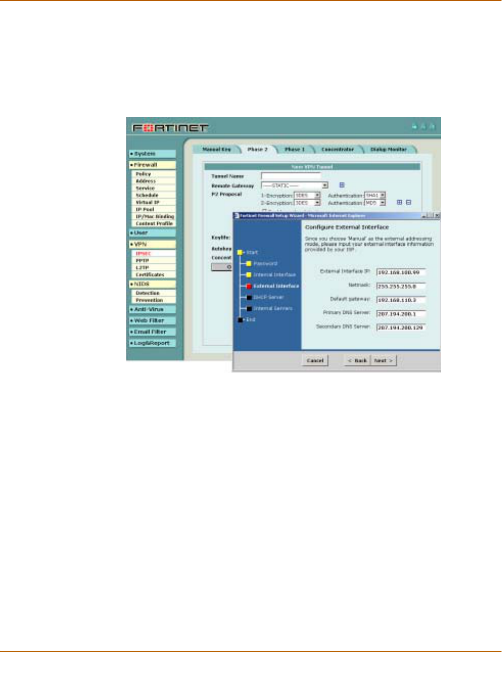
Figure 1: The FortiWiFi web-based manager and setup wizard
Command line interface
You can access the FortiWiFi command line interface (CLI) by connecting a
management computer serial port to the FortiWiFi RS-232 serial console connector.
You can also use Telnet or a secure SSH connection to connect to the CLI from any
network that is connected to the FortiWiFi unit, including the Internet.
The CLI supports the same configuration and monitoring functionality as the
web-based manager. In addition, you can use the CLI for advanced configuration
options that are not available from the web-based manager.
This Installation and Configuration Guide contains information about basic and
advanced CLI commands. For a more complete description about connecting to and
using the FortiWiFi CLI, see the FortiGate CLI Reference Guide.

Introduction Document conventions
FortiWiFi-60 Installation and Configuration Guide 19
Logging and reporting
The FortiWiFi unit supports logging for various categories of traffic and configuration
changes. You can configure logging to:
• report traffic that connects to the firewall,
• report network services used,
• report traffic that was permitted by firewall policies,
• report traffic that was denied by firewall policies,
• report events such as configuration changes and other management events, IPSec
tunnel negotiation, virus detection, attacks, and web page blocking,
• report attacks detected by the NIDS,
• send alert email to system administrators to report virus incidents, intrusions, and
firewall or VPN events or violations.
Logs can be sent to a remote syslog server or a WebTrends NetIQ Security Reporting
Center and Firewall Suite server using the WebTrends enhanced log format. Some
models can also save logs to an optional internal hard drive. If a hard drive is not
installed, you can configure most FortiWiFi units to log the most recent events and
attacks detected by the NIDS to the system memory.
Document conventions
This guide uses the following conventions to describe CLI command syntax.
• angle brackets < > to indicate variable keywords
For example:
execute restore config <filename_str>
You enter restore config myfile.bak
<xxx_str> indicates an ASCII string variable keyword.
<xxx_integer> indicates an integer variable keyword.
<xxx_ip> indicates an IP address variable keyword.
• vertical bar and curly brackets {|} to separate alternative, mutually exclusive
required keywords
For example:
set system opmode {nat | transparent}
You can enter set system opmode nat or set system opmode
transparent
• square brackets [ ] to indicate that a keyword is optional
For example:
get firewall ipmacbinding [dhcpipmac]
You can enter get firewall ipmacbinding or
get firewall ipmacbinding dhcpipmac

20 Fortinet Inc.
Fortinet documentation Introduction
Fortinet documentation
Information about FortiGate and FortiWiFi products is available from the following
User Manual volumes:
• Volume 1: FortiWiFi-60 Installation and Configuration Guide
Describes installation and basic configuration for the FortiWiFi unit. Also describes
how to use FortiWiFi firewall policies to control traffic flow through the FortiWiFi
unit and how to use firewall policies to apply antivirus protection, web content
filtering, and email filtering to HTTP, FTP, and email content passing through the
FortiWiFi unit.
• Volume 2: FortiGate VPN Guide
Contains in-depth information about FortiGate IPSec VPN using certificates, pre-
shared keys and manual keys for encryption. Also contains basic configuration
information for the Fortinet Remote VPN Client, detailed configuration information
for FortiGate PPTP and L2TP VPN, and VPN configuration examples.
• Volume 3: FortiGate Content Protection Guide
Describes how to configure antivirus protection, web content filtering, and email
filtering to protect content as it passes through the FortiGate unit.
• Volume 4: FortiGate NIDS Guide
Describes how to configure the FortiGate NIDS to detect and protect the FortiGate
unit from network-based attacks.
• Volume 5: FortiGate Logging and Message Reference Guide
Describes how to configure FortiGate logging and alert email. Also contains the
FortiGate log message reference.
• Volume 6: FortiGate CLI Reference Guide
Describes the FortiGate CLI and contains a reference to all FortiGate CLI
commands.
The FortiWiFi online help also contains procedures for using the FortiWiFi web-based
manager to configure and manage the FortiWiFi unit.
Comments on Fortinet technical documentation
You can send information about errors or omissions in this document, or any Fortinet
technical documentation, to techdoc@fortinet.com.

Introduction Customer service and technical support
FortiWiFi-60 Installation and Configuration Guide 21
Customer service and technical support
For antivirus and attack definition updates, firmware updates, updated product
documentation, technical support information, and other resources, please visit the
Fortinet technical support web site at http://support.fortinet.com.
You can also register FortiWiFi Antivirus Firewalls from http://support.fortinet.com and
change your registration information at any time.
Fortinet email support is available from the following addresses:
For information on Fortinet telephone support, see http://support.fortinet.com.
When requesting technical support, please provide the following information:
• Your name
• Company name
•Location
• Email address
• Telephone number
• FortiWiFi unit serial number
• FortiWiFi model
• FortiWiFi FortiOS firmware version
• Detailed description of the problem
amer_support@fortinet.com For customers in the United States, Canada, Mexico, Latin
America and South America.
apac_support@fortinet.com For customers in Japan, Korea, China, Hong Kong, Singapore,
Malaysia, all other Asian countries, and Australia.
eu_support@fortinet.com For customers in the United Kingdom, Scandinavia, Mainland
Europe, Africa, and the Middle East.

22 Fortinet Inc.
Customer service and technical support Introduction

FortiWiFi-60 Installation and Configuration Guide Version 2.50
FortiWiFi-60 Installation and Configuration Guide 23
Getting started
This chapter describes unpacking, setting up, and powering on a FortiWiFi Antivirus
Firewall unit. When you have completed the procedures in this chapter, you can
proceed to one of the following:
• If you are going to operate the FortiWiFi unit in NAT/Route mode, go to “NAT/Route
mode installation” on page 41.
• If you are going to operate the FortiWiFi unit in Transparent mode, go to
“Transparent mode installation” on page 59.
This chapter describes:
•Warnings
•Package contents
•Mounting
•Powering on
•Connecting to the web-based manager
•Connecting to the command line interface (CLI)
•Factory default FortiWiFi configuration settings
•Planning the FortiWiFi configuration
•FortiGate model maximum values matrix
•Next steps
Warnings
!Caution: To comply with FCC radio frequency (RF) exposure limits, dipole antennas should be
located at a minimum of 7.9 inches (20 cm) or more from the body of all persons.
!Caution: Do not operate a wireless network device near unshielded blasting caps or in an
explosive environment unless the device has been modified to be especially qualified for such
use.
24 Fortinet Inc.
Package contents Getting started
Package contents
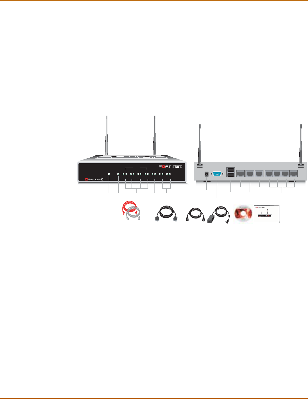
The FortiWiFi-60 package contains the following items:
• FortiWiFi-60 Antivirus Firewall
• one orange crossover ethernet cable
• one gray regular ethernet cable
• one null modem cable
• FortiWiFi-60 Quick Start Guide
• CD containing the FortiGate and FortiWiFi user documentation
• one power cable and AC adapter
Figure 2: FortiWiFi-60 package contents
Mounting
The FortiWiFi-60 unit can be installed on any stable surface. Make sure that the
appliance has at least 1.5 in. (3.75 cm) of clearance on each side to allow for
adequate air flow and cooling.
Dimensions
• 8.63 x 6.13 x 1.38 in. (21.9 x 15.6 x 3.5 cm)
Weight
• 1.5 lb. (0.68 kg)
Power requirements
• DC input voltage: 12 V
• DC input current: 3 A
Null-Modem Cable
(RS-232)
Ethernet Cables:
Orange - Crossover
Grey - Straight-through
Power Cable Power Supply
FortiWiFi-60
QuickStart Guide
Copyright 2003 Fortinet Incorporated. All rights reserved.
Trademarks
Products mentioned in this document are trademarks.
INTERNAL
DMZ4321
LINK 100 LINK 100 LINK 100 LINK 100 LINK 100 LINK 100 LINK 100
WAN1 WA N2
PWR WLAN
Power
LED
WLAN
LED
WAN 1,2
Interface
DMZ
Interface
Internal
Interface
Front
Internal Interface,
switch connectors
1,2,3,4
Back
1234
Console USB WAN2 WA N1 DMZ
DC+12V
Internal
Power
Connection
RS-232 Serial
Connection
USB
WAN2 DMZ
WAN1
Documentation
INTERNAL
DMZ4321
LINK 100 LINK 100 LINK 100 LINK 100 LINK 100 LINK 100 LINK 100
WAN1 WAN2
PWR WLAN

Getting started Powering on
FortiWiFi-60 Installation and Configuration Guide 25
Environmental specifications
• Operating temperature: 32 to 104°F (0 to 40°C)
• Storage temperature: -13 to 158°F (-25 to 70°C)
• Humidity: 5 to 95% non-condensing
Wireless Connectivity
• Antenna type: Dual external fixed antenna
• Antenna range: 802.11b/g:2.4GHz
• Antenna Gain: 5dBi
Basic WiFi installation guidelines
Because the FortiWiFi-60 is a radio device, it is susceptible to common causes of
interference that can reduce throughput and range. Follow these basic guidelines to
ensure the best possible performance:
• Install the access point in an area where large steel structures such as shelving
units, bookcases, and filing cabinets do not block the radio signals to and from the
access point.
• Install the access point away from microwave ovens. Microwave ovens operate on
the same frequency as the access point and can cause signal interference.
Powering on
To power on the FortiWiFi-60 unit
1Connect the AC adapter to the power connection at the back of the FortiWiFi-60 unit.
2Connect the AC adapter to the power cable.
3Connect the power cable to a power outlet.
The FortiWiFi-60 unit starts. The Power and WAN LEDS light.
Table 1: FortiWiFi-60 LED indicators
LED State Description
Power Green The FortiWiFi unit is powered on.
Off The FortiWiFi unit is powered off.
WAN Green Traffic on WAN link.
Link
(Internal
DMZ
WAN1
WAN2)
Green The correct cable is in use and the connected
equipment has power.
Flashing Green Network activity at this interface.
Off No link established.
100
(Internal
DMZ
WAN1
WAN2)
Green The interface is connected at 100 Mbps.
26 Fortinet Inc.
Connecting to the web-based manager Getting started
Connecting to the web-based manager
Use the following procedure to connect to the web-based manager for the first time.
Configuration changes made with the web-based manager are effective immediately
without resetting the firewall or interrupting service.
To connect to the web-based manager, you need:
• a computer with an ethernet connection,
• Internet Explorer version 4.0 or higher,
• an ethernet cable.
• a crossover cable or an ethernet hub and two ethernet cables.
To connect to the web-based manager
1Set the IP address of the computer with an ethernet connection to the static IP
address 192.168.1.2 and a netmask of 255.255.255.0.
You can also configure the management computer to obtain an IP address
automatically using DHCP. The FortiWiFi DHCP server assigns the management
computer an IP address in the range 192.168.1.1 to 192.168.1.254.
2Using the ethernet cable, connect the internal interface of the FortiWiFi unit to the
computer ethernet connection.
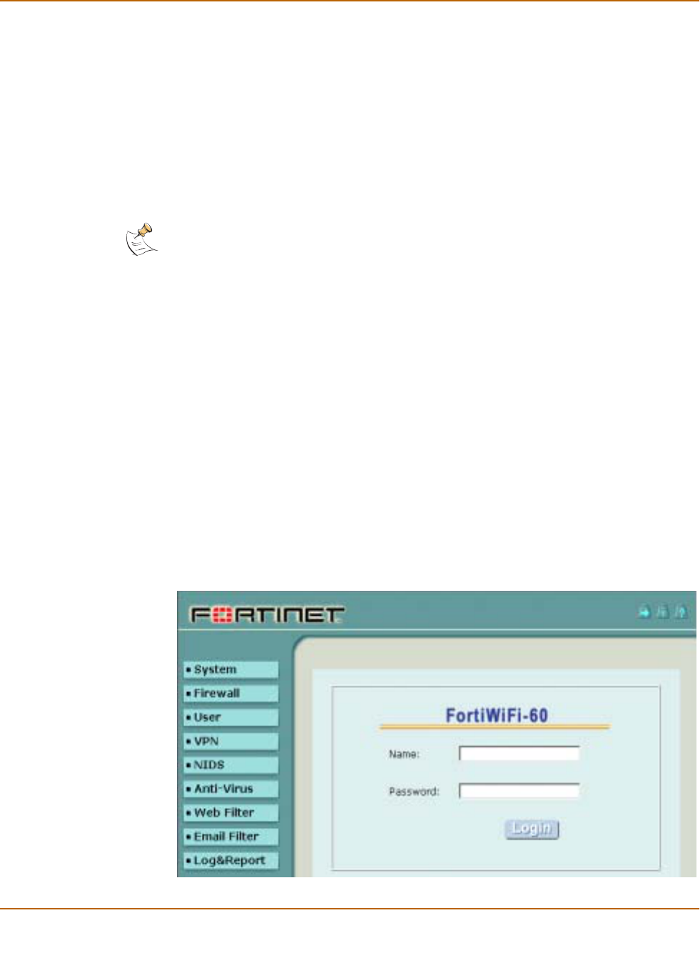
3Start Internet Explorer and browse to the address https://192.168.1.99 (remember to
include the “s” in https://).
The FortiWiFi login is displayed.
4Type admin in the Name field and select Login.
The Register Now window is displayed. Use the information in this window to register
your FortiWiFi unit so that Fortinet can contact you for firmware updates. You must
also register to receive updates to the FortiWiFi virus and attack definitions.
Figure 3: FortiWiFi login
Note: You can use the web-based manager with recent versions of most popular web browsers.
The web-based manager is fully supported for Internet Explorer version 4.0 or higher.

Getting started Connecting to the command line interface (CLI)
FortiWiFi-60 Installation and Configuration Guide 27
Connecting to the command line interface (CLI)
As an alternative to the web-based manager, you can install and configure the
FortiWiFi unit using the CLI. Configuration changes made with the CLI are effective
immediately without resetting the firewall or interrupting service.
To connect to the FortiWiFi CLI, you need:
• a computer with an available communications port,
• the null modem cable included in your FortiWiFi package,
• terminal emulation software such as HyperTerminal for Windows.
To connect to the CLI
1Connect the null modem cable to the communications port of your computer and to
the FortiWiFi Console port.
2Make sure that the FortiWiFi unit is powered on.
3Start HyperTerminal, enter a name for the connection, and select OK.
4Configure HyperTerminal to connect directly to the communications port on the
computer to which you have connected the null modem cable and select OK.
5Select the following port settings and select OK.
6Press Enter to connect to the FortiWiFi CLI.
The following prompt is displayed:
FortiWiFi-60 login:
7Type admin and press Enter twice.
The following prompt is displayed:
Type ? for a list of commands.
For information about how to use the CLI, see the FortiGate CLI Reference Guide.
Note: The following procedure describes how to connect to the CLI using Windows
HyperTerminal software. You can use any terminal emulation program.
Bits per second 9600
Data bits 8
Parity None
Stop bits 1
Flow control None

28 Fortinet Inc.
Factory default FortiWiFi configuration settings Getting started
Factory default FortiWiFi configuration settings
The FortiWiFi unit is shipped with a factory default configuration. The default
configuration allows you to connect to and use the FortiWiFi web-based manager to
configure the FortiWiFi unit onto the network. To configure the FortiWiFi unit onto the
network you add an administrator password, change network interface IP addresses,
add DNS server IP addresses, and configure routing, if required.
If you plan to operate the FortiWiFi unit in Transparent mode, you can switch to
Transparent mode from the factory default configuration and then configure the
FortiWiFi unit onto the network in Transparent mode.
Once the network configuration is complete, you can perform additional configuration
tasks such as setting system time, configuring virus and attack definition updates, and
registering the FortiWiFi unit.
The factory default firewall configuration includes a single network address translation
(NAT) policy that allows users on your internal network to connect to the external
network, and stops users on the external network from connecting to the internal
network. You can add more policies to provide more control of the network traffic
passing through the FortiWiFi unit.
The factory default content profiles can be used to apply different levels of antivirus
protection, web content filtering, and email filtering to the network traffic that is
controlled by firewall policies.
•Factory default DHCP configuration
•Factory default NAT/Route mode network configuration
•Factory default Transparent mode network configuration
•Factory default firewall configuration
•Factory default content profiles
Factory default DHCP configuration
When the FortiWiFi unit is first powered on, the WAN1 interface is configured to
receive its IP address by connecting to a DHCP server. If your ISP provides IP
addresses using DHCP, no other configuration is required for this interface.
The FortiWiFi unit can also function as a DHCP server for your internal network. You
can configure the TCP/IP settings of the computers on your internal network to obtain
an IP address automatically from the FortiWiFi unit DHCP server. For more
information about the FortiWiFi DHCP server, see “Configuring DHCP services” on
page 126.

Getting started Factory default FortiWiFi configuration settings
FortiWiFi-60 Installation and Configuration Guide 29
Factory default NAT/Route mode network configuration
When the FortiWiFi unit is first powered on, it is running in NAT/Route mode and has
the basic network configuration listed in Table 4. This configuration allows you to
connect to the FortiWiFi unit web-based manager and establish the configuration
required to connect the FortiWiFi unit to the network. In Table 4 HTTPS management
access means you can connect to the web-based manager using this interface. Ping
management access means this interface responds to ping requests.
Table 2: FortiWiFi Internal interface DHCP Server default configuration
Enable DHCP ;
Starting IP 192.168.1.101
Ending IP 192.168.1.200
Netmask 255.255.255.0
Lease Duration 7 days
Default Route 192.168.1.99
DNS IP 192.168.1.99
WINS IP 192.168.1.99
Table 3: FortiWiFi WLAN interface DHCP Server default configuration
Enable DHCP ;
Starting IP 192.168.2.101
Ending IP 192.168.2.200
Netmask 255.255.255.0
Lease Duration 7 days
Default Route 192.168.2.99
DNS IP 192.168.2.99
WINS IP 192.168.2.99
Table 4: Factory default NAT/Route mode network configuration
Administrator
account
User name: admin
Password: (none)
Internal interface
IP: 192.168.1.99
Netmask: 255.255.255.0
Management Access: HTTPS, Ping
WAN1 interface Addressing Mode: DHCP
Management Access: Ping
WAN2 interface
IP: 192.168.101.99
Netmask: 255.255.255.0
Management Access: Ping

30 Fortinet Inc.
Factory default FortiWiFi configuration settings Getting started
Factory default Transparent mode network configuration
If you switch the FortiWiFi unit to Transparent mode, it has the default network
configuration listed in Table 5.
DMZ interface
IP: 10.10.10.1
Netmask: 255.255.255.0
Management Access: HTTPS, Ping
WLAN interface
IP: 192.168.100.99
Netmask: 255.255.255.0
Management Access:
Geography: World
Channel: 5
Security: none
Key: none
SSID: Fortinet
Table 4: Factory default NAT/Route mode network configuration (Continued)
Table 5: Factory default Transparent mode network configuration
Administrator
account User name: admin
Password: (none)
Management IP IP: 10.10.10.1
Netmask: 255.255.255.0
DNS Primary DNS Server: 207.194.200.1
Secondary DNS Server: 207.194.200.129
Management access
Internal HTTPS, Ping
WAN1 Ping
WAN2 Ping
DMZ HTTPS, Ping
Wireless
Geography World
Channel 5
Security None
Key None
SSID fortinet

Getting started Factory default FortiWiFi configuration settings
FortiWiFi-60 Installation and Configuration Guide 31
Factory default firewall configuration
The factory default firewall configuration is the same in NAT/Route and Transparent
mode.
Table 6: Factory default firewall configuration
Internal
Address Internal_All IP: 0.0.0.0 Represents all of the IP addresses on the internal
network.
Mask: 0.0.0.0
WAN1
Address WAN1_All IP: 0.0.0.0 Represents all of the IP addresses on the network
connected to the WAN1 interface.
Mask: 0.0.0.0
WAN2
Address WAN2_All IP: 0.0.0.0 Represents all of the IP addresses on the network
connected to the WAN2 interface.
Mask: 0.0.0.0
WLAN
Address WLAN_All IP: 0.0.0.0 Represents all of the IP addresses on the network
connected to the WLAN interface.
Mask: 0.0.0.0
DMZ
Address DMZ_All IP: 0.0.0.0 Represents all of the IP addresses on the network
connected to the DMZ interface.
Mask: 0.0.0.0
Recurring
Schedule Always The schedule is valid at all times. This means that
the firewall policy is valid at all times.
Firewall
Policy Internal->WAN1 Firewall policy for connections from the internal
network to the WAN1 network.
Source Internal_All The policy source address. Internal_All means that
the policy accepts connections from any internal IP
address.
Destination WAN1_All The policy destination address. WAN1_All means
that the policy accepts connections with a
destination address to any IP address on the
external (WAN1) network.
Firewall
Policy Internal->WAN2 Firewall policy for connections from the internal
network to the WAN2 network.
Source Internal_All The policy source address. Internal_All means that
the policy accepts connections from any internal IP
address.
Destination WAN2_All The policy destination address. WAN2_All means
that the policy accepts connections with a
destination address to any IP address on the
external (WAN2) network.
Firewall
Policy WLAN->WAN1 Firewall policy for connections from the WLAN
network to the WAN1 network.
Source WLAN_All The policy source address. Internal_All means that
the policy accepts connections from any WLAN IP
address.
Destination WAN1_All The policy destination address. WAN1_All means
that the policy accepts connections from the
wireless network with a destination address to any
IP address on the external (WAN1) network.

32 Fortinet Inc.
Factory default FortiWiFi configuration settings Getting started
Firewall
Policy WLAN->WAN2 Firewall policy for connections from the WLAN
network to the WAN2 network.
Source WLAN_All The policy source address. Internal_All means that
the policy accepts connections from any WLAN IP
address.
Destination WAN2_All The policy destination address. WAN2_All means
that the policy accepts connections from the
wireless network with a destination address to any
IP address on the external (WAN2) network.
General Firewall Policy Options
Schedule Always The policy schedule. Always means that the policy
is valid at any time.
Service ANY The policy service. ANY means that this policy
processes connections for all services.
Action ACCEPT The policy action. ACCEPT means that the policy
allows connections.
;NAT NAT is selected for the NAT/Route mode default
policy so that the policy applies network address
translation to the traffic processed by the policy.
NAT is not available for Transparent mode policies.
Traffic Shaping Traffic shaping is not selected. The policy does not
apply traffic shaping to the traffic controlled by the
policy. You can select this option to control the
maximum or minimum amount of bandwidth
available to traffic processed by the policy.
Authentication Authentication is not selected. Users do not have to
authenticate with the firewall before connecting to
their destination address. You can configure user
groups and select this option to require users to
authenticate with the firewall before they can
connect through the firewall.
;Antivirus & Web Filter Antivirus & Web Filter is selected.
Content
Profile Scan The scan content profile is selected. The policy
scans all HTTP, FTP, SMTP, POP3, and IMAP
traffic for viruses. See “Scan content profile” on
page 34 for more information about the scan
content profile. You can select one of the other
content profiles to apply different levels of content
protection to traffic processed by this policy.
Log Traffic Log Traffic is not selected. This policy does not
record messages to the traffic log for the traffic
processed by this policy. You can configure
FortiWiFi logging and select Log Traffic to record all
connections through the firewall that are accepted
by this policy.
Table 6: Factory default firewall configuration (Continued)

Getting started Factory default FortiWiFi configuration settings
FortiWiFi-60 Installation and Configuration Guide 33
Factory default content profiles
You can use content profiles to apply different protection settings for content traffic
that is controlled by firewall policies. You can use content profiles for:
• Antivirus protection of HTTP, FTP, IMAP, POP3, and SMTP network traffic
• Web content filtering for HTTP network traffic
• Email filtering for IMAP and POP3 network traffic
• Oversized file and email blocking for HTTP, FTP, POP3, SMTP, and IMAP network
traffic
• Passing fragmented emails in IMAP, POP3, and SMTP email traffic
Using content profiles, you can build protection configurations that can be applied to
different types of firewall policies. This allows you to customize types and levels of
protection for different firewall policies.
For example, while traffic between internal and external addresses might need strict
protection, traffic between trusted internal addresses might need moderate protection.
You can configure policies for different traffic services to use the same or different
content profiles.
Content profiles can be added to NAT/Route mode and Transparent mode policies.
Strict content profile
Use the strict content profile to apply maximum content protection to HTTP, FTP,
IMAP, POP3, and SMTP content traffic. You do not need to use the strict content
profile under normal circumstances, but it is available if you have extreme problems
with viruses and require maximum content screening protection.
Table 7: Strict content profile
Options HTTP FTP IMAP POP3 SMTP
Antivirus Scan ;;;;;
File Block ;;;;;
Web URL Block ;
Web Content Block ;
Web Script Filter ;
Web Exempt List ;
Email Block List ;;
Email Exempt List ;;
Email Content Block ;;
Oversized File/Email Block block block block block block
Pass Fragmented Emails

34 Fortinet Inc.
Factory default FortiWiFi configuration settings Getting started
Scan content profile
Use the scan content profile to apply antivirus scanning to HTTP, FTP, IMAP, POP3,
and SMTP content traffic.
Web content profile
Use the web content profile to apply antivirus scanning and web content blocking to
HTTP content traffic. You can add this content profile to firewall policies that control
HTTP traffic.
Table 8: Scan content profile
Options HTTP FTP IMAP POP3 SMTP
Antivirus Scan ;;;;;
File Block
Web URL Block
Web Content Block
Web Script Filter
Web Exempt List
Email Block List
Email Exempt List
Email Content Block
Oversized File/Email Block pass pass pass pass pass
Pass Fragmented Emails
Table 9: Web content profile
Options HTTP FTP IMAP POP3 SMTP
Antivirus Scan ;
File Block
Web URL Block ;
Web Content Block ;
Web Script Filter
Web Exempt List
Email Block List
Email Exempt List
Email Content Block
Oversized File/Email Block pass pass pass pass pass
Pass Fragmented Emails

Getting started Planning the FortiWiFi configuration
FortiWiFi-60 Installation and Configuration Guide 35
Unfiltered content profile
Use the unfiltered content profile if you do not want to apply content protection to
traffic. You can add this content profile to firewall policies for connections between
highly trusted or highly secure networks where content does not need to be protected.
Planning the FortiWiFi configuration
Before you configure the FortiWiFi unit, you need to plan how to integrate the unit into
the network. Among other things, you must decide whether you want the unit to be
visible to the network, which firewall functions you want it to provide, and how you
want it to control the traffic flowing between its interfaces.
Your configuration plan depends on the operating mode that you select. The FortiWiFi
unit can be configured in one of two modes: NAT/Route mode (the default) or
Transparent mode.
NAT/Route mode
In NAT/Route mode, the unit is visible to the network. Like a router, all its interfaces
are on different subnets. The following interfaces are available in NAT/Route mode:
• WAN1 is the default interface to the external network (usually the Internet).
• WAN2 is the redundant interface to the external network.
• Internal is the interface to the internal network.
• DMZ is the interface to the DMZ network.
• WLAN is the interface to the wireless LAN network.
You must configure routing to support the redundant WAN1 and WAN2 internet
connections. Routing can be used to automatically redirect connections from an
interface if its connection to the external network fails.
Table 10: Unfiltered content profile
Options HTTP FTP IMAP POP3 SMTP
Antivirus Scan
File Block
Web URL Block
Web Content Block
Web Script Filter
Web Exempt List ;
Email Block List
Email Exempt List ;;
Email Content Block
Oversized File/Email Block pass pass pass pass pass
Pass Fragmented Emails ;;;
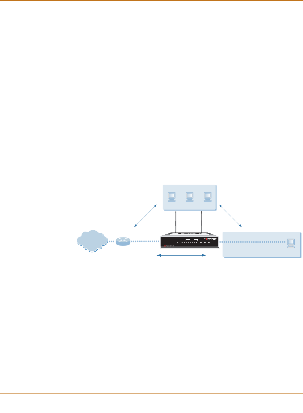
36 Fortinet Inc.
Planning the FortiWiFi configuration Getting started
You can add security policies to control whether communications through the
FortiWiFi unit operate in NAT or Route mode. Security policies control the flow of
traffic based on the source address, destination address, and service of each packet.
In NAT mode, the FortiWiFi unit performs network address translation before it sends
the packet to the destination network. In Route mode, there is no translation.
By default, the FortiWiFi unit has a NAT mode security policy that allows users on the
internal network to securely download content from the external network. No other
traffic is possible until you have configured further security policies.
You typically use NAT/Route mode when the FortiWiFi unit is operating as a gateway
between private and public networks. In this configuration, you would create NAT
mode policies to control traffic flowing between the internal, private network and the
external, public network (usually the Internet).
In addition, you can use NAT/Route mode when the FortiWiFi-60 is operating as a
gateway for your wireless network. In this configuration you would create NAT mode
policies to control traffic flowing between the wireless network and the Internet as well
as between the wireless network and other networks (such as the internal or DMZ
networks).
If you have multiple internal networks, such as a DMZ network in addition to the
internal, private network, you could create route mode policies for traffic flowing
between them.
Figure 4: Example NAT/Route mode network configuration
Transparent mode
In Transparent mode, the FortiWiFi unit is invisible to the network. Similar to a network
bridge, all FortiWiFi interfaces must be on the same subnet. You only have to
configure a management IP address so that you can make configuration changes.
The management IP address is also used for antivirus and attack definition updates.
You typically use the FortiWiFi unit in Transparent mode on a private network behind
an existing firewall or behind a router. The FortiWiFi unit performs firewall functions as
well as antivirus and content scanning but not VPN.
FortiWiFi-60 Unit
in NAT/Route mode
Internal network
Wireless network
Internal
192.168.1.99
WLAN
192.168.40.1
192.168.1.3
192.168.40.4
WAN1
204.23.1.5
NAT mode policies controlling
traffic between internal and
external networks.
NAT mode policies controlling
traffic between WLAN and
external networks.
NAT mode policies controlling
traffic between WLAN and
internal networks.
Internet
INTERNAL
DMZ4321
LINK 100 LINK 100 LINK 100 LINK 100 LINK 100 LINK 100 LINK 100
WAN1 WAN2
PWR WLAN
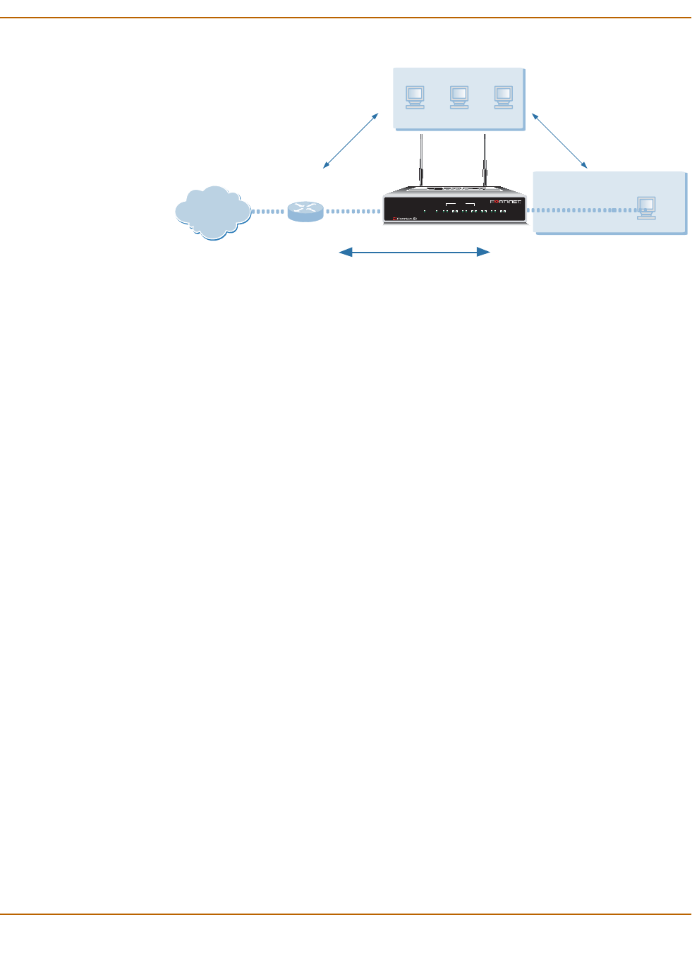
Getting started Planning the FortiWiFi configuration
FortiWiFi-60 Installation and Configuration Guide 37
Figure 5: Example Transparent mode network configuration
You can connect up to four network segments to the FortiWiFi unit to control traffic
between these network segments.
• WAN1 can connect to the external firewall or router.
• Internal can connect to the internal network.
• DMZ and WAN2 can connect to other network segments.
• WLAN connects to the wireless network.
In Transparent mode the wireless network is on the same subnet as the private
network. Using Transparent mode firewall policies you can control the flow of traffic
from the wireless network segment to other network segments.
Configuration options
Once you have selected Transparent or NAT/Route mode operation, you can
complete the configuration plan and begin to configure the FortiWiFi unit.
You can use the web-based manager setup wizard or the command line interface
(CLI) for the basic configuration of the FortiWiFi unit.
Setup wizard
If you are configuring the FortiWiFi unit to operate in NAT/Route mode (the default),
the setup wizard prompts you to add the administration password and the internal
interface address. The setup wizard also prompts you to choose either a manual
(static) or a dynamic (DHCP or PPPoE) address for the WAN1 interface. Using the
wizard, you can also add DNS server IP addresses and a default route for the WAN1
interface.
In NAT/Route mode you can also change the configuration of the FortiWiFi DHCP
server to supply IP addresses for the computers on your internal network. You can
also configure the FortiWiFi to allow Internet access to your internal Web, FTP, or
email servers.
Using the web-based manager you can also add a DHCP server configuration to the
WLAN interface to supply IP addresses to the computers on your wireless network.
You can also add firewall policies to allow Internet access from the wireless network.
FortiWiFi-60 Unit
in Transparent mode
10.10.10.1
Management IP
10.10.10.3
WAN1
WLAN
Internal
10.10.10.2
Transparent mode policies
controlling traffic between
internal and external networks.
204.23.1.5
(firewall, router)
Gateway to
public network Internal network
INTERNAL
DMZ4321
LINK 100 LINK 100 LINK 100 LINK 100 LINK 100 LINK 100 LINK 100
WAN1 WAN 2
PWR WLAN
Wireless network
10.10.10.5 Transparent mode policies controlling
traffic between WLAN and
internal networks.
Transperent mode policies controlling
traffic between WLAN and
internal networks.
Internet

38 Fortinet Inc.
Planning the FortiWiFi configuration Getting started
If you are configuring the FortiWiFi unit to operate in Transparent mode, you can
switch to Transparent mode from the web-based manager and then use the setup
wizard to add the administration password, the management IP address and gateway,
and the DNS server addresses.
CLI
If you are configuring the FortiWiFi unit to operate in NAT/Route mode, you can add
the administration password and all interface addresses. You can also use the CLI to
configure the WAN1 interface for either a manual (static) or a dynamic (DHCP or
PPPoE) address. Using the CLI, you can also add DNS server IP addresses and a
default route for the WAN1 interface.
In NAT/Route mode you can also change the configuration of the FortiWiFi DHCP
server to supply IP addresses for the computers on your internal network.
Using the CLI you can also add a DHCP server configuration to the WLAN interface to
supply IP addresses to the computers on your wireless network. You can also add
firewall policies to allow Internet access from the wireless network.
If you are configuring the FortiWiFi unit to operate in Transparent mode, you can use
the CLI to switch to Transparent mode, Then you can add the administration
password, the management IP address and gateway, and the DNS server addresses.

Getting started FortiGate model maximum values matrix
FortiWiFi-60 Installation and Configuration Guide 39
FortiGate model maximum values matrix
Table 11: FortiGate maximum values matrix
FortiGate model
50 60** 100 200 300 400 500 800 1000 3000 3600 4000
Routes 500 500 500 500 500 500 500 500 500 500 500 500
Policy routing
gateways 500 500 500 500 500 500 500 500 500 500 500 500
Administrative
users 500 500 500 500 500 500 500 500 500 500 500 500
VLAN
subinterfaces N/A N/A N/A 4096* 4096* 4096* 4096* 4096* 4096* 4096* 4096* 4096*
Zones N/A N/A N/A 100 100 100 100 100 200 300 500 500
Virtual domains N/AN/AN/A1632646464128512512512
DHCP address
scopes 32 32 32 32 32 32 32 32 32 32 32 32
DHCP reserved
IP/MAC pairs 10 20 30 30 50 50 100 100 200 200 200 200
Firewall policies 200 500 1000 2000 5000 5000 20000 20000 50000 50000 50000 50000
Firewall
addresses 500 500 500 500 3000 3000 6000 6000 10000 10000 10000 10000
Firewall address
groups 500 500 500 500 500 500 500 500 500 500 500 500
Firewall custom
services 500 500 500 500 500 500 500 500 500 500 500 500
Firewall service
groups 500 500 500 500 500 500 500 500 500 500 500 500
Firewall recurring
schedules 256 256 256 256 256 256 256 256 256 256 256 256
Firewall onetime
schedules 256 256 256 256 256 256 256 256 256 256 256 256
Firewall virtual
IPs 500 500 500 500 500 500 500 500 500 500 500 500
Firewall IP pools 50 50 50 50 50 50 50 50 50 50 50 50
IP/MAC binding
table entries 500 500 500 500 500 500 500 500 500 500 500 500
Firewall content
profiles 32 32 32 32 32 32 32 32 32 32 32 32
User names 20 500 1000 1000 1000 1000 1000 1000 1000 1000 1000 1000
Radius servers 666666666666
LDAP servers 666666666666
User groups 100 100 100 100 100 100 100 100 100 100 100 100
Total number of
user group
members
300 300 300 300 300 300 300 300 300 300 300 300
* Includes the number of physical interfaces. **FortiGate-60 and FortiWiFi-60.

40 Fortinet Inc.
Next steps Getting started
Next steps
Now that your FortiWiFi unit is operating, you can proceed to configure it to connect to
networks:
• If you are going to operate the FortiWiFi unit in NAT/Route mode, go to “NAT/Route
mode installation” on page 41.
• If you are going to operate the FortiWiFi unit in Transparent mode, go to
“Transparent mode installation” on page 59.
IPSec remote
gateways
(Phase 1)
20 50 80 200 1500 1500 3000 3000 5000 5000 5000 5000
IPSec VPN
tunnels (Phase 2) 20 50 80 200 1500 1500 3000 3000 5000 5000 5000 5000
IPSec VPN
concentrators 500 500 500 500 500 500 500 500 500 500 500 500
PPTP users 500 500 500 500 500 500 500 500 500 500 500 500
L2TP users 500 500 500 500 500 500 500 500 500 500 500 500
NIDS user-defined
signatures 100 100 100 100 100 100 100 100 100 100 100 100
Antivirus file
block patterns 56 56 56 56 56 56 56 56 56 56 56 56
Web filter and
email filter lists Limit varies depending on available system memory. Fortinet recommends limiting total size of web and
email filter lists to 4 Mbytes or less. If you want to use larger web filter lists, consider using Cerberian web
filtering.
Log setting traffic
filter entries 50 50 50 50 50 50 50 50 50 50 50 50
Table 11: FortiGate maximum values matrix
FortiGate model
50 60** 100 200 300 400 500 800 1000 3000 3600 4000
* Includes the number of physical interfaces. **FortiGate-60 and FortiWiFi-60.

FortiWiFi-60 Installation and Configuration Guide Version 2.50
FortiWiFi-60 Installation and Configuration Guide 41
NAT/Route mode installation
This chapter describes how to install the FortiWiFi unit in NAT/Route mode. To install
the FortiWiFi unit in Transparent mode, see “Transparent mode installation” on
page 59.
This chapter describes:
•Installing the FortiWiFi unit using the default configuration
•Preparing to configure NAT/Route mode
•Using the setup wizard
•Using the command line interface
•Connecting the FortiWiFi unit to your networks
•Configuring your networks
•Completing the configuration
•Configuration example: Multiple connections to the Internet
Installing the FortiWiFi unit using the default configuration
Depending on your requirements, you may be able to deploy the FortiWiFi unit without
changing its factory default configuration. If the factory default settings in Table 12 are
compatible with your requirements, all you need to do is configure your internal
network and then connect the FortiWiFi unit.
Table 12: FortiWiFi unit factory default configuration
Firewall Policies Four NAT policies allow users on the internal network and on the wireless
network to access any Internet service through the WAN1 and WAN2
interfaces. No other traffic is allowed. All web, ftp, and email traffic is
scanned for viruses.
WAN1 and
WAN2
interfaces
Using DHCP, WAN1 and WAN2 get their IP addresses from your ISP. The
FortiWiFi-60 unit also gets DNS server IPs from these interfaces.
DHCP Server on
internal and
wireless
networks
Internal Starting IP: 192.168.1.10, Ending IP: 192.168.1.200,
Default route: 192.168.1.99, DNS server: 192.168.1.99
WLAN Starting IP: 192.168.2.10, Ending IP: 192.168.2.200,
Default route: 192.168.2.99, DNS server: 192.168.2.99
WLAN IP: 192.168.2.99, Channel: 5, SSID: fortinet

42 Fortinet Inc.
Preparing to configure NAT/Route mode NAT/Route mode installation
To use the factory default configuration, follow these steps to install the FortiWiFi unit:
1Configure the TCP/IP settings of the computers on your internal network to obtain an
IP address automatically using DHCP. Refer to your computer documentation for
assistance.
2Turn on DHCP for the computers on your wireless network as well. If required,
configure wireless settings to use channel 5 and SSID fortinet.
3Complete the procedure in the section “Connecting the FortiWiFi unit to your
networks” on page 47.
Changing the default configuration
You can use the procedures in this chapter to change the default configuration. For
example, if your ISP assigns IP addresses using PPPoE instead of DHCP, you only
need to change the configuration of the WAN1 interface. Use the information in the
rest of this chapter to change the default configuration as required.
This chapter also describe how to change your wireless networking channel and
SSID, and how to improve the security of your wireless network by enabling WEP and
entering a WEP key.
Preparing to configure NAT/Route mode
Use Table 13 to gather the information that you need to customize NAT/Route mode
settings.
Table 13: NAT/Route mode settings
Administrator password:
Internal
interface
IP: _____._____._____._____
Netmask: _____._____._____._____
WAN1 interface
IP: _____._____._____._____
Netmask: _____._____._____._____
Default Gateway: _____._____._____._____
Primary DNS Server: _____._____._____._____
Secondary DNS Server: _____._____._____._____
WAN2 interface IP: _____._____._____._____
Netmask: _____._____._____._____

NAT/Route mode installation Preparing to configure NAT/Route mode
FortiWiFi-60 Installation and Configuration Guide 43
Advanced NAT/Route mode settings
Use Table 14 to gather the information that you need to customize advanced FortiWiFi
NAT/Route mode settings.
Internal servers
Web Server: _____._____._____._____
SMTP Server: _____._____._____._____
POP3 Server: _____._____._____._____
IMAP Server: _____._____._____._____
FTP Server: _____._____._____._____
If you provide access from the Internet to a web server, mail server, IMAP
server, or FTP server installed on an internal network, add the IP
addresses of the servers here.
Table 13: NAT/Route mode settings
Table 14: Advanced FortiWiFi NAT/Route mode settings
WAN1 interface
DHCP: If your Internet Service Provider (ISP) supplies you with
an IP address using DHCP, no further information is
required.
PPPoE: User name:
Password:
If your ISP supplies you with an IP address using PPPoE, record your
PPPoE user name and password.
WAN2 interface
DHCP: If your Internet Service Provider (ISP) supplies you with
an IP address using DHCP, no further information is
required.
PPPoE: User name:
Password:
If your ISP supplies you with an IP address using PPPoE, record your
PPPoE user name and password.
DHCP server
Starting IP: _____._____._____._____
Ending IP: _____._____._____._____
Netmask: _____._____._____._____
Default Route: _____._____._____._____
DNS IP: _____._____._____._____
The FortiWiFi unit contains a DHCP server that you can configure to
automatically set the addresses of the computers on your internal network.

44 Fortinet Inc.
Using the setup wizard NAT/Route mode installation
DMZ interface
Use Table 15 to record the IP address and netmask of the FortiWiFi DMZ interface if
you are configuring it during installation.
Wireless settings
Use Table 16 to record the IP address and netmask of the FortiWiFi-60 WLAN
interface if you are configuring it during installation. If you are configuring wireless
networking you should also configure the wireless Service Set ID (SSID) and channel.
See “Wireless configuration” on page 120 for more information.
Using the setup wizard
From the web-based manager, you can use the setup wizard to create the initial
configuration of your FortiWiFi unit. To connect to the web-based manager, see
“Connecting to the web-based manager” on page 26.
Starting the setup wizard
1Select Easy Setup Wizard (the middle button in the upper-right corner of the
web-based manager).
2Use the information that you gathered in Table 13 on page 42 to fill in the wizard fields.
Select the Next button to step through the wizard pages.
3Confirm your configuration settings and then select Finish and Close.
Reconnecting to the web-based manager
If you used the setup wizard to change the IP address of the internal interface, you
must reconnect to the web-based manager using a new IP address. Browse to https://
followed by the new IP address of the internal interface. Otherwise, you can reconnect
to the web-based manager by browsing to https://192.168.1.99.
Table 15: DMZ interface (Optional)
DMZ IP: _____._____._____._____ Netmask: _____._____._____._____
Table 16: Wireless settings (Optional)
WLAN IP: _____._____._____._____ Netmask: _____._____._____._____
Geography: World Americas EMEA Japan Israel Channel:
Security: None WEP Key:
SSID:
Note: If you use the setup wizard to configure internal server settings, the FortiWiFi unit adds
port forwarding virtual IPs and firewall policies for each server. For each server located on your
internal network the FortiWiFi unit adds a WAN1->Internal policy. For each server located on
your DMZ network, the FortiWiFi unit adds a WAN1->DMZ policy.

NAT/Route mode installation Using the command line interface
FortiWiFi-60 Installation and Configuration Guide 45
You have now completed the initial configuration of your FortiWiFi unit, and you can
proceed to “Connecting the FortiWiFi unit to your networks” on page 47.
Using the command line interface
As an alternative to using the setup wizard, you can configure the FortiWiFi unit using
the command line interface (CLI). To connect to the CLI, see “Connecting to the
command line interface (CLI)” on page 27.
Configuring the FortiWiFi unit to operate in NAT/Route mode
Use the information that you gathered in Table 13 on page 42 to complete the
following procedures.
Configuring NAT/Route mode IP addresses
1Log into the CLI if you are not already logged in.
2Set the IP address and netmask of the internal interface to the internal IP address and
netmask that you recorded in Table 13 on page 42. Enter:
set system interface internal mode static ip <IP address>
<netmask>
Example
set system interface internal mode static ip 192.168.1.1
255.255.255.0
3Set the IP address and netmask of the WAN1 interface to the IP address and netmask
that you recorded in Table 13 on page 42.
To set the manual IP address and netmask, enter:
set system interface wan1 mode static ip <IP address> <netmask>
Example
set system interface wan1 mode
static
ip 204.23.1.5 255.255.255.0
To set the WAN1 interface to use DHCP, enter:
set system interface wan1 mode dhcp connection enable
To set the WAN1 interface to use PPPoE, enter:
set system interface wan1 mode pppoe
username
<user name>
password
<password>
connection
enable
Example
set system interface wan1 mode pppoe username user@domain.com
password mypass connection enable

46 Fortinet Inc.
Using the command line interface NAT/Route mode installation
4Optionally set the IP address and netmask of the WAN2 interface to the IP address
and netmask that you recorded in Table 13 on page 42.
To set the manual IP address and netmask, enter:
set system interface wan2 mode static ip <IP address> <netmask>
Example
set system interface wan2 mode
static
ip 34.3.21.35 255.255.255.0
To set the WAN2 interface to use DHCP, enter:
set system interface wan2 mode dhcp connection enable
To set the WAN2 interface to use PPPoE, enter:
set system interface wan2 mode pppoe
username
<user name>
password
<password>
connection
enable
Example
set system interface wan2 mode pppoe username user@domain.com
password mypass connection enable
5Optionally set the IP address and netmask of the DMZ interface to the DMZ IP
address and netmask that you recorded in Table 15 on page 44. Enter:
set system interface dmz mode static ip <IP address> <netmask>
Example
set system interface dmz mode static ip 10.10.10.2
255.255.255.0
6Optionally set the IP address and netmask of the WLAN interface to the WLAN IP
address and netmask that you recorded in Table 16 on page 44. Enter:
set system interface wlan mode static ip <IP address> <netmask>
Example
set system interface wlan mode static ip 192.168.40.1
255.255.255.0
7Optionally set the wireless configuration using the information that you recorded in
Table 16 on page 44. Enter:
set system interface wlan wireless geography {World | Americas
| EMEA | Israel | Japan} channel <channel_number> ssid
<ssid_name> security WEP key <WEP_key>
Example
set system interface wlan wireless geography Americas channel
10 ssid My_SSID security WEP key My_Wep_Key
8Confirm that the addresses are correct. Enter:
get system interface
The CLI lists the IP address, netmask and other settings for each of the FortiWiFi
interfaces.
9Set the primary DNS server IP addresses. Enter
set system dns primary <IP address>
Example
set system dns primary 293.44.75.21

NAT/Route mode installation Connecting the FortiWiFi unit to your networks
FortiWiFi-60 Installation and Configuration Guide 47
10 Optionally, set the secondary DNS server IP addresses. Enter
set system dns secondary <IP address>
Example
set system dns secondary 293.44.75.22
11 Set the default route to the Default Gateway IP address (not required for DHCP and
PPPoE).
set system route number <route_no> dst 0.0.0.0 0.0.0.0 gw1
<gateway_ip>
Example
set system route number 0 dst 0.0.0.0 0.0.0.0 gw1 204.23.1.2
Connecting the FortiWiFi unit to your networks
When you have completed the initial configuration, you can connect the FortiWiFi unit
between your internal network and the Internet.
There are seven 10/100 BaseTX connectors on the back of the FortiWiFi-60 unit:
• Four Internal ports for connecting to your internal network,
• One WAN1 port for connecting to your public switch or router and the Internet,
• One WAN 2 port for connecting to a second public switch or router and the Internet
for a redundant Internet connection,
• One DMZ port for connecting to a DMZ network.
To connect the FortiWiFi unit:
1Connect the Internal interface connectors to PCs and other network devices in your
internal network.
The Internal interface functions as a switch, allowing up to four devices to be
connected to the internal network and the internal interface.
2Connect the WAN1 interface to the Internet.
Connect to the public switch or router provided by your Internet Service Provider. If
you are a DSL or cable subscriber, connect the WAN1 interface to the internal or LAN
connection of your DSL or cable modem.
3Optionally connect the WAN2 interface to the Internet.
Connect to the public switch or router, usually provided by a different Internet Service
Provider. If you are a DSL or cable subscriber, connect the WAN2 interface to the
internal or LAN connection of your DSL or cable modem.
4Optionally, connect the DMZ interface to your DMZ network.
You can use a DMZ network to provide access from the Internet to a web server or
other server without installing the servers on your internal network.
Note: You can also connect the WAN1 and WAN2 interfaces to different Internet connections to
provide a redundant connection to the Internet.
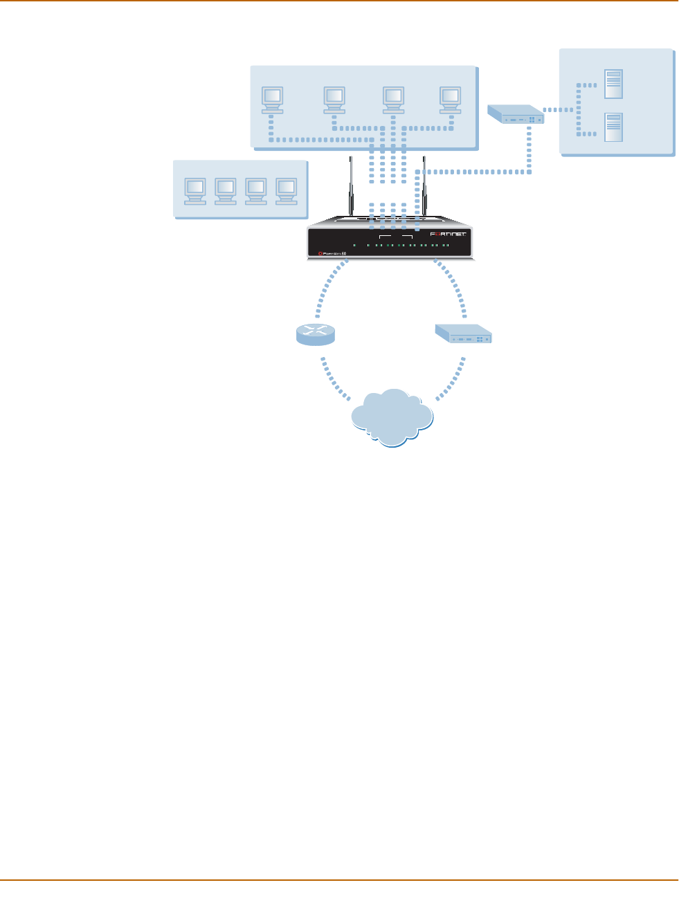
48 Fortinet Inc.
Configuring your networks NAT/Route mode installation
Figure 6: FortiWiFi-60 NAT/Route mode connections
Configuring your networks
If you are operating the FortiWiFi unit in NAT/Route mode, your networks must be
configured to route all Internet traffic to the IP address of the FortiWiFi interface to
which they are connected. For your internal network, change the default gateway
address of all computers and routers connected directly to your internal network to the
IP address of the FortiWiFi internal interface. For the wireless network, change the
default gateway address of all computers on the wireless network to the IP address of
the wlan interface. For your DMZ network, change the default gateway address of all
computers and routers connected directly to your DMZ network to the IP address of
the FortiWiFi DMZ interface. For the external network, route all packets to the
FortiWiFi WAN1 or WAN 2 interface.
If you are using the FortiWiFi unit as the DHCP server for your internal network,
configure the computers on your internal network for DHCP.
Make sure that the connected FortiWiFi unit is functioning properly by connecting to
the Internet from a computer on your internal network. You should be able to connect
to any Internet address.
INTERNAL
DMZ4321
LINK 100 LINK 100 LINK 100 LINK 100 LINK 100 LINK 100 LINK 100
WAN1 WAN 2
PWR WLAN
FortiWiFi-60
DMZ
DMZ Network
Mail Server
Web Server
Internal Network
WAN2WAN1
Internet
Broadband (cable or DSL)
T1
Wireless Network
Internal

NAT/Route mode installation Completing the configuration
FortiWiFi-60 Installation and Configuration Guide 49
Completing the configuration
Use the information in this section to complete the initial configuration of the FortiWiFi
unit.
Configuring the DMZ interface
If you are planning to configure a DMZ network, you might want to change the IP
address of the DMZ interface. Use the following procedure to configure the DMZ
interface using the web-based manager.
1Log into the web-based manager.
2Go to System > Network > Interface.
3For the dmz interface, select Modify .
4Change the IP address and Netmask as required.
5Select Apply.
Configuring the WLAN interface
If you are planning to configure a wireless network, you might want to change the IP
address of the WLAN interface and configure your wireless settings. Use the
information in “Wireless configuration” on page 120 to complete the FortiWiFi-60
wireless configuration.
1Log into the web-based manager.
2Go to System > Network > Interface.
3For the wlan interface, select Modify .
4Change the IP address and Netmask as required.
5Set Geography to your location and select a channel.
6Set Security to WEP (recommended) and enter a WEP key.
7Change the SSID if required.
8Select OK.
Configuring the WAN2 interface
If you are planning to configure a second internet connection using the WAN2
interface, you might want to change the IP address of the WAN2 interface. Use the
following procedure to configure the WAN2 interface using the web-based manager.
1Log into the web-based manager.
2Go to System > Network > Interface.
3For the wan2 interface, select Modify .
4Change the IP address and Netmask as required.
5Select Apply.

50 Fortinet Inc.
Completing the configuration NAT/Route mode installation
Setting the date and time
For effective scheduling and logging, the FortiWiFi system date and time should be
accurate. You can either manually set the system date and time or you can configure
the FortiWiFi unit to automatically keep its time correct by synchronizing with a
Network Time Protocol (NTP) server.
To set the FortiWiFi system date and time, see “Setting system date and time” on
page 143.
Changing antivirus protection
By default, the FortiWiFi unit scans all web and email content for viruses. You can use
the following procedure to change the antivirus configuration. To change the antivirus
configuration:
1Go to Firewall > Policy > Internal->WAN1.
2Select Edit to edit this policy.
3For Anti-Virus & Web Filter you can select a different Content Profile.
See “Factory default content profiles” on page 33 for descriptions of the default
content profiles.
4Select OK to save your changes.
You can also add you own content profiles. See “Adding content profiles” on
page 190.
Registering your FortiWiFi unit
After purchasing and installing a new FortiWiFi unit, you can register the unit by going
to System > Update > Support, or using a web browser to connect to
http://support.fortinet.com and selecting Product Registration.
Registration consists of entering your contact information and the serial numbers of
the FortiWiFi units you or your organization have purchased. Registration is quick and
easy. You can register multiple FortiWiFi units in a single session without re-entering
your contact information.
For more information about registration, see “Registering FortiGate and FortiWiFi
units” on page 104.
Configuring virus and attack definition updates
You can go to System > Update to configure the FortiWiFi unit to automatically check
to see if new versions of the virus definitions and attack definitions are available. If it
finds new versions, the FortiWiFi unit automatically downloads and installs the
updated definitions.
The FortiWiFi unit uses HTTPS on port 8890 to check for updates. The FortiWiFi
WAN1 interface must have a path to the FortiResponse Distribution Network (FDN)
using port 8890.
To configure automatic virus and attack updates, see “Updating antivirus and attack
definitions” on page 93.

NAT/Route mode installation Configuration example: Multiple connections to the Internet
FortiWiFi-60 Installation and Configuration Guide 51
Configuration example: Multiple connections to the Internet
This section describes some basic routing and firewall policy configuration examples
for a FortiWiFi unit with multiple connections to the Internet (see Figure 7). In this
topology, the organization operating the FortiWiFi unit uses two Internet service
providers to connect to the Internet. The FortiWiFi unit is connected to the Internet
using the WAN1 and WAN2 interfaces. The WAN1 interface connects to gateway 1,
operated by ISP1 and the WAN2 interface connects to gateway 2, operated by ISP2.
By adding ping servers to interfaces, and by configuring routing you can control how
traffic uses each Internet connection. With this routing configuration is place you can
proceed to create firewall policies to support multiple internet connections.
This section provides some examples of routing and firewall configurations to
configure the FortiWiFi unit for multiple internet connections. To use the information in
this section you should be familiar with FortiWiFi routing (see “Configuring routing” on
page 122) and FortiWiFi firewall configuration (see “Firewall configuration” on
page 159).
The examples below show how to configure destination-based routing and policy
routing to control different traffic patterns.
•Configuring Ping servers
•Destination based routing examples
•Policy routing examples
•Firewall policy example
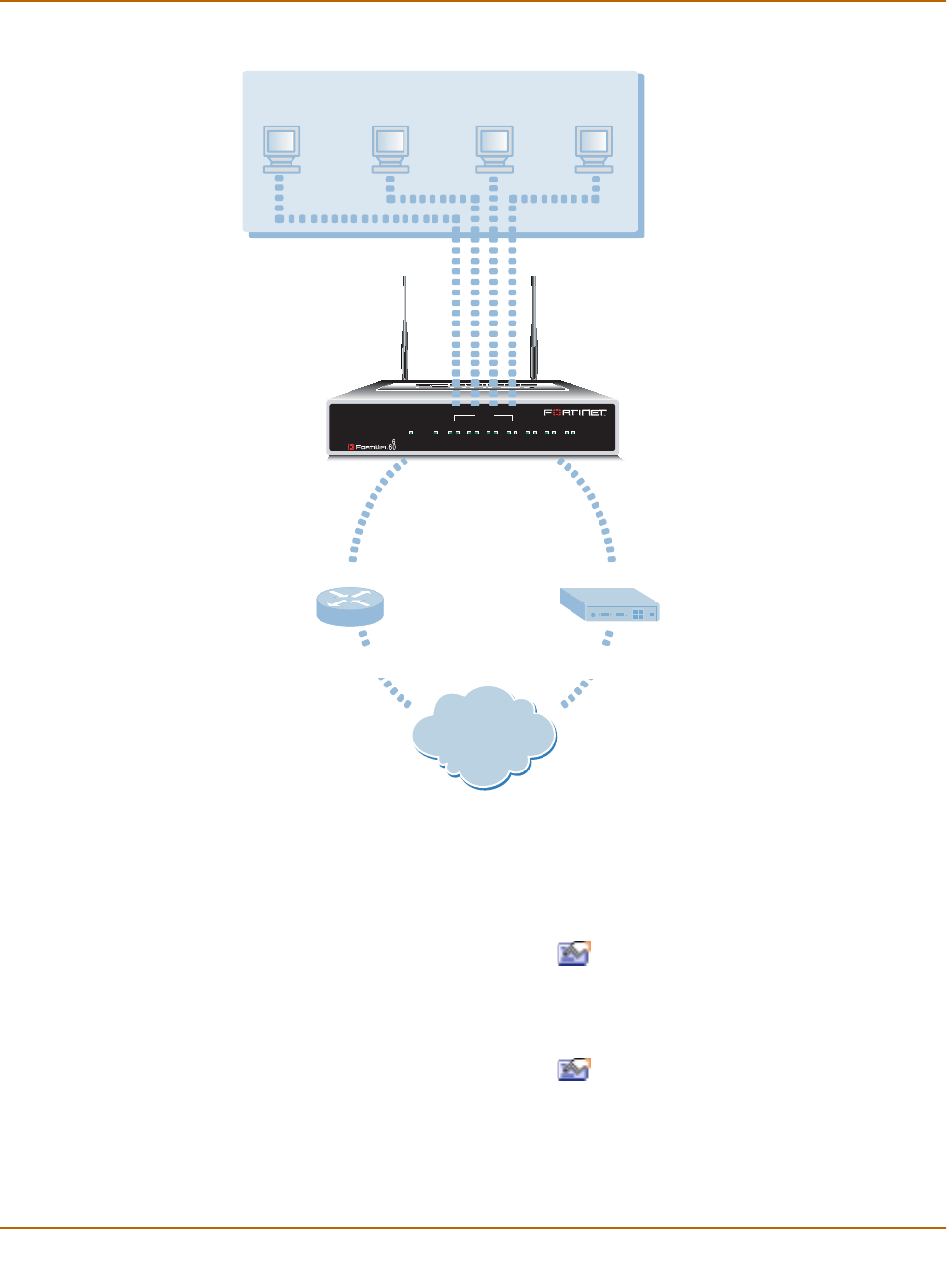
52 Fortinet Inc.
Configuration example: Multiple connections to the Internet NAT/Route mode installation
Figure 7: Example multiple Internet connection configuration
Configuring Ping servers
Use the following procedure to make Gateway 1 the ping server for the WAN1
interface and Gateway 2 the ping server for the WAN2 interface.
1Go to System > Network > Interface.
2For the WAN1 interface, select Modify .
• Ping Server: 1.1.1.1
• Select Enable Ping Server
•Select OK
3For the WAN2 interface, select Modify .
• Ping Server: 2.2.2.1
• Select Enable Ping Server
•Select OK
INTERNAL
DMZ4321
LINK 100 LINK 100 LINK 100 LINK 100 LINK 100 LINK 100 LINK 100
WAN1 WAN2
PWR WLAN
Internal Network
WAN2WAN1
Internal
Internet
External Network #1
100.100.100.0
External Network #2
200.200.200.0
Gateway #1: 1.1.1.1 Gateway #2: 2.2.2.1
ISP1 ISP2
2.2.2.2
1.1.1.2
192.168.1.99
192.168.1.0

NAT/Route mode installation Configuration example: Multiple connections to the Internet
FortiWiFi-60 Installation and Configuration Guide 53
Using the CLI
1Add a ping server to the WAN1 interface.
set system interface wan1 config detectserver 1.1.1.1 gwdetect
enable
2Add a ping server to the WAN2 interface.
set system interface wan2 config detectserver 2.2.2.1 gwdetect
enable
Destination based routing examples
This section describes the following destination-based routing examples:
•Primary and backup links to the Internet
•Load sharing
•Load sharing and primary and secondary connections
Primary and backup links to the Internet
Use the following procedure to add a default destination-based route that directs all
outgoing traffic to Gateway 1. If Gateway 1 fails, all connections are re-directed to
Gateway 2. Gateway 1 is the primary link to the Internet and Gateway 2 is the backup
link.
1Go to System > Network > Routing Table.
2Select New.
• Destination IP: 0.0.0.0
• Mask: 0.0.0.0
• Gateway #1: 1.1.1.1
• Gateway #2: 2.2.2.1
• Device #1: wan1
• Device #2: wan2
•Select OK.
Using the CLI
1Add the route to the routing table.
set system route number 0 dst 0.0.0.0 0.0.0.0 gw1 1.1.1.1
dev1 wan1 gw2 2.2.2.1 dev2 wan2
Table 17: Route for primary and backup links
Destination IP‘ Mask Gateway #1 Device #1 Gateway #2 Device #2
0.0.0.0 0.0.0.0 1.1.1.1 wan1 2.2.2.1 wan2

54 Fortinet Inc.
Configuration example: Multiple connections to the Internet NAT/Route mode installation
Load sharing
You can also configure destination routing to direct traffic through both gateways at
the same time. If users on your internal network connect to the networks of ISP1 and
ISP2, you can add routes for each of these destinations. Each route can include a
backup destination to the network of the other ISP.
The first route directs all traffic destined for the 100.100.100.0 network to gateway 1
with the IP address 1.1.1.1. If this router is down, traffic destined for the 100.100.100.0
network is re-directed to gateway 2 with the IP address 2.2.2.1.
Load sharing and primary and secondary connections
You can combine these routes into a more complete multiple internet connection
configuration. In the topology shown in Figure 7 on page 52, users on the Internal
network would connect to the Internet to access web pages and other Internet
resources. However, they may also connect to services, such as email, provided by
their ISPs. You can combine the routes described in the previous examples to provide
users with a primary and backup connection to the Internet, while at the same time
routing traffic to each ISP network as required.
The routing described below allows a user on the internal network to connect to the
Internet through gateway 1 and ISP1. At the same time, this user can also connect
through the DMZ interface to gateway 2 to access a mail server maintained by ISP2.
Adding the routes using the web-based manager
1Go to System > Network > Routing Table.
2Select New to add the default route for primary and backup links to the Internet.
• Destination IP: 0.0.0.0
• Mask: 0.0.0.0
• Gateway #1: 1.1.1.1
• Gateway #2: 2.2.2.1
• Device #1: wan1
• Device #2: wan2
•Select OK.
Table 18: Load sharing routes
Destination IP‘ Mask Gateway #1 Device #1 Gateway #2 Device #2
100.100.100.0 255.255.255.0 1.1.1.1 wan1 2.2.2.1 wan2
200.200.200.0 255.255.255.0 2.2.2.1 wan2 1.1.1.1 wan1

NAT/Route mode installation Configuration example: Multiple connections to the Internet
FortiWiFi-60 Installation and Configuration Guide 55
3Select New to add a route for connections to the network of ISP1.
• Destination IP: 100.100.100.0
• Mask: 255.255.255.0
• Gateway #1: 1.1.1.1
• Gateway #2: 2.2.2.1
• Device #1: wan1
• Device #2: wan2
4Select New to add a route for connections to the network of ISP2.
• Destination IP: 200.200.200.0
• Mask: 255.255.255.0
• Gateway #1: 2.2.2.1
• Gateway #2: 1.1.1.1
• Device #1: wan1
• Device #2: wan2
•Select OK.
5Change the order of the routes in the routing table to move the default route below the
other two routes.
• For the default route select Move to .
• Type a number in the Move to field to move this route to the bottom of the list.
If there are only 3 routes, type 3.
•Select OK.
Adding the routes using the CLI
1Add the route for connections to the network of ISP2.
set system route number 1 dst 100.100.100.0 255.255.255.0 gw1
1.1.1.1 dev1 wan1 gw2 2.2.2.1 dev2 wan2
1Add the route for connections to the network of ISP1.
set system route number 2 dst 200.200.200.0 255.255.255.0 gw1
2.2.2.1 dev1 wan2 gw2 1.1.1.1 dev2 wan1
2Add the default route for primary and backup links to the Internet.
set system route number 3 dst 0.0.0.0 0.0.0.0 gw1 1.1.1.1
dev1 wan1 gw2 2.2.2.1 dev2 wan2
The routing table should have routes arranged as shown in Table 19.
Table 19: Example combined routing table
Destination IP‘ Mask Gateway #1 Device #1 Gateway #2 Device #2
100.100.100.0 255.255.255.0 1.1.1.1 wan1 2.2.2.1 wan2
200.200.200.0 255.255.255.0 2.2.2.1 wan2 1.1.1.1 wan1
0.0.0.0 0.0.0.0 1.1.1.1 wan1 2.2.2.1 wan2

56 Fortinet Inc.
Configuration example: Multiple connections to the Internet NAT/Route mode installation
Policy routing examples
Policy routing can be added to increase the control you have over how packets are
routed. Policy routing works on top of destination-based routing. This means you
should configure destination-based routing first and then build policy routing on top to
increase the control provided by destination-based routing.
For example, if you have used destination-based routing to configure routing for dual
internet connections, you can use policy routing to apply more control to which traffic
is sent to which destination route. This section describes the following policy routing
examples, based on topology similar to that shown in Figure 7 on page 52.
Differences are noted in each example.
The policy routes described in these examples only work if you have already defined
destination routes similar to those described in the previous section.
•Routing traffic from internal subnets to different external networks
•Routing a service to an external network
For more information about policy routing, see “Policy routing” on page 125.
Routing traffic from internal subnets to different external networks
If the FortiWiFi unit provides internet access for multiple internal subnets, you can use
policy routing to control the route that traffic from each network takes to the Internet.
For example, if the internal network includes the subnets 192.168.10.0 and
192.168.20.0 you can enter the following policy routes:
1Enter the following command to route traffic from the 192.168.10.0 subnet to the
100.100.100.0 external network:
set system route policy 1 src 192.168.10.0 255.255.255.0 dst
100.100.100.0 255.255.255.0 gw 1.1.1.1
2Enter the following command to route traffic from the 192.168.20.0 subnet to the
200.200.200.0 external network:
set system route policy 2 src 192.168.20.0 255.255.255.0 dst
200.200.200.0 255.255.255.0 gw 2.2.2.1
Routing a service to an external network
You can use the following policy routes to direct all HTTP traffic (using port 80) to one
external network and all other traffic to the other external network.
1Enter the following command to route all HTTP traffic using port 80 to the next hop
gateway with IP address 1.1.1.1.
set system route policy 1 src 0.0.0.0 0.0.0.0 dst 0.0.0.0
0.0.0.0 protocol 6 port 80 80 gw 1.1.1.1
2Enter the following command to route all other traffic to the next hop gateway with IP
address 2.2.2.1.
Set system route policy 2 src 0.0.0.0 0.0.0.0 dst 0.0.0.0
0.0.0.0 gw 2.2.2.1

NAT/Route mode installation Configuration example: Multiple connections to the Internet
FortiWiFi-60 Installation and Configuration Guide 57
Firewall policy example
Firewall policies control how traffic flows through the FortiWiFi unit. Once routing for
multiple internet connections has been configured you must create firewall policies to
control which traffic is allowed through the FortiWiFi unit and the interfaces through
which this traffic can connect.
For traffic originating on the Internal network to be able to connect to the Internet
through both Internet connections, you must add redundant policies from the internal
interface to each interface that connects to the Internet. Once these policies have
been added, the routing configuration controls which internet connection is actually
used.
Adding a redundant default policy
Figure 7 on page 52 shows a FortiWiFi unit connected to the Internet using its internal
and DMZ interfaces. The default policy allows all traffic from the internal network to
connect to the Internet through the WAN1 interface. If you add a similar policy to the
internal to WAN2 policy list, this policy will allow all traffic from the internal network to
connect to the Internet through the WAN2 interface. With both of these policies added
to the firewall configuration, the routing configuration will determine which Internet
connection the traffic from the internal network actually uses. For more information
about the default policy, see “Default firewall configuration” on page 160.
To add a redundant default policy
1Go to Firewall > Policy > Int->WAN2.
2Select New.
3Configure the policy to match the default policy.
4Select OK to save your changes.
Adding more firewall policies
In most cases your firewall configuration includes more than just the default policy.
However, the basic premise of creating redundant policies applies even as the firewall
configuration becomes more complex. To configure the FortiWiFi unit to use multiple
Internet connections you must add duplicate policies for connections between the
internal network and both interfaces connected to the Internet. As well, as you add
redundant policies, you must arrange them in both policy lists in the same order.
Source Internal_All
Destination WAN2_All
Schedule Always
Service ANY
Action Accept
NAT Select NAT.

58 Fortinet Inc.
Configuration example: Multiple connections to the Internet NAT/Route mode installation
Restricting access to a single Internet connection
In some cases you might want to limit some traffic to only being able to use one
Internet connection. For example, in the topology shown in Figure 7 on page 52 the
organization might want its mail server to only be able to connect to the SMTP mail
server of ISP1. To do this, you add a single Internal->WAN1 firewall policy for SMTP
connections. Because redundant policies have not been added, SMTP traffic from the
Internet network is always connected to ISP1. If the connection to ISP1 fails the SMTP
connection is not available.

FortiWiFi-60 Installation and Configuration Guide Version 2.50
FortiWiFi-60 Installation and Configuration Guide 59
Transparent mode installation
This chapter describes how to install your FortiWiFi unit in Transparent mode. If you
want to install the FortiWiFi unit in NAT/Route mode, see “NAT/Route mode
installation” on page 41.
This chapter describes:
•Preparing to configure Transparent mode
•Using the setup wizard
•Using the command line interface
•Connecting the FortiWiFi unit to your networks
•Completing the configuration
•Transparent mode configuration examples
Preparing to configure Transparent mode
Use Table 20 to gather the information that you need to customize Transparent mode
settings.
Wireless settings
If you are configuring wireless networking Use Table 21 to record the wireless Service
Set ID (SSID) and channel. See “Wireless configuration” on page 120 for more
information.
Table 20: Transparent mode settings
Administrator Password:
Management IP
IP: _____._____._____._____
Netmask: _____._____._____._____
Default Gateway: _____._____._____._____
The management IP address and netmask must be valid for the network
from which you will manage the FortiWiFi unit. Add a default gateway if the
FortiWiFi unit must connect to a router to reach the management
computer.
DNS Settings Primary DNS Server: _____._____._____._____
Secondary DNS Server: _____._____._____._____

60 Fortinet Inc.
Using the setup wizard Transparent mode installation
Using the setup wizard
From the web-based manager, you can use the setup wizard to create the initial
configuration of your FortiWiFi unit. To connect to the web-based manager, see
“Connecting to the web-based manager” on page 26.
Changing to Transparent mode
The first time that you connect to the FortiWiFi unit, it is configured to run in
NAT/Route mode. To switch to Transparent mode using the web-based manager:
1Go to System > Status.
2Select Change to Transparent Mode.
3Select Transparent in the Operation Mode list.
4Select OK.
The FortiWiFi unit changes to Transparent mode.
To reconnect to the web-based manager, change the IP address of your management
computer to 10.10.10.2. Connect to the internal or DMZ interface and browse to
https:// followed by the Transparent mode management IP address. The default
FortiWiFi Transparent mode management IP address is 10.10.10.1.
Starting the setup wizard
1Select Easy Setup Wizard (the middle button in upper-right corner of the web-based
manager).
2Use the information that you gathered in Table 20 on page 59 to fill in the wizard fields.
Select the Next button to step through the wizard pages.
3Confirm your configuration settings and then select Finish and Close.
Reconnecting to the web-based manager
If you changed the IP address of the management interface while you were using the
setup wizard, you must reconnect to the web-based manager using the new IP
address. Browse to https:// followed by the new IP address of the management
interface. Otherwise, you can reconnect to the web-based manager by browsing to
https://10.10.10.1. If you connect to the management interface through a router, make
sure that you have added a default gateway for that router to the management IP
default gateway field.
Table 21: Wireless settings (Optional)
Geography: World Americas EMEA Japan Israel Channel:
Security: None WEP Key:
SSID:

Transparent mode installation Using the command line interface
FortiWiFi-60 Installation and Configuration Guide 61
Using the command line interface
As an alternative to the setup wizard, you can configure the FortiWiFi unit using the
command line interface (CLI). To connect to the CLI, see “Connecting to the command
line interface (CLI)” on page 27. Use the information that you gathered in Table 20 on
page 59 to complete the following procedures.
Changing to Transparent mode
1Log into the CLI if you are not already logged in.
2Switch to Transparent mode. Enter:
set system opmode transparent
After a few seconds, the login prompt appears.
3Type admin and press Enter.
The following prompt appears:
Type ? for a list of commands.
4Confirm that the FortiWiFi unit has switched to Transparent mode. Enter:
get system status
The CLI displays the status of the FortiWiFi unit. The last line shows the current
operation mode.
Operation mode: Transparent
Configuring the Transparent mode management IP address
1Log into the CLI if you are not already logged in.
2Set the management IP address and netmask to the IP address and netmask that you
recorded in Table 20 on page 59. Enter:
set system management ip <IP address> <netmask>
Example
set system management ip 10.10.10.2 255.255.255.0
3Confirm that the address is correct. Enter:
get system management
The CLI lists the management IP address and netmask.
Configure the Transparent mode default gateway
1Log into the CLI if you are not already logged in.
2Set the default route to the default gateway that you recorded in Table 20 on page 59.
Enter:
set system route number <number> gateway <IP address>
Example
set system route
number 1 gw1
204.23.1.2
You have now completed the initial configuration of the FortiWiFi unit.

62 Fortinet Inc.
Connecting the FortiWiFi unit to your networks Transparent mode installation
Configuring wireless settings
1Log into the CLI if you are not already logged in.
2Set the wireless configuration using the SSID and channel that you recorded in
Table 21 on page 60. Enter:
set system interface wlan wireless geography {World | Americas
| EMEA | Israel | Japan} channel <channel_number> ssid
<ssid_name> security WEP key <WEP_key>
Example
set system interface wlan wireless geography Americas channel
10 ssid My_SSID security WEP key My_Wep_Key
Connecting the FortiWiFi unit to your networks
When you have completed the initial configuration, you can connect the FortiWiFi unit
between your internal network and the Internet using the Internal and WAN1
interfaces. You can also connect networks to the DMZ interface and the WAN2
interface.
There are seven 10/100Base-TX connectors on the FortiWiFi-60:
• Four Internal ports for connecting to your internal network,
• WAN1 for connecting to the Internet,
• DMZ and WAN2 which can be connected to networks.
To connect the FortiWiFi unit running in Transparent mode:
1Connect the Internal interface connectors to PCs and other network devices in your
internal network.
The Internal interface functions as a switch, allowing up to four devices to be
connected to the internal network and the internal interface.
2Connect the WAN1 interface to the Internet.
Connect to the public switch or router provided by your Internet Service Provider. If
you are a DSL or cable subscriber, connect the WAN1 interface to the internal or LAN
connection of your DSL or cable modem.
3Optionally connect the WAN2 and DMZ interfaces to other networks.
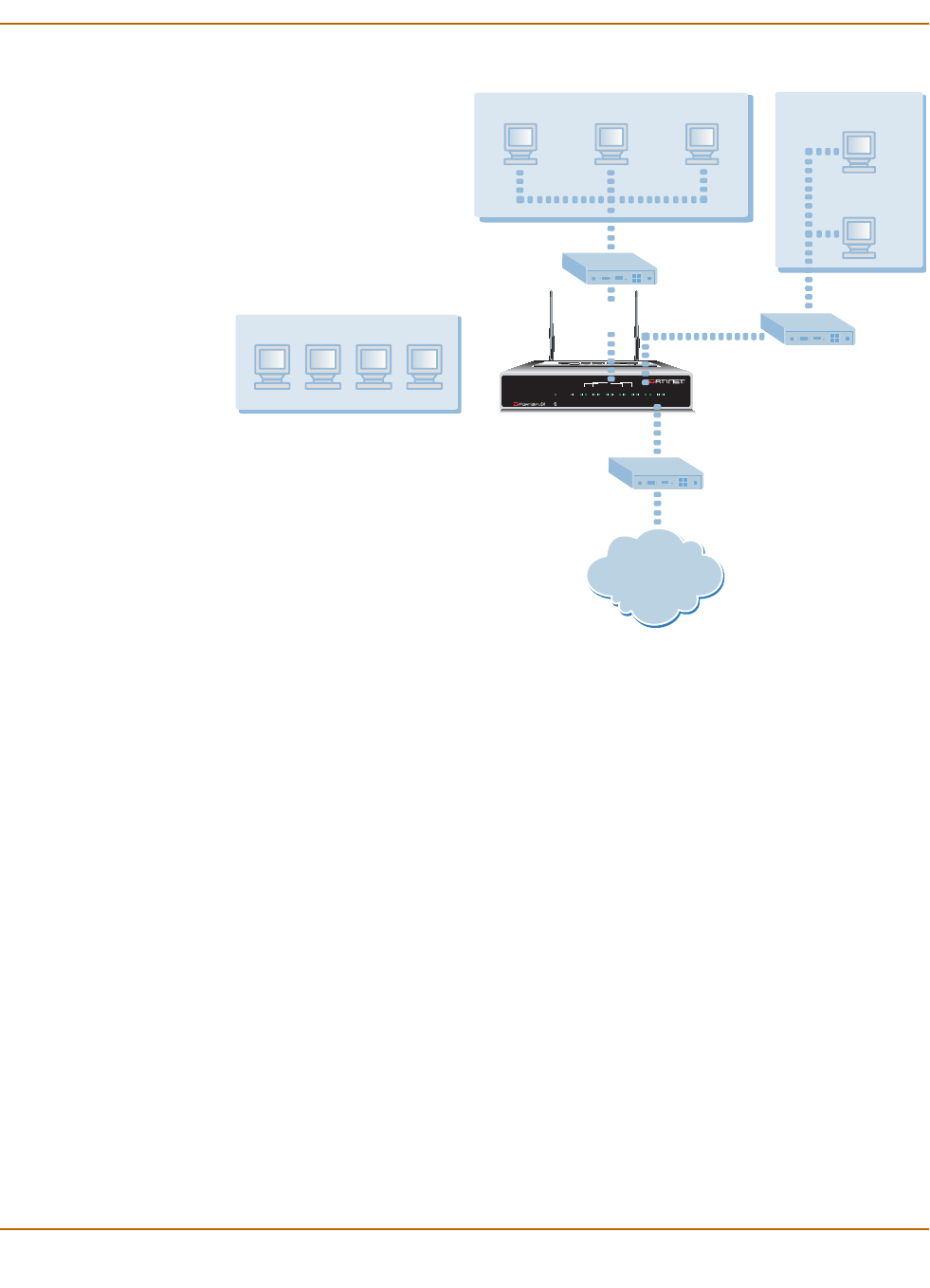
Transparent mode installation Wireless configuration
FortiWiFi-60 Installation and Configuration Guide 63
Figure 8: FortiWiFi-60 Transparent mode connections
In Transparent mode, the FortiWiFi unit does not change the layer 3 topology. This
means that all of its interfaces are on the same IP subnet and that it appears to other
devices as a bridge. Typically, the FortiWiFi unit would be deployed in Transparent
mode when it is intended to provide antivirus and content scanning behind an existing
firewall solution.
A FortiWiFi unit in Transparent mode can also perform firewalling. Even though it
takes no part in the layer 3 topology, it can examine layer 3 header information and
make decisions on whether to block or pass traffic.
Wireless configuration
Use the information in “Wireless configuration” on page 120 to complete the FortiWiFi-
60 wireless configuration.
Completing the configuration
Use the information in this section to complete the initial configuration of the FortiWiFi
unit.
INTERNAL
DMZ4321
LINK 100 LINK 100 LINK 100 LINK 100 LINK 100 LINK 100 LINK 100
WAN1 WAN 2
PWR WLAN
Internet
WAN1
DMZ
FortiWiFi-60
Internal Network Other Network
Hub or Switch
Hub or Switch
Public Switch
or Router
Internal
Wireless Network

64 Fortinet Inc.
Completing the configuration Transparent mode installation
Setting the date and time
For effective scheduling and logging, the FortiWiFi system date and time should be
accurate. You can either manually set the date and time or you can configure the
FortiWiFi unit to automatically keep its date and time correct by synchronizing with a
Network Time Protocol (NTP) server.
To set the FortiWiFi system date and time, see “Setting system date and time” on
page 143.
Enabling antivirus protection
To enable antivirus protection to protect users on your internal network from
downloading a virus from the Internet:
1Go to Firewall > Policy > Internal->WAN1.
2Select Edit to edit this policy.
3Select Anti-Virus & Web filter to enable antivirus protection for this policy.
4Select the Scan Content Profile.
5Select OK to save your changes.
Registering your FortiWiFi
After purchasing and installing a new FortiWiFi unit, you can register the unit by going
to System > Update > Support, or using a web browser to connect to
http://support.fortinet.com and selecting Product Registration.
Registration consists of entering your contact information and the serial numbers of
the FortiWiFi units you or your organization have purchased. Registration is quick and
easy. You can register multiple FortiWiFi units in a single session without re-entering
your contact information.
For more information about registration, see “Registering FortiGate and FortiWiFi
units” on page 104.
Configuring virus and attack definition updates
You can configure the FortiWiFi unit to automatically check to see if new versions of
the virus definitions and attack definitions are available. If it finds new versions, the
FortiWiFi unit automatically downloads and installs the updated definitions.
The FortiWiFi unit uses HTTPS on port 8890 to check for updates. The FortiWiFi
WAN1 interface must have a path to the FortiResponse Distribution Network (FDN)
using port 8890.
To configure automatic virus and attack updates, see “Updating antivirus and attack
definitions” on page 93.

Transparent mode installation Transparent mode configuration examples
FortiWiFi-60 Installation and Configuration Guide 65
Transparent mode configuration examples
A FortiWiFi unit operating in Transparent mode still requires a basic configuration to
operate as a node on the IP network. As a minimum, the FortiWiFi unit must be
configured with an IP address and subnet mask. These are used for management
access and to allow the unit to receive antivirus and definitions updates. Also, the unit
must have sufficient route information to reach:
• the management computer,
• The FortiResponse Distribution Network (FDN),
• a DNS server.
A route is required whenever the FortiWiFi unit connects to a router to reach a
destination. If all of the destinations are located on the external network, you may be
required to enter only a single default route. If, however, the network topology is more
complex, you may be required to enter one or more static routes in addition to the
default route.
This section describes:
•Default routes and static routes
•Example default route to an external network
•Example static route to an external destination
•Example static route to an internal destination
Default routes and static routes
To create a route to a destination, you need to define an IP prefix which consists of an
IP network address and a corresponding netmask value. A default route matches any
prefix and forwards traffic to the next hop router (otherwise known as the default
gateway). A static route matches a more specific prefix and forwards traffic to the next
hop router.
Default route example:
Static Route example:
IP Prefix 0.0.0.0 (IP address)
0.0.0.0 (Netmask)
Next Hop 192.168.1.2
IP Prefix 172.100.100.0 (IP address)
255.255.255.0 (Netmask)
Next Hop 192.168.1.2
Note: When adding routes to the FortiWiFi unit, add the default route last so that it
appears on the bottom of the route list. This ensures that the unit will attempt to match
more specific routes before selecting the default route.
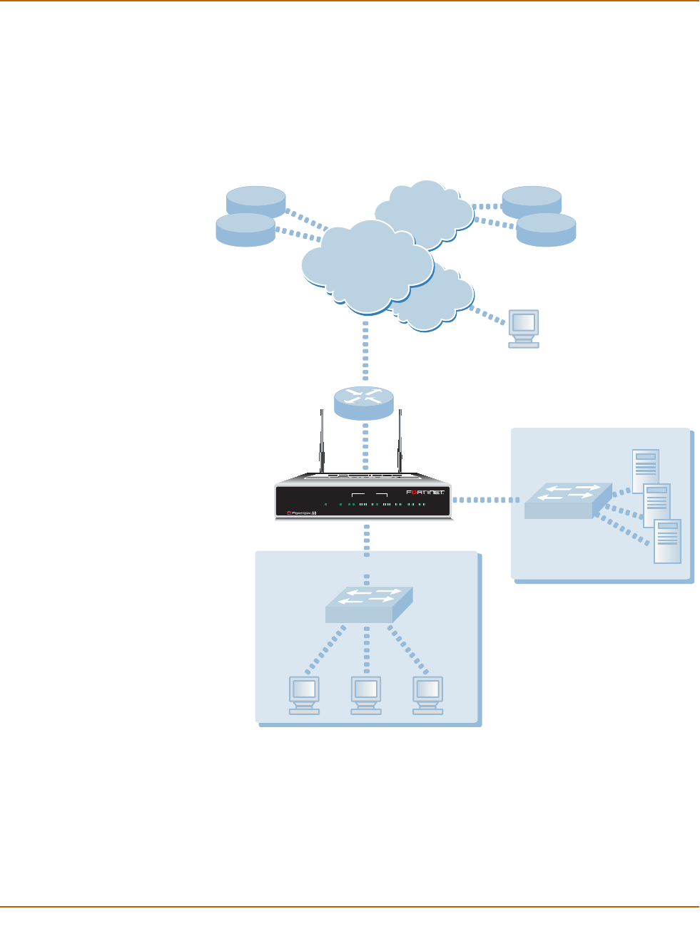
66 Fortinet Inc.
Transparent mode configuration examples Transparent mode installation
Example default route to an external network
Figure 9 shows a FortiWiFi unit where all destinations, including the management
computer, are located on the external network. To reach these destinations, the
FortiWiFi unit must connect to the “upstream” router leading to the external network.
To facilitate this connection, you must enter a single default route that points to the
upstream router as the next hop/default gateway.
Figure 9: Default route to an external network
General configuration steps
1Set the FortiWiFi unit to operate in Transparent mode.
2Configure the Management IP address and Netmask of the FortiWiFi unit.
3Configure the default route to the external network.
Internal Network
DMZ
Internet
Upstream
Router
Gateway IP 192.168.1.2
Management IP
192.168.1.1
DNS FortiResponse
Distribution
Network (FDN)
Management
Computer
FortiWiFi-60
INTERNAL
DMZ4321
LINK 100 LINK 100 LINK 100 LINK 100 LINK 100 LINK 100 LINK 100
WAN1 WAN 2
PWR WLAN

Transparent mode installation Transparent mode configuration examples
FortiWiFi-60 Installation and Configuration Guide 67
Web-based manager example configuration steps
To configure basic Transparent mode settings and a default route using the
web-based manager:
1Go to System > Status.
• Select Change to Transparent Mode.
• Select Transparent in the Operation Mode list.
•Select OK.
The FortiWiFi unit changes to Transparent mode.
2Go to System > Network > Management.
• Change the Management IP and Netmask:
IP: 192.168.1.1
Mask: 255.255.255.0
• Select Apply.
3Go to System > Network > Routing.
• Select New to add the default route to the external network.
Destination IP: 0.0.0.0
Mask: 0.0.0.0
Gateway: 192.168.1.2
•Select OK.
CLI configuration steps
To configure the Fortinet basic settings and a default route using the CLI:
1Change the system to operate in Transparent Mode.
set system opmode transparent
2Add the Management IP address and Netmask.
set system management ip 192.168.1.1 255.255.255.0
3Add the default route to the external network.
set system route number 1 gw1 192.168.1.2
Example static route to an external destination
Figure 10 shows a FortiWiFi unit that requires routes to the FDN located on the
external network. The FortiWiFi unit does not require routes to the DNS servers or
management computer because they are located on the internal network.
To connect to the FDN, you would typically enter a single default route to the external
network. However, to provide an extra degree of security, you could enter static routes
to a specific FortiResponse server in addition to a default route to the external
network. If the static route becomes unavailable (perhaps because the IP address of
the FortiResponse server changes) the FortiWiFi unit will still be able to receive
antivirus and NIDS updates from the FDN using the default route.
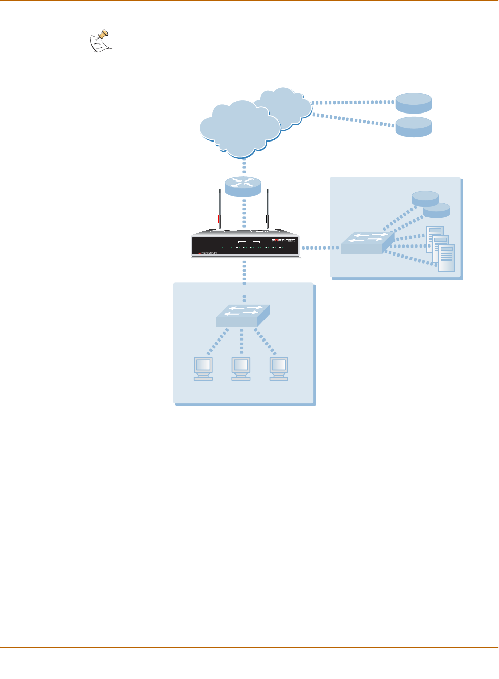
68 Fortinet Inc.
Transparent mode configuration examples Transparent mode installation
Figure 10: Static route to an external destination
General configuration steps
1Set the FortiWiFi unit to operate in Transparent mode.
2Configure the Management IP address and Netmask of the FortiWiFi unit.
3Configure the static route to the FortiResponse server.
4Configure the default route to the external network.
Note: This is an example configuration only. To configure a static route, you require a
destination IP address.
Management
Computer
Internal Network
DMZ
Internet
Upstream
Router
Gateway IP 192.168.1.2
Management IP
192.168.1.1
FortiResponse
Distribution
Network (FDN)
DNS
24.102.233.5
FortiWiFi-60
INTERNAL
DMZ4321
LINK 100 LINK 100 LINK 100 LINK 100 LINK 100 LINK 100 LINK 100
WAN1 WAN 2
PWR WLAN

Transparent mode installation Transparent mode configuration examples
FortiWiFi-60 Installation and Configuration Guide 69
Web-based manager example configuration steps
To configure the basic FortiWiFi settings and a static route using the web-based
manager:
1Go to System > Status.
• Select Change to Transparent Mode.
• Select Transparent in the Operation Mode list.
•Select OK.
The FortiWiFi unit changes to Transparent mode.
2Go to System > Network > Management.
• Change the Management IP and Netmask:
IP: 192.168.1.1
Mask: 255.255.255.0
• Select Apply.
3Go to System > Network > Routing.
• Select New to add the static route to the FortiResponse server.
Destination IP: 24.102.233.5
Mask: 255.255.255.0
Gateway: 192.168.1.2
•Select OK.
• Select New to add the default route to the external network.
Destination IP: 0.0.0.0
Mask: 0.0.0.0
Gateway: 192.168.1.2
•Select OK.
CLI configuration steps
To configure the Fortinet basic settings and a static route using the CLI:
1Set the system to operate in Transparent Mode.
set system opmode transparent
2Add the Management IP address and Netmask.
set system management ip 192.168.1.1 255.255.255.0
3Add the static route to the primary FortiResponse server.
set system route number 1 dst 24.102.233.5 255.255.255.0 gw1
192.168.1.2
4Add the default route to the external network.
set system route number 2 gw1 192.168.1.2
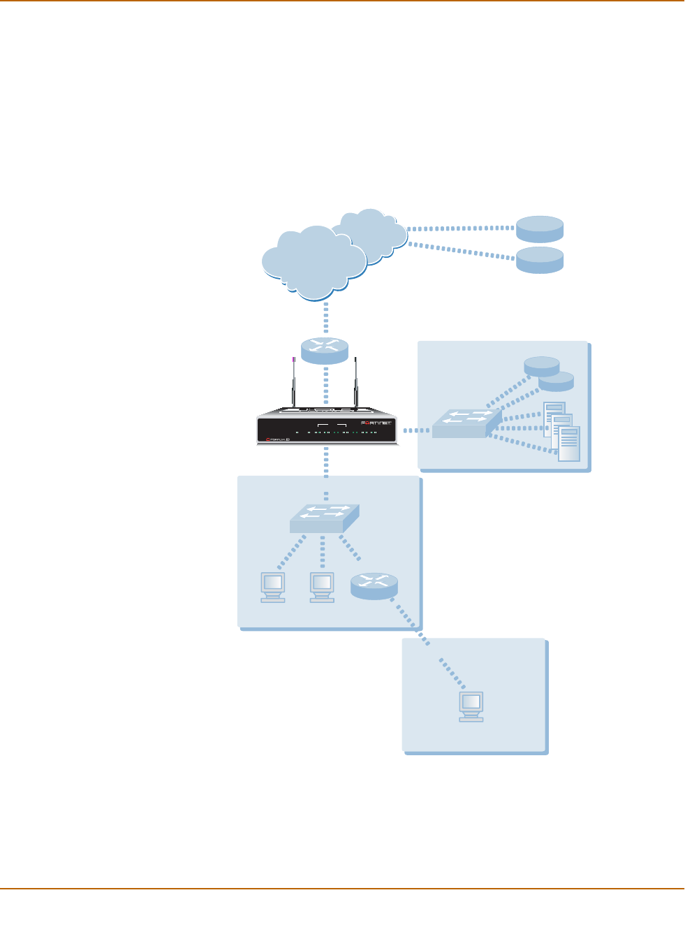
70 Fortinet Inc.
Transparent mode configuration examples Transparent mode installation
Example static route to an internal destination
Figure 11 shows a FortiWiFi unit where the FDN is located on an external subnet and
the management computer is located on a remote, internal subnet. To reach the FDN,
you need to enter a single default route that points to the upstream router as the next
hop/default gateway. To reach the management computer, you need to enter a single
static route that leads directly to it. This route will point to the internal router as the
next hop. (No route is required for the DNS servers because they are on the same
layer 3 subnet as the FortiWiFi unit.)
Figure 11: Static route to an internal destination
General configuration steps
1Set the unit to operate in Transparent mode.
2Configure the Management IP address and Netmask of the FortiWiFi unit.
3Configure the static route to the management computer on the internal network.
Management Computer
172.16.1.11
Internal Network A
Internal Network B
DMZ
Internet
Upstream
Router
Internal
Router
Gateway IP 192.168.1.2
Management IP
192.168.1.1
FortiResponse
Distribution
Network (FDN)
Gateway IP
192.168.1.3
DNS
FortiWiFi-60
INTERNAL
DMZ4321
LINK 100 LINK 100 LINK 100 LINK 100 LINK 100 LINK 100 LINK 100
WAN1 WAN2
PWR WLAN

Transparent mode installation Transparent mode configuration examples
FortiWiFi-60 Installation and Configuration Guide 71
4Configure the default route to the external network.
Web-based manager example configuration steps
To configure the FortiWiFi basic settings, a static route, and a default route using the
web-based manager:
1Go to System > Status.
• Select Change to Transparent Mode.
• Select Transparent in the Operation Mode list.
•Select OK.
The FortiWiFi unit changes to Transparent mode.
2Go to System > Network > Management.
• Change the Management IP and Netmask:
IP: 192.168.1.1
Mask: 255.255.255.0
• Select Apply.
3Go to System > Network > Routing.
• Select New to add the static route to the management computer.
Destination IP: 172.16.1.11
Mask: 255.255.255.0
Gateway: 192.168.1.3
•Select OK.
• Select New to add the default route to the external network.
Destination IP: 0.0.0.0
Mask: 0.0.0.0
Gateway: 192.168.1.2
•Select OK.
CLI configuration steps
To configure the FortiWiFi basic settings, a static route, and a default route using the
CLI:
1Set the system to operate in Transparent Mode.
set system opmode transparent
2Add the Management IP address and Netmask.
set system management ip 192.168.1.1 255.255.255.0
3Add the static route to the management computer.
set system route number 1 dst 172.16.1.11 255.255.255.0 gw1
192.168.1.3
4Add the default route to the external network.
set system route number 2 gw1 192.168.1.2

72 Fortinet Inc.
Transparent mode configuration examples Transparent mode installation

FortiWiFi-60 Installation and Configuration Guide Version 2.50
FortiWiFi-60 Installation and Configuration Guide 73
System status
You can connect to the web-based manager and view the current system status of the
FortiWiFi unit. The status information that is displayed includes the current firmware
version, the current virus and attack definitions, and the FortiWiFi unit serial number.
If you log into the web-based manager using the admin administrator account, you
can make any of the following changes to the FortiWiFi system settings:
•Changing the FortiWiFi host name
•Changing the FortiWiFi firmware
•Manual virus definition updates
•Manual attack definition updates
•Backing up system settings
•Restoring system settings
•Restoring system settings to factory defaults
•Changing to Transparent mode
•Changing to NAT/Route mode
•Restarting the FortiWiFi unit
•Shutting down the FortiWiFi unit
If you log into the web-based manager with another administrator account, you can
view the system settings including:
•Displaying the FortiWiFi serial number
•Displaying the FortiWiFi up time
All administrative users can also go to the Monitor page and view FortiWiFi system
status. System status displays FortiWiFi system health monitoring information,
including CPU and memory status, session and network status.
•System status
All administrative users can also go to the Session page and view the active
communication sessions to and through the FortiWiFi unit.
•Session list

74 Fortinet Inc.
Changing the FortiWiFi host name System status
Changing the FortiWiFi host name
The FortiWiFi host name appears on the Status page and in the FortiWiFi CLI prompt.
The host name is also used as the SNMP system name. For information about the
SNMP system name, see “Configuring SNMP” on page 147.
The default host name is FortiWiFi-60.
To change the FortiWiFi host name
1Go to System > Status.
2Select Edit Host Name .
3Type a new host name.
4Select OK.
The new host name is displayed on the Status page, and in the CLI prompt, and is
added to the SNMP System Name.
Changing the FortiWiFi firmware
After you download a FortiWiFi firmware image from Fortinet, you can use the
procedures listed in Table 1 to install the firmware image on your FortiWiFi unit.
Upgrading to a new firmware version
Use the following procedures to upgrade the FortiWiFi unit to a newer firmware
version.
Table 1: Firmware upgrade procedures
Procedure Description
Upgrading to a new
firmware version Commonly-used web-based manager and CLI procedures to
upgrade to a new FortiOS firmware version or to a more recent
build of the same firmware version.
Reverting to a
previous firmware
version
Use the web-based manager or CLI procedure to revert to a
previous firmware version. This procedure reverts the FortiWiFi unit
to its factory default configuration.
Installing firmware
images from a system
reboot using the CLI
Use this procedure to install a new firmware version or revert to a
previous firmware version. You must run this procedure by
connecting to the CLI using the FortiWiFi console port and a
null-modem cable. This procedure reverts the FortiWiFi unit to its
factory default configuration.
Testing a new
firmware image before
installing it
Use this procedure to test a new firmware image before installing it.
You must run this procedure by connecting to the CLI using the
FortiWiFi console port and a null-modem cable. This procedure
temporarily installs a new firmware image using your current
configuration. You can test the firmware image before installing it
permanently. If the firmware image works correctly you can use
one of the other procedures listed in this table to install it
permanently.

System status Changing the FortiWiFi firmware
FortiWiFi-60 Installation and Configuration Guide 75
Upgrading the firmware using the web-based manager
To upgrade the firmware using the web-based manager
1Copy the firmware image file to your management computer.
2Log into the web-based manager as the admin administrative user.
3Go to System > Status.
4Select Firmware Upgrade .
5Type the path and filename of the firmware image file, or select Browse and locate the
file.
6Select OK.
The FortiWiFi unit uploads the firmware image file, upgrades to the new firmware
version, restarts, and displays the FortiWiFi login. This process takes a few minutes.
7Log into the web-based manager.
8Go to System > Status and check the Firmware Version to confirm that the firmware
upgrade is successfully installed.
9Update antivirus and attack definitions. For information about antivirus and attack
definitions, see “Manually initiating antivirus and attack definitions updates” on
page 95.
Upgrading the firmware using the CLI
To use the following procedure you must have a TFTP server that the FortiWiFi unit
can connect to.
To upgrade the firmware using the CLI
1Make sure that the TFTP server is running.
2Copy the new firmware image file to the root directory of the TFTP server.
3Log into the CLI as the admin administrative user.
4Make sure the FortiWiFi unit can connect to the TFTP server.
You can use the following command to ping the computer running the TFTP server.
For example, if the IP address of the TFTP server is 192.168.1.168:
execute ping 192.168.1.168
Note: Installing firmware replaces the current antivirus and attack definitions with the definitions
included with the firmware release that you are installing. After you install new firmware, use the
procedure “Manually initiating antivirus and attack definitions updates” on page 95 to make sure
that antivirus and attack definitions are up to date.
Note: Installing firmware replaces your current antivirus and attack definitions with the
definitions included with the firmware release that you are installing. After you install new
firmware, use the procedure “Manually initiating antivirus and attack definitions updates” on
page 95 to make sure that antivirus and attack definitions are up to date. You can also use the
CLI command execute updatecenter updatenow to update the antivirus and attack
definitions.

76 Fortinet Inc.
Changing the FortiWiFi firmware System status
5Enter the following command to copy the firmware image from the TFTP server to the
FortiWiFi unit:
execute restore image <name_str> <tftp_ip>
Where <name_str> is the name of the firmware image file on the TFTP server and
<tftp_ip> is the IP address of the TFTP server. For example, if the firmware image
file name is FGT_300-v250-build045-FORTINET.out and the IP address of the
TFTP server is 192.168.1.168, enter:
execute restore image FGT_300-v250-build045-FORTINET.out
192.168.1.168
The FortiWiFi unit uploads the firmware image file, upgrades to the new firmware
version, and restarts. This process takes a few minutes.
6Reconnect to the CLI.
7To confirm that the new firmware image is successfully installed, enter:
get system status
8Use the procedure “Manually initiating antivirus and attack definitions updates” on
page 95 to update antivirus and attack definitions, or from the CLI, enter:
execute updatecenter updatenow
9To confirm that the antivirus and attack definitions are successfully updated, enter the
following command to display the antivirus engine, virus and attack definitions version,
contract expiry, and last update attempt information.
get system objver
Reverting to a previous firmware version
Use the following procedures to revert your FortiWiFi unit to a previous firmware
version.
Reverting to a previous firmware version using the web-based
manager
The following procedures revert the FortiWiFi unit to its factory default configuration
and delete NIDS user-defined signatures, web content lists, email filtering lists, and
changes to replacement messages.
Before beginning this procedure you can:
• Back up the FortiWiFi unit configuration. For information, see “Backing up system
settings” on page 84.
• Back up the NIDS user-defined signatures. For information, see the FortiGate
NIDS Guide
• Back up web content and email filtering lists. For information, see the FortiGate
Content Protection Guide.
If you are reverting to a previous FortiOS version (for example, reverting from FortiOS
v2.50 to FortiOS v2.36) you might not be able to restore the previous configuration
from the backup configuration file.

System status Changing the FortiWiFi firmware
FortiWiFi-60 Installation and Configuration Guide 77
To revert to a previous firmware version using the web-based manager
1Copy the firmware image file to your management computer.
2Log into the FortiWiFi web-based manager as the admin administrative user.
3Go to System > Status.
4Select Firmware Upgrade .
5Type the path and filename of the previous firmware image file, or select Browse and
locate the file.
6Select OK.
The FortiWiFi unit uploads the firmware image file, reverts to the old firmware version,
resets the configuration, restarts, and displays the FortiWiFi login. This process takes
a few minutes.
7Log into the web-based manager.
8Go to System > Status and check the Firmware Version to confirm that the firmware
is successfully installed.
9Restore your configuration.
For information about restoring your configuration, see “Restoring system settings” on
page 84.
10 Update antivirus and attack definitions. For information about antivirus and attack
definitions, see “Manually initiating antivirus and attack definitions updates” on
page 95.
Reverting to a previous firmware version using the CLI
This procedure reverts your FortiWiFi unit to its factory default configuration and
deletes NIDS user-defined signatures, web content lists, email filtering lists, and
changes to replacement messages.
Before beginning this procedure you can:
• Back up the FortiWiFi unit configuration using the command execute backup
config.
• Back up the NIDS user defined signatures using the command execute backup
nidsuserdefsig
• Back up web content and email filtering lists. For information, see the FortiGate
Content Protection Guide.
If you are reverting to a previous FortiOS version (for example, reverting from FortiOS
v2.50 to FortiOS v2.36) you might not be able to restore your previous configuration
from the backup configuration file.
Note: Installing firmware replaces the current antivirus and attack definitions with the definitions
included with the firmware release that you are installing. After you install new firmware, use the
procedure “Manually initiating antivirus and attack definitions updates” on page 95 to make sure
that antivirus and attack definitions are up to date.

78 Fortinet Inc.
Changing the FortiWiFi firmware System status
To use the following procedure you must have a TFTP server that the FortiWiFi unit
can connect to.
To revert to a previous firmware version using the CLI
1Make sure that the TFTP server is running.
2Copy the new firmware image file to the root directory of the TFTP server.
3Log into the FortiWiFi CLI as the admin administrative user.
4Make sure the FortiWiFi unit can connect to the TFTP server.
You can use the following command to ping the computer running the TFTP server.
For example, if the TFTP server's IP address is 192.168.1.168:
execute ping 192.168.1.168
5Enter the following command to copy the firmware image from the TFTP server to the
FortiWiFi unit:
execute restore image <name_str> <tftp_ip>
Where <name_str> is the name of the firmware image file on the TFTP server and
<tftp_ip> is the IP address of the TFTP server. For example, if the firmware image
file name is FGT_300-v250-build045-FORTINET.out and the IP address of the
TFTP server is 192.168.1.168, enter:
execute restore image FGT_300-v250-build045-FORTINET.out
192.168.1.168
The FortiWiFi unit uploads the firmware image file. After the file uploads, a message
similar to the following is displayed:
Get image from tftp server OK.
This operation will downgrade the current firmware version!
Do you want to continue? (y/n)
6Type Y.
7The FortiWiFi unit reverts to the old firmware version, resets the configuration to
factory defaults, and restarts. This process takes a few minutes.
8Reconnect to the CLI.
9To confirm that the new firmware image has been loaded, enter:
get system status
10 Restore your previous configuration. Use the following command:
execute restore config
11 Update antivirus and attack definitions. For information, see “Manually initiating
antivirus and attack definitions updates” on page 95, or from the CLI, enter:
execute updatecenter updatenow
Note: Installing firmware replaces the current antivirus and attack definitions with the definitions
included with the firmware release that you are installing. After you install new firmware, use the
procedure “Manually initiating antivirus and attack definitions updates” on page 95 to make sure
that antivirus and attack definitions are up to date. You can also use the CLI command
execute updatecenter updatenow to update the antivirus and attack definitions.

System status Changing the FortiWiFi firmware
FortiWiFi-60 Installation and Configuration Guide 79
12 To confirm that the antivirus and attack definitions have been updated, enter the
following command to display the antivirus engine, virus and attack definitions version,
contract expiry, and last update attempt information.
get system objver
Installing firmware images from a system reboot using the CLI
This procedure installs a specified firmware image and resets the FortiWiFi unit to
default settings. You can use this procedure to upgrade to a new firmware version,
revert to an older firmware version, or re-install the current firmware version.
To perform this procedure you:
• access the CLI by connecting to the FortiWiFi console port using a null-modem
cable,
• install a TFTP server that you can connect to from the FortiWiFi internal interface.
The TFTP server should be on the same subnet as the internal interface.
Before beginning this procedure you can:
• Back up the FortiWiFi unit configuration. For information, see “Backing up system
settings” on page 84.
• Back up the NIDS user defined signatures. For information, see the FortiGate
NIDS Guide.
• Back up web content and email filtering lists. For information, see the FortiGate
Content Protection Guide.
If you are reverting to a previous FortiOS version (for example, reverting from FortiOS
v2.50 to FortiOS v2.36) you might not be able to restore your previous configuration
from the backup configuration file.
To install firmware from a system reboot
1Connect to the CLI using the null-modem cable and FortiWiFi console port.
2Make sure that the TFTP server is running.
3Copy the new firmware image file to the root directory of the TFTP server.
4Make sure that the internal interface is connected to the same network as the TFTP
server.
5To confirm that the FortiWiFi unit can connect to the TFTP server, use the following
command to ping the computer running the TFTP server. For example, if the IP
address of the TFTP server is 192.168.1.168, enter:
execute ping 192.168.1.168
Note: Installing firmware replaces the current antivirus and attack definitions with the definitions
included with the firmware release that you are installing. After you install new firmware, use the
procedure “Manually initiating antivirus and attack definitions updates” on page 95 to make sure
that antivirus and attack definitions are up to date.

80 Fortinet Inc.
Changing the FortiWiFi firmware System status
6Enter the following command to restart the FortiWiFi unit:
execute reboot
As the FortiWiFi unit starts, a series of system startup messages is displayed.
When the following message appears:
Press any key to enter configuration menu.....
......
7Immediately press any key to interrupt the system startup.
If you successfully interrupt the startup process, the following message appears:
[G]: Get firmware image from TFTP server.
[F]: Format boot device.
[B]: Boot with backup firmware and set as default.
[Q]: Quit menu and continue to boot with default firmware.
[H]: Display this list of options.
Enter G,F,B,Q,or H:
8Type G to get the new firmware image from the TFTP server.
9Type the address of the TFTP server and press Enter.
The following message appears:
Enter Local Address [192.168.1.188]:
10 Type the address of the internal interface of the FortiWiFi unit and press Enter.
The following message appears:
Enter File Name [image.out]:
11 Enter the firmware image filename and press Enter.
The TFTP server uploads the firmware image file to the FortiWiFi unit and messages
similar to the following are displayed:
Save as Default firmware/Run image without saving:[D/R]
Save as Default firmware/Backup firmware/Run image without
saving:[D/B/R]
12 Type D.
The FortiWiFi unit installs the new firmware image and restarts. The installation might
take a few minutes to complete.
Restoring the previous configuration
Change the internal interface addresses if required. You can do this from the CLI
using the command:
set system interface
Note: You have only 3 seconds to press any key. If you do not press a key soon enough, the
FortiWiFi unit reboots and you must log in and repeat the execute reboot command.
Note: The local IP address is used only to download the firmware image. After the firmware is
installed, the address of this interface is changed back to the default IP address for this
interface.

System status Changing the FortiWiFi firmware
FortiWiFi-60 Installation and Configuration Guide 81
After changing the interface addresses, you can access the FortiWiFi unit from the
web-based manager and restore the configuration.
• To restore the FortiWiFi unit configuration, see “Restoring system settings” on
page 84.
• To restore NIDS user defined signatures, see “Adding user-defined signatures” on
page 240.
• To restore web content filtering lists, see “Restoring the Banned Word list” on
page 256 and “Uploading a URL block list” on page 258
• To restore email filtering lists, see “Uploading the email banned word list” on
page 269 and “Uploading an email block list” on page 271.
If you are reverting to a previous firmware version (for example, reverting from
FortiOS v2.50 to FortiOS v2.36) you might not be able to restore your previous
configuration from the backup up configuration file.
Update the virus and attack definitions to the most recent version, see “Manually
initiating antivirus and attack definitions updates” on page 95.
Testing a new firmware image before installing it
You can test a new firmware image by installing the firmware image from a system
reboot and saving it to system memory. After completing this procedure the FortiWiFi
unit operates using the new firmware image with the current configuration. This new
firmware image is not permanently installed. The next time the FortiWiFi unit restarts,
it operates with the originally installed firmware image using the current configuration.
If the new firmware image operates successfully, you can install it permanently using
the procedure “Upgrading to a new firmware version” on page 74.
To run this procedure you:
• access the CLI by connecting to the FortiWiFi console port using a null-modem
cable,
• install a TFTP server that you can connect to from the FortiWiFi internal interface.
The TFTP server should be on the same subnet as the internal interface.
To test a new firmware image
1Connect to the CLI using a null-modem cable and FortiWiFi console port.
2Make sure the TFTP server is running.
3Copy the new firmware image file to the root directory of the TFTP server.
You can use the following command to ping the computer running the TFTP server.
For example, if the TFTP server's IP address is 192.168.1.168:
execute ping 192.168.1.168
4Enter the following command to restart the FortiWiFi unit:
execute reboot
5As the FortiWiFi unit reboots, press any key to interrupt the system startup.
As the FortiWiFi units starts, a series of system startup messages are displayed.
When the following message appears:
Press any key to enter configuration menu.....
......

82 Fortinet Inc.
Manual virus definition updates System status
6Immediately press any key to interrupt the system startup.
If you successfully interrupt the startup process, the following message appears:
[G]: Get firmware image from TFTP server.
[F]: Format boot device.
[Q]: Quit menu and continue to boot with default firmware.
[H]: Display this list of options.
Enter G,F,Q,or H:
7Type G to get the new firmware image from the TFTP server.
8Type the address of the TFTP server and press Enter.
The following message appears:
Enter Local Address [192.168.1.188]:
9Type the address of the internal interface of the FortiWiFi unit and press Enter.
The following message appears:
Enter File Name [image.out]:
10 Enter the firmware image file name and press Enter.
The TFTP server uploads the firmware image file to the FortiWiFi unit and messages
similar to the following appear.
Save as Default firmware/Run image without saving:[D/R]
11 Type R.
The FortiWiFi image is installed to system memory and the FortiWiFi unit starts
running the new firmware image but with its current configuration.
12 You can log into the CLI or the web-based manager using any administrative account.
13 To confirm that the new firmware image has been loaded, from the CLI enter:
get system status
You can test the new firmware image as required.
Manual virus definition updates
The Status page of the FortiWiFi web-based manager displays the current installed
versions of the FortiWiFi antivirus definitions.
Note: You have only 3 seconds to press any key. If you do not press a key soon enough, the
FortiWiFi unit reboots and you must log in and repeat the execute reboot command.
Note: The local IP address is used only to download the firmware image. After the firmware is
installed, the address of this interface is changed back to the default IP address for this
interface.

System status Manual attack definition updates
FortiWiFi-60 Installation and Configuration Guide 83
To update the antivirus definitions manually
1Download the latest antivirus definitions update file from Fortinet and copy it to the
computer that you use to connect to the web-based manager.
2Start the web-based manager and go to System > Status.
3In the Antivirus Definitions Version section, select Definitions Update .
4Type the path and filename for the antivirus definitions update file, or select Browse
and locate the antivirus definitions update file.
5Select OK to copy the antivirus definitions update file to the FortiWiFi unit.
The FortiWiFi unit updates the antivirus definitions. This takes about 1 minute.
6Go to System > Status to confirm that the Antivirus Definitions Version information
has updated.
Manual attack definition updates
The Status page of the FortiWiFi web-based manager displays the current installed
versions of the FortiWiFi Attack Definitions used by the Network Intrusion Detection
System (NIDS).
To update the attack definitions manually
1Download the latest attack definitions update file from Fortinet and copy it to the
computer that you use to connect to the web-based manager.
2Start the web-based manager and go to System > Status.
3In the Attack Definitions Version section, select Definitions Update .
4Type the path and filename for the attack definitions update file, or select Browse and
locate the attack definitions update file.
5Select OK to copy the attack definitions update file to the FortiWiFi unit.
The FortiWiFi unit updates the attack definitions. This takes about 1 minute.
6Go to System > Status to confirm that the Attack Definitions Version information has
updated.
Note: For information about configuring the FortiWiFi unit for automatic antivirus definitions
updates, see “Virus and attack definitions updates and registration” on page 93. You can also
manually start an antivirus definitions update by going to System > Update and selecting
Update Now.
Note: For information about configuring the FortiWiFi unit for automatic attack definitions
updates, see “Virus and attack definitions updates and registration” on page 93. You can also
manually start an attack definitions update by going to System > Update and selecting Update
Now.

84 Fortinet Inc.
Displaying the FortiWiFi serial number System status
Displaying the FortiWiFi serial number
1Go to System > Status.
The serial number is displayed on the System Status page of the web-based
manager. The serial number is specific to the FortiWiFi unit and does not change with
firmware upgrades.
Displaying the FortiWiFi up time
1Go to System > Status.
The FortiWiFi up time displays the time in days, hours, and minutes since the
FortiWiFi unit was last started.
Backing up system settings
You can back up system settings by downloading them to a text file on the
management computer.
To back up system settings
1Go to System > Status.
2Select System Settings Backup.
3Select Backup System Settings.
4Type a name and location for the file.
The system settings file is backed up to the management computer.
5Select Return to go back to the Status page.
Restoring system settings
You can restore system settings by uploading a previously downloaded system
settings text file.
To restore system settings
1Go to System > Status.
2Select System Settings Restore.
3Enter the path and filename of the system settings file, or select Browse and locate
the file.
4Select OK to restore the system settings file to the FortiWiFi unit.
The FortiWiFi unit restarts, loading the new system settings.
5Reconnect to the web-based manager and review your configuration to confirm that
the uploaded system settings have taken effect.

System status Restoring system settings to factory defaults
FortiWiFi-60 Installation and Configuration Guide 85
Restoring system settings to factory defaults
Use the following procedure to restore system settings to the values set at the factory.
This procedure does not change the firmware version or the antivirus or attack
definitions.
To restore system settings to factory defaults
1Go to System > Status.
2Select Restore Factory Defaults.
3Select OK to confirm.
The FortiWiFi unit restarts with the configuration that it had when it was first powered
on.
4Reconnect to the web-based manager and review the system configuration to confirm
that it has been reset to the default settings.
For information about restoring system settings, see “Restoring system settings” on
page 84.
Changing to Transparent mode
Use the following procedure to change the FortiWiFi unit from NAT/Route mode to
Transparent mode. After you change the FortiWiFi unit to Transparent mode, most of
the configuration resets to Transparent mode factory defaults.
The following items are not set to Transparent mode factory defaults:
• The admin administrator account password (see “Adding and editing administrator
accounts” on page 145)
• Custom replacement messages (see “Replacement messages” on page 155)
To change to Transparent mode
1Go to System > Status.
2Select Change to Transparent Mode.
3Select Transparent in the operation mode list.
4Select OK.
The FortiWiFi unit changes operation mode.
5To reconnect to the web-based manager, connect to the interface configured for
Transparent mode management access and browse to https:// followed by the
Transparent mode management IP address.
By default in Transparent mode, you can connect to the internal or DMZ interface. The
default Transparent mode management IP address is 10.10.10.1.
!Caution: This procedure deletes all changes that you have made to the FortiWiFi configuration
and reverts the system to its original configuration, including resetting interface addresses.

86 Fortinet Inc.
Changing to NAT/Route mode System status
Changing to NAT/Route mode
Use the following procedure to change the FortiWiFi unit from Transparent mode to
NAT/Route mode. After you change the FortiWiFi unit to NAT/Route mode, most of the
configuration resets to NAT/Route mode factory defaults.
The following items are not set to NAT/Route mode factory defaults:
• The admin administrator account password (see “Adding and editing administrator
accounts” on page 145)
• Custom replacement messages (see “Replacement messages” on page 155)
To change to NAT/Route mode
1Go to System > Status.
2Select Change to NAT Mode.
3Select NAT/Route in the operation mode list.
4Select OK.
The FortiWiFi unit changes operation mode.
5To reconnect to the web-based manager you must connect to the interface configured
by default for management access.
By default in NAT/Route mode, you can connect to the internal or DMZ interface. The
default Transparent mode management IP address is 192.168.1.99.
Restarting the FortiWiFi unit
1Go to System > Status.
2Select Restart.
The FortiWiFi unit restarts.
Shutting down the FortiWiFi unit
You can restart the FortiWiFi unit after shutdown only by turning the power off and
then on.
1Go to System > Status.
2Select Shutdown.
The FortiWiFi unit shuts down and all traffic flow stops.

System status System status
FortiWiFi-60 Installation and Configuration Guide 87
System status
You can use the system status monitor to display FortiWiFi system health information.
The system health information includes memory usage, the number of active
communication sessions, and the amount of network bandwidth currently in use. The
web-based manager displays current statistics as well as statistics for the previous
minute.
You can also view current virus and intrusion status. The web-based manager
displays the current number of viruses and attacks as well as a graph of virus and
attack levels over the previous 20 hours.
In each case you can set an automatic refresh interval that updates the display every
5 to 30 seconds. You can also refresh the display manually.
•Viewing CPU and memory status
•Viewing sessions and network status
•Viewing virus and intrusions status
Viewing CPU and memory status
Current CPU and memory status indicates how close the FortiWiFi unit is to running at
full capacity. The web-based manager displays CPU and memory usage for core
processes only. CPU and memory use for management processes (for example, for
HTTPS connections to the web-based manager) is excluded.
If CPU and memory use is low, the FortiWiFi unit is able to process much more
network traffic than is currently running. If CPU and memory use is high, the FortiWiFi
unit is performing near its full capacity. Putting additional demands on the system
might cause traffic processing delays.
CPU and memory intensive processes, such as encrypting and decrypting IPSec VPN
traffic, virus scanning, and processing high levels of network traffic containing small
packets, increase CPU and memory usage.
To view CPU and memory status
1Go to System > Status > Monitor.
CPU & Memory status is displayed. The display includes bar graphs of current CPU
and memory usage as well as line graphs of CPU and memory usage for the previous
minute.
2Set the automatic refresh interval and select Go to control how often the web-based
manager updates the display.
More frequent updates use system resources and increase network traffic. However,
this occurs only when you are viewing the display using the web-based manager.
3Select Refresh to manually update the information displayed.
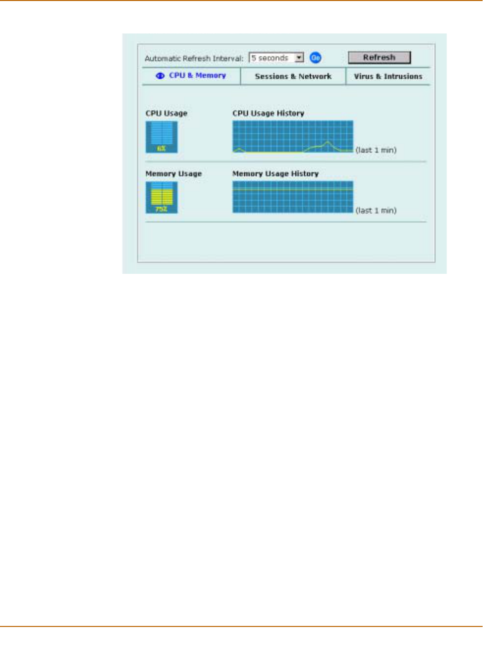
88 Fortinet Inc.
System status System status
Figure 1: CPU and memory status monitor
Viewing sessions and network status
Use the session and network status display to track how many network sessions the
FortiWiFi unit is processing and to see what effect the number of sessions has on the
available network bandwidth. Also, by comparing CPU and memory usage with
session and network status you can see how much demand network traffic is putting
on system resources.
The Sessions section displays the total number of sessions being processed by the
FortiWiFi unit on all interfaces. It also displays the sessions as a percentage of the
maximum number of sessions that the FortiWiFi unit is designed to support.
The Network utilization section displays the total network bandwidth being used
through all FortiWiFi interfaces. It also displays network utilization as a percentage of
the maximum network bandwidth that can be processed by the FortiWiFi unit.
To view sessions and network status
1Go to System > Status > Monitor.
2Select Sessions & Network.
Sessions and network status is displayed. The display includes bar graphs of the
current number of sessions and current network utilization as well as line graphs of
session and network utilization usage for the last minute. The line graph scales are
shown in the upper left corner of the graph.
3Set the automatic refresh interval and select Go to control how often the web-based
manager updates the display.
More frequent updates use system resources and increase network traffic. However,
this only occurs when you are viewing the display using the web-based manager.
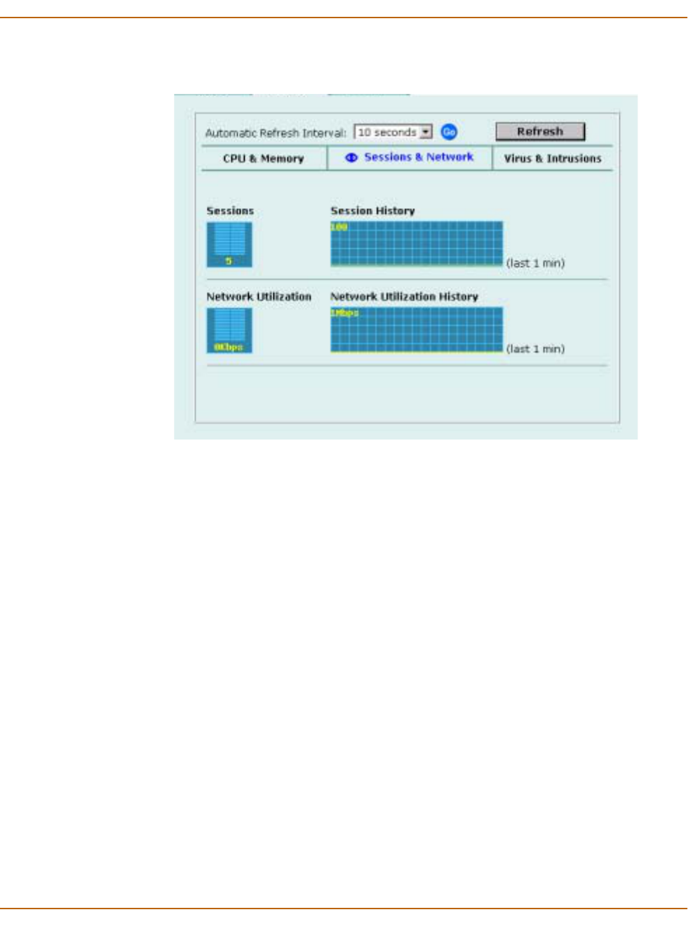
System status System status
FortiWiFi-60 Installation and Configuration Guide 89
4Select Refresh to manually update the information displayed.
Figure 2: Sessions and network status monitor
Viewing virus and intrusions status
Use the virus and intrusions status display to track when viruses are found by the
FortiWiFi antivirus system and to track when the NIDS detects a network-based
attack.
To view virus and intrusions status
1Go to System > Status > Monitor.
2Select Virus & Intrusions.
Virus and intrusions status is displayed. The display includes bar graphs of the
number viruses and intrusions detected per hour as well as line graphs of the number
of viruses and intrusions detected for the last 20 hours.
3Set the automatic refresh interval and select Go to control how often the web-based
manager updates the display.
More frequent updates use system resources and increase network traffic. However,
this only occurs when you are viewing the display using the web-based manager. The
line graph scales are shown on the upper right corner of the graph.
4Select Refresh to manually update the information displayed.
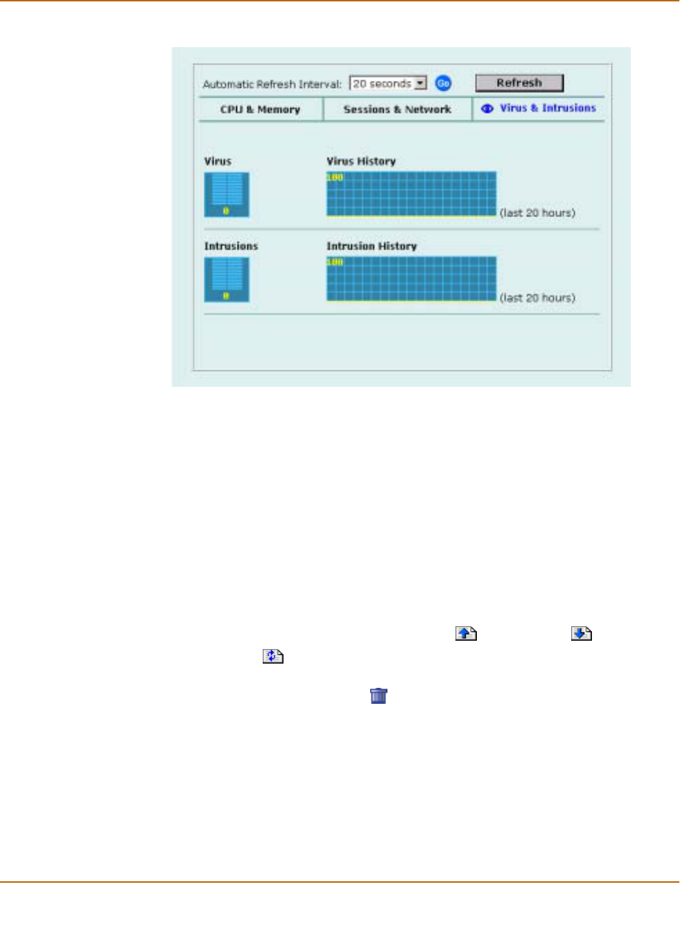
90 Fortinet Inc.
Session list System status
Figure 3: Sessions and network status monitor
Session list
The session list displays information about the communications sessions currently
being processed by the FortiWiFi unit. You can use the session list to view current
sessions. FortiWiFi administrators with read and write permission and the FortiWiFi
admin user can also stop active communication sessions.
To view the session list
1Go to System > Status > Session.
The web-based manager displays the total number of active sessions in the FortiWiFi
unit session table and lists the top 16.
2To navigate the list of sessions, select Page Up or Page Down .
3Select Refresh to update the session list.
4If you are logged in as an administrative user with read and write privileges or as the
admin user, you can select Clear to stop an active session.
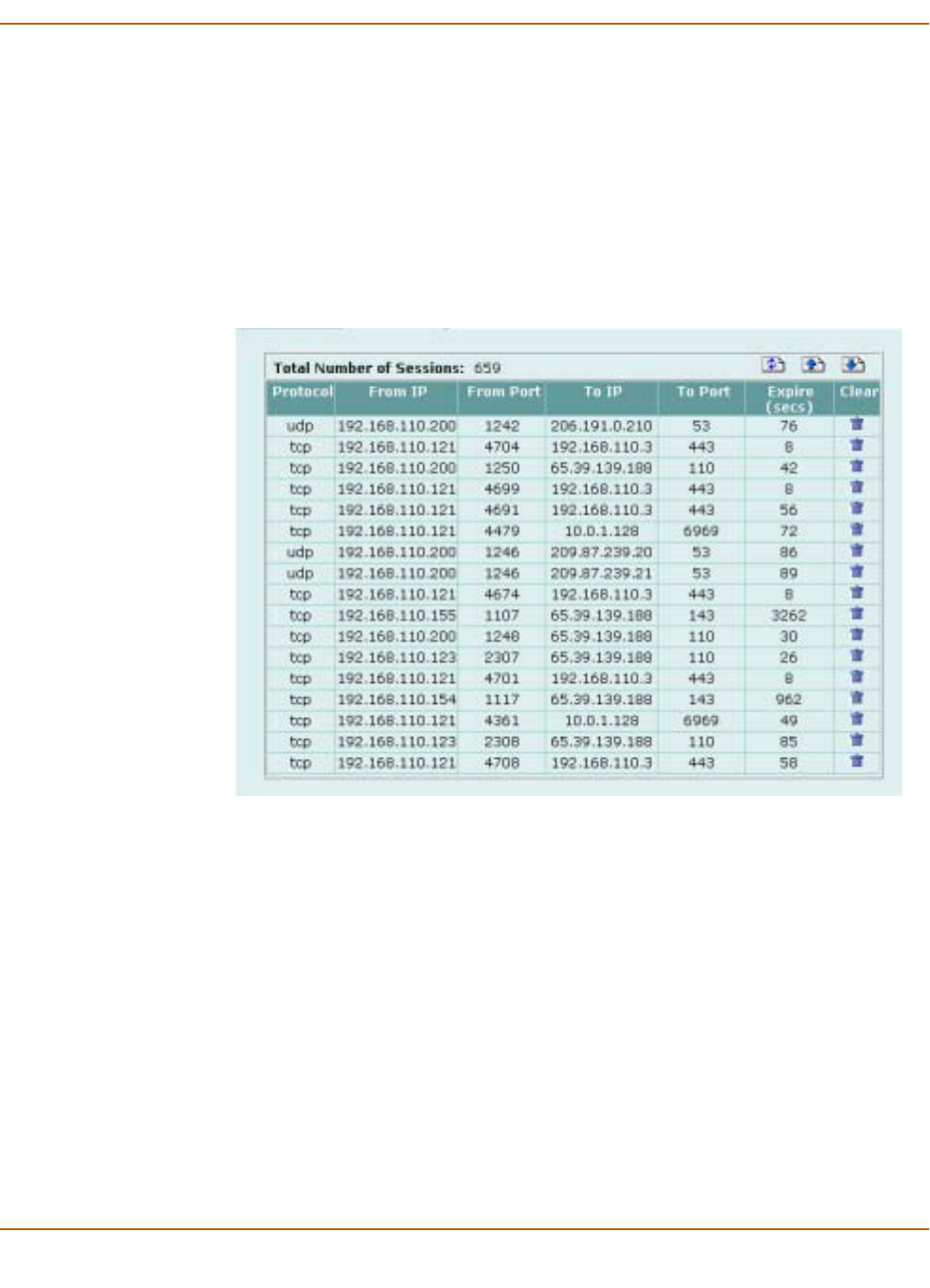
System status Session list
FortiWiFi-60 Installation and Configuration Guide 91
Each line of the session list displays the following information.
Figure 4: Example session list
Protocol The service protocol of the connection, for example, udp, tcp, or icmp.
From IP The source IP address of the connection.
From Port The source port of the connection.
To IP The destination IP address of the connection.
To Port The destination port of the connection.
Expire The time, in seconds, before the connection expires.
Clear Stop an active communication session.

92 Fortinet Inc.
Session list System status

FortiWiFi-60 Installation and Configuration Guide Version 2.50
FortiWiFi-60 Installation and Configuration Guide 93
Virus and attack definitions updates
and registration
You can configure the FortiWiFi unit to connect to the FortiResponse Distribution
Network (FDN) to update the antivirus and attack definitions and the antivirus engine.
You have the following update options:
• Request updates from the FDN,
• Schedule updates to automatically request the latest versions hourly, daily, or
weekly,
• Set Push updates so that the FDN contacts your FortiWiFi unit when a new update
is available.
To receive scheduled updates and push updates, you must register the FortiWiFi unit
on the Fortinet support web page.
This chapter describes:
•Updating antivirus and attack definitions
•Scheduling updates
•Enabling push updates
•Registering FortiGate and FortiWiFi units
•Updating registration information
•Registering a FortiWiFi unit after an RMA
Updating antivirus and attack definitions
You can configure the FortiWiFi unit to connect to the FortiResponse Distribution
Network (FDN) to automatically receive the latest antivirus and attack definitions and
antivirus engine updates. The FortiWiFi unit supports the following antivirus and attack
definition update features:
• User-initiated updates from the FDN,
• Hourly, daily, or weekly scheduled antivirus and attack definition and antivirus
engine updates from the FDN,
• Push updates from the FDN,
• Update status including version numbers, expiry dates, and update dates and
times,
• Push updates through a NAT device.

94 Fortinet Inc.
Updating antivirus and attack definitions Virus and attack definitions updates and registration
The Update page on the web-based manager displays the following antivirus and
attack definition update information.
This section describes:
•Connecting to the FortiResponse Distribution Network
•Manually initiating antivirus and attack definitions updates
•Configuring update logging
Connecting to the FortiResponse Distribution Network
Before the FortiWiFi unit can receive antivirus and attack updates, it must be able to
connect to the FortiResponse Distribution Network (FDN). The FortiWiFi unit uses
HTTPS on port 8890 to connect to the FDN. The FortiWiFi WAN1 interface must have
a path to the Internet using port 8890. For information about configuring scheduled
updates, see “Scheduling updates” on page 96.
You can also configure the FortiWiFi unit to allow push updates. Push updates are
provided to the FortiWiFi unit from the FDN using HTTPS on UDP port 9443. To
receive push updates, the FDN must have a path to the FortiWiFi WAN1 interface
using UDP port 9443. For information about configuring push updates, see “Enabling
push updates” on page 98.
The FDN is a world-wide network of FortiResponse Distribution Servers (FDSs).
When the FortiWiFi unit connects to the FDN it connects to the nearest FDS. To do
this, all FortiWiFi units are programmed with a list of FDS addresses sorted by nearest
time zone according to the time zone configured for the FortiWiFi unit. To make sure
the FortiWiFi unit receives updates from the nearest FDS, check that you have
selected the correct time zone for your area.
To make sure the FortiWiFi unit can connect to the FDN
1Go to System > Config > Time and make sure the time zone is set to the time zone
for the region in which your FortiWiFi unit is located.
2Go to System > Update.
3Select Refresh.
The FortiWiFi unit tests its connection to the FDN. The test results are displayed at the
top of the System Update page.
Version Current antivirus engine, virus definition, and attack definition version
numbers.
Expiry date Expiry date of your license for antivirus engine, virus definition, and attack
definition updates.
Last update
attempt Date and time on which the FortiWiFi unit last attempted to download
antivirus engine, virus definition, and attack definition updates.
Last update
status Success or failure of the last update attempt. No updates means the last
update attempt was successful but no new updates were available. Update
succeeded or similar messages mean the last update attempt was
successful and new updates were installed. Other messages can indicate
that the FortiWiFi was not able to connect to the FDN and other error
conditions.

Virus and attack definitions updates and registration Updating antivirus and attack definitions
FortiWiFi-60 Installation and Configuration Guide 95
Manually initiating antivirus and attack definitions updates
You can use the following procedure to update the antivirus and attack definitions at
any time. The FortiWiFi unit must be able to connect to the FDN or to an override
FortiResponse server.
To update antivirus and attack definitions
1Go to System > Update.
2Select Update Now to update the antivirus and attack definitions.
If the connection to the FDN or override server is successful, the web-based manager
displays a message similar to the following:
Your update request has been sent. Your database will be updated
in a few minutes. Please check your update page for the status
of the update.
After a few minutes, if an update is available, the System Update page lists new
version information for antivirus definitions, the antivirus engine, or attack definitions.
The System Status page also displays new dates and version numbers for antivirus
and attack definitions. Messages are recorded to the event log indicating whether the
update was successful or not.
Table 1: Connections to the FDN
Connections Status Comments
FortiResponse
Distribution
Network
Available The FortiWiFi unit can connect to the FDN. You can
configure the FortiWiFi unit for scheduled updates. See
“Scheduling updates” on page 96.
Not available The FortiWiFi unit cannot connect to the FDN. You
must configure your FortiWiFi unit and your network so
that the FortiWiFi unit can connect to the Internet and
to the FDN. For example, you may need to add routes
to the FortiWiFi routing table or configure your network
to allow the FortiWiFi unit to use HTTPS on port 8890
to connect to the Internet.
You may also have to connect to an override
FortiResponse server to receive updates. See “Adding
an override server” on page 97.
Push Update
Available The FDN can connect to the FortiWiFi unit to send
push updates. You can configure the FortiWiFi unit to
receive push updates. See “Enabling push updates” on
page 98.
Not available The FDN cannot connect to the FortiWiFi unit to send
push updates. Push updates may not be available if
you have not registered the FortiWiFi unit (see
“Registering the FortiWiFi unit” on page 105), if there is
a NAT device installed between the FortiWiFi unit and
the FDN (see “Enabling push updates through a NAT
device” on page 100), or if your FortiWiFi unit connects
to the Internet using a proxy server (see “Enabling
scheduled updates through a proxy server” on
page 98).

96 Fortinet Inc.
Scheduling updates Virus and attack definitions updates and registration
Configuring update logging
Use the following procedure to configure FortiWiFi logging to record log messages
when the FortiWiFi unit updates antivirus and attack definitions. The update log
messages are recorded on the FortiWiFi Event log.
To configure update logging
1Go to Log&Report > Log Setting.
2Select Config Policy for the type of logs that the FortiWiFi unit is configured to record.
For information about recording logs, see “Recording logs” on page 273.
3Select Update to record log messages when the FortiWiFi unit updates antivirus and
attack definitions.
4Select any of the following update log options.
5Select OK.
Scheduling updates
The FortiWiFi unit can check for and download updated definitions hourly, daily, or
weekly, according to a schedule that you specify.
This section describes:
•Enabling scheduled updates
•Adding an override server
•Enabling scheduled updates through a proxy server
Enabling scheduled updates
To enable scheduled updates
1Go to System > Update.
2Select the Scheduled Update check box.
3Select one of the following to check for and download updates.
Failed Update Records a log message whenever an update attempt fails.
Successful
Update Records a log message whenever an update attempt is successful.
FDN error Records a log message whenever it cannot connect to the FDN or
whenever it receives an error message from the FDN.
Hourly Once every 1 to 23 hours. Select the number of hours and minutes between
each update request.
Daily Once a day. You can specify the time of day to check for updates.
Weekly Once a week. You can specify the day of the week and the time of day to check
for updates.
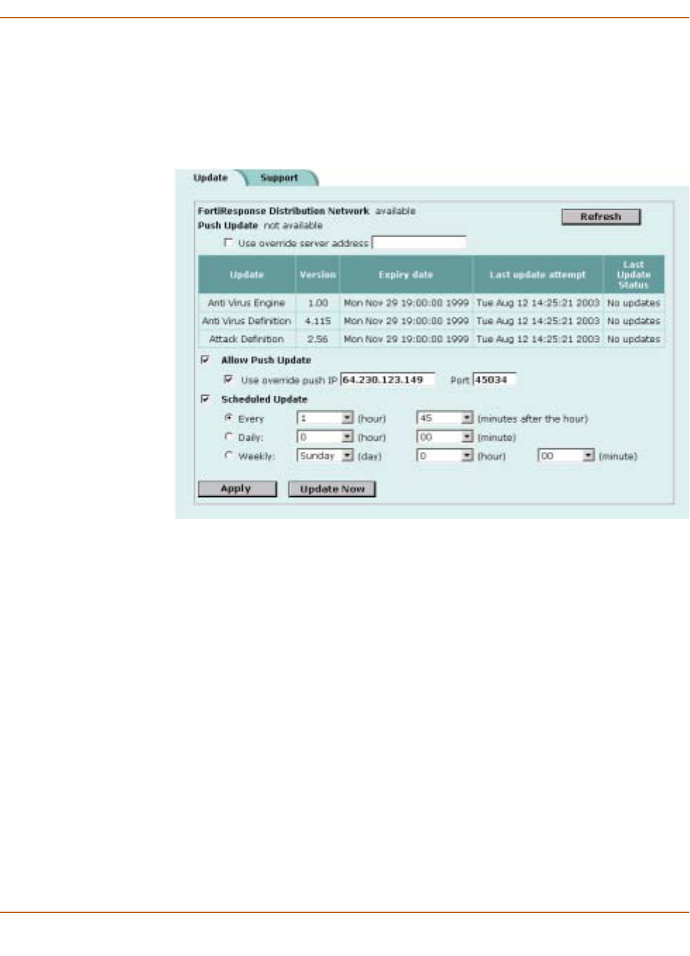
Virus and attack definitions updates and registration Scheduling updates
FortiWiFi-60 Installation and Configuration Guide 97
4Select Apply.
The FortiWiFi unit starts the next scheduled update according to the new update
schedule.
Whenever the FortiWiFi unit runs a scheduled update, the event is recorded in the
FortiWiFi event log.
Figure 1: Configuring automatic antivirus and attack definitions updates
Adding an override server
If you cannot connect to the FDN, or if your organization provides antivirus and attack
updates using their own FortiResponse server, you can use the following procedure to
add the IP address of an override FortiResponse server.
To add an override server
1Go to System > Update.
2Select the Use override server address check box.
3Type the IP address of a FortiResponse server.
4Select Apply.
The FortiWiFi unit tests the connection to the override server.
If the FortiResponse Distribution Network setting changes to available, the FortiWiFi
unit has successfully connected to the override server.
If the FortiResponse Distribution Network stays set to not available, the FortiWiFi unit
cannot connect to the override server. Check the FortiWiFi configuration and network
configuration for settings that would prevent the FortiWiFi unit connecting to the
override FortiResponse server.

98 Fortinet Inc.
Enabling push updates Virus and attack definitions updates and registration
Enabling scheduled updates through a proxy server
If your FortiWiFi unit must connect to the Internet through a proxy server, you can use
the set system autoupdate tunneling command to allow the FortiWiFi unit to
connect (or tunnel) to the FDN using the proxy server. Using this command you can
specify the IP address and port of the proxy server. As well, if the proxy server
requires authentication, you can add the user name and password required for the
proxy server to the autoupdate configuration. The full syntax for enabling updates
through a proxy server is:
set system autoupdate tunneling enable [address
<proxy-address_ip> [port <proxy-port> [username <username_str>
[password <password_str>]]]]
For example, if the IP address of the proxy server is 64.23.6.89 and its port is 8080,
enter the following command:
set system autouopdate tunneling enable address 64.23.6.89
port 8080
For more information about the set system autoupdate command, see Volume 6,
FortiGate CLI Reference Guide.
The FortiWiFi unit connects to the proxy server using the HTTP CONNECT method,
as described in RFC 2616. The FortiWiFi unit sends an HTTP CONNECT request to
the proxy server (optionally with authentication information) specifying the IP address
and port required to connect to the FDN. The proxy server establishes the connection
to the FDN and passes information between the FortiWiFi unit and the FDN.
The CONNECT method is used mostly for tunneling SSL traffic. Some proxy servers
do not allow the CONNECT to connect to any port; they restrict the allowed ports to
the well known ports for HTTPS and perhaps some other similar services. Because
FortiWiFi autoupdates use HTTPS on port 8890 to connect to the FDN, your proxy
server might have to be configured to allow connections on this port.
There are no special tunneling requirements if you have configured an override server
address to connect to the FDN.
Enabling push updates
The FDN can push updates to FortiWiFi units to provide the fastest possible response
to critical situations. You must register the FortiWiFi unit before it can receive push
updates. See “Registering the FortiWiFi unit” on page 105.
When you configure a FortiWiFi unit to allow push updates, the FortiWiFi unit sends a
SETUP message to the FDN. The next time a new antivirus engine, new antivirus
definitions, or new attack definitions are released, the FDN notifies all FortiWiFi units
that are configured for push updates that a new update is available. Within 60
seconds of receiving a push notification, the FortiWiFi unit requests an update from
the FDN.
Note: Push updates are not supported if the FortiWiFi unit must use a proxy server to connect
to the FDN. For more information, see “Enabling scheduled updates through a proxy server” on
page 98.

Virus and attack definitions updates and registration Enabling push updates
FortiWiFi-60 Installation and Configuration Guide 99
When the network configuration permits, configuring push updates is recommended in
addition to configuring scheduled updates. On average the FortiWiFi unit receives
new updates sooner through push updates than if the FortiWiFi unit receives only
scheduled updates. However, scheduled updates make sure that the FortiWiFi unit
receives the latest updates.
Enabling push updates is not recommended as the only method for obtaining updates.
The FortiWiFi unit might not receive the push notification. Also, when the FortiWiFi
unit receives a push notification it makes only one attempt to connect to the FDN and
download updates.
This section describes:
•Enabling push updates
•Push updates when FortiWiFi IP addresses change
•Enabling push updates through a NAT device
Enabling push updates
To enable push updates
1Go to System > Update.
2Select Allow Push Update.
3Select Apply.
Push updates when FortiWiFi IP addresses change
The SETUP message that the FortiWiFi unit sends when you enable push updates
includes the IP address of the FortiWiFi interface that the FDN connects to. If your
FortiWiFi unit is running in NAT/Route mode, the SETUP message includes the
FortiWiFi WAN1 IP address. If your FortiWiFi unit is running in Transparent mode, the
SETUP message includes the FortiWiFi management IP address. The FDN must be
able to connect to this IP address for your FortiWiFi unit to be able to receive push
update messages. If your FortiWiFi unit is behind a NAT device, see “Enabling push
updates through a NAT device” on page 100.
Whenever the WAN1 IP address of the FortiWiFi unit changes, the FortiWiFi unit
sends a new SETUP message to notify the FDN of the address change. As long as
the FortiWiFi unit sends this SETUP message and the FDN receives it, the FDN can
maintain the most up-to-date WAN1 IP address for the FortiWiFi unit.
The FortiWiFi unit sends the SETUP message if you change the WAN1 IP address
manually or if you have set the WAN1 interface addressing mode to DHCP or PPPoE
and your DHCP or PPPoE server changes the IP address.
If you have redundant connections to the Internet, the FortiWiFi unit also sends the
SETUP message when one Internet connection goes down and the FortiWiFi unit fails
over to the other Internet connection.
In Transparent mode if you change the management IP address, the FortiWiFi unit
also sends the SETUP message to notify the FDN of the address change.

100 Fortinet Inc.
Enabling push updates Virus and attack definitions updates and registration
Enabling push updates through a NAT device
If the FDN can connect to the FortiWiFi unit only through a NAT device, you must
configure port forwarding on the NAT device and add the port forwarding information
to the push update configuration. Using port forwarding, the FDN connects to the
FortiWiFi unit using either port 9443 or an override push port that you specify.
Example: push updates through a NAT device
This example describes how to configure a FortiWiFi NAT device to forward push
updates to a FortiWiFi unit installed on its internal network. For the FortiWiFi unit on
the internal network to receive push updates, the FortiWiFi NAT device must be
configured with a port forwarding virtual IP. This virtual IP maps the IP address of the
external interface of the FortiWiFi NAT device and a custom port to the IP address of
the FortiWiFi unit on the internal network. This IP address can either be the external
IP address of the FortiWiFi unit if it is operating in NAT/Route mode, or the
Management IP address of the FortiWiFi unit if it is operating in Transparent mode.
General procedure
Use the following steps to configure the FortiWiFi NAT device and the FortiWiFi unit
on the internal network so that the FortiWiFi unit on the internal network can receive
push updates:
1Add a port forwarding virtual IP to the FortiWiFi NAT device.
2Add a firewall policy to the FortiWiFi NAT device that includes the port forwarding
virtual IP.
3Configure the FortiWiFi unit on the internal network with an override push IP and port.
Note: You cannot receive push updates through a NAT device if the external IP address of the
NAT device is dynamic (for example, set using PPPoE or DHCP).
Note: This example describes the configuration for a FortiWiFi NAT device. However, you can
use any NAT device with a static external IP address that can be configured for port forwarding.
Note: Before completing the following procedure, you should register the internal network
FortiWiFi unit so that it can receive push updates.
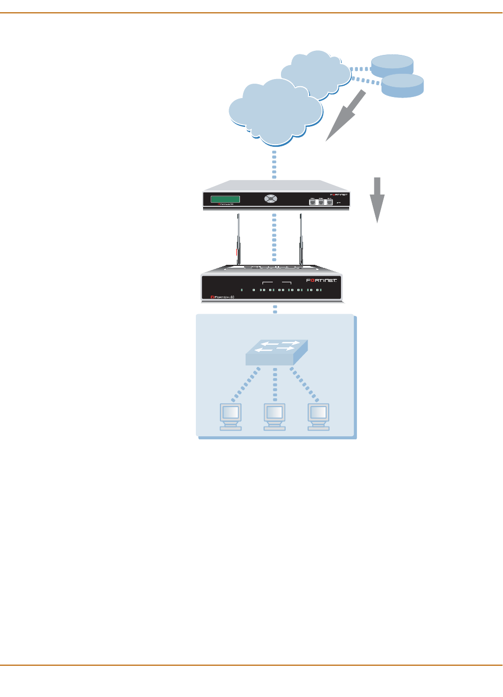
Virus and attack definitions updates and registration Enabling push updates
FortiWiFi-60 Installation and Configuration Guide 101
Figure 2: Example network topology: Push updates through a NAT device
Adding a port forwarding virtual IP to the FortiWiFi NAT device
Use the following procedure to configure a FortiWiFi NAT device to use port
forwarding to forward push update connections from the FDN to a FortiWiFi unit on
the internal network.
To configure the FortiWiFi NAT device
1Go to Firewall > Virtual IP.
2Select New.
3Type a name for the virtual IP.
4In the External Interface section, select the external interface that the FDN connects
to.
For the example topology, select the external interface.
Internet
Virtual IP maps
64.230.123.149:45001
to
192.168.1.99:9443
External IP
64.230.123.149
FortiResponse
Distribution
Network (FDN)
FortiWiFi-60A
Internal Network
Esc Enter
External IP or
Management IP
192.168.1.99
FortiGate-300
NAT Device
Push update to
IP address 64.230.123.149
and port 45001
INTERNAL
DMZ4321
LINK 100 LINK 100 LINK 100 LINK 100 LINK 100 LINK 100 LINK 100
WAN1 WA N2
PWR WLAN
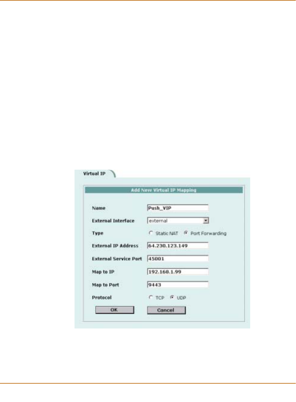
102 Fortinet Inc.
Enabling push updates Virus and attack definitions updates and registration
5In the Type section, select Port Forwarding.
6In the External IP Address section, type the external IP address that the FDN
connects to.
For the example topology, enter 64.230.123.149.
7Type the External Service Port that the FDN connects to.
For the example topology, enter 45001.
8In the Map to IP section, type the IP address of the FortiWiFi unit on the internal
network.
If the FortiWiFi unit is operating in NAT/Route mode, enter the IP address of the
external interface.
If the FortiWiFi unit is operating in Transparent mode, enter the management IP
address.
For the example topology, enter 192.168.1.99.
9Set the Map to Port to 9443.
10 Set Protocol to UDP.
11 Select OK.
Figure 3: Push update port forwarding virtual IP
Adding a firewall policy for the port forwarding virtual IP
To configure the FortiWiFi NAT device
1Add a new external to internal firewall policy.

Virus and attack definitions updates and registration Enabling push updates
FortiWiFi-60 Installation and Configuration Guide 103
2Configure the policy with the following settings:
3Select OK.
Configuring the FortiWiFi unit with an override push IP and port
To configure the FortiWiFi unit on the internal network
1Go to System > Update.
2Select the Allow Push Update check box.
3Select the Use override push check box.
4Set IP to the external IP address added to the virtual IP.
For the example topology, enter 64.230.123.149.
5Set Port to the external service port added to the virtual IP.
For the example topology, enter 45001.
6Select Apply.
The FortiWiFi unit sends the override push IP address and port to the FDN. The FDN
now uses this IP address and port for push updates to the FortiWiFi unit on the
internal network.
If the external IP address or external service port change, add the changes to the Use
override push configuration and select Apply to update the push information on the
FDN.
Figure 4: Example push update configuration
7Select Apply.
8You can select Refresh to make sure that push updates work.
Push Update changes to Available.
Source External_All
Destination The virtual IP added above.
Schedule Always
Service ANY
Action Accept
NAT Selected.

104 Fortinet Inc.
Registering FortiGate and FortiWiFi units Virus and attack definitions updates and registration
Registering FortiGate and FortiWiFi units
After purchasing and installing a new FortiWiFi unit, you can register the unit using the
web-based manager by going to System Update Support page, or by using a web
browser to connect to http://support.fortinet.com and selecting Product Registration.
Registration consists of entering your contact information and the serial numbers of
the FortiGate and FortiWiFi units that you or your organization purchased. You can
register multiple FortiGate and FortiWiFiunits in a single session without re-entering
your contact information.
Once registration is completed, Fortinet sends a Support Login user name and
password to your email address. You can use this user name and password to log on
to the Fortinet support web site to:
• View your list of registered FortiGate and FortiWiFi units
• Register additional FortiGate and FortiWiFi units
• Add or change FortiCare Support Contract numbers for each FortiGate and
FortiWiFi unit
• View and change registration information
• Download virus and attack definitions updates
• Download firmware upgrades
• Modify registration information after an RMA
Soon you will also be able to:
• Access Fortinet user documentation
• Access the Fortinet knowledge base
All registration information is stored in the Fortinet Customer Support database. This
information is used to make sure that your registered FortiGate and FortiWiFi units
can be kept up to date. All information is strictly confidential. Fortinet does not share
this information with any third-party organizations for any reason.
This section describes:
•FortiCare Service Contracts
•Registering the FortiWiFi unit
FortiCare Service Contracts
Owners of a new FortiGate and FortiWiFi unit are entitled to 90 days of technical
support services. To continue receiving support services after the 90-day expiry date,
you must purchase a FortiCare Support Contract from an authorized Fortinet reseller
or distributor. Different levels of service are available so you can purchase the support
that you need. For maximum network protection, Fortinet strongly recommends that
all customers purchase a service contract that covers antivirus and attack definition
updates. See your Fortinet reseller or distributor for details of packages and pricing.

Virus and attack definitions updates and registration Registering FortiGate and FortiWiFi units
FortiWiFi-60 Installation and Configuration Guide 105
To activate the FortiCare Support Contract, you must register the FortiGate and
FortiWiFi unit and add the FortiCare Support Contract number to the registration
information. You can also register the FortiGate and FortiWiFi unit without purchasing
a FortiCare Support Contract. In that case, when you purchase a FortiCare Support
Contract you can update the registration information to add the support contract
number.
A single FortiCare Support Contract can cover multiple FortiGate and FortiWiFi units.
You must enter the same service contract number for each of the FortiGate and
FortiWiFi models covered by the service contract.
Registering the FortiWiFi unit
Before registering a FortiWiFi unit, you require the following information:
• Your contact information including:
• First and last name
• Company name
• Email address (Your Fortinet support login user name and password will be
sent to this email address.)
•Address
• Contact phone number
• A security question and an answer to the security question.
This information is used for password recovery. The security question should be a
simple question that only you know the answer to. The answer should not be easy
to guess.
• The product model and serial number for each FortiWiFi unit that you want to
register.
The serial number is located on a label on the bottom of the FortiWiFi unit.
You can view the Serial number from the web-based manager by going to
System > Status.
The serial number is also available from the CLI using the get system status
command.
• FortiCare Support Contract numbers, if you purchased FortiCare Support
Contracts for the FortiWiFi units that you want to register.
To register one or more FortiWiFi units
1Go to System > Update > Support.
2Enter your contact information on the product registration form.
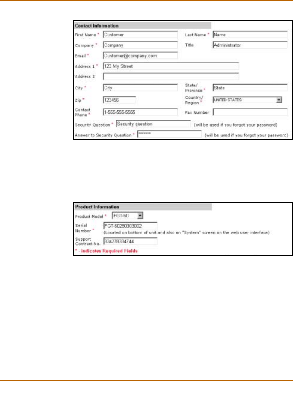
106 Fortinet Inc.
Registering FortiGate and FortiWiFi units Virus and attack definitions updates and registration
Figure 5: Registering a FortiWiFi unit (contact information and security question)
3Provide a security question and an answer to the security question.
4Select the model number of the Product Model to register.
5Enter the Serial Number of the FortiWiFi unit.
6If you have purchased a FortiCare Support Contract for this FortiWiFi unit, enter the
support contract number.
Figure 6: Registering a FortiGate unit (product information)
7Select Finish.
If you have not entered a FortiCare Support Contract number (SCN) you can return to
the previous page to enter the number. If you do not have a FortiCare Support
Contract, you can select Continue to complete the registration.
If you have entered a support contract number, a real-time validation is performed to
verify that the SCN information matches the FortiWiFi unit. If the information does not
match you can try entering it again.
A web page is displayed that contains detailed information about the Fortinet technical
support services available to you for the registered FortiWiFi unit.
Your Fortinet support user name and password is sent to the email address provided
with your contact information.

Virus and attack definitions updates and registration Updating registration information
FortiWiFi-60 Installation and Configuration Guide 107
Updating registration information
You can use your Fortinet support user name and password to log on to the Fortinet
Support web site at any time to view or update your Fortinet support information.
This section describes:
•Recovering a lost Fortinet support password
•Viewing the list of registered FortiGate and FortiWiFi units
•Registering a new FortiWiFi unit
•Adding or changing a FortiCare Support Contract number
•Changing your Fortinet support password
•Changing your contact information or security question
•Downloading virus and attack definitions updates
Recovering a lost Fortinet support password
If you provided a security question and answer when you registered on the Fortinet
support web site, you can use the following procedure to receive a replacement
password. If you did not provide a security question and answer, contact Fortinet
technical support.
To recover a lost Fortinet support password
1Go to System > Update > Support.
2Select Support Login.
3Enter your Fortinet support user name.
4Select Forgot your password?
5Enter your email address and select Submit.
The security question that you entered when you registered is displayed.
6Enter the answer to your security question and select Get Password.
If you entered the correct answer to the security question, an email containing a new
password is sent to your email address. You can use your current user name and this
password to log into the Fortinet support web site.
7Select Support Login.
8When you receive your new password, enter your user name and new password to
log into the Fortinet support web site.
Viewing the list of registered FortiGate and FortiWiFi units
To view the list of registered FortiGate units
1Go to System > Update > Support.
2Select Support Login.
3Enter your Fortinet support user name and password.
4Select Login.
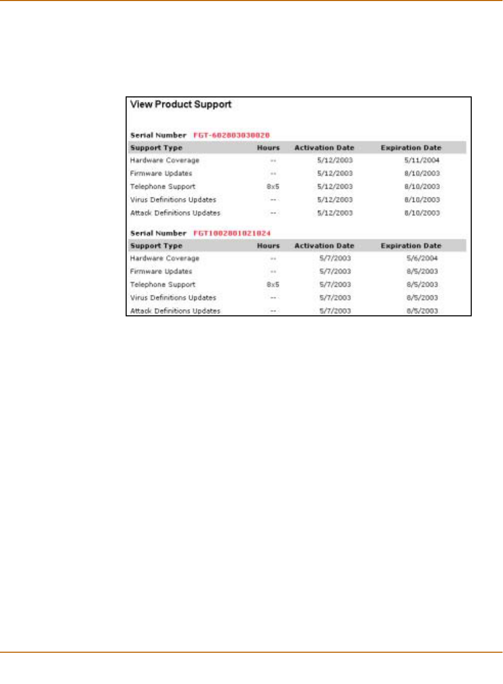
108 Fortinet Inc.
Updating registration information Virus and attack definitions updates and registration
5Select View Products.
The list of FortiGate products that you have registered is displayed. For each
FortiGate unit, the list includes the serial number and current support options for that
unit.
Figure 7: Sample list of registered FortiGate units
Registering a new FortiWiFi unit
To register a new FortiWiFi unit
1Go to System > Update > Support.
2Select Support Login.
3Enter your Fortinet support user name and password.
4Select Login.
5Select Add Registration.
6Select the model number of the product model that you want to register.
7Enter the serial number of the FortiWiFi unit.
8If you have purchased a FortiCare Support Contract for this FortiWiFi unit, enter the
support contract number.
9Select Finish.
The list of FortiWiFi products that you have registered is displayed. The list now
includes the new FortiWiFi unit.
Adding or changing a FortiCare Support Contract number
To add or change a FortiCare Support Contract number
1Go to System > Update > Support.

Virus and attack definitions updates and registration Updating registration information
FortiWiFi-60 Installation and Configuration Guide 109
2Select Support Login.
3Enter your Fortinet support user name and password.
4Select Login.
5Select Add/Change Contract number.
6Select the Serial Number of the FortiWiFi unit for which to add or change a FortiCare
Support Contract number.
7Add the new Support Contract number.
8Select Finish.
The list of FortiGate products that you have registered is displayed. The list now
includes the new support contract information.
Changing your Fortinet support password
To change your Fortinet support password
1Go to System > Update > Support.
2Select Support Login.
3Enter your Fortinet support user name and password.
4Select Login.
5Select My Profile.
6Select Change Password.
7Enter your current password.
8Enter and confirm a new password.
An email is sent to your email address confirming that your password has been
changed. Use your current user name and new password the next time you log into
the Fortinet technical support web site.
Changing your contact information or security question
To change your contact information or security question
1Go to System > Update > Support.
2Select Support Login.
3Enter your Fortinet support user name and password.
4Select Login.
5Select My Profile.
6Select Edit Profile.
7Make the required changes to your contact information.
8Make the required changes to your security question and answer.
9Select Update Profile.
Your changes are saved to the Fortinet technical support database. If you changed
your contact information, the changes are displayed.
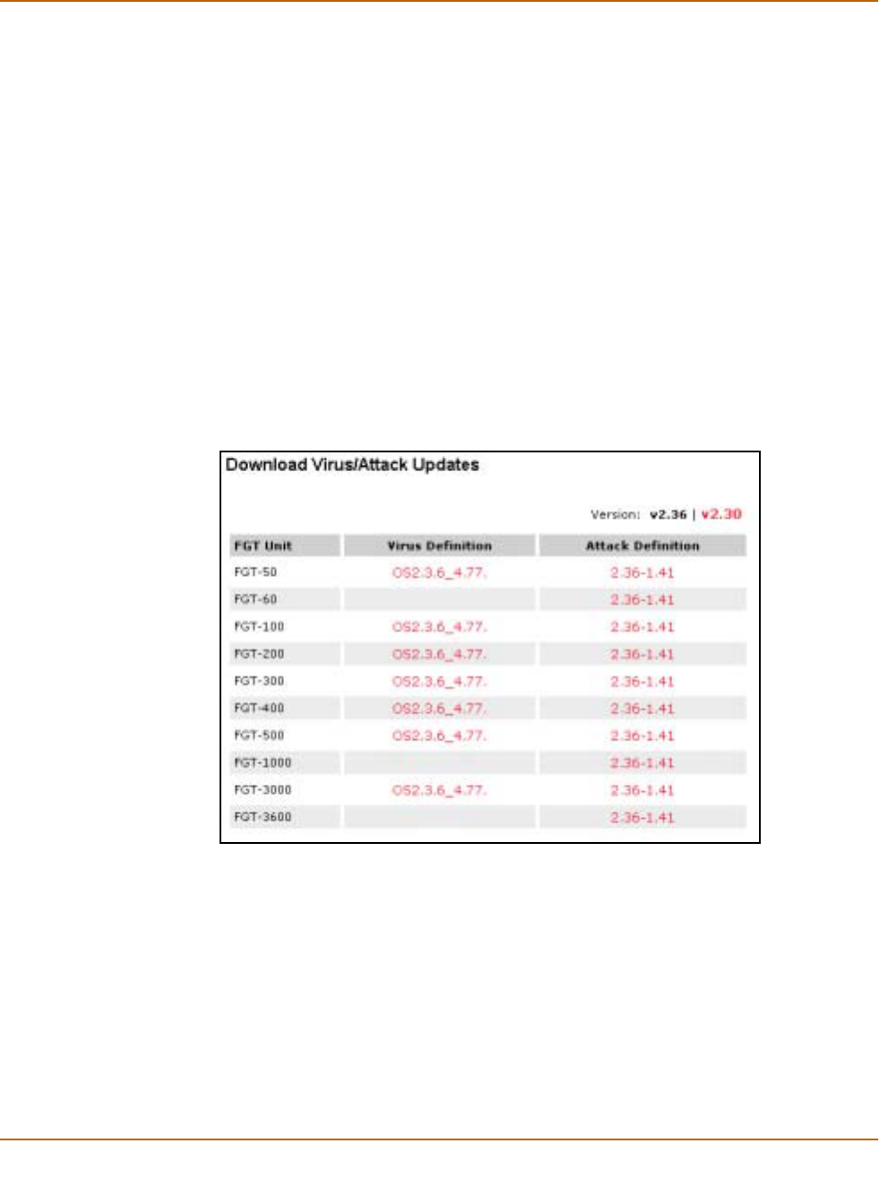
110 Fortinet Inc.
Registering a FortiWiFi unit after an RMA Virus and attack definitions updates and registration
Downloading virus and attack definitions updates
Use the following procedure to manually download virus and attack definitions
updates. This procedure also describes how to install the attack definitions updates on
your FortiWiFi unit.
To download virus and attack definitions updates
1Go to System > Update > Support.
2Select Support Login.
3Enter your Fortinet support user name and password.
4Select Login.
5Select Download Virus/Attack Update.
6If required, select the FortiOS version.
7Select the virus and attack definitions to download.
Figure 8: Downloading virus and attack definition updates
For information about how to install the downloaded files, see “Manual virus definition
updates” on page 82 and “Manual attack definition updates” on page 83.
Registering a FortiWiFi unit after an RMA
The Return Material Authorization (RMA) process starts when a registered FortiWiFi
unit does not work properly because of a hardware failure. If this happens while the
FortiWiFi unit is protected by hardware coverage, you can return the FortiWiFi unit
that is not functioning to your reseller or distributor.

Virus and attack definitions updates and registration Registering a FortiWiFi unit after an RMA
FortiWiFi-60 Installation and Configuration Guide 111
The RMA is recorded and you will receive a replacement unit. Fortinet adds the RMA
information to the Fortinet support database. When you receive the replacement unit
you can use the following procedure to update your product registration information.
To register a FortiWiFi unit after an RMA
1Go to System > Update > Support.
2Select Support Login.
3Enter your Fortinet support user name and password to log in.
4Select Add Registration.
5Select the link to replace a unit with a new unit from an RMA.
6Select Finish.
The list of FortiGate products that you have registered is displayed. The list now
includes the replacement FortiGate unit. All support levels are transferred to the
replacement unit.

112 Fortinet Inc.
Registering a FortiWiFi unit after an RMA Virus and attack definitions updates and registration

FortiWiFi-60 Installation and Configuration Guide Version 2.50
FortiWiFi-60 Installation and Configuration Guide 113
Network configuration
You can use the System Network page to change any of the following FortiWiFi
network settings:
•Configuring interfaces
•Adding DNS server IP addresses
•Configuring routing
•Configuring DHCP services
•Configuring the modem interface
•Wireless configuration
Configuring interfaces
Use the following procedures to configure FortiWiFi interfaces:
•Viewing the interface list
•Changing the administrative status of an interface
•Configuring an interface with a manual IP address
•Configuring an interface for DHCP
•Configuring an interface for PPPoE
•Adding a secondary IP address to an interface
•Adding a ping server to an interface
•Controlling administrative access to an interface
•Changing the MTU size to improve network performance
•Configuring traffic logging for connections to an interface
•Configuring the management interface in Transparent mode
•Wireless configuration
For information about configuring the modem interface, see “Configuring the modem
interface” on page 129.

114 Fortinet Inc.
Configuring interfaces Network configuration
Viewing the interface list
To view the interface list
1Go to System > Network > Interface.
The interface list is displayed. The interface list shows the following status information
for all the FortiWiFi interfaces and VLAN subinterfaces:
• The name of the interface
• The IP address of the interface
• The netmask of the interface
• The administrative access configuration for the interface
See “Controlling administrative access to an interface” on page 117 for information
about administrative access options.
• The administrative status for the interface
If the administrative status is a green arrow, the interface is up and can accept
network traffic. If the administrative status is a red arrow, the interface is
administratively down and cannot accept traffic. To change the administrative
status, see “Changing the administrative status of an interface” on page 114.
For the modem interface, status indicates whether or not the modem is connected
to a dialup account. If status is a green arrow, the modem is connected. If status is
a red arrow, the modem is not connected. For more information about the modem
interface, see “Configuring the modem interface” on page 129.
Changing the administrative status of an interface
You can use the following procedures to start an interface that is administratively
down and stop and interface that is administratively up.
You cannot use the following procedures for the modem interface.
To start up an interface that is administratively down
1Go to System > Network > Interface.
The interface list is displayed.
2Select Bring Up for the interface that you want to start.
To stop an interface that is administratively up
1From the FortiWiFi CLI, enter the command:
set system interface <intf_str> config status down
You can only stop an interface that is administratively up from the FortiWiFi command
line interface (CLI).
Configuring an interface with a manual IP address
You can change the static IP address of any FortiWiFi interface.
To change an interface with a manual IP address
1Go to System > Network > Interface.
2Choose an interface and select Modify .

Network configuration Configuring interfaces
FortiWiFi-60 Installation and Configuration Guide 115
3Set Addressing Mode to Manual.
4Change the IP address and Netmask as required.
The IP address of the interface must be on the same subnet as the network the
interface is connecting to.
Two interfaces cannot have the same IP address and cannot have IP addresses on
the same subnet.
5Select OK to save your changes.
If you changed the IP address of the interface to which you are connecting to manage
the FortiWiFi unit, you must reconnect to the web-based manager using the new
interface IP address.
Configuring an interface for DHCP
You can configure any FortiWiFi interface to use DHCP.
If you configure the interface to use DHCP, the FortiWiFi unit automatically broadcasts
a DHCP request. You can disable connect to server if you are configuring the
FortiWiFi unit offline and you do not want the FortiWiFi unit to send the DHCP request.
By default, the FortiWiFi unit also retrieves a default gateway IP address and DNS
server IP addresses from the DHCP server. You can disable the option Retrieve
default gateway and DNS from server if you do not want the DHCP server to configure
these FortiWiFi settings.
To configure an interface for DHCP
1Go to System > Network > Interface.
2Choose an interface and select Modify .
3In the Addressing Mode section, select DHCP.
4Clear the Retrieve default gateway and DNS from server check box if you do not want
the FortiWiFi unit to obtain a default gateway IP address and DNS server IP
addresses from the DHCP server.
By default, this option is enabled.
5Clear the Connect to Server check box if you do not want the FortiWiFi unit to connect
to the DHCP server.
By default, this option is enabled.
6Select Apply.
The FortiWiFi unit attempts to contact the DHCP server from the interface to set the IP
address, netmask, default gateway IP address, and DNS server IP addresses.
7Select Status to refresh the addressing mode status message.
8Select OK.
initializing No activity
connecting The FortiWiFi unit is attempting to connect to the DHCP server.
connected The FortiWiFi unit retrieves an IP address, netmask, and other settings from
the DHCP server.
failed The FortiWiFi unit was unable to retrieve an IP address and other
information from the DHCP server.

116 Fortinet Inc.
Configuring interfaces Network configuration
Configuring an interface for PPPoE
Use the following procedure to configure any FortiWiFi interface to use PPPoE.
If you configure the interface to use PPPoE, the FortiWiFi unit automatically
broadcasts a PPPoE request. You can disable connect to server if you are configuring
the FortiWiFi unit offline and you do not want the FortiWiFi unit to send the PPPoE
request.
By default, the FortiWiFi unit also retrieves a default gateway IP address and DNS
server IP addresses from the PPPoE server. You can disable the option Retrieve
default gateway and DNS from server if you do not want the PPPoE server to
configure these FortiWiFi settings.
To configure an interface for PPPoE
1Go to System > Network > Interface.
2Choose an interface and select Modify .
3In the Addressing Mode section, select PPPoE.
4Enter your PPPoE account User Name and Password.
5Clear the Retrieve default gateway and DNS from server check box if you do not want
the FortiWiFi unit to obtain a default gateway IP address and DNS server IP
addresses from the PPPoE server.
By default, this option is enabled.
6Clear the Connect to Server check box if you do not want the FortiWiFi unit to connect
to the PPPoE server.
By default, this option is enabled.
7Select Apply.
The FortiWiFi unit attempts to contact the PPPoE server from the interface to set the
IP address, netmask, default gateway IP address, and DNS server IP addresses.
8Select Status: to refresh the addressing mode status message. Possible messages:
9Select OK.
Adding a secondary IP address to an interface
You can use the CLI to add a secondary IP address to any FortiWiFi interface. The
secondary IP address cannot be the same as the primary IP address but it can be on
the same subnet.
To add a secondary IP address from the CLI enter the command:
set system interface <intf_str> config secip <second_ip>
<netmask_ip>
initializing No activity
connecting The FortiWiFi unit is attempting to connect to the DHCP server.
connected The FortiWiFi unit retrieves an IP address, netmask, and other settings from
the PPPoE server.
failed The FortiWiFi unit was unable to retrieve an IP address and other
information from the PPPoE server.

Network configuration Configuring interfaces
FortiWiFi-60 Installation and Configuration Guide 117
You can also configure management access and add a ping server to the secondary
IP address.
set system interface <intf_str> config secallowaccess ping
https ssh snmp http telnet
set system interface <intf_str> config secgwdetect enable
Adding a ping server to an interface
Add a ping server to an interface if you want the FortiWiFi unit to confirm connectivity
with the next hop router on the network connected to the interface. Adding a ping
server is required for routing failover. See “Adding destination-based routes to the
routing table” on page 123.
To add a ping server to an interface
1Go to System > Network > Interface.
2Choose an interface and select Modify .
3Set Ping Server to the IP address of the next hop router on the network connected to
the interface.
4Select the Enable check box.
The FortiWiFi unit uses dead gateway detection to ping the Ping Server IP address to
make sure that the FortiWiFi unit can connect to this IP address. To configure dead
gateway detection, see “Modifying the Dead Gateway Detection settings” on
page 145.
5Select OK to save the changes.
Controlling administrative access to an interface
For a FortiWiFi unit running in NAT/Route mode, you can control administrative
access to an interface to control how administrators access the FortiWiFi unit and the
FortiWiFi interfaces to which administrators can connect.
Controlling administrative access for an interface connected to the Internet allows
remote administration of the FortiWiFi unit from any location on the Internet. However,
allowing remote administration from the Internet could compromise the security of
your FortiWiFi unit. You should avoid allowing administrative access for an interface
connected to the Internet unless this is required for your configuration. To improve the
security of a FortiWiFi unit that allows remote administration from the Internet:
• Use secure administrative user passwords,
• Change these passwords regularly,
• Enable secure administrative access to this interface using only HTTPS or SSH,
• Do not change the system idle timeout from the default value of 5 minutes (see “To
set the system idle timeout” on page 144).
To configure administrative access in Transparent mode, see “Configuring the
management interface in Transparent mode” on page 119.
To control administrative access to an interface
1Go to System > Network > Interface.

118 Fortinet Inc.
Configuring interfaces Network configuration
2Choose an interface and select Modify .
3Select the Administrative Access methods for the interface.
4Select OK to save the changes.
Changing the MTU size to improve network performance
To improve network performance, you can change the maximum transmission unit
(MTU) of the packets that the FortiWiFi unit transmits from any interface. Ideally, this
MTU should be the same as the smallest MTU of all the networks between the
FortiWiFi unit and the destination of the packets. If the packets that the FortiWiFi unit
sends are larger, they are broken up or fragmented, which slows down transmission.
Experiment by lowering the MTU to find an MTU size for best network performance.
To change the MTU size of the packets leaving an interface
1Go to System > Network > Interface.
2Choose an interface and select Modify .
3Select Override default MTU value (1500).
4Set the MTU size.
Set the maximum packet size. For manual and DHCP addressing mode the MTU size
can be from 576 to 1500 bytes. For PPPoE addressing mode the MTU size can be
from 576 to 1492 bytes.
Configuring traffic logging for connections to an interface
To configure traffic logging for connections to an interface
1Go to System > Network > Interface.
2Choose an interface and select Modify .
3Select the Log check box to record log messages whenever a firewall policy accepts a
connection to this interface.
4Select OK to save the changes.
HTTPS To allow secure HTTPS connections to the web-based manager through this
interface.
PING If you want this interface to respond to pings. Use this setting to verify your
installation and for testing.
HTTP To allow HTTP connections to the web-based manager through this interface.
HTTP connections are not secure and can be intercepted by a third party.
SSH To allow SSH connections to the CLI through this interface.
SNMP To allow a remote SNMP manager to request SNMP information by connecting to
this interface. See “Configuring SNMP” on page 147.
TELNET To allow Telnet connections to the CLI through this interface. Telnet connections
are not secure and can be intercepted by a third party.

Network configuration Configuring interfaces
FortiWiFi-60 Installation and Configuration Guide 119
Configuring the management interface in Transparent mode
Configure the management interface in Transparent mode to set the management IP
address of the FortiWiFi unit. Administrators connect to this IP address to administer
the FortiWiFi unit. The FortiWiFi also uses this IP address to connect to the FDN for
virus and attack updates (see “Updating antivirus and attack definitions” on page 93).
You can also configure the management interface to control how administrators
connect to the FortiWiFi unit for administration and the FortiWiFi interfaces to which
administrators can connect.
Controlling administrative access to a FortiWiFi interface connected to the Internet
allows remote administration of the FortiWiFi unit from any location on the Internet.
However, allowing remote administration from the Internet could compromise the
security of the FortiWiFi unit. You should avoid allowing administrative access for an
interface connected to the Internet unless this is required for your configuration. To
improve the security of a FortiWiFi unit that allows remote administration from the
Internet:
• Use secure administrative user passwords,
• Change these passwords regularly,
• Enable secure administrative access to this interface using only HTTPS or SSH,
• Do not change the system idle timeout from the default value of 5 minutes (see “To
set the system idle timeout” on page 144).
To configure the management interface in Transparent mode
1Go to System > Network > Management.
2Change the Management IP and Netmask as required.
This must be a valid IP address for the network that you want to manage the FortiWiFi
unit from.
3Add a default gateway IP address if the FortiWiFi unit must connect to a default
gateway to reach the management computer.
4Select the administrative access methods for each interface.
5Select Log for each interface that you want to record log messages whenever a
firewall policy accepts a connection to this interface.
6Select Apply to save the changes.
HTTPS To allow secure HTTPS connections to the web-based manager through this
interface.
PING If you want this interface to respond to pings. Use this setting to verify your
installation and for testing.
HTTP To allow HTTP connections to the web-based manager through this interface.
HTTP connections are not secure and can be intercepted by a third party.
SSH To allow SSH connections to the CLI through this interface.
SNMP To allow a remote SNMP manager to request SNMP information by connecting to
this interface. See “Configuring SNMP” on page 147.
TELNET To allow Telnet connections to the CLI through this interface. Telnet connections
are not secure and can be intercepted by a third party.

120 Fortinet Inc.
Configuring interfaces Network configuration
Wireless configuration
You can configure the FortiWiFi-60 WLAN interface so that users with wireless
network cards can connect to this interface. From this wireless network users can
connect through the FortiWiFi-60 to the Internet or to internal or DMZ networks.
The FortiWiFi-60 supports the following wireless network standards:
• IEEE 802.11b (2.4-GHz Band)
• IEEE 802.11g (2.4-GHz Band)
• Wired Equivalent Privacy (WEP)
To configure wireless settings
Configure wireless settings to select the country or region in which you are operating
the FortiWiFi-60 and select the channel to use. You can also enable WEP, enter a
WEP key, and change the SSID that the FortiWiFi-60 broadcasts.
1Go to System > Network > Interface.
2For the wlan interface, select Modify .
3Set Geography to your country or region.
4Select a channel number for your FortiWiFi-60 wireless network.
Users who wish to use the FortiWiFi-60 wireless network should configure their
computers to use this channel for wireless networking.
5Set security to WEP and enter a WEP key.
The key can be up to 26 hexidecimal digits (0-9 a-f).
6Change the Service Set ID (SSID) as required.
The SSID is the wireless network name that the FortiWiFi-60 broadcasts. Users who
wish to use to the FortiWiFi-60 wireless network should configure their computers to
connect to the network that broadcasts this network name.
7Select OK.

Network configuration Configuring interfaces
FortiWiFi-60 Installation and Configuration Guide 121
Table 2: IEEE 802.11b (2.4-GHz Band) channel numbers
Channel
number Frequency
(MHz)
Regulatory Areas
Americas EMEA Israel Japan
12412 X X – X
22417 X X – X
32422 X X – X
42427 X X – X
52432XXXX
62437XXXX
72442XXXX
82447XXXX
92452 X X – X
10 2457 X X – X
11 2462 X X – X
12 2467–X–X
13 2472–X–X
14 2484 – – – X
Mexico is included in the Americas regulatory domain. Channels 1 through 8 are for indoor
use only. Channels 9 through 11 can be used indoors and outdoors. You must make sure that
the channel number complies with the regulatory standards of Mexico.
Table 3: IEEE 802.11g (2.4-GHz Band) channel numbers
Channel
number Frequency
(MHz)
Regulatory Areas
Americas EMEA Israel Japan
CCK ODFM CCK ODFM CCK ODFM CCK ODFM
12412 XXXX––XX
22417 XXXX––XX
32422 XXXX––XX
42427 XXXX––XX
52432 XXXXXXXX
62437 XXXXXXXX
72442 XXXXXXXX
82447 XXXXXXXX
92452 XXXX––XX
10 2457 XXXX––XX
11 2462 XXXX––XX
12 2467 ––XX––XX
13 2472 ––XX––XX
14 2484––––––X–

122 Fortinet Inc.
Adding DNS server IP addresses Network configuration
Adding DNS server IP addresses
Several FortiWiFi functions, including sending email alerts and URL blocking, use
DNS. Use the following procedure to add the IP addresses of the DNS servers that
your FortiWiFi unit can connect to. DNS server IP addresses are usually supplied by
your ISP.
To add DNS server IP addresses
1Go to System > Network > DNS.
2Change the primary and secondary DNS server IP addresses as required.
3Select Apply to save the changes.
Configuring routing
This section describes how to configure FortiWiFi routing. You can configure routing to
add static routes from the FortiWiFi unit to local routers. Using policy routing you can
increase the flexibility of FortiWiFi routing to support more advanced routing functions.
You can also use routing to create a multiple Internet connection configuration that
supports redundancy and load sharing between the two Internet connections.
This section describes:
•Adding a default route
•Adding destination-based routes to the routing table
•Adding routes in Transparent mode
•Configuring the routing table
•Policy routing
Adding a default route
You can add a default route for network traffic leaving the external interface.
To add a default route
1Go to System > Network > Routing Table.
2Select New to add a new route.
3Set the Source IP and Netmask to 0.0.0.0.
4Set the Destination IP and Netmask to 0.0.0.0.
5Set Gateway 1 to the IP address of the routing gateway that routes traffic to the
Internet.
6Select OK to save the default route.
Note: Only one default route can be active at a time. If two default routes are added to the
routing table, only the default route closest to the top of the routing table is active.

Network configuration Configuring routing
FortiWiFi-60 Installation and Configuration Guide 123
Adding destination-based routes to the routing table
You can add destination-based routes to the FortiWiFi routing table to control the
destination of traffic exiting the FortiWiFi unit. You configure routes by adding
destination IP addresses and netmasks and adding gateways for these destination
addresses. The gateways are the next hop routers to which to route traffic that
matches the destination addresses in the route.
You can add one or two gateways to a route. If you add one gateway, the FortiWiFi
unit routes the traffic to that gateway. You can add a second gateway to route traffic to
the second gateway if the first gateway fails.
To support routing failover, the IP address of each gateway must be added to the ping
server of the interface connected to the same network as the gateway. For information
about adding a ping server, see “Adding a ping server to an interface” on page 117.
To add destination-based routes to the routing table
1Go to System > Network > Routing Table.
2Select New to add a new route.
3Type the Destination IP address and netmask for the route.
4Add the IP address of Gateway #1.
Gateway #1 is the IP address of the primary destination for the route.
Gateway #1 must be on the same subnet as a FortiWiFi interface.
If you are adding a static route from the FortiWiFi unit to a single destination router,
you need to specify only one gateway.
5Add the IP address of Gateway #2, if you want to route traffic to multiple gateways.
6Set Device #1 to the FortiWiFi interface through which you want to route traffic to
connect to Gateway #1.
You can select the name of an interface or Auto (the default). If you select the name of
an interface, the traffic is routed to that interface. If you select Auto the system selects
the interface according to the following rules:
• If the Gateway #1 IP address is on the same subnet as a FortiWiFi interface, the
system sends the traffic to that interface.
• If the Gateway #1 IP address is not on the same subnet as a FortiWiFi interface,
the system routes the traffic to the WAN1 interface, using the default route.
You can use Device #1 to send packets to an interface that is on a different subnet
than the destination IP address of the packets without routing them using the default
route.

124 Fortinet Inc.
Configuring routing Network configuration
7Set Device #2 to the FortiWiFi interface through which to route traffic to connect to
Gateway #2.
You can select the name of an interface or Auto (the default). If you select the name of
an interface, the traffic is routed to that interface. If you select Auto the system selects
the interface according to the following rules:
• If the Gateway #2 IP address is on the same subnet as a FortiWiFi interface, the
system sends the traffic to that interface.
• If the Gateway #2 IP address is not on the same subnet as a FortiWiFi interface,
the system routes the traffic to the WAN1 interface, using the default route.
You can use Device #2 to send packets to an interface that is on a different subnet
than the destination IP address of the packets without routing them using the default
route.
8Select OK to save the route.
Adding routes in Transparent mode
Use the following procedure to add routes when operating the FortiWiFi unit in
Transparent mode.
To add a route in Transparent mode
1Go to System > Network > Routing.
2Select New.
3Enter the Destination IP address and Netmask for the route.
4Enter the Gateway IP address for the route.
5Select OK to save the new route.
6Repeat steps 1 to 5 to add more routes as required.
Configuring the routing table
The routing table shows the destination IP address and mask of each route that you
add, as well as the gateways and devices added to the route. The routing table also
displays the gateway connection status. A green check mark indicates that the
FortiWiFi unit has used the ping server and dead gateway detection to determine that
it can connect to the gateway. A red X means that a connection cannot be established.
A blue question mark means that the connection status is unknown. For more
information, see “Adding a ping server to an interface” on page 117.
The FortiWiFi unit assigns routes using a best match algorithm based on the
destination address of the packet and the destination address of the route. To select a
route for a packet, the FortiWiFi unit searches the routing table for a route that best
matches the destination address of the packet. If a match is not found, the FortiWiFi
unit routes the packet using the default route.
Note: Any two routes in the routing table must differ by something other than just the gateway to
be simultaneously active. If two routes added to the routing table are identical except for their
gateway IP addresses, only the route closer to the top of the routing table can be active.
Note: Arrange routes in the routing table from more specific to more general. For information
about arranging routes in the routing table, see “Configuring the routing table”.
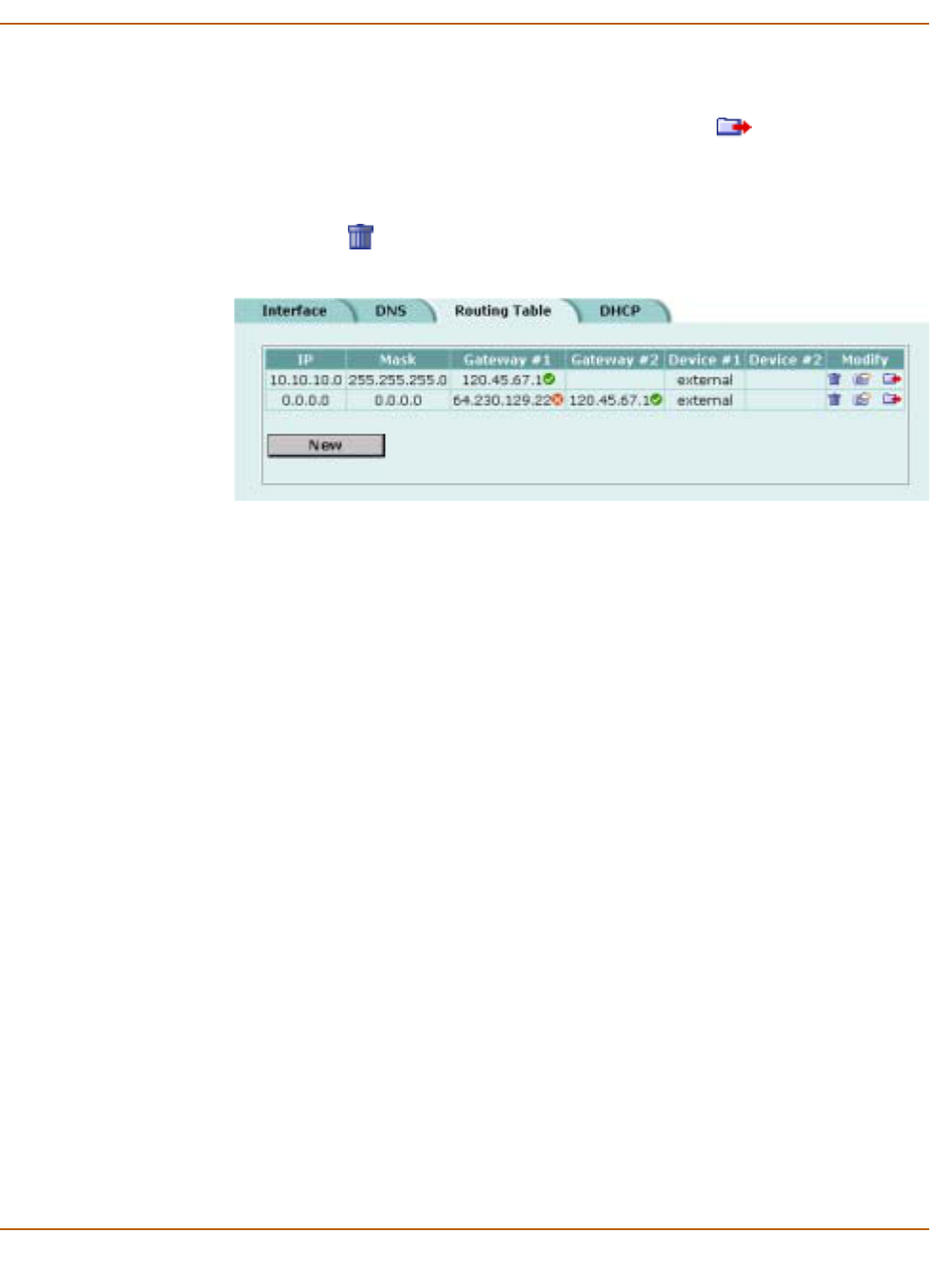
Network configuration Configuring routing
FortiWiFi-60 Installation and Configuration Guide 125
To configure the routing table
1Go to System > Network > Routing Table.
2Choose the route that you want to move and select Move to to change its order in
the routing table.
3Type a number in the Move to field to specify where in the routing table to move the
route and select OK.
4Select Delete to delete a route from the routing table.
Figure 9: Routing table
Policy routing
Policy routing extends the functions of destination routing. Using policy routing you
can route traffic based on the following:
• Destination address
• Source address
• Protocol, service type, or port range
• Incoming or source interface
Using policy routing you can build a routing policy database (RPDB) that selects the
appropriate route for traffic by applying a set of routing rules. To select a route for
traffic, the FortiWiFi unit matches the traffic with the policy routes added to the RPDB
starting at the top of the list. The first policy route that matches is used to set the route
for the traffic. The route supplies the next hop gateway as well as the FortiWiFi
interface to be used by the traffic.
Packets are matched with policy routes before they are matched with destination
routes. If a packet does not match a policy route, it is routed using destination routes.
The gateway added to a policy route must also be added to a destination route. When
the FortiWiFi unit matches packets with a route in the RPDB, the FortiWiFi unit looks
in the destination routing table for the gateway that was added to the policy route. If a
match is found, the FortiWiFi unit routes the packet using the matched destination
route. If a match is not found, the FortiWiFi unit routes the packet using normal
routing.
To find a route with a matching gateway, the FortiWiFi unit starts at the top of the
destination routing table and searches until it finds the first matching destination route.
This matched route is used to route the packet.
For policy routing examples, see “Policy routing examples” on page 56.

126 Fortinet Inc.
Configuring DHCP services Network configuration
Policy routing command syntax
Configure policy routing using the following CLI command.
set system route policy <route_int> src <source_ip>
<source_mask> iifname <source-interface_name>
dst <destination_ip> <destination_mask>
oifname <destination-interface_name> protocol <protocol_int>
port <low-port_int> <high-port_int> gw <gateway_ip>
Complete policy routing command syntax is described in Volume 6: FortiGate CLI
Reference Guide.
Configuring DHCP services
You can configure DHCP server or DHCP relay agent functionality on any FortiWiFi
interface.
A FortiWiFi interface can act as either a DHCP server or as a DHCP relay agent. An
interface cannot provide both functions.
This section describes the following:
•Configuring a DHCP relay agent
•Configuring a DHCP server
Configuring a DHCP relay agent
In a DHCP relay configuration, the FortiWiFi unit forwards DHCP requests from DHCP
clients through the FortiWiFi unit to a DHCP server. The FortiWiFi unit also returns
responses from the DHCP server to the DHCP clients. The DHCP server must have a
route to the FortiWiFi unit that is configured as the DHCP relay so that the packets
sent by the DHCP server to the DHCP client arrive at the FortiWiFi performing DHCP
relay.
To configure an interface as a DHCP relay agent
1Go to System > Network > DHCP.
2Select Service.
3Select the interface to be the DHCP relay agent.
4Select DHCP Relay Agent.
5Enter the DHCP Server IP address.
6Select Apply.
Note: To configure DHCP server or DHCP relay functionality on an interface, the FortiWiFi unit
must be in NAT/Route mode and the interface must have a static IP address.

Network configuration Configuring DHCP services
FortiWiFi-60 Installation and Configuration Guide 127
Configuring a DHCP server
As a DHCP server, the FortiWiFi unit dynamically assigns IP addresses to hosts
located on connected subnets. You can configure a DHCP server for any FortiWiFi
interface. You can also configure a DHCP server for more than one FortiWiFi
interface. For each DHCP server configuration you can add multiple scopes (also
called address scopes) so that the DHCP server can assign IP addresses to
computers on multiple subnets.
Use these procedures to configure an interface as a DHCP server:
•Adding a DHCP server to an interface
•Adding scopes to a DHCP server
•Adding a reserve IP to a DHCP server
•Viewing a DHCP server dynamic IP list
Adding a DHCP server to an interface
To add a DHCP server to an interface
1Go to System > Network > DHCP.
2Select Service.
3Select an interface.
4Select DHCP Server.
5Select Apply.
Adding scopes to a DHCP server
If you have configured an interface as a DHCP server, the interface requires at least
one scope (also called an address scope). The scope designates the starting IP and
ending IP for the range of addresses that the FortiWiFi unit assigns to DHCP clients.
You can add multiple scopes to an interface so that the DHCP server added to that
interface can supply IP addresses to computers on multiple subnets.
Add multiple scopes if the DHCP server receives DHCP requests from subnets that
are not connected directly to the FortiWiFi unit. In this case, the DHCP requests are
sent to the FortiWiFi unit through DHCP relay. DHCP relay packets contain DHCP
relay IP, which is the IP address of the subnet from which the DHCP relay received the
request.
If the DHCP request received by the DHCP server is not forwarded by a DHCP relay,
the DHCP server decides which scope to use based on the IP address of the interface
that received the DHCP request; usually the scope with the same subnet as the
interface.
If the DHCP request received by the server is forwarded by a DHCP relay, the relay IP
is used to select the scope.
To add a scope to a DHCP server
1Go to System > Network > DHCP.
2Select Address Scope.

128 Fortinet Inc.
Configuring DHCP services Network configuration
3Select an interface.
You must configure the interface as a DHCP server before it can be selected.
4Select New to add an address scope.
5Configure the address scope.
6Select Advanced if you want to configure Advanced Options.
7Select OK.
Adding a reserve IP to a DHCP server
If you have configured an interface as a DHCP server, you can reserve an IP address
for a particular device on the network according to the MAC address of the device.
When you add the MAC address of a device and an IP address to the reserve IP list,
the DHCP server always assigns this IP address to the device.
To add a reserve IP you must first select the interface and scope to which you want to
add the reserve IP.
To add a reserve IP to a DHCP server
1Go to System > Network > DHCP.
2Select Reserve IP.
3Select an interface.
You must configure the interface as a DHCP server before you can select it.
4Select a scope.
You must configure an address scope for the interface before you can select it.
5Select New to add a reserved IP.
6Configure the reserved IP.
Scope Name Enter the address scope name.
IP Pool Enter the starting IP and ending IP for the range of IP addresses that this
DHCP server assigns to DHCP clients.
Netmask Enter the netmask that the DHCP server assigns to the DHCP clients.
Lease Duration Enter the interval, in days, hours and minutes, after which a DHCP client
must ask the DHCP server for a new address.
If you select Unlimited, DHCP leases never expire.
Domain Optionally enter in the domain that the DHCP server assigns to the DHCP
clients.
Default Route Enter the default route to be assigned to DHCP clients. The default route
must be on the same subnet as the IP pool.
DNS IP Enter the addresses of up to 3 DNS servers that the DHCP server assigns
to the DHCP clients.
WINS Server IP Add the IP addresses of one or two WINS servers to be assigned to DHCP
clients.
Exclusion Range Optionally enter up to 4 exclusion ranges of IP addresses within the IP pool
that cannot be assigned to DHCP clients.

Network configuration Configuring the modem interface
FortiWiFi-60 Installation and Configuration Guide 129
7Select OK.
Viewing a DHCP server dynamic IP list
You can view the list of IP addresses that the DHCP server has assigned, their
corresponding MAC addresses, and the expiry time and date for these addresses.
To view a DHCP server dynamic IP list
1Go to System > Network > DHCP.
2Select Dynamic IP.
3Select the interface for which you want to view the list.
Configuring the modem interface
You can connect a modem to the FortiWiFi unit and use it as either a backup interface
or standalone interface.
• In backup mode, the modem interface automatically takes over from a selected
ethernet interface when that ethernet interface is unavailable.
• In standalone mode, the modem interface is the connection from the FortiWiFi unit
to the Internet.
When connecting to the ISP, in either configuration, the FortiWiFi unit modem can
automatically dial up to three dialup accounts until the modem connects to an ISP.
•Connecting a modem to the FortiWiFi unit
•Configuring modem settings
•Connecting to a dialup account
•Disconnecting the modem
•Viewing modem status
•Backup mode configuration
•Standalone mode configuration
•Adding firewall policies for modem connections
IP Enter an IP address. The IP address must be within the IP pool added to the
selected scope.
MAC Enter the MAC address of the device.
Name Optionally, specify a name for the IP and MAC address pair.
Note: The reserved IP cannot be assigned to any other device. You can only add a given IP
address or MAC address once.
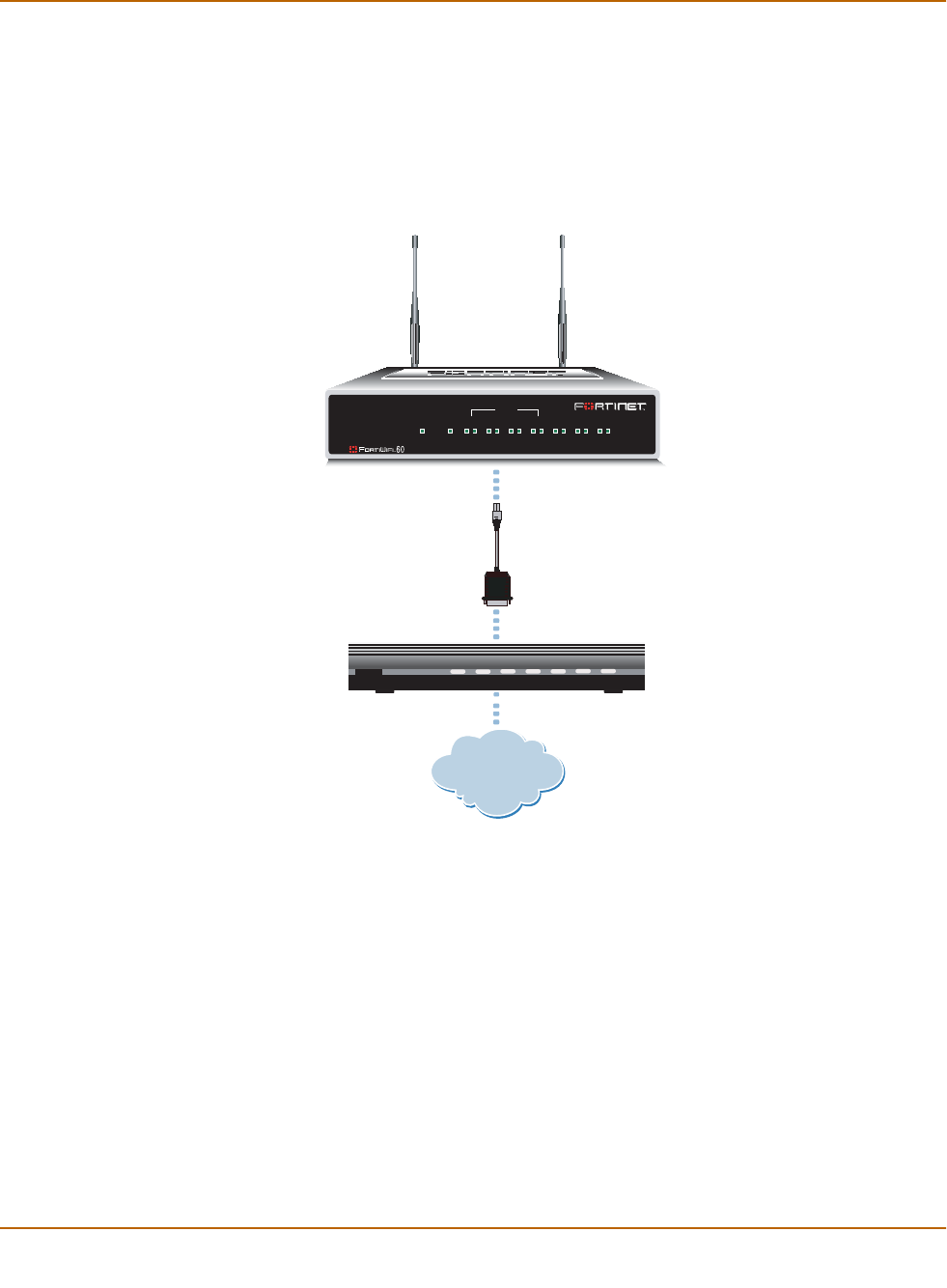
130 Fortinet Inc.
Configuring the modem interface Network configuration
Connecting a modem to the FortiWiFi unit
The FortiWiFi unit can operate with most standard external serial interface modems
that support standard Hayes AT commands. To connect, install a USB-to-serial
converter between one of the two USB ports on the FortiWiFi unit and the serial port
on the modem. The FortiWiFi unit does not support a direct USB connection between
the two devices.
Figure 10: Example modem interface network connection
Configuring modem settings
Configure modem settings so that the FortiWiFi unit uses the modem to connect to
your ISP dialup accounts. You can configure the modem to connect to up to three
dialup accounts. You can also enable and disable FortiWiFi modem support, configure
how the modem dials, and select the FortiWiFi interface that the modem is redundant
for.
To configure modem settings
1Go to System > Network > Modem.
2Select Enable USB Modem.
3Change any of the following dialup connection settings:
Internet
FortiWiFi-60
PWR
V.92
External modem
USB-to-serial
converter
USB connector
serial connector
INTERNAL
DMZ4321
LINK 100 LINK 100 LINK 100 LINK 100 LINK 100 LINK 100 LINK 100
WAN1 WA N2
PWR WLAN

Network configuration Configuring the modem interface
FortiWiFi-60 Installation and Configuration Guide 131
4Enter the following Dialup Account 1 settings:
5If you have multiple dialup accounts, enter Phone Number, User Name, and Password
for Dialup Account 2 and Dialup Account 3.
6Select Apply.
Connecting to a dialup account
Use the following procedure to connect the modem to a dialup account.
To connect to a dialup account
1Go to System > Network > Modem.
2Select Enable USB Modem.
3Make sure there is correct information in one or more Dialup Accounts.
4Select Apply if you make any configuration changes.
5Select Dial Up.
The FortiWiFi unit initiates dialing into each dialup account in turn until the modem
connects to an ISP.
Disconnecting the modem
Use the following procedure to disconnect the modem from a dialup account.
To disconnect the modem
1Go to System > Network > Modem.
2Select Hang Up if you want to disconnect from the dialup account.
Viewing modem status
To view the status of the modem connection go to System > Network > Modem.
Modem status is one of the following:
Redial Limit The maximum number of times (1-10) that the FortiWiFi unit dials the ISP to
restore an active connection on the modem interface. The default redial limit
is 1. Select None to allow the modem to never stop redialing.
Holddown
Timer For backup configurations. The time (1-60 seconds) that the FortiWiFi unit
waits before switching from the modem interface to the primary interface,
after the primary interface has been restored. The default is 1 second.
Configure a higher value if you find the FortiWiFi unit switching repeatedly
between the primary interface and the modem interface.
Redundant for To associate the modem interface with the ethernet interface that you want to
either back up (backup configuration) or replace (standalone configuration).
Phone Number The phone number required to connect to the dialup account. Do not add
spaces to the phone number. Make sure to include standard special
characters for pauses, country codes, and other functions as required by
your modem to connect to your dialup account.
User Name The user name (maximum 63 characters) sent to the ISP.
Password The password sent to the ISP.

132 Fortinet Inc.
Configuring the modem interface Network configuration
A green check mark indicates the active dialup account.
The IP address and netmask assigned to the modem interface appears on the System
Network Interface page of the web-based manager.
Backup mode configuration
The modem interface in backup mode backs up a selected ethernet interface. If that
ethernet interface disconnects from its network, the modem automatically dials the
configured dialup accounts. When the modem connects to a dialup account, the
FortiWiFi unit routes IP packets normally destined for the selected ethernet interface
to the modem interface.
The FortiWiFi unit disconnects the modem interface and switches back to the ethernet
interface when the ethernet interface can again connect to its network.
For the FortiWiFi unit to be able to switch from an ethernet interface to the modem you
must select the name of the interface in the modem configuration and configure a ping
server for that interface. You must also configure firewall policies for connections
between the modem interface and other FortiWiFi interfaces.
To configure backup mode
1Go to System > Network > Modem.
2From the Redundant for list, select the ethernet interface that you want the modem to
back up.
3Configure other modem settings as required.
See “Configuring modem settings” on page 130.
4Configure a ping server for the ethernet interface selected in step 2.
See “Adding a ping server to an interface” on page 117.
5Configure firewall policies for connections to the modem interface.
See “Adding firewall policies for modem connections” on page 133.
Standalone mode configuration
In standalone mode, you manually connect the modem to a dialup account. The
modem interface operates as the primary connection to the Internet. The FortiWiFi
unit routes traffic through the modem interface, which remains permanently connected
to the dialup account.
If the connection to the dialup account fails, the FortiWiFi unit redials the modem. The
modem redials the number of times specified by the redial limit, or until it connects to a
dialup account.
not active The modem interface is not connected to the ISP.
active The modem interface is attempting to connect to the ISP, or is connected to
the ISP.
Note: Do not add policies for connections between the modem interface and the interface that
the modem is backing up.

Network configuration Configuring the modem interface
FortiWiFi-60 Installation and Configuration Guide 133
In standalone mode the modem interface replaces the WAN1 or WAN2 ethernet
interface. When configuring the modem, you must set Redundant for to the name of
the ethernet interface that the modem interface replaces. You must also configure
firewall policies for connections between the modem interface and other FortiWiFi
interfaces.
To operate in standalone mode
1Go to System > Network > Modem.
2From the Redundant for list, select the ethernet interface that the modem is replacing.
3Configure other modem settings as required.
See “Configuring modem settings” on page 130.
Make sure there is correct information in one or more Dialup Accounts.
4Select Dial Up.
The FortiWiFi unit initiates dialing into each dialup account in turn until the modem
connects to an ISP.
5Configure firewall policies for connections to the modem interface.
See “Adding firewall policies for modem connections” on page 133.
Adding firewall policies for modem connections
The modem interface requires firewall addresses and policies. You can add one or
more addresses to the modem interface. For information about adding addresses, see
“Adding addresses” on page 169. When you add addresses, the modem interface
appears on the policy grid.
You can configure firewall policies to control the flow of packets between the modem
interface and the other interfaces on the FortiWiFi unit. For information about adding
firewall policies, see “Adding firewall policies” on page 162.
Note: Do not add a default route to the ethernet interface that the modem interface replaces.
Note: Do not add firewall policies for connections between the ethernet interface that the
modem replaces and other interfaces.

134 Fortinet Inc.
Configuring the modem interface Network configuration

FortiWiFi-60 Installation and Configuration Guide Version 2.50
FortiWiFi-60 Installation and Configuration Guide 135
RIP configuration
The FortiWiFi implementation of the Routing Information Protocol (RIP) supports both
RIP version 1 as defined by RFC 1058, and RIP version 2 as defined by RFC 2453.
RIP version 2 enables RIP messages to carry more information, and to support simple
authentication and subnet masks.
RIP is a distance-vector routing protocol intended for small, relatively homogeneous,
networks. RIP uses hop count as its routing metric. Each network is usually counted
as one hop. The network diameter is limited to 15 hops.
This chapter describes how to configure FortiWiFi RIP:
•RIP settings
•Configuring RIP for FortiWiFi interfaces
•Adding RIP filters
RIP settings
To configure RIP on the FortiWiFi unit
1Go to System > RIP > Settings.
2Select Enable RIP.
When you enable RIP, the FortiWiFi unit starts the RIP process. The FortiWiFi unit
does not send or receive RIP packets until you enable RIP on at least one interface.
For information about configuring RIP, see “Configuring RIP for FortiWiFi interfaces”
on page 137.
3Select Enable Advertise Default if you want RIP to always send the default route to
neighbors whether or not the default route is in the static routing table.
If you disable Advertise Default, RIP never sends the default route.
4Change the following RIP default settings, as required.
RIP defaults are effective in most configurations. You should only have to change
these settings to troubleshoot problems with the RIP configuration.

136 Fortinet Inc.
RIP settings RIP configuration
5Change the following RIP timer settings, as required.
RIP timer defaults are effective in most configurations. You should only have to
change these timers to troubleshoot network routing problems. All routers and access
servers in the network should have the same RIP timer settings.
6Select Apply to save the changes.
Default Metric RIP uses the default metric to advertise routes learned from other routing
protocols. Set Default Metric to a positive integer lower than 16 to advertise
that metric for all routes learned from other routing protocols. The default
setting for the Default Metric is 2.
Input Queue Change the depth of the RIP input queue. The higher the number, the deeper
the input queue. Change the input queue depth to prevent loss of information
from the routing table when you have a FortiWiFi unit sending at high speed
to a router that cannot receive at high speed. The range is 0 to 1024. The
default input queue depth is 50. A queue size of 0 means there is no input
queue.
Output Delay Add a delay in milliseconds between packets in a multiple-packet RIP
update. Add an output delay if you are configuring RIP on a FortiWiFi unit
that could be sending packets to a router that cannot receive the packets at
the rate the FortiWiFi unit is sending them. Output Delay can be from 8 to 50
milliseconds. The default output delay is 0 milliseconds.
Update The time interval in seconds between RIP updates. The default is 30
seconds.
Invalid The time interval in seconds after which a route is declared invalid. Invalid
should be at least three times the value of Update.
During the invalid interval, after the first update is missed and before the
invalid timer expires, the route is marked inaccessible and advertised as
unreachable; however, the route is still used for forwarding packets. The
invalid interval allows for the loss of one or more update packets before RIP
considers the route unusable. If RIP receives an update for a route, before
the invalid timer expires, it resets the invalid timer to 0. The default for Invalid
is 180 seconds.
Holddown The time interval in seconds during which RIP ignores routing information for
a route. Holddown should be at least three times the value Update.
A route enters the holddown state when RIP receives an update packet
indicating that a route is unreachable or when the invalid timer for the route
expires. The holddown interval allows time for bad routing information to
clear the network during network convergence. The route is marked
inaccessible and advertised as unreachable and is no longer used for
forwarding packets. The default for Holddown is 180 seconds.
Flush The time in seconds that must elapse after the last update for a route before
RIP removes the route from the routing table. Flush should be greater than
the value of Invalid to allow the route to go into the holddown state. The
default for Flush is 240 seconds.
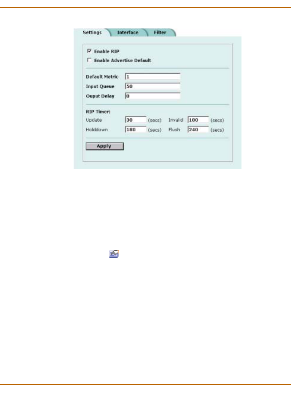
RIP configuration Configuring RIP for FortiWiFi interfaces
FortiWiFi-60 Installation and Configuration Guide 137
Figure 1: Configuring RIP settings
Configuring RIP for FortiWiFi interfaces
You can customize a RIP configuration for each FortiWiFi interface. This allows you to
customize RIP for the network to which each interface is connected.
To configure RIP for FortiWiFi interfaces
1Go to System > RIP > Interface.
On this page you can view a summary of the RIP settings for each FortiWiFi interface.
2Select Modify for the interface for which to configure RIP settings.
3Configure any of the following RIP settings:
RIP1 Send Enables sending RIP version 1 broadcasts from this interface to the network
it is connected to. The routing broadcasts are UDP packets with a destination
port of 520.
RIP1 Receive Enables listening on port 520 of an interface for RIP version 1 broadcasts.
RIP2 Send Enables sending RIP version 2 broadcasts from this interface to the network
it is connected to. The routing broadcasts are UDP packets with a destination
port of 520.
RIP2 Receive Enables listening on port 520 of an interface for RIP version 2 broadcasts.
Split-Horizon Prevents RIP from sending updates for a route back out the interface from
which it received those routes. Split horizon is enabled by default. You should
only disable split horizon if there is no possibility of creating a counting to
infinity loop when network topology changes.
Authentication Enables authentication for RIP version 2 packets sent and received by an
interface. Because the original RIP standard does not support authentication,
authentication is only available for RIP version 2.
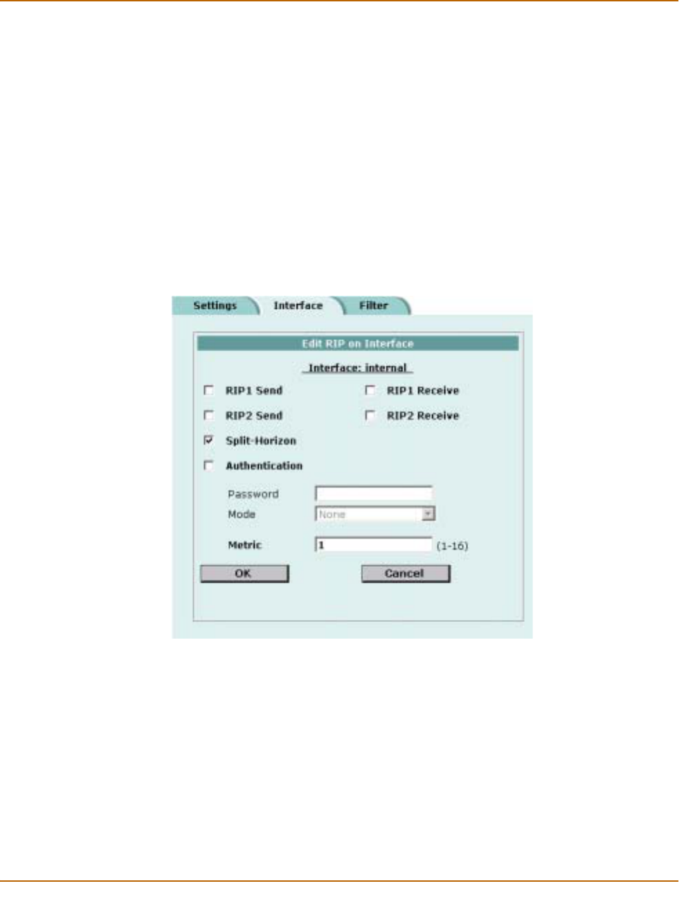
138 Fortinet Inc.
Configuring RIP for FortiWiFi interfaces RIP configuration
4Select OK to save the RIP configuration for the selected interface.
Figure 2: Example RIP configuration for an internal interface
Password Enter the password to be used for RIP version 2 authentication. The
password can be up to 16 characters long.
Mode Defines the authentication used for RIP version 2 packets sent and received
by this interface. If you select Clear, the password is sent as plain text. If you
select MD5, the password is used to generate an MD5 hash.
MD5 only guarantees the authenticity of the update packet, not the
confidentiality of the routing information in the packet.
Metric Changes the metric for routes sent by this interface. All routes sent from this
interface have this metric added to their current metric value. You can
change the interface metric to give a higher priority to an interface. For
example, if you have two interfaces that can be used to route packets to the
same destination, and you set the metric of one interface higher than the
other, the routes to the interface with the lower metric will seem to have a
lower cost. More traffic will use routes to the interface with the lower metric.
Metric can be from 1 to 16 with 16 equalling unreachable.

RIP configuration Adding RIP filters
FortiWiFi-60 Installation and Configuration Guide 139
Adding RIP filters
Use the Filter page to create RIP filter lists and assign RIP filter lists to the neighbors
filter, incoming route filter, or outgoing route filter. The neighbors filter allows or denies
updates from other routers. The incoming filter accepts or rejects routes in an
incoming RIP update packet. The outgoing filter allows or denies adding routes to
outgoing RIP update packets.
Each entry in a RIP filter list consists of a prefix (IP address and netmask), the action
RIP should take for this prefix (allow or deny), and the interface to which to apply this
RIP filter list entry. When RIP applies a filter while processing an update packet, it
starts at the top of the filter list and works down through the list looking for a matching
prefix. If RIP finds a matching prefix, it then checks that the interface in the filter list
entry matches the interface that the packet is received or sent on. If both prefix and
interface match, RIP takes the action specified. If no match is found, the default action
is allow.
• For the neighbors filter, RIP attempts to match prefixes in the filter list against the
source address in the update packet.
• For the incoming filter, RIP attempts to match prefixes in the filter list against
prefixes in the routing table entries in the update packet.
• For the outgoing filter, RIP attempts to match prefixes in the filter list against
prefixes in the RIP routing table.
You can add up to four RIP filter lists to the FortiWiFi RIP configuration. You can then
select one RIP filter list for each RIP filter type: neighbors, incoming routes, outgoing
routes. If you do not select a RIP filter list for any of the RIP filter types, no filtering is
applied.
This section describes:
•Adding a RIP filter list
•Assigning a RIP filter list to the neighbors filter
•Assigning a RIP filter list to the incoming filter
•Assigning a RIP filter list to the outgoing filter
Adding a RIP filter list
Each entry in a RIP filter list consists of a prefix (IP address and netmask), the action
RIP should take for this prefix (allow or deny), and the interface to which to apply this
RIP filter list entry.
To add a RIP filter list
1Go to System > RIP > Filter.
2Select New to add a RIP filter.
Note: To block all updates not specifically allowed in a filter list, create an entry at the bottom of
the filter list with a prefix with 0.0.0.0 for the IP address, 0.0.0.0 for the netmask, and action set
to deny. Because RIP uses the first match it finds in a top down search of the filter list, all the
allowed entries are matched first, and all other entries for the specified interface are matched by
the last entry and denied. Create a separate entry at the bottom of the filter list for each
interface for which you want to deny all updates not specifically allowed.

140 Fortinet Inc.
Adding RIP filters RIP configuration
3For Filter Name, type a name for the RIP filter list.
The name can be 15 characters long and can contain upper and lower case letters,
numbers, and special characters. The name cannot contain spaces.
4Select the Blank Filter check box to create a RIP filter list with no entries, or enter the
information for the first entry on the RIP filter list.
5Enter the IP address and Mask to create the prefix.
6For Action, select allow or deny.
7For Interface, enter the name of the interface to which to apply the entry.
8Select OK to save the RIP filter list.
To add an entry to a RIP filter list
1Go to System > RIP > Filter.
2For the RIP filter list name, select Add Prefix to add an entry to the filter list.
3Enter the IP address and Mask to create the prefix.
4For Action, select allow or deny.
5For Interface, enter the name of the interface to which to apply the entry.
6Select OK to add the entry to the RIP filter list.
7Repeat steps 2 to 6 to add entries to the RIP filter list.
Assigning a RIP filter list to the neighbors filter
The neighbors filter allows or denies updates from other routers. You can assign a
single RIP filter list to the neighbors filter.
To assign a RIP filter list to the neighbors filter
1Go to System > RIP > Filter.
2Add RIP filter lists as required.
3For Neighbors Filter, select the name of the RIP filter list to assign to the neighbors
filter.
4Select Apply.
Assigning a RIP filter list to the incoming filter
The incoming filter accepts or rejects routes in an incoming RIP update packet. You
can assign a single RIP filter list to the incoming filter.
To assign a RIP filter list to the incoming filter
1Go to System > RIP > Filter.
2Add RIP filter lists as required.
3For Incoming Routes Filter, select the name of the RIP filter list to assign to the
incoming filter.
4Select Apply.