Fortress Technologies ES210 The ES210 is a single radio access point/bridge User Manual HW Guide
Fortress Technologies, Inc. The ES210 is a single radio access point/bridge HW Guide
UserManual.wiki
>
Fortress Technologies
>
ES210 User Manual
>
HW Guide
Contents
1.
Manual
2.
GUI Guide
3.
HW Guide
4.
User Manual
HW Guide
Navigation menu
Upload a User Manual
Namespaces
Wiki Guide
HTML
PDF
Info
Views
User Manual
Discussion / Help
Navigation
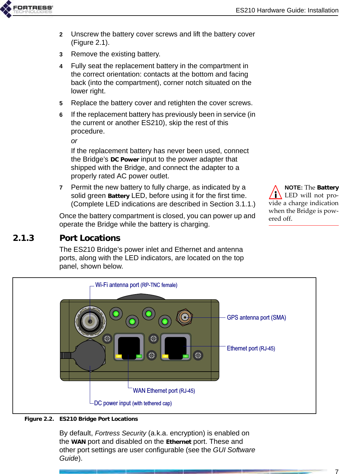
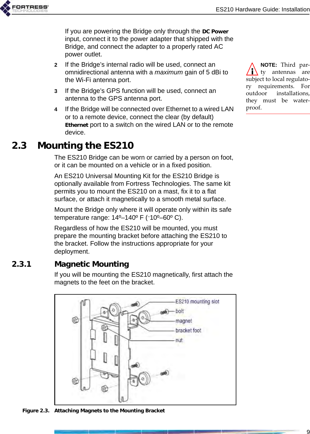
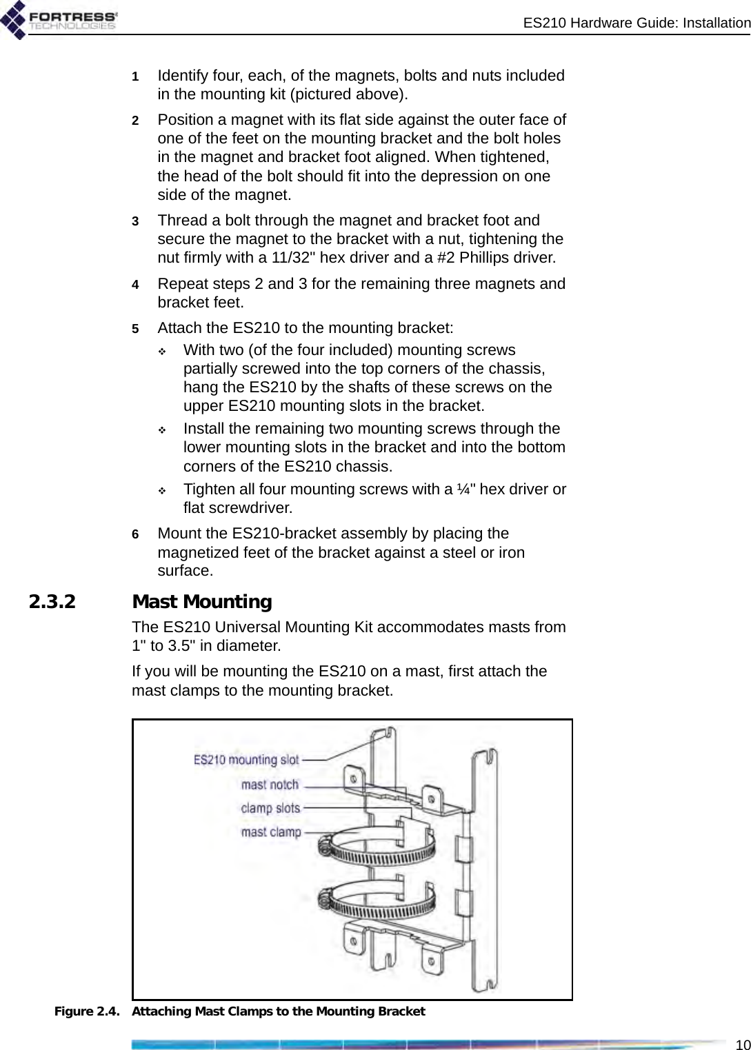
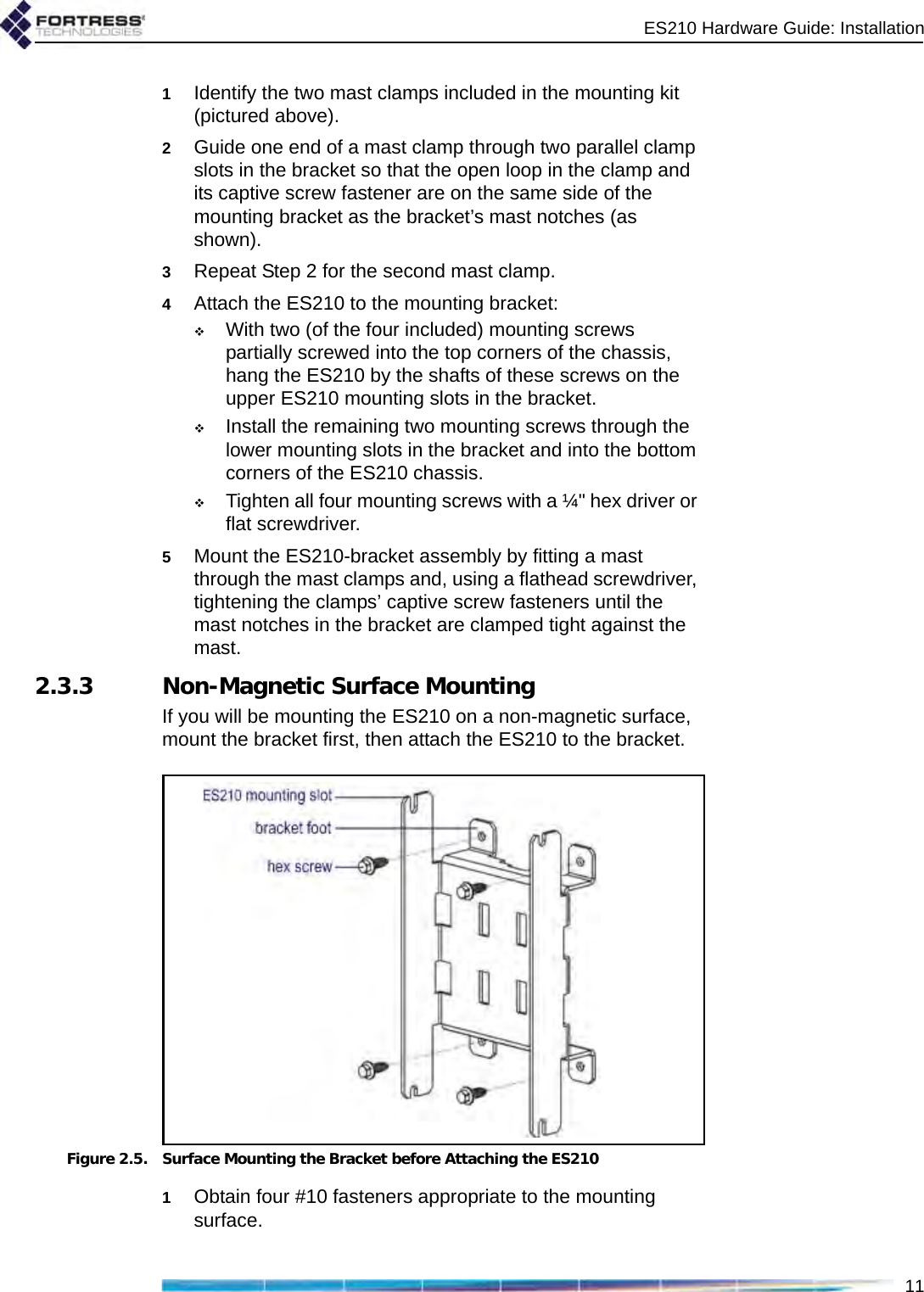
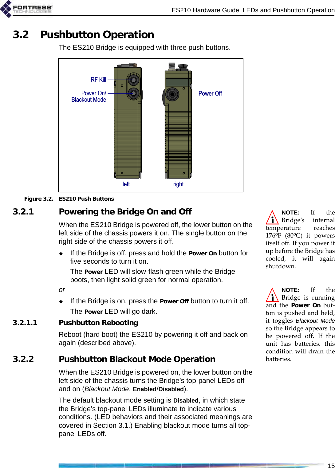
![ES210 Hardware Guidei009-00027-00r1Fortress ES210 Secure Wireless Bridge [rev.1]Copyright © 2010 Fortress Technologies, Inc. All rights reserved.This document contains proprietary information protected by copyright. No part of this document may be reproduced or transmitted in any form or by any means, electronic or mechanical, without written permission of Fortress Technologies, 4023 Tampa Road, Suite 2000, Oldsmar, FL 34677, except as specified in the Product Warranty and License Terms.FORTRESS TECHNOLOGIES, INC., MAKES NO WARRANTY OF ANY KIND WITH REGARD TO THIS MATERIAL, INCLUDING BUT NOT LIMITED TO THE IMPLIED WARRANTIES OF MERCHANTABILITY AND FITNESS FOR A PARTICULAR PURPOSE. FORTRESS TECHNOLOGIES, INC. SHALL NOT BE LIABLE FOR ERRORS CONTAINED HEREIN OR FOR INCIDENTAL OR CONSEQUENTIAL DAMAGES IN CONNECTION WITH THE FURNISHING, PERFORMANCE OR USE OF THIS MATERIAL. THE INFORMATION IN THIS DOCUMENT IS SUBJECT TO CHANGE WITHOUT NOTICE.The Fortress Technologies and AirFortress logos and AirFortress and are registered trademarks; Multi-Factor Authentication, Unified Security Model, Wireless Link Layer Security and Three Factor Authentication (TFA) are trademarks of Fortress Technologies, Inc. The technology behind Wireless Link Layer Security™ enjoys U.S. and international patent protection under patent number 5,757,924.All other trademarks mentioned in this document are the property of their respective owners.FCC EMISSIONS COMPLIANCE STATEMENTTHIS EQUIPMENT HAS BEEN TESTED AND FOUND TO COMPLY WITH THE LIMITS FOR A CLASS B DIGITAL DEVICE, PURSUANT TO PART 15 OF THE FCC RULES. THESE LIMITS ARE DESIGNED TO PROVIDE REASONABLE PROTECTION AGAINST HARMFUL INTERFERENCE IN A RESIDENTIAL INSTALLATION. THIS EQUIPMENT GENERATES, USES, AND CAN RADIATE RADIO FREQUENCY ENERGY AND, IF NOT INSTALLED AND USED IN ACCORDANCE WITH THE INSTRUCTIONS, MAY CAUSE HARMFUL INTERFERENCE TO RADIO COMMUNICATIONS. HOWEVER, THERE IS NO GUARANTEE THAT INTERFERENCE WILL NOT OCCUR IN A PARTICULAR INSTALLATION. IF THIS EQUIPMENT DOES CAUSE HARMFUL INTERFERENCE TO RADIO OR TELEVISION RECEPTION, WHICH CAN BE DETERMINED BY TURNING THE EQUIPMENT OFF AND ON, THE USER IS ENCOURAGED TO TRY TO CORRECT THE INTERFERENCE BY ONE OR MORE OF THE FOLLOWING MEASURES:• REORIENT OR RELOCATE THE RECEIVING ANTENNA.• INCREASE THE SEPARATION BETWEEN THE EQUIPMENT AND THE RECEIVER.• CONNECT THE EQUIPMENT INTO AN OUTLET ON A CIRCUIT DIFFERENT FROM THAT TO WHICH THE REC I EVER IS CONNECTED.• CONSULT THE DEALER OR AN EXPERIENCED RADIO/TV TECHNICIAN FOR HELP.](https://usermanual.wiki/Fortress-Technologies/ES210.HW-Guide/User-Guide-1413934-Page-2.png)