Fortress Technologies ES210 The ES210 is a single radio access point/bridge User Manual ES210 Tactical Mesh Point Hardware Guide rev 2
Fortress Technologies, Inc. The ES210 is a single radio access point/bridge ES210 Tactical Mesh Point Hardware Guide rev 2
Contents
- 1. Manual
- 2. GUI Guide
- 3. HW Guide
- 4. User Manual
User Manual

Fortress Security System
ES210
Tactical Mesh Point
Hardware Guide
www.fortresstech.com
© 2011 Fortress Technologies

ES210 Hardware Guide
i
009-00027-00r2
Fortress ES210 Tactical Mesh Point [rev.2]
Copyright © 2011 Fortress Technologies, Inc. All rights reserved.
This document contains proprietary information protected by copyright. No part of this
document may be reproduced or transmitted in any form or by any means, electronic or
mechanical, without written permission of Fortress Technologies, 1 Technology Park Drive,
Westford, MA 01886-3140, except as specified in the Product Warranty and License
Terms.
FORTRESS TECHNOLOGIES, INC., MAKES NO WARRANTY OF ANY KIND WITH
REGARD TO THIS MATERIAL, INCLUDING BUT NOT LIMITED TO THE IMPLIED
WARRANTIES OF MERCHANTABILITY AND FITNESS FOR A PARTICULAR PURPOSE.
FORTRESS TECHNOLOGIES, INC. SHALL NOT BE LIABLE FOR ERRORS
CONTAINED HEREIN OR FOR INCIDENTAL OR CONSEQUENTIAL DAMAGES IN
CONNECTION WITH THE FURNISHING, PERFORMANCE OR USE OF THIS
MATERIAL. THE INFORMATION IN THIS DOCUMENT IS SUBJECT TO CHANGE
WITHOUT NOTICE.
The Fortress Technologies and AirFortress logos and AirFortress and are registered
trademarks; Multi-Factor Authentication, Unified Security Model, Wireless Link Layer
Security and Three Factor Authentication (TFA) are trademarks of Fortress Technologies,
Inc. The technology behind Wireless Link Layer Security™ enjoys U.S. and international
patent protection under patent number 5,757,924.
All other trademarks mentioned in this document are the property of their respective
owners.
IMPORTANT FCC INFORMATION
The Federal Communications Commission has released Office of Engineering and Technology
Laboratory Division Knowledge Database (KDB) 44399, which refines the definition of Dynamic
Frequency Selection (DFS) support. Since this device has the ability to use frequencies covered
by DFS, KDB 443999 must be followed. It is published in full on the FCC web site:
https://apps.fcc.gov/oetcf/kdb/forms/FTSSearchResultPage.cfm?switch=P&id=41732
In order to support FCC KDB 443999, Fortress has limited the use of certain frequencies within
the 5400–5725 MHz range. Specifically, the frequencies defined by the FCC as being of primary
interest are those in the 5600–5650 MHz range, which correspond to 802.11a channels 120, 124,
and 128. In order to comply with the KDB 443999, these channels have been removed from use,
or notched. Notched channels are unavailable for use on this device.
KDB 44399 provides additional restrictions on the use of channels within 30 MHz of notched
channels when the device is within 35 km of a Terminal Doppler Weather Radar (TDWR)
installation. Affected channels 116, 132, and 136 serve as a guard of 30 MHz around the critical
notched frequencies. Guard frequencies are unavailable for use on this device by default. The
FCC allows these channels to be used, however, as long as the device is not within 35 km of a
TDWR installation, as described in this excerpt of KDB 443999:
Any installation of either a master or a client device within 35 km of a TDWR location shall
be separated by at least 30 MHz (center-to-center) from the TDWR operating frequency.
In some instances it is possible that a device may be within 35 km of multiple TDWRs. In
this case the device must ensure that it avoids operation within 30 MHz for each of the
TDWRs. This requirement applies even if the master is outside the 35 km radius but
communicates with outdoor clients which may be within the 35 km radius of the TDWRs.
The requirement for ensuring 30 MHz frequency separation is based on the best
information available to date. If interference is not eliminated, a distance limitation based
on line-of-sight from TDWR will need to be used.
Please refer to the original KDB 443999 as posted on the FCC web site for the complete text.

ES210 Hardware Guide
ii
In order to enable channels 116, 132, and/or 136, please contact Fortress to obtain a special
license. This license will be issued after it is confirmed that the installation is not within 30 MHz and
35 km of registered TDWR sites. The following table (provided by the FCC in KDB 443999
published on 10/14/2010) describes the locations of TDWR sites, as well as the frequencies at
which these sites operate:
TDWR Location Information TERRAIN
ELEVATION
(MSL) [ft]
ANTENNA
HEIGHT ABOVE
TERRAIN [ft]
STATE CITY LONGITUDE LATITUDE FREQUENCY
AZ PHOENIX W 112 09 46 N 33 25 14 5610 MHz 1024 64
CO DENVER W 104 31 35 N 39 43 39 5615 MHz 5643 64
FL FT LAUDERDALE W 080 20 39 N 26 08 36 5645 MHz 7 113
FL MIAMI W 080 29 28 N 25 45 27 5605 MHz 10 113
FL ORLANDO W 081 19 33 N 28 20 37 5640 MHz 72 97
FL TAMPA W 082 31 04 N 27 51 35 5620 MHz 14 80
FL WEST PALM BEACH W 080 16 23 N 26 41 17 5615 MHz 20 113
GA ATLANTA W 084 15 44 N 33 38 48 5615 MHz 962 113
IL MCCOOK W 087 51 31 N 41 47 50 5615 MHz 646 97
IL CRESTWOOD W 087 43 47 N 41 39 05 5645 MHz 663 113
IN INDIANAPOLIS W 086 26 08 N 39 38 14 5605 MHz 751 97
KS WICHITA W 097 26 13 N 37 30 26 5603 MHz 1270 80
KY COVINGTON
CINCINNATI W 084 34 48 N 38 53 53 5610 MHz 942 97
KY LOUISVILLE W 085 36 38 N 38 02 45 5646 MHz 617 113
LA NEW ORLEANS W 090 24 11 N 30 01 18 5645 MHz 2 97
MA BOSTON W 070 56 01 N 42 09 30 5610 MHz 151 113
MD BRANDYWINE W 076 50 42 N 38 41 43 5635 MHz 233 113
MD BENFIELD W 076 37 48 N 39 05 23 5645 MHz 184 113
MD CLINTON W 076 57 43 N 38 45 32 5615 MHz 249 97
MI DETROIT W 083 30 54 N 42 06 40 5615 MHz 656 113
MN MINNEAPOLIS W 092 55 58 N 44 52 17 5610 MHz 1040 80
MO KANSAS CITY W 094 44 31 N 39 29 55 5605 MHz 1040 64
MO SAINT LOUIS W 090 29 21 N 38 48 20 5610 MHz 551 97
MS DESOTO COUNTY W 089 59 33 N 34 53 45 5610 MHz 371 113
NC CHARLOTTE W 080 53 06 N 35 20 14 5608 MHz 757 113
NC RALEIGH DURHAM W 078 41 50 N 36 00 07 5647 MHz 400 113
NJ WOODBRIDGE W 074 16 13 N 40 35 37 5620 MHz 19 113
NJ PENNSAUKEN W 075 04 12 N 39 56 57 5610 MHz 39 113
NV LAS VEGAS W 115 00 26 N 36 08 37 5645 MHz 1995 64
NY FLOYD BENNETT
FIELD W 073 52 49 N 40 35 20 5647 MHz 8 97
OH DAYTON W 084 07 23 N 40 01 19 5640 MHz 922 97
OH CLEVELAND W 082 00 28 N 41 17 23 5645 MHz 817 113
OH COLUMBUS W 082 42 55 N 40 00 20 5605 MHz 1037 113
OK AERO. CTR TDWR #1 W 097 37 31 N 35 24 19 5610 MHz 1285 80
OK AERO. CTR TDWR #2 W 097 37 43 N 35 23 34 5620 MHz 1293 97
OK TULSA W 095 49 34 N 36 04 14 5605 MHz 712 113
OK OKLAHOMA CITY W 097 30 36 N 35 16 34 5603 MHz 1195 64
PA HANOVER W 080 29 10 N 40 30 05 5615 MHz 1266 113
PR SAN JUAN W 066 10 46 N 18 28 26 5610 MHz 59 113
TN NASHVILLE W 086 39 42 N 35 58 47 5605 MHz 722 97
TX HOUSTON
INTERCONTL W 095 34 01 N 30 03 54 5605 MHz 154 97

ES210 Hardware Guide
iii
In addition, the FCC recommends that all operators and installers register with the WISPA
database used by government agencies to quickly find devices that may be causing interference
and notify their owners/operators to shut them down. This registration is not required, but Fortress
strongly recommends that all systems be registered, as described in this excerpt of KDB 44399:
A voluntary WISPA sponsored database has been developed that allows operators
and installers to register the location information of the UNII devices operating
outdoors in the 5470 – 5725 MHz band within 35 km of any TDWR location (see
http://www.spectrumbridge.com/udia/home.aspx). This database may be used by
government agencies in order to expedite resolution of any interference to TDWRs.
KDB 443999 further specifies that the requirements of KDB 594280 must also be met.
KDB 594280 is published in full on the FCC web site:
https://apps.fcc.gov/oetcf/kdb/forms/FTSSearchResultPage.cfm?switch=P&id=39498.
This device meets KDB 594280 by not allowing any configuration options to be made such that the
device could be taken out of compliance. There is no ability for the user to change country codes
or to select power levels that would take the device out of compliance.
For customers such as the U.S. military or others willing to produce evidence that particular
devices will be used only outside of the United States, a special license can be obtained from
Fortress that will allow those devices the option of selecting a different, non-U.S. country code.
Fortress creates such licenses only for those customers who offer proof of non-U.S. device usage,
and licenses are specific to particular devices and are not transferrable. Devices having such a
license should NOT be considered to be compliant with FCC regulatory requirements. Please
contact Fortress with questions about these special licences.
Only software that has been signed by Fortress using the Fortress private key can be loaded onto
a Fortress device, thus insuring that no software other than that which is controlled and signed by
Fortress can by loaded onto the device.
FCC EMISSIONS COMPLIANCE STATEMENT
THIS EQUIPMENT HAS BEEN TESTED AND FOUND TO COMPLY
WITH THE LIMITS FOR A CLASS B DIGITAL DEVICE, PURSUANT TO
PART 15 OF THE FCC RULES. THESE LIMITS ARE DESIGNED TO
PROVIDE REASONABLE PROTECTION AGAINST HARMFUL
INTERFERENCE IN A RESIDENTIAL INSTALLATION. THIS
EQUIPMENT GENERATES, USES, AND CAN RADIATE RADIO
FREQUENCY ENERGY AND, IF NOT INSTALLED AND USED IN
ACCORDANCE WITH THE INSTRUCTIONS, MAY CAUSE HARMFUL
INTERFERENCE TO RADIO COMMUNICATIONS. HOWEVER, THERE
IS NO GUARANTEE THAT INTERFERENCE WILL NOT OCCUR IN A
PARTICULAR INSTALLATION. IF THIS EQUIPMENT DOES CAUSE
HARMFUL INTERFERENCE TO RADIO OR TELEVISION RECEPTION,
WHICH CAN BE DETERMINED BY TURNING THE EQUIPMENT OFF
AND ON, THE USER IS ENCOURAGED TO TRY TO CORRECT THE
INTERFERENCE BY ONE OR MORE OF THE FOLLOWING
MEASURES:
• REORIENT OR RELOCATE THE RECEIVING ANTENNA.
• INCREASE THE SEPARATION BETWEEN THE EQUIPMENT AND
THE RECEIVER.
• CONNECT THE EQUIPMENT INTO AN OUTLET ON A CIRCUIT
DIFFERENT FROM THAT TO WHICH THE REC I EVER IS
CONNECTED.

ES210 Hardware Guide
iv
• CONSULT THE DEALER OR AN EXPERIENCED RADIO/TV
TECHNICIAN FOR HELP.
YOU MAY ALSO FIND HELPFUL THE FOLLOWING BOOKLET,
PREPARED BY THE FCC: “HOW TO IDENTIFY AND RESOLVE RADIO-
TV INTERFERENCE PROBLEMS.” THIS BOOKLET IS AVAILABLE
FROM THE U.S. GOVERNMENT PRINTING OFFICE, WASHINGTON,
D.C. 20402
CHANGES AND MODIFICATIONS NOT EXPRESSLY APPROVED BY
THE MANUFACTURER OR REGISTRANT OF THIS EQUIPMENT CAN
VOID YOUR AUTHORITY TO OPERATE THIS EQUIPMENT UNDER
FEDERAL COMMUNICATIONS COMMISSION RULES.
IN ORDER TO MAINTAIN COMPLIANCE WITH FCC REGULATIONS,
SHIELDED CABLES MUST BE USED WITH THIS EQUIPMENT.
OPERATION WITH NON-APPROVED EQUIPMENT OR UNSHIELDED
CABLES IS LIKELY TO RESULT IN INTERFERENCE TO RADIO AND
TELEVISION RECEPTION.
ANTENNA RESTRICTIONS
THIS DEVICE HAS BEEN DESIGNED TO OPERATE WITH ANTENNAS
THAT HAVE A MAXIMUM GAIN OF 5 dBi. ANTENNAS HAVING A GAIN
GREATER THAN 5 dBi ARE STRICTLY PROHIBITED FOR USE WITH
THIS DEVICE. THE REQUIRED ANTENNA IMPEDANCE IS 50 OHMS.

ES210 Hardware Guide: Table of Contents
v
Table of Contents
1
Overview 1
This Document . . . . . . . . . . . . . . . . . . . . . . . . . . . . . . . . . . . . . . . . .1
Related Documents . . . . . . . . . . . . . . . . . . . . . . . . . . . . . . . . . . . . . . . . . . .1
The ES210 . . . . . . . . . . . . . . . . . . . . . . . . . . . . . . . . . . . . . . . . . . . .2
Shipped and Optional Parts . . . . . . . . . . . . . . . . . . . . . . . . . . . . . . . . . . . . .2
2
Installation 3
Preparation . . . . . . . . . . . . . . . . . . . . . . . . . . . . . . . . . . . . . . . . . . . .3
Safety Requirements . . . . . . . . . . . . . . . . . . . . . . . . . . . . . . . . . . . . . . . . . .3
Battery Use and Maintenance . . . . . . . . . . . . . . . . . . . . . . . . . . . . . . . . . . .5
Port Locations . . . . . . . . . . . . . . . . . . . . . . . . . . . . . . . . . . . . . . . . . . . . . . . .7
Connecting the ES210 . . . . . . . . . . . . . . . . . . . . . . . . . . . . . . . . . . .8
Connections for Preconfiguration . . . . . . . . . . . . . . . . . . . . . . . . . . . . . . . . . 8
Connections for Deployment . . . . . . . . . . . . . . . . . . . . . . . . . . . . . . . . . . . .9
Mounting the ES210 . . . . . . . . . . . . . . . . . . . . . . . . . . . . . . . . . . . . .9
Magnetic Mounting . . . . . . . . . . . . . . . . . . . . . . . . . . . . . . . . . . . . . . . . . . . 10
Mast Mounting . . . . . . . . . . . . . . . . . . . . . . . . . . . . . . . . . . . . . . . . . . . . . . 11
Non-Magnetic Surface Mounting . . . . . . . . . . . . . . . . . . . . . . . . . . . . . . . . 12

ES210 Hardware Guide: Table of Contents
vi
3
LEDs and Pushbutton Operation 13
Top-Panel Indicators . . . . . . . . . . . . . . . . . . . . . . . . . . . . . . . . . . . . 13
System LEDs . . . . . . . . . . . . . . . . . . . . . . . . . . . . . . . . . . . . . . . . . . . . . . . 13
Port LEDs . . . . . . . . . . . . . . . . . . . . . . . . . . . . . . . . . . . . . . . . . . . . . . . . . . 14
Pushbutton Operation . . . . . . . . . . . . . . . . . . . . . . . . . . . . . . . . . . . 15
Powering the Mesh Point On and Off . . . . . . . . . . . . . . . . . . . . . . . . . . . . . 15
Pushbutton Blackout Mode Operation . . . . . . . . . . . . . . . . . . . . . . . . . . . . 15
Pushbutton RF Kill Operation . . . . . . . . . . . . . . . . . . . . . . . . . . . . . . . . . . . 16
Pushbutton Restoring Defaults . . . . . . . . . . . . . . . . . . . . . . . . . . . . . . . . . . 16
4
Specifications 17
Hardware Specifications . . . . . . . . . . . . . . . . . . . . . . . . . . . . . . . . . 17
Physical Specifications . . . . . . . . . . . . . . . . . . . . . . . . . . . . . . . . . . . . . . . . 17
Battery Specifications . . . . . . . . . . . . . . . . . . . . . . . . . . . . . . . . . . . . . . . . . 18
Environmental Specifications . . . . . . . . . . . . . . . . . . . . . . . . . . . . . . . . . . . 18
Compliance and Standards . . . . . . . . . . . . . . . . . . . . . . . . . . . . . . . . . . . . 18
DB9-to-3-pin Console Port Adapter . . . . . . . . . . . . . . . . . . . . . . . . 19
2-Pin DC Input Connector . . . . . . . . . . . . . . . . . . . . . . . . . . . . . . . . 19
ES210 Hardware Guide: Overview
1
Chapter 1
Overview
1.1 This Document
WARNING: can
cause physical in-
jury or death and/or se-
verely damage your
equipment.
This user guide covers preparing and installing the ES210
Fortress Mesh Point hardware. It also describes the LED
indicators and push button operation, and provides
specifications. Other Fortress hardware devices are covered in
separate hardware guides, one for each Mesh Point (or
Network Encryptor) model.
Fortress Mesh Point user guidance is intended for professional
system and network administrators and assumes that its users
have a level of technical expertise consistent with these roles.
CAUTION: can cor-
rupt your net-
work, your data or an
intended result.
Side notes throughout this document are intended to alert you
to particular kinds of information, as visually indicated by their
icons. Examples appear to the right of this section, in
descending order of urgency.
NOTE: may assist
you in executing
the task, e.g. a conve-
nient software feature or
notice of something to
keep in mind.
1.1.1 Related Documents
Each Fortress hardware series runs the same Fortress
software, and differences between ES and FC series software
are minor. Fortress software user guidance covers all current
Fortress hardware platforms.
Fortress Mesh Point software guides include:
Mesh Point and Network Encryptor Software GUI Guide
Mesh Point and Network Encryptor Software CLI Guide
Mesh Point and Network Encryptor Software Auto Config
Guide
In addition to this guide, the Fortress hardware guides include:
ES440 Infrastructure Mesh Point Hardware Guide
ES520 Deployable Mesh Point Hardware Guide
ES820 Vehicle Mesh Point Hardware Guide
FC-X Inline Network Encryptor Hardware Guide

ES210 Hardware Guide: Overview
2
1.2 The ES210
The Fortress ES210 Tactical Mesh Point is a full-featured
Fortress network device, providing strong data encryption and
Multi-factor Authentication™, including native RADIUS
(Remote Authentication Dial-In User Service) authentication, to
users and devices on the network it secures.
The ES210 Mesh Point is equipped with a dual-band
802.11a/b/g/n radio that can be configured to use either the
802.11b/g band or the 802.11a band, with an option for 802.11n
capability in either band. It can function simultaneously as a
wireless access point (AP), providing secure connectivity to
wireless devices within range, and as a wireless bridge or a
node in a mesh network.
1.2.1 Shipped and Optional Parts
Each shipment includes:
one ES210 Tactical Mesh Point
one 7.4V lithium ion polymer battery
one standard AC/DC power supply (part # 16282-2SG-315)
protective caps for all connector ports
software CD, including:
ES210 Mesh Point software package
Fortress and standard SNMP MIBs
RADIUS dictionary file with Fortress Vendor-Specific
Attributes for administrative authentication
ES210 Mesh Point user guides and release notes
Optionally, you can purchase a universal Mounting Kit for the
ES210 (part # 381-00005-01).

ES210 Hardware Guide: Installation
3
Chapter 2
Installation
2.1 Preparation
Before using or charging an ES210 battery, review the initial
installation and charging information in Section 1.1.
Before proceeding with installation, review the safety
information in Section 2.1.1 below.
WARNING:
To
avoid the risk of
severe electrical shock,
never remove part of the
ES210’s chassis
other
than the battery cover
and serial port cap, as
directed in this guide.
There are no user-ser-
viceable parts inside. Re-
fer all hardware
servicing to Fortress
Technical Support.
2.1.1 Safety Requirements
To prevent damage to the product and ensure your personal
safety, operate the ES210 Tactical Mesh Point only within the
operating specifications given in Section 4.1.3, and carefully
follow these guidelines:
General: This equipment must be installed by qualified
service personnel according to the applicable installation
codes. Do not locate the Mesh Point or antennas near
power lines or power circuits.
Transportation: The carton is marked with a Lithium-Ion
label, per Department of Transportation (DOT)
requirements. The unit is shipped with batteries installed in
the device.
Indoor/Outdoor Siting: All interconnected equipment
connected to the indoor/outdoor Mesh Point must be
contained within the same building, including the
interconnected equipment's associated LAN (local area
network) connections.
In outdoor environments, the Tactical Mesh Point should
not be mounted outside a home, school, or other public
area where the general population has access to it.
Ambient Temperature: The temperature of the environment
in which the Mesh Point operates should not drop below
the minimum (14º F/-10º C) or exceed the maximum (140º F/
60º C) operating temperatures.

ES210 Hardware Guide: Installation
4
WARNING:
The
Mesh Point also
contains a 3V (7 year)
lithium battery for time-
keeping purposes. It is
not
intended to be oper-
ator- or user-replace-
able. To avoid risk of
personal injury (and
voiding of the Mesh
Point’s warranty), refer
all hardware servicing
to Fortress Technical
Support.
Powering: The Mesh Point is powered by a 9-30 V DC
external power source and/or a 7.4V lithium ion polymer
rechargeable battery. The wall-mounted (12 V @ 2A)
power supply simultaneously powers and charges the
ES210 Mesh Point, at a normal load of 6 W (16 W max.
during charging).
Battery: The 7.4V lithium ion battery cartridge contains
safety devices that protect the 2S (2 Series) cells from
abuse and is keyed to install only in the correct orientation.
Circuit Overloading: The Mesh Point includes an internal
resettable fuse on its 9-30V power input. Do not exceed
30V or the unit can be damaged.
Lightning/Electrostatic Protection: The unit has limited
isolation protection. When attaching external antennas in
an outdoor environment, follow best practices for safety
including the use of in-line lightning arrestors.
Waterproofing: The Mesh Point has an IP67 rating when
antennas or protective caps are properly installed.
Cabling: Cables must be installed in accordance with NEC
Article 725 and 800, and all requirements must be met in
relation to clearances with power lines and lighting
conductors. All cabling must be category 5e per TIA/EIA-
568-B.2.
Radio Frequency: The Mesh Point’s internal radio conforms
to the FCC’s safety standard for human exposure to RF
electromagnetic energy, provided that you follow these
guidelines:
Do not touch or move the antenna while the unit is
transmitting or receiving.
To safeguard Mesh Point transmitting circuitry, relocate
the Mesh Point and its antenna only when the Mesh
Point is powered off.
When the Mesh Point is transmitting, do not hold it so
that the antenna is very close to or touching any
exposed parts of the body, especially the face or eyes.
Antennas must be installed to provide a separation of at
least 20 cm (7.9") from all persons and any co-located
antenna or transmitter.
Regarding use in specific environments:
•
Do not
operate near unshielded blasting caps or in an
explosive environment.
•
Limit use in a hazardous
location to the constraints imposed by the location’s
safety director.
•
Abide by the rules of the Federal
Aviation Administration for the use of wireless devices
on airplanes.
•
Restrict the use of wireless devices in
hospitals to the limits set forth by each hospital.
ES210 Hardware Guide: Installation
5
2.1.2 Battery Use and Maintenance
CAUTION: To en-
sure optimal per-
formance, the battery
should be fully charged
before its initial use.
The ES210 Mesh Point is equipped with a 7.4 volt, 4 amp-
hours (29 watt-hours), lithium ion polymer battery. The battery
can power 5–8 hours of Mesh Point operation, depending on
the specific power requirements of your deployment. It is
specified to operate for at least 500 charge cycles.
When the Mesh Point is powered on and is not receiving
external power, battery power is automatically switched on.
The Mesh Point will automatically power off five minutes after
reaching a Low Battery condition (below 6.3 volts), if external
power is not supplied first. A Low Battery condition is indicated
by the top-panel Battery LED slowly flashing green (complete
Battery LED indications are described in Section 3.1.1).
2.1.2.1 Installing the Battery
The ES210 battery ships, partially charged, with the unit. You
must install it before you can charge or use the battery.
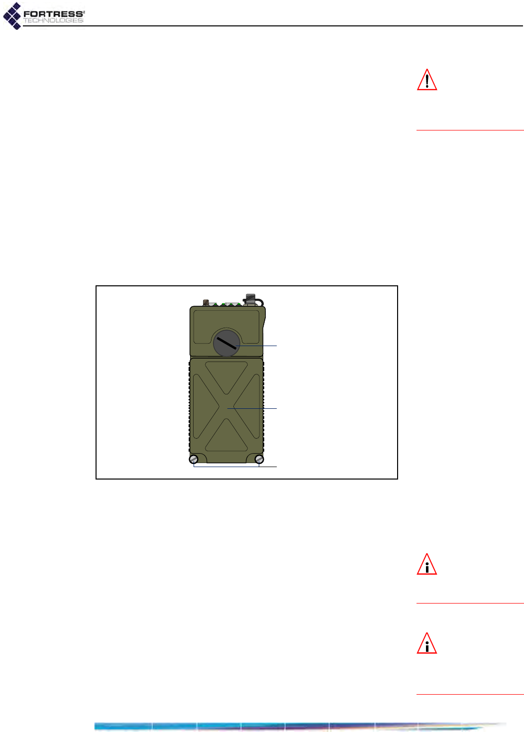
Figure 2.1. ES210 Battery Cover with Screws and Serial Port Cap
To install the battery for the first time:
1Unscrew the ES210 battery cover screws and lift the
battery cover (Figure 2.1).
NOTE: The battery
is keyed to install
in only the correct orien-
tation.
2Orient the battery so that the contacts are at the bottom and
facing back, with the corner cut situated on the lower right.
3Seat the battery squarely in the ES210 battery
compartment.
4Replace the battery cover and retighten the cover screws.
NOTE: The Battery
LED will not pro-
vide a charge indication
when the Mesh Point is
powered off.
5Connect the Mesh Point’s DC Power input to the power
adapter that shipped with the Mesh Point, and connect the
adapter to a properly rated AC power outlet.
6Permit the battery to fully charge, as indicated by a solid
green Battery LED, before using it for the first time.
(Complete LED indications are described in Section 3.1.1.)
battery cover
battery cover screws
serial port screw cap

ES210 Hardware Guide: Installation
6
Once the battery compartment is closed, you can power up and
operate the Mesh Point while the battery is charging.
2.1.2.2 Battery Charging and Power Requirements
The ES210 Mesh Point can operate normally while the battery
is charging. The battery charges up to 8.2 volts in a maximum
of 2.2 hours, with a maximum power consumption of 16 watts
(during simultaneous charging and operation). The ES210 will
auto-charge whether power is on or off (Section 3.2.1).
The wall-mounted power supply provides 12 volts at 2 amps
input current to simultaneously power and charge the ES210
Mesh Point.
Charge the battery at a maximum input current of 1.78 amps.
Do not exceed 30 volts on the Mesh Point’s 9-28V power
supply.
For safety, the Mesh Point prevents the battery from charging
when the temperature is outside the acceptable charging
range:
32º–113ºF (0º–45ºC) when the Mesh Point is powered off
23º–104º F (-5º–40ºC) when the Mesh Point is powered on
For maximum life, charge the battery at about 20º C (68º F).
2.1.2.3 Battery Storage and Longevity
For maximum life, store the battery, half charged, at about 20º
C (68º F).
Fully charged batteries lose less than 10% of their charge
when stored for six months at 73º F(23º C); less than 20%
when stored for three months at 113º F (45º C).
To prolong battery life:
Charge the battery early and often. However, if is not used
for a long time, store it at a half charge level.
Do not routinely "deep-cycle" the battery (frequently
discharge fully and recharge it).
Keep the battery cool, ideally in a refrigerator. High
temperatures (as found in a closed car, for instance) cause
lithium-ion batteries to degrade much more rapidly than if
not so exposed. In harsh thermal environments, consider
removing the battery when it is not in use and storing it in a
cool place so that it is not affected by the heat.
Do not freeze the battery. Most lithium ion battery
electrolytes freeze at approximately -40º F/C.
2.1.2.4 Replacing the Battery
If you need to obtain a replacement for the ES210 Mesh Point
battery, contact your Fortress Technologies representative.
1Power the Mesh Point down by depressing the Power Off
button on the right side of the chassis. If external power is
in use, disconnect the Mesh Point from the power source.
ES210 Hardware Guide: Installation
7
2Unscrew the battery cover screws and lift the battery cover
(Figure 2.1).
3Remove the existing battery.
4Fully seat the replacement battery in the compartment in
the correct orientation: contacts at the bottom and facing
back (into the compartment), corner notch situated on the
lower right.
5Replace the battery cover and retighten the cover screws.
6If the replacement battery has previously been in service (in
the current or another ES210), skip the rest of this
procedure.
or
If the replacement battery has never been used, connect
the Mesh Point’s DC Power input to the power adapter that
shipped with the Mesh Point, and connect the adapter to a
properly rated AC power outlet.
NOTE: The Battery
LED will not pro-
vide a charge indication
when the Mesh Point is
powered off.
7Permit the new battery to fully charge, as indicated by a
solid green Battery LED, before using it for the first time.
(Complete LED indications are described in Section 3.1.1.)
Once the battery compartment is closed, you can power up and
operate the Mesh Point while the battery is charging.
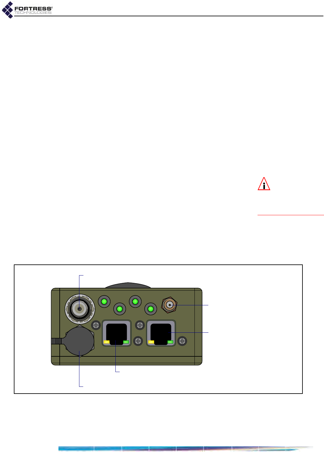
2.1.3 Port Locations
The ES210 Mesh Point’s power inlet and Ethernet and antenna
ports, along with the LED indicators, are located on the top
panel, shown below.
Figure 2.2. ES210 Mesh Point Port Locations
By default, Fortress Security (a.k.a. encryption) is enabled on
the WAN port and disabled on the Ethernet port. These and
other port settings are user configurable (see the Software GUI
Guide).
Wi-Fi antenna port (RP-TNC female)
GPS antenna port (SMA)
Ethernet port (RJ-45), default clear
WAN Ethernet port (RJ-45), default encrypted
DC power input (with tethered cap)

ES210 Hardware Guide: Installation
8
The Mesh Point's serial console port is located under the screw
cap on the front of the chassis, above the battery compartment,
as shown in Figure 2.1.
To access the port, use a screwdriver or similarly shaped object
(such as a key) to loosen the cap and then unscrew it. Be sure
to replace and tighten the cap securely when the port is not in
use. Refer to the Software CLI Guide for serial port settings.
2.2 Connecting the ES210
The ES210 can be connected temporarily to preconfigure the
Mesh Point software and then permanently for deployment.
2.2.1 Connections for Preconfiguration
Mesh Point software should be configured in advance of
deployment. This section provides instructions for temporarily
connecting the ES210 Mesh Point for preconfiguration.
If the Mesh Point will be powered with the battery, first follow
the instructions in Section 2.1.2.1.
1Position the Mesh Point so that it operates only within its
safe temperature range (14º–140º F/–10º–60º C).
CAUTION: To en-
sure optimal per-
formance, the battery
should be fully charged
before its initial use.
2If you are powering the Mesh Point with the internal battery,
install and fully charge the battery according to the
instructions in Section 2.1.2.1.
or
If you are powering the Mesh Point only through the DC
Power input, connect it to the power adapter that shipped
with the Mesh Point, and connect the adapter to a properly
rated AC power outlet.
3Connect the Mesh Point’s Ethernet port to a computer or
switch on the wired LAN.
4Power the Mesh Point on by depressing and holding for five
seconds the lower Power On button on the left side of the
chassis.
To complete the configuration, refer to the Software GUI Guide
or the Software CLI Guide for instructions on Logging On,
Licensing, and Configuring the Mesh Point.

ES210 Hardware Guide: Installation
9
WARNING: To
comply with FCC
regulations, antennas
must be professionally
installed and the install-
er is responsible for en-
suring compliance with
FCC limits.
2.2.2 Connections for Deployment
The section provides instructions for connecting the ES210 for
deployment after you have preconfigured the Mesh Point
software.
Review the Radio Frequency Safety Requirements (Section
2.1.1) before installing or operating the Mesh Point radio.
1If the deployed Mesh Point will be powered with the internal
battery and you have not yet done so, fully charge the
battery according to the instructions in Section 2.1.2.1.
or
If you are powering the Mesh Point only through the DC
Power input, connect it to the power adapter that shipped
with the Mesh Point, and connect the adapter to a properly
rated AC power outlet.
NOTE: Third par-
ty antennas are
subject to local regulato-
ry requirements. For
outdoor installations,
they must be water-
proof.
2If the Mesh Point’s internal radio will be used, connect an
omnidirectional antenna with a maximum gain of 5 dBi to
the Wi-Fi antenna port.
3If the Mesh Point’s GPS function will be used, connect an
antenna to the GPS antenna port.
4If the Mesh Point will be connected over Ethernet to a wired
LAN or to a remote device, connect the clear (by default)
Ethernet port to a switch on the wired LAN or to the remote
device.
2.3 Mounting the ES210
The ES210 Mesh Point can be worn or carried by a person on
foot, or it can be mounted on a vehicle or in a fixed position.
An ES210 Universal Mounting Kit for the ES210 Mesh Point is
optionally available from Fortress Technologies. The same kit
permits you to mount the ES210 on a mast, fix it to a flat
surface, or attach it magnetically to a smooth metal surface.
Mount the Mesh Point only where it will operate only within its
safe temperature range: 14º–140º F (–10º–60º C).
Regardless of how the ES210 will be mounted, you must
prepare the mounting bracket before attaching the ES210 to
the bracket. Follow the instructions appropriate for your
deployment.
ES210 Hardware Guide: Installation
10
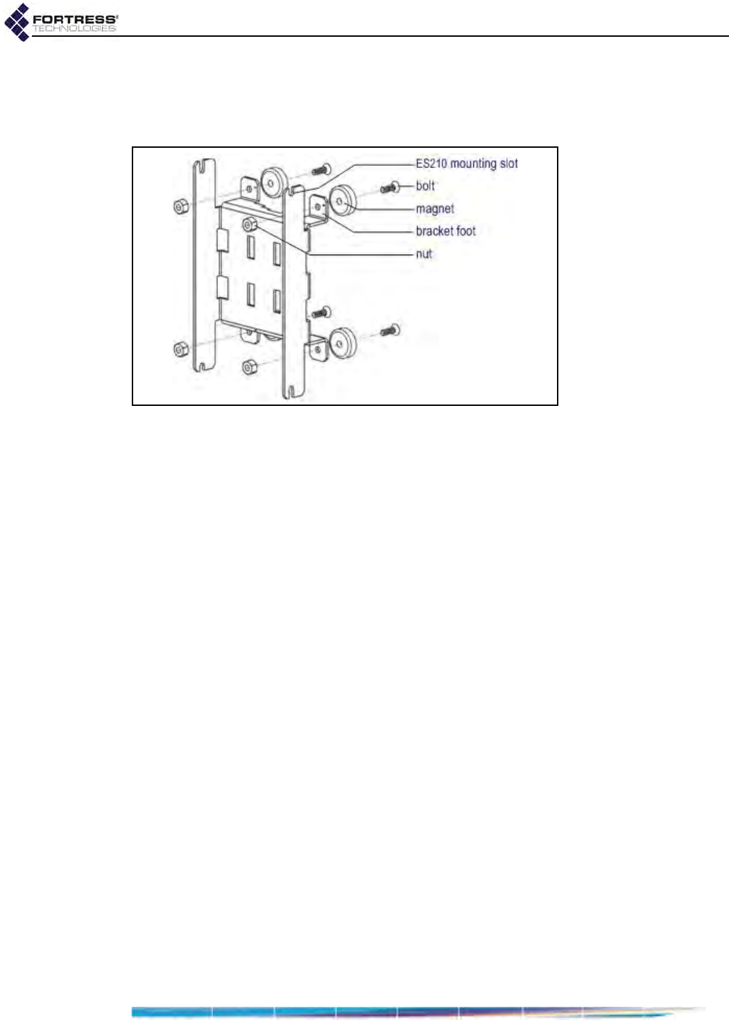
2.3.1 Magnetic Mounting
If you will be mounting the ES210 magnetically, first attach the
magnets to the feet on the bracket.
Figure 2.3. Attaching Magnets to the Mounting Bracket
1Identify four, each, of the magnets, bolts and nuts included
in the mounting kit (pictured above).
2Position a magnet with its flat side against the outer face of
one of the feet on the mounting bracket and the bolt holes
in the magnet and bracket foot aligned. When tightened,
the head of the bolt should fit into the depression on one
side of the magnet.
3Thread a bolt through the magnet and bracket foot and
secure the magnet to the bracket with a nut, tightening the
nut firmly with a 11/32" hex driver and a #2 Phillips driver.
4Repeat steps 2 and 3 for the remaining three magnets and
bracket feet.
5Attach the ES210 to the mounting bracket:
With two (of the four included) mounting screws
partially screwed into the top corners of the chassis,
hang the ES210 by the shafts of these screws on the
upper ES210 mounting slots in the bracket.
Install the remaining two mounting screws through the
lower mounting slots in the bracket and into the bottom
corners of the ES210 chassis.
Tighten all four mounting screws with a ¼" hex driver or
flat screwdriver.
6Mount the ES210-bracket assembly by placing the
magnetized feet of the bracket against a steel or iron
surface.
ES210 Hardware Guide: Installation
11
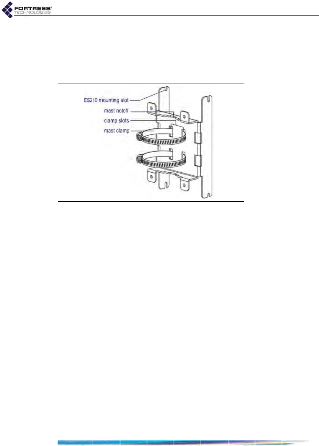
2.3.2 Mast Mounting
The ES210 Universal Mounting Kit accommodates masts from
1" to 3.5" in diameter.
If you will be mounting the ES210 on a mast, first attach the
mast clamps to the mounting bracket.
Figure 2.4. Attaching Mast Clamps to the Mounting Bracket
1Identify the two mast clamps included in the mounting kit
(pictured above).
2Guide one end of a mast clamp through two parallel clamp
slots in the bracket so that the open loop in the clamp and
its captive screw fastener are on the same side of the
mounting bracket as the bracket’s mast notches (as
shown).
3Repeat Step 2 for the second mast clamp.
4Attach the ES210 to the mounting bracket:
With two (of the four included) mounting screws
partially screwed into the top corners of the chassis,
hang the ES210 by the shafts of these screws on the
upper ES210 mounting slots in the bracket.
Install the remaining two mounting screws through the
lower mounting slots in the bracket and into the bottom
corners of the ES210 chassis.
Tighten all four mounting screws with a ¼" hex driver or
flat screwdriver.
5Mount the ES210 bracket assembly by fitting a mast
through the mast clamps and, using a flathead screwdriver,
tightening the clamps’ captive screw fasteners until the
mast notches in the bracket are clamped tight against the
mast.
ES210 Hardware Guide: Installation
12
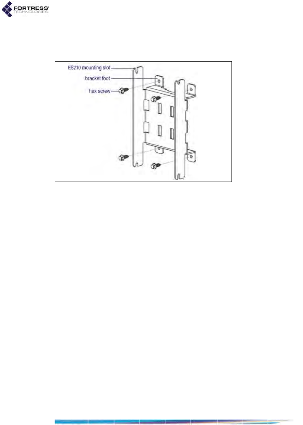
2.3.3 Non-Magnetic Surface Mounting
If you will be mounting the ES210 on a non-magnetic surface,
mount the bracket first, then attach the ES210 to the bracket.
Figure 2.5. Surface Mounting the Bracket before Attaching the ES210
1Obtain four #10 fasteners appropriate to the mounting
surface.
2Position the bracket where you want to mount it, with the
bracket feet flat against the mounting surface, and mark the
position of the holes in all four feet.
3If necessary, prepare the mounting surface by drilling holes
and, if appropriate, installing wall anchors at the mounting
positions you have marked.
4Align the holes in the feet of the mounting bracket with the
prepared mounting positions and secure the bracket to the
surface with the four #10 fasteners.
5Attach the ES210 to the mounting bracket:
With two (of the four included) mounting screws
partially screwed into the top corners of the chassis,
hang the ES210 by the shafts of these screws on the
upper ES210 mounting slots in the bracket.
Install the remaining two mounting screws through the
lower mounting slots in the bracket and into the bottom
corners of the ES210 chassis.
Tighten all four mounting screws with a ¼" hex driver or
flat screwdriver.
ES210 Hardware Guide: LEDs and Pushbutton Operation
13
Chapter 3
LEDs and Pushbutton Operation
NOTE:
There are
no LED indica-
tions in a Mesh Point in
blackout mode (see Sec-
tion 3.2.2).
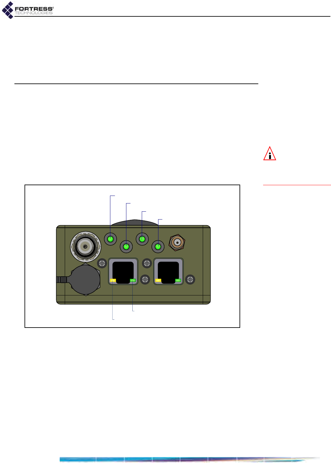
3.1 Top-Panel Indicators
The ES210 Mesh Point’s top panel features four system LEDs
(Power, Battery, Radio, Crypto,) and a pair of Link and Activity
LEDs for each of the ES210’s two Ethernet ports.
Figure 3.1. Fortress ES210 Mesh Point LED Indicators
3.1.1 System LEDs
Power
can exhibit:
solid green - Mesh Point is powered on and operating
normally.
off - Mesh Point is powered off.
slow-flash green - Mesh Point is booting.
fast-flash green - Battery was removed after Mesh Point
became operational.
power LED
crypto LED
battery LED
radio LED
port activity LED
port link LED

ES210 Hardware Guide: LEDs and Pushbutton Operation
14
NOTE:
The battery
will not charge
when the temperature is
outside the acceptable
charging range: 32º–
113ºF (0º–45ºC) when
the Mesh Point is pow-
ered off; 23º–104º F (-5º–
40ºC) when powered
on.
when powered by AC,
Battery
can exhibit:
solid green - Battery is fully charged.
off - Battery is charging.
when powered by battery,
Battery
can exhibit:
slow-flash green - Low Battery condition (below 6.3 V): the
Mesh Point will automatically power down five minutes after
Low Battery is first signaled (if external power is not
supplied first).
off - Mesh Point is powered off.
Radio
can exhibit:
solid green - Radio is on.
intermittent green - Mesh Point’s radio is passing traffic.
off - Radio is off or Mesh Point’s RF Kill function is enabled.
Crypto
can exhibit:
The Crypto LED is reserved for a future function on the
Mesh Point.
3.1.2 Port LEDs
The ES210 Mesh Point’s top-panel Ethernet ports are
equipped with link (lnk) and activity (Act) LEDs.
Lnk
can exhibit:
solid green - A link has been established for the port.
off - The port is not connected.
Act
can exhibit:
intermittent green - Traffic is passing on the link.
off - Traffic is not passing on the link.
Power Battery Radio Crypto
color behavior AC powered w/out AC power
green
solid normal
operation fully charged radio on
n/a
slow flash booting - low battery -
fast flash battery removed
during operation -- -
intermittent - - - passing traffic
off unit off charging unit off radio off or
RF kill activated
ES210 Hardware Guide: LEDs and Pushbutton Operation
15
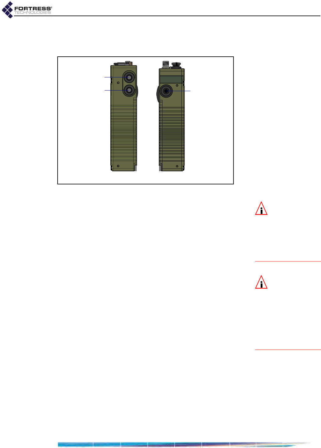
3.2 Pushbutton Operation
The ES210 Mesh Point is equipped with three push buttons.
Figure 3.2. ES210 Push Buttons
NOTE: If the Mesh
Point’s internal
temperature reaches
176ºF (80ºC) it powers
itself off. If you power it
up before the Mesh
Point has cooled, it will
again shutdown.
3.2.1 Powering the Mesh Point On and Off
When the ES210 Mesh Point is powered off, the lower button
on the left side of the chassis powers it on. The single button
on the right side of the chassis powers it off.
If the Mesh Point is off, press and hold the Power On button
for five seconds to turn it on.
The Power LED will slow-flash green while the Mesh Point
boots, then light solid green for normal operation.
NOTE: If the Mesh
Point is running
and the Power On but-
ton is pushed and held,
it toggles Blackout Mode
so the Mesh Point ap-
pears to be powered off.
If the unit has batteries,
this condition will drain
the batteries.
or
If the Mesh Point is on, press the Power Off button to turn it
off.
The Power LED will go dark.
3.2.1.1 Pushbutton Rebooting
Reboot (hard boot) the ES210 by powering it off and back on
again (described above).
3.2.2 Pushbutton Blackout Mode Operation
When the ES210 Mesh Point is powered on, the lower button
on the left side of the chassis turns the Mesh Point’s top-panel
LEDs off and on (Blackout Mode, Enabled/Disabled).
The default blackout mode setting is Disabled, in which state
the Mesh Point’s top-panel LEDs illuminate to indicate various
conditions. (LED behaviors and their associated meanings are
covered in Section 3.1.) Enabling blackout mode turns all top-
panel LEDs off.
rightleft
RF Kill
Power On/
Blackout Mode
Power Off
ES210 Hardware Guide: LEDs and Pushbutton Operation
16
NOTE: You can
also change the
Blackout Mode setting in
the Mesh Point GUI (see
the Software GUI Guide)
or in the Mesh Point CLI
(see the Software CLI
Guide).
If Blackout Mode is Disabled, the actions below will enable it. If
the setting is Enabled, the same steps will disable it.
1Press the lower button on the left side of the chassis.
2Hold it down for five seconds.
3Release the button.
The new setting persists over reboots and upgrades, just as
when changed through the Mesh Point GUI or CLI.
3.2.3 Pushbutton RF Kill Operation
NOTE: You can
also change the RF
Kill setting in the Mesh
Point GUI (see the Soft-
ware GUI Guide).
The upper button on the left side of the chassis toggles the
Mesh Point’s RF Kill function.
The default RF Kill setting is Disabled, in which state the Mesh
Point receives and transmits radio frequency signals normally.
Enabling RF Kill turns the Mesh Point’s internal radio off. When
RF Kill is enabled, the top-panel Radio LED lights solid green to
indicate that radio operation has been suspended.
If RF Kill is Disabled, the actions below will enable it. If the
setting is Enabled, the same steps will disable it.
1Press the upper button on the left side of the chassis.
2Hold it down for five seconds.
3Release the button.
The new setting persists over reboots and upgrades, just as
when changed through the Mesh Point GUI or CLI.
3.2.4 Pushbutton Restoring Defaults
To restore the Mesh Point’s configuration settings to their
factory-default values:
NOTE: You can
also restore the
Mesh Point’s factory de-
fault settings from the
Mesh Point GUI (see the
Software GUI Guide) and
the Mesh Point CLI (see
the Software CLI Guide).
1Simultaneously press the upper and lower buttons on the
left side of the Mesh Point chassis.
2Hold them down for at least ten seconds.
3Release both buttons.
After you have successfully initiated the restore operation, the
Mesh Point will reboot automatically.
After booting, the Mesh Point LEDs will resume normal
operation and all configuration settings, including the IP
address of the Mesh Point’s management interface will be at
their factory-default values.

ES210 Hardware Guide: Specifications
17
Chapter 4
Specifications
4.1 Hardware Specifications
4.1.1 Physical Specifications
form factor: compact, wearable, mountable
dimensions: 7" H x 3.3" W x 1.7" D
(17.8 cm × 8.4cm × 4.3 cm, approx.)
weight: 2.1 lbs. (.95 kg, approx.)
power supply: 9-30 V DC input (w/ internal resettable fuse)
7.4 V removable/rechargeable lithium ion polymer battery (optional)
connections:
two waterproof RJ-45 10/100 Mbps Ethernet ports with auto-MDIX
one cylindrical 3-pin serial port
one RP-TNC antenna port (female)
one SMA antenna port for GPS receiver (female, passive or active)
one weatherized 9-30V DC power input port with tethered cap
radio: 802.11a/b/g/n
indicators: four top-panel system LEDs (Green/Amber):
Power, Battery, Radio, Crypto
two pairs integrated port Link and Activity LEDs
controls: three push buttons (usable wearing gloves)

ES210 Hardware Guide: Specifications
18
4.1.2 Battery Specifications
4.1.3 Environmental Specifications
If the Mesh Point’s internal temperature reaches 176ºF (80ºC)
it powers itself off. If you power it up before the Mesh Point has
cooled, it will again shutdown.
4.1.4 Compliance and Standards
The Fortress ES210 is certified by the Wi-Fi Alliance® for the
following standards:
capacity: 7.4 V (nominal); 4 Ah (29 Wh)
cells: 2 Series lithium ion polymer
charging:
input up to 8.2V at 1.78 input current maximum (.45 capacity)
max. time 3 hrs
temperature 32º–113º F (0º–45º C) when unit is powered off
23º–104º F (-5º–40ºC) when unit is powered on
storage: 6 mos. at 73º F(23º C) < 10% capacity loss
3 mos. at 113º F (45º C) < 20% capacity loss
replacement: 500 charge cycles minimum
power draw: 6 W (charging)
16 W maximum (operating while charging)
maximum heat dissipation: 20.5 BTU/hr
cooling: convection
operating temperature: 14º–140º F (-10º–60º C)
operating relative humidity
(non-condensing): 5%–95%
storage temperature: 14º–140º F (-10º–60º C)
emissions: FCC Class A, part C;
MIL-STD 461F
immunity: MIL-STD 461F
vibration: MIL-STD 810G
IEEE: 802.11a/b/g
security: WPA™, WPA2™—Personal and Enterprise
EAP types: EAP-TLS, EAP-TTLS/MSCHAPv2,
PEAPv0/EAP-MSCHAPv2, PEAPv1/EAP-GTC,
EAP-SIM, EAP-AKA, EAP-FAST
ES210 Hardware Guide: Specifications
19
4.2 DB9-to-3-pin Console Port Adapter
A DB9-to-3-pin cylindrical adapter is required in order to
connect the Mesh Point’s Console port to a DB9 terminal
connection.
Table 4.1 shows the adapter pin-outs.
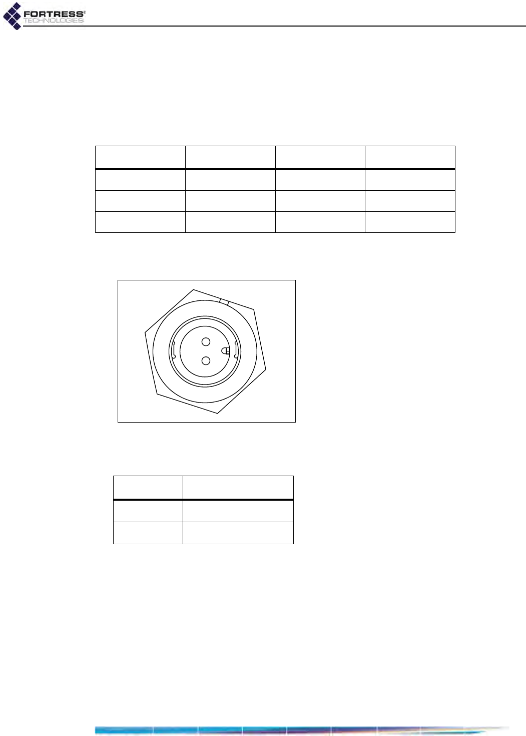
4.3 2-Pin DC Input Connector
The Mesh Point uses a 2-pin connector to input power.
Figure 4.1. 2-pin Power Connector Pins
Table 4.2 shows the power connector pin-outs.
Table 4.1. DB9-to-3-pin Cylindrical Adapter Pin-Outs
Description cylindrical pin DB9 pin standard color
Ground 1 5 red
Tx 2 2 black
Rx 3 3 white or green
1
2
Table 4.2. ES210 DC Power Connector Pin-Outs
pin signal
1+9 to 30 VDC
2Ground

ES210 Hardware Guide: Index
I
Index
A
antennas
installing 9
ports
location 7
specifications 17
restrictions ii
B
battery 1–7
charging 6
installation 5
LED 14
safety requirements 4
specifications 18
storage 6
blackout mode 15–16
button operation 15–16
C
charging the battery 6
chassis push buttons 15–16
compliance i, 18
connections
see ports
Console port location 7
D
default
restoring defaults 16
dimensions 17
E
emissions compliance 18
environmental specifications 17
Ethernet ports
location 7
specifications 17
F
FCC
see compliance
fuse 4, 17
H
hardware
mounting kit 9–12
safety requirements 3–4
specifications 17
see also ports
I
installation 8–9
chassis mounting 9–12
safety requirements 3–4
interference i
L
LEDs 13–14
blackout mode 15–16
M
mounting kit 9–12
O
operating temperature 3, 18
P
Pin-outs
DB9-to-3-Pin adapter 19
ES210 DC power connector 19
ports
locations 7
serial port adapter 19
precautions
see safety, requirements
pushbutton operation 15–16
R
radios 2
precautions 4
RF kill 16
safety requirements 4
recharging the battery 6
resetting
factory defaults 16