Fortress Technologies ES210 The ES210 is a single radio access point/bridge. User Manual ES210 Secure Wireless Bridge User Guide DRAFT
Fortress Technologies, Inc. The ES210 is a single radio access point/bridge. ES210 Secure Wireless Bridge User Guide DRAFT
Contents
Manual

Fortress Security System
ES210
Secure Wireless Bridge
User Guide
www.fortresstech.com
© 2009 Fortress Technologies
D R A F T D O C U M E N T

Fortress ES210
i
Fortress ES210 Secure Wireless Bridge 5.2
Copyright © 2009 Fortress Technologies, Inc. All rights reserved.
This document contains proprietary information protected by copyright. No part of this
document may be reproduced or transmitted in any form or by any means, electronic or
mechanical, without written permission of Fortress Technologies, 4023 Tampa Road, Suite
2000, Oldsmar, FL 34677, except as specified in the Product Warranty and License Terms.
FORTRESS TECHNOLOGIES, INC., MAKES NO WARRANTY OF ANY KIND WITH
REGARD TO THIS MATERIAL, INCLUDING BUT NOT LIMITED TO THE IMPLIED
WARRANTIES OF MERCHANTABILITY AND FITNESS FOR A PARTICULAR PURPOSE.
FORTRESS TECHNOLOGIES, INC. SHALL NOT BE LIABLE FOR ERRORS
CONTAINED HEREIN OR FOR INCIDENTAL OR CONSEQUENTIAL DAMAGES IN
CONNECTION WITH THE FURNISHING, PERFORMANCE OR USE OF THIS
MATERIAL. THE INFORMATION IN THIS DOCUMENT IS SUBJECT TO CHANGE
WITHOUT NOTICE.
The Fortress Technologies and AirFortress logos and AirFortress and are registered
trademarks; Multi-Factor Authentication, Unified Security Model, Wireless Link Layer
Security and Three Factor Authentication (TFA) are trademarks of Fortress Technologies,
Inc. The technology behind Wireless Link Layer Security™ enjoys U.S. and international
patent protection under patent number 5,757,924.
Portions of this software are covered by the GNU General Public License (GPL) Copyright
© 1989, 1991 Free Software Foundation, Inc,. 59 Temple Place, Suite 330, Boston, MA
02111-1307 USA.
To receive a complete machine-readable copy of the corresponding source code on CD,
send $10 (to cover the costs of production and mailing) to: Fortress Technologies; 4023
Tampa Road, suite 2000; Oldsmar, FL 34677-3216. Please be sure to include a copy of
your Fortress Technologies invoice and a valid “ship to” address.
This product includes cryptographic software written by Eric Young (eay@cryptsoft.com).
This product includes software written by Tim Hudson (tjh@cryptsoft.com).
Copyright © 1995-1998 Eric Young (eay@cryptsoft.com) All rights reserved.
This package is an SSL implementation written by Eric Young (eay@cryptsoft.com). The
implementation was written so as to conform with Netscape’s SSL.
THIS SOFTWARE IS PROVIDED BY ERIC YOUNG ``AS IS'' AND ANY EXPRESS OR
IMPLIED WARRANTIES, INCLUDING, BUT NOT LIMITED TO, THE IMPLIED
WARRANTIES OF MERCHANTABILITY AND FITNESS FOR A PARTICULAR PURPOSE
ARE DISCLAIMED. IN NO EVENT SHALL THE AUTHOR OR CONTRIBUTORS BE
LIABLE FOR ANY DIRECT, INDIRECT, INCIDENTAL, SPECIAL, EXEMPLARY, OR
CONSEQUENTIAL DAMAGES (INCLUDING, BUT NOT LIMITED TO, PROCUREMENT
OF SUBSTITUTE GOODS OR SERVICES; LOSS OF USE, DATA, OR PROFITS; OR
BUSINESS INTERRUPTION) HOWEVER CAUSED AND ON ANY THEORY OF
LIABILITY, WHETHER IN CONTRACT, STRICT LIABILITY, OR TORT (INCLUDING
NEGLIGENCE OR OTHERWISE) ARISING IN ANY WAY OUT OF THE USE OF THIS
SOFTWARE, EVEN IF ADVISED OF THE POSSIBILITY OF SUCH DAMAGE.
Atheros, the Atheros logo, Atheros Driven, Driving the wireless future, Super G and Super
AG are all registered trademarks of Atheros Communications. ROCm, JumpStart for
Wireless, Atheros XR, Wake-on-Wireless, Wake-on-Theft, and FastFrames, are all
trademarks of Atheros Communications, Inc.
This product uses Dynamic Host Control Protocol copyright 1995, 1996, 1997, 1998, 1999
by the Internet Software Consortium-DHCP. All rights reserved.
This product includes software developed by the OpenSSL Project for use in the OpenSSL
Toolkit. (http://www.openssl.org/)
Copyright © 1998-2007 The OpenSSL Project. All rights reserved.THIS SOFTWARE IS
PROVIDED BY THE OpenSSL PROJECT ``AS IS'' AND ANY EXPRESSED OR IMPLIED
WARRANTIES, INCLUDING, BUT NOT LIMITED TO, THE IMPLIED WARRANTIES OF
MERCHANTABILITY AND FITNESS FOR A PARTICULAR PURPOSE ARE
DISCLAIMED. IN NO EVENT SHALL THE OpenSSL PROJECT OR ITS CONTRIBUTORS
BE LIABLE FOR ANY DIRECT, INDIRECT, INCIDENTAL, SPECIAL, EXEMPLARY, OR
D R A F T D O C U M E N T

Fortress ES210
ii
CONSEQUENTIAL DAMAGES (INCLUDING, BUT NOT LIMITED TO, PROCUREMENT
OF SUBSTITUTE GOODS OR SERVICES; LOSS OF USE, DATA, OR PROFITS; OR
BUSINESS INTERRUPTION) HOWEVER CAUSED AND ON ANY THEORY OF
LIABILITY, WHETHER IN CONTRACT, STRICT LIABILITY, OR TORT (INCLUDING
NEGLIGENCE OR OTHERWISE) ARISING IN ANY WAY OUT OF THE USE OF THIS
SOFTWARE, EVEN IF ADVISED OF THE POSSIBILITY OF SUCH DAMAGE.
This product uses Net-SNMP Copyright © 1989, 1991, 1992 by Carnegie Mellon
University, Derivative Work - 1996, 1998-2000. Copyright © 1996, 1998-2000 The Regents
of the University of California. All rights reserved. Copyright © 2001-2003, Cambridge
Broadband Ltd. All rights reserved. Copyright © 2003 Sun Microsystems, Inc. All rights
reserved. Copyright © 2001-2006, Networks Associates Technology, Inc. All rights
reserved. Center of Beijing University of Posts and Telecommunications. All rights
reserved.
Licensed under the Apache License, Version 2.0 (the "License"); you may not use this file
except in compliance with the License. You may obtain a copy of the License at http://
www.apache.org/licenses/LICENSE-2.0. Unless required by applicable law or agreed to in
writing, software distributed under the License is distributed on an "AS IS" BASIS,
WITHOUT WARRANTIES OR CONDITIONS OF ANY KIND, either express or implied.
See the License for the specific language governing permissions and limitations under the
License.
Microsoft and Windows are registered trademarks of the Microsoft Corporation.
Firefox is a trademark of the Mozilla Foundation.
SSH is a trademark of SSH Communication Security.
All other trademarks mentioned in this document are the property of their respective
owners.
FCC EMISSIONS COMPLIANCE STATEMENT
THIS EQUIPMENT HAS BEEN TESTED AND FOUND TO COMPLY
WITH THE LIMITS FOR A CLASS A DIGITAL DEVICE, PURSUANT TO
PART 15 OF THE FCC RULES. THESE LIMITS ARE DESIGNED TO
PROVIDE REASONABLE PROTECTION AGAINST HARMFUL
INTERFERENCE WHEN THE EQUIPMENT IS OPERATED IN A
COMMERCIAL ENVIRONMENT. THIS EQUIPMENT GENERATES,
USES, AND CAN RADIATE RADIO FREQUENCY ENERGY AND, IF
NOT INSTALLED AND USED IN ACCORDANCE WITH THE
INSTRUCTION MANUAL, MAY CAUSE HARMFUL INTERFERENCE TO
RADIO COMMUNICATIONS. OPERATION OF THIS EQUIPMENT IN A
RESIDENTIAL AREA IS LIKELY TO CAUSE HARMFUL
INTERFERENCE IN WHICH CASE THE USER WILL BE REQUIRED TO
CORRECT THE INTERFERENCE AT HIS OWN EXPENSE.
THIS DEVICE COMPLIES WITH PART 15 OF THE FCC RULES.
OPERATION IS SUBJECT TO THE FOLLOWING TWO CONDITIONS:
(1) THIS DEVICE MAY NOT CAUSE HARMFUL INTERFERENCE, AND
(2) THIS DEVICE MUST ACCEPT INTERFERENCE THAT MAY CAUSE
UNDESIRED OPERATION.
D R A F T D O C U M E N T

Fortress ES210
iii
FCC CLASS A WARNING
MODIFYING THE EQUIPMENT WITHOUT FORTRESS
AUTHORIZATION MAY RESULT IN THE EQUIPMENT NO LONGER
COMPLYING WITH FCC REQUIREMENTS FOR CLASS A DIGITAL
DEVICES. IN THAT EVENT, YOUR AUTHORITY TO USE THE
EQUIPMENT MAY BE VOIDED UNDER FCC REGULATIONS, AND YOU
MAY BE REQUIRED TO CORRECT ANY INTERFERENCE TO RADIO
OR TELEVISION COMMUNICATIONS AT YOUR OWN EXPENSE.
TO COMPLY WITH FCC RF EXPOSURE COMPLIANCE
REQUIREMENTS, THE ANTENNAS USED FOR THESE
TRANSMITTERS MUST BE INSTALLED TO PROVIDE A SEPARATION
DISTANCE OF AT LEAST 20 CM FROM ALL PERSONS AND MUST
NOT BE CO-LOCATED OR OPERATED IN CONJUNCTION WITH ANY
OTHER ANTENNA OR TRANSMITTER.
WARNING:FORTRESS IS NOT RESPONSIBLE FOR ANY RADIO
OR TELEVISION INTERFERENCE CAUSED BY UNAUTHORIZED
MODIFICATION OF THE DEVICES INCLUDED WITH THE SECURE
WIRELESS ACCESS BRIDGE, OR THE SUBSTITUTION OR
ATTACHMENT OF CONNECTING CABLES AND EQUIPMENT OTHER
THAN THAT SPECIFIED BY FORTRESS. THE CORRECTION OF
INTERFERENCE CAUSED BY SUCH UNAUTHORIZED
MODIFICATION, SUBSTITUTION OR ATTACHMENT IS THE
RESPONSIBILITY OF THE USER. FORTRESS IS NOT LIABLE FOR
ANY DAMAGE OR VIOLATION OF GOVERNMENT REGULATIONS
THAT MAY ARISE FROM THE USER FAILING TO COMPLY WITH
THESE GUIDELINES.
ANTENNA RESTRICTIONS
THIS DEVICE HAS BEEN DESIGNED TO OPERATE WITH THE
ANTENNAS LISTED BELOW AND TO HAVE A MAXIMUM GAIN OF
5 dB. ANTENNAS NOT INCLUDED IN THIS LIST OR HAVING A GAIN
GREATER THAN 5 dB ARE STRICTLY PROHIBITED FOR USE WITH
THIS DEVICE. THE REQUIRED ANTENNA IMPEDANCE IS 50 OHMS.
Supported Detachable Antennas
Antenna Manufacturer Model
5 dBi rubber duck Airline™ WAG-5AG
2 dBi rubber duck Terrawave® M7020030MR10002
D R A F T D O C U M E N T

Fortress ES210
iv
End User License Agreement (EULA)
IMPORTANT; PLEASE READ THIS END USER LICENSE AGREEMENT CAREFULLY.
DOWNLOADING, INSTALLING OR USING FORTRESS TECHNOLOGIES SOFTWARE
CONSTITUTES ACCEPTANCE OF THIS AGREEMENT.
FORTRESS TECHNOLOGIES, INC., WILL LICENSE ITS SOFTWARE TO YOU THE
CUSTOMER (END USER) ONLY UPON THE CONDITION THAT YOU ACCEPT ALL OF
THE TERMS CONTAINED IN THIS END USER LICENSE AGREEMENT. THE ACT OF
DOWNLOADING, INSTALLING, OR USING FORTRESS SOFTWARE, BINDS YOU AND
THE BUSINESS THAT YOU REPRESENT (COLLECTIVELY, “CUSTOMER”) TO THE
AGREEMENT.
License
Fortress grants to Customer (“Licensee”) a non-exclusive and non-transferable right to use
the Fortress Software Product (“Software”) described in the Fortress Product Description
for which Customer has paid any required license fees and subject to the use rights and
limitations in this Agreement. Unless otherwise agreed to in writing, use of the Software is
limited to the number of authorized users for which Licensee has purchased the right to the
use of the software. Software is authorized for installation on any Fortress approved
device. “Software” includes computer program(s) and any documentation (whether
contained in user manuals, technical manuals, training materials, specifications, etc.) that
is included with the software (including CD-ROM, or on-line). Software is authorized for
installation on a single use computing device such as Fortress hardware platform,
computer, laptop, PDA or any other computing device. Software is not licensed for
installation or embedded use on any other system(s) controlling access to a secondary
network of devices or securing access for any separate computing devices. Software
contains proprietary technology of Fortress or third parties. No ownership in or title to the
Software is transferred. Software is protected by copyright laws and international treaties.
Customer may be required to input a software license key to initialize the software
installation process.
Customer may make backup or archival copies of Software and use Software on a backup
processor temporarily in the event of a processor malfunction. Any full or partial copy of
Software must include all copyright and other proprietary notices which appear on or in the
Software. Control functions may be installed and enabled. Customer may not modify
control utilities. Customer may not disclose or make available Software to any other party
or permit others to use it except Customer's employees and agents who use it on
Customer's behalf and who have agreed to these license terms. Customer may not transfer
the software to another party except with Fortress' written permission. Customer agrees
not to reverse engineer, decompile, or disassemble the Software. Customer shall maintain
adequate records matching the use of Software to license grants and shall make the
records available to Fortress or the third party developer or owner of the Software on
reasonable notice. Fortress may terminate any license granted hereunder if Customer
breaches any license term. Upon termination of the Agreement, Customer shall destroy or
return to Fortress all copies of Software.
General Limitations
This is a License for the use of Fortress Software Product and documentation; it is not a
transfer of title. Fortress retains ownership of all copies of the Software and
Documentation. Customer acknowledges that Fortress or Fortress Solution Provider trade
secrets are contained within the Software and Documentation. Except as otherwise
expressly provided under the Agreement, Customer shall have no right and Customer
specifically agrees not to:
i.Transfer, assign or sublicense its license rights to any other person or entity and
Customer acknowledges that any attempt to transfer, assign or sublicense shall “void” the
license;
ii.Make modifications to or adapt the Software or create a derivative work based on the
Software, or permit third parties to do the same;
iii.Reverse engineer, decompile, or disassemble the Software to a human-readable form,
except to the extent otherwise expressly permitted under applicable law notwithstanding
this restriction and;
D R A F T D O C U M E N T

Fortress ES210
v
iv.Disclose, provide, or otherwise make available trade secrets contained within the
Software and Documentation in any form to any third party without the prior written consent
of Fortress Technologies. Customer shall implement reasonable security measures to
protect such trade secrets.
Software, Upgrades and Additional Copies
For purposes of the Agreement, “Software” shall include computer programs, including
firmware, as provided to Customer by Fortress or a Fortress Solution Provider, and any (a)
bug fixes, (b) maintenance releases, (c) minor and major upgrades as deemed to be
included under this agreement by Fortress or backup copies of any of the foregoing.
NOTWITHSTANDING ANY OTHER PROVISION OF THE AGREEMENT:
i.CUSTOMER HAS NO LICENSE OR RIGHT TO MAKE OR USE ANY ADDITIONAL
COPIES OR UPGRADES UNLESS CUSTOMER, AT THE TIME OF MAKING OR
ACQUIRING SUCH COPY OR UPGRADE, ALREADY HOLDS A VALID LICENSE TO
THE ORIGINAL SOFTWARE AND HAS PAID THE APPLICABLE FEE FOR THE
UPGRADE OR ADDITIONAL COPIES;
ii.USE OF UPGRADES IS LIMITED TO FORTRESS EQUIPMENT FOR WHICH
CUSTOMER IS THE ORIGINAL END USER CUSTOMER OR LESSEE OR OTHERWISE
HOLDS A VALID LICENSE TO USE THE SOFTWARE WHICH IS BEING UPGRADED;
AND;
iii.THE MAKING AND USE OF ADDITIONAL COPIES IS LIMITED TO NECESSARY
BACKUP PURPOSES ONLY.
Proprietary Notices
All copyright and other proprietary notices on all copies of the Software shall be maintained
and reproduced by the Customer in the same manner that such copyright and other
proprietary notices are included on the Software. Customer shall not make any copies or
duplicates of any Software without the prior written permission of Fortress; except as
expressly authorized in the Agreement.
Term and Termination
This Agreement and License shall remain in effect until terminated through one of the
following circumstances:
i.Agreement and License may be terminated by the Customer at any time by destroying all
copies of the Software and any Documentation.
ii.Agreement and License may be terminated by Fortress due to Customer non-compliance
with any provision of the Agreement.
Upon termination by either the Customer or Fortress, the Customer shall destroy or return
to Fortress all copies of Software and Documentation in its possession or control. All
limitations of liability, disclaimers, restrictions of warranty, and all confidentiality obligations
of Customer shall survive termination of this Agreement. Also, the provisions set-forth in
the sections titled “U.S. Government Customers” and “General Terms Applicable to the
Limited Warranty Statement and End User License Agreement” shall survive termination of
the Agreement.
Customer Records
Fortress and its independent accountants reserve the right to conduct an audit of Customer
records to verify compliance with this agreement. Customer grants to Fortress and its
independent accountants access to its books, records and accounts during Customer's
normal business hours in support of such an audit. Customer shall pay to Fortress the
appropriate license fees, plus the reasonable cost of conducting the audit should an audit
disclose non-compliance with this Agreement.
Export Restrictions
Customer acknowledges that the laws and regulations of the United States restrict the
export and re-export of certain commodities and technical data of United States origin,
including the Product, Software and the Documentation, in any medium. Customer will not
knowingly, without prior authorization if required, export or re-export the Product, Software
or the Documentation in any medium without the appropriate United States and foreign
D R A F T D O C U M E N T

Fortress ES210
vi
government licenses. The transfer or export of the software outside the U.S. may require a
license from the Bureau of Industry and Security. For questions call BIS at 202-482-4811.
U.S Government Customers
The Software and associated documentation were developed at private expense and are
delivered and licensed as “commercial computer software” as defined in DFARS 252.227-
7013, DFARS 252.227-7014, or DFARS 252.227-7015 as a “commercial item” as defined
in FAR 2.101(a), or as “Restricted computer software” as defined in FAR 52.227-19. All
other technical data, including manuals or instructional materials, are provided with
“Limited Rights” as defined in DFAR 252.227-7013 (a) (15), or FAR 52.227-14 (a) and in
Alternative II (JUN 1987) of that clause, as applicable.
Limited Warranty
The warranties provided by Fortress in this Statement of Limited Warranty apply only to
Fortress Products purchased from Fortress or from a Fortress Solution Provider for internal
use on Customer's computer network. “Product” means a Fortress software product,
upgrades, or firmware, or any combination thereof. The term “Product” also includes
Fortress software programs, whether pre-loaded with the Fortress hardware Product,
installed subsequently or otherwise. Unless Fortress specifies otherwise, the following
warranties apply only in the country where Customer acquires the Product. Nothing in this
Statement of Warranty affects any statutory rights of consumers that cannot be waived or
limited by contract.
Customer is responsible for determining the suitability of the Products in Customer's
network environment. Unless otherwise agreed, Customer is responsible for the Product's
installation, set-up, configuration, and for password and digital signature management.
Fortress warrants the Products will conform to the published specifications and will be free
of defects in materials and workmanship. Customer must notify Fortress within the
specified warranty period of any claim of such defect. The warranty period for software is
one (1) year commencing from the ship date to Customer [and in the case of resale by a
Fortress Solution Provider, commencing not more than (90) days after original shipment by
Fortress]. Date of shipment is established per the shipping document (packing list) for the
Product that is shipped from Fortress location.
Customer shall provide Fortress with access to the Product to enable Fortress to diagnose
and correct any errors or defects. If the Product is found defective by Fortress, Fortress'
sole obligation under this warranty is to remedy such defect at Fortress' option through
repair, upgrade or replacement of product. Services and support provided to diagnose a
reported issue with a Fortress Product, which is then determined not to be the root cause of
the issue, may at Fortress’ option be billed at the standard time and material rates.
Warranty Exclusions
The warranty does not cover Fortress Hardware Product or Software or any other
equipment upon which the Software is authorized by Fortress or its suppliers or licensors,
which (a) has been damaged through abuse or negligence or by accident, (b) has been
altered except by an authorized Fortress representative, (c) has been subjected to
abnormal physical or electrical stress (i.e., lightning strike) or abnormal environmental
conditions, (d) has been lost or damaged in transit, or (e) has not been installed, operated,
repaired or maintained in accordance with instructions provided by Fortress.
The warranty is voided by removing any tamper evidence security sticker or marking
except as performed by a Fortress authorized service technician.
Fortress does not warrant uninterrupted or error-free operation of any Products or third
party software, including public domain software which may have been incorporated into
the Fortress Product.
Fortress will bear no responsibility with respect to any defect or deficiency resulting from
accidents, misuse, neglect, modifications, or deficiencies in power or operating
environment.
Unless specified otherwise, Fortress does not warrant or support non-Fortress products. If
any service or support is rendered such support is provided WITHOUT WARRANTIES OF
ANY KIND.
D R A F T D O C U M E N T

Fortress ES210
vii
DISCLAIMER OF WARRANTY
THE WARRANTIES HEREIN ARE SOLE AND EXCLUSIVE, AND NO OTHER
WARRANTY, WHETHER WRITTEN OR ORAL, IS EXPRESSED OR IMPLIED. TO THE
EXTENT PERMITTED BY LAW, FORTRESS SPECIFICALLY DISCLAIMS THE IMPLIED
WARRANTIES OF MERCHANTABILITY, FITNESS FOR A PARTICULAR PURPOSE,
TITLE AND NONINFRINGEMENT.
General Terms Applicable to the Limited Warranty and End User License Agreement
Disclaimer of Liabilities
THE FOREGOING WARRANTIES ARE THE EXCLUSIVE WARRANTIES AND REPLACE
ALL OTHER WARRANTIES OR CONDITIONS, EXPRESS OR IMPLIED, INCLUDING,
BUT NOT LIMITED TO, THE IMPLIED WARRANTIES OR CONDITIONS OF
MERCHANTABILITY AND FITNESS FOR A PARTICULAR PURPOSE. FORTRESS
SHALL HAVE NO LIABILITY FOR CONSEQUENTIAL, EXEMPLARY, OR INCIDENTAL
DAMAGES EVEN IF IT HAS BEEN ADVISED OF THE POSSIBILITY OF SUCH
DAMAGES. THE STATED LIMITED WARRANTY IS IN LIEU OF ALL LIABILITIES OR
OBLIGATIONS OF FORTRESS FOR DAMAGES ARISING OUT OF OR IN CONNECTION
WITH THE DELIVERY, USE, OR PERFORMANCE OF THE PRODUCTS (HARDWARE
AND SOFTWARE). THESE WARRANTIES GIVE SPECIFIC LEGAL RIGHTS AND
CUSTOMER MAY ALSO HAVE OTHER RIGHTS WHICH VARY FROM JURISDICTION
TO JURISDICTION. SOME JURISDICTIONS DO NOT ALLOW THE EXCLUSION OR
LIMITATION OF EXPRESS OR IMPLIED WARRANTIES, SO THE ABOVE EXCLUSION
OR LIMITATION MAY NOT APPLY TO YOU. IN THAT EVENT, SUCH WARRANTIES ARE
LIMITED IN DURATION TO THE WARRANTY PERIOD. NO WARRANTIES APPLY
AFTER THAT PERIOD.
Product Warranty and License Terms
Indemnification
Fortress will defend any action brought against Customer based on a claim that any
Fortress Product infringes any U.S. patents or copyrights excluding third party software,
provided that Fortress is immediately notified in writing and Fortress has the right to control
the defense of all such claims, lawsuits, and other proceedings. If, as a result of any claim
of infringement against any U.S. patent or copyright, Fortress is enjoined from using the
Product, or if Fortress believes the Product is likely to become the subject of a claim of
infringement, Fortress at its option and expense may procure the right for Customer to
continue to use the Product, or replace or modify the Product so as to make it non-
infringing. If neither of these two options is reasonably practicable, Fortress may
discontinue the license granted herein on one month's written notice and refund to
Licensee the unamortized portion of the license fees hereunder. The depreciation shall be
an equal amount per year over the life of the Product as established by Fortress. The
foregoing states the entire liability of Fortress and the sole and exclusive remedy of the
Customer with respect to infringement of third party intellectual property.
Limitation of Liability
Circumstances may arise where, because of a default on Fortress' part or other liability,
Customer is entitled to recover damages from Fortress. In each such instance, regardless
of the basis on which you are entitled to claim damages from Fortress (including
fundamental breach, negligence, misrepresentation, or other contract or tort claim),
Fortress is liable for no more than damages for bodily injury (including death) and damage
to real property and tangible personal property, and the amount of any other actual direct
damages, up to either U.S. $25,000 (or equivalent in local currency) or the charges (if
recurring, 12 months' charges apply) for the Product that is the subject of the claim,
whichever is less. This limit also applies to Fortress' Solution Providers. It is the maximum
for which Fortress and its Solution Providers are collectively responsible.
UNDER NO CIRCUMSTANCES IS FORTRESS LIABLE FOR ANY OF THE FOLLOWING:
1) THIRD-PARTY CLAIMS AGAINST YOU FOR DAMAGES,
2) LOSS OF, OR DAMAGE TO, YOUR RECORDS OR DATA, OR
3) SPECIAL, INCIDENTAL, OR INDIRECT DAMAGES OR FOR ANY ECONOMIC
CONSEQUENTIAL DAMAGES (INCLUDING LOST PROFITS OR SAVINGS), EVEN IF
D R A F T D O C U M E N T

Fortress ES210
viii
FORTRESS OR ITS SOLUTION PROVIDER IS INFORMED OF THEIR POSSIBILITY.
SOME JURISDICTIONS DO NOT ALLOW THE EXCLUSION OR LIMITATION OF
INCIDENTAL OR CONSEQUENTIAL DAMAGES, SO THE ABOVE LIMITATION OR
EXCLUSION MAY NOT APPLY TO CUSTOMER.
Telephone Support
During the warranty period, Fortress or its Solution Provider will provide a reasonable
amount of telephone consultation to the Customer. This support shall include assistance in
connection with the installation and routine operation of the Product, but does not include
network troubleshooting, security consultation, design and other services outside of the
scope of routine Product operation. Warranty services for the Products shall be available
during Fortress' normal U.S. (EST) business days and hours.
Extended Warranty Service
If the Customer purchases an extended warranty service agreement with Fortress, service
will be provided in accordance to said agreement's terms and conditions.
Access and Service
Customer must provide Fortress or Solution Provider with access to the Product to enable
Fortress or Solution Provider to provide the service. Access may include access via the
Internet, on-site access or Customer shall be responsible for returning the Product to
Fortress or Solution Provider. Fortress or Solution Provider will notify the Customer to
obtain authorization to perform any repairs.
If, during the warranty period, as established by the date of shipment [and in the case of
resale by a Fortress Solution Provider, commencing not more than (90) days after original
shipment by Fortress], the Customer finds any significant defect in materials and
workmanship under normal use and operating conditions, the Customer shall notify
Fortress Customer Service in accordance with the Fortress Service Policies in effect at that
time which can be located on the Fortress web site: www.fortresstech.com.
D R A F T D O C U M E N T

Fortress ES210
ix
Table of Contents
1
Introduction 1
Fortress Secure Wireless Bridge . . . . . . . . . . . . . . . . . . . . . . . . . . .1
Management Interfaces . . . . . . . . . . . . . . . . . . . . . . . . . . . . . . . . . . . . . . . .1
Bridge GUI . . . . . . . . . . . . . . . . . . . . . . . . . . . . . . . . . . . . . . . . . . . . . . . . . . . . . . . . . . .1
Bridge CLI . . . . . . . . . . . . . . . . . . . . . . . . . . . . . . . . . . . . . . . . . . . . . . . . . . . . . . . . . . . .1
SNMP . . . . . . . . . . . . . . . . . . . . . . . . . . . . . . . . . . . . . . . . . . . . . . . . . . . . . . . . . . . . . . .2
Network Security Overview . . . . . . . . . . . . . . . . . . . . . . . . . . . . . . . .2
The Fortress Security System . . . . . . . . . . . . . . . . . . . . . . . . . . . . .2
System Components . . . . . . . . . . . . . . . . . . . . . . . . . . . . . . . . . . . . . . . . . .2
FIPS Compliance . . . . . . . . . . . . . . . . . . . . . . . . . . . . . . . . . . . . . . . . . . . . .3
This Document . . . . . . . . . . . . . . . . . . . . . . . . . . . . . . . . . . . . . . . . .3
Document Conventions . . . . . . . . . . . . . . . . . . . . . . . . . . . . . . . . . . . . . . . .3
Related Documents . . . . . . . . . . . . . . . . . . . . . . . . . . . . . . . . . . . . . . . . . . .4
2
Installation 5
Overview . . . . . . . . . . . . . . . . . . . . . . . . . . . . . . . . . . . . . . . . . . . . . .5
System Requirements . . . . . . . . . . . . . . . . . . . . . . . . . . . . . . . . . . . . . . . . .5
Compatibility . . . . . . . . . . . . . . . . . . . . . . . . . . . . . . . . . . . . . . . . . . . . . . . .5
Shipped and Optional Parts . . . . . . . . . . . . . . . . . . . . . . . . . . . . . . . . . . . . .5
Preparation . . . . . . . . . . . . . . . . . . . . . . . . . . . . . . . . . . . . . . . . . . . .6
Safety Requirements . . . . . . . . . . . . . . . . . . . . . . . . . . . . . . . . . . . . . . . . . .6
Preparing the Network . . . . . . . . . . . . . . . . . . . . . . . . . . . . . . . . . . . . . . . . .8
Port Locations . . . . . . . . . . . . . . . . . . . . . . . . . . . . . . . . . . . . . . . . . . . . . . . .8
Deployment Options . . . . . . . . . . . . . . . . . . . . . . . . . . . . . . . . . . . . . . . . . . .8
Mesh Bridging Deployment . . . . . . . . . . . . . . . . . . . . . . . . . . . . . . . . . . . . . . . . . . . . . .8
Point-to-Point LAN Bridging Deployment . . . . . . . . . . . . . . . . . . . . . . . . . . . . . . . . . . . .9
Installation . . . . . . . . . . . . . . . . . . . . . . . . . . . . . . . . . . . . . . . . . . . . 10
Connecting the Bridge for Preconfiguration . . . . . . . . . . . . . . . . . . . . . . . . 10
Preconfiguring the Bridge . . . . . . . . . . . . . . . . . . . . . . . . . . . . . . . . . . . . . . 11
Connecting the Bridge for Deployment . . . . . . . . . . . . . . . . . . . . . . . . . . . . 15
D R A F T D O C U M E N T

Fortress ES210
x
3
LEDs and Pushbuttons 16
Top-Panel Indicators . . . . . . . . . . . . . . . . . . . . . . . . . . . . . . . . . . . . 16
System LEDs . . . . . . . . . . . . . . . . . . . . . . . . . . . . . . . . . . . . . . . . . . . . . . . 17
Port LEDs . . . . . . . . . . . . . . . . . . . . . . . . . . . . . . . . . . . . . . . . . . . . . . . . . . 17
Pushbutton Operation . . . . . . . . . . . . . . . . . . . . . . . . . . . . . . . . . . . 18
Powering the Bridge On and Off . . . . . . . . . . . . . . . . . . . . . . . . . . . . . . . . . 18
Pushbutton Rebooting . . . . . . . . . . . . . . . . . . . . . . . . . . . . . . . . . . . . . . . . . . . . . . . . . 18
Pushbutton RF Kill and Blackout Mode . . . . . . . . . . . . . . . . . . . . . . . . . . . 18
Pushbutton Restoring Defaults . . . . . . . . . . . . . . . . . . . . . . . . . . . . . . . . . . 19
4
Specifications 20
Hardware Specifications . . . . . . . . . . . . . . . . . . . . . . . . . . . . . . . . . 20
Physical Specifications . . . . . . . . . . . . . . . . . . . . . . . . . . . . . . . . . . . . . . . . 20
Environmental Specifications . . . . . . . . . . . . . . . . . . . . . . . . . . . . . . . . . . . 20
Compliance and Standards . . . . . . . . . . . . . . . . . . . . . . . . . . . . . . . . . . . . 21
DB9-to-3-pin Console Port Adapter . . . . . . . . . . . . . . . . . . . . . . . . 21
D R A F T D O C U M E N T

Fortress ES210: Introduction
1
Chapter 1
Introduction
1.1 Fortress Secure Wireless Bridge
The Fortress Secure Wireless Bridge is an all-in-one network
access device that implements the strongest security
commercially available today. It can serve simultaneously as a
wireless bridge (or a node in a wireless mesh network) and a
WLAN access point, while it encrypts traffic and provides Multi-
factor Authentication™ for devices on the network it secures.
The rugged, compact chassis is uniquely designed and can be
mounted on a mast or wall or magnetically mounted to a steel
surface with the mounting kit that ships with every device.
The Bridge can be quickly and transparently integrated into an
existing network. It can be powered with standard AC current
using the power supply/adapter that ships with each Bridge.
Once it is installed and configured, operation is automatic,
requiring no administrator intervention as it protects data
transmitted on WLANs, between WLAN devices and the wired
LAN and between mesh network nodes.
1.1.1 Management Interfaces
The Bridge can be administered through either of two native
management tools: the Bridge GUI or Bridge CLI. The Bridge
also supports monitoring and basic management via Simple
Network Management Protocol (SNMP) transactions.
1.1.1.1 Bridge GUI
The Bridge’s graphical user interface is a browser-based
management tool that provides administration and monitoring
functions in a menu- and dialog-driven format. It is accessed
over the network via the Bridge’s IP address. The Bridge GUI
supports Microsoft® Internet Explorer and Mozilla Firefox™.
1.1.1.2 Bridge CLI
The Bridge’s command-line interface provides administration
and monitoring functions via a command line. It is accessed
over the network via a secure shell (SSH) connection to the
D R A F T D O C U M E N T

Fortress ES210: Introduction
2
Bridge’s management interface or through a terminal
connected directly to the Bridge’s serial Console port.
1.1.1.3 SNMP
The Bridge supports version 3 of the Simple Network
Management Protocol (SNMP) Internet standard for network
management. The Fortress Management Information Base
(MIB) is included on the Bridge CD and can be downloaded
from the Fortress Technologies web site: fortresstech.com.
1.2 Network Security Overview
Network security measures take a variety of forms; key
components include:
Confidentiality or privacy implementations prevent
information from being derived from intercepted network
traffic.
Integrity checking guards against deliberate or accidental
changes to data transmitted on the network.
Access control restricts network access to authenticated
users and devices and defines resource availability and
user permissions within the network.
1.3 The Fortress Security System
The Fortress Security System applies a combination of
established and unique methodologies to network security.
1.3.1 System Components
The Fortress Security System comprises two components:
The Fortress Bridge or Controller provides network security
by authenticating and bridging encrypted wireless
transmissions to the wired Local Area Network (and/or
wired communication within the LAN) and by authenticating
and encrypting Wireless Distribution System (WDS) links.
In addition, Fortress Bridges and Controllers can be
enabled to provide user authentication and can be
configured to enforce user access policies on the networks
they secure.
The ES520 Secure Wireless Bridge is equipped with
radios in order to provide, as well as protect, wireless
access and WDS connections. The compact, rugged
chassis is cooled without fans. It can be weatherized for
outdoor, mast-mounted deployment and optionally
powered via PoE (Power over Ethernet). An internal
Ethernet switch, through which the ES520 can also
supply PoE, is accessible when the ES520 is installed
indoors.
The ES300 Secure Bridge provides overlay security to
networks that use third-party wireless access points
D R A F T D O C U M E N T

Fortress ES210: Introduction
3
(APs) and/or wireless bridges. The compact, rugged
chassis is cooled without fans.
The FC-X Security Controller provides overlay security
to networks that use third-party wireless APs and/or
wireless bridges. The rack-mountable chassis features
a navigable LCD display and can optionally be
equipped with fiber optic network interfaces.
The Fortress Secure Client provides secure connectivity for
devices and users accessing the Bridge-secured network
and strong encryption of the data transmitted and received.
The Secure Client (version 4.x and later) can secure wired
or wireless network connections. It employs Fortress’s
Multi-Factor Authentication™ and Mobile Security Protocol
(MSP) to authenticate the device’s connection and encrypt
traffic to and from the network.
MSP provides authentication and encryption at the Media
Access Control (MAC) sublayer, within the Data Link Layer
(Layer 2) of the Open System Interconnection (OSI)
networking model. This allows a transmission’s entire
contents, including the IP addresses, to be encrypted.
1.3.2 FIPS Compliance
The Fortress Security System can be configured to operate in
full compliance with FIPS 140-2 Security Level 2.
Fortress Bridges and Controllers have two selectable modes of
operation. FIPS operating mode enforces FIPS security on the
Fortress Bridge.
Fortress’s MSP Secure Client 4.x can be configured to comply
with FIPS security requirements, while the WPA2 Secure Client
5.x complies with FIPS when it is configured to operate using
WPA2 mode.
Recently released products may still be in the process of being
certified as FIPS 140-2 Level 2-compliant. Contact your
Fortress representative for information on the current FIPS
validation status of Fortress products.
1.4 This Document
WARNING:can
causephysicalin‐
juryordeathtoyou
and/oryourequipment.
1.4.1 Document Conventions
This is a task-oriented document, and the procedures it
contains are, wherever possible, self-contained and complete
in themselves. Internal cross references do appear, however,
rather than verbatim repetition.
D R A F T D O C U M E N T

Fortress ES210: Introduction
4
CAUTION:cancor‐
ruptyournet‐
work,yourdataoran
intendedresult.
Functional and operational information that appears before
numbered steps provides necessary background for the
successful completion of the task. The information below a
stepped procedure may add to your understanding, but is not
generally essential to the task.
NOTE:mayassist
youinexecuting
thetask,e.g.aconve‐
nientsoftwarefeature
ornoticeofsomething
tokeepinmind.
Side notes throughout this document are intended to alert you
to particular kinds of information, as visually indicated by their
icons. Examples appear to the right of this section, in
descending order of urgency.
1.4.2 Related Documents
For guidance on the Fortress Secure Client, please refer to
your Fortress Secure Client user guide.
D R A F T D O C U M E N T

Fortress ES210: Installation
5
Chapter 2
Installation
2.1 Overview
The Fortress ES210 Secure Wireless Bridge is a full-featured
Fortress controller device, providing strong data encryption and
Multi-factor Authentication™, including native RADIUS
(Remote Authentication Dial-In User Service) authentication, to
users and devices on the network it secures.
The ES210 Bridge is equipped with a tri-band 802.11a/b/g
radio that can be configured to use either the 802.11b/g band
or the 802.11a band. It can function simultaneously as a
wireless access point (AP), providing secure WLAN
connectivity to wireless devices within range, and as a wireless
bridge or a node in a tactical mesh network.
2.1.1 System Requirements
To display properly, the Bridge GUI requires a monitor
resolution of at least 1024 × 768 pixels and the following (or
later) browser versions:
Microsoft® Internet Explorer 7.0
Mozilla Firefox™ 2.0
2.1.2 Compatibility
The Fortress Bridge is fully compatible with Fortress Secure
Client versions 2.5.6 and higher. In addition or as an alternative
to the Bridge’s native authentication service, the Bridge can be
used with an external RADIUS server. Supported services
include:
Microsoft® Windows Server 2003 Internet Authentication
Service® (IAS)
freeRADIUS version 2.1 (open source)
2.1.3 Shipped and Optional Parts
Each shipment includes:
one ES210 Secure Wireless Bridge
D R A F T D O C U M E N T

Fortress ES210: Installation
6
one standard DC power supply
one 5 dBi omnidirectional antenna
with N-to-RP-TNC adapter
passive GPS antenna
protective caps for all connector ports
mast/wall/magnetic mounting kit
printed Quick Start Guide
software CD, including:
ES210 Bridge version 5.2.x software package
Fortress and standard SNMP MIBs
RADIUS dictionary file with Fortress Vendor-Specific
Attributes for administrative authentication
ES210 Bridge version 5.2.x user guide and latest
release notes
2.2 Preparation
2.2.1 Safety Requirements
To prevent damage to the product and ensure your personal
safety, operate the ES210 Secure Wireless Bridge only within
the operating specifications given in Section 4.1.2, and
carefully follow these guidelines:
WARNING:
To
avoidtheriskof
severeelectricalshock,
neverremovethecover,
anexteriorpanel,orany
otherpartoftheBridg‐
es’schassis.Thereareno
user‐serviceablepartsin‐
side.Referallhardware
servicingtoFortress
TechnicalSupport.
General: This equipment must be installed by qualified
service personnel according to the applicable installation
codes. Do not locate the Bridge or antennas near power
lines or power circuits.
Indoor/Outdoor Siting: The Secure Wireless Bridge, with or
without externally sited antennas, is intended only for
installation in Environment A as defined in IEEE 802.3.af.
All interconnected equipment connected to the indoor/
outdoor Bridge must be contained within the same building,
including the interconnected equipment's associated LAN
connections.
WARNING:The
Bridgecontainsa
3V(7year)lithiumbat‐
teryfortime‐keeping
purposes.Itisnotin‐
tendedtobeoperator‐
oruser‐replaceable.To
avoidriskofpersonal
injury(andvoidingof
theBridge’swarranty),
referallhardwareser‐
vicingtoFortressTech‐
nicalSupport.
In outdoor environments, the Secure Wireless Bridge must
be mounted on a wall, pole, mast or tower using the
included mounting bracket. The Bridge should not be used
outside a home, school, or other public area where the
general population has access to it.
Ambient Temperature
The temperature of the environment in which the Bridge
operates should not exceed the maximum (140º F/60º C) or
drop below the minimum (14º F/-10º C) operating
temperatures.
D R A F T D O C U M E N T

Fortress ES210: Installation
7
Circuit Overloading
The Bridge includes an internal resettable fuse on its 9-30V
power input. Do not exceed 30V or the unit can be
damaged.
Lightning/Electrostatic Protection: The unit has limited
isolation protection. When attaching external antennas in
an outdoor environment, follow best practices for safety
including the use of in-line lightning arrestors.
Grounding: When mounted outside, the unit should be
connected to protective earth ground via a 20 gauge
(minimum) cable, before any other physical connection is
made.
WARNING:Ifthe
Bridgeconnectsto
outside‐mountedanten‐
nas,failuretoprovidea
lowresistiveearth
groundcanresultinmi‐
grationofvoltagefrom
lightningorlinesurges
ontothepremiseswir‐
ing,whichcancause
electricshockand/or
firewithinthebuilding
orstructure.
The antenna/cable distribution system should be grounded
(earthed) in accordance with ANSI/NFPA 70, the National
Electrical Code (NEC), in particular, Section 820.93,
Grounding of Outer Conductive Shield of a Coaxial Cable.
The antenna mast and Secure Wireless Bridge, when used
outside, should be grounded per Article 810 of the NEC; of
particular note is the requirement that the grounding
conductor not be less than 10 AWG(Cu).
Waterproofing: The Bridge has an IP67 rating when
antennas or protective caps are properly installed.
Cabling: Cables must be installed in accordance with NEC
Article 725 and 800, and all requirements must be met in
relation to clearances with power lines and lighting
conductors. All cabling must be category 5e per TIA/EIA-
568-B.2.
Radio Frequency: The Bridge’s internal radio conforms to
the FCC’s safety standard for human exposure to RF
electromagnetic energy, provided that you follow these
guidelines:
Do not touch or move the antenna while the unit is
transmitting or receiving.
To safeguard Bridge transmitting circuitry, relocate the
Bridge and its antenna only when the Bridge is powered
off.
When the Bridge is transmitting, do not hold it so that
the antenna is very close to or touching any exposed
parts of the body, especially the face or eyes.
Antennas must be installed to provide a separation of at
least 20 cm (7.9") from all persons and any co-located
antenna or transmitter.
Regarding use in specific environments:
•
Do not
operate near unshielded blasting caps or in an
explosive environment.
•
Limit use in a hazardous
location to the constraints imposed by the location’s
safety director.
•
Abide by the rules of the Federal
Aviation Administration for the use of wireless devices
D R A F T D O C U M E N T
Fortress ES210: Installation
8
on airplanes.
•
Restrict the use of wireless devices in
hospitals to the limits set forth by each hospital.
2.2.2 Preparing the Network
Secure Clients and other Fortress Bridges in communication
with the Bridge must use the same encryption algorithm and
must be assigned the same Access ID.
If you are deploying multiple, networked Fortress Bridges, the
channel settings on all of the radios used to form the network
must match. Wireless Bridge must be Enabled on the BSSs that
provide mesh network connectivity, and networked BSSs must
have a common SSID. In addition, STP (Spanning Tree
Protocol) must be selected for Bridging Mode on all Bridges in
the network.
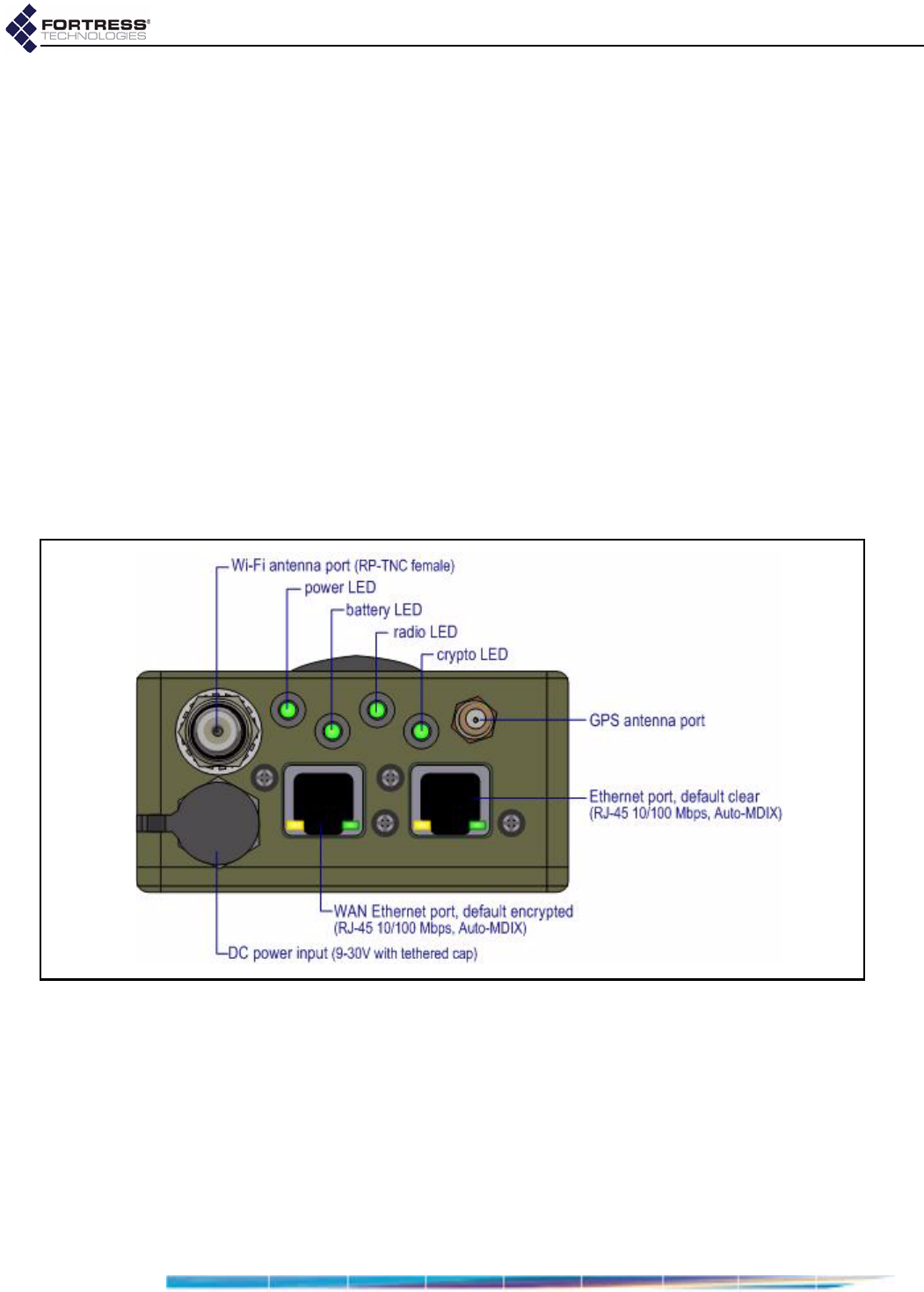
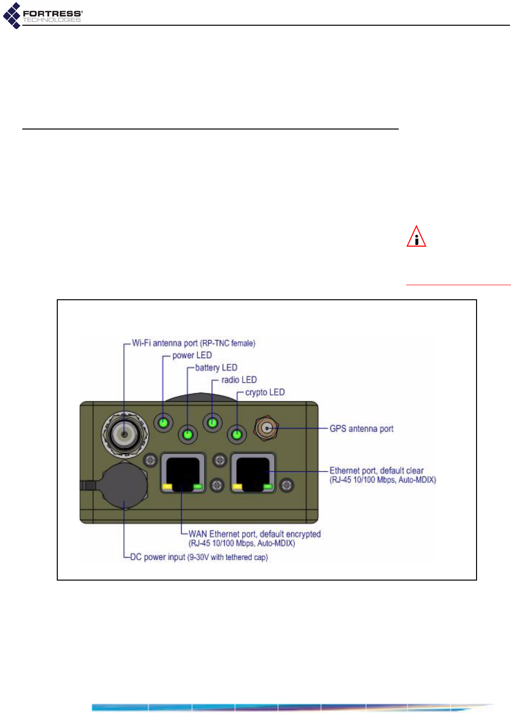
2.2.3 Port Locations
The ES210 Bridge’s power inlet and Ethernet and antenna
ports, along with the LED indicators, are located on the top
panel, shown below.
Figure 2.1. ES210 Bridge Port Locations
2.2.4 Deployment Options
The Bridge can be used, in either the 802.11a or the 802.11b/g
frequency band, as a wireless bridge or as a node in a mesh
network. It can simultaneously serve as a wireless LAN
(WLAN) access point (AP).
2.2.4.1 Mesh Bridging Deployment
Bridges configured to be able to connect to one another
automatically form mesh networks. One or more of the linked
D R A F T D O C U M E N T
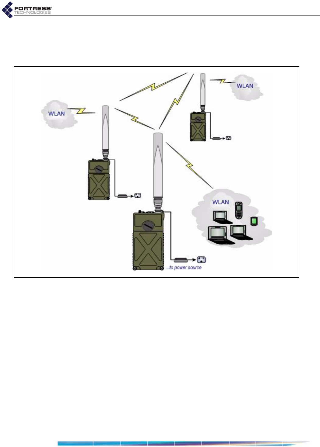
Fortress ES210: Installation
9
Bridges (or network nodes) can additionally securely connect
the network to a LAN and/or provide wireless LAN (WLAN)
connectivity for compatibly configured wireless devices within
range, as shown in Figure 2.2.
Figure 2.2. Example Mesh Network Deployment
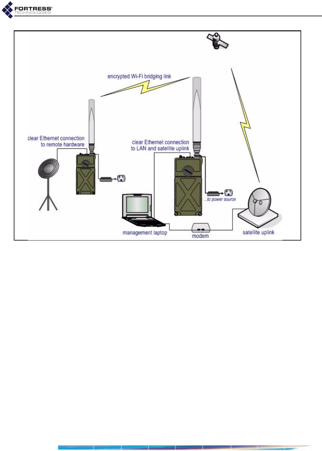
2.2.4.2 Point-to-Point LAN Bridging Deployment
The Bridge can be deployed as a conventional wireless Bridge
to connect two separately located LANs (local area networks),
for example, or to link remotely located hardware to the local
network for system management and data upload, as shown in
Figure 2.3).
D R A F T D O C U M E N T
Fortress ES210: Installation
10
Figure 2.3. Example Wireless Point-to-Point Bridging Deployment
2.3 Installation
The operational details of the various deployments into which
the Bridge can be installed are highly configurable.
The preconfiguration steps included in these installation
instructions establish basic connectivity and security settings,
changing as few settings from their factory defaults as
possible. Consult Chapter 3 for complete configuration
information.
Bridges that will be used outdoors for or in a difficult to reach
location must be configured in advance of their deployment.
2.3.1 Connecting the Bridge for Preconfiguration
1Position the Bridge so that it operates only within its safe
temperature range (14º–140º F/–10º–60º C).
2Connect the Bridge’s Ethernet port to a computer or switch
on the wired LAN.
3Connect the Bridge’s DC Power input to the standard AC/DC
power supply that shipped with the Bridge
4Connect the Bridge’s power supply to a properly rated AC
power outlet.
D R A F T D O C U M E N T
Fortress ES210: Installation
11
2.3.2 Preconfiguring the Bridge
The computer through which you configure the Bridge must
have a direct (non-routed) connection to the Bridge’s clear
zone and an IP address in the same subnet (192.168.254.0) as
the Bridge’s default IP address.
1Power the Bridge on by depressing the lower Power On
button on the left side of the chassis.
2Open a browser application on a computer on your LAN
and, in the browser address field, enter the Bridge’s default
IP address: 192.168.254.254. (If prompted, click OK to
accept the security certificate.)
CAUTION:You
mustchangethe
AccessIDandsystem
passwordsinorderto
securethenetworkand
theBridge.
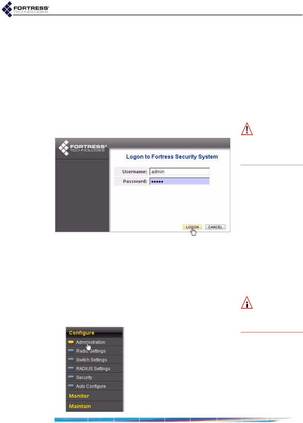
3Log on to the Bridge GUI, entering admin as both
Username and Password and then clicking LOGON.
4In the resulting Create a new password dialog, enter and
confirm a new admin account password—of at least 15
alphanumeric characters and/or symbols (excluding double
and single quotation marks)—and click SUBMIT.
5Log back on to the Bridge GUI, entering admin in
Username and the Password you created in Step 4 above,
and then clicking Logon.
NOTE:Youmust
scrollthroughthe
warrantyandlicensein
ordertoenabletheac‐
ceptancecheckbox.
6If you agree to the terms of the Product Warranty and
License Terms, click to place a check in the box beside I
have read and accept the terms above and then click
CONTINUE (or CANCEL the logon).
D R A F T D O C U M E N T
Fortress ES210: Installation
12
7Establish essential network settings through Configure ->
Administration -> Network Configuration:
Enter an IPv4 Address, IPv4 Subnet Mask and IPv4
Default Gateway for the Bridge.
Bridges connected as wireless bridges or mesh network
nodes must be configured with IP addresses in the same
subnet.
8Click APPLY in the upper right of the screen.
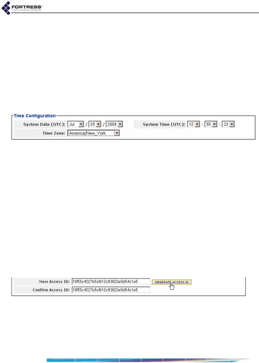
9Establish system time through Configure -> Administration
-> Time Configuration:
Use the dropdown menus to set the System Date,
System Clock and Time Zone to current values.
10 Click APPLY in the upper right of the screen.
11 Change the default passwords for the remaining two
preconfigured administrative accounts through Configure ->
Administration -> Administrator Settings:
Click GENERATE PASSWORD to automatically generate a
15-character password.
or Enter and re-enter a new password for the maintenance
logviewer accounts in New Password and Confirm
Password.
Record and secure the new passwords for future
reference; you cannot query system passwords after
they are established.
12 Click APPLY in the upper right of the screen.
13 Change the network Access ID through Configure ->
Security -> Security Settings:
Click GENERATE ACCESS ID to generate a 32-digit
hexadecimal Access ID.
or In the New Access ID field, enter a 32-digit hexadecimal
Access ID.
Record and secure the new Access ID for future
reference; you cannot query it after it has been
established.
D R A F T D O C U M E N T
Fortress ES210: Installation
13
Networked Bridges and Fortress Secure Clients connecting
to the Bridge-secured network must be configured to use
the same Access ID. (Consult the user guide for the Secure
Client for information on setting the Access ID on Client
devices.)
14 Click APPLY in the upper right of the screen.
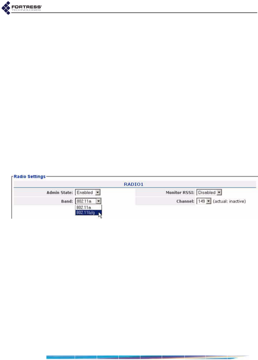
15 Enable and configure the radio through Configure -> Radio
Settings -> Radio Settings:
Select Enabled for the radio’s Admin State.
If the radio will provide only the bridging link in a point-
to-point or mesh network, leave the radio Band setting
at its default of 802.11a.
or
If the radio will serve as an WLAN AP (with or without
simultaneous network bridging), select 802.11b/g for the
radio’s Band.
Networked Bridges and wireless devices connecting to the
Bridge-secured network must be configured to use the
same radio frequency band and channel. (Consult a
wireless device’s user guidance for information on
configuring the device.)
16 Click APPLY in the upper right of the screen.
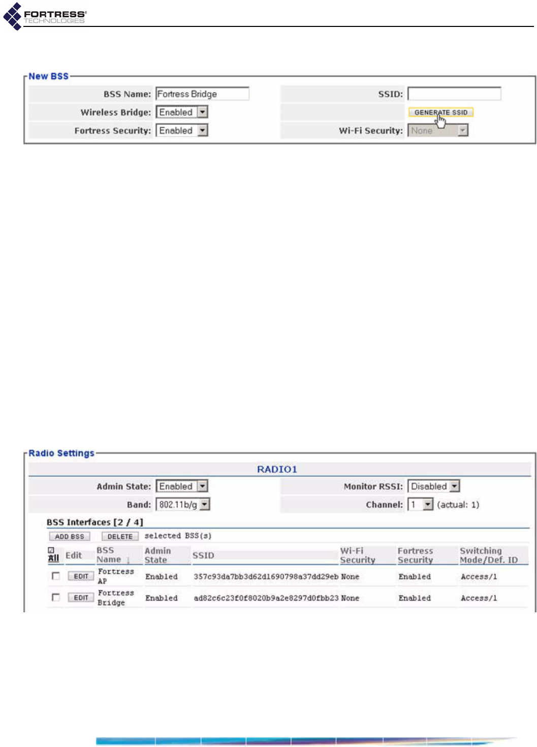
17 If you are not using the radio for bridging, skip to Step .
or
If you are using the radio for mesh network bridging, create
the bridging Basic Service Set through Configure -> Radio
Settings -> ADD BSS:
Enter a BSS Name.
Select Enabled for Wireless Bridge.
Click GENERATE SSID to automatically generate a 32-
character alphanumeric SSID.
or
D R A F T D O C U M E N T
Fortress ES210: Installation
14
Enter a 32-character alphanumeric SSID for the BSS.
Networked Bridges must be configured to use the same
SSID.
18 Click APPLY in the upper right of the screen.
19 If you are not using the radio as an AP, skip to Step 21.
or
If you are using the radio as a WLAN access point, create
the AP Basic Service Set through Configure -> Radio
Settings -> ADD BSS:
Enter a BSS Name.
Click GENERATE SSID to automatically generate a 32-
character alphanumeric SSID.
or Enter a 32-character alphanumeric SSID for the BSS.
Wireless devices connecting to the Bridge-secured network
must be configured to use the same SSID as the Bridge’s
AP BSS. (Consult a wireless device’s user guidance for
information on configuring the device.)
20 Click APPLY in the upper right of the screen.
Configured BSSs are displayed below the Radio Settings.
D R A F T D O C U M E N T
Fortress ES210: Installation
15
WARNING:Ifan
indoorBridgecon‐
nectstooutside‐mount‐
edantennas,failureto
providealowresistive
earthgroundcanresult
inmigrationofvoltage
fromlightningorline
surgesontothepre‐
miseswiring,whichcan
causeelectricshock
and/orfirewithinthe
buildingorstructure.
21 LOGOFF the Bridge GUI.
22 Power the Bridge down by depressing the Power Off button
on the right side of the chassis.
Alternatively, you can use the Bridge CLI to preconfigure the
Bridge. Chapter 5 describes the use of the Bridge CLI.
2.3.3 Connecting the Bridge for Deployment
Review the Radio Frequency Safety Requirements (Section
2.2.1) before installing or operating Bridge radios.
1Position the Bridge so that it operates only within its safe
temperature range (14º–140º F/–10º–60º C).
WARNING:To
complywithFCC
regulations,antennas
mustbeprofessionally
installedandtheinstall‐
erisresponsibleforen‐
suringcompliancewith
FCClimits.
2Connect the Bridge’s DC Power input to the standard AC/DC
power supply that shipped with the Bridge
3Connect the Bridge’s power supply to a properly rated AC
power outlet.
4If the Bridge will be used to secure connections to a wired
LAN, connect the clear Ethernet port to a computer or
switch on the wired LAN.
NOTE:Thirdpar‐
tyantennasare
subjecttolocalregulato‐
ryrequirements.For
outdoorinstallations,
theymustbewater‐
proof.
5If the Bridge’s internal radio will be used, connect the 5dBi
omnidirectional antenna that came with the Bridge to the
Wi-Fi antenna port.
D R A F T D O C U M E N T
Fortress ES210: LEDs and Pushbuttons
16
Chapter 3
LEDs and Pushbuttons
NOTE:
Thereare
noLEDindica‐
tionsinaBridgein
blackoutmode(referto
sections3.5.0.7and3.2.2.
3.1 Top-Panel Indicators
The ES210 Bridge’s top panel features four system LEDs
(Power, Battery, Radio, Crypto,) and a pair of Link and Activity
LEDs for each of the ES210’s two Ethernet ports.
Figure 3.1 Fortress Bridge LED Indicators
D R A F T D O C U M E N T

Fortress ES210: LEDs and Pushbuttons
17
3.1.1 System LEDs
Power
can exhibit:
solid green - Bridge is powered on.
off - Bridge is powered off.
slow-flash green - Bridge is booting.
fast-flash green - Bridge has a battery fault.
Battery
can exhibit:
The Battery LED is reserved for a future function on the
Bridge.
Radio
can exhibit:
solid green - Bridge’s RF Kill function is enabled.
intermittent green - Bridge’s 802.11a/b/g radio is passing
traffic.
Crypto
can exhibit:
solid green - Bridge has a FIPS failure.
fast-flash green - Bridge is passing cleartext traffic
(unencrypted data) in the encrypted zone.
3.1.2 Port LEDs
The ES210 Bridge’s top-panel Ethernet ports are equipped
with link/activity LEDs.
Lnk/Act
can exhibit:
solid green - A link has been established for the port.
intermittent green - Traffic is passing on the link.
off - The port is not connected.
color behavior Power
power Battery
battery Radio
802.11a/b/g Crypto
encryption
green
solid unit on
[reserved]
RF kill
activated FIPS failure
slow flash booting - -
fast flash battery fault - cleartext in
encrypted zone
intermittent - passing traffic -
off unit off radio off -
D R A F T D O C U M E N T
Fortress ES210: LEDs and Pushbuttons
18
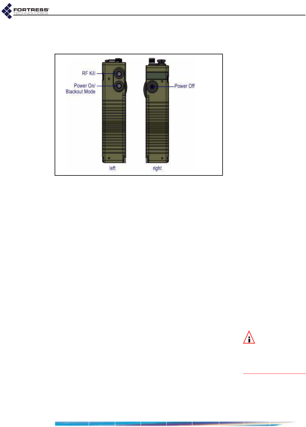
3.2 Pushbutton Operation
The ES210 Bridge is equipped with three pushbuttons.
Figure 3.2. ES210 pushbuttons
3.2.1 Powering the Bridge On and Off
The the lower button on the left side of the chassis powers the
ES210 Bridge on and the single button on the right side of the
chassis powers it off.
If the Bridge is off, press the Power On button to turn it on.
The Power LED will slow-flash green while the Bridge
boots, then light solid green for normal operation.
or
If the Bridge is on, press the Power Off button to turn it off.
The Power LED will go dark.
3.2.1.1 Pushbutton Rebooting
Reboot (hard boot) the ES210 by powering it off and back on
again (described above).
3.2.2 Pushbutton RF Kill and Blackout Mode
NOTE:Youcan
alsochangethe
Blackout ModeandRF Kill
settingsintheBridge
GUIorintheBridge
CLI.
The upper button on the left side of the chassis toggles the
Bridge’s RF Kill function.
The default RF Kill setting is Disabled, in which state the Bridge
receives and transmits radio frequency signals normally.
Enabling RF Kill tuns the Bridge’s internal radio off.
When the Bridge is powered on, the lower button on the left
side of the chassis turns the Bridge’s top-panel LEDs off and
on (Blackout Mode, Enabled/Disabled).
The default blackout mode setting is Disabled, in which state
the Bridge’s top-panel LEDs illuminate to indicate various
D R A F T D O C U M E N T

Fortress ES210: LEDs and Pushbuttons
19
conditions. (LED behaviors and their associated meanings are
covered in Section 3.1.) Enabling blackout mode turns all front-
panel LEDs off.
If a pushbutton configurable setting is Disabled, the actions
below will enable it. If the setting is Enabled, the same steps will
disable it.
1Press the button corresponding to the function you want to
toggle.
2Hold it down for five seconds.
3Release the button.
Both configuration changes persist over reboots and upgrades,
just as they do when changed through the Bridge GUI or CLI.
3.2.3 Pushbutton Restoring Defaults
To restore the Bridge’s configuration settings to their factory-
default values:
NOTE:Youcan
alsorestorethe
Bridge’sfactorydefault
settingsfromtheBridge
GUI(Section4.2.1.8)
andtheBridgeCLI.
1Simultaneously press the upper and lower buttons on the
left side of the Bridge chassis.
2Hold it them for at least ten seconds.
3Release both buttons.
After you have successfully initiated the restore operation, the
Bridge will reboot automatically.
After booting, the Bridge LEDs will resume normal operation
and all configuration settings, including the IP address of the
Bridge’s management interface will be at their factory-default
values.
D R A F T D O C U M E N T

Fortress ES210: Specifications
20
Chapter 4
Specifications
4.1 Hardware Specifications
4.1.1 Physical Specifications
4.1.2 Environmental Specifications
form factor: compact, wearable, mountable
dimensions: 7" H x 3.3" W x 1.7" D
(17.8 cm× 8.4cm×4.3cm, approx.)
weight: 2.1 lbs. (.95 kg, approx.)
power supply: 9-30 V DC input
connections:
two waterproof RJ-45 10/100 Mbps Ethernet ports with auto-MDIX
one cylindrical 3-pin serial port
one RP-TNC antenna port (female)
one SMA antenna port for GPS receiver (female, passive)
one weatherized 9-30V DC power input port with tethered cap
indicators: four front-panel system LEDs (Green/Amber):
Power, Battery, Radio, Crypto
two pairs integrated port Link and Activity LEDs
controls: three pushbuttons (usable wearing gloves)
maximum AC draw: 6 Watts
maximum heat dissipation: 20.5 BTU/hr
cooling: convection
operating temperature: 14º–158º F (-10º–60º C)
operating relative humidity
(non-condensing): 5%–95%
storage temperature: -4º–140º F (-20º–70º C)
D R A F T D O C U M E N T

Fortress ES210: Specifications
21
4.1.3 Compliance and Standards
The Fortress ES210 is certified by the Wi-Fi Alliance® for the
following standards:
4.2 DB9-to-3-pin Console Port Adapter
A DB9-to-3-pin cylindrical adapter is required in order to
connect the Bridge’s Console port to a DB9 terminal connection.
Table 4.1 shows the adapter pin-outs.
emissions: FCC Class A, part C;
MIL-STD 461F
immunity: MIL-STD 461F
vibration: MIL-STD 810F
IEEE: 802.11a/b/g/n
security: WPA™, WPA2™—Personal and Enterprise
EAP types: EAP-TLS, EAP-TTLS/MSCHAPv2,
PEAPv0/EAP-MSCHAPv2, PEAPv1/EAP-GTC,
EAP-SIM
Table 4.1. DB9-to-3-pin Cylindrical Adapter Pin-Outs
Description cylindrical pin DB9 pin standard color
Ground 1 5 red
Tx 2 2 black
Rx 3 3 white or green
D R A F T D O C U M E N T