Fuji Film 01000005 Flat Panel Sensor User Manual DR ID900PU Manual 2nd Ed f
Fuji Film Corporation Flat Panel Sensor DR ID900PU Manual 2nd Ed f
UserManual.wiki
>
Fuji Film
>
01000005 User Manual
(Short term Confidential)User Manual
Navigation menu
Upload a User Manual
Namespaces
Wiki Guide
HTML
PDF
Info
Views
User Manual
Discussion / Help
Navigation

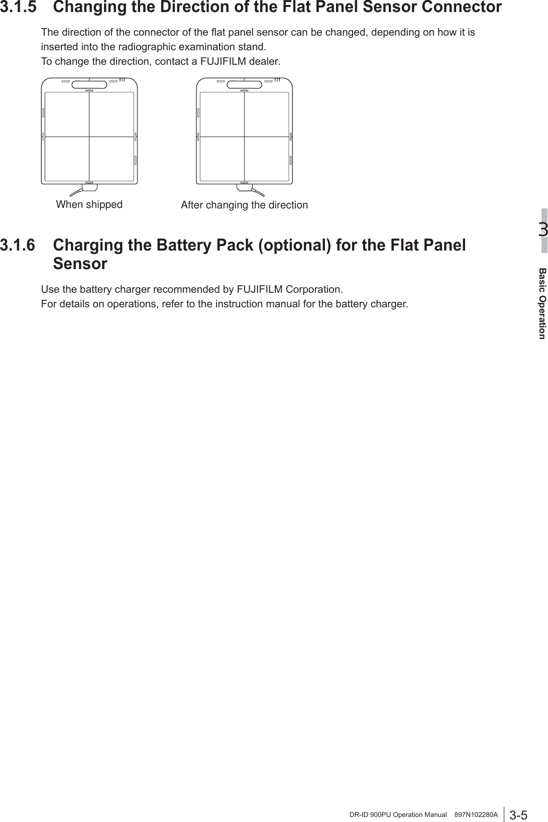
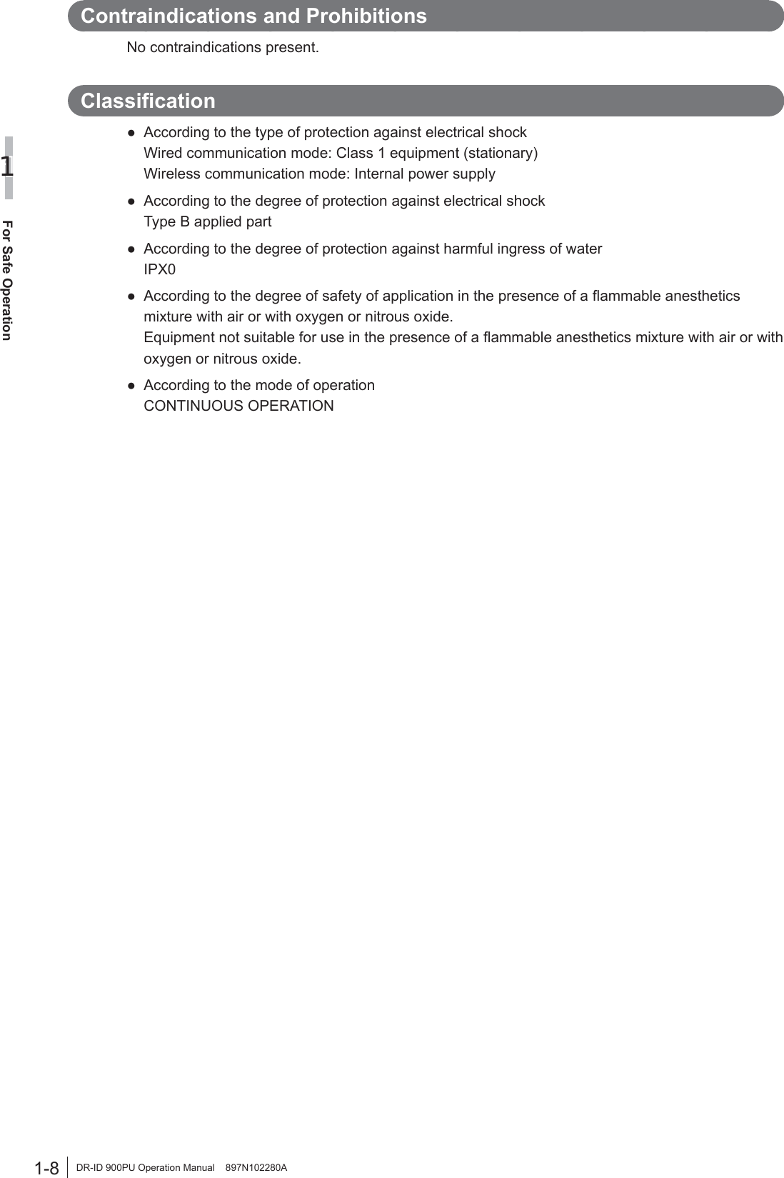
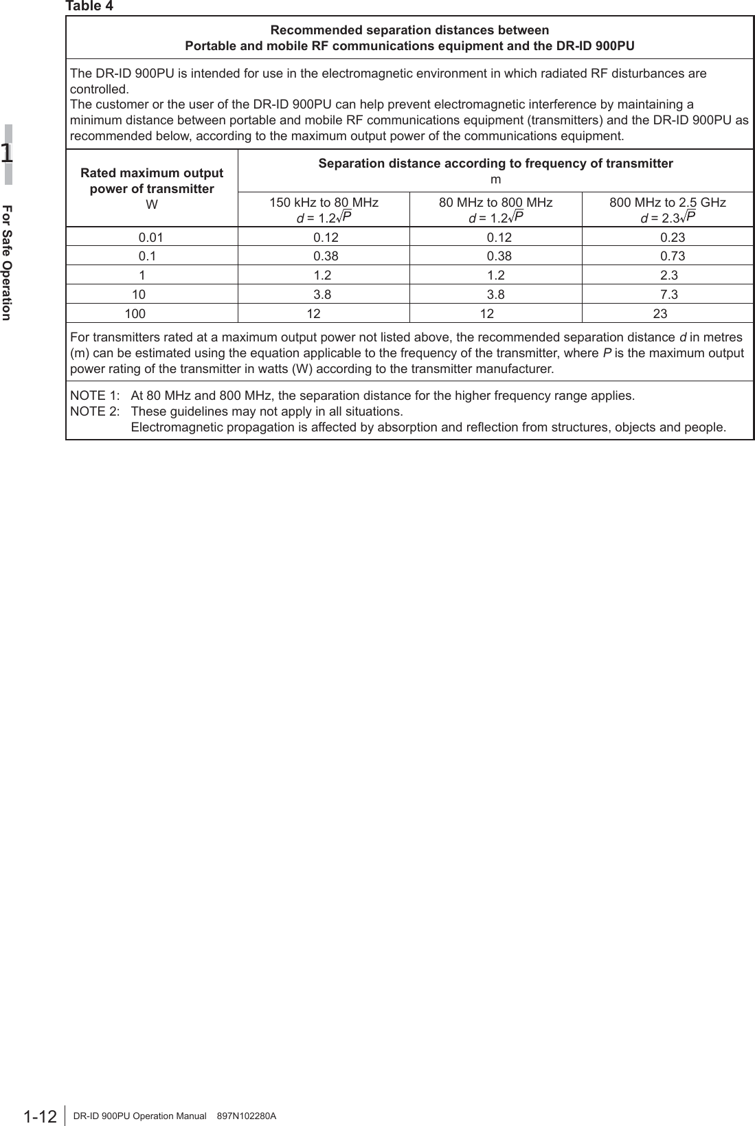
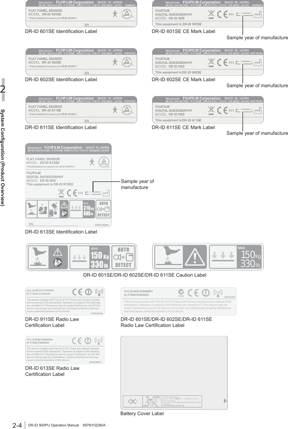
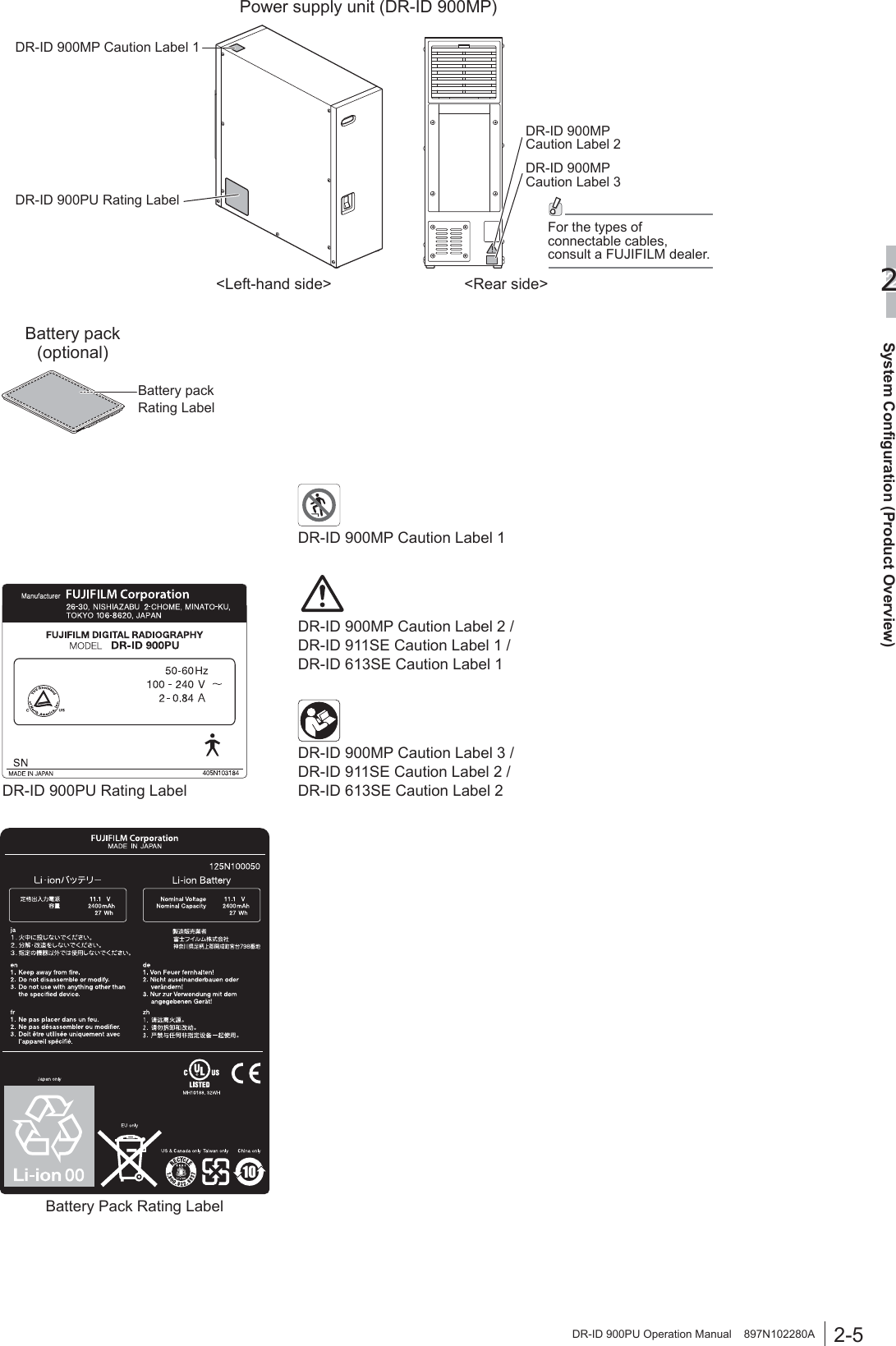
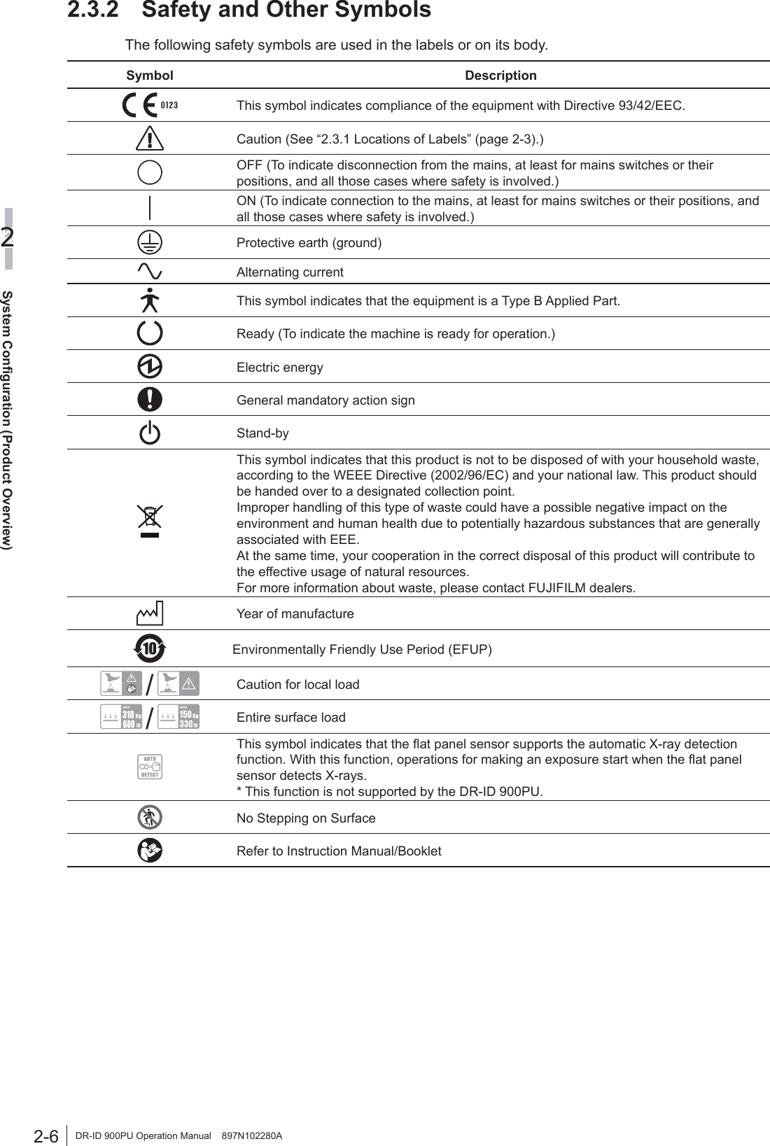
![iv DR-ID 900PU Operation Manual 897N102280AContentsIntroduction ...........................................................................................................................iiiChapter 1 For Safe Operation1.1 Safety ...................................................................................................................... 1-11.2 Electromagnetic Compatibility (EMC) ...................................................................... 1-91.2.1 DR-ID 900PU ...........................................................................................................1-9Chapter 2 System Configuration (Product Overview)2.1 DR-ID 900PU .......................................................................................................... 2-12.1.1 System Configuration ..............................................................................................2-12.2 Unit Names and the Functions ................................................................................ 2-22.3 Locations of Labels and Signs ................................................................................ 2-32.3.1 Locations of Labels ..................................................................................................2-32.3.2 Safety and Other Symbols .......................................................................................2-6Chapter 3 Basic Operation3.1 Preparing the Flat Panel Sensor ............................................................................. 3-13.1.1 Type of Flat Panel Sensor .......................................................................................3-13.1.2 Number of the Connectable Flat Panel Sensors .....................................................3-13.1.3 Connecting/Disconnecting the Flat Panel Sensor Connector ..................................3-23.1.4 Inserting/Removing the Flat Panel Sensor into/ from the Radiographic Examination Stand ..............................................................3-3 [1] In the case of the flat panel sensor DR-ID 911SE ..............................................3-3 [2] In the case of the flat panel sensors DR-ID 601SE/DR-ID 602SE/ DR-ID 611SE/DR-ID 613SE ...............................................................................3-33.1.5 Changing the Direction of the Flat Panel Sensor Connector ...................................3-53.1.6 Charging the Battery Pack (optional) for the Flat Panel Sensor ..............................3-53.1.7 Installing/Removing the Battery Pack (optional) for the Flat Panel Sensor .............3-63.2 Starting Up and Shutting Down the DR-ID 900PU .................................................. 3-73.2.1 Starting Up the DR-ID 900PU ..................................................................................3-73.2.2 Shutting Down the DR-ID 900PU ............................................................................3-7Chapter 4 Daily Inspection and Maintenance4.1 Daily User Inspection and Maintenance .................................................................. 4-14.1.1 Periodical Inspection ................................................................................................4-1Appendix A SpecificationsA.1 Specifications ..........................................................................................................A-1A.1.1 Reduced Equivalent (DR-ID 900) ........................................................................... A-1A.1.2 Power Supply Conditions ........................................................................................ A-1A.1.3 Environmental Conditions ....................................................................................... A-1A.1.4 Image performance ................................................................................................. A-1Appendix O Use of Optional ItemsO.1 Optional Items ....................................................................................................... O-1O.2 Using the Retaining Bracket for MP ....................................................................... O-2 Maintenance and Inspection](https://usermanual.wiki/Fuji-Film/01000005/User-Guide-2206425-Page-4.png)
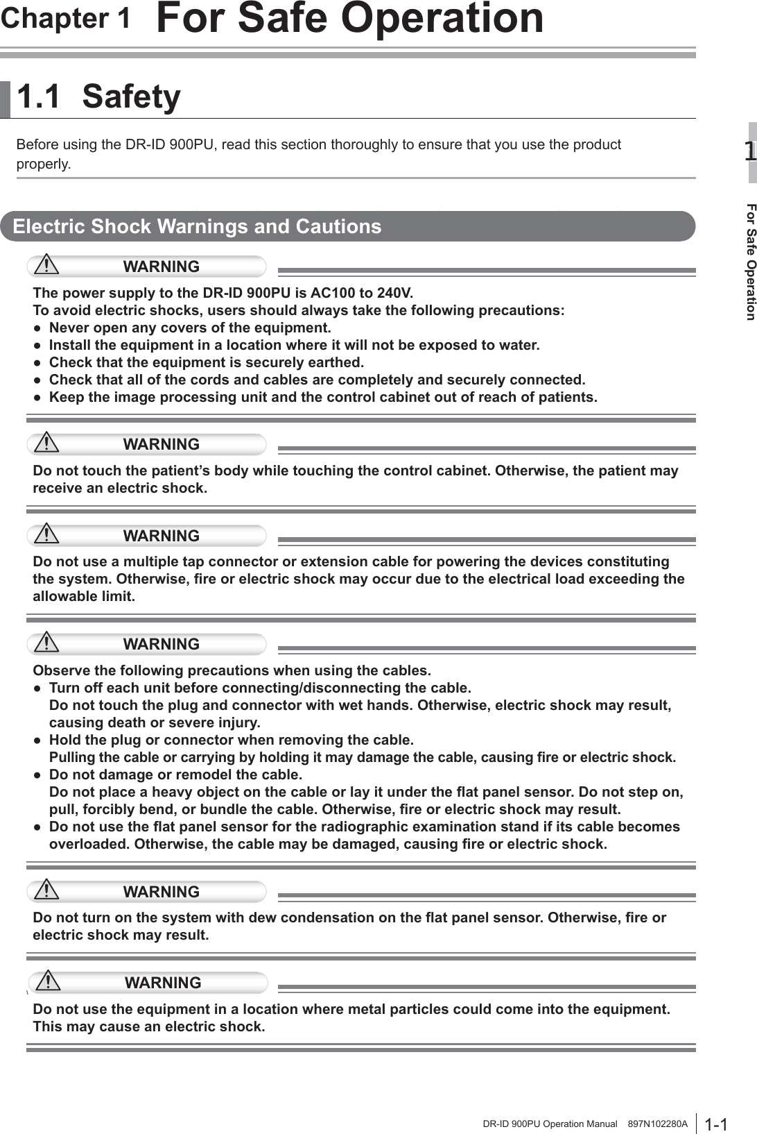
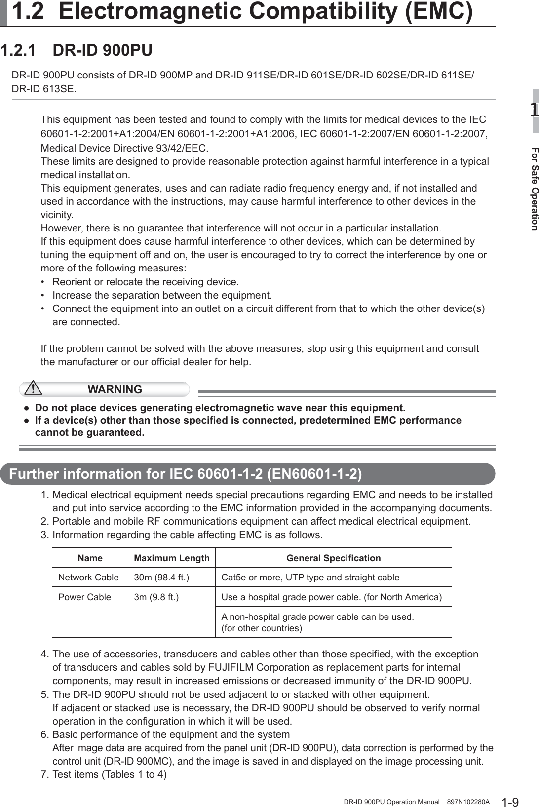
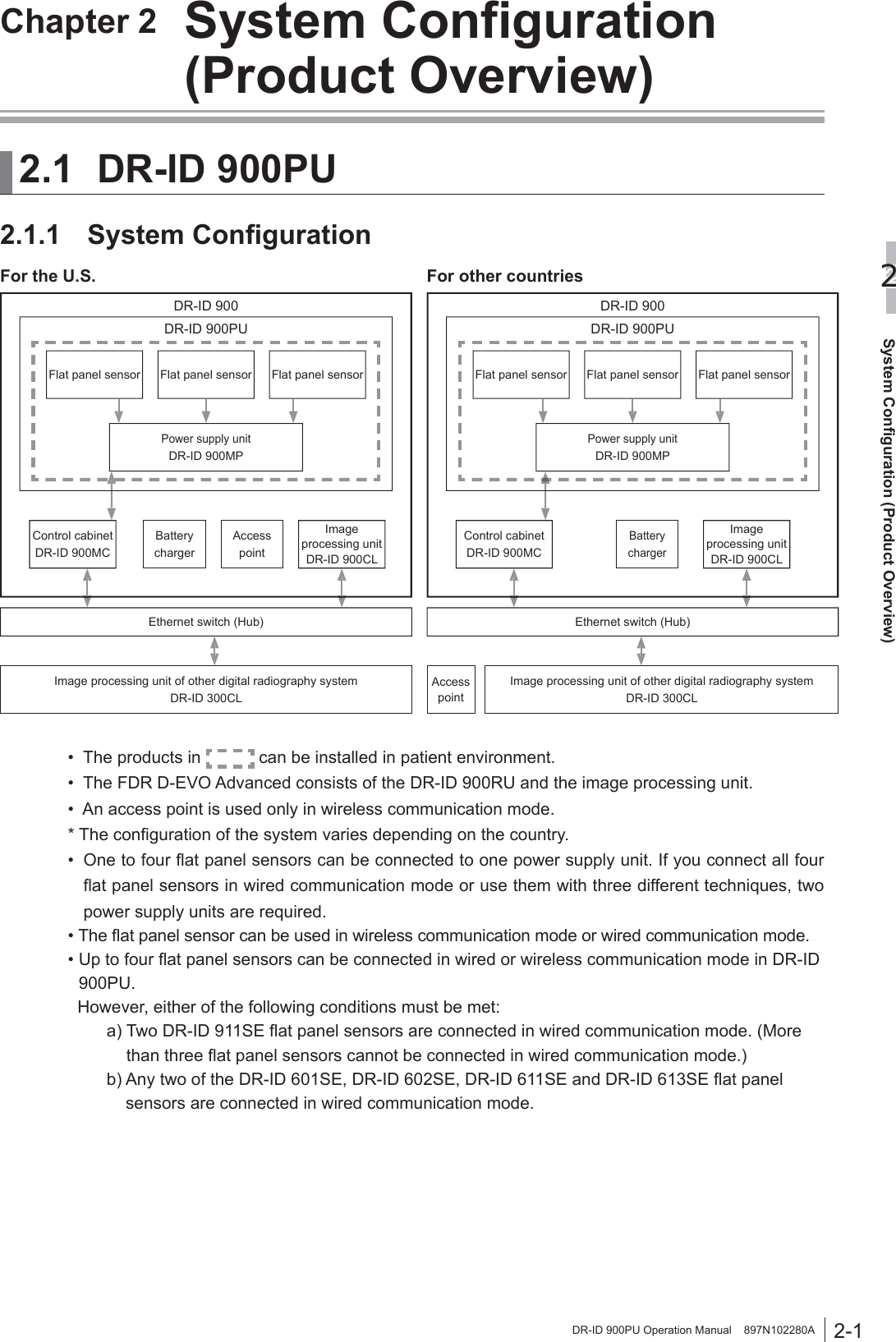
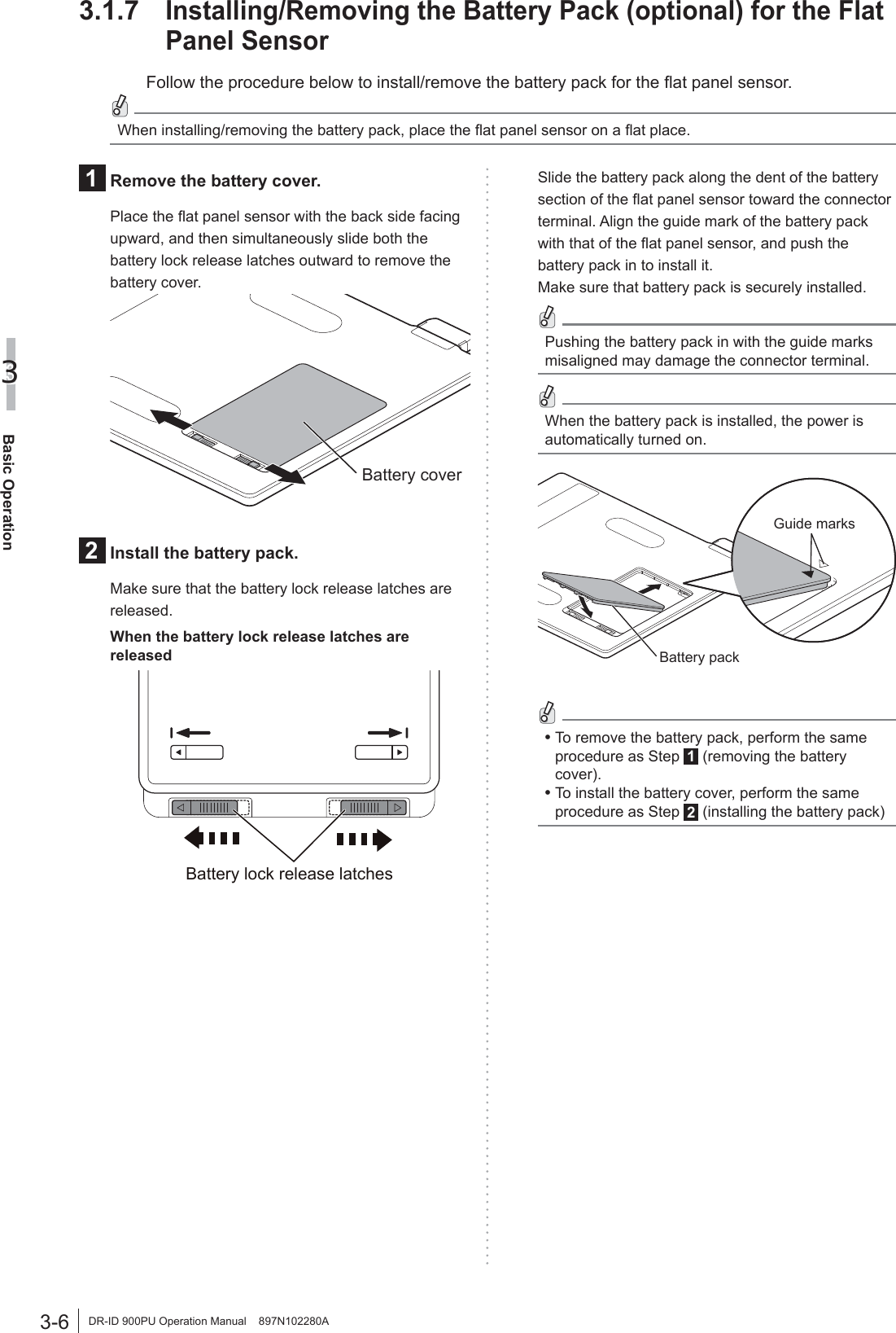
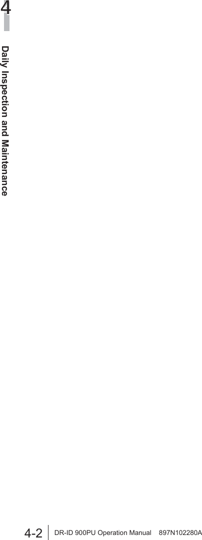
![3-1Basic Operation3DR-ID 900PU Operation Manual 897N102280AChapter 3 Basic Operation3.1 Preparing the Flat Panel SensorThis section describes how to prepare the flat panel sensor. 3.1.1 Type of Flat Panel SensorWireless communication mode or wired communication mode is available. When used in wireless communication mode, an access point*1, battery pack (optional) and battery charger (optional) are required.*1 In the countries other than the U.S., an access point is not included as a component of the system. For details including installation, consult our official dealer.• Product compliant with IEC60950, UL60950, PSE or JIS• Compliant with IEEE802.11n [W52] (in the 5.2GHz band) /36, 40, 44, 48ch• WLAN interface: 1000BASE-T/100BASE-TX (minimum requirements)• LAN interface: 1000BASE-T/100BASE-TX (minimum requirements)• Available OS: Linux• Compliant with UL• Compliant with FCC part15CAUTIONSUse only one access point. A communication error may occur if two units or more are used.3.1.2 Number of the Connectable Flat Panel SensorsTo enable the flat panel sensor, its ID needs to be registered in advance by a FUJIFILM dealer. Up to five flat panel sensors can be registered. Up to four flat panel sensors can be connected in wired or wireless communication mode in DR-ID 900PU. However, either of the following conditions must be met:a) Two DR-ID 911SE flat panel sensors are connected in wired communication mode. (More than three flat panel sensors cannot be connected in wired communication mode.)b) Any two of the DR-ID 601SE, DR-ID 602SE, DR-ID 611SE and DR-ID 613SE flat panel sensors are connected in wired communication mode.(Connection example)Image processing unitControl cabinet(DR-ID 900MC)Ethernet switch (Hub)Flat panel sensorFlat panel sensorFlat panel sensorFlat panel sensor Wired communication mode Wireless communication modePower supply unit (DR-ID 900MP)Power supply unit (DR-ID 900MP)Access pointWhen multiple flat panel sensors are connected, make sure that the READY lamp among the status lamps of the flat panel sensor to be used for an exposure is lit.](https://usermanual.wiki/Fuji-Film/01000005/User-Guide-2206425-Page-23.png)
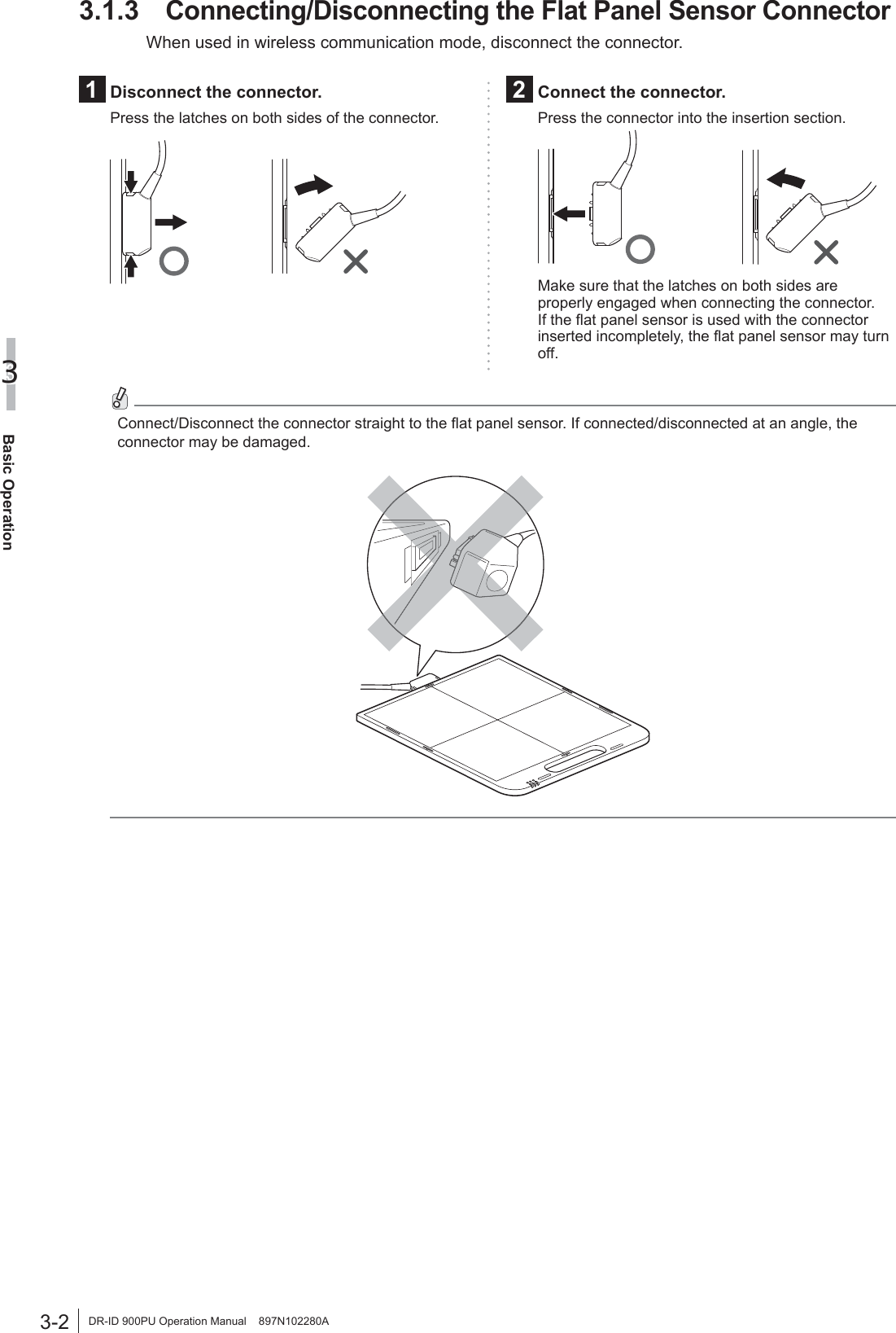
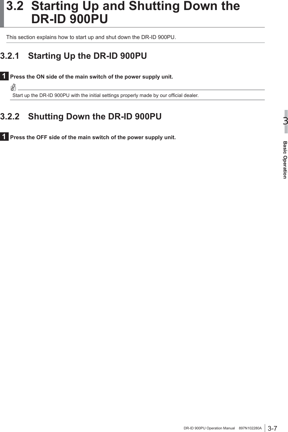
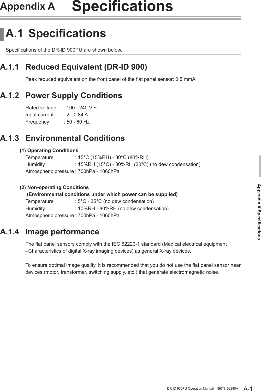
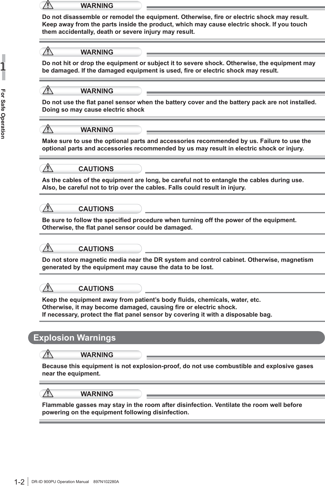
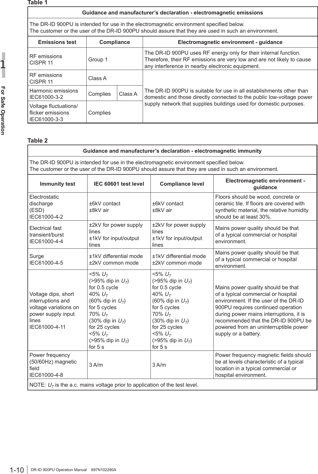
![3-3Basic Operation3DR-ID 900PU Operation Manual 897N102280A3.1.4 Inserting/Removing the Flat Panel Sensor into/from the Radiographic Examination Stand [1] In the case of the flat panel sensor DR-ID 911SEThe DR-ID 911SE cannot be mounted to any radiographic examination stand other than one specified by FUJIFILM Corporation. For details, refer to the operation manual of the radiographic examination stand. [2] In the case of the flat panel sensors DR-ID 601SE/ DR-ID 602SE/DR-ID 611SE/DR-ID 613SEFollow the procedure below to insert/remove the flat panel sensor into/from the radiographic examination stand. For details, see the Operation Manual for the radiographic examination standCAUTIONSFor the positioning at the time of inserting/removing the flat panel sensor, see the Operation Manual for the radiographic examination stand.CAUTIONSBe careful not to have your fingers caught when inserting/removing the flat panel sensor into/from the radiographic examination stand.[1] Upright type When inserting from the right-hand sideCAUTIONSWhen inserting the flat panel sensor into the radiographic examination stand, direct the exposure plane toward the X-ray tube.1 Pull out the tray.Tray2 Insert the flat panel sensor into the cassette receive while the connector directed to the upper right, and then move it downwards.ConnectorCassette receive3 Set the flat panel sensor to the upper part of the tray.4 Push the tray back into place after setting the flat panel sensor.When inserting the flat panel sensor from the left-hand side, direct the connector to the lower left.Connector5 Remove the flat panel sensor after use.Pull out the tray, push the cassette receive downwards, and then remove the flat panel sensor. Push the tray back into place.](https://usermanual.wiki/Fuji-Film/01000005/User-Guide-2206425-Page-25.png)
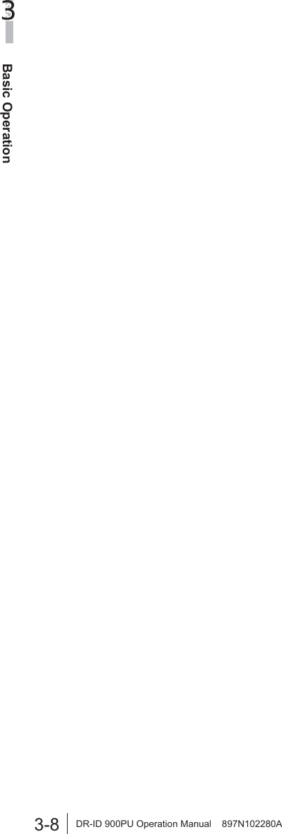
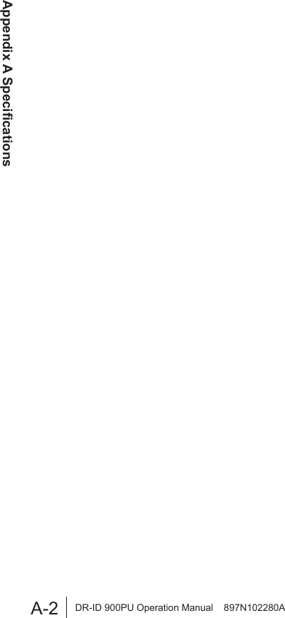
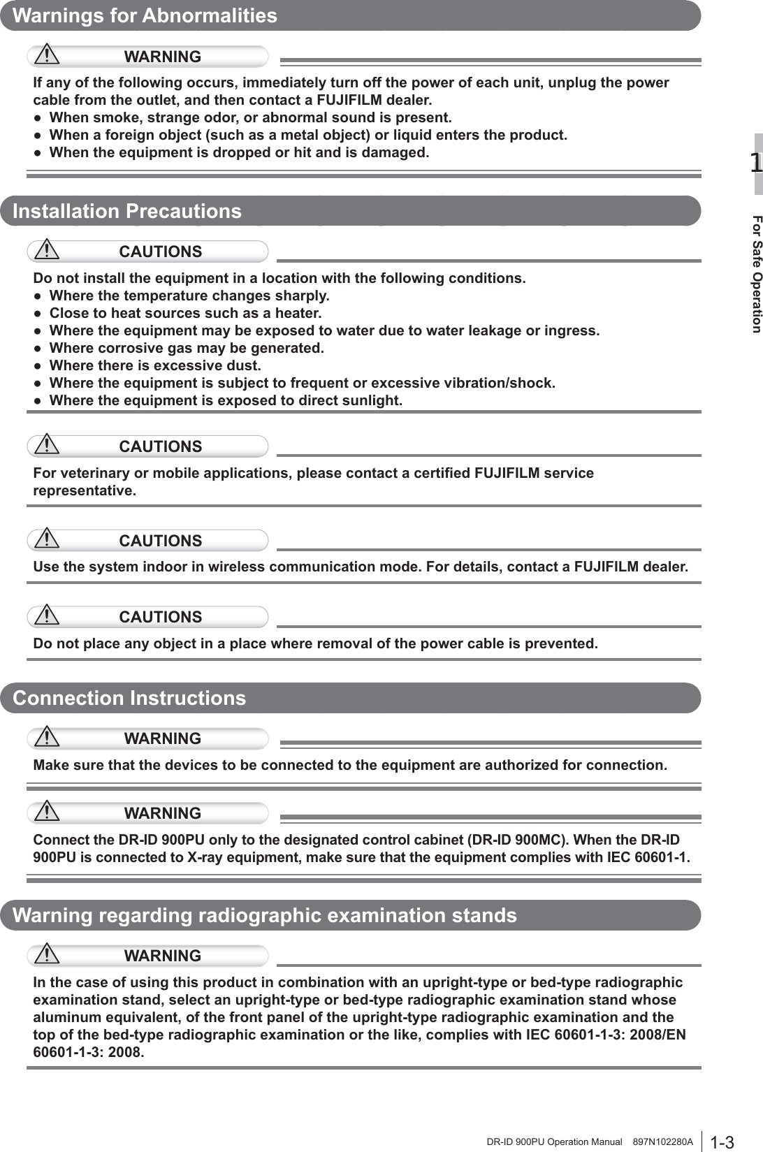
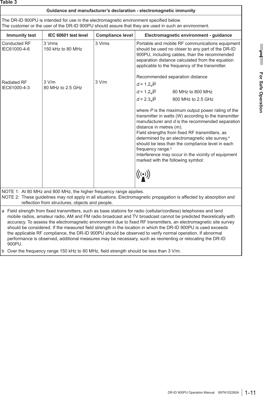
![3-4Basic Operation3DR-ID 900PU Operation Manual 897N102280A[2] Bed typeCAUTIONSWhen inserting the flat panel sensor to the radiographic examination stand, direct the exposure plane upwards.1 Pull out the tray by using the handle.Tray2 Pull the cassette stopper, and set the flat panel sensor so that its center mark is aligned with the center of the stopper.Position the connector of the flat panel sensor as shown in the figure below.Cassette stopperConnectorCenter markWhen setting the flat panel sensor horizontally, position the connector as shown in the figure below.Connector3 Push the tray back into place by using the handle after setting the flat panel sensor.4 Remove the flat panel sensor after use.Hold the handle and pull out the tray. Remove the flat panel sensor while pulling the cassette stopper, and then push the tray back into place.](https://usermanual.wiki/Fuji-Film/01000005/User-Guide-2206425-Page-26.png)