Fuji Film 01000005 Flat Panel Sensor User Manual DR ID900PU Manual 2nd Ed f
Fuji Film Corporation Flat Panel Sensor DR ID900PU Manual 2nd Ed f
(Short term Confidential)User Manual

897N102280A
This Operation Manual describes details on how to operate the DR-ID 900PU and
cautions to be observed when operating it.
Please read the Operation Manual thoroughly before actually operating the DR-ID
900PU along with “DR-ID 300CL Reference Guide” and other manuals for the related
products.
After reading this manual, store it nearby the DR-ID 900PU so that you can see it
whenever necessary.
DR-ID 900PU
Operation Manual
2nd Edition : July 2013
For Safe Operation
System
Configuration
(Product Overview)
Basic Operation
Daily Inspection and
Maintenance
Appendix
Maintenance and
Inspection

ii DR-ID 900PU Operation Manual 897N102280A

iii
DR-ID 900PU Operation Manual 897N102280A
Introduction
DR-ID 900PU is an X-ray equipment which acquires a general radiograph from the indirect-
conversion flat panel sensor.
DR-ID 900PU consists of DR-ID 900MP and DR-ID 911SE/DR-ID 601SE/DR-ID 602SE/DR-ID 611SE/
DR-ID 613SE.
DR-ID 911SE,
DR-ID 601SE, DR-ID 602SE, DR-ID 611SE and
DR-ID 613SE
:Wireless
communication mode or wired communication mode is available. When used in wireless
communication mode, an access point*1, battery pack (optional) and battery charger (optional) are
required.
*1 In the countries other than the U.S., an access point is not included as a component of the
system. For details including installation, consult our official dealer.
Each flat panel sensor complies with IEC 62220-1 (MEDICAL ELECTRICAL EQUIPMENT -
CHARACTERISTICS OF DIGITAL X-RAY IMAGING DEVICES - ) as a general X-ray radiography
equipment.
The detector of flat panel sensors features 150 micron pixel pitch, a wide 16-bit dynamic range and
exposure times up to 3.8 seconds.
This Operation Manual includes descriptions of matters necessary when using the DR-ID 900PU
such as the equipment overview, operation procedures and precautions to observe, as well as daily
inspections and maintenance.
Accompanying documents were originally drafted in the English language.
Installation may only be conducted by authorized service personal.
CAUTIONS
1. No part or all of this manual may be reproduced in any form without prior permission.
2. The information contained in this manual may be subject to change without prior notice.
3. FUJIFILM Corporation shall not be liable for malfunctions and damages resulting from
installation, relocation, remodeling, maintenance, and repair performed by other than dealers
specified by FUJIFILM Corporation.
4.
FUJIFILM Corporation shall not be liable for malfunctions and damages of FUJIFILM Corporation
products due to products of other manufacturers not supplied by FUJIFILM Corporation.
5.
FUJIFILM Corporation shall not be liable for malfunctions and damages resulting from remodeling,
maintenance, and repair using repair parts other than those specified by FUJIFILM Corporation.
6. FUJIFILM Corporation shall not be liable for malfunctions and damages resulting from
negligence of precautions and operating methods contained in this manual.
7. FUJIFILM Corporation shall not be liable for malfunctions and damages resulting from use
under environment conditions outside the range of using conditions for this product such as
power supply, installation environment, etc. contained in this manual.
8. FUJIFILM Corporation shall not be liable for malfunctions and damages resulting from
natural disasters such as fires, earthquakes, floods, lightning, etc.
This system is classified as a medical device under EC Directive 93/42/EEC.
Process waste correctly, as stipulated by local law or any regulations that apply.
Caution : Rx Only in the United States (Federal law restricts this device to sale by or on the order
of a physician.)
Open-Source Software Used in This Product
This product uses third party’s software that is made available as open source software or free software.
For information on open source software used in this product, please see the attached CD. Source
codes for certain type of open source software used in this product are available at delivery cost.
If you would like to receive such source codes, please contact FUJIFILM dealer or the service
representatives at the agency from which you purchased this product. (Please be noted that any inquiries
concerning the contents of source codes should be directed to original licensers of open source software.)
Note : FUJIFILM has successfully performed verification and validation testing on all third party
software and has confirmed its suitability to be used in this system.
Trademarks
All company names and product names described in this manual are the trademarks or registered
trademarks of FUJIFILM Corporation or their respective holders.
Windows is the registered trademark of US Microsoft Corporation in the U.S.A. and other countries.
Copyright © 2013 FUJIFILM Corporation. All rights reserved.

iv DR-ID 900PU Operation Manual 897N102280A
Contents
Introduction ...........................................................................................................................iii
Chapter 1 For Safe Operation
1.1 Safety ...................................................................................................................... 1-1
1.2 Electromagnetic Compatibility (EMC) ...................................................................... 1-9
1.2.1 DR-ID 900PU ...........................................................................................................1-9
Chapter 2 System Configuration (Product Overview)
2.1 DR-ID 900PU .......................................................................................................... 2-1
2.1.1 System Configuration ..............................................................................................2-1
2.2 Unit Names and the Functions ................................................................................ 2-2
2.3 Locations of Labels and Signs ................................................................................ 2-3
2.3.1 Locations of Labels ..................................................................................................2-3
2.3.2 Safety and Other Symbols .......................................................................................2-6
Chapter 3 Basic Operation
3.1 Preparing the Flat Panel Sensor ............................................................................. 3-1
3.1.1 Type of Flat Panel Sensor .......................................................................................3-1
3.1.2 Number of the Connectable Flat Panel Sensors .....................................................3-1
3.1.3 Connecting/Disconnecting the Flat Panel Sensor Connector ..................................3-2
3.1.4 Inserting/Removing the Flat Panel Sensor into/
from the Radiographic Examination Stand ..............................................................3-3
[1] In the case of the flat panel sensor DR-ID 911SE ..............................................3-3
[2] In the case of the flat panel sensors DR-ID 601SE/DR-ID 602SE/
DR-ID 611SE/DR-ID 613SE ...............................................................................3-3
3.1.5 Changing the Direction of the Flat Panel Sensor Connector ...................................3-5
3.1.6 Charging the Battery Pack (optional) for the Flat Panel Sensor ..............................3-5
3.1.7 Installing/Removing the Battery Pack (optional) for the Flat Panel Sensor .............3-6
3.2 Starting Up and Shutting Down the DR-ID 900PU .................................................. 3-7
3.2.1 Starting Up the DR-ID 900PU ..................................................................................3-7
3.2.2 Shutting Down the DR-ID 900PU ............................................................................3-7
Chapter 4 Daily Inspection and Maintenance
4.1 Daily User Inspection and Maintenance .................................................................. 4-1
4.1.1 Periodical Inspection ................................................................................................4-1
Appendix A Specifications
A.1 Specifications ..........................................................................................................A-1
A.1.1 Reduced Equivalent (DR-ID 900) ........................................................................... A-1
A.1.2 Power Supply Conditions ........................................................................................ A-1
A.1.3 Environmental Conditions ....................................................................................... A-1
A.1.4 Image performance ................................................................................................. A-1
Appendix O Use of Optional Items
O.1 Optional Items ....................................................................................................... O-1
O.2 Using the Retaining Bracket for MP ....................................................................... O-2
Maintenance and Inspection
1-1
For Safe Operation
1
DR-ID 900PU Operation Manual 897N102280A
Chapter 1 For Safe Operation
1.1 Safety
Before using the DR-ID 900PU, read this section thoroughly to ensure that you use the product
properly.
Electric Shock Warnings and Cautions
WARNING
The power supply to the DR-ID 900PU is AC100 to 240V.
To avoid electric shocks, users should always take the following precautions:
● Never open any covers of the equipment.
● Install the equipment in a location where it will not be exposed to water.
● Check that the equipment is securely earthed.
● Check that all of the cords and cables are completely and securely connected.
● Keep the image processing unit and the control cabinet out of reach of patients.
WARNING
Do not touch the patient’s body while touching the control cabinet. Otherwise, the patient may
receive an electric shock.
WARNING
Do not use a multiple tap connector or extension cable for powering the devices constituting
the system. Otherwise, fire or electric shock may occur due to the electrical load exceeding the
allowable limit.
WARNING
Observe the following precautions when using the cables.
● Turn off each unit before connecting/disconnecting the cable.
Do not touch the plug and connector with wet hands. Otherwise, electric shock may result,
causing death or severe injury.
● Hold the plug or connector when removing the cable.
Pulling the cable or carrying by holding it may damage the cable, causing fire or electric shock.
● Do not damage or remodel the cable.
Do not place a heavy object on the cable or lay it under the flat panel sensor. Do not step on,
pull, forcibly bend, or bundle the cable. Otherwise, fire or electric shock may result.
● Do not use the flat panel sensor for the radiographic examination stand if its cable becomes
overloaded. Otherwise, the cable may be damaged, causing fire or electric shock.
WARNING
Do not turn on the system with dew condensation on the flat panel sensor. Otherwise, fire or
electric shock may result.
\WARNING
Do not use the equipment in a location where metal particles could come into the equipment.
This may cause an electric shock.
1-2
For Safe Operation
1
DR-ID 900PU Operation Manual 897N102280A
WARNING
Do not disassemble or remodel the equipment. Otherwise, fire or electric shock may result.
Keep away from the parts inside the product, which may cause electric shock. If you touch
them accidentally, death or severe injury may result.
WARNING
Do not hit or drop the equipment or subject it to severe shock. Otherwise, the equipment may
be damaged. If the damaged equipment is used, fire or electric shock may result.
WARNING
Do not use the flat panel sensor when the battery cover and the battery pack are not installed.
Doing so may cause electric shock
WARNING
Make sure to use the optional parts and accessories recommended by us. Failure to use the
optional parts and accessories recommended by us may result in electric shock or injury.
CAUTIONS
As the cables of the equipment are long, be careful not to entangle the cables during use.
Also, be careful not to trip over the cables. Falls could result in injury.
CAUTIONS
Be sure to follow the specified procedure when turning off the power of the equipment.
Otherwise, the flat panel sensor could be damaged.
CAUTIONS
Do not store magnetic media near the DR system and control cabinet. Otherwise, magnetism
generated by the equipment may cause the data to be lost.
CAUTIONS
Keep the equipment away from patient’s body fluids, chemicals, water, etc.
Otherwise, it may become damaged, causing fire or electric shock.
If necessary, protect the flat panel sensor by covering it with a disposable bag.
Explosion Warnings
WARNING
Because this equipment is not explosion-proof, do not use combustible and explosive gases
near the equipment.
WARNING
Flammable gasses may stay in the room after disinfection. Ventilate the room well before
powering on the equipment following disinfection.
1-3
For Safe Operation
1
DR-ID 900PU Operation Manual 897N102280A
Warnings for Abnormalities
WARNING
If any of the following occurs, immediately turn off the power of each unit, unplug the power
cable from the outlet, and then contact a FUJIFILM dealer.
● When smoke, strange odor, or abnormal sound is present.
● When a foreign object (such as a metal object) or liquid enters the product.
● When the equipment is dropped or hit and is damaged.
Installation Precautions
CAUTIONS
Do not install the equipment in a location with the following conditions.
● Where the temperature changes sharply.
● Close to heat sources such as a heater.
● Where the equipment may be exposed to water due to water leakage or ingress.
● Where corrosive gas may be generated.
● Where there is excessive dust.
● Where the equipment is subject to frequent or excessive vibration/shock.
● Where the equipment is exposed to direct sunlight.
CAUTIONS
For veterinary or mobile applications, please contact a certified FUJIFILM service
representative.
CAUTIONS
Use the system indoor in wireless communication mode. For details, contact a FUJIFILM dealer.
CAUTIONS
Do not place any object in a place where removal of the power cable is prevented.
Connection Instructions
WARNING
Make sure that the devices to be connected to the equipment are authorized for connection.
WARNING
Connect the DR-ID 900PU only to the designated control cabinet (DR-ID 900MC). When the DR-ID
900PU is connected to X-ray equipment, make sure that the equipment complies with IEC 60601-1.
Warning regarding radiographic examination stands
WARNING
In the case of using this product in combination with an upright-type or bed-type radiographic
examination stand, select an upright-type or bed-type radiographic examination stand whose
aluminum equivalent, of the front panel of the upright-type radiographic examination and the
top of the bed-type radiographic examination or the like, complies with IEC 60601-1-3: 2008/EN
60601-1-3: 2008.
1-4
For Safe Operation
1
DR-ID 900PU Operation Manual 897N102280A
Precautions on External Network Connection
CAUTIONS
When a setting of the network to which the equipment is connected has been changed,
check that the change does not affect the system operation and take measures if
necessary.
The setting change may include the following:
● Change of connection destination
● Addition of devices
● Removal of devices
● Update of devices
● Upgrade of devices
Software Precautions
CAUTIONS
Connect to the Ethernet Network of 1000BASE-T, 100BASE-TX, or 10BASE-T prescribed in the
IEEE standard 802.3.
Do not connect telephone lines to LAN connector. Only UTP-type straight LAN cables of 4-pair
Category 5 cable (CAT 5E) or higher are appropriate for connection to this connector.
CAUTIONS
After connecting this system to the network with other systems,confirm that the other systems
are not affected. If they are affected, take countermeasures such as network separation.
System Isolation Instructions
WARNING
To ensure complete system isolation, never install any unauthorized accessories or other such
items.
When it is necessary to install authorized accessories or optional items, contact a FUJIFILM
dealer.
WARNING
Keep equipment other than those used for patients out of their reach to ensure appropriate
system isolation.
WARNING
Do not move the Console from where it is installed.
WARNING
In normal use, have a patient take a proper positioning for exposure. The operator should operate the
system in a place where safety from radiation is ensured. The operator should also make sure before
exposure that no one but the patient is in the exposure area and the operating area of the system.
1-5
For Safe Operation
1
DR-ID 900PU Operation Manual 897N102280A
Software Precautions
CAUTIONS
Do not install additional software to the system. Do not uninstall any of the software
preinstalled in the system.
The system is preinstalled with the appropriate software. If other software is installed or if the
existing software is uninstalled, various operational errors may result.
Various operational errors may result.
Disinfection Instructions
WARNING
Confirm that the respiratory density of disinfectant including solvent is under legal regulation.
Certain disinfectants may damage health. When using a disinfectant, follow instructions
supplied by the manufacturers.
WARNING
Ethanol for disinfection is recommended as the disinfectant. Carefully read the instructions
and cautions supplied with the disinfectant before use. Do not use the following when
disinfecting. Otherwise, the equipment may be damaged, and its quality, performance, and
safety cannot be guaranteed.
● Chloric disinfectant which is strongly corrosive to metals and rubber. parts.
● Disinfectant whose use on metals, plastics, and coating is forbidden according to the
instructions supplied with the disinfectant.
● Formalin gas and disinfectant sprays that may get inside the equipment.
● Ultraviolet sterilizers
CAUTIONS
Clean the sensor unit of the flat panel sensor with ethanol for disinfection, etc. for each patient
to prevent infection.
Precautions for Charging the Battery
CAUTIONS
● Use the battery charger recommended by FUJIFILM Corporation.
For details on operations, refer to the instruction manual for the battery charger.
● Do not charge the battery pack near fire or under strong sunshine. If the built-in protection
mechanisms are activated by a high temperature, the battery pack cannot be charged. Also,
if the built-in protection mechanisms are damaged, the battery pack may be charged with
extremely high current and voltage, and abnormal chemical reactions may occur inside the
battery pack, causing it to overheat, emit smoke, explode or ignite.
● Immediately stop charging the battery pack, if charging is not completed within the specified
time. Otherwise, the battery pack may overheat, emit smoke, explode or ignite.
● Do not use the flat panel sensor near the AC adapter.
● Do not use the broken battery charger.
Battery Pack (Optional) Precautions
WARNING
If this equipment is not in use for while, store it with the battery pack removed. Not removing
the battery pack may cause malfunction.

1-6
For Safe Operation
1
DR-ID 900PU Operation Manual 897N102280A
CAUTIONS
Be sure to observe the following cautions when using the battery pack (optional).
● Do not use the battery pack with any device other than those designated by FUJIFILM
Corporation.
● Charge the battery pack only with the designated battery charger. If the battery pack is
charged under the charging conditions (voltage, current and charging method) different
from those specified by FUJIFILM Corporation, the battery pack may emit smoke, ignite,
explode or leak fluid.
● When storing the battery pack (125N100050) for a long period, charge the battery fully,
remove it from the flat panel sensor and then store it in a cool and dark place. Recharge the
stored battery every six months or every year. Otherwise a decrease in battery capacity or
other problems may result.
● Do not leave the removed battery pack in a car or other place exposed to high temperature.
● Use and store the battery pack only in the environmental conditions specified by FUJIFILM
Corporation. If the battery pack is used or stored in a place where it is exposed to high
temperature, the battery pack may emit smoke, ignite, explode or leak fluid.
● When disposing of the battery pack, consult our official dealer.
● Do not disassemble or remodel the battery pack. The battery pack is equipped with built-in
safety and protection mechanisms. If they are damaged, the battery pack may overheat, emit
smoke, explode or ignite.
● Do not connect the positive (+) and negative (-) terminals of the battery pack using any
metal object, such as a wire. Do not carry or store the battery pack together with metal
objects such as necklaces or hairpins. Otherwise, the battery pack may short-circuit and
overcurrent may flow, causing the battery pack to overheat, emit smoke, explode or ignite.
Metal objects such as necklaces or hairpins may also become hot.
●
Do not throw the battery pack into fire or expose it to excessive heat. Otherwise, its insulator
may melt, its gas release vent or safety mechanisms may be damaged, and/or its electrolyte
may catch fire, causing the battery pack to overheat, emit smoke, explode or ignite.
● Do not use or leave the battery pack in a place where it is exposed to high temperature (80°C
or higher), such as fire or a heater. If the resin separator is damaged due to heat, the battery
pack may short-circuit, causing it to overheat, emit smoke, explode or ignite.
● Do not immerse the battery pack in water or seawater, and do not allow it to become wet.
If the built-in protection mechanisms are damaged, the battery pack may overheat, emit
smoke, explode or ignite.
● Do not pierce the battery pack with a nail, hit it with a hammer, or step on it. Otherwise, the
battery pack may be damaged or deformed and short-circuit, causing it to overheat, emit
smoke, explode or ignite.
● Do not subject the battery pack to strong impact or throw it. If the built-in protection
mechanisms are damaged, the battery pack may be charged with extremely high current and
voltage, and abnormal chemical reactions may occur inside the battery pack, causing it to
overheat, emit smoke, explode or ignite.
● Do not use an apparently damaged or deformed battery pack. Otherwise, the battery pack
may overheat, emit smoke, explode or ignite.
● Do not solder the battery pack directly. Otherwise, its insulator may melt, or its gas release
vent or safety mechanisms may be damaged, causing the battery pack to overheat, emit
smoke, explode or ignite.
● Do not reverse the positive (+) and negative (-) terminals of the battery pack. Otherwise,
the battery pack may be reverse-charged during charging. As a result, abnormal chemical
reactions may occur inside the battery pack, or extremely high current may flow during
discharging, causing it to overheat, emit smoke, explode or ignite.
● The battery pack has a predetermined polarity. If you cannot connect the battery pack to the
battery charger or other equipment, do not connect the battery pack forcefully. Make sure
that the terminals are correctly oriented. If the battery pack is connected in reverse, it will
be reverse-charged, and abnormal chemical reactions may occur inside the battery pack,
causing it to overheat, emit smoke, explode or ignite.
● Do not connect the battery pack to an electrical outlet or cigarette lighter socket in a car.
Overcurrent may flow to the battery pack due to high voltage applied, causing the battery
pack to overheat, emit smoke, explode or ignite.
● Do not use the battery pack for equipment other than those specified. Otherwise, the
guaranteed performance will be reduced and/or the service life will be shortened. Depending
on the equipment to which the battery pack is connected, extremely high current may flow,
1-7
For Safe Operation
1
DR-ID 900PU Operation Manual 897N102280A
causing the battery pack to be damaged, overheat, emit smoke, explode or ignite.
● If the electrolyte leaked from the battery pack enters the eyes, do not rub them. Wash the
eyes immediately with clean water such as tap water, and consult a doctor. Otherwise, eye
injury may result.
● Do not use the battery pack in combination with a primary battery such as a dry battery or
other battery of a different capacity, type and/or brand. Otherwise, the battery pack may
be overcharged during charging, and abnormal chemical reactions may occur inside the
battery pack, causing it to overheat, emit smoke, explode or ignite.
● Do not put the battery pack in a microwave oven or high-pressure container. Otherwise, the
battery pack may be rapidly heated or damaged, causing it to overheat, emit smoke, explode
or ignite.
● If the battery pack leaks or emits an unusual odor, remove it from fire immediately.
Otherwise, the leaked electrolyte may catch fire, causing the battery pack to overheat, emit
smoke, explode or ignite.
●
If you notice an unusual odor, heat, discoloration, deformation or any other abnormality during
use, charging or storage, remove the battery pack from the equipment or battery charger, and
stop using it. Otherwise, the battery pack may overheat, emit smoke, explode or ignite.
● Do not use the battery pack exposed to a strong magnetic field of an MRI system, etc.
● Do not use the battery pack immersed in liquid.
.
Other Warnings and Cautions
WARNING
No modification of this equipment is allowed.
CAUTIONS
Install the system in accordance with what is provided by IEC60601-1-1. Contact a FUJIFILM
dealer for installation and relocation (except the flat panel sensor) of the system.
CAUTIONS
Do not hit or drop the equipment. Otherwise, injury or damage to images, etc. may result.
CAUTIONS
Be sure to inspect the system periodically.
To assure optimum performance of the equipment, it is necessary to systematically perform
maintenance and inspection. For information on maintenance and inspection, contact a
FUJIFILM dealer.
CAUTIONS
The institution where the equipment is installed is responsible for its use and maintenance.
In addition, this equipment should not be used by persons other than doctors or suitably
trained staff.
CAUTIONS
Do not place the cable terminal on the floor.Doing so may cause infection.
Also, periodically clean the cable and the terminal.
CAUTIONS
The institution where the equipment is installed is responsible for its use and maintenance.
In addition, this equipment should not be used by persons other than doctors or suitably
trained staff.

1-8
For Safe Operation
1
DR-ID 900PU Operation Manual 897N102280A
Contraindications and Prohibitions
No contraindications present.
Classification
● According to the type of protection against electrical shock
Wired communication mode: Class 1 equipment (stationary)
Wireless communication mode: Internal power supply
● According to the degree of protection against electrical shock
Type B applied part
● According to the degree of protection against harmful ingress of water
IPX0
● According to the degree of safety of application in the presence of a flammable anesthetics
mixture with air or with oxygen or nitrous oxide.
Equipment not suitable for use in the presence of a flammable anesthetics mixture with air or with
oxygen or nitrous oxide.
● According to the mode of operation
CONTINUOUS OPERATION

1-9
For Safe Operation
1
DR-ID 900PU Operation Manual 897N102280A
1.2 Electromagnetic Compatibility (EMC)
1.2.1 DR-ID 900PU
DR-ID 900PU consists of DR-ID 900MP and DR-ID 911SE/DR-ID 601SE/DR-ID 602SE/DR-ID 611SE/
DR-ID 613SE.
This equipment has been tested and found to comply with the limits for medical devices to the IEC
60601-1-2:2001+A1:2004/EN 60601-1-2:2001+A1:2006, IEC 60601-1-2:2007/EN 60601-1-2:2007,
Medical Device Directive 93/42/EEC.
These limits are designed to provide reasonable protection against harmful interference in a typical
medical installation.
This equipment generates, uses and can radiate radio frequency energy and, if not installed and
used in accordance with the instructions, may cause harmful interference to other devices in the
vicinity.
However, there is no guarantee that interference will not occur in a particular installation.
If this equipment does cause harmful interference to other devices, which can be determined by
tuning the equipment off and on, the user is encouraged to try to correct the interference by one or
more of the following measures:
• Reorient or relocate the receiving device.
• Increase the separation between the equipment.
• Connect the equipment into an outlet on a circuit different from that to which the other device(s)
are connected.
If the problem cannot be solved with the above measures, stop using this equipment and consult
the manufacturer or our official dealer for help.
WARNING
● Do not place devices generating electromagnetic wave near this equipment.
● If a device(s) other than those specified is connected, predetermined EMC performance
cannot be guaranteed.
Further information for IEC 60601-1-2 (EN60601-1-2)
1. Medical electrical equipment needs special precautions regarding EMC and needs to be installed
and put into service according to the EMC information provided in the accompanying documents.
2. Portable and mobile RF communications equipment can affect medical electrical equipment.
3. Information regarding the cable affecting EMC is as follows.
Name Maximum Length General Specification
Network Cable 30m (98.4 ft.) Cat5e or more, UTP type and straight cable
Power Cable 3m (9.8 ft.) Use a hospital grade power cable. (for North America)
A non-hospital grade power cable can be used.
(for other countries)
4. The use of accessories, transducers and cables other than those specified, with the exception
of transducers and cables sold by FUJIFILM Corporation as replacement parts for internal
components, may result in increased emissions or decreased immunity of the DR-ID 900PU.
5. The DR-ID 900PU should not be used adjacent to or stacked with other equipment.
If adjacent or stacked use is necessary, the DR-ID 900PU should be observed to verify normal
operation in the configuration in which it will be used.
6. Basic performance of the equipment and the system
After image data are acquired from the panel unit (DR-ID 900PU), data correction is performed by the
control unit (DR-ID 900MC), and the image is saved in and displayed on the image processing unit.
7. Test items (Tables 1 to 4)
1-10
For Safe Operation
1
DR-ID 900PU Operation Manual 897N102280A
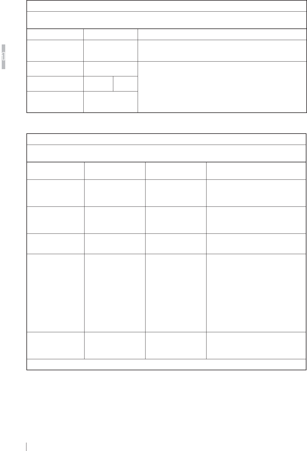
Table 1
Guidance and manufacturer’s declaration - electromagnetic emissions
The DR-ID 900PU is intended for use in the electromagnetic environment specified below.
The customer or the user of the DR-ID 900PU should assure that they are used in such an environment.
Emissions test Compliance Electromagnetic environment - guidance
RF emissions
CISPR 11 Group 1
The DR-ID 900PU uses RF energy only for their internal function.
Therefore, their RF emissions are very low and are not likely to cause
any interference in nearby electronic equipment.
RF emissions
CISPR 11 Class A
The DR-ID 900PU is suitable for use in all establishments other than
domestic and those directly connected to the public low-voltage power
supply network that supplies buildings used for domestic purposes.
Harmonic emissions
IEC61000-3-2 Complies Class A
Voltage fluctuations/
flicker emissions
IEC61000-3-3
Complies
Table 2
Guidance and manufacturer’s declaration - electromagnetic immunity
The DR-ID 900PU is intended for use in the electromagnetic environment specified below.
The customer or the user of the DR-ID 900PU should assure that they are used in such an environment.
Immunity test IEC 60601 test level Compliance level Electromagnetic environment -
guidance
Electrostatic
discharge
(ESD)
IEC61000-4-2
±6kV contact
±8kV air
±6kV contact
±8kV air
Floors should be wood, concrete or
ceramic tile. If floors are covered with
synthetic material, the relative humidity
should be at least 30%.
Electrical fast
transient/burst
IEC61000-4-4
±2kV for power supply
lines
±1kV for input/output
lines
±2kV for power supply
lines
±1kV for input/output
lines
Mains power quality should be that
of a typical commercial or hospital
environment.
Surge
IEC61000-4-5
±1kV differential mode
±2kV common mode
±1kV differential mode
±2kV common mode
Mains power quality should be that
of a typical commercial or hospital
environment.
Voltage dips, short
interruptions and
voltage variations on
power supply input
lines
IEC61000-4-11
<5% UT
(>95% dip in UT)
for 0.5 cycle
40% UT
(60% dip in UT)
for 5 cycles
70% UT
(30% dip in UT)
for 25 cycles
<5% UT
(>95% dip in UT)
for 5 s
<5% UT
(>95% dip in UT)
for 0.5 cycle
40% UT
(60% dip in UT)
for 5 cycles
70% UT
(30% dip in UT)
for 25 cycles
<5% UT
(>95% dip in UT)
for 5 s
Mains power quality should be that
of a typical commercial or hospital
environment. If the user of the DR-ID
900PU requires continued operation
during power mains interruptions, it is
recommended that the DR-ID 900PU be
powered from an uninterruptible power
supply or a battery.
Power frequency
(50/60Hz) magnetic
field
IEC61000-4-8
3 A/m 3 A/m
Power frequency magnetic fields should
be at levels characteristic of a typical
location in a typical commercial or
hospital environment.
NOTE: UT is the a.c. mains voltage prior to application of the test level.
1-11
For Safe Operation
1
DR-ID 900PU Operation Manual 897N102280A
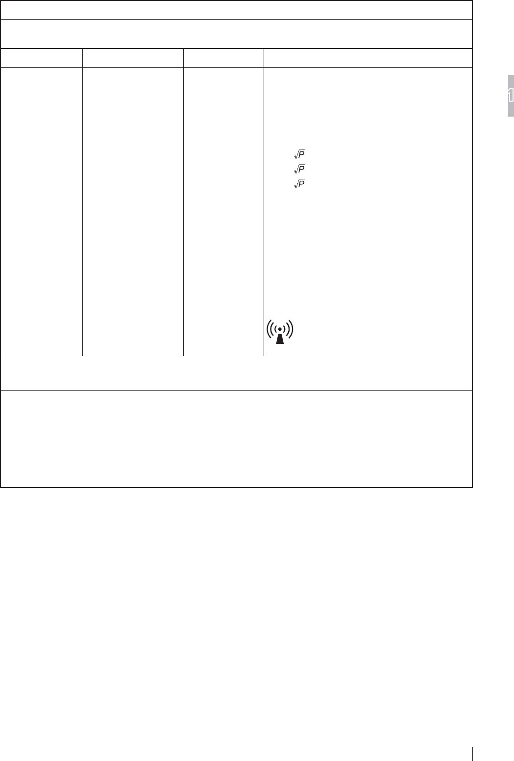
Table 3
Guidance and manufacturer’s declaration - electromagnetic immunity
The DR-ID 900PU is intended for use in the electromagnetic environment specified below.
The customer or the user of the DR-ID 900PU should assure that they are used in such an environment.
Immunity test IEC 60601 test level Compliance level Electromagnetic environment - guidance
Conducted RF
IEC61000-4-6
Radiated RF
IEC61000-4-3
3 Vrms
150 kHz to 80 MHz
3 V/m
80 MHz to 2.5 GHz
3 Vrms
3 V/m
Portable and mobile RF communications equipment
should be used no closer to any part of the DR-ID
900PU, including cables, than the recommended
separation distance calculated from the equation
applicable to the frequency of the transmitter.
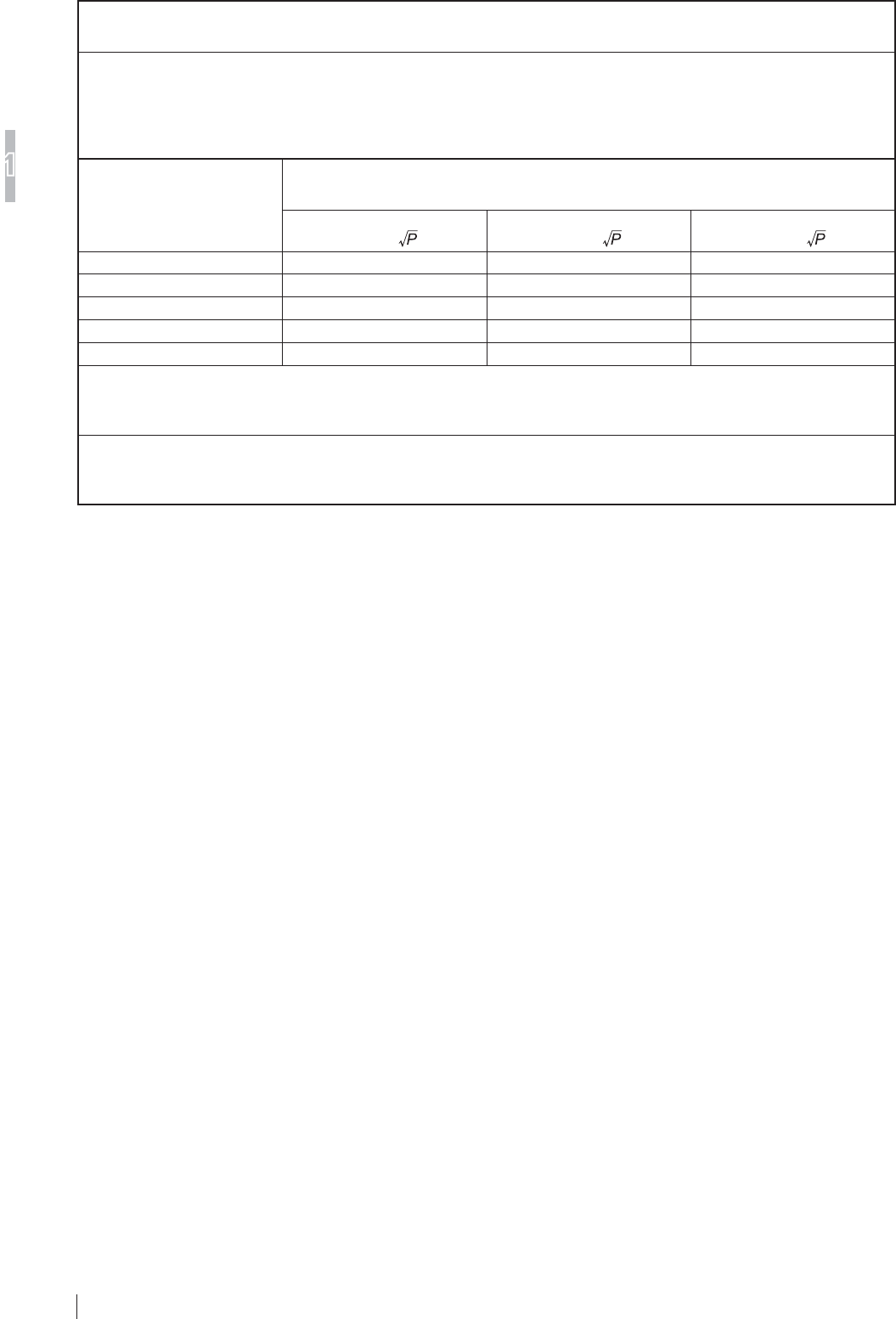
Recommended separation distance
d = 1.2
d = 1.2 80 MHz to 800 MHz
d = 2.3 800 MHz to 2.5 GHz
where
P
is the maximum output power rating of the
transmitter in watts (W) according to the transmitter
manufacturer and
d
is the recommended separation
distance in metres (m).
Field strengths from fixed RF transmitters, as
determined by an electromagnetic site survey,a
should be less than the compliance level in each
frequency range.b
Interference may occur in the vicinity of equipment
marked with the following symbol:
NOTE 1: At 80 MHz and 800 MHz, the higher frequency range applies.
NOTE 2: These guidelines may not apply in all situations. Electromagnetic propagation is affected by absorption and
reflection from structures, objects and people.
a Field strength from fixed transmitters, such as base stations for radio (cellular/cordless) telephones and land
mobile radios, amateur radio, AM and FM radio broadcast and TV broadcast cannot be predicted theoretically with
accuracy. To assess the electromagnetic environment due to fixed RF transmitters, an electromagnetic site survey
should be considered. If the measured field strength in the location in which the DR-ID 900PU is used exceeds
the applicable RF compliance, the DR-ID 900PU should be observed to verify normal operation. If abnormal
performance is observed, additional measures may be necessary, such as reorienting or relocating the DR-ID
900PU.
b Over the frequency range 150 kHz to 80 MHz, field strength should be less than 3 V/m.
1-12
For Safe Operation
1
DR-ID 900PU Operation Manual 897N102280A
Table 4
Recommended separation distances between
Portable and mobile RF communications equipment and the DR-ID 900PU
The DR-ID 900PU is intended for use in the electromagnetic environment in which radiated RF disturbances are
controlled.
The customer or the user of the DR-ID 900PU can help prevent electromagnetic interference by maintaining a
minimum distance between portable and mobile RF communications equipment (transmitters) and the DR-ID 900PU as
recommended below, according to the maximum output power of the communications equipment.
Rated maximum output
power of transmitter
W
Separation distance according to frequency of transmitter
m
150 kHz to 80 MHz
d = 1.2
80 MHz to 800 MHz
d = 1.2
800 MHz to 2.5 GHz
d = 2.3
0.01 0.12 0.12 0.23
0.1 0.38 0.38 0.73
1 1.2 1.2 2.3
10 3.8 3.8 7.3
100 12 12 23
For transmitters rated at a maximum output power not listed above, the recommended separation distance
d
in metres
(m) can be estimated using the equation applicable to the frequency of the transmitter, where
P
is the maximum output
power rating of the transmitter in watts (W) according to the transmitter manufacturer.
NOTE 1: At 80 MHz and 800 MHz, the separation distance for the higher frequency range applies.
NOTE 2: These guidelines may not apply in all situations.
Electromagnetic propagation is affected by absorption and reflection from structures, objects and people.
2-1
System Configuration (Product Overview)
2
DR-ID 900PU Operation Manual 897N102280A
Chapter 2 System Configuration
(Product Overview)
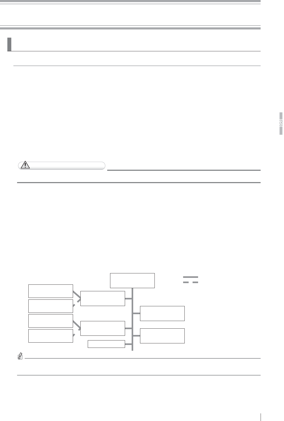
2.1 DR-ID 900PU
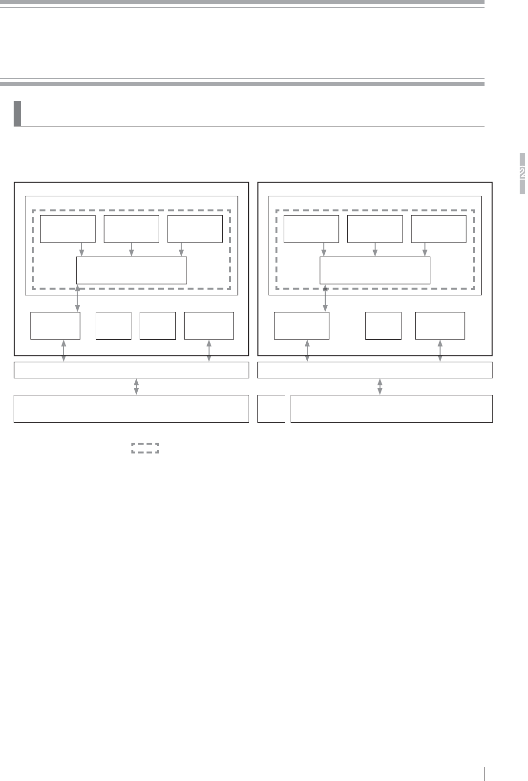
2.1.1 System Confi guration
For the U.S. For other countries
DR-ID 900
DR-ID 900PU
DR-ID 900
DR-ID 900PU
Image processing unit of other digital radiography system
DR-ID 300CL
Flat panel sensor Flat panel sensor Flat panel sensor
Battery
charger
Access
point
Power supply unit
DR-ID 900MP
Control cabinet
DR-ID 900MC
Image
processing unit
DR-ID 900CL
Ethernet switch (Hub)
Access
point
Flat panel sensor
Image processing unit of other digital radiography system
DR-ID 300CL
Flat panel sensor Flat panel sensor
Battery
charger
Power supply unit
DR-ID 900MP
Control cabinet
DR-ID 900MC
Image
processing unit
DR-ID 900CL
Ethernet switch (Hub)
• The products in can be installed in patient environment.
• The FDR D-EVO Advanced consists of the DR-ID 900RU and the image processing unit.
• An access point is used only in wireless communication mode.
* The confi guration of the system varies depending on the country.
• One to four fl at panel sensors can be connected to one power supply unit. If you connect all four
fl at panel sensors in wired communication mode or use them with three different techniques, two
power supply units are required.
• The fl at panel sensor can be used in wireless communication mode or wired communication mode.
• Up to four fl at panel sensors can be connected in wired or wireless communication mode in DR-ID
900PU.
However, either of the following conditions must be met:
a) Two DR-ID 911SE fl at panel sensors are connected in wired communication mode. (More
than three fl at panel sensors cannot be connected in wired communication mode.)
b) Any two of the DR-ID 601SE, DR-ID 602SE, DR-ID 611SE and DR-ID 613SE fl at panel
sensors are connected in wired communication mode.
2-2
System Configuration (Product Overview)
2
DR-ID 900PU Operation Manual 897N102280A
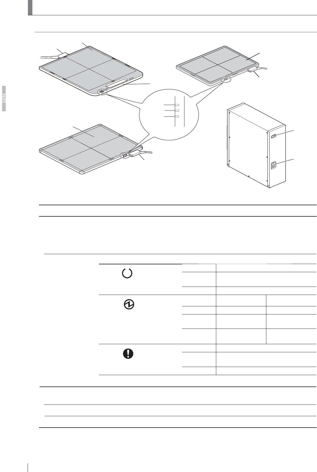
2.2 Unit Names and the Functions
Unit names and the functions of the DR-ID 900PU are described below.
Main switch
Power
status LED
Power supply unit (DR-ID 900MP)
Connector
Applied part
Connector
Handle
Applied part
Status lamp
READY
POWER
ERROR
Applied part
Connector
Flat panel sensor
(DR-ID 601SE, DR-ID 602SE and DR-ID 611SE)
Flat panel sensor
(DR-ID 911SE)
Flat panel sensor
(DR-ID 613SE)
* Exposure plane is shown in this figure.
Name Description
Flat panel sensor
DR-ID 911SE, DR-
ID 601SE, DR-ID
602SE, DR-ID 611SE
and DR-ID 613SE
They incorporate a GOS indirect panel. However, the DR-ID 611SE and DR-ID 613SE
incorporates a CsI indirect panel.
Wireless communication mode or wired communication mode can be used.
Status lamp Indicates the equipment status by LEDs.
READY (Green)
On Exposure possible
Blinks for 1.0
second.
During exposure sequence
Off Ready
POWER (Green)
(In wireless communication
mode, the status of the battery
pack is indicated. In wired
communication mode, the power
status is indicated.)
Wireless Wired
On OK (Power ON) Power ON
Blinks for 1.0
second.
Less than 10 min. _
Off Empty
(Power OFF)
Power OFF
ERROR (Orange)
On Communication not possible.
Blinks for 1.0
second.
Error occurred
Off Normal
* All LEDs are off when the equipment is off.
Power supply unit
(DR-ID 900MP)
Supplies the power to the flat panel sensor and connects the flat panel sensor and the
control cabinet.
Main switch Supplies the power to the flat panel sensor and the inside of the power supply unit.
Power status LED Displays ON/OFF of the power supply unit.
2-3
System Configuration (Product Overview)
2
DR-ID 900PU Operation Manual 897N102280A
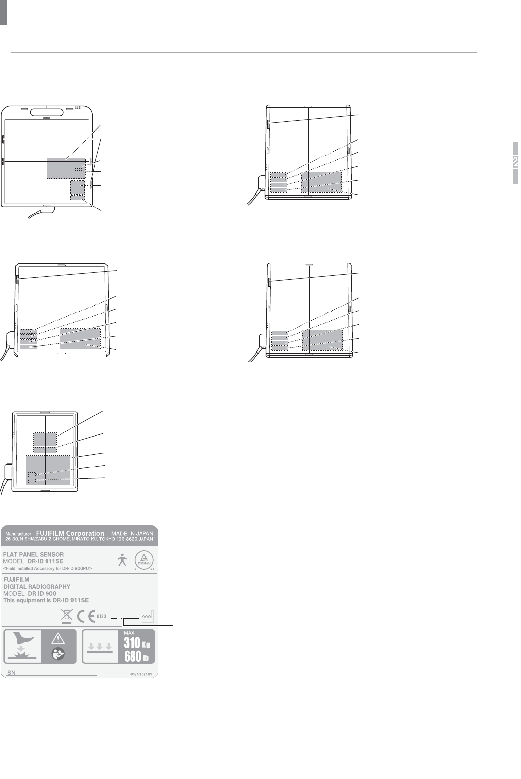
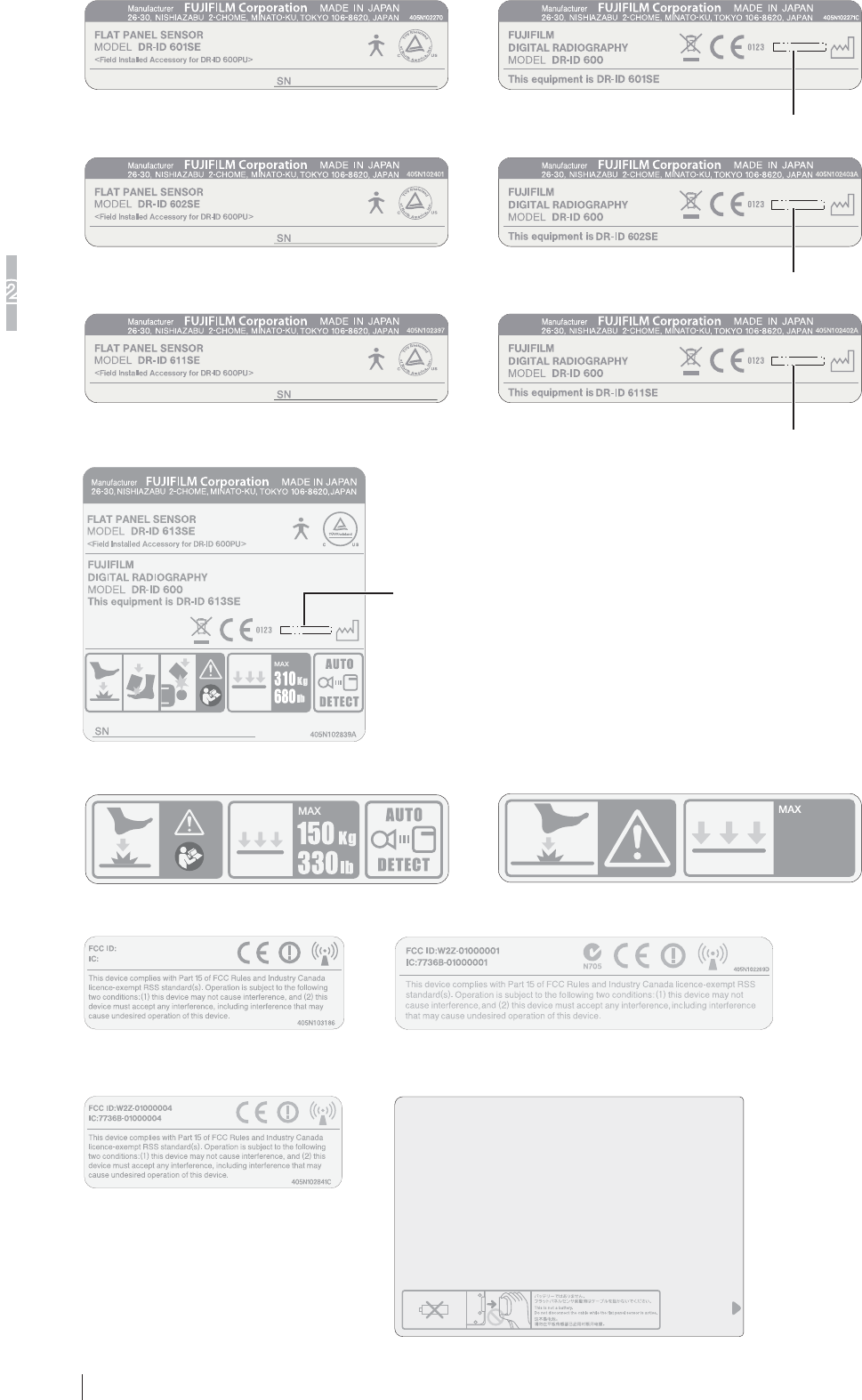
2.3 Locations of Labels and Signs
Locations of labels and signs affixed to the DR-ID 900RU, and the relevant safety signs are shown below.
2.3.1 Locations of Labels
DR-ID 601SE Caution Label
DR-ID 601SE CE Mark Label
DR-ID 601SE Identification Label
DR-ID 601SE
Radio Law Certification Label
Battery Cover Label
Color Label
<Exposure plane>
Flat panel sensor (DR-ID 601SE)
DR-ID 911SE Identification Label/
DR-ID 911SE CE Mark Label/
DR-ID 911SE Caution Label
DR-ID 911SE
Radio Law Certification Label
Battery Cover Label
Color Label
DR-ID 911SE Caution Label 1
DR-ID 911SE Caution Label 2
<Exposure plane>
Flat panel sensor (DR-ID 911SE)
DR-ID 611SE Caution Label
DR-ID 611SE CE Mark Label
DR-ID 611SE Identification Label
DR-ID 611SE
Radio Law Certification Label
Battery Cover Label
Color Label
<Exposure plane>
Flat panel sensor (DR-ID 611SE)
DR-ID 602SE Caution Label
DR-ID 602SE CE Mark Label
DR-ID 602SE Identification Label
DR-ID 602SE
Radio Law Certification Label
Battery Cover Label
Color Label
<Exposure plane>
Flat panel sensor (DR-ID 602SE)
DR-ID 613SE
Radio Law Certification Label
DR-ID 613SE
Identification Label
Battery Cover Label
DR-ID 613SE Caution Label 1
DR-ID 613SE Caution Label 2
Flat panel sensor (DR-ID 613SE)
<Exposure plane>
DR-ID 911SE Identification Label/DR-ID 911SE CE
Mark Label/DR-ID 911SE Caution Label
Sample year of
manufacture
2-4
System Configuration (Product Overview)
2
DR-ID 900PU Operation Manual 897N102280A
DR-ID 601SE Identification Label DR-ID 601SE CE Mark Label
Sample year of manufacture
Sample year of manufacture
DR-ID 602SE Identification Label DR-ID 602SE CE Mark Label
Sample year of manufacture
DR-ID 611SE Identification Label DR-ID 611SE CE Mark Label
Sample year of
manufacture
DR-ID 613SE Identification Label
Kg
150
lb
330
DR-ID 601SE/DR-ID 602SE/DR-ID 611SE Caution Label
DR-ID 601SE/DR-ID 602SE/DR-ID 611SE
Radio Law Certification Label
DR-ID 911SE Radio Law
Certification Label
DR-ID 613SE Radio Law
Certification Label
Battery Cover Label
W2Z-01000005
7736B-01000005
2-5
System Configuration (Product Overview)
2
DR-ID 900PU Operation Manual 897N102280A
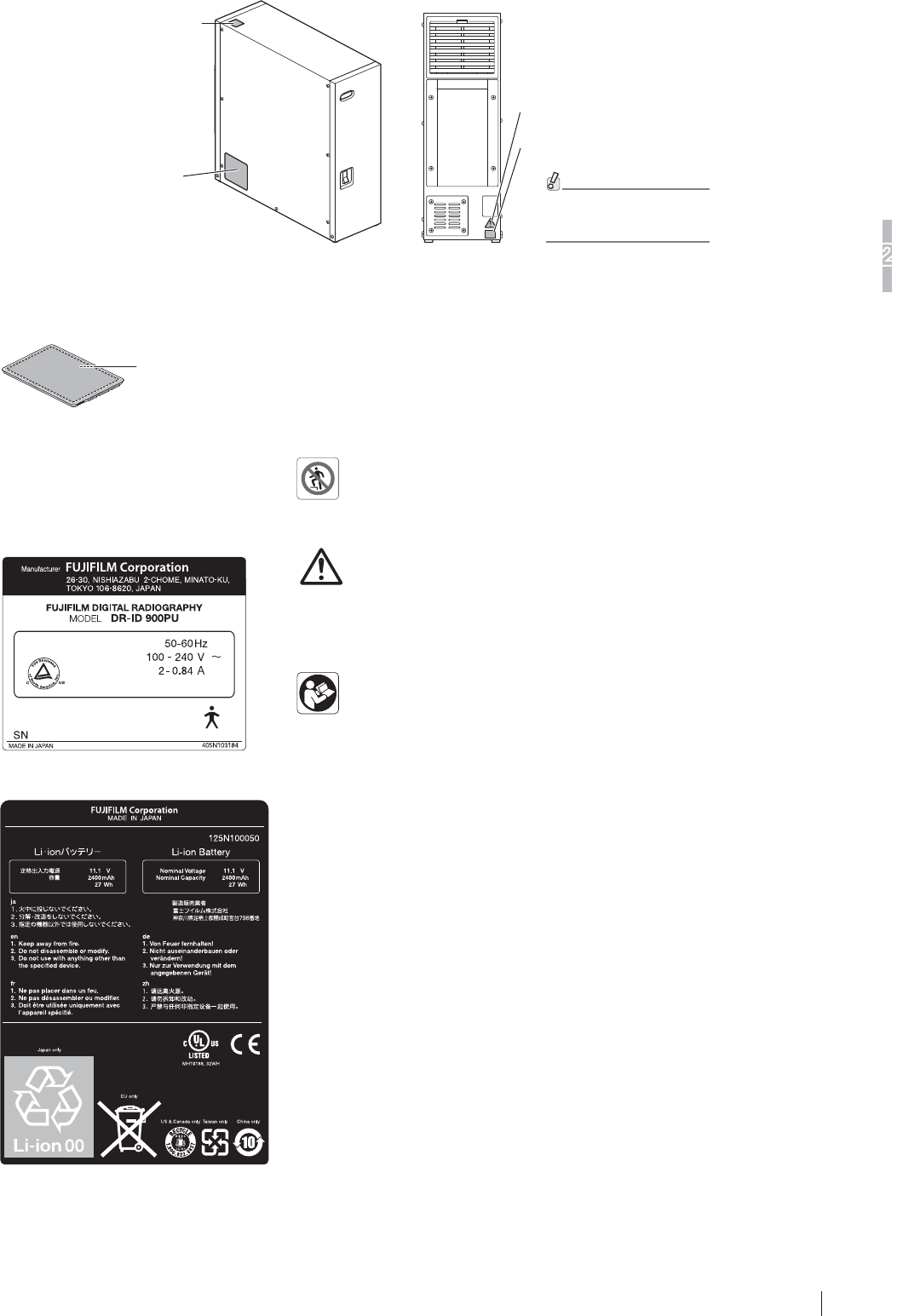
DR-ID 900PU Rating Label
DR-ID 900MP Caution Label 1
DR-ID 900MP
Caution Label 2
DR-ID 900MP
Caution Label 3
For the types of
connectable cables,
consult a FUJIFILM dealer.
<Left-hand side>
Power supply unit (DR-ID 900MP)
<Rear side>
Battery pack
(optional)
Battery pack
Rating Label
DR-ID 900PU Rating Label
DR-ID 900MP Caution Label 2 /
DR-ID 911SE Caution Label 1 /
DR-ID 613SE Caution Label 1
DR-ID 900MP Caution Label 3 /
DR-ID 911SE Caution Label 2 /
DR-ID 613SE Caution Label 2
DR-ID 900MP Caution Label 1
Battery Pack Rating Label
2-6
System Configuration (Product Overview)
2
DR-ID 900PU Operation Manual 897N102280A
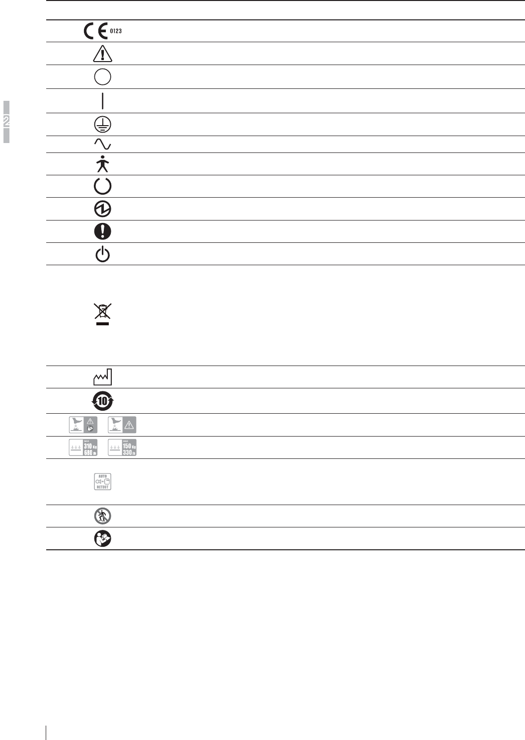
2.3.2 Safety and Other Symbols
The following safety symbols are used in the labels or on its body.
Symbol Description
This symbol indicates compliance of the equipment with Directive 93/42/EEC.
Caution (See “2.3.1 Locations of Labels” (page 2-3).)
OFF (To indicate disconnection from the mains, at least for mains switches or their
positions, and all those cases where safety is involved.)
ON (To indicate connection to the mains, at least for mains switches or their positions, and
all those cases where safety is involved.)
Protective earth (ground)
Alternating current
This symbol indicates that the equipment is a Type B Applied Part.
Ready (To indicate the machine is ready for operation.)
Electric energy
General mandatory action sign
Stand-by
This symbol indicates that this product is not to be disposed of with your household waste,
according to the WEEE Directive (2002/96/EC) and your national law. This product should
be handed over to a designated collection point.
Improper handling of this type of waste could have a possible negative impact on the
environment and human health due to potentially hazardous substances that are generally
associated with EEE.
At the same time, your cooperation in the correct disposal of this product will contribute to
the effective usage of natural resources.
For more information about waste, please contact FUJIFILM dealers.
Year of manufacture
Environmentally Friendly Use Period (EFUP)
/ Caution for local load
/ Entire surface load
This symbol indicates that the flat panel sensor supports the automatic X-ray detection
function. With this function, operations for making an exposure start when the flat panel
sensor detects X-rays.
* This function is not supported by the DR-ID 900PU.
No Stepping on Surface
Refer to Instruction Manual/Booklet
3-1
Basic Operation
3
DR-ID 900PU Operation Manual 897N102280A
Chapter 3 Basic Operation
3.1 Preparing the Flat Panel Sensor
This section describes how to prepare the flat panel sensor.
3.1.1 Type of Flat Panel Sensor
Wireless communication mode or wired communication mode is available. When used in wireless
communication mode, an access point*
1
, battery pack (optional) and battery charger (optional) are required.
*1 In the countries other than the U.S., an access point is not included as a component of the system. For
details including installation, consult our official dealer.
• Product compliant with IEC60950, UL60950, PSE or JIS
• Compliant with IEEE802.11n [W52] (in the 5.2GHz band) /36, 40, 44, 48ch
• WLAN interface: 1000BASE-T/100BASE-TX (minimum requirements)
• LAN interface: 1000BASE-T/100BASE-TX (minimum requirements)
• Available OS: Linux
• Compliant with UL
• Compliant with FCC part15
CAUTIONS
Use only one access point. A communication error may occur if two units or more are used.
3.1.2 Number of the Connectable Flat Panel Sensors
To enable the flat panel sensor, its ID needs to be registered in advance by a FUJIFILM dealer.
Up to five flat panel sensors can be registered.
Up to four flat panel sensors can be connected in wired or wireless communication mode in DR-ID
900PU.
However, either of the following conditions must be met:
a) Two DR-ID 911SE flat panel sensors are connected in wired communication mode. (More than
three flat panel sensors cannot be connected in wired communication mode.)
b) Any two of the DR-ID 601SE, DR-ID 602SE, DR-ID 611SE and DR-ID 613SE flat panel
sensors are connected in wired communication mode.
(Connection example)
Image processing unit
Control cabinet
(DR-ID 900MC)
Ethernet switch
(Hub)
Flat panel sensor
Flat panel sensor
Flat panel sensor
Flat panel sensor
Wired communication mode
Wireless communication mode
Power supply unit
(DR-ID 900MP)
Power supply unit
(DR-ID 900MP)
Access point
When multiple flat panel sensors are connected, make sure that the READY lamp among the status lamps of the
flat panel sensor to be used for an exposure is lit.
3-2
Basic Operation
3
DR-ID 900PU Operation Manual 897N102280A
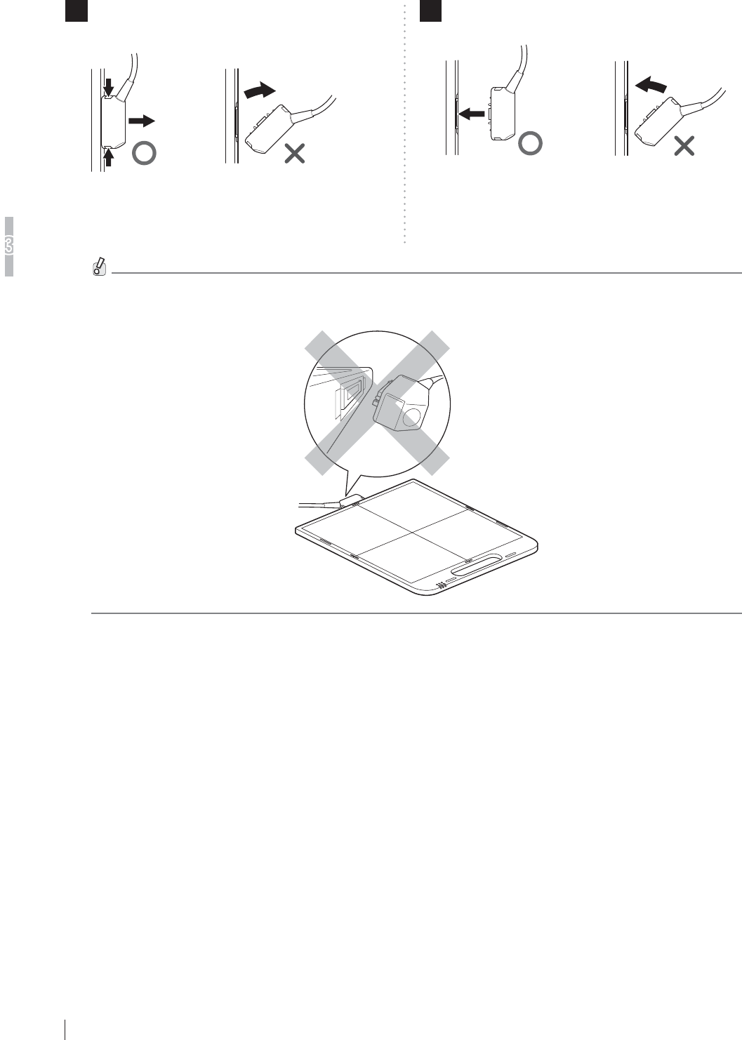
1 Disconnect the connector.
Press the latches on both sides of the connector.
2 Connect the connector.
Press the connector into the insertion section.
Make sure that the latches on both sides are
properly engaged when connecting the connector.
If the flat panel sensor is used with the connector
inserted incompletely, the flat panel sensor may turn
off.
Connect/Disconnect the connector straight to the flat panel sensor. If connected/disconnected at an angle, the
connector may be damaged.
3.1.3
Connecting/Disconnecting the Flat Panel Sensor Connector
When used in wireless communication mode, disconnect the connector.
3-3
Basic Operation
3
DR-ID 900PU Operation Manual 897N102280A
3.1.4 Inserting/Removing the Flat Panel Sensor into/from the
Radiographic Examination Stand
[1] In the case of the flat panel sensor DR-ID 911SE
The DR-ID 911SE cannot be mounted to any radiographic examination stand other than one
specified by FUJIFILM Corporation.
For details, refer to the operation manual of the radiographic examination stand.
[2]
In the case of the flat panel sensors DR-ID 601SE/
DR-ID 602SE/DR-ID 611SE/DR-ID 613SE
Follow the procedure below to insert/remove the flat panel sensor into/from the radiographic
examination stand.
For details, see the Operation Manual for the radiographic examination stand
CAUTIONS
For the positioning at the time of inserting/removing the flat panel sensor, see the Operation
Manual for the radiographic examination stand.
CAUTIONS
Be careful not to have your fingers caught when inserting/removing the flat panel sensor into/
from the radiographic examination stand.
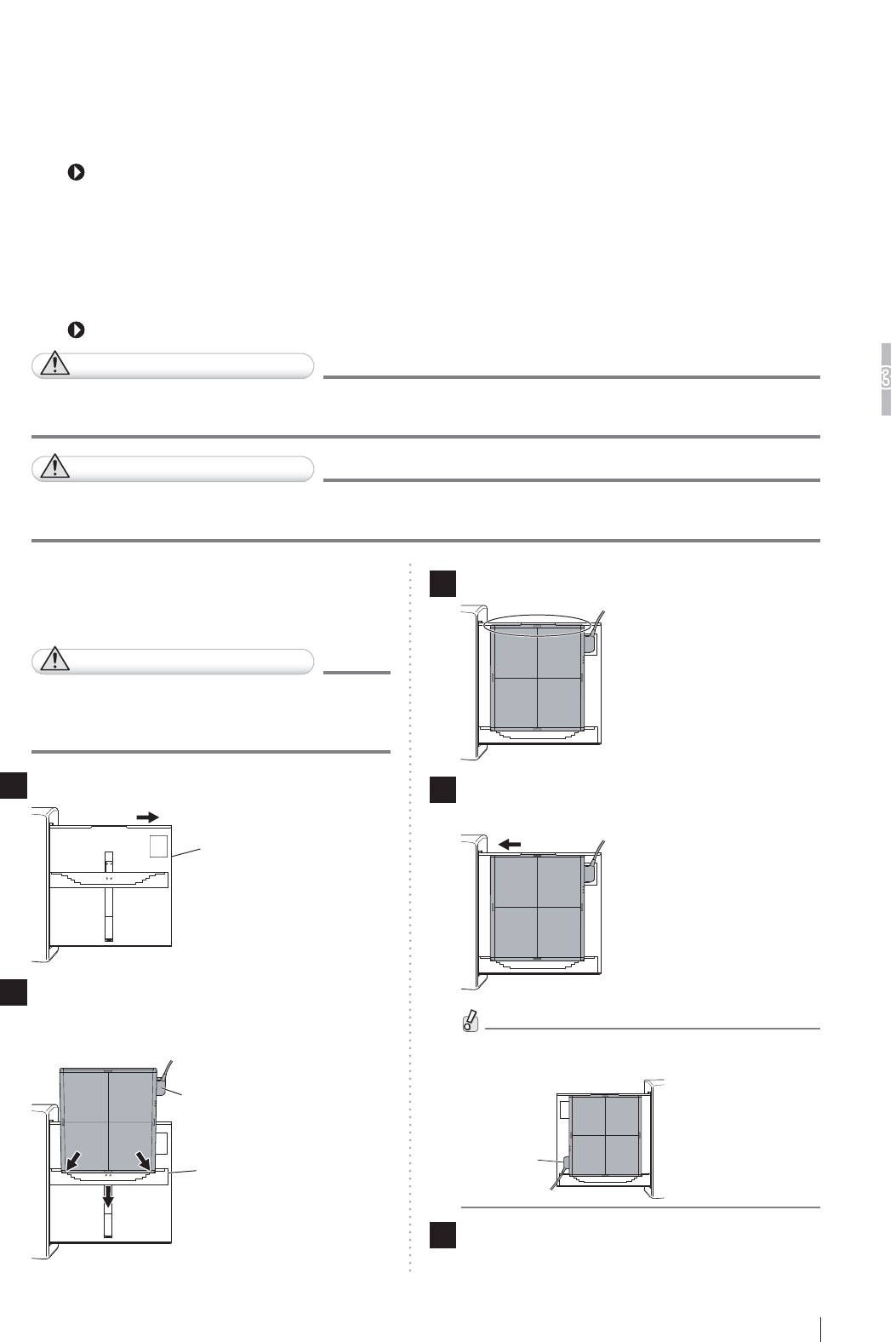
[1] Upright type
When inserting from the right-hand side
CAUTIONS
When inserting the flat panel sensor into
the radiographic examination stand, direct
the exposure plane toward the X-ray tube.
1 Pull out the tray.
Tray
2
Insert the flat panel sensor into the cassette
receive while the connector directed to the
upper right, and then move it downwards.
Connector
Cassette receive
3
Set the flat panel sensor to the upper part of the tray.
4 Push the tray back into place after setting
the flat panel sensor.
When inserting the flat panel sensor from the left-
hand side, direct the connector to the lower left.
Connector
5 Remove the flat panel sensor after use.
Pull out the tray, push the cassette receive
downwards, and then remove the flat panel sensor.
Push the tray back into place.
3-4
Basic Operation
3
DR-ID 900PU Operation Manual 897N102280A
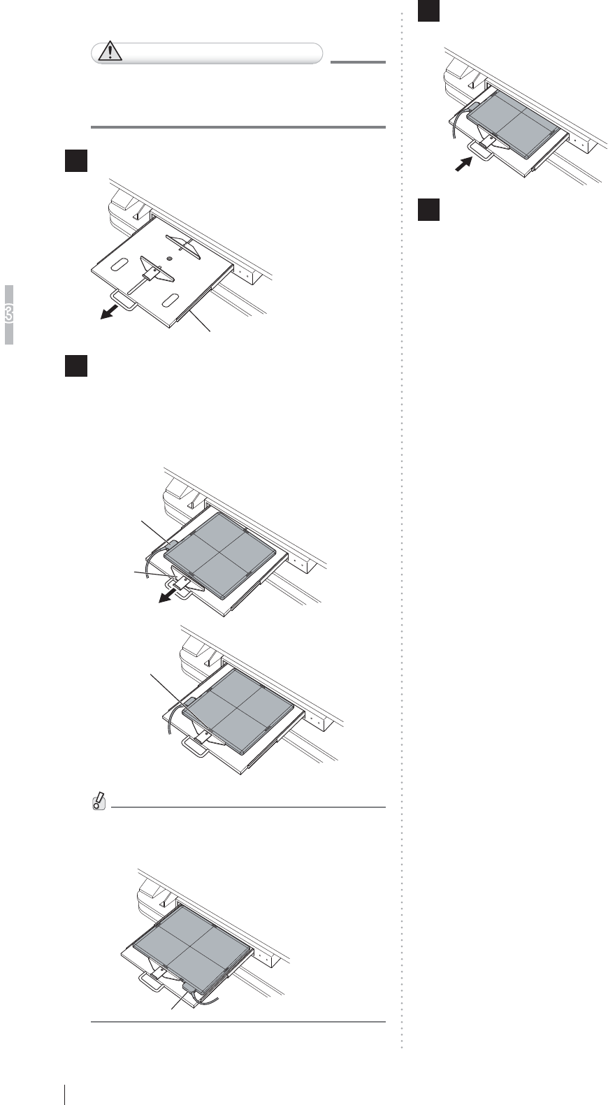
[2] Bed type
CAUTIONS
When inserting the flat panel sensor
to the radiographic examination stand,
direct the exposure plane upwards.
1 Pull out the tray by using the handle.
Tray
2 Pull the cassette stopper, and set the flat
panel sensor so that its center mark is
aligned with the center of the stopper.
Position the connector of the flat panel sensor as
shown in the figure below.
Cassette
stopper
Connector
Center mark
When setting the flat panel sensor horizontally,
position the connector as shown in the figure
below.
Connector
3 Push the tray back into place by using the
handle after setting the flat panel sensor.
4 Remove the flat panel sensor after use.
Hold the handle and pull out the tray. Remove the
flat panel sensor while pulling the cassette stopper,
and then push the tray back into place.

3-5
Basic Operation
3
DR-ID 900PU Operation Manual 897N102280A
3.1.5
Changing the Direction of the Flat Panel Sensor Connector
The direction of the connector of the flat panel sensor can be changed, depending on how it is
inserted into the radiographic examination stand.
To change the direction, contact a FUJIFILM dealer.
When shipped After changing the direction
3.1.6 Charging the Battery Pack (optional) for the Flat Panel
Sensor
Use the battery charger recommended by FUJIFILM Corporation.
For details on operations, refer to the instruction manual for the battery charger.
3-6
Basic Operation
3
DR-ID 900PU Operation Manual 897N102280A
3.1.7
Installing/Removing the Battery Pack (optional) for the Flat
Panel Sensor
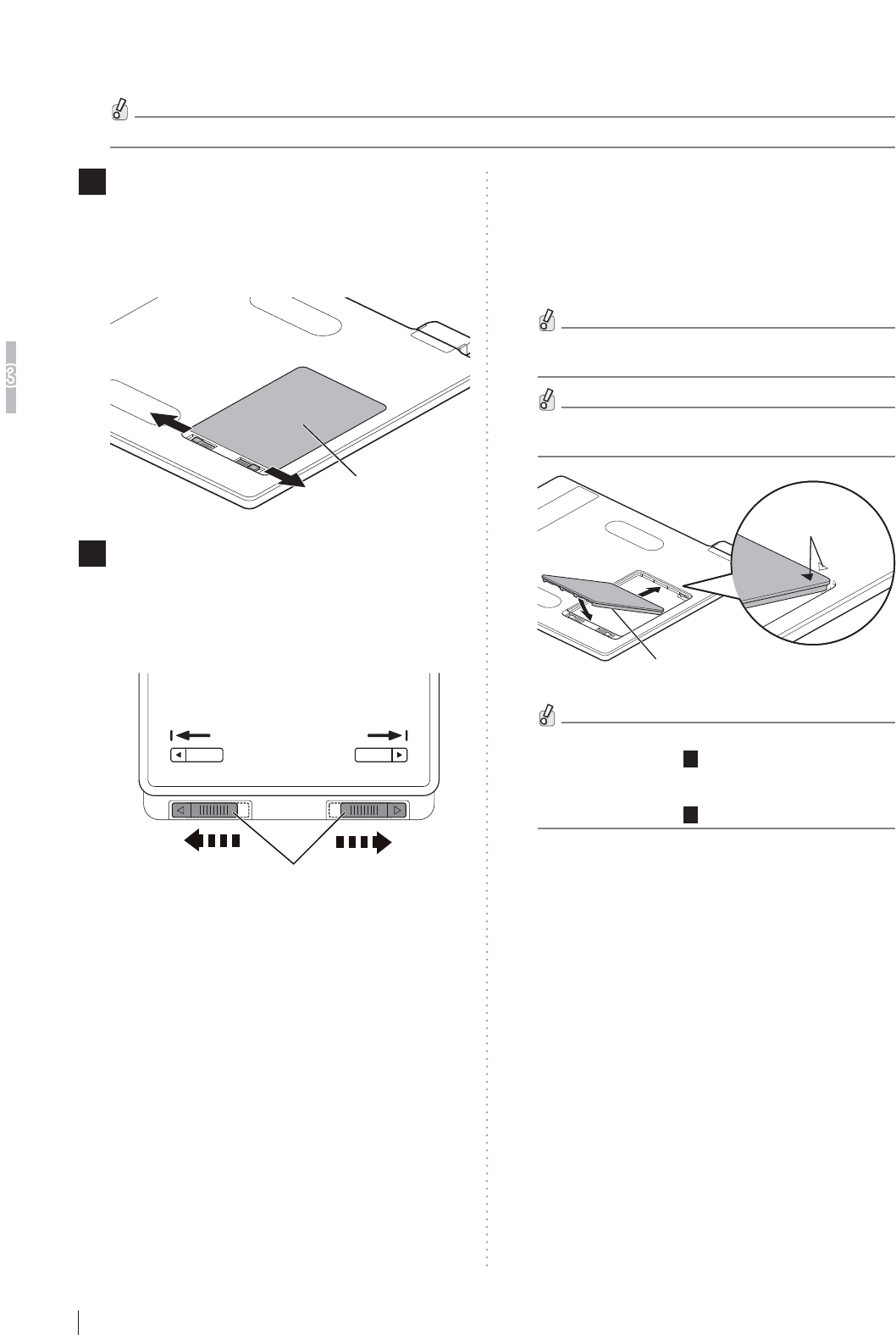
Follow the procedure below to install/remove the battery pack for the flat panel sensor.
When installing/removing the battery pack, place the flat panel sensor on a flat place.
1 Remove the battery cover.
Place the flat panel sensor with the back side facing
upward, and then simultaneously slide both the
battery lock release latches outward to remove the
battery cover.
Battery cover
2 Install the battery pack.
Make sure that the battery lock release latches are
released.
When the battery lock release latches are
released
Battery lock release latches
Slide the battery pack along the dent of the battery
section of the flat panel sensor toward the connector
terminal. Align the guide mark of the battery pack
with that of the flat panel sensor, and push the
battery pack in to install it.
Make sure that battery pack is securely installed.
Pushing the battery pack in with the guide marks
misaligned may damage the connector terminal.
When the battery pack is installed, the power is
automatically turned on.
Battery pack
Guide marks
• To remove the battery pack, perform the same
procedure as Step 1 (removing the battery
cover).
• To install the battery cover, perform the same
procedure as Step 2 (installing the battery pack)

3-7
Basic Operation
3
DR-ID 900PU Operation Manual 897N102280A
3.2 Starting Up and Shutting Down the
DR-ID 900PU
This section explains how to start up and shut down the DR-ID 900PU.
3.2.1 Starting Up the DR-ID 900PU
1 Press the ON side of the main switch of the power supply unit.
Start up the DR-ID 900PU with the initial settings properly made by our official dealer.
3.2.2 Shutting Down the DR-ID 900PU
1 Press the OFF side of the main switch of the power supply unit.

3-8
Basic Operation
3
DR-ID 900PU Operation Manual 897N102280A
4-1
Daily Inspection and Maintenance
4
DR-ID 900PU Operation Manual 897N102280A
Chapter 4 Daily Inspection and
Maintenance
4.1 Daily User Inspection and Maintenance
During maintenance and inspection, strictly observe precautions contained in “Chapter 1 For Safe
Operation” in this manual for you to use the DR-ID 900PU under best conditions.
4.1.1 Periodical Inspection
Inspection Every Three Months
Using a vacuum cleaner, remove any dirt or dust accumulated in each unit of the equipment once
every three months. Clean then with a slightly moistened soft cloth and wipe off any moisture with a
dry cloth.
See “2.2 Unit Names and the Functions” (page 2-2).
No. Unit No. Unit No. Unit
1Flat panel sensor 2Power supply unit 3Power supply unit
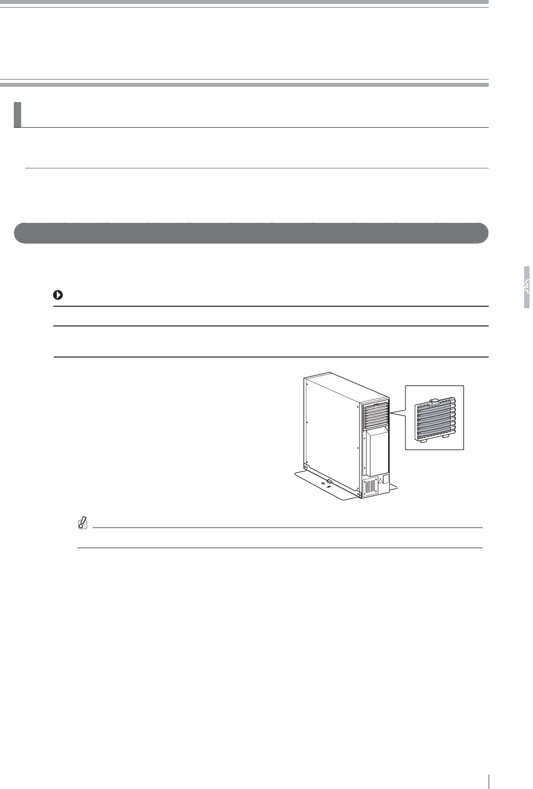
Air filter (1)
Air filter
Clean the air filter on the rear of the power
supply unit with a vacuum cleaner. Push
down the lever at the top of the louver-and-
filter assembly, and clean the air filter with a
vacuum cleaner after detaching it from the
assembly.
Air filter
Be sure to turn off the equipment before cleaning the air filter or the remote switch (optional).

4-2
Daily Inspection and Maintenance
4
DR-ID 900PU Operation Manual 897N102280A

A-1
Appendix A Specifications
DR-ID 900PU Operation Manual 897N102280A
Appendix A Specifications
A.1 Specifications
Specifications of the DR-ID 900PU are shown below.
A.1.1 Reduced Equivalent (DR-ID 900)
Peak reduced equivalent on the front panel of the flat panel sensor: 0.5 mmAl
A.1.2 Power Supply Conditions
Rated voltage : 100 - 240 V ~
Input current : 2 - 0.84 A
Frequency : 50 - 60 Hz
A.1.3 Environmental Conditions
(1) Operating Conditions
Temperature : 15°C (15%RH) - 30°C (80%RH)
Humidity : 15%RH (15°C) - 80%RH (30°C) (no dew condensation)
Atmospheric pressure : 700hPa - 1060hPa
(2) Non-operating Conditions
(Environmental conditions under which power can be supplied)
Temperature : 5°C - 35°C (no dew condensation)
Humidity : 10%RH - 80%RH (no dew condensation)
Atmospheric pressure : 700hPa - 1060hPa
A.1.4 Image performance
The flat panel sensors comply with the IEC 62220-1 standard (Medical electrical equipment
–Characteristics of digital X-ray imaging devices) as general X-ray devices.
To ensure optimal image quality, it is recommended that you do not use the flat panel sensor near
devices (motor, transformer, switching supply, etc.) that generate electromagnetic noise.

A-2
Appendix A Specifications
DR-ID 900PU Operation Manual 897N102280A
O-1
Appendix O Use of Optional Items
DR-ID 900PU Operation Manual 897N102280A
Appendix O Use of Optional Items
O.1 Optional Items
Name Description
Retaining bracket for MP A set of an anchor and a fixture, which is used for securing the power supply
unit to the floor.
For the external view, see “O.2 Using the Retaining Bracket for MP” (page O-2).
SE cable A cable that connects the flat panel sensor and the power supply unit(s).
When a second or third flat panel sensor is added to the system, this cable is
used for reconnecting flat panel sensors, for example.
X-ray camera connection cable A signal cable that connects the power supply unit and the X-ray equipment
(shot signal).
Cable length : 15m (49.2 ft)
Battery pack A battery pack for the flat panel sensor.
For precautions, charging and installing/removing, see pages 1-5, 1-6, 3-5
and 3-6.
Battery charger A battery charger for the battery pack.
For precautions, external view and charging, see pages 1-5, 1-6, 2-1 and 3-5.
O-2
Appendix O Use of Optional Items
DR-ID 900PU Operation Manual 897N102280A
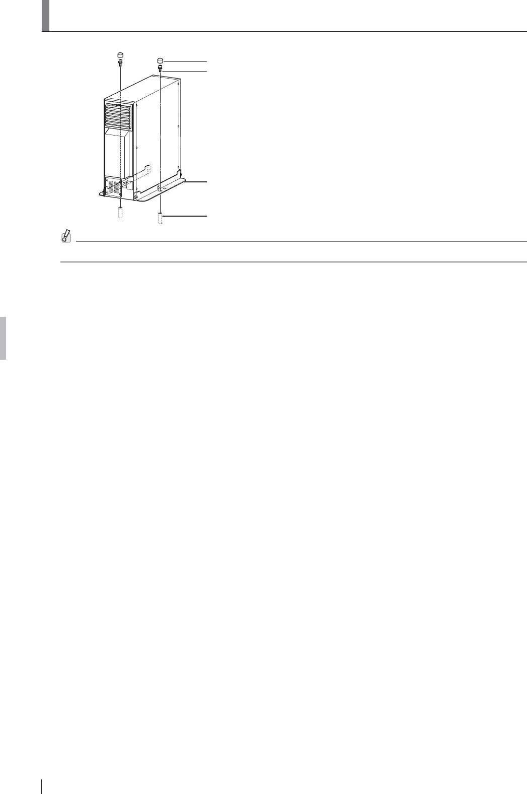
O.2 Using the Retaining Bracket for MP
Cap
Bolt
Fixture
Anchor
Contact a FUJIFILM dealer for installation of the Retaining bracket for MP.

Maintenance and Inspection
FDR D-EVO Operation Manual 897N101473L
Radio frequency (RF) compliance information
Compliance with Part 15 of FCC Rules and
Industry Canada licence-exempt RSS standard(s).
This device complies with Part 15 of FCC Rules and Industry Canada licence-exempt RSS standard(s).
Operation is subject to the following two conditions:
(1) this device may not cause interference, and (2) this device must accept any interference, including
interference that may cause undesired operation of this device.
Le présent appareil est conforme aux la partie 15 des règles de la FCC et CNR d’Industrie Canada
applicables aux appareils radio exempts de licence. L’exploitation est autorisée aux deux conditions
suivantes : (1) l’appareil ne doit pas produire de brouillage, et (2) l’utilisateur de l’appareil doit accepter tout
brouillage radioélectrique subi, même si le brouillage est susceptible d’en compromettre le fonctionnement.
FCC CAUTION
Changes or modifications not expressly approved by the party responsible for compliance could void the
user’s authority to operate the equipment.
The available scientific evidence does not show that any health problems are associated with using low
power wireless devices.
There is no proof, however, that these low power wireless devices are absolutely safe. Low power
Wireless devices emit low levels of radio frequency energy (RF) in the microwave range while being
used. Whereas high levels of RF can produce health effects (by heating tissue), exposure of low-level RF
that does not produce heating effects causes no known adverse health effects. Many studies of low-level
RF exposures have not found any biological effects.
Some studies have suggested that some biological effects might occur, but such findings have not been
confirmed by additional research. DR-ID 601SE/DR-ID 602SE/DR-ID 611SE/DR-ID 612SE/DR-ID 613SE
has been tested and found to comply with FCC/IC radiation exposure limits set forth for an uncontrolled
environment and meets the FCC radio frequency (RF) Exposure Guidelines in Supplement C to OET65
and RSS-102 of the IC radio frequency (RF) Exposure rules.
Les connaissances scientifiques dont nous disposons n’ont mis en évidence aucun problème de santé
associé à l’usage des appareils sans fil à faible puissance. Nous ne sommes cependant pas en mesure
de prouver que ces appareils sans fil à faible puissance sont entièrement sans danger. Les appareils sans
fil à faible puissance émettent une énergie radioélectrique (RF) très faible dans le spectre des micro-ondes
lorsqu’ils sont utilisés. Alors qu’une dose élevée de RF peut avoir des effets sur la santé (en chauffant les
tissus), l’exposition à de faibles RF qui ne produisent pas de chaleur n’a pas de mauvais effets connus
sur la santé. De nombreuses études ont été menées sur les expositions aux RF faibles et n’ont découvert
aucun effet biologique. Certaines études ont suggéré qu’il pouvait y avoir certains effets biologiques,
mais ces résultats n’ont pas été confirmés par des recherches supplémentaires. DR-ID 601SE/DR-ID
602SE/DR-ID 611SE/DR-ID 612SE/DR-ID 613SE a été testé et jugé conforme aux limites d’exposition
aux rayonnements énoncées pour un environnement non contrôlé et respecte les règles d’exposition aux
fréquences radioélectriques (RF) CNR-102 de l’IC.
5.15-5.25GHz band is restricted to indoor operations only.
Labande 5150-5250 MHz est restreints à une utilisation à l’intérieur.
Compliance with FCC requirement 15.407(C) Data transmission is always initiated by software, which is
the passed down through the MAC, through the digital and analog baseband, and finally to the RF chip.
Several special packets are initiated by the MAC. These are the only ways the digital
baseband portion will turn on the RF transmitter, which it then turns off at the end of the
packet. Therefore, the transmitter will be on only while one of the aforementioned packets is being
transmitted.
In other words, this device automatically discontinue transmission in case of either absence of information
to transmitor operational failure.
(This transmitter must not be co-located or operated in conjunction with any other antenna or transmitter.)
DR-ID 900PU Operation Manual 897N102280A
911
3
3911
and RSS-102 of the IC radio
frequency (RF) Exposure rules.
Maintenance and Inspection
DR-ID 900PU Operation Manual 897N102280A
Maintenance and Inspection
1 Maintenance and Inspection Items Assigned to Specified Dealer
For periodical inspection of the equipment and necessary arrangements, consult our official dealer
or local representative.
Periodical Maintenance
Make sure that the periodical maintenance and inspection assigned to our official dealer are
performed as specified.
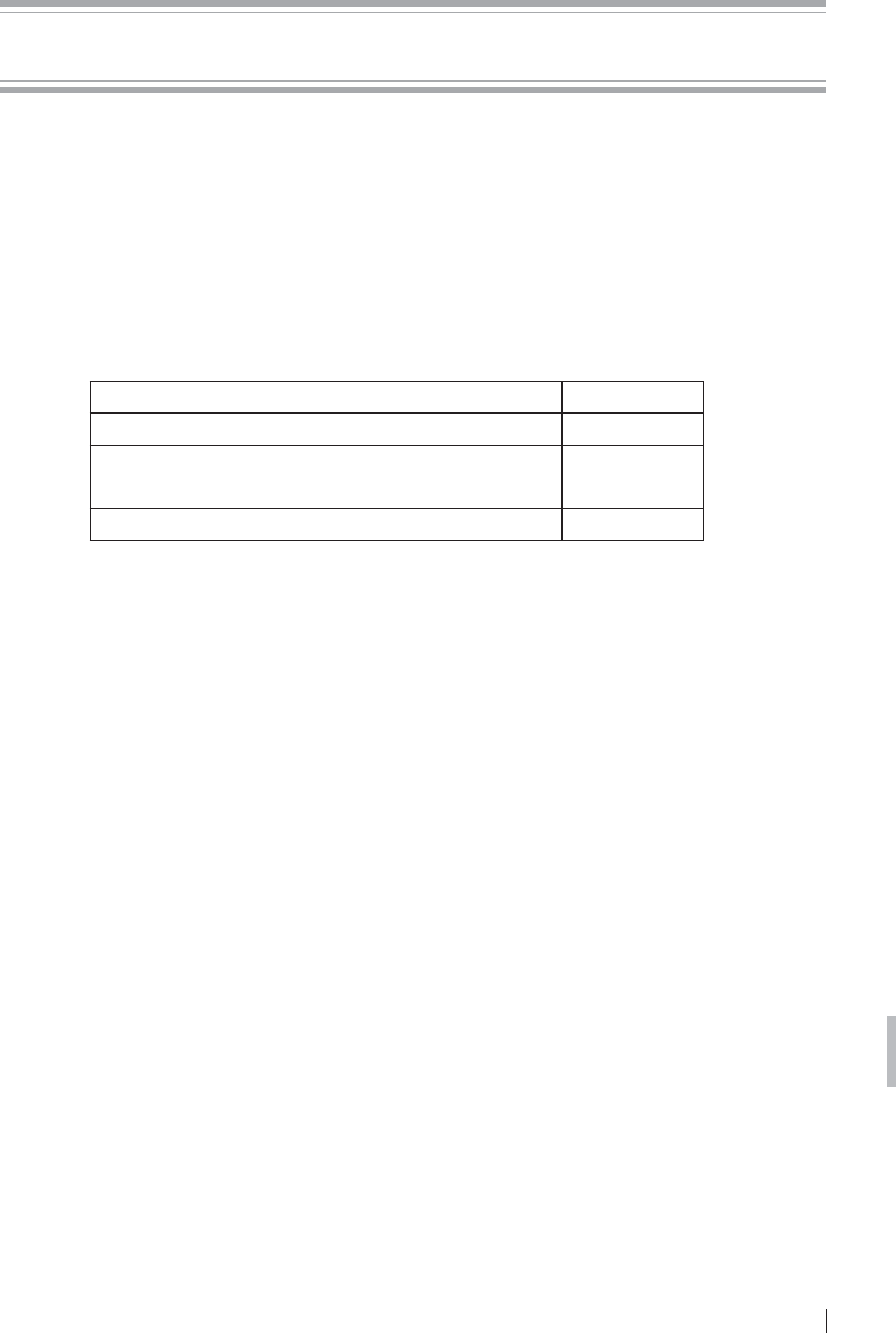
Maintenance and Inspection Items Assigned to Specified Dealer
Periodical Maintenance and Inspection Items Period
Checking of the image Every year
Checking of the operation record by referring to the error log Every year
Checking of the internal units Every 2 years
Checking of the S value Every 6 months
Main Periodical Replacement Parts
* It is recommended that the battery pack (optional) be replaced once a year.
If the duration of use exceeds one year, the capacity of the battery pack will decrease.
The cycles of periodical maintenance and inspection and of parts replacement differ depending on
the usage and the daily operation time.
For details, contact us directly or our official dealer.

FUJIFILM MEDICAL SYSTEMS U.S.A., INC.
419 WEST AVENUE, STAMFORD CT 06902, U.S.A.