Fujitsu Client Computing WL0007 LifeBook T Series Tablet PC w/WLAN WM3B2200BG User Manual WLAN
Fujitsu Limited LifeBook T Series Tablet PC w/WLAN WM3B2200BG WLAN
UserManual.wiki
>
Fujitsu Client Computing
>
WL0007 User Manual
>
WLAN User Manual
Contents
1.
Host PC User Manual
2.
WLAN User Manual
WLAN User Manual
Navigation menu
Upload a User Manual
Namespaces
Wiki Guide
HTML
PDF
Info
Views
User Manual
Discussion / Help
Navigation


![54STOPPING TRANSMISSION To use this product inside hospitals, clinics, or airplanes, or in other places where the use of electronic equipment is regulated, stop the transmission of radio waves from the wireless LAN beforehand.Deactivation using the wireless switchThe transmission of radio waves from the wireless LAN can be stopped by setting the wireless switch to the Off position. Note that the wireless LAN On/Off switch has no effect on non-wireless LAN models.(See Figure 3 for Wireless LAN switch location.)Figure A-3. Wireless LAN On/Off SwitchDeactivation using WindowsIntel PROSet Wireless LAN:1. Click [Start] --> [(All) Programs] --> [Intel Net-work Adapters] --> [Intel(R) PROSet]. The Intel(R) PROSet window will be displayed.2. Click the General tab.3. Select [Off] for the wireless communications Switch Radio: function, and then click the [OK] button. Wireless communications on/off switching will be deactivated and the transmission of radio waves from the wireless LAN will be stopped.Atheros Wireless LAN1. Click [Start] --> [Control Panel] --> [Atheros Cli-ent Utility]. The Atheros Wireless Configuration Utility window will be displayed.2. Click the Wireless Networks tab.3. Click the [Enable Radio] box to clear it, then click the [OK] button. Wireless communications on/off switching will be deactivated and the transmission of radio waves from the wireless LAN will be stopped.STARTING TRANSMISSION To communicate using the wireless LAN function, set the computer to a status from which it can transmit, as follows:Intel PROSet Wireless LAN:1. Set the wireless switch to the On position. 2. Click [Start] --> [(All) Programs] --> [Intel Net-work Adapters] --> [Intel(R) PROSet]. The Intel(R) PROSet window will be displayed.3. Click the [General] tab if it is not already selected.4. Select [ON] for the Switch radio: function, then click [OK]. Wireless communications on/off switching will be activated and the transmission of radio waves will be restarted.Atheros Wireless LAN:1. Click the Wireless Network Connection icon in the system tray at the lower right of your screen.2. Click [Enable Radio]. The radio will be turned on.Access Point Mode: Transmission is enabled.Ad Hoc Mode: Restart your computer to enable the radio.To restart transmission, select [On] for the wireless communications Switch Radio: function, and then click the [OK] button.Wireless LANOn/OffSwitchTo restart transmission, check the [Enable Radio] checkbox to select it., then click the [OK] button.](https://usermanual.wiki/Fujitsu-Client-Computing/WL0007.WLAN-User-Manual/User-Guide-407390-Page-7.png)
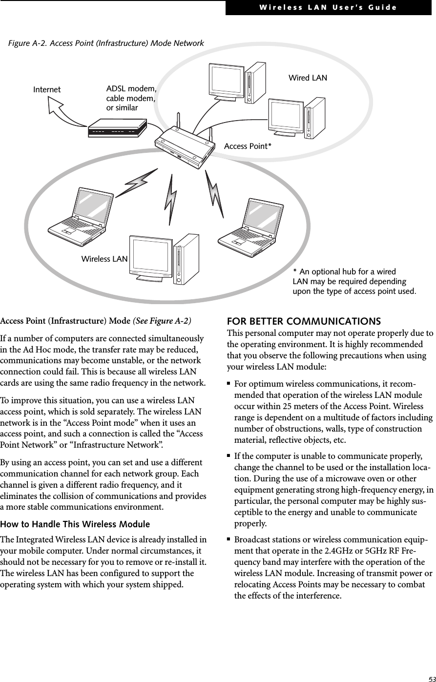
![55Wireless LAN User’s GuideConnecting the WLANFLOW OF OPERATIONSThe wireless LAN connection procedure contained in this section is outlined below.1. Make sure the mobile computer is ready for the transmission of radio waves from the wireless LAN. For further details, see (See Starting Transmission on page 54 for more information.).2. Assign the parameters required for wireless LAN connection. (See Preparation for wireless LAN con-nection on page 55 for more information.).■Configure network name (SSID).■Configure wireless LAN security parameters as appropriate (e.g., WEP, TKIP, 802.1x/EAP).3. Perform setting operations relating to network con-nection. (See Connection to the network on page 57 for more information.)■Specify TCP/IP as the protocol, and confirm the name of the work group and other settings.■Enter the data required for file/printer sharing on the network. Perform this operation as required.■For access point (or “infrastructure”) connection, configure the wireless module with appropriate parameters required to associate to the access point network.■Verify that you are able to connect your computer to the network.PREPARATION FOR WIRELESS LAN CONNECTIONThis section explains the preparations required to use the wireless LAN when using the Windows XP Wireless Zero Configuration Tool. Configuration can also be accomplished using the wireless module (Intel or Atheros) configuration utility.Assigning parametersEnter the network name (SSID), the network key, and other data required for wireless LAN connection. If there is the administrator of the network, contact the network administrator for data settings.1. Make sure the Wireless LAN switch is switched on.2. Click the [Start] button first and then [Control Panel].3. If the Control Panel is in Category view, switch to Classic view by clicking “Switch to Classic View” under Control Panel the left frame. (If you are already in Classic view, “Switch to Category View” will be displayed instead.) 4. Double-click the Network Connections icon. A list of currently installed networks will be displayed.5. Right-click [Wireless Network Connection] in the list, and then click [Properties] in the menu dis-played. The [Wireless Network Connection Proper-ties] window will be displayed.6. Click the [Wireless Networks] tab.7. Click [Refresh], then choose the correct SSID from the [Available Networks] window. Click [Config-ure] and proceed to step 7. If the SSID of your access point does not appear in the list, click [Add]. The [Wireless Network Properties] window will be displayed.8. Select the Association tab if it is not already selected.9. Enter the information required for connection to the wireless LAN.a. Enter the network name (SSID). (i.e., Enter the name of the desired network in less than 33 ASCII characters).■To use access point (infrastructure) con-nection, refer to the access point manual for the access point-setting procedure.■You do not need to set the channel when using access point (infrastructure) mode. Channel selection is controlled by the access point. In ad hoc networks, channel selection defaults to channel 11; however, channel selection can be man-ually changed if desired. This can be accomplished only when using the client utility.If it is necessary to change the channel, change the setting of the access point. For the setting procedure, refer to the manual of the access point.](https://usermanual.wiki/Fujitsu-Client-Computing/WL0007.WLAN-User-Manual/User-Guide-407390-Page-8.png)
![56For ad hoc connection: Assign the same network name to all the personal computers to be connected.For access point (infrastructure) connection: Assign the appropriate SSID. The SSID must be identical to the SSID of the access point. Refer to the access point manual, or contact your network administrator.b. For ad hoc connection, check the following field. For access point (infrastructure) connection, clear the check mark for the following field:[This is a computer-to-computer (ad hoc) net-work; wireless access points are not used.]10. Enter the WEP key for encoding communications data.a. Check the [Data encryption (WEP enabled)] check boxFor ad hoc connection: Clear the check mark from the [Network Authentication (Shared mode)] check box.For access point (infrastructure) connection: If the access point to be accessed is configured for shared-key authentication, check the [Network Authentication (Shared mode)] check box.For open-system authentication, clear the check mark. For access point setting, refer to the man-ual of the access point.b. Clear the check mark from the [The key is provided for me automatically] check box.c. Enter data in [Network Key]. Depending on the number of entered characters or digits, whether the key is an ASCII character code or a hexadec-imal code will be identified automatically.Use five or thirteen characters to enter the key in the ASCII character code format. The char-acters that can be used as the “network key” are as follows: 0 - 9, A - Z, _ (underscore), or, Use 10 or 26 characters to enter the key in the hexadecimal character code format. The char-acters that can be used as the “network key” in this case are as follows: 0- 9, A - Z, a - fFor ad hoc connection: Assign the same net-work key to all the personal computers to be connected.For access point (infrastructure) connection: Assign the identical network key that is pro-grammed into the access point. For this set-ting, refer to the access point manual or contact your network administrator.d. Confirm the Network key by re-entering the same data in the [Confirm network key:] field.e. Make sure that [Key index (advanced)] is set to “1”. (Any value from “1” to “4” can be assigned to [Key index (advanced)]. “1” is usually assigned, however).11. Click the [Authentication] tab and then verify the settings of [Enable network access control using IEEE 802.11x].For internal use at an organization such as a com-pany, when access by wireless LAN clients is to be limited using IEEE 802.11x authentication, check the [Enable network access control using IEEE 802.11x] check box.For home use, clear the check mark from [Enable network access control using IEEE 802.11x]. For the setting method relating to IEEE 802.11x authentication, refer to the manual of the access point which you are using.12. After completion of setting operations, click the [OK] button. Processing will return to the [Wire-less Network Connection Properties] window.13. Verify that the network name entered in step 7 above is added in [Preferred Networks], and then click the [OK] button.14. Close the [Wireless Network] window.It is strongly recommended that you enter the network key for encoding communications data. If the network key is not entered, since the network can be accessed from all personal computers containing the wireless LAN function, there is the danger of your data being stolen or damaged by other users.In [Preferred Networks], register only the desired connection settings.](https://usermanual.wiki/Fujitsu-Client-Computing/WL0007.WLAN-User-Manual/User-Guide-407390-Page-9.png)
![57Wireless LAN User’s GuideCONNECTION TO THE NETWORKThis section explains connection to the network.If there is an administrator of the network, contact the network administrator for data settings.Setting the networkPerform the “Setting TCP/IP” and “Confirming the computer and work group names” operations required for network connection.Setting TCP/IP1. Click the [Start] button first and then [Control Panel].2. If the Control Panel is in Category view, switch to Classic view by clicking “Switch to Classic View” under Control Panel the left frame. (If you are already in Classic view, “Switch to Category View” will be displayed.) 3. Double-click [Network Connections]. A list of cur-rently installed networks will be displayed.4. Right-click [Wireless Network Connection] in the list, and then click [Properties] in the menu dis-played. The [Wireless Network Connection Proper-ties] window will be displayed.5. Click the [General] tab if it is not already selected.6. Click [Internet Protocol (TCP/IP] and then click [Properties]. The [Internet Protocol (TCP/IP) Properties] window will be displayed.7. Set the IP address as follows:■For ad hoc connection: Select [Use the following IP address:] and then enter data for [IP address] and [Subnet mask]. See page 66 for IP address setting.■For access point (infrastructure) connection: If your network uses DHCP, select [Obtain an IP address automatically] and [Obtain DNS server address automatically]. If your network uses static IP addresses, consult with your network adminis-trator for the correct IP address settings.8. Click the [OK] button. Processing will return to the [Wireless Network Connection Properties] window.9. Click the [OK] button.10. Close the [Network Connection] window. Following this operation, confirm the names of the computer and the workgroup as follows.Confirming the computer and work group names1. Click the [Start] button, then [Control Panel].2. If the Control Panel is in Category view, switch to Classic view by clicking “Switch to Classic View” under Control Panel the left frame. (If you are already in Classic view, “Switch to Category View” will be displayed.) 3. Double-click the [System] icon. The [System Prop-erties] window will be displayed.4. Click the [Computer Name] tab.5. Confirm the settings of [Full computer name:] and [Workgroup:].a. The setting of [Full computer name:] denotes the name for identifying the computer. Any name can be assigned for each personal computer. Enter the desired name in less than 15 ASCII character code format. Identifiability can be enhanced by entering the model number, the user name, and other factors.b. [Workgroup name] is the group name of the network. Enter the desired name in less than 15 ASCII character code format.For ad hoc connection: Assign the same network name to all personal computers existing on the network.For access point (infrastructure) connection: Assign the name of the work group to be accessed.6. Click the [OK] button. If a message is displayed that requests you to restart the personal computer, click [Yes] to restart the computer.Setting the sharing functionSet the sharing function to make file and/or printer sharing with other network-connected personal computers valid.To change the setting of the IP address, you need to be logged in from Windows as an administrator.To modify the computer name and/or the work group name, you need to be logged in from Windows as an administrator.To change the name, click [Change] and then proceed in accordance with the instruction messages displayed on the screen.](https://usermanual.wiki/Fujitsu-Client-Computing/WL0007.WLAN-User-Manual/User-Guide-407390-Page-10.png)
![58This operation is not required unless the sharing func-tion is to be used.The folder and printer for which the sharing function has been set will be usable from any personal computer present on the network.Setting the Microsoft network-sharing service1. Click the [Start] button first and then [Control Panel]. 2. If the Control Panel is in Category view, switch to Classic view by clicking “Switch to Classic View” under Control Panel the left frame. (If you are already in Classic view, “Switch to Category View” will be displayed.) 3. Double-click [Network Connections]. A list of cur-rently installed networks will be displayed.4. Right-click [Wireless Network Connection] in the list, and then click [Properties] in the menu dis-played. The [Wireless Network Connection Proper-ties] window will be displayed.5. If [File and Printer Sharing for Microsoft Net-works] is displayed, proceed to step 6. If [File and Printer Sharing for Microsoft Networks] is not dis-played, skip to step 7.6. Make sure that the [File and Printer Sharing for Microsoft Networks] check box is checked, and then click the [OK] button. Skip to “Setting file-sharing function”.7. Click [Install]. The [Select Network Component Type] window will be displayed.8. Click [Service], then click the [Add] button. The [Select Network Service] window will be displayed.9. Click [File and Printer Sharing for Microsoft Net-works] and then click the [OK] button. Processing will return to the [Wireless Network Connection Properties] window, and [File and Printer Sharing for Microsoft Networks] will be added to the list.10. Click the [Close] button.Setting the file-sharing functionThe procedure for setting the file-sharing function follows, with the “work” folder in drive C: as an example.1. Click the [Start] button first and then [My Com-puter]. 2. Double-click [Local disk (C:)].3. Right-click the “work” folder (or whichever folder you want to share), and then click [Sharing and Security...] in the menu displayed. The [Folder Name Properties] window will be displayed.4. Click [Sharing] if it isn’t already selected.5. Click the link stating “If you understand the secu-rity risks, but want to share files without running the wizard, click here”.6. Click “Just enable file sharing” and click [OK].7. Check the [Share this folder on the network] check box.8. Click the [OK] button. The folder will be set as a sharable folder, and the display of the icon for the “work.” folder will change.Setting the printer-sharing function1. Click the [Start] button first and then [Printers and FAX]. A list of connected printers will be displayed.2. Right-click the printer for which the sharing func-tion is to be set, and then click [Sharing] in the menu displayed. The property window correspond-ing to the selected printer will be displayed.3. Click the [Sharing] tab.4. Click [Share this printer].To share a file and/or the connected printer, you need to be logged in as an administrator.Setting the file-sharing function for the file which has been used to execute Network Setup Wizard is suggested on the screen. For the wireless LAN, however, since security is guaranteed by entry of the network name (SSID) and the network key, the steps to be taken to set the file-sharing function easily without using Network Setup Wizard are given below.To specify the corresponding folder as a read-only folder, select the [Read only] checkbox under the General tab.Setting the printer-sharing function when Network Setup Wizard has been executed is suggested on the screen. For the wireless LAN, however, since security is guaranteed by entry of the network name (SSID) and the network key, the steps to be taken to set the printer-sharing function without using Network Setup W izard are laid down below.](https://usermanual.wiki/Fujitsu-Client-Computing/WL0007.WLAN-User-Manual/User-Guide-407390-Page-11.png)
![59Wireless LAN User’s Guide5. Enter the sharing printer name in [Share name].6. Click the [OK] button. Confirming connectionAfter you have finished the network setup operations, access the folder whose sharing has been set for other personal computers. Also, confirm the status of the radio waves in case of trouble such as a network connection failure.Connecting your personal computer to another personal computer1. Click [Start] first and then [My Computer]. The [My Computer] window will be displayed in the left frame.2. Click [My Network Places] in the “Other Places” list. The window [My Network Places] will be dis-played.3. Click [View workgroup computers] under Network Tasks in the left frame.4. Double-click the personal computer to which your personal computer is to be connected. The folder that was specified in “Setting the file-sharing func-tion” on page 58 will be displayed.5. Double-click the folder to be accessed.Confirming the status of the radioIntel PROSet Wireless LAN:1. Click [Start] -> [All Programs] -> [Intel Network Adapters] -> [Intel(R) PROSet]. The [Intel(R) PROSet] window will be displayed.2. Click the [General] tab and confirm radio status in the window displayed. The current connection sta-tus will be displayed.■Signal QualityThe quality of the signals is displayed on a graph.■Network name (SSID)The connected network name (SSID) is displayed.■Profile name“<No profile>” is displayed.■ModeIf access point (infrastructure) connection is in use, “Infrastructure (AP)” will be displayed. If ad hoc connection is in use, “Ad hoc (Peer-to-peer)” will be displayed.■SecurityDisplays the encryption type currently used by the radio.■SpeedDisplays the current data rate used by the radio to transmit and receive data.■Band (Frequency)The current operating frequency band is displayed. When communication is possible, “802.11b (2.4 GHz)” is displayed.■ChannelThe channel number currently being used for the communications is displayed.If connection cannot be made to the network or if you want to check for normal connection, see “Trouble-shooting” on page 62.Atheros Wireless LAN:1. Right-click the Atheros icon in the lower right cor-ner of the screen.2. Click [Open Client Utility]. The Atheros Wireless Configuration Utility window opens.3. Contained within the Current Status tab and Advanced Current Status, you will find the current operating status of the radio. (When the radio is turned off or the computer is not yet connected, some of the conditions will not be displayed.)■Profile NameThe current configuration profile is displayed.■Network Type - Configured Network Type[Access Point] or [AdHoc] will be displayed.■Current ModeIndicates the frequency and data rate currently used by the radio.■Current ChannelThe channel number currently used by the radio.■Link StatusDisplays the current connected state of the WLAN module.■Encryption TypeDisplays the encryption type currently used by the radio.In the case of access point (infrastructure) connection, enter the necessary data for the access point before confirming connection. Refer to the manual of the access point for the access point setup procedure.](https://usermanual.wiki/Fujitsu-Client-Computing/WL0007.WLAN-User-Manual/User-Guide-407390-Page-12.png)
![60IP AddressDisplays the current TCP/IP address assigned to the WLAN adapter.CountryThe country with the country code for which the radio is configured.Transmit Power LevelDisplays the current transmit power level of the radio.Network Name (SSID)Displays the Network Name (SSID) currently used by the radio.Power Save ModeDisplays the configured Power Save Mode currently used by the radio. [Off], [Normal], or [Maximum] will be displayed.BSSIDDisplays the Basic Service Set Identifier. This is typically the MAC address of the Access Point or in the case of AdHoc networks, is a randomly generated MAC address.FrequencyDisplays the center frequency currently being used by the radio.Transmit RateDisplays the current data rate used by the radio to transmit data.Receive RateDisplays the current data rate used by the radio to receive data.](https://usermanual.wiki/Fujitsu-Client-Computing/WL0007.WLAN-User-Manual/User-Guide-407390-Page-13.png)
![61Wireless LAN User’s GuideOther settingsSETTING OF POWER-SAVING FUNCTIONYou can set the power-saving function of wireless LAN. Default setting is auto-setting. In case of using the power-saving function, manually control the communication performance.Intel PROSet Wireless LAN:1. Click [Start] -> [(All) Programs] -> [Intel Network Adapters] -> [Intel(R) PROSet]. The Intel(R) PROSet window will be displayed.2. Click the [Adapter] tab.3. Click the [Configure] button in [Power settings]. The [Power settings] window will be displayed.4. Select [Manual], and adjust the bar to set the power-saving function.Setting of transmission power during ad hoc connectionBy controlling the transmission power during ad hoc connection, you can broaden or narrow the communica-tion range. This setting is only effective during ad hoc connection. It will be ineffective during access point connection.Intel PROSet Wireless LAN:1. Click [Start] -> [(All) Programs] -> [Intel Network Adapters] -> [Intel(R) PROSet]. The Intel(R) PROSet window will be displayed.2. Click the [Adapter] tab.3. Click the [Configure] button in [Power settings]. The [Power settings] window will be displayed.4. Adjust the “Transmission Power (Ad Hoc)” bar to set the transmission power.Setting of channels during ad hoc connectionYou can set channels during ad hoc connection. Channel 11 is set by default. When connecting to an existing ad hoc network, no channel setting will be effective.This setting is only effective during ad hoc connection; it will be ineffective during access point connection.Intel PROSet Wireless LAN:1. Click [Start] -> [(All) Programs] -> [Intel Network Adapters] -> [Intel(R) PROSet]. The Intel(R) PROSet window will be displayed.2. Click the [Adapter] tab.3. Click the [Configure] button in [Ad hoc settings]. The [Ad hoc settings] window will be displayed.4. Change channels during ad hoc connection by selecting a new channel from the drop down list.5. Click [OK].Atheros Wireless LAN:1. Click on the My Computer icon. Select [View sys-tem information] from the left frame.2. Select the Hardware tab and click [Device Manager].3. Double-click “Atheros Wireless LAN Adapter” under [Network Adapters].4. In the Atheros Wireless LAN Adapter window, select the Advanced tab.5. Select IBSS Channel Number from the list, and change the value from the [Value:] dropdown list to the desired channel.6. Click [OK].When changing channels during ad hoc connection, change the channel settings of all connected computers with the same Network name (SSID) at the same time. After changing the channels, turn off all computers and -- after they are all turned off -- turn them back on.](https://usermanual.wiki/Fujitsu-Client-Computing/WL0007.WLAN-User-Manual/User-Guide-407390-Page-14.png)
![62TroubleshootingCauses and countermeasures for troubles you may encounter while using your wireless LAN are described in the following table. Problem Possible Cause Possible SolutionUnavailable network connectionIncorrect network name (SSID) or network keyAd hoc connection: verify that the network names (SSID’s) and network keys (WEP) of all computers to be connected have been configured correctly. SSID’s and WEP key values must be identical on each machine.Access Point (Infrastructure) connection: set the network name (SSID) and network key to the same values as those of the access point. Set the Network Authentication value identically to that of the Access Point. Please consult your network administrator for this value, if necessary. For the method of setting network authentication, refer to the following pages:· “ Assigning parameters” on page 55· Poor radio wave condition Ad hoc connection: Retry connection after shortening the distance to the destination computer or removing any obstacles for better sight.Access Point (Infrastructure) connection: Retry connection after short-ening the distance to the access point or removing any obstacles for better sight.To check the wave condition, refer to the following pages:· “ Confirming the status of the radio waves” on page 59.·Radio wave transmission has stoppedCheck if the wireless switch is turned ON. Also verify “ Disable Radio” is not checked in “ Network setting” window. Refer to “ Starting Transmis-sion” on page 54.The computer to be connected is turned offCheck if the computer to be connected is turned ON.Active channel duplication due to multiple wireless LAN networksIf there is any other wireless LAN network nearby, change channels to avoid active channel duplication. For the method of checking active channels, refer to the following pages:· “ Confirming the status of the radio waves” on page 59· No right of access to the network to be connectedCheck if you have a right of access to the network to be connected with.Incorrectly-performed network settingCheck the protocol, work group name or shared setting.For the method of checking, refer to the following pages:· “ Connection to the Network” on page 57.Unmatched [Network authentication (shared mode)] settings in Windows XPIf the setting of [Network authentication (shared mode)] is not matched with that of access point or computer to be connected with, no commu-nication can be established. Check the parameter setting.Refer to “ Assigning parameters” on page 55.](https://usermanual.wiki/Fujitsu-Client-Computing/WL0007.WLAN-User-Manual/User-Guide-407390-Page-15.png)
![63Wireless LAN User’s GuideUnavailable network connection(continued)It takes too long to retrieve the network and display the connected computers.Retrieve computers as follow: 1. Click [Start] button, then click [Search].2. Click [Computers or people].3. Click [Computers on the network].4. Input the name of computer to be connected with in [Computer name] and click [Search].5. Double-click the icon of connected computer.· Incorrect setting of IP addressCheck the network setting.“Setting the network” on page 57. In case of using TCP/IP protocol, you can check IP address as follows:1. Click [Start] -> [All programs] -> [Accessories] -> [Command prompt].· 2. In [Command prompt] or [MS-DOS prompt] window, input [IPCONFIG] command as follows, then press [Enter] key.Example: In case of C drive being the hard disk: C:\ipconfig [Enter]Check that the IP address is correctly displayed:.IP Address................: 10.0.1.3Subnet Mask.............: 255.255.255.0Default Gateway.........: 10.0.1.1When IP address is displayed as [169.254.XXX.YYY] or [0.0.0.0], IP address is not correctly fetched from the access point. In that case, restart the computer itself. If the display is still unchanged, check the setting of TCP/IP.If [Cable Disconnected] or [Media Disconnected] is displayed without showing IP address, check the setting of network name (SSID) and network key. Also, set the network authentication according to the access point.Communication is disconnected soon after connection to the access point Access control may be disabledCheck the setting of “Enable network access control using IEEE 802.1X”.Refer to “Assigning parameters” on page 55.When restricting the access of wireless LAN clients using IEEE802.1X authentication, put a check mark on “Enable network access control using IEEE 802.1X”.When using at home, remove a check mark on “Enable network access control using IEEE802.1X”.For the method of setting related with IEEE802.1X authentication, refer to the access point manual.Authentication method may have been entered incorrectlyRe-enter your WEP key and verify that your authentication method (Open or Shared) is correct.Problem Possible Cause Possible Solution](https://usermanual.wiki/Fujitsu-Client-Computing/WL0007.WLAN-User-Manual/User-Guide-407390-Page-16.png)
![66IP address informationIf IP address is unknown, set IP address as follows:If you have an access point (DHCP server) on the network, set the IP address as follows:[Obtain an IP address automatically]If the IP address is already assigned to the computer in the network, ask the network administrator to check the IP address to be set for the computer.If no access point is found in the network:An IP address is expressed with four values in the range between 1 and 255.Set the each computer as follows: The value in paren-theses is a subnet mask.<Example>Computer A: 192.168.100.2 (255.255.255.0)Computer B: 192.168.100.3 (255.255.255.0)Computer C: 192.168.100.4 (255.255.255.0)::Computer X: 192.168.100.254 (255.255.255.0)IP addressing is much more complicated than can be briefly explained in this document. You are advised to consult with your network administrator for additional information.A DHCP server is a server that automatically assigns IP addresses to computers or other devices in the network. There is no DHCP server for the AdHoc network.](https://usermanual.wiki/Fujitsu-Client-Computing/WL0007.WLAN-User-Manual/User-Guide-407390-Page-19.png)