Fujitsu Client Computing WL0007 LifeBook T Series Tablet PC w/WLAN WM3B2200BG User Manual WLAN
Fujitsu Limited LifeBook T Series Tablet PC w/WLAN WM3B2200BG WLAN
Contents
- 1. Host PC User Manual
- 2. WLAN User Manual
WLAN User Manual

FCC ID: EJE-WL0007 (IC: 337J-WL0007) Report No. M040223_Cert_Mace_Calexico2
EMC Technologies Pty Ltd – 57 Assembly Drive, Tullamarine VIC 3043 Australia
www.emctech.com.au
EMC Technologies Report Number: M040223_Cert_Mace_Calexico2
APPENDIX N2 – WLAN USER MANUAL

49
Appendix
Wireless LAN* User’s Guide
* Optional device

50

51
W ireless LAN User’s Guide
FCC REGULATORY INFORMATION
Please note the following regulatory information related to the
optional wireless LAN module.
Regulatory Notes and Statements
Wireless LAN, Health and Authorization for use
Radio frequency electromagnetic energy is emitted from Wire-
less LAN devices. The energy levels of these emissions, however,
are far much less than the electromagnetic energy emissions
from wireless devices such as mobile phones. Wireless LAN
devices are safe for use by consumers because they operate
within the guidelines found in radio frequency safety standards
and recommendations. The use of Wireless LAN devices may
be restricted in some situations or environments, such as:
On board an airplane, or
In an explosive environment, or
In situations where the interference risk to other devices or
services is perceived or identified as harmful.
In cases in which the policy regarding use of Wireless LAN
devices in specific environments is not clear (e.g., airports,
hospitals, chemical/oil/gas industrial plants, private buildings),
obtain authorization to use these devices prior to operating the
equipment.
Regulatory Information/Disclaimers
Installation and use of this Wireless LAN device must be in
strict accordance with the instructions included in the user
documentation provided with the product. Any changes or
modifications made to this device that are not expressly
approved by the manufacturer may void the user’s authority to
operate the equipment. The manufacturer is not responsible for
any radio or television interference caused by unauthorized
modification of this device, or the substitution or attachment
of connecting cables and equipment other than those specified
by the manufacturer. It is the responsibility of the user to
correct any interference caused by such unauthorized modifica-
tion, substitution or attachment. The manufacturer and its
authorized resellers or distributors will assume no liability for
any damage or violation of government regulations arising
from failure to comply with these guidelines.
This device must not be co-located or operating in conjunction
with any other antenna or transmitter.
For Atheros Wireless LAN:
For operation within 5.15~5.25GHz frequency range, it is
restricted to indoor environment, and the antenna of this
device must be integral.
Federal Communications Commission statement
This device complies with Part 15 of FCC Rules.
Operation is subject to the following two conditions: (1) This
device may not cause interference, and, (2) This device must
accept any interference, including interference that may cause
undesired operation of this device.
FCC Interference Statement
This equipment has been tested and found to comply with the
limits for a Class B digital device, pursuant to Part 15 of the
FCC Rules. These limits are designed to provide reasonable
protection against harmful interference in a residential installa-
tion. This equipment generates, uses, and can radiate radio
frequency energy. If not installed and used in accordance with
the instructions, it may cause harmful interference to radio
communications. However, there is no guarantee that interfer-
ence will not occur in a particular installation.
If this equipment does cause harmful interference to radio or
television reception, which can be determined by turning the
equipment off and on, the user is encouraged to try and correct
the interference by one or more of the following measures:
1. Reorient or relocate the receiving antenna.
2. Increase the distance between the equipment and the
receiver.
3. Connect the equipment to an outlet on a circuit different
from the one the receiver is connected to.
4. Consult the dealer or an experienced radio/TV technician
for help.
FCC Radio Frequency Exposure statement
This Wireless LAN radio device has been evaluated under FCC
Bulletin OET 65C and found compliant with the requirements
as set forth in CFR 47 Sections 2.1091, 2.1093, and 15.247 (b)
(4) addressing RF Exposure from radio frequency devices. The
radiated output power of this Wireless LAN device is far below
the FCC radio frequency exposure limits.
The maximum SAR values measured from the devices are:
Intel PROSet Wireless LAN: 0.262 W/kg
Atheros Wireless LAN: 1.03 W/kg
Export restrictions
This product or software contains encryption code which may
not be exported or transferred from the US or Canada without
an approved US Department of Commerce export license. This
device complies with Part 15 of FCC Rules., as well as ICES 003
B / NMB 003 B. Operation is subject to the following two
conditions: (1) this device may not cause harmful interference,
and (2) this device must accept any interference received,
including interference that may cause undesirable operation.
Modifications not expressly authorized by Fujitsu PC Corpora-
tion may invalidate the user's right to operate this equipment.
Canadian Notice
To prevent radio interference to the licensed service, this device
is intended to be operated indoors and away from windows to
provide maximum shielding. Equipment (or its transmit
antenna) that is installed outdoors is subject to licensing.
52
Before Using the Wireless LAN
The Integrated Wireless LAN is an optional device
Types of Wireless LANs Covered by this Document
This document is applicable to systems containing one
of the following two wireless modules. Most of the
procedures are identical. Sections that differ between the
two devices have been noted in the text:
Intel PROSet Wireless LAN
Atheros Wireless LAN
If your system is a T3010 model, your wireless module
Characteristics of the Wireless Module
This wireless module is a mini-PCI card attached to a
mini-PCI slot inside the computer.
The main characteristics are as follows:
It operates in the 2.4 GHz Industrial, Scientific, and
Medical (ISM) RF band; additionally, the Atheros
wireless LAN operates in the 5 GHz RF band.
It does not require an FCC license to operate.
It uses Direct Sequence Spread Spectrum (DSSS), an
RF modulation scheme that is resistant to noise.
This wireless module is Wi-Fi compliant. The Intel
PROSet module can communicate at a maximum data
rate of 11 Mbps; the Atheros module can communi-
cate at the maximum data rate of 54 Mbps.
The maximum communication range is approxi-
mately 80 feet (25 meters) inside a building. Please
note that the range you achieve may be shorter or
longer than 80 feet, depending on factors such as
obstructions, walls, columns, construction material,
and reflective objects.
The wireless modules support a number of industry-
standard security mechanisms, including WEP, TKIP,
and 802.1x/EAP (LEAP, TLS, PEAP, MD5).
Wireless LAN Modes Using this Wireless Module
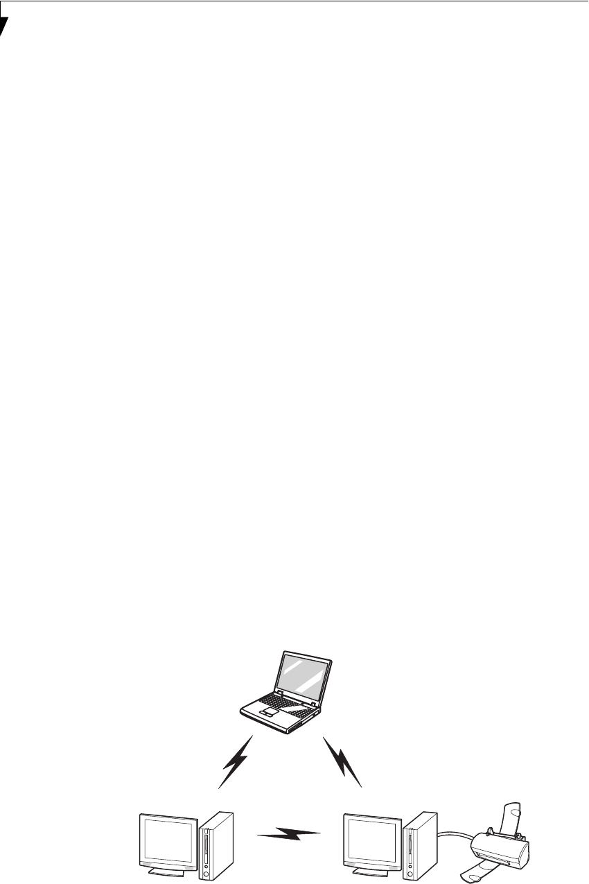
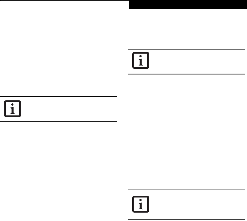
Ad Hoc Mode (See Figure A-1)
“Ad Hoc Mode” refers to a type of wireless network that
involves connecting multiple computers without the use
of an Access Point. Network connectivity between
computers can be established using only wireless LAN
cards in a peer-to-peer fashion.
Ad Hoc networks are an easy and inexpensive method
for establishing network connectivity between multiple
computers.
In Ad Hoc mode, you can use Microsoft Network func-
tions, such as File and Print Sharing to share folders,
printers, or other peripheral devices, and exchange files
with other computers.
To use Ad Hoc Mode, you must set the same SSID and
the same encryption key for all the computers that are
connected. Communication between computers in an
Ad Hoc network will occur provided they are within
each other’s RF coverage area.
Figure A-1. Ad Hoc Mode Network
available for Fujitsu mobile computers. This manual
describes the basic operating prodecures for the
Wireless LAN (referred to as the "wireless module" in
this manual) and how to set up a wireless LAN network.
Before using this wireless module, read this manual
carefully to ensure correct operation of the device. Keep
this manual in a safe place for reference while using the
wireless module.
is the Intel PROSet wireless LAN; if your system is a
T3010D model, your wireless module is the Atheros
wireless LAN.
53
Wireless LAN User’s Guide
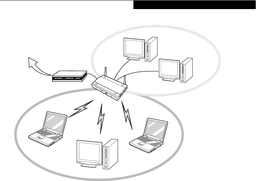
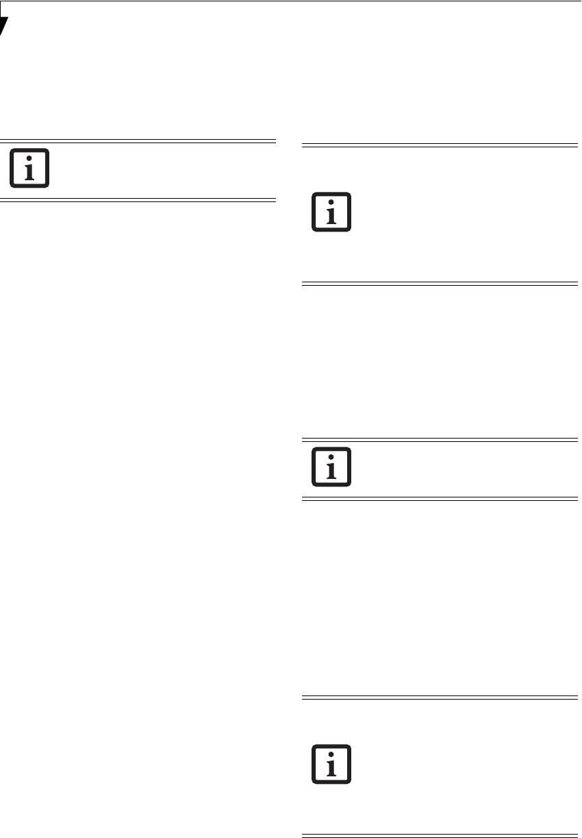
Access Point (Infrastructure) Mode (See Figure A-2)
If a number of computers are connected simultaneously
in the Ad Hoc mode, the transfer rate may be reduced,
communications may become unstable, or the network
connection could fail. This is because all wireless LAN
cards are using the same radio frequency in the network.
To improve this situation, you can use a wireless LAN
access point, which is sold separately. The wireless LAN
network is in the “Access Point mode” when it uses an
access point, and such a connection is called the “Access
Point Network” or “Infrastructure Network”.
By using an access point, you can set and use a different
communication channel for each network group. Each
channel is given a different radio frequency, and it
eliminates the collision of communications and provides
a more stable communications environment.
How to Handle This Wireless Module
The Integrated Wireless LAN device is already installed in
your mobile computer. Under normal circumstances, it
should not be necessary for you to remove or re-install it.
The wireless LAN has been configured to support the
operating system with which your system shipped.
FOR BETTER COMMUNICATIONS
This personal computer may not operate properly due to
the operating environment. It is highly recommended
that you observe the following precautions when using
your wireless LAN module:
■For optimum wireless communications, it recom-
mended that operation of the wireless LAN module
occur within 25 meters of the Access Point. Wireless
range is dependent on a multitude of factors including
number of obstructions, walls, type of construction
material, reflective objects, etc.
■If the computer is unable to communicate properly,
change the channel to be used or the installation loca-
tion. During the use of a microwave oven or other
equipment generating strong high-frequency energy, in
particular, the personal computer may be highly sus-
ceptible to the energy and unable to communicate
properly.
■Broadcast stations or wireless communication equip-
ment that operate in the 2.4GHz or 5GHz RF Fre-
quency band may interfere with the operation of the
wireless LAN module. Increasing of transmit power or
relocating Access Points may be necessary to combat
the effects of the interference.
Figure A-2. Access Point (Infrastructure) Mode Network
Internet ADSL modem,
cable modem,
or similar
Wired LAN
Wireless LAN
Access Point*
* An optional hub for a wired
LAN may be required depending
upon the type of access point used.
54
STOPPING TRANSMISSION
To use this product inside hospitals, clinics, or airplanes,
or in other places where the use of electronic equipment
is regulated, stop the transmission of radio waves from
the wireless LAN beforehand.
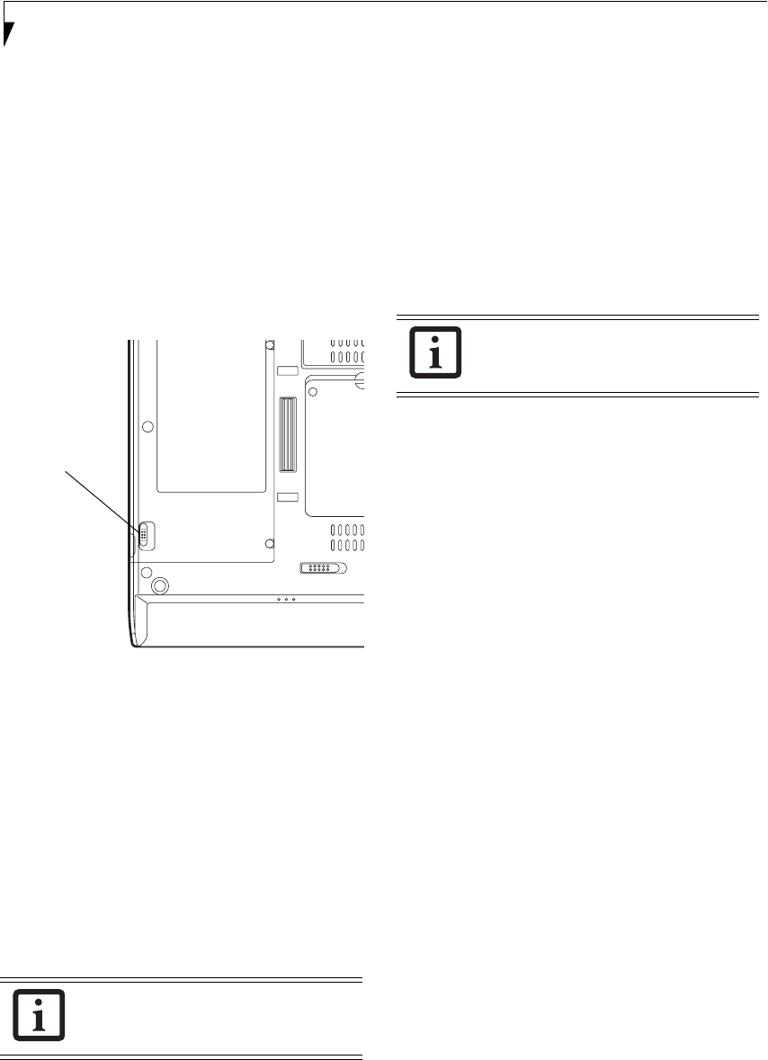
Deactivation using the wireless switch
The transmission of radio waves from the wireless LAN
can be stopped by setting the wireless switch to the Off
position. Note that the wireless LAN On/Off switch has
no effect on non-wireless LAN models.
(See Figure 3 for Wireless LAN switch location.)
Figure A-3. Wireless LAN On/Off Switch
Deactivation using Windows
Intel PROSet Wireless LAN:
1. Click [Start] --> [(All) Programs] --> [Intel Net-
work Adapters] --> [Intel(R) PROSet]. The
Intel(R) PROSet window will be displayed.
2. Click the General tab.
3. Select [Off] for the wireless communications
Switch Radio: function, and then click the [OK]
button. Wireless communications on/off switching
will be deactivated and the transmission of radio
waves from the wireless LAN will be stopped.
Atheros Wireless LAN
1. Click [Start] --> [Control Panel] --> [Atheros Cli-
ent Utility]. The Atheros Wireless Configuration
Utility window will be displayed.
2. Click the Wireless Networks tab.
3. Click the [Enable Radio] box to clear it, then click
the [OK] button. Wireless communications on/off
switching will be deactivated and the transmission
of radio waves from the wireless LAN will be
stopped.
STARTING TRANSMISSION
To communicate using the wireless LAN function, set
the computer to a status from which it can transmit, as
follows:
Intel PROSet Wireless LAN:
1. Set the wireless switch to the On position.
2. Click [Start] --> [(All) Programs] --> [Intel Net-
work Adapters] --> [Intel(R) PROSet]. The
Intel(R) PROSet window will be displayed.
3. Click the [General] tab if it is not already selected.
4. Select [ON] for the Switch radio: function, then
click [OK]. Wireless communications on/off
switching will be activated and the transmission of
radio waves will be restarted.
Atheros Wireless LAN:
1. Click the Wireless Network Connection icon in the
system tray at the lower right of your screen.
2. Click [Enable Radio]. The radio will be turned on.
Access Point Mode: Transmission is enabled.
Ad Hoc Mode: Restart your computer to enable the
radio.
To restart transmission, select [On] for the
wireless communications Switch Radio:
function, and then click the [OK] button.
Wireless LAN
On/Off
Switch
To restart transmission, check the [Enable
Radio] checkbox to select it., then click the
[OK] button.

55
Wireless LAN User’s Guide
Connecting the WLAN
FLOW OF OPERATIONS
The wireless LAN connection procedure contained in
this section is outlined below.
1. Make sure the mobile computer is ready for the
transmission of radio waves from the wireless LAN.
For further details, see (See Starting Transmission
on page 54 for more information.).
2. Assign the parameters required for wireless LAN
connection. (See Preparation for wireless LAN con-
nection on page 55 for more information.).
■Configure network name (SSID).
■Configure wireless LAN security parameters as
appropriate (e.g., WEP, TKIP, 802.1x/EAP).
3. Perform setting operations relating to network con-
nection. (See Connection to the network on page 57
for more information.)
■Specify TCP/IP as the protocol, and confirm the name
of the work group and other settings.
■Enter the data required for file/printer sharing on the
network. Perform this operation as required.
■For access point (or “infrastructure”) connection,
configure the wireless module with appropriate
parameters required to associate to the access point
network.
■Verify that you are able to connect your computer to
the network.
PREPARATION FOR WIRELESS LAN
CONNECTION
This section explains the preparations required to use
the wireless LAN when using the Windows XP Wireless
Zero Configuration Tool. Configuration can also be
accomplished using the wireless module (Intel or
Atheros) configuration utility.
Assigning parameters
Enter the network name (SSID), the network key, and
other data required for wireless LAN connection. If there
is the administrator of the network, contact the network
administrator for data settings.
1. Make sure the Wireless LAN switch is switched on.
2. Click the [Start] button first and then [Control
Panel].
3. If the Control Panel is in Category view, switch to
Classic view by clicking “Switch to Classic View”
under Control Panel the left frame. (If you are
already in Classic view, “Switch to Category View”
will be displayed instead.)
4. Double-click the Network Connections icon. A list
of currently installed networks will be displayed.
5. Right-click [Wireless Network Connection] in the
list, and then click [Properties] in the menu dis-
played. The [Wireless Network Connection Proper-
ties] window will be displayed.
6. Click the [Wireless Networks] tab.
7. Click [Refresh], then choose the correct SSID from
the [Available Networks] window. Click [Config-
ure] and proceed to step 7. If the SSID of your
access point does not appear in the list, click [Add].
The [Wireless Network Properties] window will be
displayed.
8. Select the Association tab if it is not already
selected.
9. Enter the information required for connection to
the wireless LAN.
a. Enter the network name (SSID). (i.e., Enter the
name of the desired network in less than 33
ASCII characters).
■To use access point (infrastructure) con-
nection, refer to the access point manual
for the access point-setting procedure.
■You do not need to set the channel
when using access point (infrastructure)
mode. Channel selection is controlled by
the access point. In ad hoc networks,
channel selection defaults to channel 11;
however, channel selection can be man-
ually changed if desired. This can be
accomplished only when using the client
utility.
If it is necessary to change the channel,
change the setting of the access point.
For the setting procedure, refer to the
manual of the access point.
56
For ad hoc connection: Assign the same network
name to all the personal computers to be
connected.
For access point (infrastructure) connection:
Assign the appropriate SSID. The SSID must be
identical to the SSID of the access point. Refer to
the access point manual, or contact your network
administrator.
b. For ad hoc connection, check the following field.
For access point (infrastructure) connection,
clear the check mark for the following field:
[This is a computer-to-computer (ad hoc) net-
work; wireless access points are not used.]
10. Enter the WEP key for encoding communications
data.
a. Check the [Data encryption (WEP enabled)]
check box
For ad hoc connection: Clear the check mark
from the [Network Authentication (Shared
mode)] check box.
For access point (infrastructure) connection: If
the access point to be accessed is configured for
shared-key authentication, check the [Network
Authentication (Shared mode)] check box.
For open-system authentication, clear the check
mark. For access point setting, refer to the man-
ual of the access point.
b. Clear the check mark from the [The key is
provided for me automatically] check box.
c. Enter data in [Network Key]. Depending on the
number of entered characters or digits, whether
the key is an ASCII character code or a hexadec-
imal code will be identified automatically.
Use five or thirteen characters to enter the key
in the ASCII character code format. The char-
acters that can be used as the “network key” are
as follows: 0 - 9, A - Z, _ (underscore), or,
Use 10 or 26 characters to enter the key in the
hexadecimal character code format. The char-
acters that can be used as the “network key” in
this case are as follows: 0- 9, A - Z, a - f
For ad hoc connection: Assign the same net-
work key to all the personal computers to be
connected.
For access point (infrastructure) connection:
Assign the identical network key that is pro-
grammed into the access point. For this set-
ting, refer to the access point manual or
contact your network administrator.
d. Confirm the Network key by re-entering the
same data in the [Confirm network key:] field.
e. Make sure that [Key index (advanced)] is set to
“1”. (Any value from “1” to “4” can be assigned
to [Key index (advanced)]. “1” is usually
assigned, however).
11. Click the [Authentication] tab and then verify the
settings of [Enable network access control using
IEEE 802.11x].
For internal use at an organization such as a com-
pany, when access by wireless LAN clients is to be
limited using IEEE 802.11x authentication, check
the [Enable network access control using IEEE
802.11x] check box.
For home use, clear the check mark from [Enable
network access control using IEEE 802.11x].
For the setting method relating to IEEE 802.11x
authentication, refer to the manual of the access
point which you are using.
12. After completion of setting operations, click the
[OK] button. Processing will return to the [Wire-
less Network Connection Properties] window.
13. Verify that the network name entered in step 7
above is added in [Preferred Networks], and then
click the [OK] button.
14. Close the [Wireless Network] window.
It is strongly recommended that you enter
the network key for encoding
communications data. If the network key
is not entered, since the network can be
accessed from all personal computers
containing the wireless LAN function,
there is the danger of your data being
stolen or damaged by other users.
In [Preferred Networks], register only the
desired connection settings.
57
Wireless LAN User’s Guide
CONNECTION TO THE NETWORK
This section explains connection to the network.
If there is an administrator of the network, contact the
network administrator for data settings.
Setting the network
Perform the “Setting TCP/IP” and “Confirming the
computer and work group names” operations required for
network connection.
Setting TCP/IP
1. Click the [Start] button first and then [Control
Panel].
2. If the Control Panel is in Category view, switch to
Classic view by clicking “Switch to Classic View”
under Control Panel the left frame. (If you are
already in Classic view, “Switch to Category View”
will be displayed.)
3. Double-click [Network Connections]. A list of cur-
rently installed networks will be displayed.
4. Right-click [Wireless Network Connection] in the
list, and then click [Properties] in the menu dis-
played. The [Wireless Network Connection Proper-
ties] window will be displayed.
5. Click the [General] tab if it is not already selected.
6. Click [Internet Protocol (TCP/IP] and then click
[Properties]. The [Internet Protocol (TCP/IP)
Properties] window will be displayed.
7. Set the IP address as follows:
■For ad hoc connection: Select [Use the following
IP address:] and then enter data for [IP address]
and [Subnet mask]. See page 66 for IP address
setting.
■For access point (infrastructure) connection: If
your network uses DHCP, select [Obtain an IP
address automatically] and [Obtain DNS server
address automatically]. If your network uses static
IP addresses, consult with your network adminis-
trator for the correct IP address settings.
8. Click the [OK] button. Processing will return to the
[Wireless Network Connection Properties] window.
9. Click the [OK] button.
10. Close the [Network Connection] window.
Following this operation, confirm the names of the
computer and the workgroup as follows.
Confirming the computer and work group names
1. Click the [Start] button, then [Control Panel].
2. If the Control Panel is in Category view, switch to
Classic view by clicking “Switch to Classic View”
under Control Panel the left frame. (If you are
already in Classic view, “Switch to Category View”
will be displayed.)
3. Double-click the [System] icon. The [System Prop-
erties] window will be displayed.
4. Click the [Computer Name] tab.
5. Confirm the settings of [Full computer name:] and
[Workgroup:].
a. The setting of [Full computer name:] denotes the
name for identifying the computer. Any name
can be assigned for each personal computer.
Enter the desired name in less than 15 ASCII
character code format. Identifiability can be
enhanced by entering the model number, the
user name, and other factors.
b. [Workgroup name] is the group name of the
network. Enter the desired name in less than 15
ASCII character code format.
For ad hoc connection: Assign the same network
name to all personal computers existing on the
network.
For access point (infrastructure) connection:
Assign the name of the work group to be
accessed.
6. Click the [OK] button. If a message is displayed
that requests you to restart the personal computer,
click [Yes] to restart the computer.
Setting the sharing function
Set the sharing function to make file and/or printer sharing
with other network-connected personal computers valid.
To change the setting of the IP address,
you need to be logged in from Windows
as an administrator.
To modify the computer name and/or the
work group name, you need to be logged
in from Windows as an administrator.
To change the name, click [Change] and
then proceed in accordance with the
instruction messages displayed on the
screen.
58
This operation is not required unless the sharing func-
tion is to be used.
The folder and printer for which the sharing function
has been set will be usable from any personal computer
present on the network.
Setting the Microsoft network-sharing service
1. Click the [Start] button first and then [Control
Panel].
2. If the Control Panel is in Category view, switch to
Classic view by clicking “Switch to Classic View”
under Control Panel the left frame. (If you are
already in Classic view, “Switch to Category View”
will be displayed.)
3. Double-click [Network Connections]. A list of cur-
rently installed networks will be displayed.
4. Right-click [Wireless Network Connection] in the
list, and then click [Properties] in the menu dis-
played. The [Wireless Network Connection Proper-
ties] window will be displayed.
5. If [File and Printer Sharing for Microsoft Net-
works] is displayed, proceed to step 6. If [File and
Printer Sharing for Microsoft Networks] is not dis-
played, skip to step 7.
6. Make sure that the [File and Printer Sharing for
Microsoft Networks] check box is checked, and
then click the [OK] button. Skip to “Setting file-
sharing function”.
7. Click [Install]. The [Select Network Component
Type] window will be displayed.
8. Click [Service], then click the [Add] button. The
[Select Network Service] window will be displayed.
9. Click [File and Printer Sharing for Microsoft Net-
works] and then click the [OK] button. Processing
will return to the [Wireless Network Connection
Properties] window, and [File and Printer Sharing
for Microsoft Networks] will be added to the list.
10. Click the [Close] button.
Setting the file-sharing function
The procedure for setting the file-sharing function
follows, with the “work” folder in drive C: as an
example.
1. Click the [Start] button first and then [My Com-
puter].
2. Double-click [Local disk (C:)].
3. Right-click the “work” folder (or whichever folder
you want to share), and then click [Sharing and
Security...] in the menu displayed. The [Folder
Name Properties] window will be displayed.
4. Click [Sharing] if it isn’t already selected.
5. Click the link stating “If you understand the secu-
rity risks, but want to share files without running
the wizard, click here”.
6. Click “Just enable file sharing” and click [OK].
7. Check the [Share this folder on the network] check
box.
8. Click the [OK] button. The folder will be set as a
sharable folder, and the display of the icon for the
“work.” folder will change.
Setting the printer-sharing function
1. Click the [Start] button first and then [Printers and
FAX]. A list of connected printers will be displayed.
2. Right-click the printer for which the sharing func-
tion is to be set, and then click [Sharing] in the
menu displayed. The property window correspond-
ing to the selected printer will be displayed.
3. Click the [Sharing] tab.
4. Click [Share this printer].
To share a file and/or the connected
printer, you need to be logged in as an
administrator.
Setting the file-sharing function for the file
which has been used to execute Network
Setup Wizard is suggested on the screen.
For the wireless LAN, however, since
security is guaranteed by entry of the
network name (SSID) and the network
key, the steps to be taken to set the file-
sharing function easily without using
Network Setup Wizard are given below.
To specify the corresponding folder as a
read-only folder, select the [Read only]
checkbox under the General tab.
Setting the printer-sharing function when
Network Setup Wizard has been executed
is suggested on the screen. For the wireless
LAN, however, since security is guaranteed
by entry of the network name (SSID) and
the network key, the steps to be taken to
set the printer-sharing function without
using Network Setup W izard are laid down
below.

59
Wireless LAN User’s Guide
5. Enter the sharing printer name in [Share name].
6. Click the [OK] button.
Confirming connection
After you have finished the network setup operations,
access the folder whose sharing has been set for other
personal computers. Also, confirm the status of the radio
waves in case of trouble such as a network connection
failure.
Connecting your personal computer to another
personal computer
1. Click [Start] first and then [My Computer]. The
[My Computer] window will be displayed in the left
frame.
2. Click [My Network Places] in the “Other Places”
list. The window [My Network Places] will be dis-
played.
3. Click [View workgroup computers] under Network
Tasks in the left frame.
4. Double-click the personal computer to which your
personal computer is to be connected. The folder
that was specified in “Setting the file-sharing func-
tion” on page 58 will be displayed.
5. Double-click the folder to be accessed.
Confirming the status of the radio
Intel PROSet Wireless LAN:
1. Click [Start] -> [All Programs] -> [Intel Network
Adapters] -> [Intel(R) PROSet]. The [Intel(R)
PROSet] window will be displayed.
2. Click the [General] tab and confirm radio status in
the window displayed. The current connection sta-
tus will be displayed.
■Signal Quality
The quality of the signals is displayed on a graph.
■Network name (SSID)
The connected network name (SSID) is displayed.
■Profile name
“<No profile>” is displayed.
■Mode
If access point (infrastructure) connection is in
use, “Infrastructure (AP)” will be displayed. If ad
hoc connection is in use, “Ad hoc (Peer-to-peer)”
will be displayed.
■Security
Displays the encryption type currently used by
the radio.
■Speed
Displays the current data rate used by the radio to
transmit and receive data.
■Band (Frequency)
The current operating frequency band is
displayed. When communication is possible,
“802.11b (2.4 GHz)” is displayed.
■Channel
The channel number currently being used for the
communications is displayed.
If connection cannot be made to the network or if you
want to check for normal connection, see “Trouble-
shooting” on page 62.
Atheros Wireless LAN:
1. Right-click the Atheros icon in the lower right cor-
ner of the screen.
2. Click [Open Client Utility]. The Atheros Wireless
Configuration Utility window opens.
3. Contained within the Current Status tab and
Advanced Current Status, you will find the current
operating status of the radio. (When the radio is
turned off or the computer is not yet connected,
some of the conditions will not be displayed.)
■Profile Name
The current configuration profile is displayed.
■Network Type - Configured Network Type
[Access Point] or [AdHoc] will be displayed.
■Current Mode
Indicates the frequency and data rate currently
used by the radio.
■Current Channel
The channel number currently used by the radio.
■Link Status
Displays the current connected state of the
WLAN module.
■Encryption Type
Displays the encryption type currently used by
the radio.
In the case of access point (infrastructure)
connection, enter the necessary data for
the access point before confirming
connection. Refer to the manual of the
access point for the access point setup
procedure.

60
IP Address
Displays the current TCP/IP address assigned to
the WLAN adapter.
Country
The country with the country code for which the
radio is configured.
Transmit Power Level
Displays the current transmit power level of the
radio.
Network Name (SSID)
Displays the Network Name (SSID) currently
used by the radio.
Power Save Mode
Displays the configured Power Save Mode
currently used by the radio. [Off], [Normal], or
[Maximum] will be displayed.
BSSID
Displays the Basic Service Set Identifier. This is
typically the MAC address of the Access Point or
in the case of AdHoc networks, is a randomly
generated MAC address.
Frequency
Displays the center frequency currently being
used by the radio.
Transmit Rate
Displays the current data rate used by the radio
to transmit data.
Receive Rate
Displays the current data rate used by the radio
to receive data.

61
Wireless LAN User’s Guide
Other settings
SETTING OF POWER-SAVING FUNCTION
You can set the power-saving function of wireless LAN.
Default setting is auto-setting. In case of using the power-
saving function, manually control the communication
performance.
Intel PROSet Wireless LAN:
1. Click [Start] -> [(All) Programs] -> [Intel Network
Adapters] -> [Intel(R) PROSet]. The Intel(R)
PROSet window will be displayed.
2. Click the [Adapter] tab.
3. Click the [Configure] button in [Power settings].
The [Power settings] window will be displayed.
4. Select [Manual], and adjust the bar to set the power-
saving function.
Setting of transmission power during ad hoc
connection
By controlling the transmission power during ad hoc
connection, you can broaden or narrow the communica-
tion range. This setting is only effective during ad hoc
connection. It will be ineffective during access point
connection.
Intel PROSet Wireless LAN:
1. Click [Start] -> [(All) Programs] -> [Intel Network
Adapters] -> [Intel(R) PROSet]. The Intel(R)
PROSet window will be displayed.
2. Click the [Adapter] tab.
3. Click the [Configure] button in [Power settings].
The [Power settings] window will be displayed.
4. Adjust the “Transmission Power (Ad Hoc)” bar to
set the transmission power.
Setting of channels during ad hoc connection
You can set channels during ad hoc connection. Channel
11 is set by default. When connecting to an existing ad
hoc network, no channel setting will be effective.
This setting is only effective during ad hoc connection; it
will be ineffective during access point connection.
Intel PROSet Wireless LAN:
1. Click [Start] -> [(All) Programs] -> [Intel Network
Adapters] -> [Intel(R) PROSet]. The Intel(R)
PROSet window will be displayed.
2. Click the [Adapter] tab.
3. Click the [Configure] button in [Ad hoc settings].
The [Ad hoc settings] window will be displayed.
4. Change channels during ad hoc connection by
selecting a new channel from the drop down list.
5. Click [OK].
Atheros Wireless LAN:
1. Click on the My Computer icon. Select [View sys-
tem information] from the left frame.
2. Select the Hardware tab and click [Device Manager].
3. Double-click “Atheros Wireless LAN Adapter”
under [Network Adapters].
4. In the Atheros Wireless LAN Adapter window, select
the Advanced tab.
5. Select IBSS Channel Number from the list, and
change the value from the [Value:] dropdown list to
the desired channel.
6. Click [OK].
When changing channels during ad hoc
connection, change the channel settings of
all connected computers with the same
Network name (SSID) at the same time.
After changing the channels, turn off all
computers and -- after they are all turned
off -- turn them back on.

62
Troubleshooting
Causes and countermeasures for troubles you may encounter while using your wireless LAN are described in the
following table.
Problem Possible Cause Possible Solution
Unavailable
network
connection
Incorrect network
name (SSID) or
network key
Ad hoc connection: verify that the network names (SSID’s) and network
keys (WEP) of all computers to be connected have been configured
correctly. SSID’s and WEP key values must be identical on each machine.
Access Point (Infrastructure) connection: set the network name (SSID)
and network key to the same values as those of the access point.
Set the Network Authentication value identically to that of the Access
Point. Please consult your network administrator for this value, if
necessary.
For the method of setting network authentication, refer to the following
pages:· “ Assigning parameters” on page 55·
Poor radio wave
condition Ad hoc connection: Retry connection after shortening the distance to
the destination computer or removing any obstacles for better sight.
Access Point (Infrastructure) connection: Retry connection after short-
ening the distance to the access point or removing any obstacles for
better sight.
To check the wave condition, refer to the following pages:· “ Confirming
the status of the radio waves” on page 59.·
Radio wave
transmission has
stopped
Check if the wireless switch is turned ON. Also verify “ Disable Radio” is
not checked in “ Network setting” window. Refer to “ Starting Transmis-
sion” on page 54.
The computer to be
connected is turned
off
Check if the computer to be connected is turned ON.
Active channel
duplication due to
multiple wireless
LAN networks
If there is any other wireless LAN network nearby, change channels to
avoid active channel duplication. For the method of checking active
channels, refer to the following pages:· “ Confirming the status of the
radio waves” on page 59·
No right of access to
the network to be
connected
Check if you have a right of access to the network to be connected with.
Incorrectly-
performed network
setting
Check the protocol, work group name or shared setting.
For the method of checking, refer to the following pages:· “ Connection
to the Network” on page 57.
Unmatched
[Network
authentication
(shared mode)]
settings in Windows
XP
If the setting of [Network authentication (shared mode)] is not matched
with that of access point or computer to be connected with, no commu-
nication can be established. Check the parameter setting.Refer to
“ Assigning parameters” on page 55.

63
Wireless LAN User’s Guide
Unavailable
network
connection
(continued)
It takes too long to
retrieve the network
and display the
connected
computers.
Retrieve computers as follow:
1. Click [Start] button, then click [Search].
2. Click [Computers or people].
3. Click [Computers on the network].
4. Input the name of computer to be connected with in [Computer
name] and click [Search].
5. Double-click the icon of connected computer.·
Incorrect setting of IP
address
Check the network setting.
“Setting the network” on page 57.
In case of using TCP/IP protocol, you can check IP address as follows:
1. Click [Start] -> [All programs] -> [Accessories] ->
[Command prompt].·
2. In [Command prompt] or [MS-DOS prompt] window, input
[IPCONFIG] command as follows, then press [Enter] key.
Example: In case of C drive being the hard disk:
C:\ipconfig [Enter]
Check that the IP address is correctly displayed:.
IP Address................: 10.0.1.3
Subnet Mask.............: 255.255.255.0
Default Gateway.........: 10.0.1.1
When IP address is displayed as [169.254.XXX.YYY] or [0.0.0.0],
IP address is not correctly fetched from the access point. In that
case, restart the computer itself. If the display is still unchanged,
check the setting of TCP/IP.
If [Cable Disconnected] or [Media Disconnected] is displayed
without showing IP address, check the setting of network name
(SSID) and network key. Also, set the network authentication
according to the access point.
Communication
is disconnected
soon after
connection to
the access point
Access control may
be disabled
Check the setting of “Enable network access control using IEEE
802.1X”.Refer to “Assigning parameters” on page 55.
When restricting the access of wireless LAN clients using IEEE802.1X
authentication, put a check mark on “Enable network access control
using IEEE 802.1X”.
When using at home, remove a check mark on “Enable network access
control using IEEE802.1X”.
For the method of setting related with IEEE802.1X authentication, refer
to the access point manual.
Authentication
method may have
been entered
incorrectly
Re-enter your WEP key and verify that your authentication method
(Open or Shared) is correct.
Problem Possible Cause Possible Solution

64
Wireless LAN Glossary
Access point
A designation of wireless LAN network configurations.
It indicates a form of communication using an Access
Point. For details, refer to “access point connection” on
page52.
Ad hoc
A designation for wireless LAN network configuration.
It indicates a form of communication limited to those
personal computers which have wireless LAN function.
For details, refer to “Ad hoc connection” on page52.
Channel
The frequency band of wireless LAN to be used in
communications over wireless LAN or at the access
point.
DHCP (Dynamic Host Configuration Protocol)
A protocol used for automatically fetching communica-
tion parameters such as IP addresses. The side which
assigns IP address is called DHCP server and the side
that is assigned it is called DHCP client.
DNS (Domain Name System)
A function that controls the correspondence of IP
addresses assigned to a computer with the name. Even
for those computers whose IP addresses are unknown, if
their names are known, it is possible to communicate
with them.
IEEE802.11a
One of the wireless LAN standards prescribed by the
802.11 committee in charge of establishing standards of
LAN technology in IEEE (Institute of Electrical and
Electronic Engineers). It allows communications at the
maximum speed of 54 Mbps by using a 5GHz band
which can freely be used without radio communication
license.
IEEE802.11b
One of the wireless LAN standards prescribed by the
802.11 committee in charge of establishing standards of
LAN technology in IEEE (Institute of Electrical and
Electronic Engineers). It allows communications at the
maximum speed of 11Mbps by a band of 2.4 GHz (ISM
band) which can freely be used without radio communi-
cation license.
IP address
An address used by computers for communicating in
TCP/IP environment. IP addresses have global and
private addresses. A global address is a unique address in
the world. A private address is a unique address within a
closed network.
LAN (Local Area Network)
An environment connecting computers within a rela-
tively small range, such as the same floor and building.
MAC address (Media Access Control Address)
A physical address inherent to a network card. For
Ethernet, the top three bytes are controlled/assigned as a
vendor code. The remaining three bytes comprise the
code uniquely (to avoid duplication) controlled by each
vendor. As a result, there is no Ethernet card with the
same physical address in the world. In Ethernet, the
frame transmission/reception is performed based on this
address.
MTU (Maximum Transmission Unit)
The maximum size of data which can be transmitted at
one time in networks including the Internet. In an envi-
ronment whose maximum size of data is too large to
correctly receive data, normal communications can be
restored by setting the size of MTU to a smaller value.
Network authentication
The method of authentication performed by wireless
LAN clients to connect with the access point. There are
two types: open system authentication and shared key
authentication. The type of authentication must be set
to each client and also coincide with the setting of access
point with which to communicate. Network authentica-
tion is sometimes called authentication mode.
Network key
Data that is used for encrypting data in data communi-
cation. The personal computer uses the same network
key both for data encryption and decryption, therefore,
it is necessary to set the same network key as the other
side of communication.
Network name (SSID: Service Set Identifier)
The network name is a unique identifier attached to the
WLAN packet header that acts as a password when the
client attempts to connect to a WLAN. The SSID differ-
entiates one WLAN from another so all WLAN devices
attempting to connect to a specific WLAN must use the
same SSID.SSID’s are transmitted in cleartext, thus
supplying no security to the WLAN.

65
Wireless LAN User’s Guide
Open system authentication
An 802.11 wireless LAN authentication method. Open
System does not exchange any key or other information,
it is a simple request by the mobile station to be authenti-
cated without verifying identity.
PPPoE (Point to Point Protocol over Ethernet)
A method of allowing the authentication protocol
adopted in telephone line connection (PPP) to be used
over an Ethernet.
Protocol
A procedure or rule of delivering data among computers.
Ordered data communication is allowed by making all
conditions required for communication including the
method of data transmission/reception and actions upon
communication errors into procedures.
Shared key authentication
An 802.11 wireless LAN authentication method. When a
client attempts to associate to an access point, the access
point will send a challenge to the client. The client
encrypts the challenge with the network key and sends it
back to the access point. If the access point can decrypt
the challenge, then authentication has succeeded.
SSID (Service Set Identifier)
See “Network name”
Subnet mask
TCP-IP network is controlled by being divided into
multiple smaller networks (subnets). IP address consists
of the subnet address and the address of each computer.
Subnet mask defines how many bits of IP address
comprise the subnet address. The same value shall be set
among computers communicating with each other.
TCP/IP (Transmission Control Protocol/Internet
Protocol)
A standard protocol of the Internet.
Wi-Fi
Short for “Wireless Fidelity”. A term meant to be used
generically when referring to any type of 802.11 network,
whether 802.11b, 802.11a, 802.11g, etc.

66
IP address information
If IP address is unknown, set IP address as follows:
If you have an access point (DHCP server) on the
network, set the IP address as follows:
[Obtain an IP address automatically]
If the IP address is already assigned to the computer in
the network, ask the network administrator to check the
IP address to be set for the computer.
If no access point is found in the network:
An IP address is expressed with four values in the range
between 1 and 255.
Set the each computer as follows: The value in paren-
theses is a subnet mask.
<Example>
Computer A: 192.168.100.2 (255.255.255.0)
Computer B: 192.168.100.3 (255.255.255.0)
Computer C: 192.168.100.4 (255.255.255.0)
:
:
Computer X: 192.168.100.254 (255.255.255.0)
IP addressing is much more complicated
than can be briefly explained in this
document. You are advised to consult with
your network administrator for additional
information.
A DHCP server is a server that
automatically assigns IP addresses to
computers or other devices in the network.
There is no DHCP server for the AdHoc
network.

67
Wireless LAN User’s Guide
Specifications
* “Wi-Fi based” indicates that the interconnectivity test of the organization which guarantees the interconnectivity of
wireless LAN (Wi-Fi Alliance) has been passed.
** Encryption with network key (WEP) is performed using the above number of bits, however, users can set 40 bits/104
bits after subtracting the fixed length of 24 bits.
*** The maximum number of computers that can be supported by an Access Point is highly variable, and can be affected
by such factors as application bandwidth utilization, broadcast packet traffic, type of applications used, etc. The
number of 10 provided by this document is meant only as a guideline and not a limitation of the technology.
Item Specification
Type of network Conforms to IEEE 802.11a/802.11b/g (Wi-Fi based)*
Transfer rate (Automatic switching)
54 Mbps maximum data rate
Active frequency 802.11b/g: 2400~2473 MHz
802.11a: 4900 ~ 5850 MHz
Number of channels 802.11a: 8 independent channels
802.11b/g: 11 channels, 3 non-overlapping channels
Security Network name (SSID)
Network key (64 bits/128 bits)**
WPA 1.0 compliant
Supports TKIP and WEP encryption algorithms
802.1x/EAP
Maximum recommended number of computers to be
connected over wireless LAN (during ad hoc
connection)
10 units or less ***