Fujitsu Client Computing WL0033 LifeBook P Series w/WM3B2915ABG 11ABG WLAN User Manual P Series
Fujitsu Limited LifeBook P Series w/WM3B2915ABG 11ABG WLAN P Series
Contents
- 1. Users Manual
- 2. Revised Users Manual1
- 3. Revised Users Manual2
Revised Users Manual1
Copyright
Copyright & Trademark Information
Fujitsu Computer Systems Corporation has made every
effort to ensure the accuracy and completeness of this
document. However, as ongoing development efforts are
continually improving the capabilities of our products,
we cannot guarantee the accuracy of the contents of this
document. We disclaim liability for errors, omissions, or
future changes.
Fujitsu, the Fujitsu logo, and LifeBook are registered
trademarks of Fujitsu Limited.
Microsoft, MS-DOS, and Windows are either registered
trademarks or trademarks of Microsoft Corporation in
the United States and/or other countries.
Atheros and Super AG are registered trademarks of
Atheros Communications, Inc.
Adobe, Acrobat, and Acrobat Reader are either regis-
tered trademarks or trademarks of Adobe Systems
Incorporated in the United States and/or other coun-
tries.
Realtek is a trademark of Realtek Semiconductor Corpo-
ration.
All other trademarks mentioned herein are the property
of their respective owners.
© Copyright 2005 Fujitsu Computer Systems Corpora-
tion. All rights reserved. No part of this publication may
be copied, reproduced, or translated, without prior
written consent of Fujitsu Computer Systems Corpora-
tion. No part of this publication may be stored or trans-
mitted in any electronic form without the written
consent of Fujitsu Computer Systems Corporation.
B6FH-6861-01EN-00
WARNING
Handling the cord on this product or cords
associated with accessories sold with this
product, will expose you to lead, a
chemical known to the State of California
to cause birth defects or other
reproductive harm.
Wash hands after handling.
DECLARATION OF CONFORMITY
according to FCC Part 15
Responsible Party Name: Fujitsu Computer Systems Corporation
Address: 1250 E. Arques Avenue, MS 122
Sunnyvale, CA 94085
Telephone: (408) 746-6000
Declares that product: Model Configuration:
LifeBook P1510D Notebook
Complies with Part 15 of the FCC Rules.
This device complies with Part 15 of the FCC rules. Operations are subject to the following two conditions:
(1) This device must not be allowed to cause harmful interference, (2) This device must accept any interference
received, including interference that may cause undesired operation.
P Series.book Page 1 Wednesday, July 13, 2005 10:43 AM
LifeBook P Series Notebook
IMPORTANT SAFETY INSTRUCTIONS
This unit requires an AC adapter to operate. Use only UL
Listed Class 2 Adapters with an output rating of 16
VDC, with a current of 2.5 A.
AC adapter output polarity:
When using your notebook equipment, basic safety
precautions should always be followed to reduce the risk
of fire, electric shock and injury to persons, including
the following:
■Do not use this product near water for example, near
a bathtub, washbowl, kitchen sink or laundry tub, in a
wet basement or near a swimming pool.
■Avoid using the modem during an electrical storm.
There may be a remote risk of electric shock from
lightning.
■Do not use the modem to report a gas leak in the
vicinity of the leak.
■Use only the power cord and batteries indicated in
this manual. Do not dispose of batteries in a fire. They
may explode. Check with local codes for possible
special disposal instructions.
■To reduce the risk of fire, use only No. 26 AWG or
larger UL Listed or CSA Certified Telecommunication
Line Cord.
SAVE THESE INSTRUCTIONS
For Authorized Repair Technicians Only
System Disposal
+
Danger of explosion if Lithium (clock) bat-
tery is incorrectly replaced. Replace only
with the same or equivalent type recom-
mended by the manufacturer. Dispose of
used batteries according to the manufac-
turer’s instruction.
For continued protection against risk of
fire, replace only with the same type and
rating fuse.
Hg
LAMP(S) INSIDE THIS PRODUCT
CONTAIN MERCURY AND MUST
BE RECYCLED OR DISPOSED OF
ACCORDING TO LOCAL, STATE, OR
FEDERAL LAWS.
P Series.book Page 2 Wednesday, July 13, 2005 10:43 AM

Table of Contents
Fujitsu LifeBook® P Series Notebook
Table of Contents
1
PREFACE
Preface
About This Guide . . . . . . . . . . . . . . . . . . . . . . . . .3
Fujitsu Contact Information . . . . . . . . . . . . . . . . .3
Warranty . . . . . . . . . . . . . . . . . . . . . . . . . . . . . . .3
2
GETTING TO KNOW
YOUR LIFEBOOK
Overview
Unpacking . . . . . . . . . . . . . . . . . . . . . . . . . . . . . .7
Optional Accessories . . . . . . . . . . . . . . . . . . . . . .7
Locating the Controls/Connectors
Front and Display Components . . . . . . . . . . . . . .9
Left-Side Panel Components . . . . . . . . . . . . . . .10
Right-Side Panel Components . . . . . . . . . . . . . .11
Rear Panel Components . . . . . . . . . . . . . . . . . . .12
Bottom Components . . . . . . . . . . . . . . . . . . . . .13
Status Indicators
Power Indicator . . . . . . . . . . . . . . . . . . . . . . . . .14
AC Adapter/Battery Charging Indicator . . . . . . .14
Battery Level Indicator . . . . . . . . . . . . . . . . . . . .14
Hard Drive Access Indicator . . . . . . . . . . . . . . . .14
NumLk Indicator. . . . . . . . . . . . . . . . . . . . . . . . .15
CapsLock Indicator. . . . . . . . . . . . . . . . . . . . . . .15
ScrLk Indicator . . . . . . . . . . . . . . . . . . . . . . . . . .15
Display Panel
Opening the Display Panel . . . . . . . . . . . . . . . . .16
Using the System as a Tablet . . . . . . . . . . . . . . .16
Adjusting Display Panel Brightness . . . . . . . . . . .17
Keyboard
Using the Keyboard . . . . . . . . . . . . . . . . . . . . . .18
Numeric Keypad. . . . . . . . . . . . . . . . . . . . . . . . .18
Windows Keys . . . . . . . . . . . . . . . . . . . . . . . . . .18
Cursor Keys . . . . . . . . . . . . . . . . . . . . . . . . . . . .18
Function Keys. . . . . . . . . . . . . . . . . . . . . . . . . . .19
LifeBook Application Panel
Changing Button Functions . . . . . . . . . . . . . . . .21
Quick Point/Touch Screen
Clicking . . . . . . . . . . . . . . . . . . . . . . . . . . . . . . .22
Double-Clicking . . . . . . . . . . . . . . . . . . . . . . . . .22
Dragging . . . . . . . . . . . . . . . . . . . . . . . . . . . . . .22
Quick Point Control Adjustment. . . . . . . . . . . . .23
Touch Screen . . . . . . . . . . . . . . . . . . . . . . . . . . .23
Volume Control
Controlling the Volume . . . . . . . . . . . . . . . . . . .25
3
USING YOUR LIFEBOOK
Power Sources
Connecting the Power Adapters . . . . . . . . . . . . .29
Starting Your LifeBook
Power On. . . . . . . . . . . . . . . . . . . . . . . . . . . . . .30
Boot Sequence . . . . . . . . . . . . . . . . . . . . . . . . . .30
BIOS Setup Utility. . . . . . . . . . . . . . . . . . . . . . . .30
Booting the System . . . . . . . . . . . . . . . . . . . . . .31
Registering Your LifeBook notebook. . . . . . . . . .31
Installing Click Me!. . . . . . . . . . . . . . . . . . . . . . .31
Power Management
Suspend/Resume Button . . . . . . . . . . . . . . . . . .32
Standby Mode . . . . . . . . . . . . . . . . . . . . . . . . . .32
Hibernate Mode . . . . . . . . . . . . . . . . . . . . . . . . .33
Display Timeout . . . . . . . . . . . . . . . . . . . . . . . . .33
P Series.book Page 3 Wednesday, July 13, 2005 10:43 AM

LifeBook P Series
Hard Disk Timeout . . . . . . . . . . . . . . . . . . . . . . . 33
Windows Power Management . . . . . . . . . . . . . . 33
Restarting the System. . . . . . . . . . . . . . . . . . . . . 33
Power Off . . . . . . . . . . . . . . . . . . . . . . . . . . . . . 34
4
USER-INSTALLABLE FEATURES
Lithium ion Battery
Recharging the Battery. . . . . . . . . . . . . . . . . . . . 37
Replacing the Battery . . . . . . . . . . . . . . . . . . . . . 38
Memory Upgrade Module
Installing Memory Upgrade Modules . . . . . . . . . 39
Removing a Memory Upgrade Module . . . . . . . 39
Checking the Memory Capacity . . . . . . . . . . . . . 40
Secure Digital Media
Inserting SD Cards . . . . . . . . . . . . . . . . . . . . . . . 41
Removing An SD Card . . . . . . . . . . . . . . . . . . . . 41
Compact Flash Cards
Inserting Compact Flash Cards . . . . . . . . . . . . . . 42
Removing Compact Flash Cards. . . . . . . . . . . . . 43
Port Replicator
Port Replicator Components. . . . . . . . . . . . . . . . 44
Attaching Port Replicator . . . . . . . . . . . . . . . . . . 44
Detaching Port Replicator. . . . . . . . . . . . . . . . . . 44
Device Ports
Modem (RJ-11) Jack . . . . . . . . . . . . . . . . . . . . . 46
Internal LAN (RJ-45) jack . . . . . . . . . . . . . . . . . . 46
Docking Port . . . . . . . . . . . . . . . . . . . . . . . . . . . 46
Universal Serial Bus Ports . . . . . . . . . . . . . . . . . . 46
Microphone Jack . . . . . . . . . . . . . . . . . . . . . . . . 46
Headphone Jack. . . . . . . . . . . . . . . . . . . . . . . . . 46
External Video Port . . . . . . . . . . . . . . . . . . . . . . 47
5
TROUBLESHOOTING
Troubleshooting
Identifying the Problem . . . . . . . . . . . . . . . . . . . 51
Specific Problems . . . . . . . . . . . . . . . . . . . . . . . . 51
Troubleshooting Table . . . . . . . . . . . . . . . . . . . . 52
Power On Self Test Messages . . . . . . . . . . . . . . 58
Modem Result Codes. . . . . . . . . . . . . . . . . . . . . 59
Restoring Your Pre-installed Software
Restoring the Factory Image . . . . . . . . . . . . . . . 60
Automatically Downloading Driver Updates. . . . 61
6
CARING FOR YOUR LIFEBOOK
Care and Maintenance
LifeBook P Series notebook . . . . . . . . . . . . . . . . 65
Keyboard . . . . . . . . . . . . . . . . . . . . . . . . . . . . . . 66
Batteries. . . . . . . . . . . . . . . . . . . . . . . . . . . . . . . 66
Floppy Disk Drive and Floppy Disks . . . . . . . . . . 66
Optional Optical Drive and Discs . . . . . . . . . . . . 67
CF Cards . . . . . . . . . . . . . . . . . . . . . . . . . . . . . . 67
7
SYSTEM SPECIFICATIONS
Specifications
Configuration Label . . . . . . . . . . . . . . . . . . . . . . 71
Physical Specifications . . . . . . . . . . . . . . . . . . . . 71
Processing Specifications . . . . . . . . . . . . . . . . . . 71
Memory/Storage Specifications . . . . . . . . . . . . . 71
Display Specifications. . . . . . . . . . . . . . . . . . . . . 71
Interface Specifications . . . . . . . . . . . . . . . . . . . 71
Power Specifications . . . . . . . . . . . . . . . . . . . . . 72
Environmental Specifications . . . . . . . . . . . . . . . 72
Agency Approval Specifications . . . . . . . . . . . . . 72
Additional Specifications . . . . . . . . . . . . . . . . . . 72
Regulatory Information . . . . . . . . . . . . . . . . . . . 73
8
GLOSSARY
Glossary. . . . . . . . . . . . . . . . . . . . . . . . . . . . . . . 77
P Series.book Page 4 Wednesday, July 13, 2005 10:43 AM

Table of Contents
APPENDIX A: INTEGRATED
WIRELESS LAN USER’S GUIDE
Before Using the Wireless LAN
Wireless LAN Modes Using this Device. . . . . . . .86
Wireless Network Considerations . . . . . . . . . . . .87
Deactivating the WLAN Device . . . . . . . . . . . . .87
Activating the WLAN Device . . . . . . . . . . . . . . .88
Configuration of the WLAN Device
Flow of Operations. . . . . . . . . . . . . . . . . . . . . . .89
Configuration Using Atheros Client Utility . . . . .89
Connection to the network. . . . . . . . . . . . . . . . .90
Troubleshooting the WLAN
Troubleshooting Table . . . . . . . . . . . . . . . . . . . .93
Wireless LAN Glossary
Glossary . . . . . . . . . . . . . . . . . . . . . . . . . . . . . . .94
IP address information
About IP Addresses . . . . . . . . . . . . . . . . . . . . . .96
WLAN Specifications
Specifications . . . . . . . . . . . . . . . . . . . . . . . . . . .97
APPENDIX B: USING THE
FINGERPRINT SWIPE SENSOR
Fingerprint Sensor Device
Introducing the Fingerprint Sensor Device . . . . 101
Getting Started. . . . . . . . . . . . . . . . . . . . . . . . .101
Installing OmniPass . . . . . . . . . . . . . . . . . . . . .101
User Enrollment . . . . . . . . . . . . . . . . . . . . . . . .102
Using OmniPass . . . . . . . . . . . . . . . . . . . . . . . .103
Configuring OmniPass . . . . . . . . . . . . . . . . . . .105
OmniPass Control Center. . . . . . . . . . . . . . . . .106
Troubleshooting . . . . . . . . . . . . . . . . . . . . . . . .107
P Series.book Page 5 Wednesday, July 13, 2005 10:43 AM

LifeBook P Series
P Series.book Page 6 Wednesday, July 13, 2005 10:43 AM

1
1
Preface
P Series.book Page 1 Wednesday, July 13, 2005 10:43 AM

2
LifeBook P Series Notebook
P Series.book Page 2 Wednesday, July 13, 2005 10:43 AM
3
Preface
Preface
ABOUT THIS GUIDE
The LifeBook® P Series notebook from Fujitsu
Computer Systems Corporation is a small yet powerful
convertible computer. It can be used either as a standard
notebook using keyboard input, or in tablet configura-
tion using pen input. It is powered by an Intel®
Pentium® M microprocessor, has a built-in color display
with a passive digitizer, and brings the computing power
of desktop personal computers (PCs) to a versatile
portable environment.
This manual explains how to operate your LifeBook P
Series notebook’s hardware and built-in system soft-
ware. Your notebook comes with the Windows® XP
operating system pre-installed.
Your LifeBook P Series notebook is a completely self-
contained unit with an active-matrix (TFT) color LCD
display. The notebook has a powerful interface that
enables it to support a variety of optional features.
Conventions Used in the Guide
Keyboard keys appear in brackets.
Example: [Fn], [F1], [Esc], [Enter] and [Ctrl].
Pages with additional information about a specific topic
are cross-referenced within the text.
Example: (See page xx.)
On screen buttons or menu items appear in bold.
Example: Click OK to restart your notebook.
DOS commands you enter appear in Courier type.
Example: Shutdown the computer?
FUJITSU CONTACT INFORMATION
Service and Support
You can contact Fujitsu Computer Systems Service and
Support the following ways:
■Toll free: 1-800-8Fujitsu (1-800-838-5487)
■Fax: 1-408-764-2724
■E-mail: 8fujitsu@us.fujitsu.com
■Web site:
http://www.computers.us.fujitsu.com/support
Before you place the call, you should have the following
information ready so that the customer support
representative can provide you with the fastest possible
solution:
■Product name
■Product configuration number
■Product serial number
■Purchase date
■Conditions under which the problem occurred
■Any error messages that have occurred
■Type of device connected, if any
Fujitsu Online
You can go directly to the online Fujitsu Product catalog
for your notebook. Go to Start -> Fujitsu Weblinks ->
LifeBook Accessories.
You can also reach Fujitsu Service and Support online by
going to Start -> Fujitsu Weblinks -> Fujitsu Service and
Support.
WARRANTY
Your LifeBook P Series notebook is backed by an
International Limited Warranty and includes toll-free
technical support. Check the service kit that came with
your notebook for warranty terms and conditions.
The information icon highlights
information that will enhance your
understanding of the subject material.
The caution icon highlights information
that is important to the safe operation of
your computer, or to the integrity of your
files. Please read all caution information
carefully.
The warning icon warns you about
possible hazards that can occur to you,
your system, or your files. Please read all
warning information carefully.
You must have an active internet
connection to use the online URL links.
P Series.book Page 3 Wednesday, July 13, 2005 10:43 AM

4
LifeBook P Series Notebook
P Series.book Page 4 Wednesday, July 13, 2005 10:43 AM

5
2
Getting to Know
Your LifeBook
P Series.book Page 5 Wednesday, July 13, 2005 10:43 AM

6
LifeBook P Series Notebook - Section Two
P Series.book Page 6 Wednesday, July 13, 2005 10:43 AM
7
Getting to Know Your Tablet PC
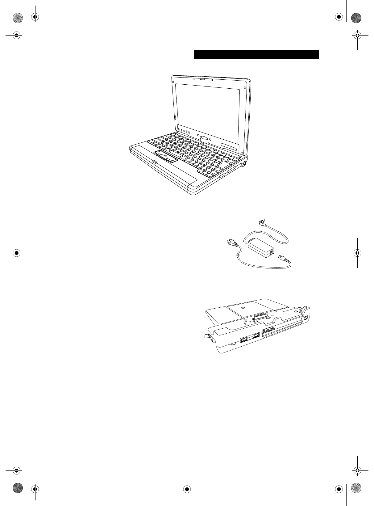
Figure 2-1. Fujitsu LifeBook P Series notebook
Overview
This section describes the components of your Fujitsu
LifeBook P Series notebook. We strongly recommend
that you read it before using your notebook, even if you
are already familiar with mobile computers.
UNPACKING
When you receive your LifeBook P Series notebook,
unpack it carefully, and compare the parts you have
received with the items listed below.
For a pre-configured model you should have:
■LifeBook P Series notebook (Figure 2-1)
■AC adapter with AC power cord (Figure 2-2)
■Phone/Modem (RJ-11) telephone cable
■Pen
■Pen tether
■Driver and Application Restore (DAR) CD
■Recovery CD
■Third-party Application CD
■Getting Started Guide
■User’s Guide (this document)
■International Limited Warranty Booklet
■Certificate of Authenticity
■Lithium ion battery (pre-installed)
You may also have one or more of the following devices
in the box, depending upon the configuration of your
system:
■Port Replicator (Figure 2-3)
■External USB Floppy Disk Drive
■Additional battery(s)
■Application CD(s) for third-party software
Figure 2-2. AC Adapter
Figure 2-3. Optional Port Replicator
OPTIONAL ACCESSORIES
A variety of optional accessories is available for use with
your LifeBook P Series notebook. For the latest list of
accessories available, be sure to frequently check the
Fujitsu Web site at: www.shopfujitsu.com. Refer to the
instructions provided with these accessories for details
on their use.
P Series.book Page 7 Wednesday, July 13, 2005 10:43 AM
8
LifeBook P Series Notebook - Section Two
Locating the Controls and Connectors
Connectors and peripheral interfaces on the LifeBook P
Series notebook and the optional port replicator allow
you to connect a variety of devices. Specific locations are
illustrated in Figures 2-4 through 2-8. The table below
provides a short description of each icon on the Life-
Book P Series notebook. Each of the icons is either
molded into or printed on the notebook chassis.
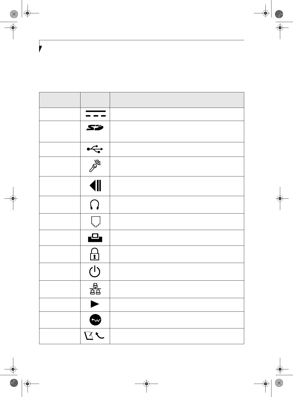
Table 2-1. System icons
Connection LifeBook
Icon Purpose
DC in connector Connect an external power source such as the AC adapter or auto/airline
adapter.
Secure Digital
(SD) Slot The Secure Digital (SD) card slot allows you to install a flash memory card for
data storage. Flash memory cards allow you to transfer data to and from a
variety of different digital devices.
USB Ports Connect Universal Serial Bus 2.0 or 1.1 compliant devices to the notebook.
Microphone Jack Connect an external microphone. The internal microphone is disabled when
you plug in an external microphone.
Fingerprint Sensor Use the fingerprint sensor to log onto the system using your fingerprint as the
"password".
Headphone Jack Connect stereo headphones or powered external speakers. The internal
speaker is disabled when you plug in external headphones or powered
speakers.
Modem Connect a telephone line to the internal modem using a standard RJ-11
telephone plug.
Port Replicator Connect the notebook port replicator or other approved docking device. Refer
to documentation accompanying the dock for more information.
Security lock slot The security slot allows you to secure the notebook using notebook locking
devices.
Suspend/Resume
button
The Suspend/Resume button allows you to suspend notebook activity without
powering off, resume from suspend mode, and power on the system when it
has been shut down from Windows.
Local Area
Network (LAN)
The LAN (RJ-45) jack is used to connect the internal 10/100 Base-T/Tx Ethernet
to a Local Area Network (LAN) in your office or home, or broadband devices
such as a cable modem, DSL, or satellite Internet.
Battery Release
Latch
The battery release latch allows you to remove the battery from your system
for storage or replacement.
Wireless LAN
On-Off Switch
The wireless LAN switch allows you to turn power to the optional wireless LAN
device on and off.
Display Rotation This icon indicates the direction in which the display should be rotated when
converting to tablet mode.
P Series.book Page 8 Wednesday, July 13, 2005 10:43 AM
9
Getting to Know Your Tablet PC
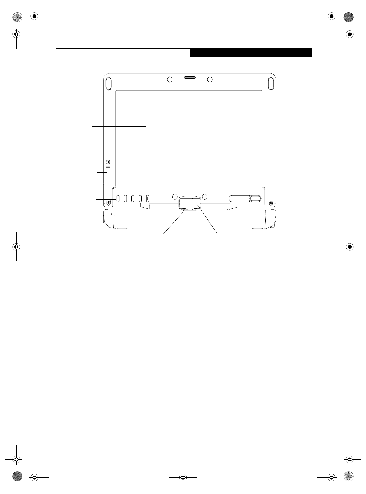
Figure 2-4. LifeBook P Series notebook with display open
FRONT AND DISPLAY COMPONENTS
The following is a brief description of the front and
display features of the LifeBook P Series notebook.
(Figure 2-4)
Display Panel Latch
The display panel latch holds the display panel in posi-
tion.
Display Panel
The display panel is a color LCD panel with back
lighting for the display of text and graphics and touch
screen functionality.
Built-in Microphone
The built-in microphone allows you to input mono
audio.
LifeBook Application Buttons
The LifeBook P Series notebook Application Buttons
provide application launch capabilities. See “LifeBook
Application Panel” on page 20.
Suspend/Resume Button
The Suspend/Resume button allows you to suspend
notebook activity without powering off, resume your
notebook from standby mode, and power on your
system when it has been shut down from the Windows
operating system. See “Power On” on page 30.
Keyboard
A full-function keyboard with dedicated Windows keys.
See “Keyboard” on page 18.
Touchpad Pointing Device
The Touchpad pointing device consists of two mouse-
like buttons and one scroll button. See “Quick Point
Pointing Device/Touch Screen” on page 22.
Rotation Hinge
The rotation hinge allows you to transform your
computer from a notebook configuration into a tablet
configuration. See “Using the System as a Tablet” on
page 16.
Fingerprint Sensor
The optional fingerprint recognition sensor allows you
to start your system by swiping your finger over the
sensor. See “Fingerprint Sensor Device” on page 101.
Status Indicator Panel
The Status Indicator Panel displays symbols that corre-
spond to specific components of your LifeBook P Series
notebook. See “Status Indicators” on page 14.
Display
Status
LifeBook
Indicator
Panel
Panel
Latch
Rotation Hinge
Application
Suspend/
Resume
Button
Built-in Microphone
Fingerprint
Sensor
Buttons
Touchpad Pointing
Device (in front of keyboard)
P Series.book Page 9 Wednesday, July 13, 2005 10:43 AM
10
LifeBook P Series Notebook - Section Two
Figure 2-5. LifeBook P Series notebook left-side panel
LEFT-SIDE PANEL COMPONENTS
Following is a brief description of your notebook’s left-
side components. (Figure 2-5)
USB 2.0 Port
The USB 2.0 port allow you to connect Universal Serial
Bus devices. See “Universal Serial Bus Ports” on page 46.
Compact Flash Card Slot
The Compact Flash (CF) Card Slot allows you to insert a
CF Card. The CF Card Eject Button is used when
ejecting a CF Card from the slot. See “Inserting Compact
Flash Cards” on page 42.
Microphone Jack
The microphone jack allows you to connect an external
mono microphone. See “Microphone Jack” on page 46.
Headphone Jack
The headphone jack allows you to connect stereo head-
phones or powered external speakers. See “Headphone
Jack” on page 46.
Compact Flash Card Slot
USB 2.0 Port Compact Flash Card
Eject Button
Headphone Jack
Microphone Jack
P Series.book Page 10 Wednesday, July 13, 2005 10:43 AM

11
Getting to Know Your Tablet PC
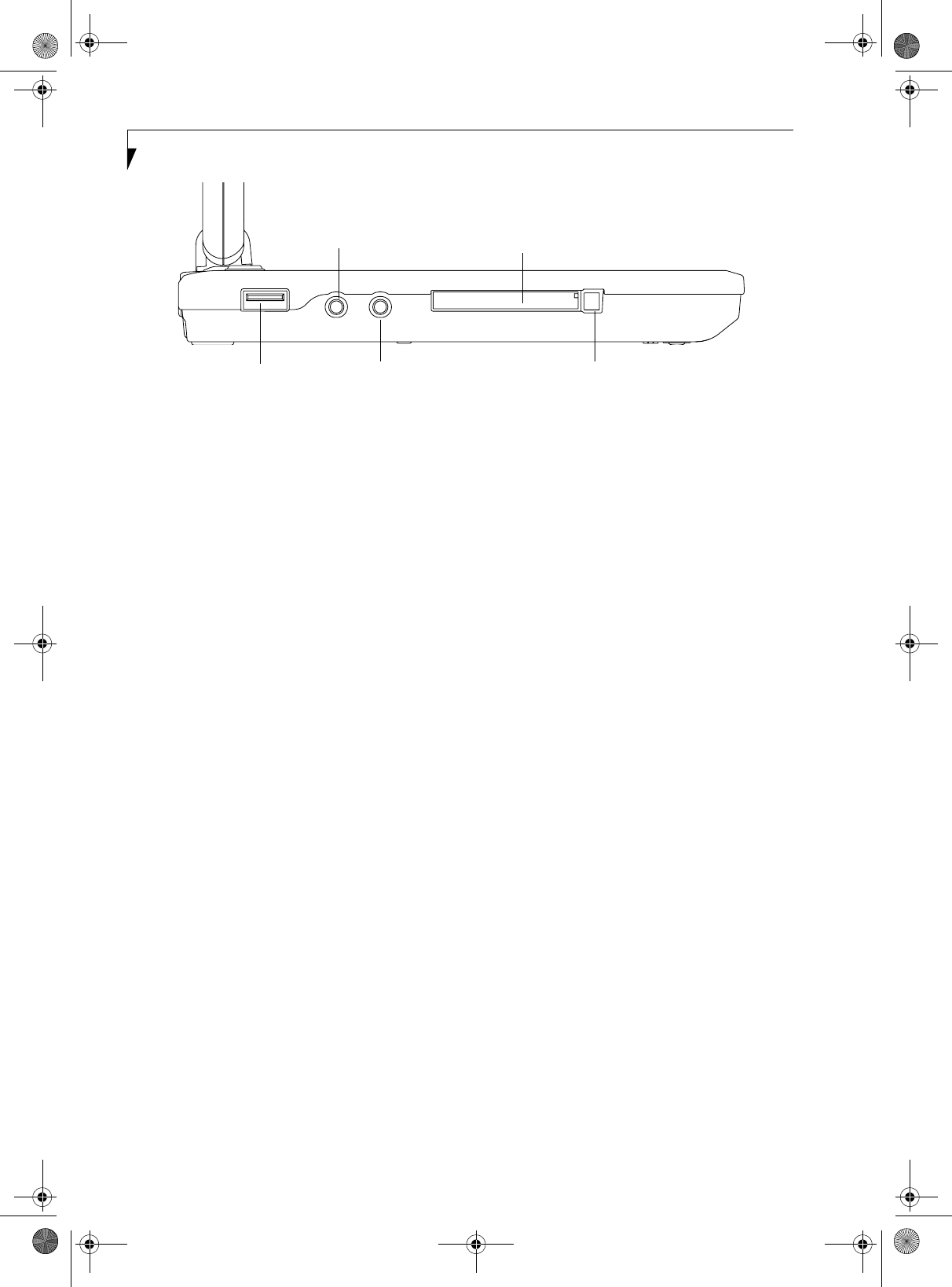
Figure 2-6. LifeBook P Series notebook right-side panel
RIGHT-SIDE PANEL COMPONENTS
Following is a brief description of your notebook’s right-
side components.
Pen/Pen Holder
The pen is used as the interface with the digitizer display.
WLAN On/Off Switch
The wireless LAN On/Off Switch is used to power off the
wireless antenna when not in use.
SD Card
The Secure Digital (SD) card slot allows you to insert a
flash memory card for data storage. Flash memory cards
allow you to transfer data to and from a variety of
different digital devices.
USB 2.0 Port
The USB 2.0 port allow you to connect Universal Serial
Bus devices. See “Universal Serial Bus Ports” on page 46.
DC Power Jack
The DC power jack allows you to plug in the AC adapter
or the optional Auto/Airline adapter to power your
notebook and charge the internal Lithium ion Battery.
USB 2.0 Port
Secure Digital (SD) Card Slot
Pen/Pen Holder
WLAN On/Off Switch DC Power Jack
P Series.book Page 11 Wednesday, July 13, 2005 10:43 AM
12
LifeBook P Series Notebook - Section Two
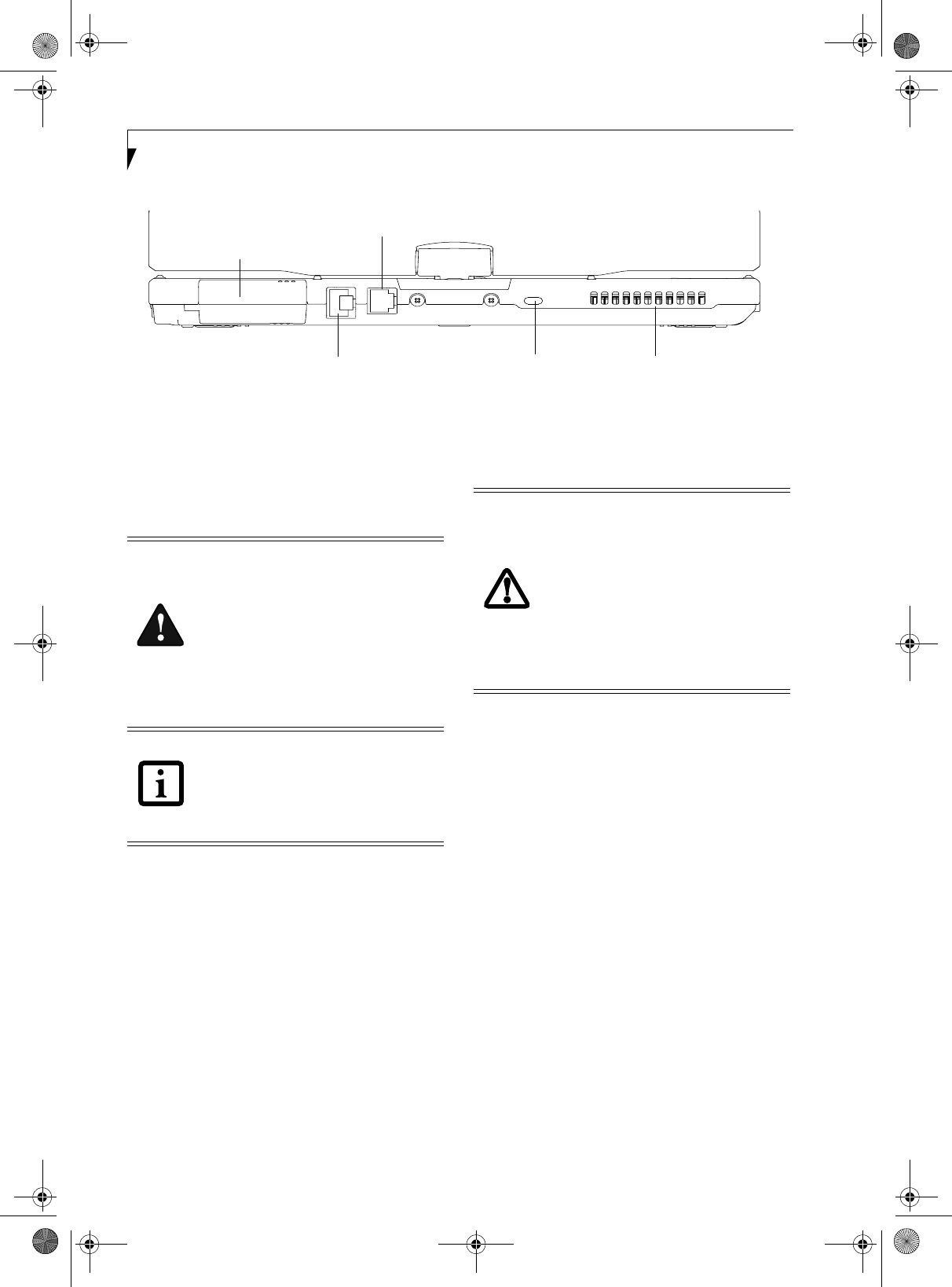
Figure 2-7. LifeBook P Series notebook rear panel
REAR PANEL COMPONENTS
Modem (RJ-11) Telephone Port
The Modem (RJ-11) telephone port is for attaching
a telephone line to the internal multinational 56K
modem.
Anti-theft Lock Slot
The anti-theft lock slot allows you to attach a optional
physical lock-down device.
LAN (RJ-45) Port
The internal LAN (RJ-45) port is used for an internal 10/
100Base-Tx Ethernet. See “Internal LAN (RJ-45) jack”
on page 46.
External Video Port
The external video port allows you to connect an
external CRT monitor or LCD projector. Note that when
the optional Port Replicator is attached to the system,
you must use the external video port on the Port Repli-
cator rather than the port on the system. See “External
Video Port” on page 47.
Air Vents
The air vents allow proper air circulation to ensure that
the notebook does not overheat.
External
LAN (RJ-45) Port
Modem (RJ-11) Port
Video Port
Air VentsAnti-theft Lock Slot
(behind cover)
The internal multinational modem is not
intended for use with Digital PBX systems.
Do not connect the internal modem to a
Digital PBX as it may cause serious damage
to the internal modem or your entire
LifeBook P Series notebook. Consult your
PBX manufacturer’s documentation for
details. Some hotels have Digital PBX
systems. Be sure to find out BEFORE you
connect your modem.
The internal modem is designed to the
ITU-T V.90 standard. Its maximum speed
of 53000 bps is the highest allowed by
FCC, and its actual connection rate
depends on the line conditions. The
maximum speed is 33600 bps at upload.
To protect your notebook from damage
and to optimize system performance, be
sure to keep all air all vents unobstructed,
clean, and clear of debris. This may
require periodic cleaning, depending upon
the environment in which the system is
used.
Do not operate the notebook in areas
where the air vents can be obstructed,
such as in tight enclosures or on soft
surfaces like a bed or cushion.
P Series.book Page 12 Wednesday, July 13, 2005 10:43 AM
13
Getting to Know Your Tablet PC
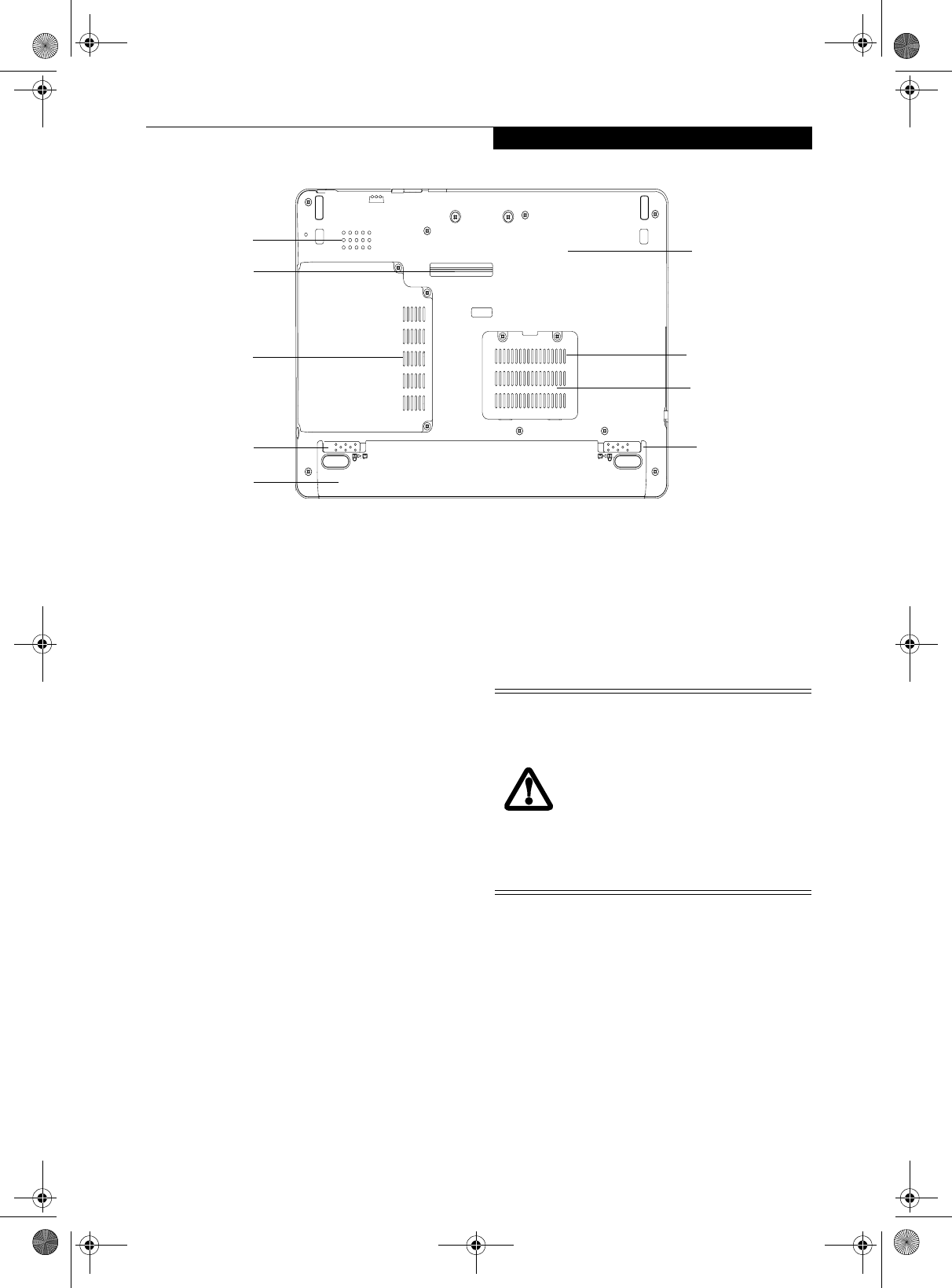
Figure 2-8. LifeBook P Series notebook bottom panel
BOTTOM COMPONENTS
Following is a brief description of your notebook’s
bottom panel components. (Figure 2-8)
Lithium ion Battery Compartment
The battery compartment contains the internal Lithium
ion battery. The battery should be removed when the
computer is stored over a long period of time or for
swapping a discharged battery with a charged Lithium
ion battery. See “Lithium ion Battery” on page 37.
Port Replicator Connector
This connector allows you to connect the optional port
replicator.
Speaker
The speaker allows you to listen to sound from your
system.
Main Unit and Configuration Label
The configuration label shows the model number and
other information about your LifeBook P Series note-
book. In addition, the configuration portion of the label
has the serial number and manufacturer information
that you will need to give your support representative. It
identifies the exact version of various components of
your notebook.
Memory Upgrade Compartment
Your notebook comes with high speed DDR2 Synchro-
nous Dynamic RAM (SDRAM). The memory upgrade
compartment allows you to expand the system memory
capacity of your notebook, hence improving overall
performance. See “Memory Upgrade Module” on
page 39.
Air Vents
The air vents allow proper air circulation to ensure that
the notebook does not overheat.
Memory
Lithium ion
Battery
Main Unit and
Configuration
Label (approximate
Battery
Port Replicator
Connector
location)
Pack
Latch
Battery
Pack
Latch
Upgrade
Compartment
Speaker
Air Vents
Air Vents
To protect your notebook from damage
and to optimize system performance, be
sure to keep all air all vents unobstructed,
clean, and clear of debris. This may
require periodic cleaning, depending upon
the environment in which the system is
used.
Do not operate the notebook in areas
where the air vents can be obstructed,
such as in tight enclosures or on soft
surfaces like a bed or cushion.
P Series.book Page 13 Wednesday, July 13, 2005 10:43 AM
14
LifeBook P Series Notebook - Section Two
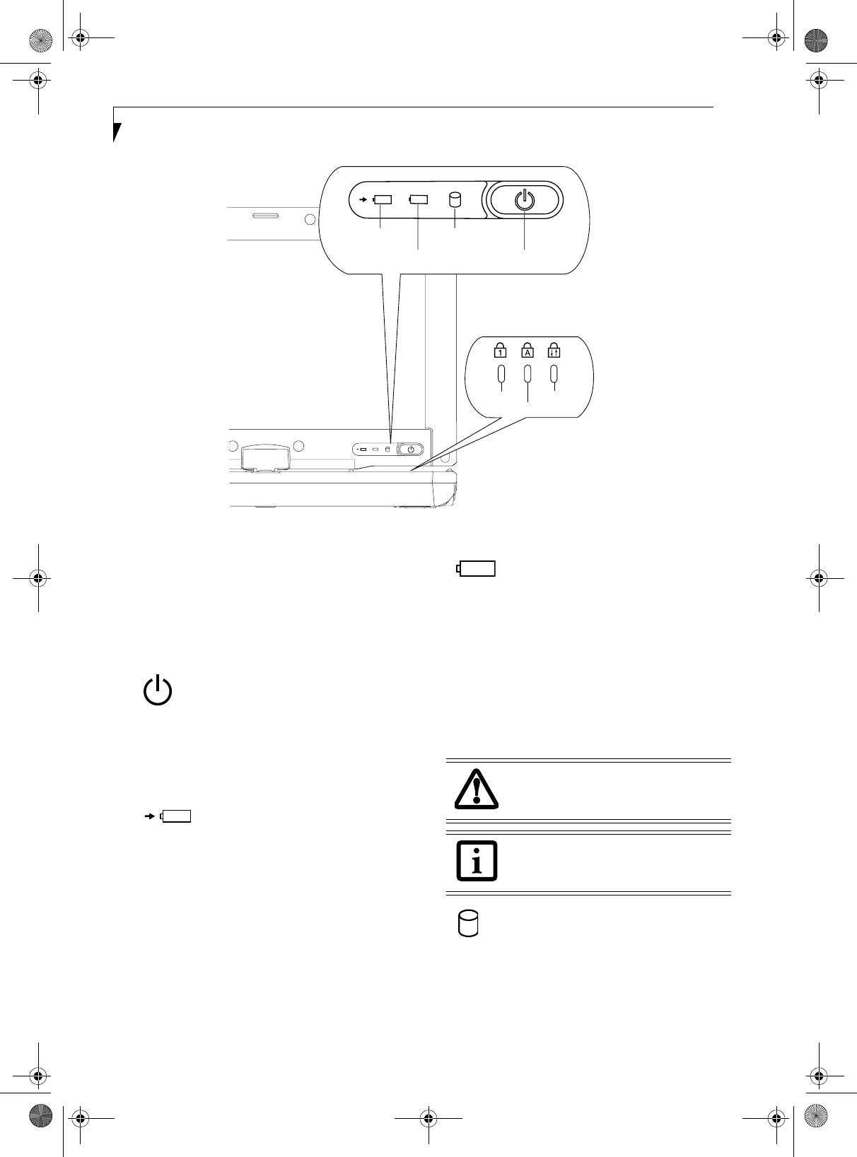
Figure 2-9. Status Indicators
Status Indicators
The status indicators display symbols that correspond to
specific components of your notebook. (Figure 2-9) The
symbols show how each of those components is oper-
ating. Note that keyboard-related indicators (CapsLk,
NumLk, ScrLk) are located above the keyboard.
POWER INDICATOR
The Power indicator symbol located on the power
button shows whether your system is operational. When
it is lit blue, it means that there is power to your note-
book and that it is ready for use.
AC ADAPTER/BATTERY
CHARGING INDICATOR
The AC Adapter/Battery Charging indicator shows that
your notebook is operating from the AC adapter or an
auto/airline adapter. This icon has two different states
that can tell you the battery charge status.
■Green: This means that a power adapter is currently in
use and the battery is not charging.
■Amber: This means that a power adapter is currently
in use and the battery is charging.
BATTERY LEVEL INDICATOR
The Battery Level indicators shows whether the Lithium
ion battery is installed and charging, and how much
charge is available within the batteries.
■Green: The battery is installed and fully charged.
■Amber: The battery is installed and is approximately
half charged.
■Red: The battery charge is low and it should be
charged with an adapter or replaced with a charged
battery.
HARD DRIVE ACCESS INDICATOR
The Hard Drive Access indicator lights green when your
internal hard drive is being accessed.
Battery Level
Hard Drive Access
NumLk
ScrLk
CapsLk
Power Button/
AC Adapter/
Indicator
Charging
Batteries subjected to shocks, vibration or
extreme temperatures can be permanently
damaged.
If there is no battery activity and the
power adapters are not connected, the
Battery Level indicators will also be off.
P Series.book Page 14 Wednesday, July 13, 2005 10:43 AM

15
Getting to Know Your Tablet PC
NUMLK INDICATOR
The NumLk indicator shows that the integral keyboard
is set in ten-key numeric keypad mode.
CAPSLOCK INDICATOR
The CapsLock indicator shows that your keyboard is set
to type in all capital letters.
SCRLK INDICATOR
The ScrLk indicator shows that your scroll lock is active.
P Series.book Page 15 Wednesday, July 13, 2005 10:43 AM
16
LifeBook P Series Notebook - Section Two
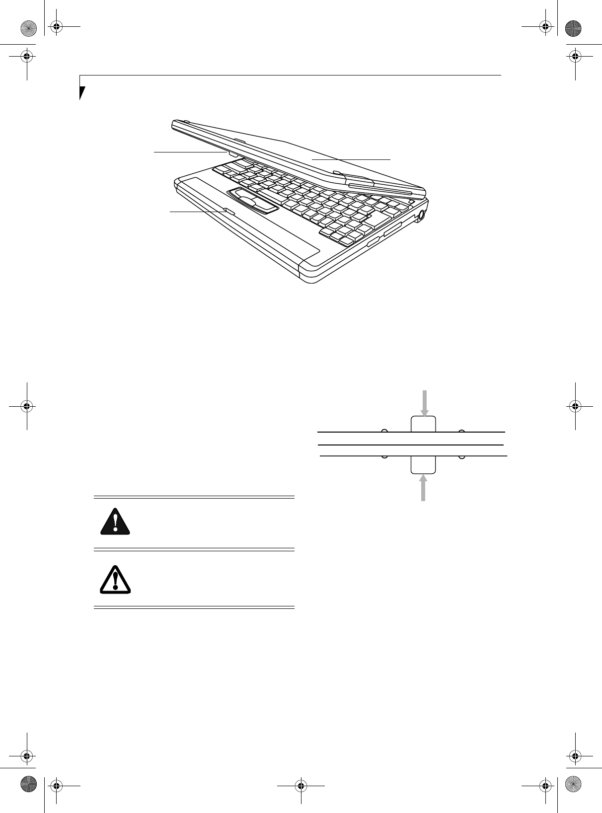
Figure 2-10. Opening the display
Display Panel
The convertible design of your LifeBook P Series note-
book allows you to open the display fully, rotate it 180
degrees, and lay it face up on the keyboard. This allows
you to use the system as a tablet, much as you would a
pad of paper.
OPENING THE DISPLAY PANEL
Lift the display cover backwards, being careful not to
touch the screen, until it is at a comfortable viewing
angle. (Figure 2-10)
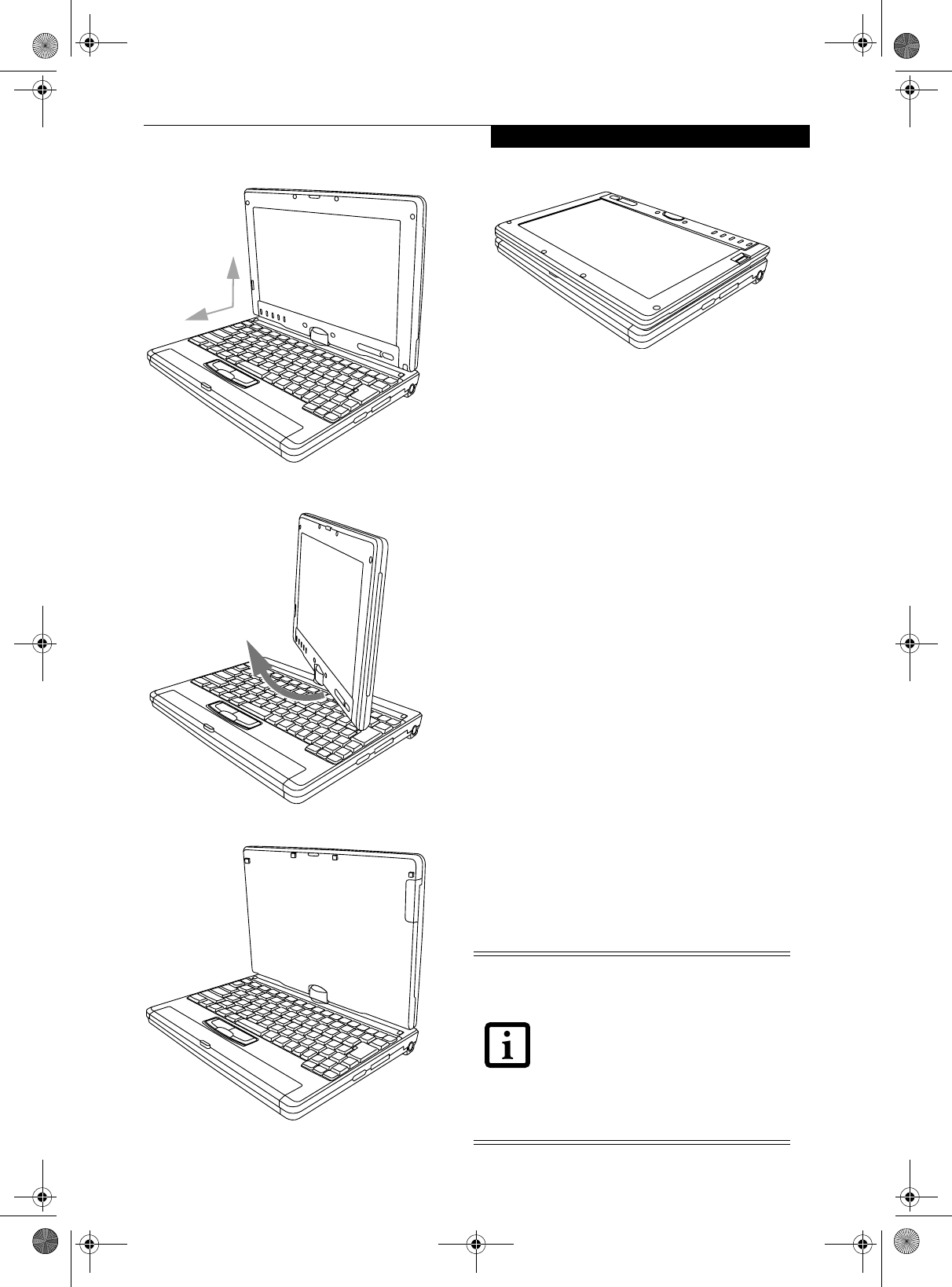
USING THE SYSTEM AS A TABLET
If you would like to use the system as a tablet, perform
the following steps.
1. Lift the display until it is perpendicular to the
keyboard. (Figure 2-12).
2. When the display is perpendicular to the keyboard,
rotate it clockwise (when viewed from the top). Be
very careful to rotate it in the direction indicated.
(Figure 2-13). Turn the display 180 degrees so that it
is facing backwards. (Figure 2-14)
3. Holding the top edge of the display panel, pull it
forward until it is lying nearly atop the keyboard.
4. Push the latch towards the display (See “A” in
Figure 2-11). The latch will click twice and the top
latch disappears, and the bottom latch appears (See
“B” in Figure 2-11). Lay the display flush against the
system so that the latch rests in the slot in the battery
pack. You can now use the system as a tablet.
(Figure 2-15)
Figure 2-11. Using the Display Latch
5. To return the system to notebook configuration,
repeat step 3 and 2. Be sure to turn the display in the
opposite direction when performing step 2.
Display Cover
Latch Slot
Latch
Rotate the system display only in the
direction indicated in the procedure.
Turning the display in the incorrect
direction could damage the hinge.
In the following step, be sure to position
the display perpendicular to the keyboard,
otherwise the keyboard or display cover
could get scratched.
A
B
Top latch
Bottom latch
Display Side
P Series.book Page 16 Wednesday, July 13, 2005 10:43 AM
17
Getting to Know Your Tablet PC
Figure 2-12. Fully open display
Figure 2-13. Rotating the display
Figure 2-14. Display rotated completely
Figure 2-15. System in tablet configuration
ADJUSTING DISPLAY PANEL BRIGHTNESS
Once you have turned on your notebook, you may want
to adjust the brightness level of the screen to a more
comfortable viewing level. There are three ways to adjust
the brightness, keyboard, power management utility,
and Fujitsu menu.
Using Keyboard to Adjust Brightness
Adjusting the brightness using the keyboard changes the
system setting (i.e., the settings you make via the func-
tion keys automatically changes the brightness settings
in the system’s Brightness Control settings).
■[Fn+F6]: Pressing repeatedly will lower the brightness
of your display.
■[Fn+F7]: Pressing repeatedly will increase the
brightness of the display.
Using Power Management to Adjust Brightness
To adjust brightness with the power management utility,
click Start -> Control Panel -> Brightness Control. Set
the screen brightness slider for battery and AC power
scenarios.
Using the Fujitsu Menu to Adjust Brightness
To adjust brightness using the Fujitsu menu, click on the
Fujitsu Menu icon in the system tray in the lower right
corner of the screen. From the menu that appears, select
Brightness Control. The Brightness Control window will
open. Set the screen brightness slider for battery and AC
power scenarios.
90
o
If using AC power, your brightness setting
is set to its highest level by default. If using
battery power your brightness settings is
set to approximately mid-level by default.
The higher the brightness level, the more
power the LifeBook P Series notebook will
consume and the faster your batteries will
discharge. For maximum battery life, make
sure that the brightness is set as low as
possible.
P Series.book Page 17 Wednesday, July 13, 2005 10:43 AM
18
LifeBook P Series Notebook - Section Two
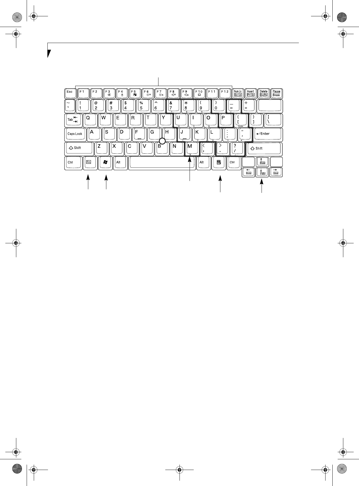
Figure 2-16. Keyboard
Keyboard
USING THE KEYBOARD
Your LifeBook P Series notebook has an integral 82-key
keyboard. The keys perform all the standard functions of
a 101-key keyboard, including the Windows keys and
other special function keys. This section describes the
following keys. (Figure 2-16)
■Numeric keypad: Your notebook allows certain keys to
serve dual purposes, both as standard characters and
as numeric and mathematical keys. The ability to tog-
gle between the standard character and numerical keys
is controlled through the [NumLk] key.
■Cursor keys: Your keyboard contains four arrow
keys for moving the cursor or insertion point to the
right, left, up, or down within windows, applications
and documents.
■Function keys: The keys labeled [F1] through [F12],
are used in conjunction with the [Fn] key to produce
special actions that vary depending on what program
is running.
■Windows keys: These keys work with your Windows
operating system and function the same as the
onscreen Start menu button, or the right button on
your pointing device.
NUMERIC KEYPAD
Certain keys on the keyboard perform dual functions as
both standard character keys and numeric keypad keys.
NumLk can be activated by pressing the [NumLk] key.
Turning off the NumLk feature is done the same way.
Once this feature is activated you can enter numerals 0
through 9, perform addition ( + ), subtraction ( - ),
multiplication ( * ), or division ( / ), and enter decimal
points ( . ) using the keys designated as ten-key function
keys. The keys in the numeric keypad are marked on the
front edge of the key to indicate their secondary func-
tions. (Figure 2-16)
WINDOWS KEYS
Your LifeBook P Series notebook has two Windows keys:
a Start key and an Application key. The Start key displays
the Start menu. This button functions the same as your
onscreen Start menu button. The Application key func-
tions the same as your right mouse button and displays
shortcut menus for the selected item. (Please refer to
your Windows documentation for additional informa-
tion regarding the Windows keys.) (Figure 2-16)
CURSOR KEYS
The cursor keys are the four arrow keys on the keyboard
which allow you to move the cursor up, down, left, and
right in applications. In programs such as Windows
Explorer, it moves the “focus” (selects the next item up,
down, left, or right). (Figure 2-16)
Back
Space
Fn Key Start Key
Function Keys
Numeric Keypad
Application Key Cursor Keys
(outlined with thick
black line)
P Series.book Page 18 Wednesday, July 13, 2005 10:43 AM

19
Getting to Know Your Tablet PC
FUNCTION KEYS
Your notebook has 12 function keys, F1 through F12.
The functions assigned to these keys differ for each
application. You should refer to your software docu-
mentation to find out how these keys are used.
(Figure 2-16)
[Fn] Key
The [Fn] key provides extended functions for the
notebook and is always used in conjunction with
another key.
■[Fn+F3]: Pressing [F3] while holding [Fn] will toggle
the Audio Mute on and off.
■[Fn+F4]: Pressing [F4] while holding [Fn] will toggle
the built-in pointing device on and off. Note that the
[Fn+F4] combination only works if Manual Setting is
selected in the BIOS. (See “Entering the BIOS Setup
Utility” on page 30)
■[Fn +F5]: Pressing [F5] while holding [Fn] allows
you to toggle between video compensation and no
compensation. (Video compensation controls spacing
on the display. When it is enabled, displays with less
than 1024 x 768 or 800 x 600 pixel resolution will still
cover the entire screen.)
■[Fn+F6]: Pressing [F6] repeatedly while holding [Fn]
will lower the brightness of your display. Note that
adjusting the brightness using the keyboard changes
the system setting.
■[Fn+F7]: Pressing [F7] repeatedly while holding [Fn]
will increase the brightness of the display.
■[Fn+F8]: Pressing [F8] repeatedly while holding [Fn]
will decrease the volume of your notebook.
■[Fn+F9]: Pressing [F9] repeatedly while holding [Fn]
will increase the volume of your notebook.
■[Fn+F10]: Pressing [F10] while holding [Fn] allows
you to change your selection of where to send your
display video. Each time you press the combination
of keys you will step to the next choice. The choices,
in order, are: built-in display panel only, both built-in
display panel, and external monitor or external moni-
tor only.
P Series.book Page 19 Wednesday, July 13, 2005 10:43 AM
20
LifeBook P Series Notebook - Section Two
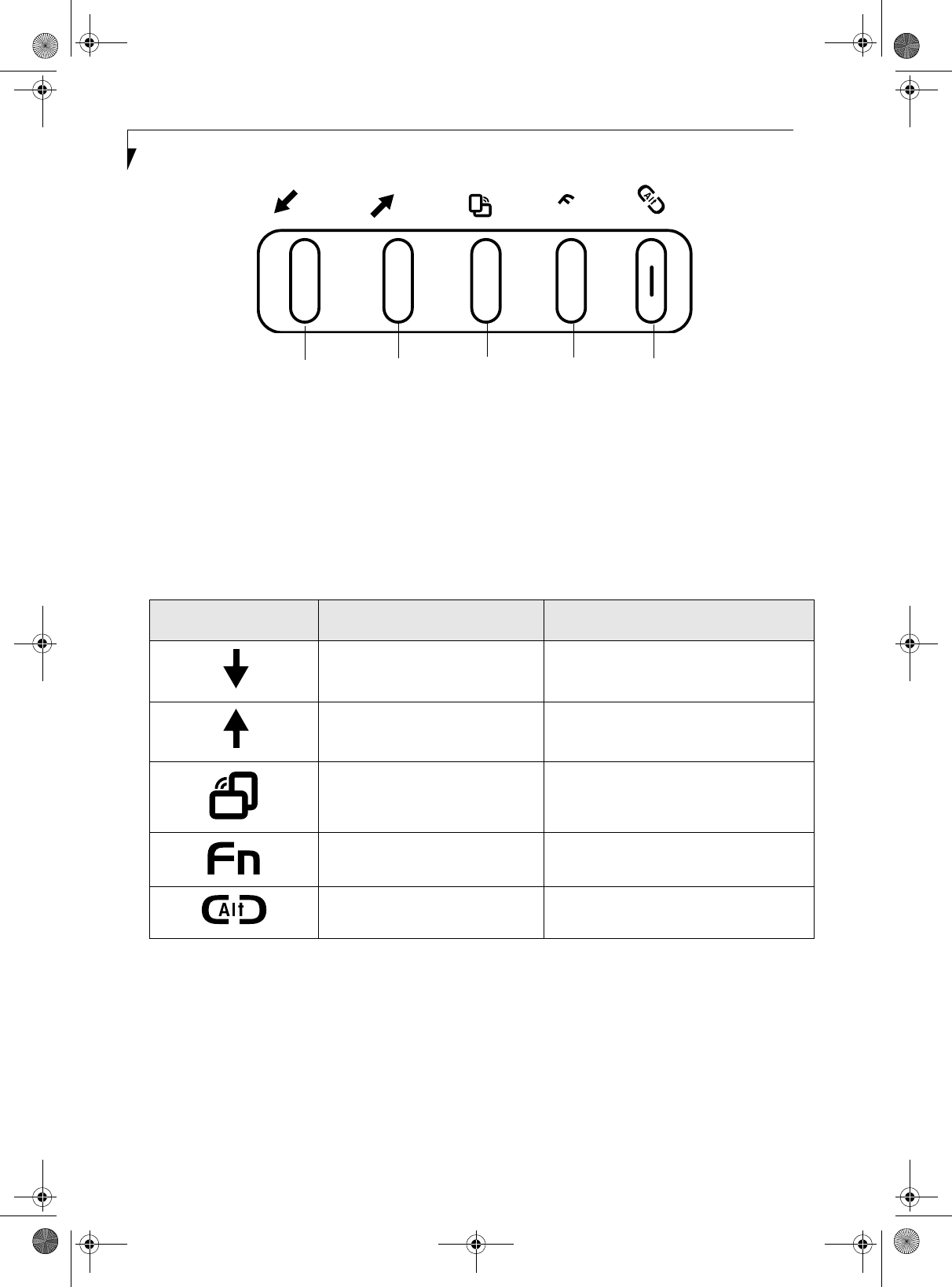
Figure 2-17. LifeBook P Series notebook application buttons
LifeBook Application Panel
A unique feature of your LifeBook P Series notebook is
the application panel buttons. These buttons allow you
to launch specific applications with the touch of a
button.
The five application buttons are located on the bottom
left-hand side of the display when it is configured to be
used as a notebook. (Figure 2-17)
All five of the buttons have primary functions. Four of
the buttons have secondary functions when used as
application buttons. The secondary functions are acti-
vated by pressing the Function (Fn) button while
pressing the application button. See Table 2-2 for
specific functions. The secondary functions of the
Application A and B buttons can be changed to launch
any application. See “Changing Button Functions” on
page 21.
Table 2-2. Application Button Functions
Page Down / Application A Button
When you press the Page Down button when the system
is running, each press of the button will scroll the screen
down one frame. This allows you to navigate quickly
through large documents.
When you press the Fn button while you press then
release the Page Down/Application A button, you will
automatically start whichever program is assigned to the
button. The default application for this button is Calcu-
lator.
See “Changing Button Functions” on page 21 to select a
different application for this button.
Page Up / Application B Button
When you press the Page Up button when the system is
running, each press of the button will scroll the screen
up one frame. This allows you to navigate quickly
through large documents.
When you press the Fn button while you press then
release the Page Up/Application A button, you will
..
A
B
n
Application A Application B
Button 4
Enter
Button Button
Button 3
Button
Button Icon Primary Function Secondary Function
(Fn + Button)
Page Down User-defined Application A
(Default = Calculator
Page Up User-Defined Application B
(Default = WordPad
Screen Rotation VGA-Out
Secondary Function Selection Fujitsu Menu Utility
Ctl+Alt+Del Button None
P Series.book Page 20 Wednesday, July 13, 2005 10:43 AM

21
Getting to Know Your Tablet PC
automatically start whichever program is assigned to the
button. The default application for this button is
Word Pad .
See “Changing Button Functions” on page 21. to select a
different application for this button.
Screen Rotation / VGA-Out Button
The screen rotation feature would normally be used
only when the system is configured as a tablet. When
you would like to use the tablet as an eBook, for
example, you would use the portrait orientation; when
accessing spreadsheets or using the system as a note-
book, you would more typically use landscape orienta-
tion.
When the system is changed to tablet configuration, the
orientation automatically changes to portrait mode by
default.
When you press the Screen Rotation / VGA-Out button,
the system screen orientation changes from portrait
(vertical) to landscape (horizontal) or from landscape to
portrait.
Function / Fujitsu Menu Utility Button
The Function button works in conjunction with the
other application buttons to provide additional func-
tionality for the buttons. Refer to specific details above.
Pressing the Fn button twice in succession causes the
Fujitsu Menu Utility to appear on your screen, allowing
you to modify certain system settings.
Ctl+Alt+Del Button
Pressing and holding the Ctl-Alt-Del button for up to
750 milliseconds launches the Logon screen or the
Windows Task Manager (if the system hasn’t yet been
configured).
CHANGING BUTTON FUNCTIONS
The Application A and B buttons can be changed to
launch a program or perform an action you select. By
default, the Application A button launches the Calcu-
lator, and the Application B button launches WordPad.
To launch different applications or cause the Applica-
tion A or B buttons to perform a specific action:
1. Double-click on the Tablet Button Settings icon in
the Control Panel.
2. Select the button you would like to change from the
list.
3. Click [Change] and open the drop down list in the
Action: field.
4. Select the action you would like the button to
perform. If you want to launch a program, click on
Launch an Application then browse to the location
of the program.
5. Click [OK], then click [OK] again. The buttons will
now perform the actions you have assigned to them.
The screen orientation default can be
changed by going to the Control Panel and
double-clicking on the Fujitsu Display
Control icon and selecting the desired
defaults from the Display Orientation
section. After changing the defaults, click
[OK].
P Series.book Page 21 Wednesday, July 13, 2005 10:43 AM
22
LifeBook P Series Notebook - Section Two
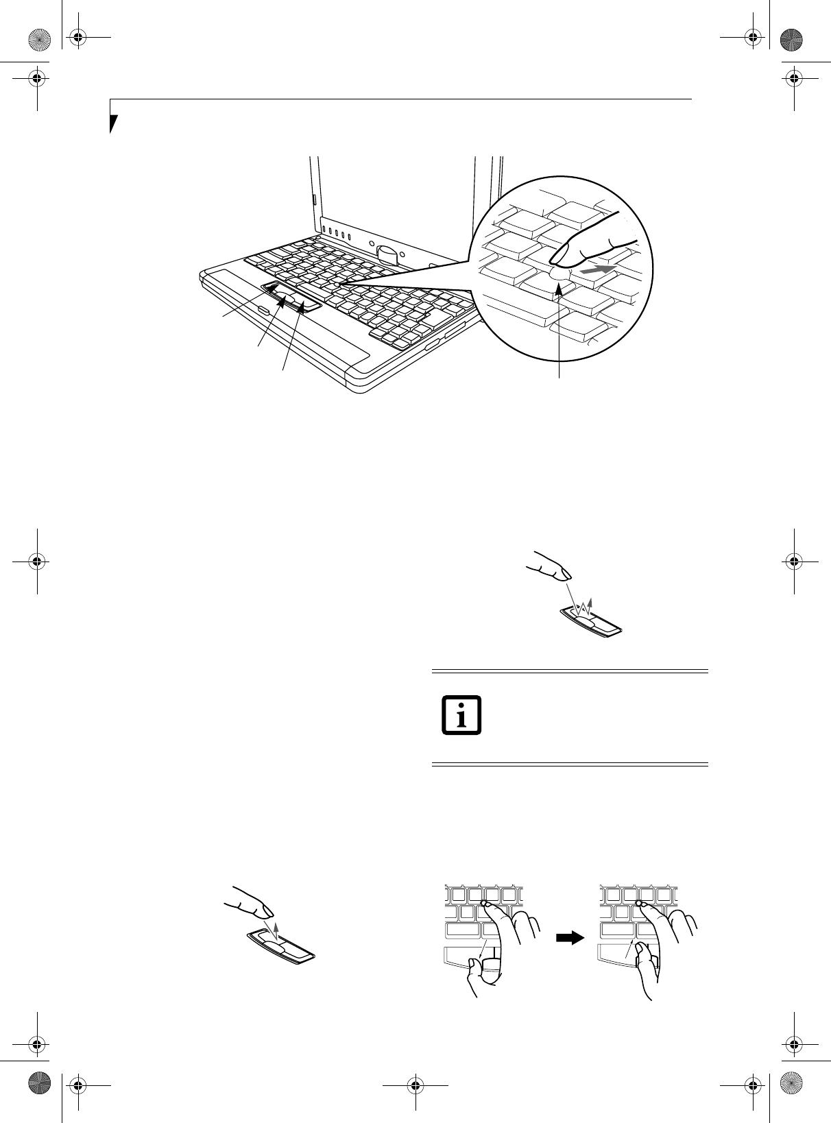
Figure 2-18. Touchpad pointing device
Quick Point Pointing
Device/Touch Screen
The Quick Point is built into your LifeBook notebook. It
is used to control the movement of the cursor to select
items on your display panel. The Quick Point is
composed of a cursor control at the center of the
keyboard and three buttons on the palm rest of your
notebook. The cursor control works the same way a
mouse ball does, and moves the cursor around the
display. It only requires light pressure with the tip of
your finger, and the more pressure you use, the faster the
cursor will move. The left button functions the same as a
left mouse button while the right button has the same
function as a right mouse button. When used with the
cursor control, the middle button allows you to scroll up
and down a screen. The actual functionality of the
buttons may vary depending on the application that is
being used. (Figure 2-19)
CLICKING
Clicking means pushing and releasing a button. To left-
click, move the cursor to the item you wish to select,
press the left button once, and then immediately release
it. To right-click, move the cursor to the item you wish
to select, press the bottom button once, and then imme-
diately release it. (Figure 2-19)
Figure 2-19 Clicking
DOUBLE-CLICKING
Double-clicking means pushing and releasing the left
button twice in rapid succession. This procedure does
not function with the right button. To double-click,
move the cursor to the item you wish to select, press and
release the left button twice. (Figure 2-20)
Figure 2-20 Double-clicking
DRAGGING
Dragging means pressing and holding the left button,
while moving the cursor. To drag, move the cursor to the
item you wish to move. Press and hold the left button
while moving the item to its new location and then
release it. (Figure 2-21)
Figure 2-21 Dragging
Left Button
Right Button
Scroll Button
Cursor Control
■If the interval between clicks is too long,
the double-click will not be executed.
■Parameters for the Quick Point can be
adjusted from the Mouse dialog box
located in the Windows Control Panel.
P Series.book Page 22 Wednesday, July 13, 2005 10:43 AM
23
Getting to Know Your Tablet PC
QUICK POINT CONTROL ADJUSTMENT
The Windows Control Panel allows you to customize
your Quick Point with selections made from within the
Mouse Properties dialog box. There are three aspects of
Quick Point operation, which you can adjust:
■Buttons: This tab lets you set up the buttons for right
or left handed operation, in addition to setting up the
time interval allowed between clicks in double-click-
ing.
■Pointers: This tab lets you set up the scheme for
the cursor depending on its functionality.
■Pointer Options: This tab lets you set up a relation
between the speed of your finger motion and the speed
of the cursor. It also allows you to enable a Pointer
Trail for the cursor arrow.
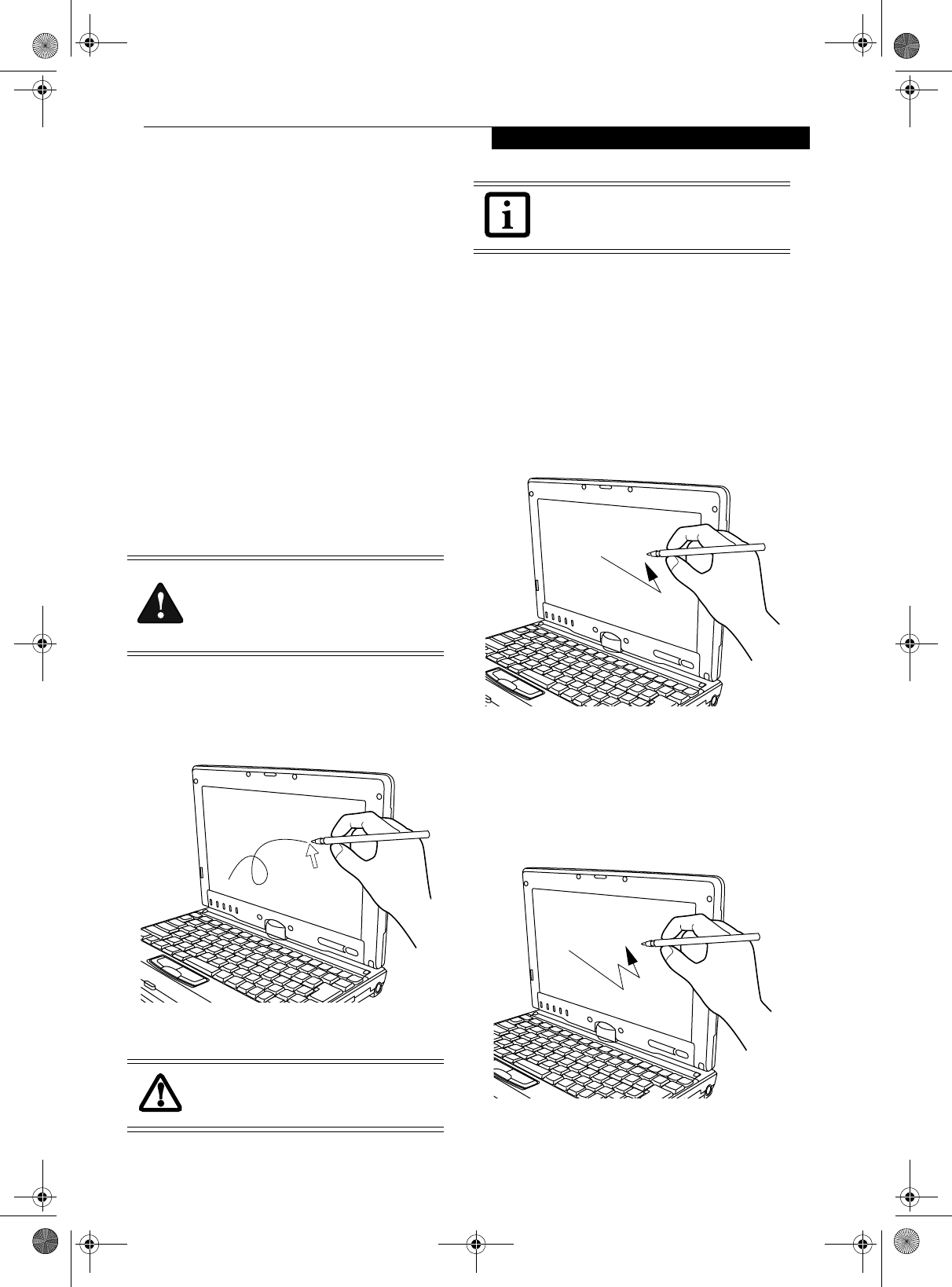
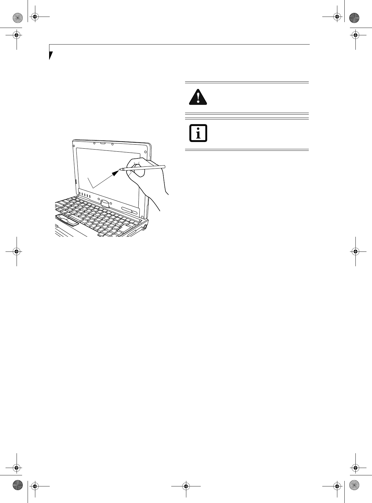
TOUCH SCREEN
The integrated Touch Screen allows you to use either the
included stylus or your fingertip, as a pointing device.
You can use the stylus to click, double-click, drag items
and icons, or to draw like a pen or pencil in applications
that support this behavior, such as drawing or painting
programs. See the documentation that came with your
application for details. (Figure 2-22)
Figure 2-22 Using the Stylus with the Touch Screen
Clicking
To left-click, touch the object you wish to select and then
lift the stylus tip immediately. You also have the option
to perform the left-click operation by tapping lightly
with your finger on the Touch Screen once. (Figure 2-23)
Right-Clicking
To right-click, go to Start -> Control Panel -> Touch
Panel. From the Right Button Simulation tab you can
specify a right button tool by using the selected button
prior to the desired right mouse click.
Figure 2-23 Clicking the Touch Screen
Double-Clicking
To double-click, touch the item twice, and then immedi-
ately remove the stylus tip. You also have the option to
perform the double-click operation by tapping lightly
with your finger on the Touch Screen twice.
(Figure 2-24)
Figure 2-24 Double-clicking the Touch Screen
Do not use excessive force when tapping
or writing on the screen with the stylus or
your finger. Use of excessive force could
result in damage to the LCD and/or Touch
Screen.
To avoid potential scratching and damage,
never use anything but the included stylus
or your finger with the Touch Screen.
To purchase additional or replacement
styluses, visit Fujitsu’s accessories web site
at: www.shopfujitsu.com.
P Series.book Page 23 Wednesday, July 13, 2005 10:43 AM
24
LifeBook P Series Notebook - Section Two
Dragging
Dragging means moving an item with the stylus by
touching the screen, moving and then lifting the stylus.
To drag, touch the Touch Screen with your stylus on the
item you wish to move. While continuing to touch the
screen with the stylus, drag the item to its new location
by moving the stylus across the screen, and then lifting
the stylus to release it. Dragging can also be done using
your fingertip. (Figure 2-25)
Figure 2-25 Dragging on the Touch Screen
Calibrating the Touch Screen
In order to ensure accurate tracking between the stylus
and cursor, you must run the Touch Screen Calibration
Utility before you use the Touch Screen for the first time,
or after you change the display resolution and/or orien-
tation.
To run the calibration utility:
1. Go to Start -> Control Panel -> Touch Panel and
select the Calibration tab.
2. Press the [Calibrate Now] button.
3. Adjust the display of your notebook to a comfortable
angle and find the red (+) symbol in the upper-left
corner of the display.
4. Using the stylus, firmly touch the screen directly on
the (+) symbol. Lift the stylus from the screen and
the target will move to a different location on the
screen.
5. Repeat step 4 until you have selected a total of nine
symbols. This is the minimum number of points
necessary to calibrate your touch screen.
6. Once you have selected the nine symbols, press the
[Update] button.
7. Touch the stylus to various points on the screen to
verify that the screen is correctly calibrated. If you
are not satisfied with the screen’s calibration, press
the [Calibrate Now] button to begin again.
Do not use excessive force when tapping
on the screen during calibration. Use of
excessive force could result in damage to
the LCD and/or touch panel.
When using the stylus to calibrate the
screen, be sure to avoid touching the
screen with your fingers; doing so could
result in faulty calibration.
P Series.book Page 24 Wednesday, July 13, 2005 10:43 AM
25
Getting to Know Your Tablet PC
Volume Control
Your Fujitsu LifeBook notebook has multiple volume
controls which interact with each other.
CONTROLLING THE VOLUME
The volume can be controlled in several different ways:
■Volume can be set from within the Volume Control on
the Taskbar.
■Volume can be controlled with the [F8] and [F9] func-
tions keys. Pressing [F8] repeatedly while holding [Fn]
will decrease the volume of your notebook. Pressing
[F9] repeatedly while holding [Fn] will increase the
volume of your notebook.
■Volume can be controlled by many volume controls
that are set within individual applications.
■Certain external audio devices you might connect to
your system may have hardware volume controls.
■Each source discussed above puts an upper limit on
the volume level that must then be followed by the
other sources.
We recommend that you experiment with the various
volume controls to discover the optimal sound level.
Any software that contains audio files will
also contain a volume control of its own. If
you install an external audio device that has
an independent volume control, the
hardware volume control and the software
volume control will interact with each other.
It should be noted that if you set your
software volume to Off, you will override
the external volume control setting.
There are twenty-six levels through which
the function keys cycle.
P Series.book Page 25 Wednesday, July 13, 2005 10:43 AM

26
LifeBook P Series Notebook - Section Two
P Series.book Page 26 Wednesday, July 13, 2005 10:43 AM

27
3
Using Your LifeBook
P Series.book Page 27 Wednesday, July 13, 2005 10:43 AM

28
LifeBook P Series Notebook - Section Three
P Series.book Page 28 Wednesday, July 13, 2005 10:43 AM
29
Getting Started
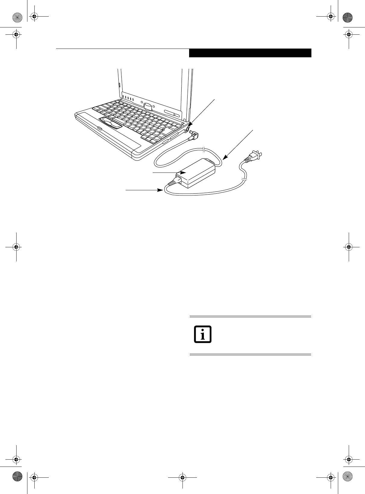
Figure 3-1. Connecting the AC Adapter
Power Sources
Your LifeBook P Series notebook has three possible
power sources: a primary Lithium ion battery, an AC
adapter or an optional Auto/Airline adapter.
CONNECTING THE POWER ADAPTERS
The AC adapter or optional Auto/Airline adapter
provides power for operating your notebook and
charging the battery.
Connecting the AC Adapter
1. Plug the DC output cable into the DC power jack
of your notebook.
2. Plug the AC adapter into an AC electrical outlet.
(Figure 3-1)
Connecting the Optional Auto/Airline Adapter
1. Plug the DC output cable into the DC power jack
on your notebook.
2. Plug the Auto/Airline adapter into the cigarette
lighter of an automobile with the ignition key in
the On or Accessories position.
OR
3. Plug the Auto/Airline adapter into the DC power
jack on an airplane seat.
Switching from AC Adapter Power or the
Auto/Airline Adapter to Battery Power
1. Be sure that you have a charged battery installed.
2. Remove the AC adapter or the Auto/Airline adapter.
DC Power Plug
DC Output Cable
AC Adapter
AC Cable
The Lithium ion battery is not charged
upon purchase. Initially, you will need to
connect either the AC adapter or the
Auto/Airline adapter to use your
notebook.
P Series.book Page 29 Wednesday, July 13, 2005 10:43 AM
30
LifeBook P Series Notebook - Section Three
Starting Your LifeBook
POWER ON
The Suspend/Resume button is used to turn on your
LifeBook P Series notebook from its off state. Once you
have connected your AC adapter or charged the internal
Lithium ion battery, you can power on your notebook.
(See figure 2-4 on page 9 for location).
Press the Suspend/Resume button to start your system.
When you are done working you can either leave your
notebook in Standby mode, See “Standby Mode” on
page 32., or you can turn it off. See “Power Off” on
page 34..
When you Power On your notebook, it will perform a
Power On Self Test (POST) to check the internal parts
and configuration for correct functionality. If a fault is
found, your notebook will emit an audio warning and/
or an error message will be displayed. See “Power On Self
Test Messages” on page 58. Depending on the nature of
the problem, you may be able to continue by starting the
operating system or by entering the BIOS setup utility
and revising the settings.
After satisfactory completion of the Power On Self Test
(POST), your notebook will load your operating system.
BOOT SEQUENCE
The procedure for starting-up your notebook is termed
the Bootup sequence and involves your notebook’s
BIOS. When your notebook is first turned on, the main
system memory is empty, and it needs to find instruc-
tions to start up your notebook. This information is in
the BIOS program. Each time you power up or restart
your notebook, it goes through a boot sequence which
displays a Fujitsu logo until your operating system is
loaded. During booting, your notebook is performing a
standard boot sequence including a Power On Self Test
(POST). When the boot sequence is completed without
a failure and without a request for the BIOS Setup
Utility, the system displays the operating system’s
opening screen.
The boot sequence is executed when:
■You turn on the power to your notebook.
■You restart your notebook from the Windows Shut
Down dialog box.
■The software initiates a system restart (e.g., when you
install a new application).
BIOS SETUP UTILITY
The BIOS Setup Utility is a program that sets up the
operating environment for your notebook. Your BIOS
is set at the factory for normal operating conditions,
therefore there is no need to set or change the BIOS’
environment to operate your notebook.
The BIOS Setup Utility configures:
■Device control feature parameters, such as changing
I/O addresses and boot devices.
■System Data Security feature parameters, such
as passwords.
Entering the BIOS Setup Utility
To enter the BIOS Setup Utility do the following:
1. Turn on or restart your notebook.
2. Press the [F2] key once the Fujitsu logo appears on
the screen. This will open the main menu of the
BIOS Setup Utility with the current settings
displayed.
3. Press the [RIGHT ARROW] or [LEFT ARROW] key
to scroll through the other setup menus to review or
alter the current settings.
BIOS Guide
A guide to your notebook’s BIOS is available online.
Please visit our service and support Web site at http://
www.computers.us.fujitsu.com/support. Once there,
select LifeBook BIOS Guides from the pull-down menu
for your notebook series. If you are unsure of your note-
book’s BIOS number, refer to your packing slip.
When you turn on your notebook, be sure
you have a power source. This means that
a battery is installed and charged, or that a
power adapter is connected and has
power.
When the system display is closed, the
Suspend/Resume button is disabled. This
feature prevents the system from being
accidentally powered up when not in use.
Never turn off your notebook during the
Power On Self Test (POST) or it will cause
an error message to be displayed when
you turn your notebook on the next time.
See “Power On Self Test Messages” on
page 58.
If your data security settings require it, you
may be asked for a password before the
BIOS main menu will appear.
P Series.book Page 30 Wednesday, July 13, 2005 10:43 AM
31
Getting Started
BOOTING THE SYSTEM
We strongly recommend that you not attach any
external devices until you have gone through the initial
power on sequence.
When you turn on your LifeBook notebook for the first
time, it will display a Fujitsu logo on the screen. If you
do nothing the system will load the operating system,
and then the Windows Welcome will begin.
Registering Windows with Microsoft
In order to ensure that you receive the most benefits
from the Windows operating system, it should be
registered the first time you use it.
After you receive the Windows Welcome screen, you will
be prompted to enter registration information in the
following order.
First of all, you will need to read and accept the End
User License Agreements (EULAs). After accepting the
EULAs, you will be asked if you want to enable the Auto-
matic Updates feature. Acceptance of this feature is
recommended because it allows your system to be
updated automatically whenever an important change
becomes available for your notebook.
Several additional windows will appear, prompting you
to enter a name and description for your computer, an
Administrator password, and a domain name. Read the
instructions on the screens carefully and fill in the infor-
mation as directed.
You will then be automatically connected to the
Internet, if you have an appropriate connection avail-
able. If an automatic connection is not possible, you will
be asked about how you dial out from where you will be
using your LifeBook notebook. If you are not connected
to a phone line and plan to register at a later time, you
may click the Skip button.
Once you are connected to the Internet, you will be
asked if you wish to continue with the registration. If
you select Ye s you will then enter your name and
address, and email address if desired. Click Next to
complete registration.
REGISTERING YOUR LIFEBOOK NOTEBOOK
How do I register my LifeBook notebook?
You can register your LifeBook by going to our Web site:
http://www.computers.us.fujitsu.com/support
You will need to be set up with an Internet Service
Provider (ISP) to register online.
INSTALLING CLICK ME!
The first time you boot up your system, you will see an
icon called Click Me! in the Start menu. When you click
the Click Me! icon, your system will automatically build
the icon tray in the bottom right of the screen. These
icons provide links to utilities that you will frequently
access.
■If you reject the terms of the license
agreement you will be asked to review
the license agreement for information
on returning Windows or to shut down
your LifeBook notebook.
■You cannot use your LifeBook notebook
until you have accepted the License
Agreement. If you stop the process your
notebook will return to the beginning of
the Windows Welcome Process, even if
you shut your notebook down and start
it up again.
ClickMe!
P Series.book Page 31 Wednesday, July 13, 2005 10:43 AM

32
LifeBook P Series Notebook - Section Three
Power Management
Your LifeBook P Series notebook has many options and
features for conserving battery power. Some of these
features are automatic and need no user intervention,
such as those for the internal modem. However, others
depend on the parameters you set to best suit your oper-
ating conditions, such as those for the display bright-
ness. Internal power management for your notebook
may be controlled from settings made in your operating
system, pre-bundled power management application, or
from settings made in BIOS setup utility.
Besides the options available for conserving battery
power, there are also some things that you can do to
prevent your notebook battery from running down as
quickly. For example, you can create an appropriate
power saving profile, put your notebook into Standby
mode when it is not performing an operation, and you
can limit the use of high power devices. As with all
mobile, battery powered computers, there is a trade-off
between performance and power savings.
Table 3-1. System Power States
SUSPEND/RESUME BUTTON
When your notebook is active, the Suspend/Resume
button can be used to manually put your notebook into
Standby mode. Push the Suspend/Resume button when
your notebook is active, but not actively accessing
anything, and immediately release the button. You will
hear two short beeps and your system will enter Standby
mode. (See figure 2-6 on page 11 for location).
If your notebook is suspended, pushing the Suspend/
Resume button will return your notebook to active oper-
ation. You can tell whether or not your system is in
Standby mode by looking at the Power indicator. See “”
on page 14. If the indicator is visible and not flashing,
your notebook is fully operational. If the indicator is
both visible and flashing, your notebook is in Standby
mode. If the indicator is not visible at all, the power is off
or your notebook is in Hibernate mode (See Hibernate
Mode)
STANDBY MODE
Standby mode in Windows saves the contents of your
notebook’s system memory during periods of inactivity
by maintaining power to critical parts. This mode will
turn off the CPU, the display, the hard drive, and all of
the other internal components except those necessary to
maintain system memory and allow for restarting. Your
notebook can be put in Standby mode by:
■Pressing the Suspend/Resume button when your
system is turned on.
■Selecting Standby from the Windows Shut Down
menu.
■Timing out from lack of activity.
■Allowing the battery to reach the Dead Battery
Warning condition.
■Closing the system cover.
Your notebook’s system memory typically stores the
file(s) on which you are working, open application(s)
information, and any other data required to support the
operation(s) in progress. When you resume operation
Power Mode System Activity Events causing system to enter mode state
Fully On Mode System is running. CPU, system bus, and
all other interfaces operate at full speed.
■From Standby mode: System operation resumed
(Suspend/Resume button pressed, resume on
modem ring, resume on time).
■From Hibernation mode: Suspend/Resume button
pressed.
■From Off mode: Suspend/Resume button pressed.
Standby Mode
(Suspend-to-RAM)
Resume system logic remains powered
and RAM remains powered to maintain
active data. All other devices are turned
off.
■Standby timeout occurs.
■Suspend request issued by software or by pressing
the Suspend/Resume button.
■Low battery.
Hibernation Mode
(Suspend-to-Disk)
Windows saves desktop state (including
open files and documents) to hard disk.
CPU stops. All other devices are turned
off.
■Suspend timeout occurs.
■Clicking Start -> Shut Down -> Hibernate
(It may be necessary to Enable Hibernate Support
from Windows Power Options.)
■Low battery condition
Power Off System is fully powered off except for
logic components required for Suspend/
Resume button and real-time clock
operation.
■System shutdown.
■Low battery condition
P Series.book Page 32 Wednesday, July 13, 2005 10:43 AM
33
Getting Started
from Standby mode, your notebook will return to the
point where it left off. To resume operation, you must
use the Suspend/Resume button to resume operation,
and there must be an adequate power source available,
or your notebook will not resume.
HIBERNATE MODE
The Hibernate mode saves the contents of your
notebook’s system memory to the hard drive as a part of
the Suspend/Resume mode. Your notebook is pre-
configured to perform this function. The Hibernate
mode can also be configured through the system BIOS
to run in other ways depending on what you need to
accomplish. See “BIOS Setup Utility” on page 30.
Using Hibernate Mode
Hibernate default setting is enabled for Windows XP.
To enable or disable the Hibernation feature follow these
easy steps:
1. From the Start menu, select Control Panel -> Power
Options.
2. Select the Hibernate tab and then select the box to
enable or disable this feature.
To use Hibernate mode with your system:
1. From the Start menu, select Control Panel -> Power
Options.
2. Select the Power Schemes tab and in the System
hibernates boxes, select the amount of time you
want to elapse until the system goes into hibernation
(when plugged in and when running on battery
power).
DISPLAY TIMEOUT
The Video Timeout is one of the power management
parameters. This feature saves power by turning off the
display if there is no keyboard or pointer activity for the
user selected timeout period. Any keyboard or pointer
activity will cause the display to restart automatically.
This feature is independent of the Suspend/Resume
button and can be enabled and disabled in Windows
Power Management.
HARD DISK TIMEOUT
The Hard Disk Timeout is another one of the power
management parameters. This feature saves power by
turning off the hard drive if there is no hard drive
activity for the user selected timeout period. Any
attempt to access the hard drive will cause it to restart
automatically. This feature is independent of the
Suspend/Resume button and can be enabled and
disabled in Windows.
WINDOWS POWER MANAGEMENT
The Power Options icon located in the Windows
Control Panel allows you to configure some of the power
management settings. For example, you can use the
Power Options to set the timeout values for turning off
the display and hard disks whether you are running the
notebook on battery power or one of the adapters.
RESTARTING THE SYSTEM
If your system is on and you need to restart it, be sure
that you use the following procedure.
1. Click the Start button, and then click Turn Off
Computer.
2. Select the Restart button from within the Turn Off
Computer window.
If you are running your notebook on
battery power, be aware that the battery
continues to discharge while your
notebook is in Standby mode, though not
as fast as when fully operational.
■Standby or Hibernate modes should not
be used with certain PC Cards. Check
your PC Card documentation for more
information.
■Disabling the Suspend/Resume button
prevents it from being used to put your
notebook in Standby or Hibernate
mode. The resume function of the
button cannot be disabled.
■If your notebook is actively accessing
information when you enter Standby or
Hibernate mode, changes to open files
are not lost. The files are left open and
memory is kept active during Standby
mode or the memory is transferred to
the hard drive during Hibernate mode.
■When PC Cards or external devices are
in use, Save-to-Disk mode cannot return
to the exact state prior to suspension,
because all peripheral devices will be re-
initialized when the system restarts.
■The main advantage of using Hibernate
mode is that power is not required to
maintain your data. This is very impor-
tant if you will be leaving your notebook
in a suspended state for a prolonged
period of time. The drawback of using
Hibernate mode is that it lengthens the
power down and power up sequences
and resets peripheral devices.
P Series.book Page 33 Wednesday, July 13, 2005 10:43 AM

34
LifeBook P Series Notebook - Section Three
POWER OFF
Before turning off the power by choosing Turn Off
Computer from the Windows Start menu, check that the
Hard Drive access indicator is off. (See Figure 2-9 on page
14) If you turn off the power while accessing a disk there
is a risk of data loss. To ensure that your notebook shuts
down without error, use the Windows shut down proce-
dure.
Using the correct procedure to shut down from
Windows allows your notebook to complete its opera-
tions and turn off power in the proper sequence to avoid
errors. The proper sequence is:
1. Click the Start button, and then click Turn Off
Computer.
2. Select the Tur n Off option from within the window.
If you are going to store your notebook for a month or
more, see the Care and Maintenance section.
Turning off your notebook without exiting
Windows or turning on your notebook
within 10 seconds of the notebook being
shut off may cause an error when you start
the next time.
P Series.book Page 34 Wednesday, July 13, 2005 10:43 AM

35
4
User-Installable
Features
P Series.book Page 35 Wednesday, July 13, 2005 10:43 AM

36
LifeBook P Series Notebook - Section Four
P Series.book Page 36 Wednesday, July 13, 2005 10:43 AM
37
User-Installable Features
Lithium ion Battery
Your LifeBook P Series notebook has a Lithium ion
battery that provides power for operating your note-
book when no external power source is available. The
battery is durable and long lasting, but should not be
exposed to extreme temperatures, high voltages, chemi-
cals or other hazards.
The Lithium ion battery operating time may become
shorter if it is used under the following conditions:
■When used at temperatures lower than 41° F (5° C) or
higher than 95° F (35° C). Extreme temperatures not
only reduce charging efficiency, but can also cause
battery deterioration. The Charging icon on the Status
Indicator panel will flash when you try to charge a
battery that is outside its operating temperature range.
See “” on page 14.
■When using a high current device such as a modem,
CD-ROM drive, or hard drive, using the AC adapter
will conserve your battery life.
RECHARGING THE BATTERY
If you want to know the condition of the Lithium ion
battery, check the Battery Level indicator located on the
Status Indicator panel. The indicator changes as the
battery level changes.
The Lithium ion battery is recharged internally using the
AC adapter or Auto/Airline adapter. To recharge the
battery make sure the battery that needs to be charged is
installed in your notebook and connect the AC or Auto/
Airline adapter.
There is no memory effect on the Lithium ion battery,
therefore you do not need to discharge the battery
completely before recharging. The charge times will be
longer if your notebook is in use while the battery is
charging. If you want to charge the battery more quickly,
put your notebook into Standby mode, or turn it off
while the adapter is charging the battery. See “Power
Management” on page 32.
Low Battery State
When the battery is running low, the Battery Level indi-
cator will glow red. If you do not respond to the low
battery alarm, the batteries will continue to discharge
until they are too low to operate. Your notebook will
then go into Standby mode to try and protect your data
for as long as possible. There is no guarantee that your
data will not be lost once the notebook reaches this
point.
■Do not leave a faulty battery in your
notebook. It may damage your AC
adapter, optional Auto/Airline adapter,
or your notebook itself. It may also pre-
vent operation of your notebook by
draining all available current into the bad
battery.
■Under federal, state, or local law it may
be illegal to dispose of batteries by
putting them in the trash. Please take
care of our environment and dispose of
batteries properly. Check with your local
government authority for details
regarding recycling or disposing of old
batteries. If you cannot find this infor-
mation elsewhere, contact your support
representative at 1-800-8Fujitsu.
Actual battery life will vary based on
screen brightness, applications, features,
power management settings, battery
condition and other customer preferences.
CD-ROM drive or hard drive usage may
also have a significant impact on battery
life. The battery charging capacity is
reduced as the battery ages. If your
battery is running low quickly, you should
replace it with a new one.
Make sure that the Battery Charging
indicator and the Battery Level indicator
icon on the Status Indicator Panel light.
Using heavy current devices such as a
modem or frequent CD-ROM and
PCMCIA powered external device accesses
may prevent charging completely.
■Once the low battery indicator appears
you must save all your data and put your
notebook into Standby mode until you
can provide a new power source. You
should provide a charged battery or
AC or Auto/Airline Adapter as soon as
possible.
■When you are in Standby mode there
must always be at least one power
source active. If you remove all power
sources while your notebook is in
Standby mode, any data that has not
been saved to the hard drive will be lost.
P Series.book Page 37 Wednesday, July 13, 2005 10:43 AM
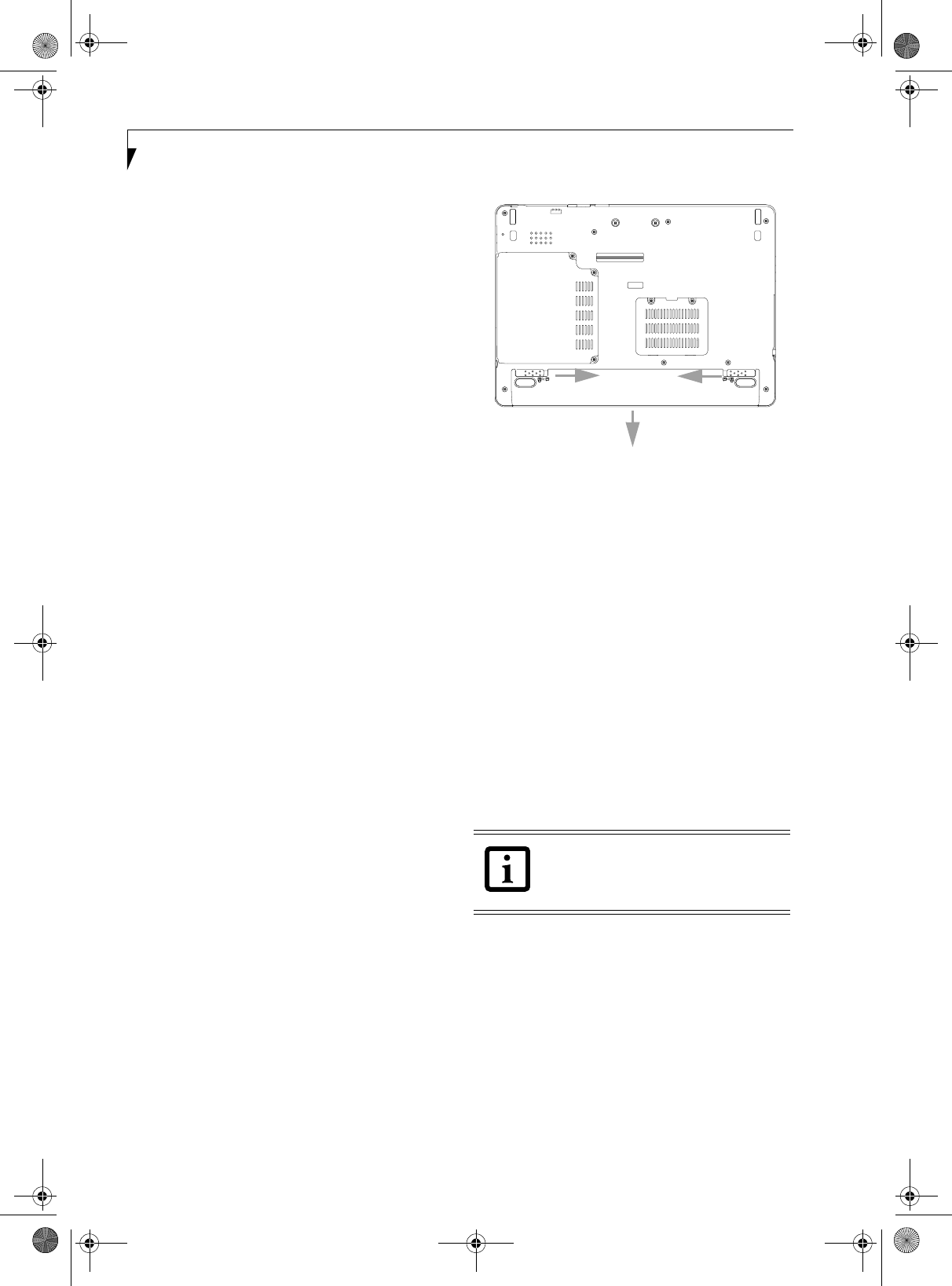
38
LifeBook P Series Notebook - Section Four
Once your notebook goes into Dead Battery Suspend
mode you will be unable to resume operation until you
provide a source of power either from an adapter, or a
charged battery. Once you have provided power, you will
need to press the Suspend/Resume button to resume
operation. In the Dead Battery Suspend mode, your data
can be maintained for some time, but if a power source
is not provided promptly, the Power indicator will stop
flashing and go out, meaning that you have lost the data
that was not stored. Once you provide power, you can
continue to use your notebook while an adapter is
charging the battery.
REPLACING THE BATTERY
Your LifeBook P Series notebook comes with one battery
pack; you might want to consider purchasing a spare. By
keeping a spare battery fully charged, you can immedi-
ately swap with one that is not charged.
There are two ways to swap batteries: cold-swapping and
hot-swapping. Cold-swapping means swapping batteries
when the system has been powered down; hot-swapping
is performed when the system is powered by AC power.
Cold-swapping batteries
To cold-swap batteries in your battery compartment,
follow these easy steps: (Figure 4-1)
1. Have a charged battery ready to install.
2. Shut down your notebook and disconnect the AC
adapter.
3. Lift the display enough to pull the display latch from
the slot.
4. Press the battery release latches to open the
compartment.
5. Remove the battery from the compartment.
6. Slide the new battery into the compartment.
7. Close the compartment and the battery release
latches will click into place.
8. Plug in the AC adapter and turn the power on.
Figure 4-1. Removing the Battery
Hot-swapping Batteries
To hot-swap batteries in your battery compartment
follow these easy steps: (Figure 4-1)
1. Close any open files and put your notebook into
Standby mode.
2. Connect an AC adapter or Auto/Airline power
adapter to provide power to the system.
3. Lift the display enough to pull the display latch from
the slot.
4. Press the battery release latches inward to open the
compartment.
5. Remove the battery from the compartment.
6. Slide the new battery into the compartment.
7. Close the compartment and the battery release
latches will click into place.
8. Press the Suspend/Resume button to return your
notebook to normal operation.
If the Lithium ion battery connector is not
fully seated, you may not be able to use
your notebook or charge your battery.
P Series.book Page 38 Wednesday, July 13, 2005 10:43 AM
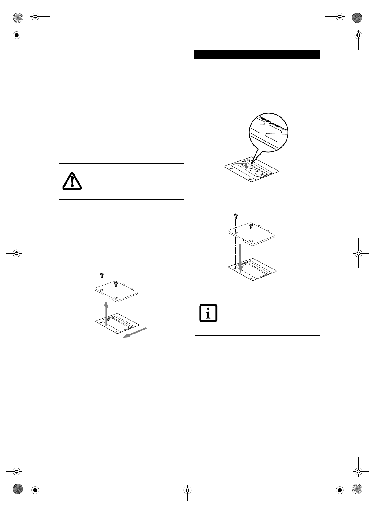
39
User-Installable Features
Memory Upgrade
Module
Your Fujitsu LifeBook P Series notebook comes with a
minimum of 256 MB of high speed Double Data Rate
Synchronous Dynamic RAM 2 (DDR2 SDRAM), 400
MHz factory installed. To increase your system’s memory
capacity, you may install a memory upgrade module. The
memory upgrade must be a dual-in-line (DIMM)
SDRAM module. To ensure 100% compatibility,
purchase the SDRAM module only from the Fujitsu web
store at www.shopfujitsu.com.
INSTALLING MEMORY UPGRADE MODULES
1. Turn off power to your LifeBook notebook and
remove any power adapter (AC or auto/airline).
2. Make sure that all the connector covers are closed.
3. Turn the notebook bottom side up, and remove the
screws of the memory upgrade module compart-
ment. (Figure 4-2)
4. Remove the cover.
Figure 4-2. Opening the Memory Upgrade Compartment
5. Remove the memory upgrade module from the
static guarded sleeve.
6. Align the memory upgrade module with the
component side up. Align the connector edge of the
memory upgrade module with the connector slot in
the compartment. (Figure 4-3)
7. Insert the memory upgrade module at a 45° angle.
Press the connector edge of the module firmly down
and into the connector until it lodges under the
retaining clip. You will hear a click when it is prop-
erly in place.
Figure 4-3. Installing a Memory Module
8. Replace the cover. (Figure 4-4)
9. Replace the screws.
Figure 4-4. Replacing the Memory Compartment Cover
TO REMOVE A MEMORY UPGRADE MODULE
1. Perform steps 1 through 4 of Installing a Memory
Upgrade Module.
2. Pull the clips sideways away from each side of the
memory upgrade module at the same time.
3. While holding the clips out, remove the module
from the slot by lifting it up and pulling towards the
rear of your notebook.
4. Store the memory upgrade module in a static
guarded sleeve.
5. Replace the cover. (Figure 4-4)
6. Replace the screws.
Do not remove any screws from the
memory upgrade module compartment
except those specifically shown in the
directions for installing and removing the
module.
The memory upgrade module is not
something you routinely remove from
your notebook. Once it is installed, you
should leave it in place unless you want to
change system memory capacity.
P Series.book Page 39 Wednesday, July 13, 2005 10:43 AM
40
LifeBook P Series Notebook - Section Four
CHECKING THE MEMORY CAPACITY
Once you have changed the system memory capacity by
either adding or removing a memory upgrade module,
be sure to check that your notebook has recognized the
change.
You can check the memory capacity by clicking [Start]
-> Control Panel, then double-clicking the System icon.
Select the General tab and check the amount of memory
under “Computer.”
The amount of memory displayed should be approxi-
mately the total of all memory modules installed. There
may be a discrepancy of several megabytes which are
allocated for fixed video memory.
Your notebook uses Dynamic Video
Memory Technology (DVMT), which
allows the video driver to dynamically
determine the amount of memory that is
used. Your notebook can use a maximum
of 128 MB of system memory for video
functions.
If the total memory displayed is incorrect,
check that your memory upgrade module
is properly installed. (If the module is
properly installed and the capacity is still
not correctly recognized, see
Troubleshooting on page 52.
P Series.book Page 40 Wednesday, July 13, 2005 10:43 AM
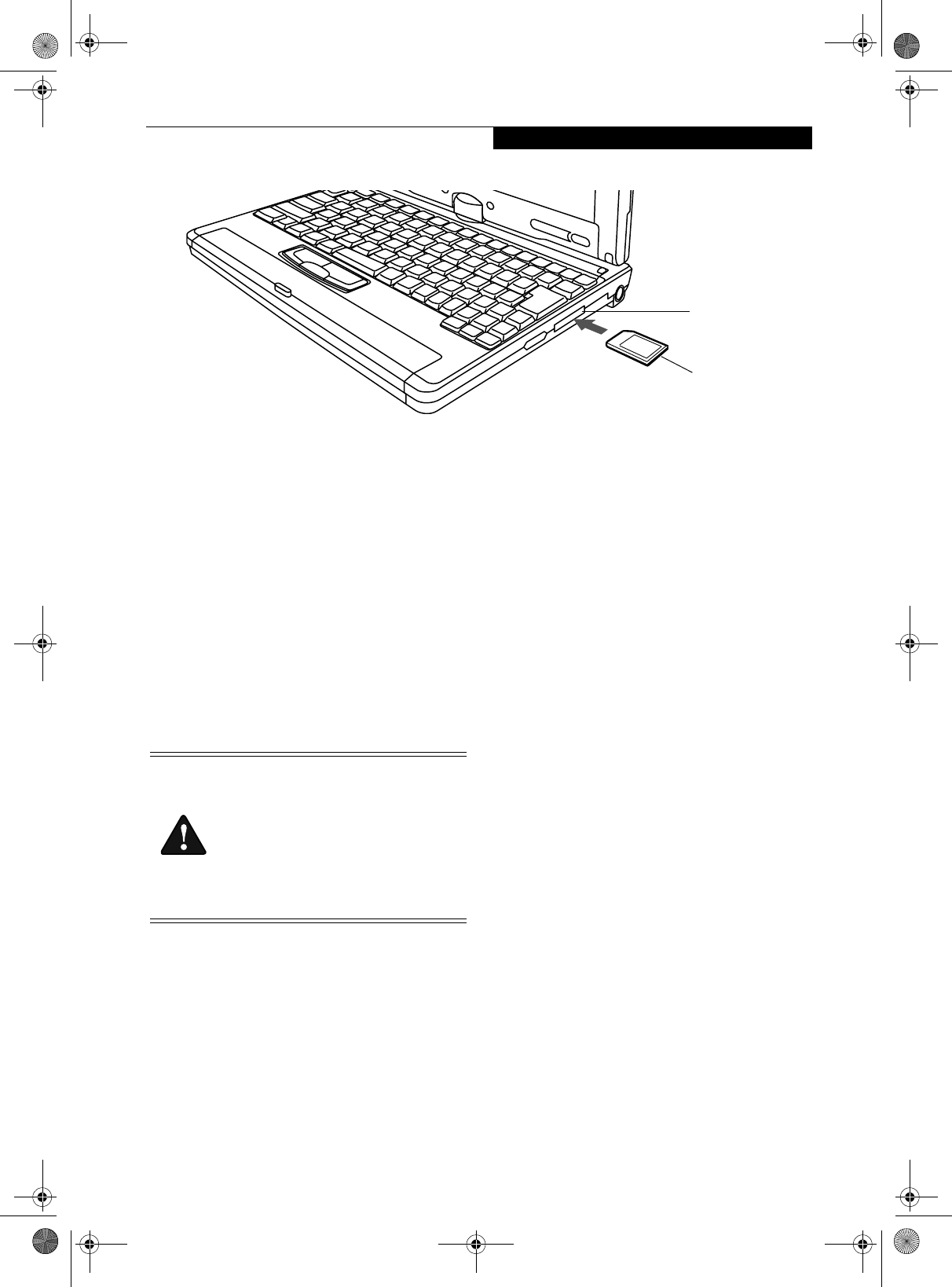
41
User-Installable Features
Figure 4-5. Inserting an SD Card
Secure Digital Media
Your LifeBook notebook supports Secure Digital (SD)
cards, on which you can store and transfer data to and
from a variety of digital devices. These cards use flash
memory architecture, which means they don’t need a
power source to retain data.
Secure Digital (SD) Cards allow portable storage among
a variety of devices, such as cell phones, GPS systems,
digital cameras, and PDAs. SD Cards transfer data
quickly, with low battery consumption. It uses flash
memory architecture.
INSERTING SD CARDS
SD Cards are inserted in the SD Card slot (Figure 4-9).
To insert an SD Card, follow these steps:
1. See your SD Card manual for instructions on the
insertion of your card. Some cards may require that
your notebook is off while inserting them.
2. Make sure there is no card currently in the slot. If
there is, see Removing an SD Card.
3. Insert your card into the slot with the product label
facing up.
4. Push the card firmly into the slot until it is seated in
the connector.
REMOVING AN SD CARD
To remove an SD Card, first see your SD Card manual
for instructions. Some cards may require your LifeBook
notebook to be in Suspend Mode or Off while removing
them. To remove the card from the slot, simply pull it
out.
SD Card Slot
SD Card
■inserting or removing an SD Card during
your LifeBook notebook’s shutdown or
bootup process may damage the card
and/or your LifeBook notebook.
■Do not insert a card into a slot if there is
water or any other substance on the
card as you may permanently damage
the card, your LifeBook notebook, or
both.
P Series.book Page 41 Wednesday, July 13, 2005 10:43 AM
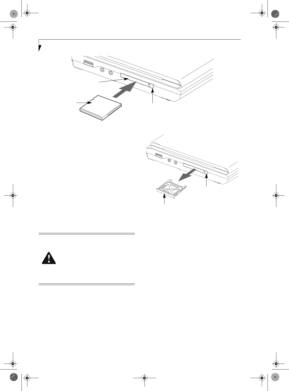
42
LifeBook P Series Notebook – Section Four
Figure 4-6. Compact Flash Card Slot
Compact Flash Cards
Your Fujitsu LifeBook notebook supports Compact
Flash (CF) cards, which can perform a variety of func-
tions.
Some available Compact Flash Cards:
■Memory cards
■Fax/data modem cards
■Local area network (LAN) cards
For further information, refer to the instructions
supplied with your CF Card.
INSERTING COMPACT FLASH CARDS
Compact Flash Cards are inserted in the Compact Flash
Card slot. To insert a Compact Flash Card, follow these
steps: (Figure 4-2)
1. See your Compact Flash Card manual for specific
instructions on the insertion of your card. Some
Compact Flash Cards may require your notebook to
be Off while inserting them.
2. When you receive your LifeBook, there will be a
protective plug inserted in the slot. Whenever you
don’t have a Compact Flash Card inserted, be sure to
replace the plug to prevent system contamination.
To remove the plug, press the Compact Flash Card
eject button. (Figure 4-3)
Figure 4-7. Removing Compact Flash Slot plug
3. When the Compact Flash Slot plug is ejected,
remove it from the slot.
4. Insert your Compact Flash Card into the slot, with
the product label facing up.
5. Push the card into the slot firmly until it is seated
in the opening. You will hear a click and the Eject
button will pop away from your notebook.
Compact Flash Card
Compact Flash Card Slot
Compact
Eject Button
Flash Card
■Inserting or removing a Compact Flash
Card during your LifeBook notebook’s
shutdown or bootup process may dam-
age the card and/or your notebook.
■Do not insert a Compact Flash Card into
a slot if there is water or any other sub-
stance on the card as you may perma-
nently damage the card, your LifeBook
notebook, or both.
Compact Flash Slot Plug
Compact Flash
Card Eject Button
P Series.book Page 42 Wednesday, July 13, 2005 10:43 AM
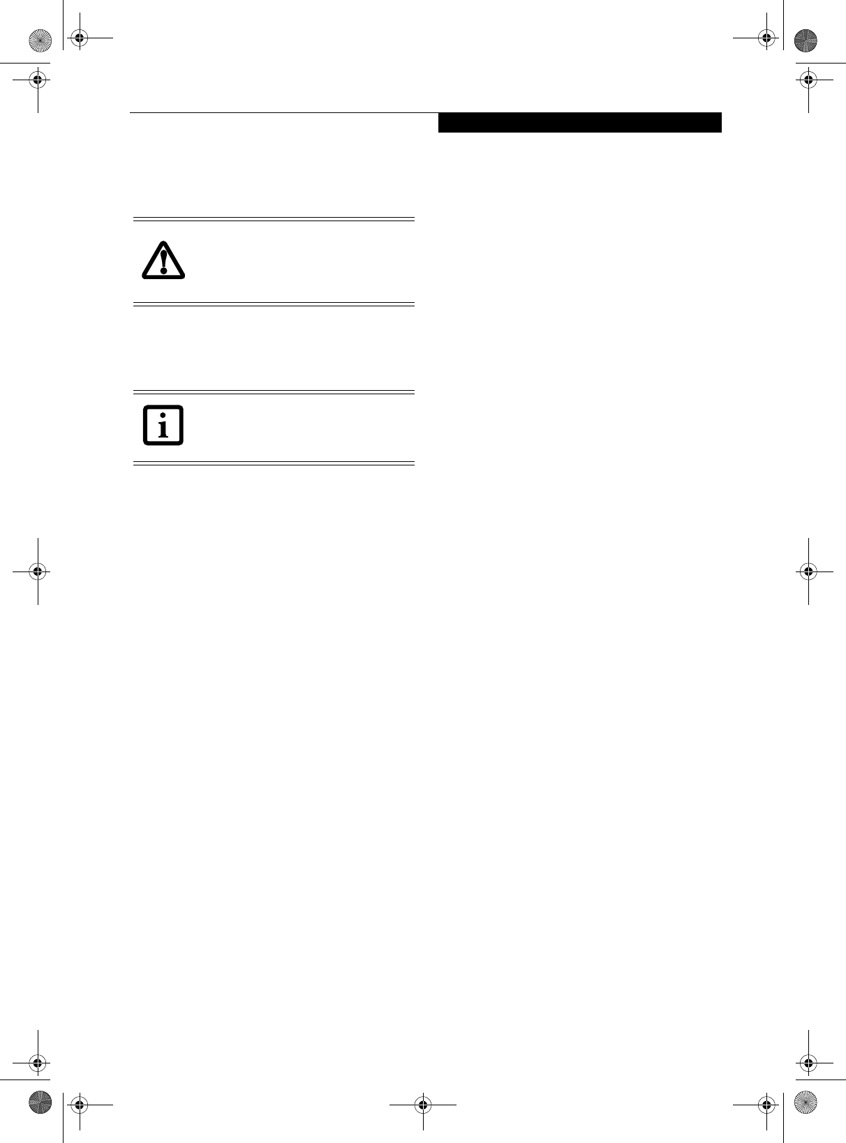
43
User Installable Features
REMOVING COMPACT FLASH CARDS
To remove a Compact Flash Card, follow these easy
steps:
1. See your Compact Flash Card manual for specific
instructions on removing your card. Some Compact
Flash Cards may require your notebook to be in
Suspend Mode or Off while removing them.
2. Push the eject button in until it is flush with the
notebook. This will push the Compact Flash Card
slightly out of the slot allowing you to remove the
card.
Windows has a shutdown procedure for
Compact Flash Cards that must be fol-
lowed before removing a card. (Please
review your operating system manual for
the correct procedure).
If the dialog box states that the device
cannot be removed, you must save all of
your open files, close any open applica-
tions and shut down your notebook.
P Series.book Page 43 Wednesday, July 13, 2005 10:43 AM
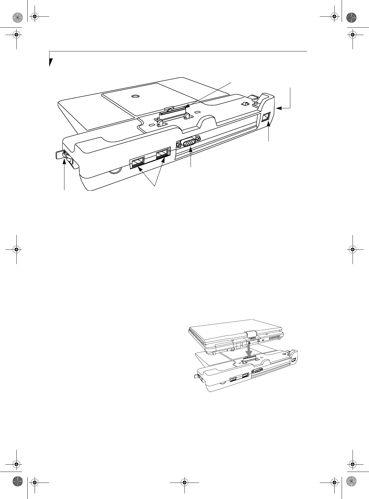
44
LifeBook P Series Notebook - Section Four
Figure 4-8. Port Replicator rear panel
Port Replicator
An optional Port Replicator is available from Fujitsu to
support your LifeBook P Series notebook. The Port
Replicator extends the functionality of your notebook by
providing ports to connect USB devices, an external
monitor, external speaker, or a LAN device. The Port
Replicator connects to the bottom of your notebook. See
“Device Ports” on page 46.
PORT REPLICATOR COMPONENTS
Following is a description of the Port Replicator components.
(Figure 4-11)
DC Power Jack
The DC power jack allows you to plug in the AC adapter to
power your notebook and charge the internal Lithium ion
battery.
USB 2.0 Ports (Qty. 2)
Universal Serial Bus (USB) 2.0 ports allow you to connect USB
devices. USB 2.0 ports are backward-compatible with USB 1.1
devices.
External Monitor Port
The external monitor port allows you to connect an external
VGA or SVGA monitor. Note that if a Port Replicator is
attached, you must use the external monitor port on the Port
Replicator, not the one on your system.
LAN (RJ-45) Jack
The LAN jack allows you to connect a LAN to the Port Repli-
cator. Note that when the system is attached to the Port Repli-
cator, the LAN Jack on the Port Replicator should be used, not
the one on the system.
Docking Port
The docking port connects the Port Replicator to your LifeBook
notebook.
Port Replicator Release Latch
Pull the Port Replicator Release latch away from the Port Repli-
cator to remove the Port Replicator from your notebook.
ATTACHING PORT REPLICATOR
To attach the Port Replicator, align the Port Replicator
connector on the bottom of your notebook with the connector
on the Port Replicator and push the corners down simulta-
neously. (Figure 4-12)
Figure 4-9. Attaching the Port Replicator
DETACHING PORT REPLICATOR
To detach the Port Replicator:
1. Pull the Port Replicator’s release latch away from the Port
Replicator to release it from your notebook. (Figure 4-13)
LAN (RJ-45) Jack
DC Power Jack
USB Ports
External Monitor Port
Port Replicator
Release Latch
Docking Port
P Series.book Page 44 Wednesday, July 13, 2005 10:43 AM
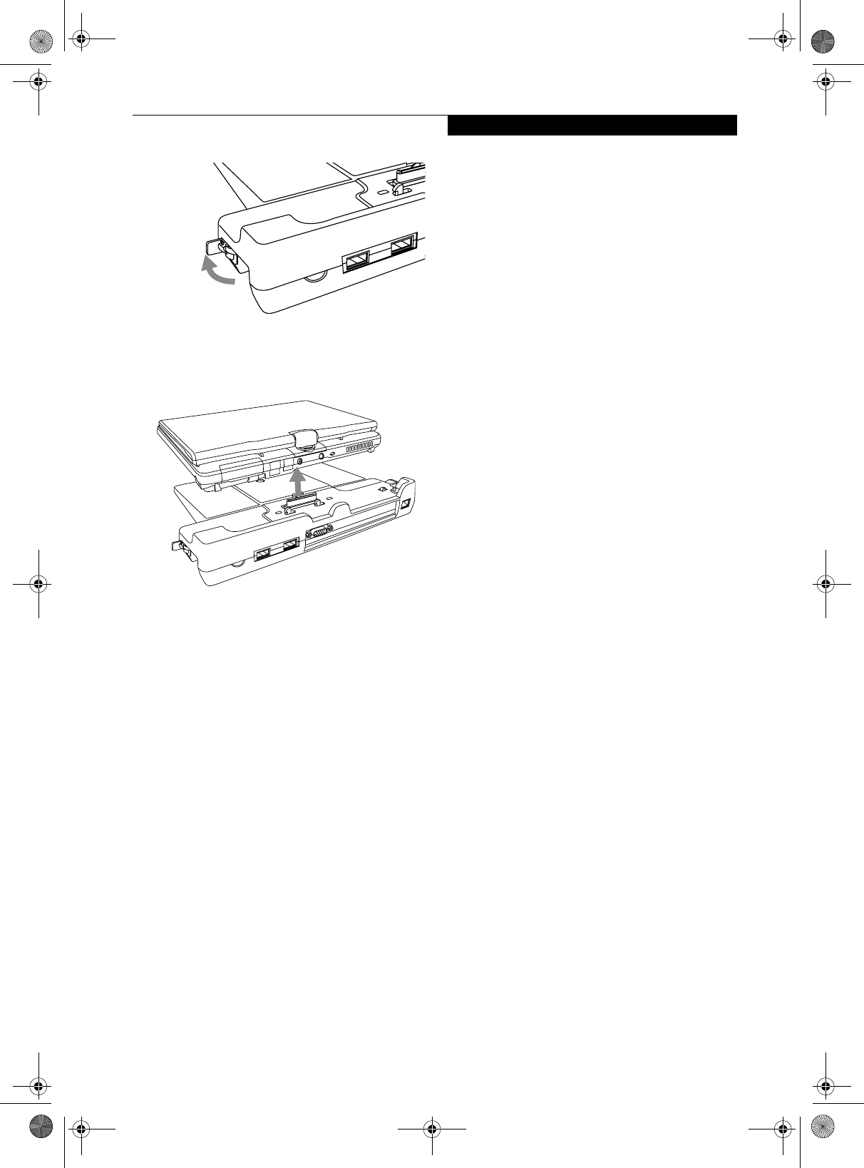
45
User-Installable Features
Figure 4-10. Unlatching the Port Replicator
2. Pull the notebook away from the Port Replicator to detach
it from your notebook. (Figure 4-14)
Figure 4-11. Removing the Port Replicator
P Series.book Page 45 Wednesday, July 13, 2005 10:43 AM
46
LifeBook P Series Notebook - Section Four
Device Ports
Your LifeBook P Series notebook and the optional Port
Replicator come equipped with multiple Device Ports to
which you can connect an external device including: disk
drives, keyboards, modems, printers, etc.
MODEM (RJ-11) JACK
The modem (RJ-11) jack is used for an internal modem.
To connect the telephone cable follow these easy steps:
(See figure 2-7 on page 12 for location)
1. Align the connector with the jack opening.
2. Push the connector into the jack until it is seated.
3. Plug the other end of the telephone cable into a
telephone outlet.
INTERNAL LAN (RJ-45) JACK
The internal LAN (RJ-45) jack is used for an internal 10/
100 BaseTx Ethernet connection. You will need to
configure your notebook to work with your particular
network. (Please refer to your network administrator for
information on your network
configuration.) To connect the LAN cable follow these
easy steps: (See figure 2-7 on page 12 for location)
1. Align the connector with the jack opening.
2. Push the connector into the jack until it is seated.
3. Plug the other end of the cable into a LAN outlet.
DOCKING PORT
The docking port is used for the connection of your
notebook to an optional port replicator. In order to
connect your notebook to one of these devices follow the
instructions that came with your port replicator. (See
figure 2-8 on page 13 for location)
UNIVERSAL SERIAL BUS PORTS
The two Universal Serial Bus 2.0 ports (USB) allow you
to connect USB devices such as external floppy disk
drives, external DVD drives, game pads, pointing
devices, keyboards and/or speakers. USB 2.0 is down-
ward-compatible with USB 1.1 devices, so older USB
devices will work with these ports. USB 2.0 is a much
faster design, running forty times faster than USB 1.1.
In order to connect a USB device, follow these easy steps:
(See figure 2-7 on page 12 for location)
1. Align the connector with the port opening.
2. Push the connector into the port until it is seated.
MICROPHONE JACK
The microphone jack allows you to connect an external
mono microphone. Your microphone must be equipped
with a 1/8”(3.5 mm) mono mini-plug in order to fit into
the microphone jack of your notebook. In order to
connect a microphone follow these easy steps: (See
figure 2-4 on page 9 for location)
1. Align the connector with the port opening.
2. Push the connector into the port until it is seated.
HEADPHONE JACK
The headphone jack allows you to connect headphones
or powered external speakers to your notebook. Your
headphones or speakers must be equipped with a 1/8”
(3.5 mm) stereo mini-plug. In order to connect head-
phones or speakers follow these easy steps: (See figure 2-4
on page 9 for location)
1. Align the connector with the port opening.
2. Push the connector into the port until it is seated.
The internal modem is not intended for
use with Digital PBX systems. Do not
connect the internal modem to a Digital
PBX as it may cause serious damage to the
internal modem or your entire LifeBook P
Series notebook. Consult your PBX
manufacturer’s documentation for details.
Some hotels have Digital PBX systems. Be
sure to find out BEFORE you connect your
modem.
■The internal modem is designed to the
ITU V.90 standard. Its maximum speed
of 53000 bps is the highest allowed by
FCC, and its actual connection rate
depends on the line conditions. The
maximum speed is 33600 bps at upload.
■The internal modem on all LifeBook P
Series notebook’s from Fujitsu Computer
Systems Corporation are certified for use
in the United States and Canada.
■Depending upon the configuration of
your system, your LifeBook notebook
may have either a LAN jack or an IEEE
1394 jack.
Note that the optional Port Replicator is
designed to cover the LAN jack located on
the system. This design ensures that the
LAN jack on the Port Replicator is the only
one used when the Port Replicator is
installed.
P Series.book Page 46 Wednesday, July 13, 2005 10:43 AM
47
User-Installable Features
EXTERNAL VIDEO PORT
The external video port allows you to connect an
external monitor or LCD projector. In order to connect
an external device follow these easy steps: (See figure 2-7
on page 12 for location). There is also an external VGA
monitor on the port replicator (See figure 4-11 on
page 44 for location).
1. Remove the cover from the port opening, if present.
2. Align the connector with the port opening.
3. Push the connector into the port until it is seated.
4. Tighten the two hold-down screws, located on
each side of the connector.
If you plug headphones into the
headphone jack, the built-in stereo
speakers will be disabled.
When an external monitor is plugged in,
pressing the [Fn] + [F10] keys allows you
to change your selection of where to send
your display video. Each time you press the
key combination, you will step to the next
choice, starting with the built-in display
panel only, moving to the external monitor
only, finally moving to both the built-in
display panel and an external monitor.
When an external monitor is plugged in,
pressing the LifeBook Application Panel
Secondary Function buttons (Fn + Screen
Rotation Button) also allows you to
change your selection of where to send
your display video.
P Series.book Page 47 Wednesday, July 13, 2005 10:43 AM

48
LifeBook P Series Notebook - Section Four
P Series.book Page 48 Wednesday, July 13, 2005 10:43 AM

49
5
Troubleshooting
P Series.book Page 49 Wednesday, July 13, 2005 10:43 AM

50
LifeBook P Series Notebook - Section Five
P Series.book Page 50 Wednesday, July 13, 2005 10:43 AM

51
Troubleshooting
Troubleshooting
Your LifeBook P Series notebook is sturdy and subject to
few problems in the field. However, you may encounter
simple setup or operating problems that you can solve
on the spot, or problems with peripheral devices, that
you can solve by replacing the device. The information
in this section helps you isolate and resolve some of
these straightforward problems and identify failures that
require service.
IDENTIFYING THE PROBLEM
If you encounter a problem that you are having diffi-
culty in solving, go through the following procedure
before pursuing further troubleshooting:
1. Turn off your notebook.
2. Make sure the AC adapter is plugged into your note-
book and to an active AC power source.
3. Make sure that any card inserted in the PC Card slot
is seated properly. You can also remove the card
from the slot, thus eliminating it as a possible cause
of failure.
4. Make sure that any devices connected to the external
connectors are plugged in properly. You can also
disconnect such devices, thus eliminating them as
possible causes of failure.
5. Turn on your notebook. Make sure it has been off at
least 10 seconds before you turn it on.
6. Go through the boot sequence.
7. If the problem has not been resolved, refer to the
Troubleshooting Table, that follows, for more
detailed troubleshooting information.
8. If you still have the problem after taking all of the
above approaches, please check our support web site
at http://www.computers.us.fujitsu.com/support
for possible known support issues.
9. If you have tried the solutions suggested in the
Troubleshooting Table and checked our Web site for
possible solutions without success, contact your
support representative:
Toll free: 1-800-8Fujitsu
E-mail: 8fujitsu@us.fujitsu.com
Web site:
http://www.computers.us.fujitsu.com/support
Before you place the call, you should have the following
information ready so that the customer support repre-
sentative can provide you with the fastest possible solu-
tion:
■Product name
■Product configuration number
■Product serial number
■Purchase date
■Conditions under which the problem occurred
■Any error messages that have occurred
■Type of device connected, if any
See the Configuration Label on the bottom of your
notebook for configuration and serial numbers. (See
figure 2-8 on page 13 for location)
SPECIFIC PROBLEMS
Using the Troubleshooting Table
When you have problems with your notebook, try to
find the symptoms under the Problem column of the
troubleshooting table for the feature giving you diffi-
culty.
You will find a description of common causes for that
symptom under the column Possible Cause and what, if
anything, you can do to correct the condition under
Possible Solutions. All possible causes or solutions may
not apply to your notebook.
■If you keep notes about what you have
tried, your support representative may
be able to help you more quickly by giv-
ing additional suggestions over the
phone.
■Do not return a failed notebook to your
supplier until you have talked to a sup-
port representative.
P Series.book Page 51 Wednesday, July 13, 2005 10:43 AM
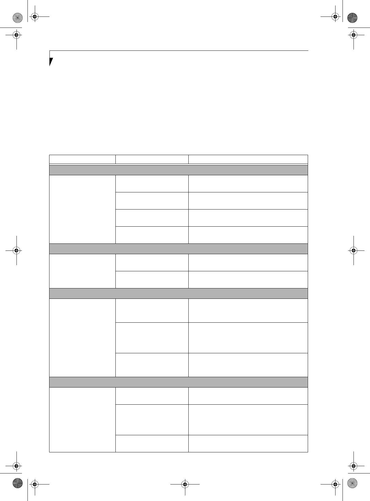
52
LifeBook P Series Notebook - Section Five
TROUBLESHOOTING TABLE
Problem Page
Audio Problems . . . . . . . . . . . . . . . . . . . . . . . . . . page 52
Docking Problems . . . . . . . . . . . . . . . . . . . . . . . . page 52
Hard Drive Problems . . . . . . . . . . . . . . . . . . . . . . page 52
Keyboard or Mouse Problems. . . . . . . . . . . . . . . page 52
Pen Input Problems . . . . . . . . . . . . . . . . . . . . . . . page 53
Memory Problems . . . . . . . . . . . . . . . . . . . . . . . . page 53
Problem Page
Modem Problems. . . . . . . . . . . . . . . . . . . . . . . . . page 53
USB Device Problems . . . . . . . . . . . . . . . . . . . . . page 53
Power Failures . . . . . . . . . . . . . . . . . . . . . . . . . . . page 54
Shutdown and Startup Problems . . . . . . . . . . . . page 55
Video Problems . . . . . . . . . . . . . . . . . . . . . . . . . . page 56
Miscellaneous Problems . . . . . . . . . . . . . . . . . . . page 57
Problem Possible Cause Possible Solutions
Audio Problems
There is no sound coming
from the built-in speakers.
The software volume control is
set too low.
Adjust the sound volume control settings in your
software, operating system and applications.
Headphones are plugged into
your notebook.
Plugging in headphones disables the built-in
speakers, remove the headphones.
Software driver is not config-
ured correctly.
Refer to your application and operating system
documentation for help.
Sound could have been muted
with function keys.
Press [F3] while holding the [Fn] key to toggle the
sound on and off.
Port Replicator Problems
notebook does not turn on
when installed in optional
Port Replicator
Port Replicator AC adapter is
not plugged in.
Provide power to the Port Replicator.
Notebook is not properly
seated in the Port Replicator.
Remove and re-dock your notebook.
Hard Drive Problems
You cannot access your
hard drive.
The setup utility is incorrectly
set for your internal (Primary
Master) hard drive.
Revise BIOS settings to set the Primary Master
correctly. See “BIOS Setup Utility” on page 30.
The wrong drive designator
was used by an application
when a bootable CD-ROM was
used to start the notebook.
Verify drive designator used by application is in
use by the operating system. When the operating
system is booted from a CD, drive designations
are automatically adjusted.
Security is set so your oper-
ating system cannot be started
without a password.
Verify your password and security settings.
Keyboard or Mouse Problems
The built-in keyboard does
not seem to work.
The notebook has gone into
Standby mode.
Push the Suspend/Resume button.
Your application has locked
out your keyboard.
Try to use your integrated pointing device to restart
your system. If this fails, turn your notebook off by
pressing the suspend/resume button for 10 seconds
or more, and then turn it back on.
The NumLock key has been
toggled on.
Press the NumLock key to toggle it off.
P Series.book Page 52 Wednesday, July 13, 2005 10:43 AM

53
Troubleshooting
You have installed an
external keyboard or
mouse, and it does not
seem to work.
Your external device is not
properly installed.
Re-install your device. See “Device Ports” on page 46.
Your operating system soft-
ware is not set up with the
correct driver for that device.
Check your device and operating system docu-
mentation and activate the proper driver.
You have connected an
external keyboard or a
mouse and it seems to be
locking up the system.
Your operating system soft-
ware is not set up with the
correct driver for that device.
Check your device and operating system
documentation and activate the proper driver.
Your system has crashed. Try to restart your notebook. If that fails, turn off
the power by pressing the suspend/resume button
for at least 10 seconds, and then power back on.
Pen Input Problems
Cursor is not tracking the
pen
The system may be
uncalibrated
If the cursor on the screen appears to be misaligned
with the pen or is not accurately tracking the pen,
calibrate the pen. See “Calibrating the Touch
Screen” on page 24.
Memory Problems
Power On screen or Info
menu of BIOS setup utility
information, does not show
the correct amount of
installed memory.
Your memory upgrade module
is not properly installed.
Turn off your notebook. Remove and re-install your
memory upgrade module. See “Memory Upgrade
Module” on page 39.
You have a memory failure. Check for Power On Self Test (POST) messages.
See “Power On Self Test Messages” on page 58.
Modem Problems
Messages about modem
operation.
Messages about modem
operation are generated by
whichever modem application
is in use.
See your application software documentation for
additional information.
Modem does not appear to
work.
Modem may not have been
initialized.
Verify that the modem has been initialized by the
operating system. TO do so, right-click on My
Computer and select the Hardware tab. Click
[Device Manager] and click on the “+” symbol that
appears next to Modems. Verify that your device is
listed as installed.
USB Device Problems
You have installed a USB
device, but your notebook
does not recognize the
device, or the device does
not seem to work properly.
The device is not properly
installed.
Remove and re-install the device. See “Device Ports”
on page 46.
The device may have been
installed while an application
was running, so your notebook
is not aware of its installation.
Close the application and restart your notebook.
Your software may not have
the correct driver active.
See your software documentation and activate the
correct driver.
Your device and another device
are assigned the same I/O
address.
Check all I/O addresses located within the BIOS
setup utility and any other installed hardware or
software to make sure there are no duplications.
Problem Possible Cause Possible Solutions
P Series.book Page 53 Wednesday, July 13, 2005 10:43 AM

54
LifeBook P Series Notebook - Section Five
Power Failures
You turn on your notebook
and nothing seems to
happen.
The installed battery is
completely discharged or there
is no power adapter (AC or
Auto/Airline) installed.
Check the Status Indicator Panel to determine the
presence and condition of the battery. See “Status
Indicators” on page 14. Install a charged battery or a
Power adapter.
The battery is installed but is
faulty.
Use the Status Indicator Panel to verify the presence
and condition of the battery. See “Status Indicators”
on page 14. If a battery is indicating a short, remove
that battery and operate from another power source
or replace that battery.
The battery is low. Check the Status Indicator Panel to determine the
presence and condition of the battery. See “Status
Indicators” on page 14. Use a Power adapter until
the battery is charged.
The AC or auto/airline adapter
is not plugged in properly.
Verify that your adapter is connected correctly. See
“Power Sources” on page 29.
The Power adapter (AC or
auto/airline) is faulty.
Try a different Power adapter or install a charged
optional second battery.
The Power adapter (AC or
auto/airline) has no power
from the AC outlet, airplane
seat jack, or the car’s cigarette
lighter.
Move the AC cord to a different outlet, check for a
line switch or tripped circuit breaker for the AC
outlet. If you are using an auto/airline adapter in a
car make sure the ignition switch is in the On or
Accessories position.
Your notebook turns off all
by itself.
The power management
parameters are set for auto
timeouts which are too short
for your operating needs.
Press any button on the keyboard, or move the
mouse to restore operation. If that fails, push the
Suspend/Resume button. Check your power
management settings, or close your applications
and go to the Power Savings menu of the setup
utility to adjust the timeout values to better suit
your operation needs.
You are operating on battery
power only and have ignored a
low battery alarm until the
battery is at the dead battery
state and your machine has
gone into Dead Battery
Suspend mode.
Install a power adapter and then push the Suspend/
Resume button. See “Power Sources” on page 29.
You have a battery failure. Verify the condition of the battery using the
Status Indicator panel, and replace or remove
any battery that is shorted. See “Status Indicators” on
page 14.
Your power adapter has failed
or lost its power source.
Make sure the adapter is plugged in and the outlet
has power.
Your notebook will not
work on battery alone.
The battery is dead. Replace the battery with a charged one or install a
Power adapter.
No battery is installed. Install a charged battery.
Problem Possible Cause Possible Solutions
P Series.book Page 54 Wednesday, July 13, 2005 10:43 AM

55
Troubleshooting
Your notebook will not
work on battery alone.
(continued)
The battery is improperly
installed.
Verify that the battery is properly connected by
re-installing them.
Your battery is faulty. Verify the battery condition using the Status Indi-
cator panel and replace or remove any battery that is
shorted. See “Status Indicators” on page 14.
The battery seems to
discharge too quickly.
You are running an application
that uses a great deal of power
due to frequent hard drive or
CD-ROM access, or use of a
modem or LAN PC card.
Use a power adapter for this application when at all
possible.
The power savings features
may be disabled.
Check the power management and/or setup utility
settings in the Power Savings menu and adjust
according to your operating needs.
The brightness is turned all
the way up.
Turn down the brightness adjustment. The higher
the brightness the more power your display uses.
The battery is very old. Replace the battery.
The battery has been exposed
to high temperatures.
Replace the battery.
The battery is too hot or too
cold.
Restore the notebook to normal operating tempera-
ture. The Charging icon on the Status Indicator
panel will flash when the battery is outside its
operating range.
The AC Adapter is defective. Replace with another AC Adapter to see if the
problem persists. Replace any defective AC
Adapters.
Shutdown and Startup Problems
The Suspend/Resume
button does not work.
The Suspend/Resume button
is disabled from the Advanced
submenu of the Power menu
of the setup utility.
Enable the button from the setup utility.
You did not hold the button
in long enough.
Hold the button longer. This may need to be a few
seconds if your application is preventing the CPU
from checking for button pushes.
There may be a conflict with
the application software.
Close all applications and try the button again.
The system powers up,
and displays power-on
information, but fails to
load the operating system.
The boot sequence settings of
the setup utility are not
compatible with your
configuration.
Set the operating source by pressing the [F2] key
while the Fujitsu logo is on screen, entering the
setup utility and adjusting the source settings from
the Boot menu. See “BIOS Setup Utility” on page 30.
You have a secured system
requiring a password to load
your operating system.
Make sure you have the right password. Enter the
setup utility and verify the Security settings and
modify them as accordingly. See “BIOS Setup
Utility” on page 30.
Problem Possible Cause Possible Solutions
P Series.book Page 55 Wednesday, July 13, 2005 10:43 AM

56
LifeBook P Series Notebook - Section Five
An error message is
displayed on the screen
during the notebook boot
sequence.
Power On Self Test (POST) has
detected a problem.
See the Power On Self Test (POST) messages to
determine the meaning and severity of the problem.
Not all messages are errors; some are simply status
indicators. See “Power On Self Test Messages” on
page 58.
Your system display won’t
turn on when the system is
turned on or when the
system has resumed.
The system may be password-
protected.
Check the status indicator panel to verify that the
Security icon is blinking. If it is blinking, enter your
password.
Your notebook appears to
change setup parameters
when you start it.
BIOS setup changes were not
saved when you made them
and exited the BIOS setup
utility returning it to previous
settings.
Make sure you select Save Changes And Exit when
exiting the BIOS setup utility.
The BIOS CMOS back-up
battery has failed.
Contact your support representative for repairs.
This is not a user-serviceable part.
Video Problems
The built-in display is blank
when you turn on your
notebook.
The angle of the display and
the brightness settings are not
adequate for your lighting
conditions.
Move the display and the brightness control until
you have adequate visibility.
The optional Port Replicator is
attached, an external monitor
is plugged in, and the note-
book is set for an external
monitor only.
Pressing [F10] while holding down the [Fn] key
allows you to change your selection of where to
send your display video. Each time you press the
combination of keys you will step to the next
choice. The choices, in order are: built-in display
only, external monitor only, both built-in display
and external monitor.
The power management
timeouts may be set for very
short intervals and you failed
to notice the display come on
and go off again.
Press any button the keyboard, or move the mouse
to restore operation. If that fails, push the Suspend/
Resume button. (The display may be shut off by
Standby mode, Auto Suspend or Video Timeout)
The notebook turned on
with a series of beeps and
your built-in display is
blank.
Power On Self Test (POST)
has detected a failure which
does not allow the display
to operate.
Contact your support representative.
Your system display won’t
turn on when the system is
turned on or when the
system has resumed.
The system may be password-
protected.
Check the status indicator panel to verify that the
Security icon is blinking. If it is blinking, enter your
password.
The display goes blank by
itself after you have been
using it.
The notebook has gone into
Video Timeout, Standby
Mode, or Hibernate Mode
because you have not used it
for a period of time.
Press a button on the keyboard, or move the mouse
to restore operation. If that fails, push the Suspend/
Resume button. Check your power management
settings, or close your applications and go to the
Power Savings menu of the setup utility to adjust the
timeout values to better suit your operation needs.
See “BIOS Setup Utility” on page 30.
Problem Possible Cause Possible Solutions
P Series.book Page 56 Wednesday, July 13, 2005 10:43 AM

57
Troubleshooting
The display goes blank by
itself after you have been
using it.
(continued)
The power management time-
outs may be set for very short
intervals and you failed to
notice the display come on
and go off again.
Press any button on the keyboard, or move the mouse
to restore operation. If that fails, push the Suspend/
Resume button. (The display may be shut off by
Standby Mode, Auto Suspend or Video Timeout)
The display does not close. A foreign object, such as a
paper clip, is stuck between the
display and the keyboard.
Remove all foreign objects from the keyboard.
The display has bright or
dark spots.
If the spots are very tiny and
few in number, this is normal
for a large LCD display.
This is normal; do nothing.
If the spots are numerous or
large enough to interfere with
your operation needs.
The display needs technical diagnosis; contact your
support representative.
The application display
uses only a portion of your
screen and is surrounded
by a dark frame.
You are running an application
that does not support 800 x
600/1024 x 768 pixel resolution
display and display compres-
sion is enabled.
When compensation is disabled, a clearer but
smaller display for applications that do not support
800 x 600/1024 x 768 pixel resolution will result. You
can fill the screen but have less resolution by
changing your compensation setting. (See the Video
Features submenu, located within the Advanced
menu of the BIOS. See “BIOS Setup Utility” on
page 30.
You have connected an
external monitor and it
does not display any
information.
Your BIOS setup is not set to
enable your external monitor.
Try toggling the video destination by pressing [Fn]
and [F10] together, or check your BIOS setup and
enable your external monitor. (See the Video
Features submenu, located within the Advanced
Menu of the BIOS. See “BIOS Setup Utility” on
page 30.
Your external monitor is not
properly installed.
Reinstall your device. See “External Video Port” on
page 47.
Your operating system soft-
ware is not set up with the
correct software driver for
that device.
Check your device and operating system
documentation and activate the proper driver.
You have connected an
external monitor and it
does not come on.
Your external monitor may not
be compatible with your note-
book.
See your monitor documentation and the External
Monitor Support portions of the Specifications
section. See “Specifications” on page 71.
Miscellaneous Problems
An error message is
displayed on the screen
during the operation of an
application.
Application software often has
its own set of error message
displays.
See your application manual and help displays
screens for more information. Not all messages are
errors some may simply be status.
Problem Possible Cause Possible Solutions
P Series.book Page 57 Wednesday, July 13, 2005 10:43 AM

58
LifeBook P Series Notebook - Section Five
POWER ON SELF TEST MESSAGES
The following is an alphabetic list of error-and-status
messages that Phoenix BIOS and/or your operating
system can generate and an explanation of each message.
Error messages are marked with an *. If an error message
is displayed that is not in this list, write it down and
check your operating system documentation both on
screen and in the manual. If you can find no
reference to the message and its meaning is not clear,
contact your support representative for assistance.
nnnn Cache SRAM Passed
Where nnnn is the amount of system cache in kilobytes
successfully tested by the Power On Self Test. (This can
only appear if you have an SRAM PC Card installed.)
*Extended RAM Failed at offset: nnnn
Extended memory not working or not configured prop-
erly. If you have an installed memory upgrade module,
verify that the module is properly installed. If it is prop-
erly installed, you may want to check your Windows
Setup to be sure it is not using unavailable memory
until you can contact your support representative.
nnnn Extended RAM Passed
Where nnnn is the amount of memory in kilobytes
successfully tested.
*Failing Bits: nnnn The hex number nnnn
This is a map of the bits at the memory address (in
System, Extended, or Shadow memory) which failed the
memory test. Each 1 (one) in the map indicates a failed
bit. This is a serious fault that may cause you to lose data
if you continue. Contact your support representative.
*Fixed Disk x Failure or Fixed Disk Controller
Failure (where x = 1-4)
The fixed disk is not working or not configured properly.
This may mean that the hard drive type identified in
your setup utility does not agree with the type detected
by the Power On Self Test. Run the setup utility to check
for the hard drive type settings and correct them if
necessary. If the settings are OK and the message appears
when you restart the system, there may be a serious fault
which might cause you to lose data if you continue.
Contact your support representative.
*Invalid NVRAM media type
Problem with NVRAM access. In the unlikely case that
you see this message you may have some display prob-
lems. You can continue operating but should contact
your support representative for more information.
*Keyboard controller error
The keyboard controller test failed. You may have to
replace your keyboard or keyboard controller but may
be able to use an external keyboard until then. Contact
your support representative.
*Keyboard error
Keyboard not working. You may have to replace your
keyboard or keyboard controller but may be able to
use an external keyboard until then. Contact your
support representative.
*Keyboard error nn
BIOS discovered a stuck key and displays the scan code
for the stuck key. You may have to replace your keyboard
but may be able to use an external keyboard until then.
Contact your support representative.
*Operating system not found
Operating system cannot be located on either drive A: or
drive C: Enter the setup utility and see if both the fixed
disk, and drive A: are properly identified and that the
boot sequence is set correctly. Unless you have changed
your installation greatly, the operating system should be
on drive C:. If the setup utility is correctly set, your hard
drive may be corrupted and your system may have to be
re-installed from your back up media.
*Parity Check 1 nnnn
Parity error found in the system bus. BIOS attempts to
locate the address and display it on the screen. If it
cannot locate the address, it displays “????”. This is a
potentially data destroying failure. Contact your
support representative.
*Parity Check 2 nnnn
Parity error found in the I/O bus. BIOS attempts to
locate the address and display it on the screen. If it
cannot locate the address, it displays “????”. This is a
potentially data destroying failure. Contact your
support representative.
*Press <F1> to resume, <F2> to SETUP
Displayed after any recoverable error message. Press
the [F1] key to continue the boot process or the [F2]
key to enter Setup and change any settings.
*Previous boot incomplete –
Default configuration used
Previous Power On Self Test did not complete success-
fully. The Power On Self Test will load default values and
offer to run Setup. If the previous failure was caused by
incorrect values and they are not corrected, the next
boot will likely fail also. If using the default settings does
not allow you to complete a successful boot sequence,
you should turn off the power and contact your support
representative.
P Series.book Page 58 Wednesday, July 13, 2005 10:43 AM

59
Troubleshooting
*Real time clock error
Real-time clock fails BIOS test. May require board
repair. Contact your support representative.
*Shadow RAM Failed at offset: nnnn
Shadow RAM failed at offset nnnn of the 64k block at
which the error was detected. You are risking data
corruption if you continue. Contact your support repre-
sentative.
nnnn Shadow RAM Passed
Where nnnn is the amount of shadow RAM in kilobytes
successfully tested.
*System battery is dead – Replace and run SETUP
The BIOS CMOS RAM memory hold up battery is dead.
This is part of your BIOS and is a board mounted
battery which requires a support representative to
change. You can continue operating but you will have to
use setup utility default values or reconfigure your setup
utility every time you turn off your notebook.
System BIOS shadowed
System BIOS copied to shadow RAM.
*System CMOS checksum bad – run SETUP
BIOS CMOS RAM has been corrupted or modified
incorrectly, perhaps by an application program that
changes data stored in BIOS memory. Run Setup and
reconfigure the system.
*System RAM Failed at offset: nnnn
System memory failed at offset nnnn of in the 64k block
at which the error was detected. This means that there is
a fault in your built-in memory. If you continue to
operate, you risk corrupting your data. Contact your
support representative for repairs.
nnnn System RAM Passed
Where nnnn is the amount of system memory in
kilobytes successfully tested.
*System timer error
The timer test failed. The main clock that operates the
computer is faulty. Requires repair of system board.
Contact your support representative for repairs.
UMB upper limit segment address: nnnn
Displays the address of the upper limit of Upper
Memory Blocks, indicating released segments of the
BIOS memory which may be reclaimed by a virtual
memory manager.
Video BIOS shadowed
Video BIOS successfully copied to shadow RAM.
MODEM RESULT CODES
The operating system and application software that is
factory installed detects the modem characteristics and
provides the necessary command strings to operate the
modem. The internal modem operation is controlled by
generic AT commands from the operating system and
application software. The standard long form result
codes may, in some cases, be displayed on your screen to
keep you informed of the actions of your modem. The
operating system and application software may suppress
display of the result codes.
Examples of result codes are:
■OK
■NO CARRIER
■NO DIALTONE
■CONNECT 53000 (Connection complete
at 53,000 bps.)
■ERROR
■FAX
■RING (This means an incoming call.)
■BUSY
■NO ANSWER
When using the internal modem with applications that
are not factory installed refer to the application
documentation.
P Series.book Page 59 Wednesday, July 13, 2005 10:43 AM
60
LifeBook P Series Notebook - Section Five
Restoring Your
Pre-installed Software
The Drivers and Applications Restore (DAR) CD
contains sets of device drivers and Fujitsu utilities (in
specific directories) that are unique to your notebook
configuration for use as documented below.
Re-Installing Individual Drivers and Applications
The Drivers and Applications CD can be used to selec-
tively re-install drivers and/or applications that may have
been un-installed or corrupted.
To re-install drivers and/or applications:
1. Boot up the system and insert the DAR CD after
Windows has started. A Fujitsu Installer screen is
displayed after the CD is inserted.
2. After reading the License Agreement, click [I agree].
3. A window will appear containing a list of applica-
tions, drivers, and utilities that you can install from
the Drivers and Applications CD.
4. In the list, check off all the components you want to
install. If you want to install all components, click
[Select All]. Clicking [Select All] will select all of the
blue-coded components; you must select grey and
green components separately.
5. Once you have selected the components you wish to
install, click [Install Selected Subsystems]; the
components will be installed.
6. After the components are installed, click [OK], then
click [Yes] when asked if you want to reboot the
system.
RESTORING THE FACTORY IMAGE
The Restore Disc that came with your system contains
two utilities:
■The Recovery utility allows you to restore the original
contents of the C: drive.
■The Hard Disk Data Delete utility on this disc is used
to delete all data on your hard disk and prevent it from
being reused. Do not use the Hard Disk Data Delete
utility unless you are absolutely certain that you want
to erase your entire hard disk, including all partitions.
BOOT Priority Change
Before restoring an image, you must first verify that your
system is set up to boot from the CD drive. To verify/
change the boot-up priority (rather than booting-up
from the hard drive or an external floppy disk drive),
perform the following steps:
1. Start your system and press the [F2] key when the
Fujitsu logo appears. You will enter the BIOS Setup
Utility.
2. Using the arrow keys, go to the Boot menu.
3. Arrow down to the Boot Device Priority submenu.
Press [Enter].
4. If “Optical Media Drive” or “CD-ROM Drive” is not
at the top of the list, arrow down to the drive in the
list, and press the space bar (or the + key) to move it
to the top of the list. (The system attempts to boot
from the devices in the order in which they are
listed.). Note that the BIOS for some systems will
indicate “CD-ROM Drive”, even when a DVD drive
is connected.
5. If you have an external drive connected, proceed to
step 6; otherwise, proceed to step 7.
6. If you have an external drive connected:
If you have access to the internet, visit the
Fujitsu Support web site at http://
www.computers.us.fujitsu.com/support to
check for the most current information,
drivers and hints on how to perform
recovery and system updates. See
“Automatically Downloading Driver
Updates” on page 61.
There may be certain free third-party
applications pre-installed on your system
that are not on the DAR CD. The latest
versions of the applications can be
downloaded from the third-party’s website.
The components listed are color-coded in
terms of their install status. Blue indicates
that the component can be installed. Green
indicates that the component needs to be
installed separately. Grey indicates a
component that is already installed; grey
items can be reinstalled, but prior to
installation you will receive a reminder that
the component is already installed.
• The use of this disc requires that you
have a device capable of reading CDs
attached to your system. If you do not
have a built-in CD player, you will need
to attach an external player. For more
information on available external devices,
visit our Web site at:
www.shopfujitsu.com.
• This disc can only be used with the
system with which it was purchased.
P Series.book Page 60 Wednesday, July 13, 2005 10:43 AM

61
Troubleshooting
• Select the Advanced menu in the BIOS window.
• Scroll down to the USB Features submenu and
press the Enter key to open it.
• If Legacy USB Support is disabled, press the space
bar to enable it.
• Scroll down to SCSI SubClass Support and press
the space bar to enable it.
7. Press [F10], then click on [Yes] to exit the BIOS
Setup Utility and return to the boot process.
After you have changed the boot priority, you can restore
a backup image when you are booting up.
Procedure
1. Turn on the power to your system.
2. Ensure that you have a device that can read CDs
either installed in your system or attached exter-
nally to it.
3. Insert the Restore Disc into the drive tray.
4. Reboot your system.
5. After the system reboots, follow the instructions
that appear to either restore your system image or
erase all data from your hard disk.
AUTOMATICALLY DOWNLOADING
DRIVER UPDATES
Your system has a convenient tool called the Fujitsu
Driver Update (FDU) utility. With FDU, you can choose
to automatically or manually go to the Fujitsu site to
check for new updates for your system.
The FDU icon should appear in the system tray at
the bottom right of your screen (roll the cursor over the
icons to find the correct one). If the FDU icon does not
appear in the system tray, it can be started by going to
[Start] -> All Programs, and clicking on Fujitsu Driver
Update; this will create the icon automatically.
To invoke the FDU menu, right-click on the FDU icon.
The menu contains the following items:
■Check for updates now
Allows for manual driver update search. The first
time it is used, you are prompted to agree to a user
agreement. After clicking on the icon, the FDU auto-
matically connects with the Fujitsu site to check for
updates and downloads them. While downloading,
the icon has a red bar through it, indicating that it
cannot be used while the download is in process.
When the update is complete, a message appears
informing you of the fact.
■Enable Automatic Update Notifications
Automatically searches for new updates on a regular
basis (approximately every 3 days).
■Show update history
Brings up a screen that displays a history of updates
that have been made via the FDU.
■About Fujitsu Driver Update
Displays the FDU version number and copyright
information
■Fujitsu Driver Update Readme
Displays the FDU readme.
P Series.book Page 61 Wednesday, July 13, 2005 10:43 AM

62
LifeBook P Series Notebook - Section Five
P Series.book Page 62 Wednesday, July 13, 2005 10:43 AM