Fujitsu Isotec 001M33331A Dot Matrix Printer User Manual 1 of 3
Fujitsu Isotec Limited Dot Matrix Printer 1 of 3
Contents
- 1. User Manual 1
- 2. User Manual 2
- 3. User Manual 1 of 3
- 4. User Manual 2 of 3
- 5. User Manual 3 of 3
User Manual 1 of 3
FUJITSU DL3750+/3850+
DOT MATRIX PRINTER
USER'S MANUAL

IMPORTANT NOTE TO USERS
READ THE ENTIRE MANUAL CAREFULLY BEFORE USING THIS PRODUCT. INCORRECT USE OF
THE PRODUCT MAY RESULT IN INJURY OR DAMAGE TO USERS, BYSTANDERS OR PROPERTY.
While FUJITSU ISOTEC has sought to ensure the accuracy of all information in this manual, FUJITSU ISOTEC
assumes no liability to any party for any damage caused by any error or omission contained in this manual, its
updates or supplements, whether such errors or omissions result from negligence, accident, or any other cause. In
addition, FUJITSU ISOTEC assumes no liability with respect to the application or use of any product or system
in accordance with descriptions or instructions contained herein; including any liability for incidental or conse-
quential damages arising therefrom. FUJITSU ISOTEC DISCLAIMS ALL WARRANTIES REGARDING THE
INFORMATION CONTAINED HEREIN, WHETHER EXPRESSED, IMPLIED, OR STATUTORY.
FUJITSU ISOTEC reserves the right to make changes to any products described herein without further notice and
without obligation.
Using This Product in High-risk Situations
This product is designed and manufactured for use in standard applications such as office work, personal devices,
household appliances, and general industrial use. This product is not intended for special uses (nuclear-reactor
control in atomic energy facilities, aeronautic and space systems, air traffic control, operation control in mass
transit systems, medical devices for life support, or missile firing controls in weapons facilities) where particu-
larly high reliability requirements exist, where the pertinent levels of safety are not guaranteed, or where a failure
or operational error could threaten a life or cause a physical injury (hereafter referred to as "high-risk" use).
Customers considering the use of this product for high-risk applications must have safety-assurance measures in
place beforehand. Moreover, they are requested to consult our sales representative before embarking on such
specialized use.

User's Manual i
Federal Communications Commission
Radio Frequency Interference Statement
for United States Users
NOTE: This equipment has been tested and found to comply with the limits
for a Class B digital device, pursuant to Part 15B of the FCC Rules. These
limits are designed to provide reasonable protection against harmful
interference in a residential installation. This equipment generates, uses, and
can radiate radio frequency energy and, if not installed and used in accordance
with the instructions, may cause harmful interference to radio
communications. However, there is no guarantee that interference will not
occur in a particular installation. If this equipment does cause harmful
interference to radio or television reception, which can be determined by
turning the equipment off and on, the user is encouraged to try to correct the
interference by one or more of the following measure:
• Reorient or relocate the receiving antenna.
• Increase the separation between the equipment and receiver.
• Connect the equipment into an outlet on a circuit different from that to
which the receiver is connected.
• Consult the dealer or an experienced radio/TV technician for help.
FCC warning: Changes or modifications not expressly approved by the
party responsible for compliance could void the user’s authority to
operate the equipment.
NOTES
1. Testing of this equipment was performed on model number M33331A or
M33333A.
2. The use of a nonshielded interface cable with the referenced device is
prohibited. The length of the parallel interface cable must be 3 meters (10
feet) or less. The length of the optional serial interface cable must be 15
meters (50 feet) or less. The length of the LAN cable must be 100 meters
(330feet) or less.
3. The length of the power cord must be 2 meters (6.6 feet) or less.

User's Manual
ii
Notice for Canadian Users
This class B digital apparatus meets all requirements of the Canadian
Interference-Causing Equipment Regulations.
Cet appareil numérique de la Classe B respecte toutes les exigences du
Règlement sur le matériel brouilleur du Canada.
Notice for German Users
Bescheinigung des Herstellers/Importeurs
Hiermit wird bescheinigt, daß der/die/das
• M33330B
• M33331B
• M33332B
• M33333B
in Übereinstimmung mit den Bestimmungen der
• EN 45014 (CE)
funk-entstört ist.
Der Deutschen Bundesport wurde das inverkehrbringen dieses Gerätes
angezeigt und die Berechtigung zur Überprüfung der Serie auf Einhaltung der
Bestimmungen eingeräumt.
• Maschinenlärminformations-Verordnung-3. GPSGV, 06.01.2004:
Der höchste Schalldruckpegel beträgt 70 dB (A) oder weniger gemäß
EN ISO7779

User's Manual iii
Energy Saving
As an ENERGY STAR® Partner, FUJITSU ISOTEC LIMITED has deter-
mined that this product meets the ENERGY STAR® guidelines for energy
efficiency.
The International ENERGY STAR® Office Equipment Program is an
international program that promotes energy saving through the use of
computers and other office equipments. The program backs the development
and dissemination of products with functions that effectively reduce energy
consumption. It is an open system in which business proprietors can
participate voluntarily. The targeted products are office equipment such as
computers, displays, printers, facsimiles, and copiers. Their standards and
logos are uniform among participating nations.
CE Declaration
This product sold in Europe conforms to the standard in accordance with EC
Directives.

User's Manual
iv
The contents of this manual may be revised without prior notice and without
obligation to incorporate changes and improvements into units already
shipped.
Every effort has been made to ensure that the information included here is
complete and accurate at the time of publication; however, Fujitsu Isotec
Limited cannot be held responsible for errors and omissions.
Printer model specifications differ with the print column (80 or 136) and the
power supply input voltage (100-120 or 220-240 VAC).
C147-E047-01EN July 2004
Copyright © 2004 FUJITSU ISOTEC LIMITED
Printed in Japan. All rights reserved. No part of this manual may be
reproduced or translated, stored in a database or retrieval system, or
transmitted, in any form or by any means, electronic, mechanical,
photocopying, recording, or otherwise, without the prior written permission of
Fujitsu Isotec Limited.
FUJITSU is a registered trademark and Fujitsu Creative Faces is a trademark
of Fujitsu Limited. Centronics is a trademark of Centronics Data Computer
Coporation. IBM PC and IBM Proprinter XL24E are trademarks of
International Business Machines Corporation. ESC/P2 is a trademark of
Seiko Epson Corporation. Microsoft is a registered trademark and MS-DOS
and Windows are trademarks of Microsoft Corporation. Nimbus Sans is a
registered trademark of URW Unternehmensberatung Karow Rubow Weber
GmbH, Hamburg.
Other product names mentioned in this manual may also be trademarks of
their respective companies.
TRADEMARK
ACKNOWLEDGEMENT

User's Manual v
ABOUT THIS MANUAL
Thank you for buying the Fujitsu DL3750+/3850+ dot matrix printer. You
can expect years of reliable service with very little maintenance. This manual
explains how to use your printer to full advantage. It is written for both new
and experienced printer users.
This manual describes how to install, set up, and use your printer and printer
options. It also explains how to keep the printer in good working condition
and what to do should something go wrong. Detailed procedures are provided
for first-time users. Experienced users can skip some of the details, using the
table of contents and chapter introductions to locate information.
This manual has several appendixes, a glossary, and an index. Appendix A
lists supplies and additional documentation and information available from
your dealer or authorized Fujitsu representative. Fujitsu offices are listed at
the end of the manual.
This manual covers model DL3750+, an 80-column printer and model
DL3850+, a 136-column printer. Each model has a 100-120 VAC or 220-240
VAC power supply. A serial interface is a factory option. A LAN card, a user
add-on option, can be installed only on printer models with the Centronics
parallel+USB interfaces. You must specify these when purchasing the printer.
DL3750+/3850+
Basic specifications
Print line at 10 cpi: 80 columns (DL3750+)
136 columns (DL3850+)
Interface: Centronics parallel
Centronics parallel + RS-232C
Centronics parallel + USB + LAN (LAN:use option)
Alternative specification
Power supply: 100–120 VAC or 220–240 VAC
Factory option
RS-232C serial interface (for Centronics parallel model only.
It must be installed by a field engineer.)
User add-on option
LAN card
cpi: characters per inch
PRINTER MODELS AND
OPTIONS

User's Manual
vi
ORGANIZATION This manual is organized as follows:
Quick Reference summarizes everyday printer operations. After you become
familiar with the printer, use this section as a memory aid.
Chapter 1, Introduction, introduces the printer and identifies key features
and options that enhance the printer’s capabilities.
Chapter 2, Setting Up, gives step-by-step procedures for setting up the
printer for immediate use and identifies the main parts of the printer. If this is
your first printer, you should read the entire chapter before attempting to use
the printer.
Chapter 3, Paper Handling, explains how to load and use paper with your
printer.
Chapter 4, Printing, covers basic printing operations. This chapter describes
everyday operations from the printer’s control panel, such as loading paper
and selecting print features, in detail. After you become more familiar with
the printer, use Quick Reference at the beginning of the manual to refresh
your memory as needed.
Chapter 5, Using Setup Mode, describes how to change the printer’s optional
settings, such as print features, hardware options, and top-of-form. Most
settings only affect print features such as the typestyle and page format. Note
that certain settings directly affect hardware and software compatibility. Refer
to this chapter as indicated in Chapter 2 or as required.
Chapter 6, Maintenance, explains basic maintenance procedures for this
printer.
Chapter 7, Trouble-Shooting, describes problem-solving techniques. Before
you contact your dealer for help, check the list of problems and solutions
provided in this chapter.
Chapter 8, Installing Options, describes the options available for the printer
and explains how to install them.

User's Manual vii
At the end of this manual, you will find several appendixes, a glossary, and an
index. Appendix A gives order numbers for printer supplies, options, and
publications. Other appendixes provide additional technical information about
the printer.
Special information, such as warnings, cautions, and notes, are indicated as
follows:
WARNING
A WARNING indicates that personal injury may result if you do not follow a
procedure correctly.
CAUTION
A CAUTION indicates that damage to the printer may result if you do not
follow a procedure correctly.
NOTE
A NOTE provides “how-to” tips or suggestions to help you perform a
procedure correctly. NOTEs are particularly useful for first-time users.
For Experienced Users:
If you are familiar with this printer or with dot matrix printers in general, this
information will help you use the manual effectively.
CONVENTIONS

User's Manual
viii
TABLE OF CONTENTS
Quick Reference ................................................ QR-1
CHAPTER1 INTRODUCTION
Features ..................................................................... 1–1
Options ....................................................................... 1–2
CHAPTER2 SETTING UP Selecting a Good Location .......................................... 2–1
Unpacking the Printer ................................................. 2–3
Checking Options and Supplies ............................. 2–5
Assembling the Printer ................................................ 2–6
Installing the Cut Sheet Stand ................................ 2–6
Installing the Ribbon Cartridge ............................... 2–7
Getting Acquainted With Your Printer ........................ 2–10
Connecting the Power Cord ...................................... 2–11
Testing the Printer (Offline) ....................................... 2–13
Loading Paper for the Self-Test ........................... 2–13
Printing the Self-Test............................................ 2–14
Connecting the Printer to Your Computer.................. 2–19
Selecting a Parallel Interface Cable ..................... 2–19
Selecting a Serial Interface Cable ........................ 2–19
Selecting a USB Cable ........................................ 2–20
Selecting a LAN cable.......................................... 2–20
Connecting the Interface Cable............................ 2–20
Selecting an Emulation ............................................. 2–23
Printing a Sample Page (Online)............................... 2–26
Installing the Printer Driver ........................................ 2–29
CHAPTER3 PAPER HANDLING
Selecting Paper........................................................... 3–1
Overview of Paper Operations .................................... 3–2
Adjusting for Paper Thickness .................................... 3–4
Using Single Sheets.................................................... 3–5
Loading a Single Sheet of Paper............................ 3–5
Adjusting the left margin ........................................ 3–6
Ejecting Single Sheets ........................................... 3–8

Maintenance
User's Manual ix
USING CONTINUOUS FORMS ................................. 3–8
Positioning the Paper Stack ................................... 3–9
Loading Continuous Forms .................................. 3–10
Adjusting the left margin ...................................... 3–11
Adjusting the TEAR OFF position ........................ 3–13
Unloading Continuous Forms .............................. 3–14
Installing the Tractor Unit ..................................... 3–14
Tearing Off Continuous Forms ............................. 3–15
Feeding and positioning paper .................................. 3–16
Line Feed/Form Feed .......................................... 3–16
Micro Feed........................................................... 3–16
Load Position Adjust ............................................ 3–16
Switching Paper Types.............................................. 3–17
Switching to Single Sheets................................... 3–17
Tips on Paper Handling............................................. 3–18
Switching to Continuous Forms ........................... 3–18
General Tips ........................................................ 3–18
Multipart Forms.................................................... 3–18
Envelopes ............................................................ 3–19
Labels .................................................................. 3–19
CHAPTER4 PRINTING
Selecting Print Features .............................................. 4–1
Using Commercial Software ....................................... 4–2
Using the Control Panel ......................................... 4–2
Selecting MENU1 or MENU2 ................................. 4–3
Starting or Stopping Printing........................................ 4–5
Starting Printing...................................................... 4–5
Stopping Printing .................................................... 4–5
Resuming from a Paper-Out .................................. 4–5
Printing the remaining lines on a page ................... 4–6
Continuing printing after supplying paper ............... 4–6
Resuming after an Area Over warning ................... 4–7
Removing Printed Pages ............................................ 4–8
Removing Single Sheets ............................................. 4–8
Removing Continuous Forms ................................ 4–8
Clearing the Print Buffer .............................................. 4–8

User's Manual
x
CHAPTER5 USING SETUP MODE
How to Use This Chapter ............................................ 5–1
Entering Setup Mode .................................................. 5–2
Overview of Setup Mode ............................................. 5–4
Setup Mode Example............................................. 5–6
Points to Remember .............................................. 5–9
Printing a List of Selected Options ............................ 5–10
Deciding Which Options to Change .......................... 5–12
Changing MENU1 and MENU2 Options ................... 5–14
Procedure ............................................................ 5–27
Resetting MENU1 and MENU2 ............................ 5–28
Changing Hardware Options ..................................... 5–29
Procedure ............................................................ 5–34
Changing Print Position Adjustment Options ............. 5–35
Procedure ............................................................ 5–39
Changing Configuration Options ............................... 5–40
Procedure ............................................................ 5–47
Exiting and Saving .................................................... 5–48
Procedure ............................................................ 5–48
Resetting Defaults..................................................... 5–49
Resetting Power-On Defaults............................... 5–49
Resetting Factory Defaults ................................... 5–49
Resetting Factory Defaults in
MENU1 and MENU2...
5–49
Using the Diagnostic Functions................................. 5–50
Printing the Self-Test............................................ 5–51
Procedure ............................................................ 5–51
Printing Hex Dumps ............................................. 5–52
Procedure ............................................................ 5–53
Checking Vertical Print Alignment (V-ALMNT) ..... 5–55
Procedure ............................................................ 5–55
Setup Mode Reference ............................................. 5–57
DPL24C Plus Organization .................................. 5–58
Differences in IBM Proprinter XL24E Emulation... 5–60
Differences in Epson ESC/P2 Emulation ............. 5–61
Online Setup Mode ................................................... 5–62

Maintenance
User's Manual xi
CHAPTER6 MAINTENANCE
Cleaning...................................................................... 6–1
Cleaning and Vacuuming the Printer ...................... 6–1
Cleaning the Platen and Exit Rollers ...................... 6–3
Replacing the Ribbon.................................................. 6–3
Replacing the Print Head ....................................... 6–7
CHAPTER7 TROUBLE-SHOOTING
Solving Problems ........................................................ 7–1
Print Quality Problems ........................................... 7–1
Paper Handling Problems ...................................... 7–4
Tips for Clearing a Jammed Sheet from the Printer .........
7–6
Operating Problems ............................................... 7–7
Printer Failures ...................................................... 7–9
Diagnostic Functions................................................. 7–10
Getting Help .............................................................. 7–10
CHAPTER8 INSTALLING OPTIONS ....................................................... 8-1
APPENDIX A SUPPLIES AND OPTIONS
Supplies ......................................................................A–1
Option .........................................................................A–1
APPENDIX B PRINTER AND PAPER SPECIFICATIONS
Physical Specifications ................................................B–1
Functional Specifications ............................................B–2
Performance Specifications ........................................B–4
Paper Specifications ...................................................B–6
Print Area ...............................................................B–6
Paper Thickness ....................................................B–8
APPENDIX C COMMAND SETS
Fujitsu DPL24C PLUS ............................................... C–2
Factory Default Settings...................................... C–15
IBM Proprinter XL24E Emulation ............................. C–18
Epson ESC/P2 Emulation ........................................ C–23

User's Manual
xii
APPENDIX D INTERFACE INFORMATION
Parallel Interface ........................................................ D–1
Compatible Mode.................................................. D–2
Nibble Mode.......................................................... D–4
Data Transmission Timing .................................... D–6
Serial Interface........................................................... D–7
Serial Options ....................................................... D–8
Cable Wiring ......................................................... D–8
Serial Protocols................................................... D–10
USB Interface ...........................................................D–11
Specification........................................................ D–11
LAN Interface ........................................................... D–12
APPENDIX E COMMAND SETS
Character Sets 1and 2
(DPL24C PLUS and IBM XL24E Emulation) ............E–1
Italic and Graphics Character Sets
(ESC/P2 Emulation) .................................................E–2
National Character Sets
(All Emulations) .......................................................E–4
National Character Sets
(DPL24C PLUS and IBM XL24E Emulation) .........E–15
National Character Sets
(ESC/P2 Emulation) ..............................................E–16
National Character Sets and Supported Resident Fonts
(All Emulations) ....................................................E–20
APPENDIX F RESIDENT FONT .............................................................. F-1
GLOSSARY OF TERMS ....................................................................... GL-1
INDEX .................................................................................................... IN-1
QUICK REFERENCE
User's Manual QR-1
Quick
Reference Introduction Setting Up Paper
Handling Printing Setup Mode
QUICK REFERENCE
Quick Reference is written for experienced users —
users who are familiar with how the printer works,
but who may need to refresh their memory
occasionally. Only the printer’s normal (non-setup)
mode is covered. For details on setup mode, see Chapter 5.
Normal mode operation includes everyday operations, such as paper handling
and font selection. The printer comes up in normal mode when turned on. To
enter setup mode, press the TEAR OFF and ONLINE buttons at the same time
while the ONLINE indicator is off (not lit).
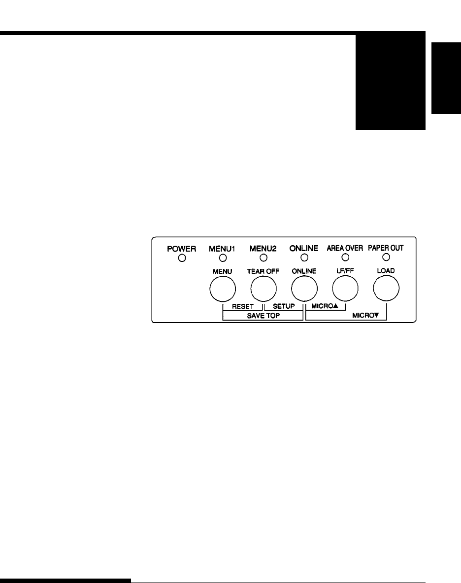
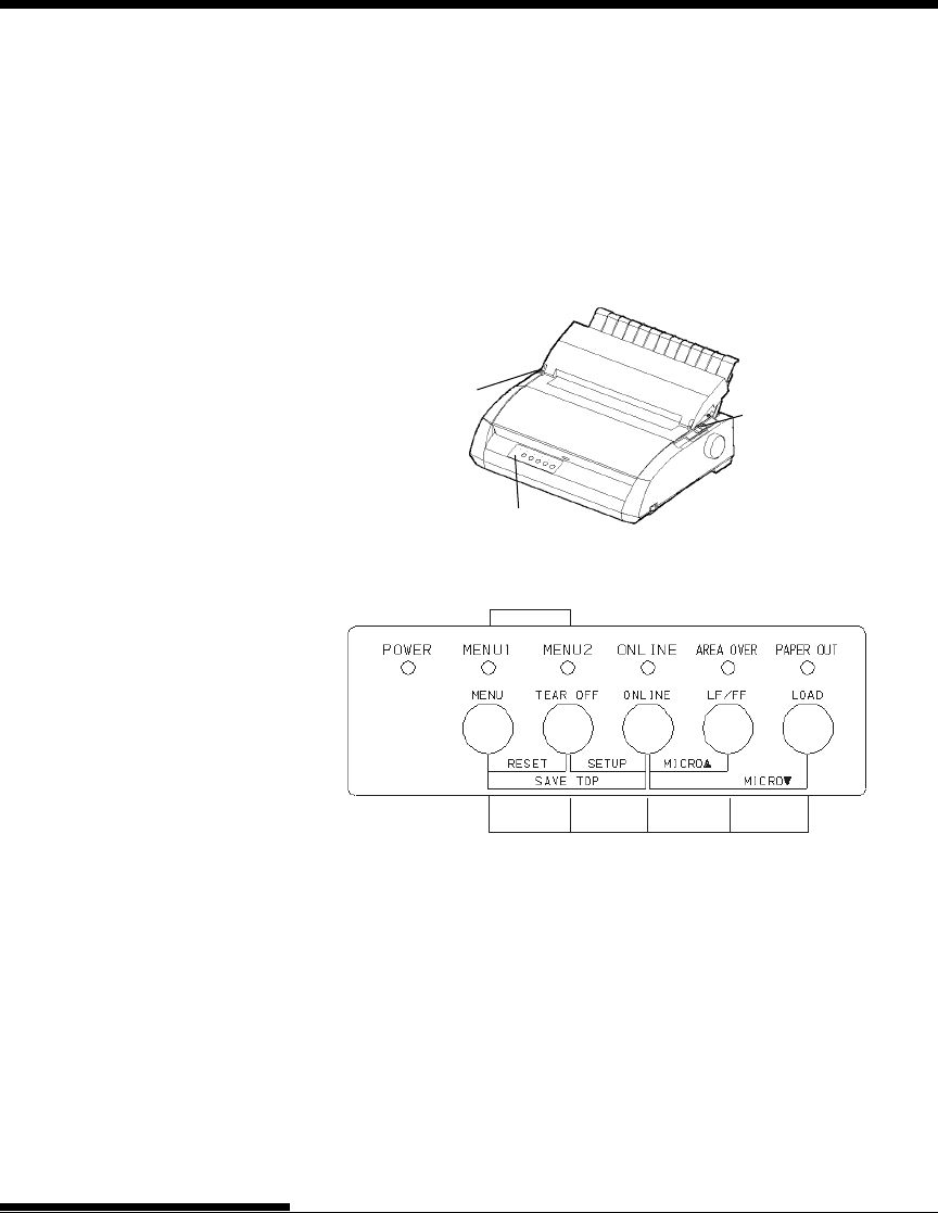
Control panel
The table on the next page lists normal mode operations with online
and offline conditions and gives the required user response.
Operations are listed alphabetically.
Q
QUICK REFERENCE
QR-2 User's Manual
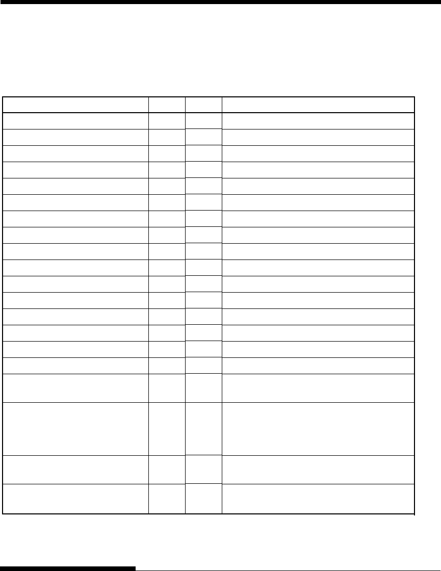
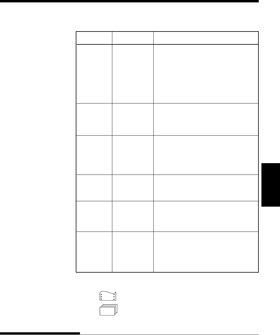
Printer Operations (Normal Mode)
√: Operation can be performed when the printer is in this state.
— : Operation cannot be performed when the printer is in this state.
N/A : Does not apply.
Operation
Clear print buffer
Eject single sheets
Enter normal mode
Enter setup mode
Exit to normal mode
Form feed (forward)
Line feed (forward)
Load paper
Micro feed (backward)
Micro feed (forward)
Place printer offline
Place printer online
Reset power-on defaults
Resume printing after paper end
Save adjusted load positions
Select MENU1 or MENU2
Start/stop/resume printing
Self-test printing
Tear off forms
(Continuous forms only)
Unload paper to park position
(Continuous forms only)
Required Response
Press MENU and TEAR OFF.
Press LF/FF.
Turn printer on. (Press | on the power switch.)
Press TEAR OFF and ONLINE.
Press ONLINE, then press TEAR OFF or MENU.
Press and hold LF/FF until the operation starts.
Press LF/FF within three seconds.
Press LOAD.
Press ONLINE and LOAD.
Press ONLINE and LF/FF.
Press ONLINE.
Press ONLINE.
Turn printer off, then on.
Press ONLINE.
Press ONLINE and MENU.
Press MENU.
Start: Send print command.
Stop/resume: Press ONLINE.
Start: Turn printer off. Press LF/FF while
turning printer on.
Pause/resume: Press TEAR OFF .
Exit: Press ONLINE.
Press TEAR OFF. Tear off forms, then
press any button to retract forms.
Press LOAD.
Online
—
√
N/A
—
—
√
√
√
—
—
√
—
√
—
—
—
√
√
√
√
Offline
√
√
N/A
√
√
√
√
√
√
√
—
√
√
√
√
√
√
√
√
√
1-1
INTRODUCTION
User's Manual
Quick
Reference Introduction Setting Up Paper
Handling Printing Setup Mode
1
INTRODUCTION
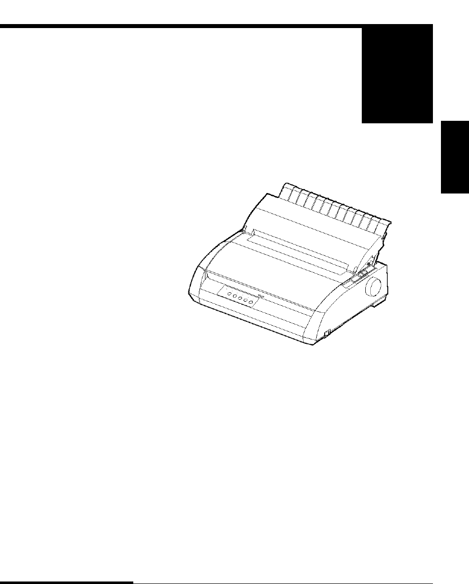
Congratulations on purchasing this printer. This
printer is a compact, versatile printer that offers
maximum compatibility with today’s software
packages and personal computers.
The 24-wire print head provides crisp, clear printing for business, office, and
home environments. This printer is also easy to install and use.
Dot matrix printer
Key printer features and options are listed in the next two sections.
•Software compatibility. This printer, which operates primarily
with the Fujitsu DPL24C PLUS command set, is compatible with the IBM
Proprinter XL24E command set and the Epson ESC/P2 command set.
•Various character sets. As basic character sets, IBM PC character sets 1
and 2 are available for the Fujitsu DPL24C PLUS command set and the
IBM Proprinter XL24E emulation, and the italic character set and graphics
character sets 1 and 2 are available for the Epson ESC/P2 emulation. As
national character sets, a total of 57 or 61 national character sets
(depending on the emulation), including IBM PS/2 character sets, are
available.
FEATURES

1-2
INTRODUCTION
User's Manual
•Multiple fonts. The printer has nineteen resident fonts: Ten bit-map
fonts -- Courier 10, Pica 10, Prestige Elite 12, Boldface PS, OCR-B 10,
OCR-A 10, Correspondence, Compressed, Draft, and High-speed Draft
and nine outline fonts -- Timeless, Nimbus Sans, and Courier, each in
upright, italic, and bold.
•High-speed printing. At 10 cpi, print speed ranges from 113 cps for
letter quality to 400 cps (80-column printer) or 448cps (136-column
printer) for high-speed draft quality.
•Large print buffer. 128K bytes are available in total for storing input
data and downloading fonts. A large input data buffer allows you to send
files to the printer and return quickly to work in your application. A large
download buffer allows you to use custom fonts.
•80-column or 136-column print line. 80-column printers are the most
suitable for printing in landscape mode using letter- or A4- size paper.
136-column printers are the most suitable for printing in landscpe mode
using legal- or standard-size computer forms.
•Simple switching of paper types. The ability to "park" continuous forms
makes it easy to switch between continuous forms and single sheets.
•Auto tearoff. Continuous forms are fed automatically up to the tear-off
position at the end of each job.
•Maintenance-free. The printer only requires periodic cleaning and
changing of the ribbon cartridge.
A LAN card is available as a printer add-on option. A user installable
function, the LAN card can be installed only on printer models with the
Centronics parallel + USB interfaces.
For details, see Chapter 8.
OPTIONS

SETTING UP
User's Manual 2-1
Quick
Reference Introduction Setting Up Paper
Handling Printing Setup Mode
2
SETTING UP
Your new printer is easy to install and set up.
This chapter tells you how to set up the printer
and start printing right away. If this is your first
printer, you should read the entire chapter before
attempting to use the printer.
In this chapter, you will learn how to:
• Unpack, assemble, and select a good location for the printer
• Identify the printer’s major parts
• Connect the power cord and the interface cable
• Test the printer before connecting it to your computer
• Select an emulation and print a sample page using your software
• Installing the printer driver
If you have a problem while setting up the printer, review the section Solving
Problems in Chapter 7. If the problem persists, contact your dealer.
This printer is suitable for most business, office, and home environments. To
obtain peak performance from the printer, select a location that meets the
following guidelines:
√Place the printer on a sturdy, level surface.
√Place the printer near a well-grounded AC power outlet.
√Ensure easy access to the front and rear of the printer by leaving
several inches of space around the printer. Do not block the air vents
on the front, left, and right sides of the printer.
√Do not place the printer in direct sunlight or near heaters.
√Make sure that the room is well-ventilated and free from excessive
dust.
SELECTING A GOOD
LOCATION

SETTING UP
2-2 User's Manual
√Do not expose the printer to extremes of temperature and humidity.
√Use only the power cord supplied with the printer or recommended by
your dealer. Do not use an extension cord.
√Do not plug the printer into a power outlet that is shared with heavy
industrial equipment, such as motors, or appliances, such as copiers or
coffee makers. Such equipment often emits electrical noise or causes
power degradation.
SETTING UP
User's Manual 2-3
Quick
Reference Introduction Setting Up Paper
Handling Printing Setup Mode
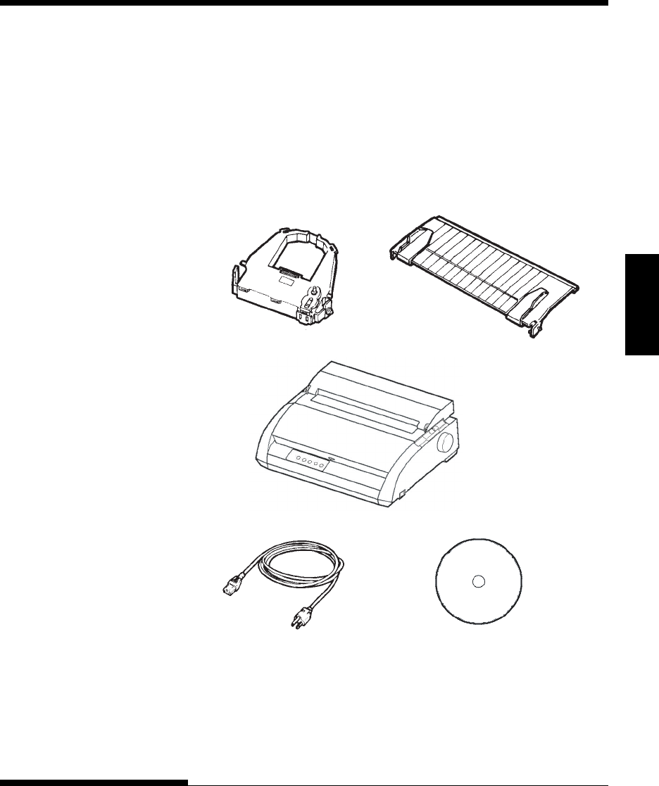
UNPACKING THE PRINTER Unpack the printer as follows:
1. Open the carton and remove the printer and its components. Make
sure that you have all of the items shown below. Note that the power
cord supplied depends on the printer model (100-120 or 220-240 VAC
power supply).
Ribbon cartridge
(Black)
Cut sheet stand
Printer
Power cord Setup disk
Checking items received
SETTING UP
2-4 User's Manual
2. Carefully examine each item for damage. Report any problems to your
dealer or shipping agent.
3. Place the printer where you plan to use it.
4. Remove the tapes securing the front cover, ejection cover, and back
cover. Open the front cover and remove the shipping restraint
cardboard that holds the print head carriage in place (shown below).
Removing the shipping restraint cardboard
Front cover
Cardboard
5. Store the original shipping carton and packaging materials for future
use. For example, the original packaging is ideal for use when you
move or ship your printer to another location.
NOTE
The interface cable is not included with the printer. You must purchase it
separately. Connection of the interface cable is described later in this
chapter.

SETTING UP
User's Manual 2-5
Quick
Reference Introduction Setting Up Paper
Handling Printing Setup Mode
Checking Options and Supplies
The following options and supplies, if ordered, are shipped separately:
• LAN card (user installable option)
• Extra monochrome ribbon cartridge
The RS-232C serial interface is a factory option. It must be installed by a field
engineer. If you ordered a printer with the interface, the board is already
installed in the printer.
Make sure that you received all the options you ordered.
Once you are sure you have everything, you are ready to assemble the printer.
SETTING UP
2-6 User's Manual
ASSEMBLING THE PRINTER
This section explains how to install the cut sheet stand and ribbon cartridge.
Installing the Cut Sheet Stand
The cut sheet stand enables smooth feeding of both single sheets and continu-
ous forms. Install the cut sheet stand as described below:
1. Referring to the following figure, locate the two grooved notches on
the top of the printer, behind the top cover. Note that each notch has a
front groove and a rear groove.
2. Locate the two mounting pins on each side of the cut sheet stand.
Installing the cut sheet stand
Cut sheet stand
Mounting pins
SETTING UP
User's Manual 2-7
Quick
Reference Introduction Setting Up Paper
Handling Printing Setup Mode
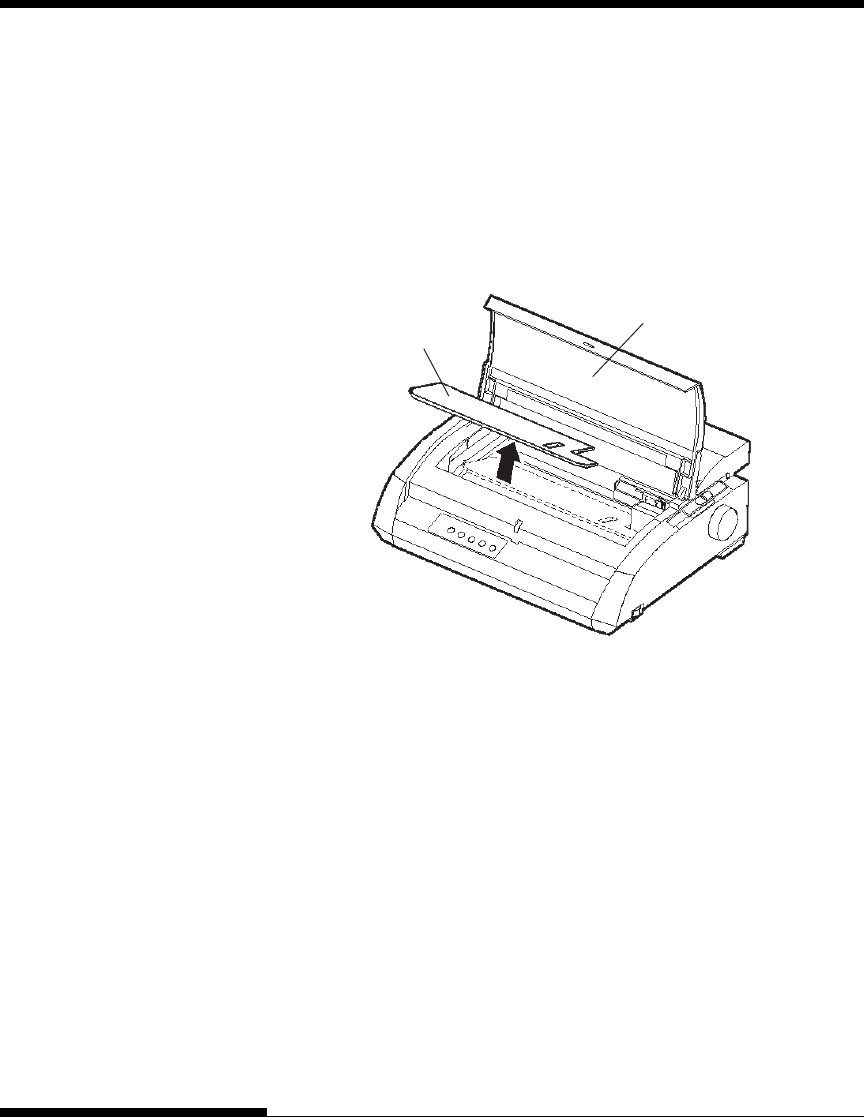
3. Hold the cut sheet stand at an angle over the top of the printer. Slide
the mounting pins into the long, front grooves of the notches. This is
the cut sheet stand's up position, used for printing single sheets.
To rotate the cut sheet stand to its down position, grasp it at the sides
and lift it up until the two upper mounting pins clear the front notches.
Rotate the cut sheet stand backward to place the upper mounting pins
in the rear grooves.
Installing the Ribbon Cartridge
The printer uses a black ribbon cartridge. To install the ribbon cartridge:
1. Turn the printer off. Open the front cover of the printer. For easy
installation, slide the print head carriage so that it does not face a bail
roller.
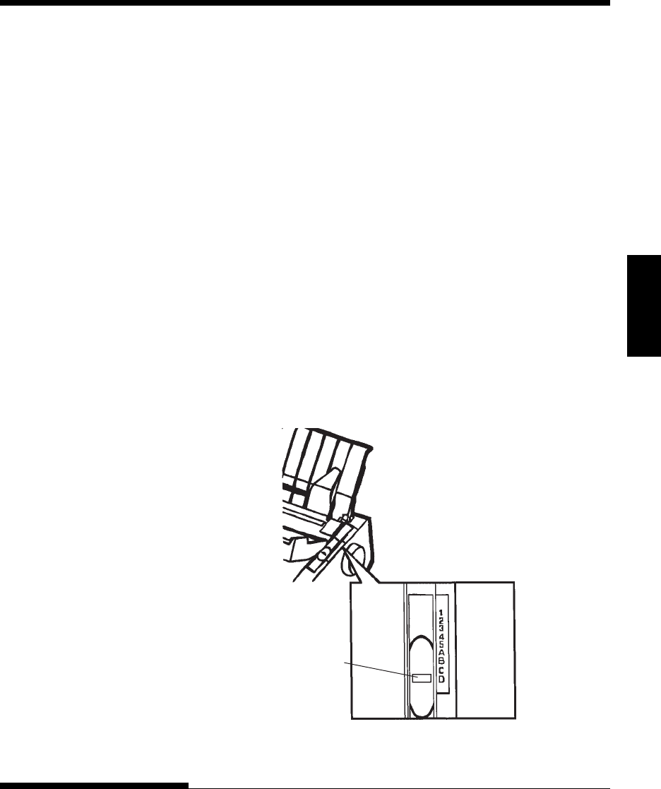
2. The paper thickness lever, located on the right of the printer, has nine
positions. Before you install the ribbon cartridge, move this lever to D.
Preparing to install the ribbon
Paper thickness leve
r
Move to D.
SETTING UP
2-8 User's Manual
CAUTION
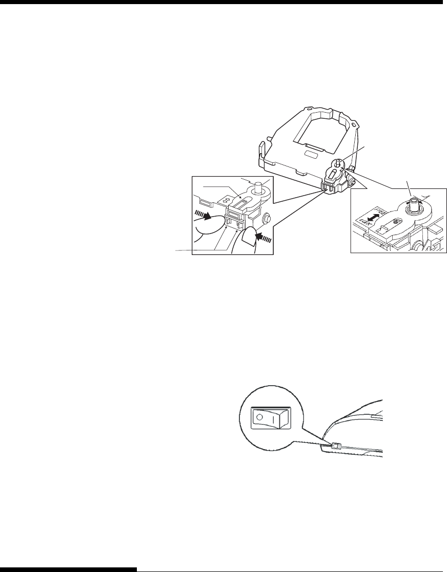
Do not turn the ribbon feed knob in counterclockwise direction.
4. Verify that the power to the printer is off.
(Make sure that the circle mark on the power switch is pressed.).
Installing the ribbon cartridge
5. Move the paper thickness lever to the D position.
6. Open the front cover.
Turn the knob
clockwise.
3. Using the procedure below, release the roller from the LOCK position
and turn the ribbon feed knob clockwise to take up any ribbon slack.
Push in the gray ribbon release tabs on the side of the ribbon cartridge
to release them, and slide the roller from the LOCK position to the
FREE position.
Ribbon feed knob
Preparing the ribbon cartridge
Roller
Release
tabs
SETTING UP
User's Manual 2-9
Quick
Reference Introduction Setting Up Paper
Handling Printing Setup Mode
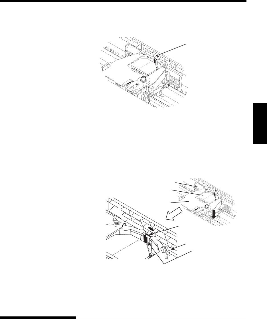
7. Align the print head position with the dot mark (green) on the printer
ejection cover.
Dot mark (green)
WARNING
Avoid touching the print head while using or immediately after using the
printer, as doing so may lead to burns. Wait until the print head cools
down before touching it.
8. Thread the ribbon between the print head and the print guide, then
gently press down on the ribbon cartridge against the printer until it
clicks into place.
(Make sure that the ribbon feed knob is facing upward.)
Print guide
Print head
Ribbon
Print guide
Tip of print head
Ribbon cartridge
9. Turn the ribbon feed knob clockwise to take up any ribbon slack.
10. After the ribbon cartridge has been installed in the printer, adjust the
paper thickness lever to match the thickness of the paper and the
number of sheets of paper to be used
For information about the paper thickness lever, see the section
entitled Adjusting the Paper Thickness in Chapter 3.
SETTING UP
2-10 User's Manual
GETTING ACQUAINTED
WITH YOUR PRINTER
Now that your printer is assembled, take a moment to become familiar with its
major parts.
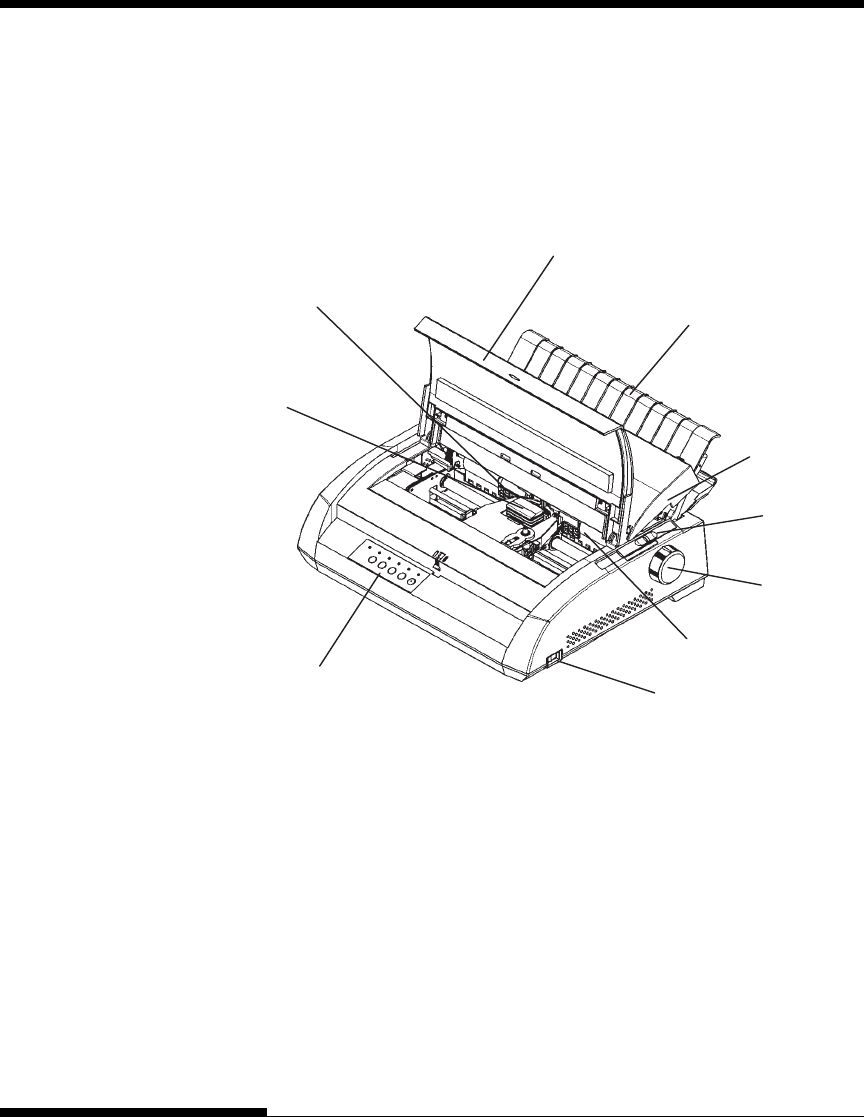
Looking at the printer from the front right side, you can see the parts of the
printer shown in the figure below.
Printer components (front and right)
The printer control panel has the buttons and indicators used to load and feed
paper (see Chapter 3) and select print features (see Chapter 4). The control
panel also allows you to change the printer’s optional settings (see Chapter 5).
Print head
Print guide
Front cover
Cut sheet
stand
Paper
thickness
lever
Platen knob
Platen
Power switch
Control panel
Acounstic
cover
SETTING UP
User's Manual 2-11
Quick
Reference Introduction Setting Up Paper
Handling Printing Setup Mode
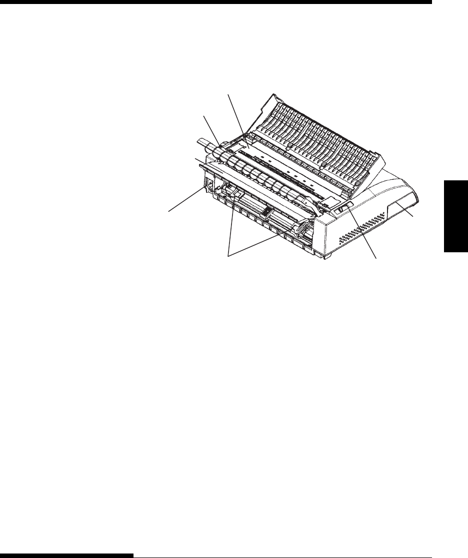
Looking at the printer from the back with the cut sheet stand and back cover
removed, you can see the following parts of the printer:
Ejection cover
Interface
connecto
r
Paper select lever
Power
connector
Forms tractors
Back cover
Paper guide
Printer components (rear)
Before you plug in the printer:
√Make sure that the printer power is switched off. The side marked “1”
on the power switch should be raised.
√Make sure that the power outlet is properly grounded.
√Make sure that you use the power cord shipped with the printer. This
cord is designed to minimize radio frequency interference.
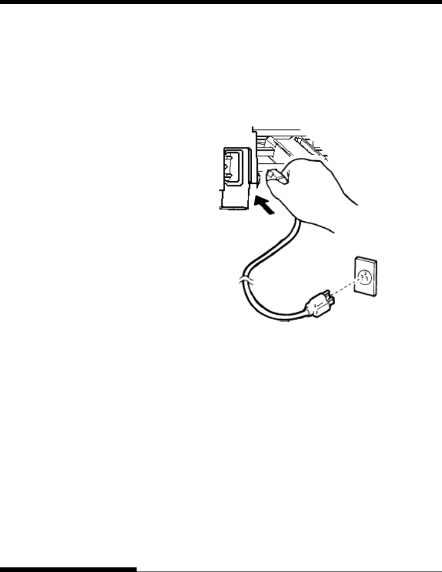
CONNECTING THE POWER
CORD
SETTING UP
2-12 User's Manual
Connecting the power cord
3. Make sure that the power cord is securely connected.
4. Turn on the power by pressing the side marked “1” on the power
switch. Within a few seconds, the POWER indicator on the printer
control panel will light, the print head will move to its home position,
and the ONLINE indicator will light (green).
NOTE
If no forms are loaded, the printer may beep and the red PAPER OUT
indicator may light and the ONLINE indicator will not light if the paper
select lever is set backward to the continuous forms position. Move the
paper select lever forward to the single sheet position (as described in the
next section). The PAPER OUT indicator will go out. This condition is a
result of the factory default settings and poses no problem.
To plug in the power cord:
1. Plug one end of the power cord into the power connector on the
rear of the printer.
2. Plug the other end of the power cord into the power outlet.
SETTING UP
User's Manual 2-13
Quick
Reference Introduction Setting Up Paper
Handling Printing Setup Mode
TESTING THE PRINTER
(OFFLINE)
At this point, load paper and run the printer self-test. The self-test checks
printer performance and print quality before you connect the printer to the
computer. Use either single sheets or continuous forms (see Chapter 3). This
section describes the self-test procedure using single sheets.
Loading Paper for the Self-Test
To print the self-test, use paper wider than 215.9 mm (8.5 inches) and set the
left paper guide all the way to the right to avoid clipping the test pattern.
Standard letter or A4 size paper can be used lengthwise (portrait mode).
Before loading paper, make sure that the printer is on. Then, proceed as
follows:
1. Make sure that the paper thickness lever (located on the top right of
the printer) is at position 1. Make sure that the paper select lever
(located on the top left of the printer) is set to the front, as shown
below.
Loading a sheet of paper

SETTING UP
2-14 User's Manual
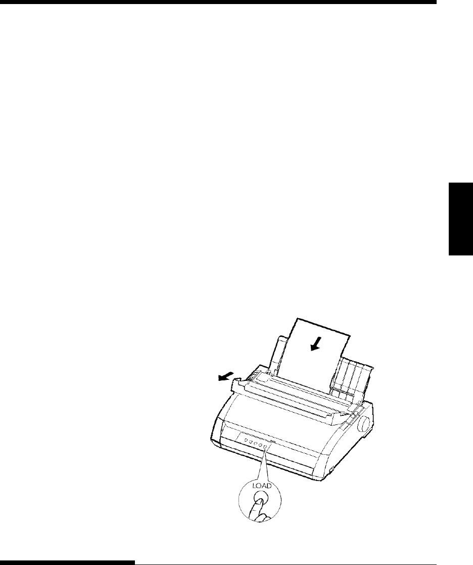
2. Raise the cut sheet stand. Move the left paper guide all the way to the
right. Insert the sheet of paper into the cut sheet stand. Letter or A4
size paper, inserted lengthwise (portrait mode) with this setting, will
not result in clipping.
Adjust the right paper guide so that the paper lies flat on the cut sheet
stand.
3. Slide the paper along the cut sheet stand until its bottom edge touches
the platen. Then press the LOAD button. The paper will advance to
the top-of-form position.
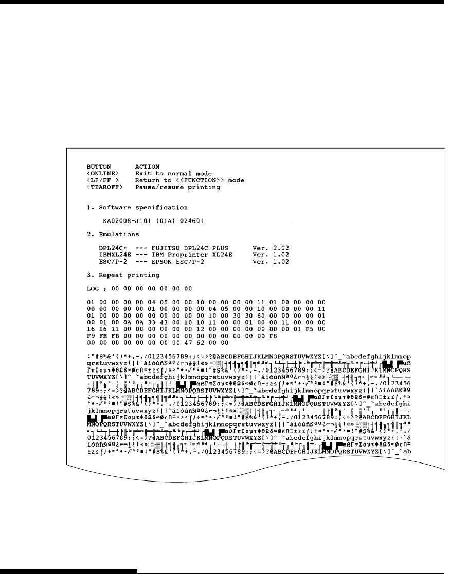
Printing the Self-Test
The printer has a built-in self-test program. The self-test prints the firmware
version, the names of the printer’s resident emulations, and all of the charac-
ters available in the emulations. The self-test prints 80 characters per line.
To print a self-test page, make sure that a sheet of paper is loaded. Then
proceed as follows:
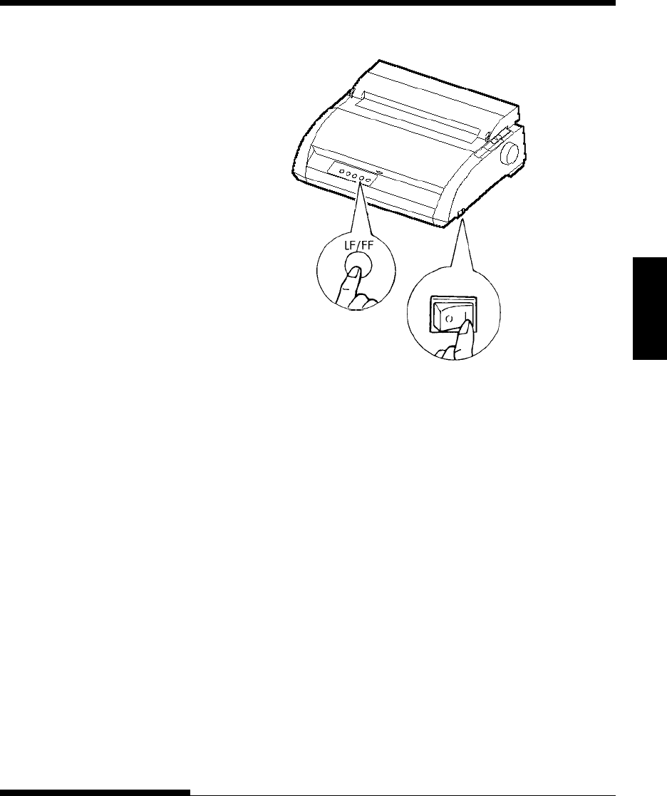
1. Turn the printer off.
2. While pressing the LF/FF button, turn the printer back on. Keep the
LF/FF button pressed until the printer beeps. Self-test printing will
start.
SETTING UP
User's Manual 2-15
Quick
Reference Introduction Setting Up Paper
Handling Printing Setup Mode
Starting the self-test
3. Allow printing to continue for a dozen or more lines of repeat
printing. To stop printing, press the TEAR OFF button. Manually
turn the platen knob clockwise to remove the test page.
NOTE
Do not try to use the LF/FF (line feed/form feed) button to eject the
paper. In self-test mode, LF/FF cannot be used to feed paper forward.
4. Examine the self-test page. It should look like the sample on the next
page.
Check that printing is uniform and that there are no light, dark, or
smudged areas. If the print quality is good, go to step 5. Otherwise,
try to correct the problem as follows:
• Make sure that the ribbon is installed correctly.
• Make sure that the paper thickness lever is set to position 1.
SETTING UP
2-16 User's Manual
• Insert a new sheet of paper into the cut sheet stand. Turn the platen
knob to manually advance the paper until the top edge has moved
past the paper bail rollers.
• Press the TEAR OFF button to restart printing. If the print quality
remains poor, turn off the printer and contact your dealer for
assistance.
Sample self-test page
5. To exit the self-test mode, press the ONLINE button. The printer will
return online.

SETTING UP
User's Manual 2-17
Quick
Reference Introduction Setting Up Paper
Handling Printing Setup Mode
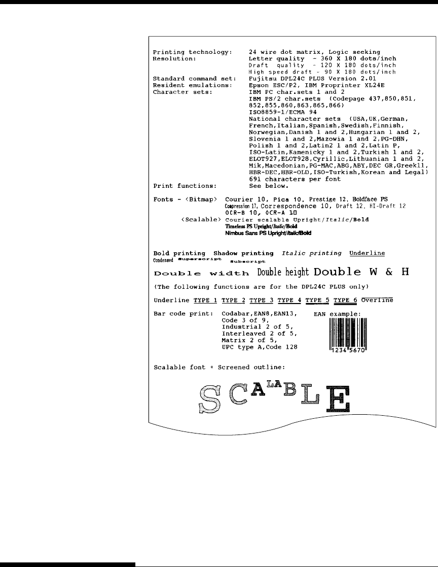
NOTE
The printer can also print a special “demo pattern” that illustrates some of
the printer’s capabilities. To print the demo pattern:
1. Load a sheet of letter or A4 size paper.
2. Turn the printer off .
3. While pressing TEAR OFF button, turn the printer back on. The
printer will start printing the demo pattern.
4. The demo pattern stops printing after one page. To pause or restart
the demo during printing of a page, press the ONLINE button.
5. To exit demo mode, turn the printer off.
SETTING UP
2-18 User's Manual
Demo pattern

SETTING UP
User's Manual 2-19
Quick
Reference Introduction Setting Up Paper
Handling Printing Setup Mode
CONNECTING THE PRINTER
TO YOUR COMPUTER
Your printer supports one of the following interface options:
• Centronics parallel interface only
• Centronics parallel interface+RS-232C serial interface
• Centronics parallel interface+USB (+LAN) interface
The RS-232 serial interface is a factory-installed option for a Centronics
parallel interface model. Installation of the serial option provides a dual
interface feature enabling the connection of either interface but inhibiting the
operation of both interfaces at the same time.
The parallel interface connector has wire clips. The serial interface connector
has tapped holes. Cables for these interfaces are available from dealers, cable
manufacturers, and other suppliers.
The LAN card is a user installable option. For details, see Chapter 8 or refer to
the Online Manual that comes with the LAN card.
For detailed interface specifications, see Appendix D.
Selecting a Parallel Interface Cable
For the parallel interface, use a cable that meets the following specifications:
√At the printer end, use a shielded male Centronics connector, such as
an Amphenol DDK 57FE-30360 or its equivalent. To prevent RFI
(radio frequency interference), the connector cover must be connected
to the cable shield.
√At the computer end, most computers (including IBM PCs) require a
male DB-25P connector. Some computers, however, require a
Centronics connector. To determine the type of connector your
computer uses, refer to your computer user manual.
√Make sure that the cable length does not exceed 3 meters (10 feet).
Selecting a Serial Interface Cable
For the serial interface, use a cable that meets the following specifications:
√At the printer end, use a 25-pin male connector, such as a Cannon DB-
25P or its equivalent.
√To determine the type of connector your computer requires, refer to
your computer user manual or ask your dealer.
√The cable length can be up to 15 meters (50 feet). This type of length
is required in many networking and shared-printer configurations.
SETTING UP
2-20 User's Manual
Shutter
Connecting the Interface Cable
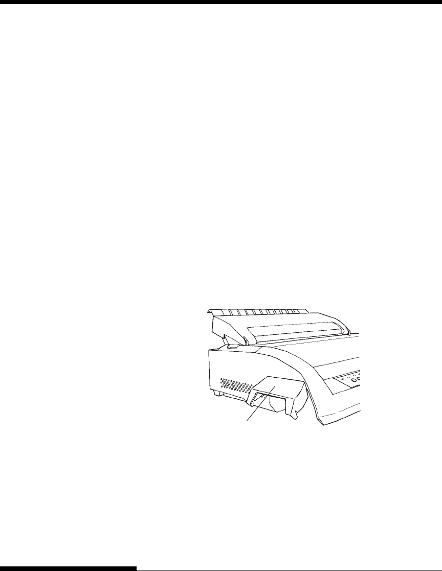
To connect the interface cable:
1. Turn off both the printer and the computer.
2. Pull the shutter on the left side of the printer upward as far as it will go.
Opening the shutter
NOTE
Removing and Attaching the Shutter
When use of the shutter is not required, remove it by using the following
procedure.
Selecting a USB Cable
√
When the USB interface is used to connect to the host computer, the
parallel interface and the serial interface (factory add-on option) cannot
be connected simultaneously.
√ The USB interface does not guarantee all connections of USB-
supported devices.
Selecting a LAN cable
√
When the LAN cable is connected, the parallel and USB cables cannot
be used.
√
The LAN cable, when used in 100BASE-TX environments, must
conform to category 5 or higher.
SETTING UP
User's Manual 2-21
Quick
Reference Introduction Setting Up Paper
Handling Printing Setup Mode
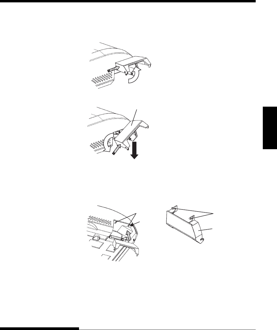
Removing the shutter
1. Open the shutter.
2. Gently push the back end of the shutter
toward the front of the printer.
3. While holding the shutter in the position
described in step 2, rotate it in the manner
shown in the figure on the left to
disengage it.
4. Remove the shutter.
1
2
2
3
4
Shutter
Attaching the shutter
(a)
5
Mounting slots Tab s
Shutter
5. Tilt the shutter and pass the shutter tabs
through the mounting slots, starting with
the slot on side (a) shown in the figure on
the left. The order in which the shutter tabs
are passed through the slots is the reverse
of that for removing the shutter.
CAUTION
Take care not to use excessive force when pushing the back of the shutter
toward the front of the printer. Otherwise, the shutter tabs may be
damaged.
SETTING UP
2-22 User's Manual
NOTE
The LAN interface is a user add-on option.
When installing a LAN card, remove the two screws securing the cover
and remove the cover. Then insert the LAN card and reattach the cover
with the two screws removed earlier. For details, refer to the Online
Manual that comes with the LAN card.
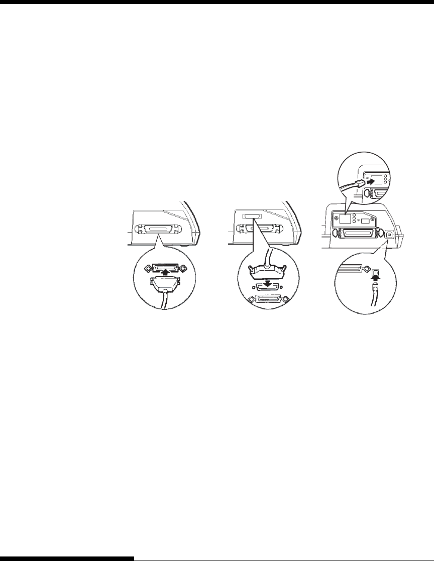
4. To secure a parallel interface cable, flip the fastener clips located on
the printer into the notches on the cable connector. To secure a serial
interface cable, tighten the screws in the cable connector.
5. Attach the other end of the interface cable to your computer.
Gently pull on the cable to verify that it is secure.
6. Close the shutter.
Centronics parallel Centronics parallel + USB (+LAN)Centronics parallel + RS-232C
Connecting the interface cable
3. Attach the interface cable to the connector.
Do not connect more than
one interface cable type to the printer at the same time.
To reattach the shutter, tilt the shutter and insert one of its convex parts
into the installation hole of the printer, and then insert the other part in
the other hole. After inserting both convex parts, lower and push the
shutter in to its original position.

SETTING UP
User's Manual 2-23
Quick
Reference Introduction Setting Up Paper
Handling Printing Setup Mode
Before printing with your software, verify that the correct emulation is
selected on your printer. This section describes the available emulations and
their selection.
For Experienced Users:
The printer’s preselected factory setting is the Fujitsu DPL24C PLUS
emulation. If this emulation is acceptable, you may skip this section.
An emulation is a set of commands used by your software to communicate
with the printer. There are many different emulations available for printers.
Each emulation has unique features and capabilities. This printer offers three
resident emulations:
• Fujitsu DPL24C PLUS (for Fujitsu DL-series printers)
• IBM Proprinter XL24E
• Epson ESC/P2
Resident emulations are stored in the printer’s permanent memory.
Here are some points to help you determine which emulation to select:
√Determine which emulations your software supports. (Refer to your
software documentation.) Since most software programs support this
printer, try to run a program with the factory default emulation first.
(DPL24C PLUS emulation is the factory default.) Try this emulation
even if you are not sure of which emulation to choose. See Chapter 5
for detailed information about how your printer communicates with
your software.
√If you are using more than one software package, determine which
emulation is supported by the software you use most frequently.
Select that emulation.
√If your software supports more than one emulation, select the
DPL24C PLUS emulation if possible. This emulation has the greatest
capabilities.
√If you want to use an emulation that is not supported by your software,
contact your software manufacturer or printer dealer and ask whether
support is available. You may be able to obtain a printer driver that is
not shipped with the original software package.
SELECTING AN EMULATION
SETTING UP
2-24 User's Manual
To select an emulation, proceed as follows:
1. Turn the printer on and load a sheet of paper.
To change a single printer setting, such as the emulation, you can use
a single sheet paper. To change several printer settings as described in
Chapter 5, you must load continuous forms paper. See Chapter 3 for
paper loading instructions.
2. Enter setup mode.
Press the ONLINE button to place the printer offline. Then, press the
TEAR OFF button and the ONLINE button.
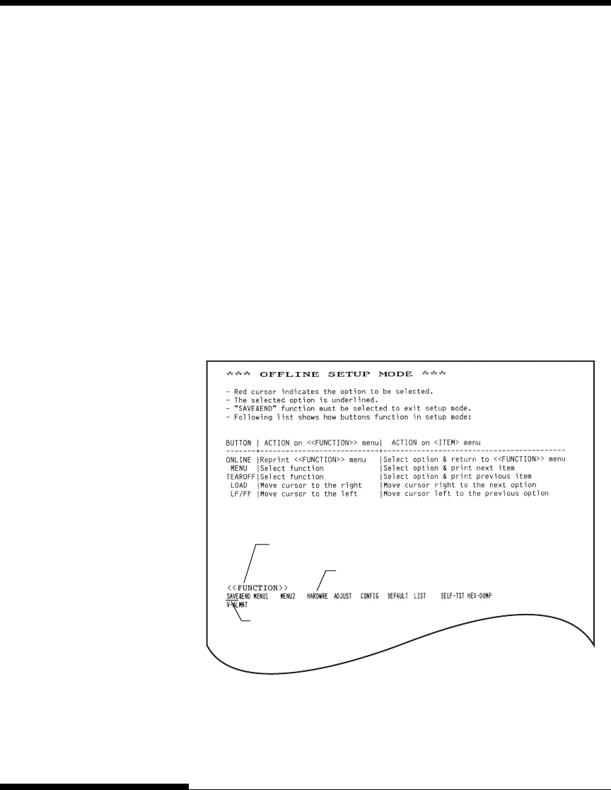
As the printer enters offline setup mode, it prints the following
information:
Initial printout in setup mode
Check that the <<FUNCTION>> menu is printed at the bottom of the
page.
<<FUNCTION>>
menu Function
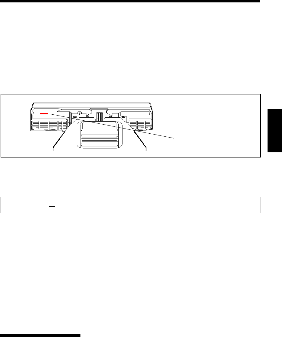
Red cursor on print guide
SETTING UP
User's Manual 2-25
Quick
Reference Introduction Setting Up Paper
Handling Printing Setup Mode
3. Select the MENU1 function.
Locate the red cursor on the plastic print guide. Initially, this cursor
should be positioned under SAVE & END at the beginning of the
<<FUNCTION>> menu. Press the LOAD button repeatedly to
position the red cursor beneath MENU1, as shown below:
Press the MENU button to select MENU1 and print the following
<EMULATE> options:
<<FUNCTION>>
SAVE&END MENU1 MENU2 H ADJUST CONFIG DEFAULT LIST SELF-TST HEX-DUMP
V-ALMNT
<EMULATE> DPL24C+ XL24E ESC/P2
The currently selected emulation is indicated by a short underline. In
the figure shown above, the Fujitsu DPL24C PLUS emulation is
selected.
4. Select an emulation.
Press the LOAD button repeatedly to position the red cursor under the
required emulation. Press the MENU button to select the emulation
and print the next MENU1 item.
Press the LOAD button to position
to the red cursor.

SETTING UP
2-26 User's Manual
5. Exit MENU1.
Press the ONLINE button to exit the MENU1 function and reprint the
<<FUNCTION>> menu.
6. Exit setup mode to save the emulation.
To exit setup mode and save the new emulation, make sure that the red
cursor is positioned under SAVE & END. Then press the MENU
button. The printer selects SAVE & END and then goes online.
To change other printer settings using the printer setup mode, see Chapter 5.
Once the self-test verifies that the printer is functioning correctly, try printing
using one of your software packages. This exercise will ensure that the printer
is correctly connected to your computer.
If you are using a parallel interface, the printer usually prints the correct
characters automatically. However, you may need to adjust the page layout or
various print features using your software or the printer setup mode. If you are
using a serial interface, the printer may not work at all or it may print a lot of
“?” characters. In this case, the serial settings on the printer do not match
those of your computer or your software. Before changing any settings, use
the procedure described below to try printing using the printer’s preselected
factory settings.
Test communication between the printer and computer as follows:
1. Load a sheet of paper.
2. Check that the printer is online. If the ONLINE indicator is not green,
press the ONLINE button.
3. Try to print using your word processor, a programming language, or
other software.
PRINTING A SAMPLE PAGE
(ONLINE)

SETTING UP
User's Manual 2-27
Quick
Reference Introduction Setting Up Paper
Handling Printing Setup Mode
4. Use your software printer selection menus or the printer setup mode
(described in Chapter 5) to make required changes in the page layout
or other print features.
If the printer does not print or prints the wrong characters, proceed as
follows:
• Make sure that the interface cable is properly connected.
• Make sure that the printer emulation selected in your software is
the same as that selected on the printer.
• If you are using a serial interface, make sure that the printer
serial interface settings are the same as those on the computer. The
printer’s preselected factory settings are 8 data bits, no parity, 1
stop bit, 9600 baud, and XON/XOFF protocol.
You can change the serial settings on either the printer or your
computer. To change the printer settings, see Chapter 5. To
change the computer settings, use the selection menus provided by
your software or the commands of your computer operating system.
The following example uses the MS-DOS operating system:

SETTING UP
2-28 User's Manual
Using MS-DOS to Specify Serial Interface Settings
For an IBM PC or compatible device, use the following MS-DOS
MODE commands to set the computer serial settings to match the
printer factory settings:
MODE COM1:9600,N,8,1,P
MODE LPT1:=COM1
To activate these settings whenever you turn the computer on, write
the MODE commands in your AUTOEXEC.BAT file. Make sure
that the MODE.COM file is included in your root directory.
If the printer still doesn’t work, consult your dealer or someone
experienced in serial interface communications.
• If an error occurs during printing with Windows, simply printing
the page again will cause the printed characters to be garbled. To
avoid this problem, execute reset from the control panel or turn off
the printer, then print the page again.
You are now finished setting up and testing the printer. To familiarize
yourself with everyday printer operations, such as loading paper, selecting
print features, and printing, see Chapters 3 and 4.

SETTING UP
User's Manual 2-29
Quick
Reference Introduction Setting Up Paper
Handling Printing Setup Mode
A printer driver is required for using the printer in a Windows environment.
Special printer drivers for Windows 95, 98, Me, NT 4.0, XP, and 2003 are
provided with the DL3750+/3850+ printer.
For information about how to install printer drivers, refer to Readme.txt of the
printer driver to be installed.
· These printer drivers run with DLP24C+ emulation. Be sure to specify
DLP24C+ emulation for the printer mode.
· The DL3750+/3850+ printer driver is a printer driver for monochrome
printing.
The color data printing result may differ from its print preview or the
monochrome data printing result.
INSTALLING THE
PRINTER DRIVER

SETTING UP
2-30 User's Manual
User's Manual
PAPER HANDLING
3-1
Quick
Reference Introduc-
tion
Setting Up Paper
Handling Printing Setup Mode
PAPER HANDLING
This chapter explains how your printer uses paper.
Topics covered are:
• Selecting paper
• Overview of paper operations
• Adjusting for paper thickness
• Using single sheets
• Using continuous forms
• Feeding and positioning paper
• Switching paper types
Tips for paper handling are given at the end of this chapter. Check that
section if you are using multipart forms, envelopes, or labels.
The printer can handle either single sheets or continuous forms. Single sheets,
also called cut sheets, include envelopes and noncontinuous, multipart forms.
Continuous forms include labels and multipart forms fed into the printer using
the forms tractors.
For best results, use paper that meets the specifications listed below. (See
Appendix B for detailed specifications.) If you are unsure of the suitability of
a particular paper, try testing the paper or consult your dealer.
Length 80 Single sheets: 76 to 364 mm (3 to 14.3 in)
column Continuous forms: 102 mm (4 in) or greater
136 Single sheets: 76 to 420 mm (3 to 16.5 in)
column Continuous forms: 102 mm (4 in) or greater
Width 80 Single sheets: 102 to 267 mm (4 to 10.5 in)
column Continuous forms: 102 to 267 mm (4 to 10.5 in)
136 Single sheets: 102 to 420 mm (4 to 16.5 in)
column Continuous forms: 102 to 420 mm (4 to 16.5 in)
Thickness 0.35 mm (0.014 in) maximum total thickness.
Copies 1 to 5 copies, including the original.
For carbon-interleaved paper, the carbon counts as a
copy.
3
SELECTING PAPER
PAPER HANDLING
User's Manual3-2
OVERVIEW OF PAPER
OPERATIONS
The following levers and buttons are used in paper handling:
• Paper select lever at the top left corner of the printer
• Paper thickness lever at the top right corner of the printer
• LF/FF, TEAR OFF, LOAD, and MENU buttons on the control panel
(A different function is enabled when each button is pressed in
conjunction with the ONLINE button.)
The following figure shows the location of each lever and button:
Printer levers and buttons
Table 3.1 summarizes the use of levers and buttons in paper handling. More
detailed information is provided later in this chapter.
NOTE
To load or feed paper, the printer must be:
• Online but not receiving or printing data
• Offline but not in setup mode
To micro-feed paper, which is done with the ONLINE button, the printer
must be:
• Offline but not in setup mode.
Paper
thickness
lever
Control panel
Paper select
lever
Menu indicators
Buttons
User's Manual
PAPER HANDLING
3-3
Quick
Reference Introduc-
tion
Setting Up Paper
Handling Printing Setup Mode
Lever/Button Purpose Action
LF/FF Form feed Press and hold LF/FF to execute a form
feed. Continuous forms are fed forward
by one page. Single sheets are ejected.
Line feed Press LF/FF within three seconds to feed
paper forward by one line.
Forward micro Press LF/FF and ONLINE to feed paper
feed forward by 1/180 inch.
TEAR OFF Advance forms Press TEAR OFF to advance the forms
for tear-off perforation to the tear-off edge. Tear off
the forms, then press any button to
retract the remaining forms.
LOAD Load/unload Press LOAD to load paper or to retract
continuous forms to the "park position".
Reverse micro Press LOAD and ONLINE to feed
feed paper backward by 1/180 inch.
MENU Save adjusted Press MEMU and ONLINE to perma-
load point nently store the load position adjusted by
micro feeding
Paper Select paper Move the paper select lever forward for
select path single sheets (cut sheet stand).
lever * Move the paper select lever backward for
continuous forms.
Paper Adjust for Select the number corresponding to the
thickness paper thickness number of copies (including the original).
lever or number of Vary the setting up or down (including A
copies to D) to optimize printing. Select D when
replacing ribbon or clearing a paper jam.
* The following graphics are engraved on the cover.
:Continuous forms
:Cut sheets
Table 3.1 Levers and Buttons Used for Paper Handling
PAPER HANDLING
User's Manual3-4
ADJUSTING FOR PAPER
THICKNESS
The printer can handle paper of different thicknesses, including multipart
forms with up to five parts (original plus four copies). For details on paper
thickness specifications, see Appendix B.
The paper thickness lever, located at the top right corner of the printer, allows
you to adjust for different paper thicknesses. Be sure to adjust the paper
thickness lever whenever you change the number of copies being printed.
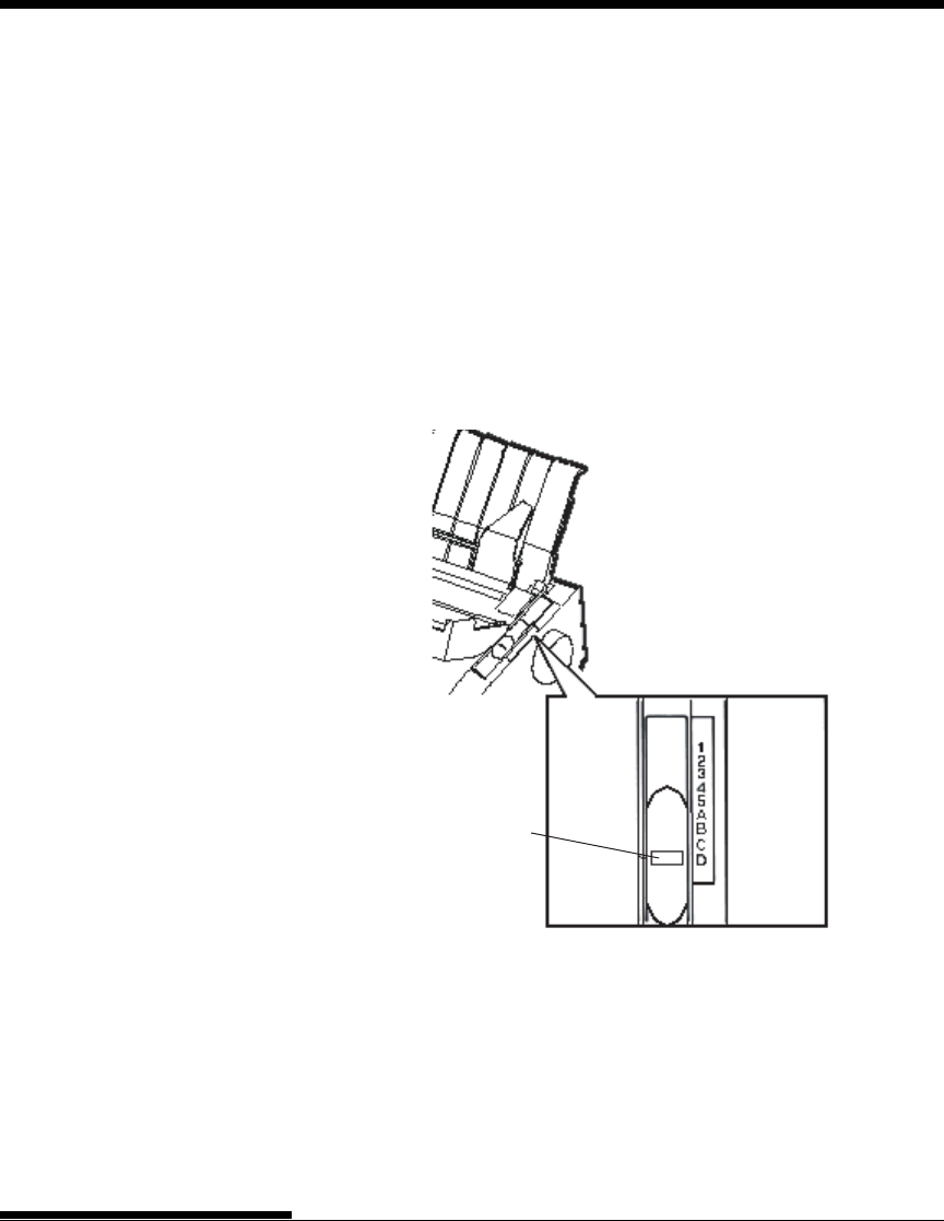
The paper thickness lever has nine settings: 1 to 5 and A to D. Use Table 3.2
to determine the appropriate setting for your paper; then, move the paper
thickness lever to the appropriate position.
Adjusting the paper thickness lever
Paper thickness lever
Move to D.
User's Manual
PAPER HANDLING
3-5
Quick
Reference Introduc-
tion
Setting Up Paper
Handling Printing Setup Mode
USING SINGLE SHEETS This section describes how to load paper in the cut sheet stand.
The cut sheet stand allows paper to be loaded manually, one sheet at a time.
Loading a Single Sheet of Paper
To load a sheet of paper into the cut sheet stand:
1. Make sure that the printer is turned on. Check that rear-fed continu-
ous forms are retracted to the park position. (For details, see the
section Unloading Continuous Forms later in this chapter.)
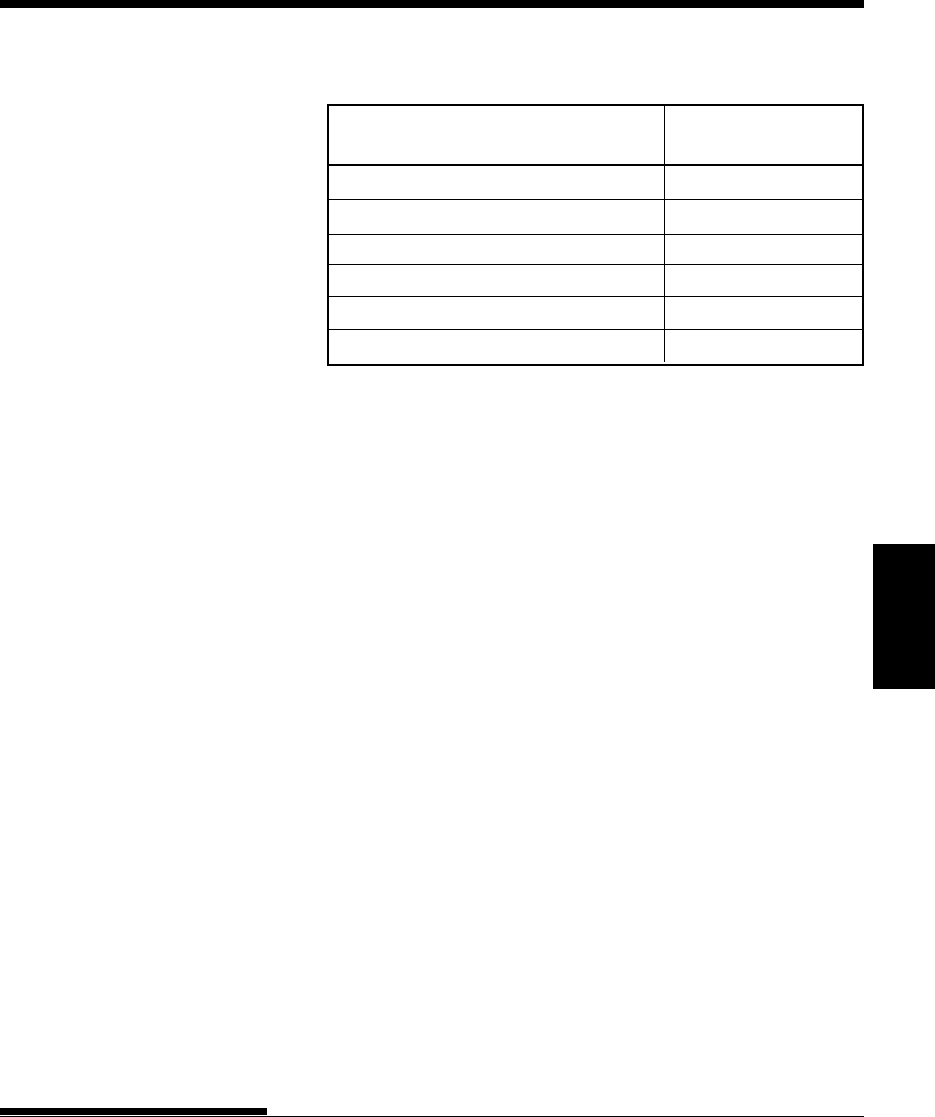
Table 3.2 Paper Thickness Lever Settings
Number of Copies
(Including the Original) *1
1 copy 1
2 copies 2
3 copies 3
4 copies 4
5 copies 5
Ribbon replacement D
*1 For carbon-interleaved paper, the carbon counts as one copy.
*2 Vary the setting up or down (including A to D) to optimize printing.
Select D when replacing a ribbon or clearing a paper jam. For labels
and envelopes, use trial-and-error to determine a satisfactory setting.
NOTE
If printing is messy, the ribbon misfeeds, or the paper jams, move the
lever one setting higher.
Setting *2
PAPER HANDLING
User's Manual3-6
Preparing to load a sheet of paper
5. Insert a sheet of paper into the cut sheet stand. Make sure that the
bottom edge of the paper engages snugly with the platen. Adjust the
right paper guide.
Left margin
(minimum)
2. If necessary, reset the paper thickness lever. (See the section
Adjusting for Paper Thickness earlier in this chapter.)
3. Move the paper select lever forward. (This lever is at the top left of
the printer.)
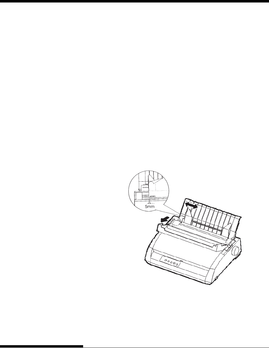
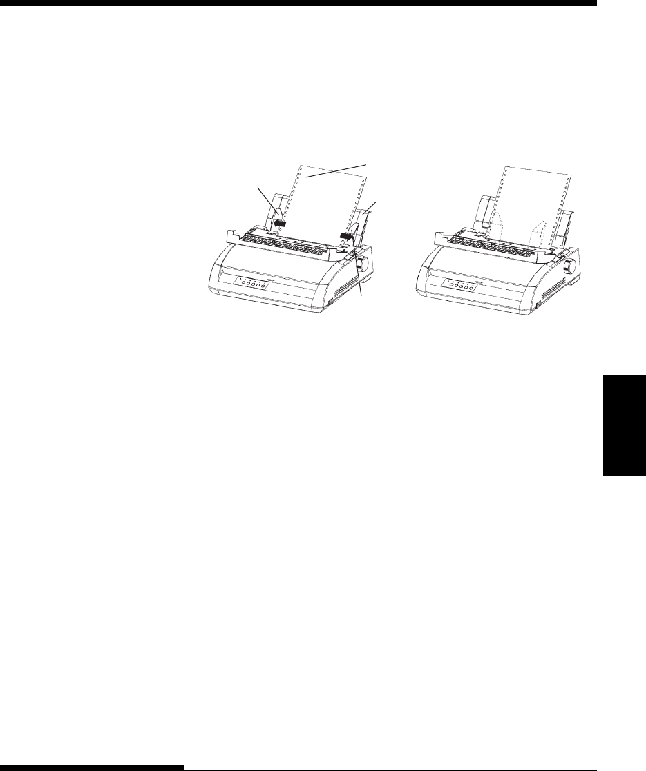
4. Raise the cut sheet stand. Position the left paper guide. Note that its
movable range is limited.
Adjusting the left margin
Below the left paper guide, the cut sheet stand has a scale graduated in units of
0.1 inch. When the left paper guide is positioned all the way to the right, the
left margin is approximately 5 mm (0.2 inch). To help align paper, also use
the two inch-based rulers on the ejection cover of the printer. The gradations
on the ruler are for 10 columns per inch.
User's Manual
PAPER HANDLING
3-7
Quick
Reference Introduc-
tion
Setting Up Paper
Handling Printing Setup Mode
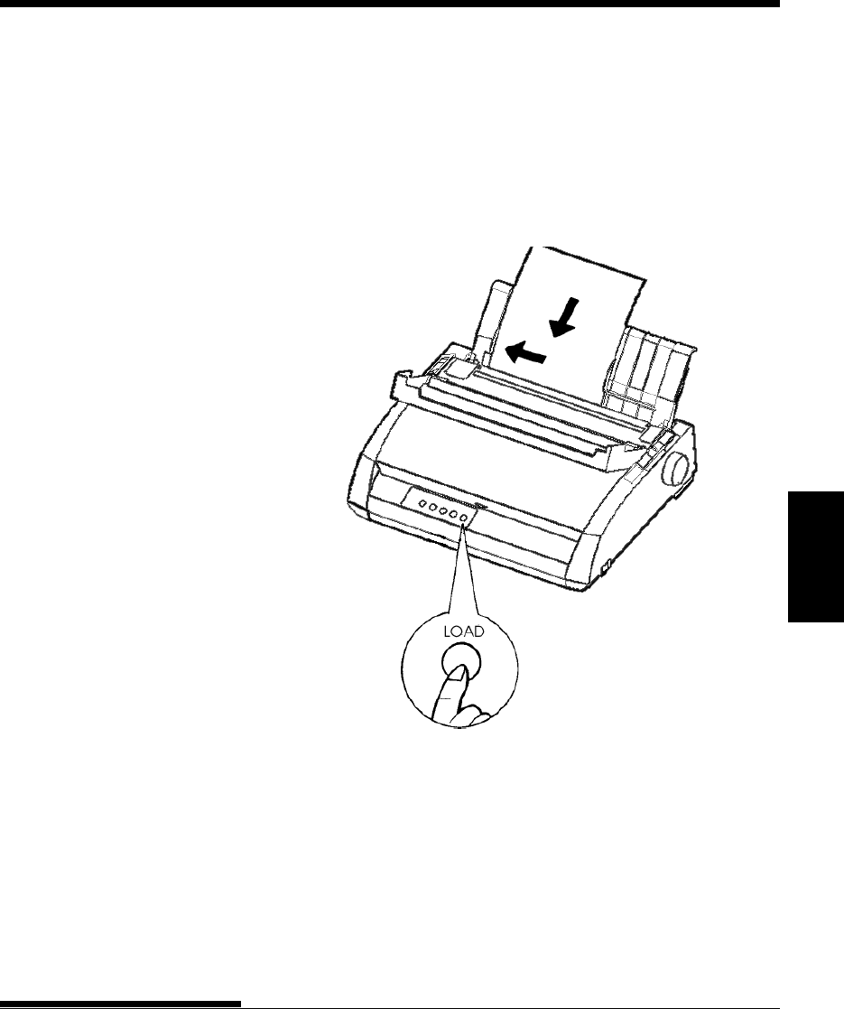
Loading a sheet of paper
7. Place the printer online. Print a sample page and check the page
margins. Make the following adjustments, as necessary:
• Horizontal alignment. Readjust the paper guides if required.
• Top-of-form setting (see Chapter 5).
• Margin settings. Use your software or the printer setup mode (see
Chapter 5).
6. Press the LOAD button. The paper will advance to the top-of-form
position. The top-of-form position is the first line on which printing
can start. To adjust the position of the paper slightly, simultaneously
press the ONLINE button and the LF/FF button or the LOAD button.
The paper will move forward or backward in 1/180-inch increments.

PAPER HANDLING
User's Manual3-8
USING CONTINUOUS
FORMS
Ejecting Single Sheets
If you print using software, each sheet is ejected automatically when the end of
the printed page is reached. To manually eject sheets of paper, use either of
the following methods:
• Press and hold down the LF/FF button to execute a forward form
feed.
• Turn the platen knob clockwise.
Continuous forms paper, fanfolded at the horizontal perforations, is ideal for
printing rough drafts and long files. The paper is fed into the printer using the
forms tractors. The forms tractors unit at the rear of the printer pushes paper
from the rear to the platen. This is called push-tractor feeding.

User's Manual
PAPER HANDLING
3-9
Quick
Reference Introduc-
tion
Setting Up Paper
Handling Printing Setup Mode
Positioning the Paper Stack
Place the stack of continuous forms paper directly below the rear of the
printer. After the paper is installed in the printer, the paper path should look
like this:
Good placement
Placement of continuous forms
Feed from rear slot
Bad placement
PAPER HANDLING
User's Manual3-10
Loading Continuous Forms
This section explains how to use continuous forms. The tractor unit pushes
continuous forms.
To load continuous forms paper:
1. Make sure that the printer is turned on. Remove any single- sheet
paper from the printer.
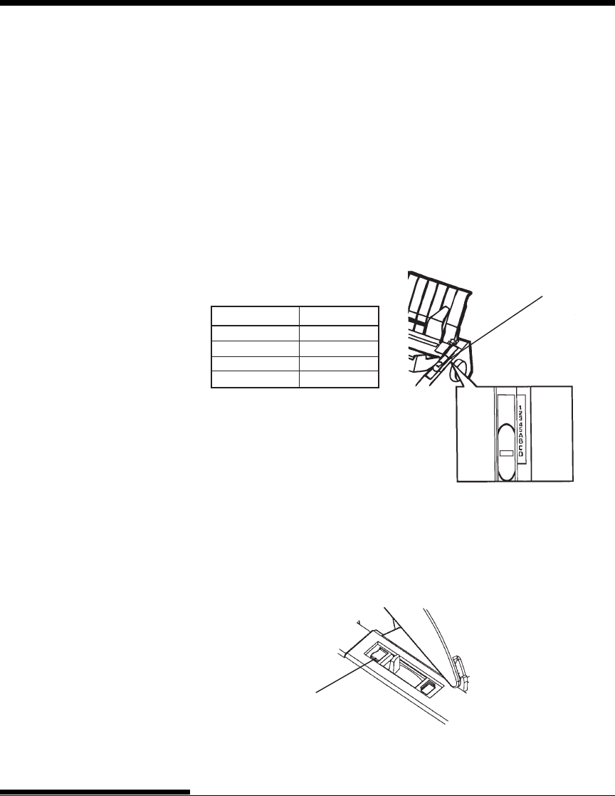
2. If necessary, readjust the paper thickness lever for continuous forms.
(See the section Adjusting for Paper Thickness earlier in this
chapter.)
Continuous forms side
Preparing to load continuous forms paper
Paper thickness lever
No. of Copies Setting
1 1 to 2
2 to 3 2 to 3
4 3 to 4
5 4 to 5
Paper thickness lever setting
3. Move the paper select lever to the rear of the printer.
User's Manual
PAPER HANDLING
3-11
Quick
Reference Introduc-
tion
Setting Up Paper
Handling Printing Setup Mode
4. Release the tractor locking levers by pulling them up. Open the tractor
paper holders. See the following figure.
5. Position the right tractor (as seen from the rear of the printer). Push
the right locking lever down to secure the tractor. Center the middle
forms support.
Cut sheet stand
Locking levers Paper select lever
Continuous
forms side
Forms
tractors
Positioning the tractors
Adjusting the left margin
Below the right tractor, as seen from the back, there is a tractor guide, short
inch-based ruler graduated in 10 columns per inch. Use the ruler to help
position the tractor. When the paper edge is positioned to the left most line,
the left margin is approximately 12mm (0.5 inch) including perforation area.
Tractor guide
Tractor paper holders
Tractor paper holders
Ajusting the left margin
PAPER HANDLING
User's Manual3-12
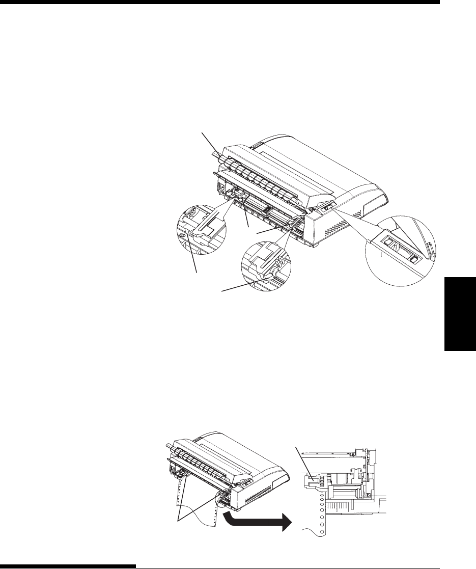
6. Fit the paper feed holes onto the left and right tractor pins. Adjust the
left tractor (as seen from the rear of the printer) to the width of the
form. Close the paper holders.
7. Pull the left tractor (as seen from the rear) to stretch the paper taut.
Push the left locking lever down to secure the tractor in place.
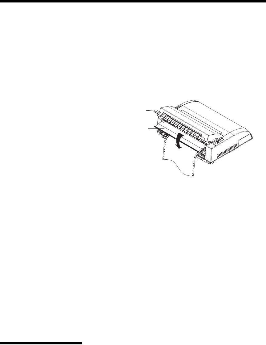
8. Strongly pull the back cover off of the cut sheet stand (in the
direction indicated by the arrow) and set it down.
Cut sheet stand
Back cover
Setting the back cover
9. Install the cut sheet stand. For installation, see the section Installing
the Cut Sheet Stand in Chapter 2.
10. Press the LOAD button to advance the paper to the top-of-form
position. Top-of-form is the first line on which printing can start.
11. Press the ONLINE button to place the printer online. Print a sample
page and check the page margins. Make the following adjustments,
as necessary:
• Horizontal alignment. Move the forms tractors as required.
• Top-of-form setting (see Chapter 5).
• Margin settings. Use your software or the printer setup mode (see
Chapter 5).
If the paper cut position and the perforation position do not fit, adjust
them by using the following procedure.
User's Manual
PAPER HANDLING
3-13
Quick
Reference Introduc-
tion
Setting Up Paper
Handling Printing Setup Mode
NOTE
When you use continuous forms, make sure that the edges of both left and
right paper guides do not touch the paper.
Slide both paper guides flush against the ends of both sides.
Adjusting the TEAR OFF position
When the TEAR OFF button is used to advance the paper to cut it, the paper
cut position and the perforation position may not match. In such cases, adjust
their positions by using the following procedure.
Adjustment procedure :
1. Use the TEAR OFF button to advance the paper to its cut position.
(Keep holding down the TEAR OFF button.)
2. While holding down the TEAR OFF button, adjust the cut position by
using the LF/FF button or LOAD button.
- LF/FF button: Pressing this button once extends the paper feed
amount by 1/180 inches.
- LOAD button: Pressing this button once reduces the paper feed
amount by 1/180 inches.
- The adjustment range is plus or minus 63/180 inches
(approximately 9 mm). When it is exceeded, an alarm beeps.
3. When the cut position is adjusted, release the TEAR OFF button.
The paper feed amount at the end of the adjustment is stored as the
amount by which the paper will be fed when the TEAR OFF button is
pressed.
Good Unacceptable
Right paper
guide
Left paper
guide
Continuous
form
Cut sheet
stand
PAPER HANDLING
User's Manual3-14
Unloading Continuous Forms
To unload continuous forms:
1. Make sure that the paper select lever is set to the rear position.
2. Press the LOAD button. The continuous forms paper is retracted to
the park position. If the paper cannot be retracted in one operation,
continue to press the LOAD button until the paper is parked.
NOTE
The printer can retract continuous forms paper a maximum of
55.8 cm (22 inches) per operation.
3. To remove the paper, raise the tractor paper holders and lift out the
paper.
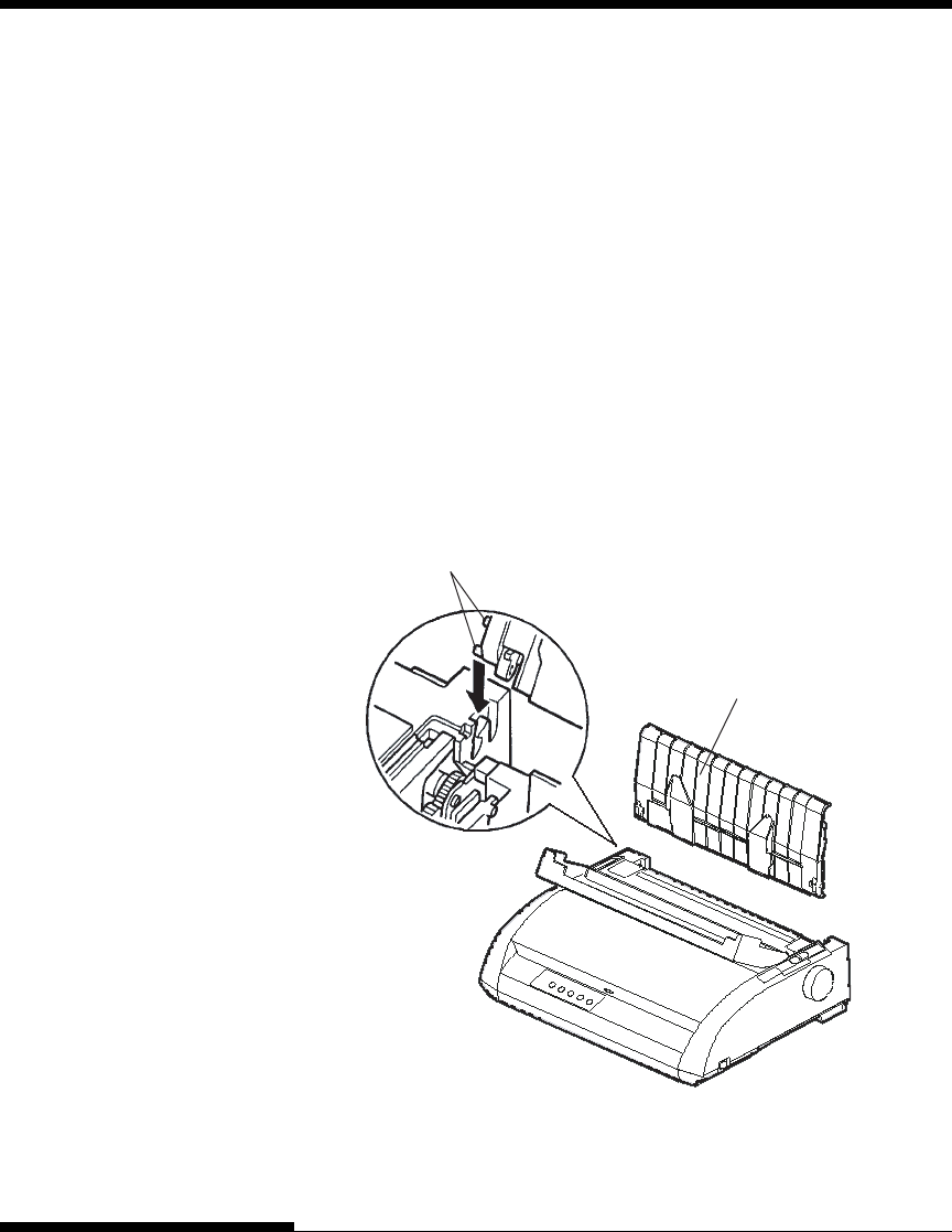
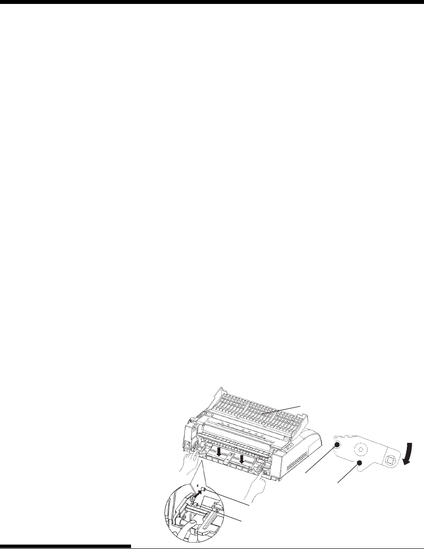
Installing the Tractor Unit
Install the tractor unit by following the procedure below if it happens to be
disengaged from the studs.
1. Turn off the printer.
2. Remove the cut sheet stand and open the acoustic cover.
3. Hook the notch of the tractor unit against stud 1, and then rotate the
unit downward so as to set the other notch onto stud 2.
Stud 1
Stud 2
Stud 1
Stud 2
Acoustic cover
User's Manual
PAPER HANDLING
3-15
Quick
Reference Introduc-
tion
Setting Up Paper
Handling Printing Setup Mode
Tearing off continuous forms
3. Press any button to retract the forms back to the top-of-form position.
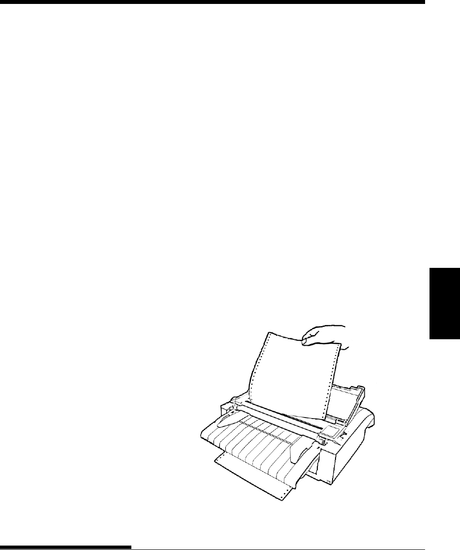
Tearing Off Continuous Forms
Your printer has a special “tear-off edge” that allows you to tear off printed
pages without wasting paper. The tear-off edge is located on the ejection
cover.
To tear off continuous forms using the tear-off edge:
1. Press the TEAR OFF button. The bottom perforation of the last page
advances to the tear-off edge. If you specified TEAR OFF: AUTO
using the CONFIG function in setup mode, the paper automatically
advances to the tear-off edge at the end of each job (or when the
printer has printed all the data received).
NOTE
If the bottom perforation of your paper is not positioned at the
tear-off edge, the length of your paper may not be specified
correctly in your software or the printer setup mode. Check that
the paper length is specified correctly. For information on
specifying page length using setup mode, see Chapter 5.
2. Tear the paper off at the perforation.

PAPER HANDLING
User's Manual3-16
Line Feed/Form Feed
Use the line feed/form feed function to move paper forward. This function is
valid when the printer is online or offline. Pressing and holding down the LF/
FF button feeds one sheet of paper. Pressing the LF/FF button once advances
the paper one line (do not hold the button more than three seconds).
The printer does not allow you to execute “reverse” form or line feeds from
the control panel. To feed paper backward, manually rotate the platen knob.
Remember that the top-of-form will slip from the original setting.
Micro Feed
Use the micro feed function to fine tune the position of the paper. This
function is valid when the printer is offline. Press the ONLINE and LF/FF
buttons simultaneously to micro-feed paper forward. Press the ONLINE and
LOAD buttons simultaneously to micro-feed paper backward.
Remember that the top-of-form will slip from the original setting.
Load Position Adjust
Use also the micro feed function to adjust the load position of the paper. This
function is valid when the printer is offline. When this function is used
immediately after the LOAD button is pressed, the adjusted position is
retained temporarily as the new load position until the power is turned off.
Pressing the ONLINE and MENU buttons simultaneously saves the new load
position permanently. Load positions are saved separately for single sheets
and continuous forms.
FEEDING AND
POSITIONING PAPER

User's Manual
PAPER HANDLING
3-17
Quick
Reference Introduc-
tion
Setting Up Paper
Handling Printing Setup Mode
SWITCHING PAPER TYPES If you have more than one type of job, it is often necessary to switch between
continuous forms and single sheets. This section explains how to switch
between paper types. It is not necessary to remove the continuous forms paper
from the printer.
Switching to Single Sheets
To switch from continuous forms to single sheets:
1. Tear off your printed pages.
2. Retract the forms paper to the park position by pressing the LOAD
button. The PAPER OUT indicator turns red.
CAUTION
Failure to retract the forms paper will cause paper jams.
3. Move the paper select lever forward to the single sheet position.
4. Mount the cut sheet stand. (For details, see the section Using Single
Sheets earlier in this chapter.) If you are using the cut sheet stand,
press the LOAD button to advance the paper to the top-of-form
position.
You are now ready to print using single sheets.

PAPER HANDLING
User's Manual3-18
Switching to Continuous Forms
To switch from single sheets to continuous forms:
1. If a sheet of paper is loaded, remove the paper by turning the platen
knob or pressing and holding down the LF/FF button.
CAUTION
Failure to remove paper may cause a paper jam.
2. Move the paper select lever to the rear to the continuous forms
position.
3. Press the LOAD button. The continuous forms paper advances to the
top-of-form position.
You are now ready to print using continuous forms paper.
General Tips
• Use high-quality paper. Do not use paper that is wrinkled or curled at
the edges.
• Do not use paper with staples or metal parts.
• Do not use paper with unpredictable variations in thickness, such as
paper with partial multilayers, paper with embossed printing, and
labels with the backing sheet exposed.
• Store paper in a clean, dry environment.
Multipart Forms
• Avoid using carbon-interleaved single sheets if possible. Printing
tends to become misaligned on the bottom sheet.
• To ensure smoother feeding of paper-stapled, multipart forms,
raise the cut sheet stand to support the forms.
TIPS ON PAPER HANDLING

User's Manual
PAPER HANDLING
3-19
Quick
Reference Introduc-
tion
Setting Up Paper
Handling Printing Setup Mode
Envelopes
When printing envelopes, use the cut sheet stand or the manual feed slot.
Note the following:
• Set the paper thickness lever to best accommodate envelope thickness.
• When loading envelopes, make sure that the envelope flaps face
forward. Otherwise, the envelopes may jam in the printer.
Labels
• Be careful to check operating conditions when using labels. Labels
are sensitive to temperature and humidity.
• Only use labels mounted on continuous forms backing sheets.Do not
print labels mounted on single sheet backing. Labels mounted on
single sheet backing tend to slip and printing becomes crooked.
• Set the paper thickness lever to best accommodate label thickness.
• Do not feed labels backwards using the LOAD button from the
control panel. Jamming may occur.
• Do not use the printer tear-off feature when printing labels. If the
labels are retracted, the backing may peel off and the labels may jam in
the printer.
• Do not leave labels loaded in the printer. If labels curl around the
platen, jamming may occur when printing is resumed.
• Test-print labels before running a job. If jams occur, set the paper
thickness lever to a wider position. If jamming problems continue, try
a different type of label.

PAPER HANDLING
User's Manual3-20