Fujitsu Isotec 001M33331A Dot Matrix Printer User Manual 2
Fujitsu Isotec Limited Dot Matrix Printer 2
Contents
User Manual 2

Maintenance
User's Manual 6-1
MAINTENANCE
MAINTENANCE
Your printer requires very little care. Occasional
cleaning and replacement of the ribbon cartridge
are all that is required.
Lubrication of the printer is not usually necessary.
If the print head carriage does not move smoothly back and forth, clean the
printer as described in this chapter. If the problem continues, contact your
dealer to determine whether lubrication might be needed.
The front and back covers, the ejection cover, and the acoustic cover of the
printer help protect against dust, dirt, and other contaminants. However,
paper produces small particles that accumulate inside the printer. This
section explains how to clean and vacuum the printer and how to clean the
platen and paper bail rollers.
It is easier to clean the printer when the front cover, the ejection cover, and
the cut sheet stand and back cover are removed.
Cleaning and Vacuuming the Printer
WARNING
To avoid any possibility of injury, before cleaning the printer, turn off the
power to both the printer and the computer, and unplug the printer.
Use the following procedure to clean and vacuum the printer as required:
1. Remove any paper from the printer. Make sure that the power is off,
and then disconnect the printer power cord.
2. Using a soft vacuum brush, vacuum the exterior of the printer. Be
sure to vacuum the air vents at the front, left sides, and bottom of the
printer. Also vacuum the cut sheet stand or feeder.
CLEANING
6
User's Manual6-2
MAINTENANCE
3. Use a soft, damp cloth to wipe the exterior of the printer, including
the covers and separator. A mild detergent may be used.
CAUTION
Do not use solvents, kerosene, or abrasive cleaning materials that
may damage the printer.
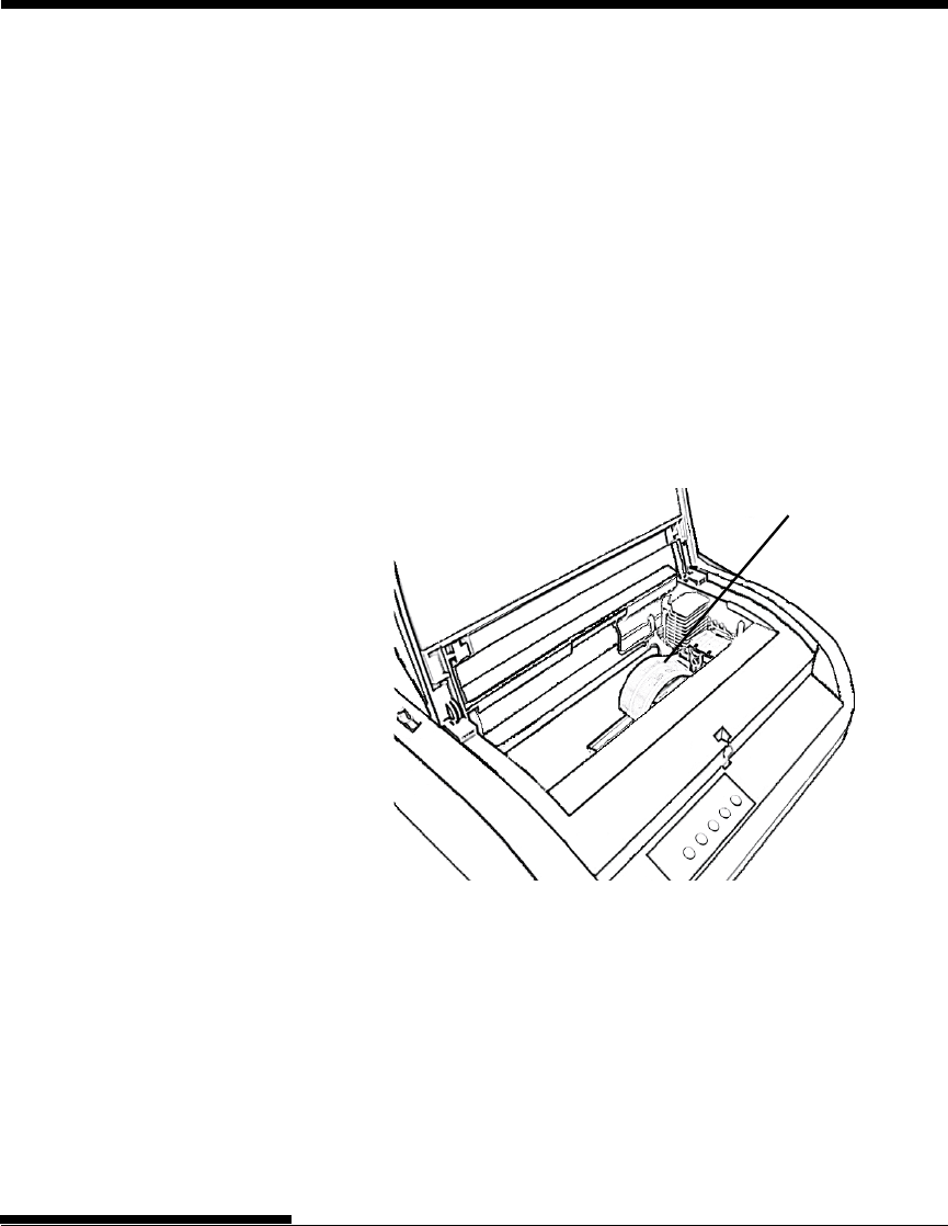
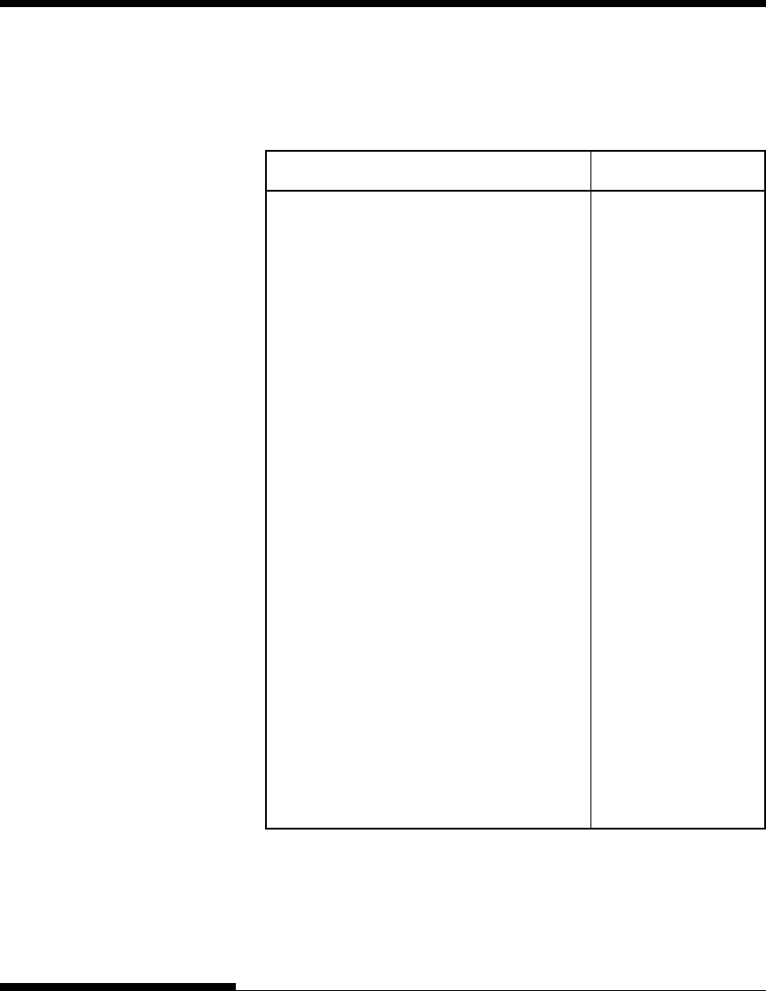
4. Open the front cover of the printer and remove the ribbon cartridge.
Using a soft vacuum brush, gently vacuum the platen, print head
carriage, and surrounding areas. You can easily slide the print head to
the left or right when the power is off. Be careful not to press too hard
on the flat ribbon cable that extends from the print head carriage.
Flat cable
Printer interior
5. Re-install the ribbon cartridge. Close the front cover.
6. Open the ejection cover. Vacuum the rollers, paper entry slot, and
surrounding areas.
7. Raise the cut sheet stand and the back cover. Vacuum the forms
tractors and surrounding areas.

Maintenance
User's Manual 6-3
MAINTENANCE
Cleaning the Platen and Paper Bail Rollers
Clean the platen and rollers about once a month to remove excess ink. Use
the platen cleaner recommended by your supplier and proceed as follows:
1. Apply a small amount of platen cleaner to a soft cloth. Avoid
spilling platen cleaner inside the printer.
CAUTION
Do not use alcohol to clean the platen. Alcohol may cause the
rubber to harden.
2. Place the cloth against the platen and manually rotate the platen
knob.
3. To dry the platen, place a dry cloth against the platen and manually
rotate the platen knob.
4. Gently wipe the rollers using the cloth moistened with the platen
cleaner. Dry the rollers using a dry cloth.
There are two ways of replacing the ribbon. You can install a new ribbon
cartridge in the printer or refill the old ribbon cartridge with new ribbon from
a ribbon subcassette. Appendix A lists order numbers for ribbon cartridges
and ribbon subcassettes. The following procedure is for ribbon cartridges.
For ribbon subcassettes, refer to the instructions shipped with the
subcassette.
To replace the ribbon cartridge:
1. Turn off the printer.
2. Open the front cover of the printer. For easy installation, slide the
print head carriage to a position where it does not face a roller.
CAUTION
The print head may be hot if you have been printing recently.
REPLACING THE RIBBON
User's Manual6-4
MAINTENANCE
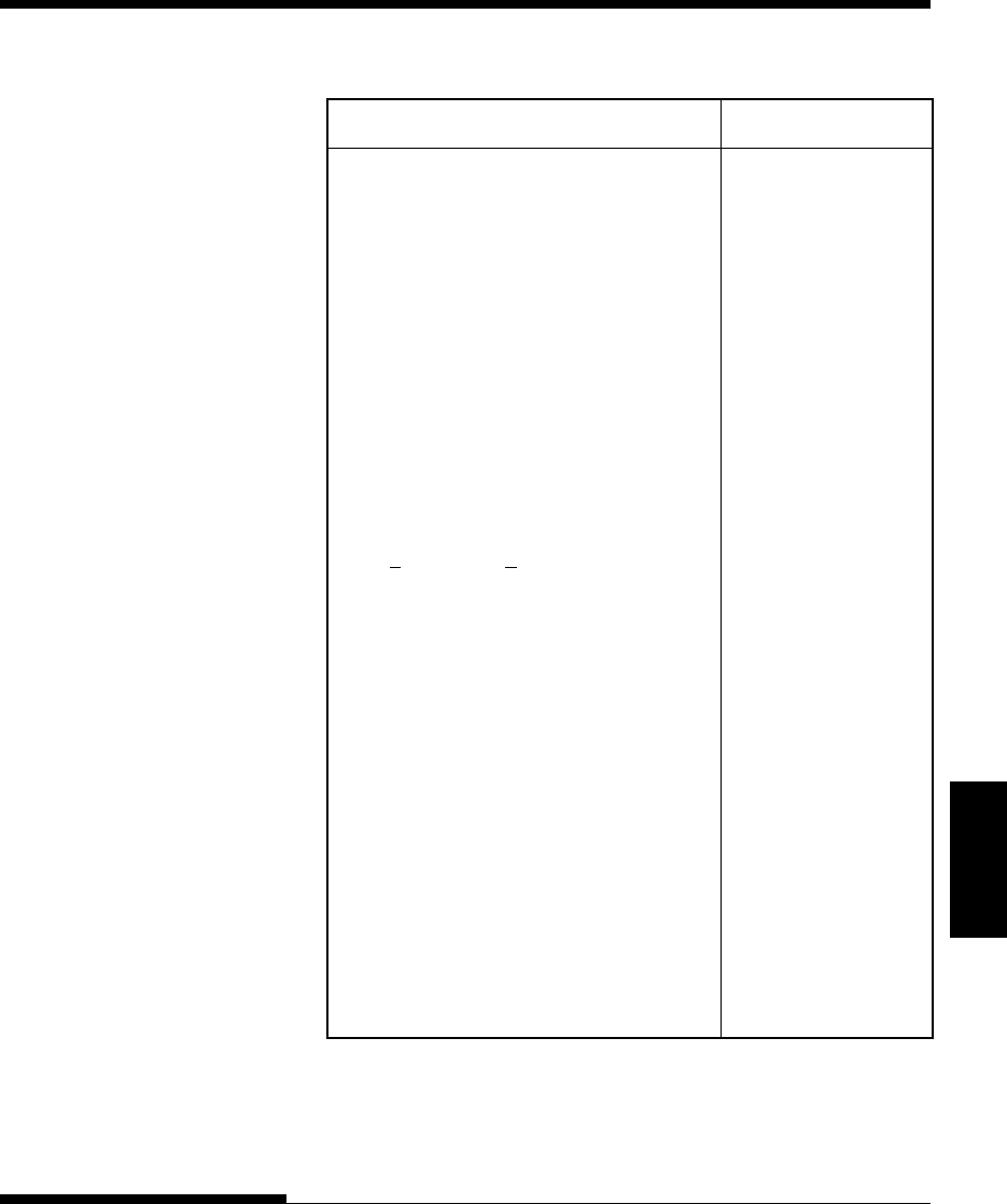
Removing the ribbon cartridge
Print guide
Print head
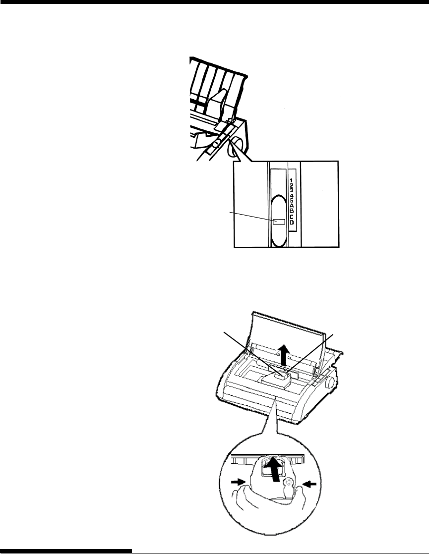
3. Move the paper thickness lever to position D.
Paper thickness lever
4. To remove the ribbon cartridge, press the ribbon release levers located
on either side of the cartridge and carefully lift the cartridge out of the
printer.
Paper thickness leve
r
Move to D.
Maintenance
User's Manual 6-5
MAINTENANCE
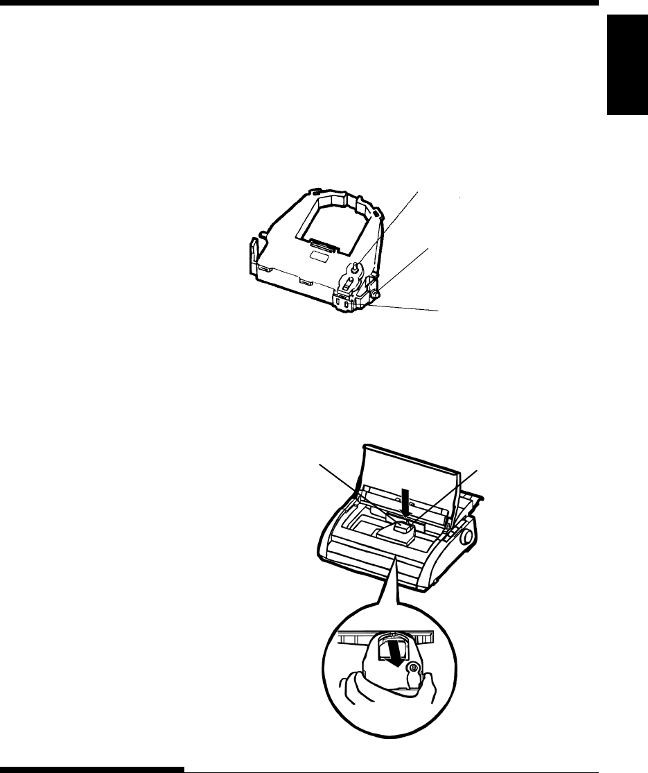
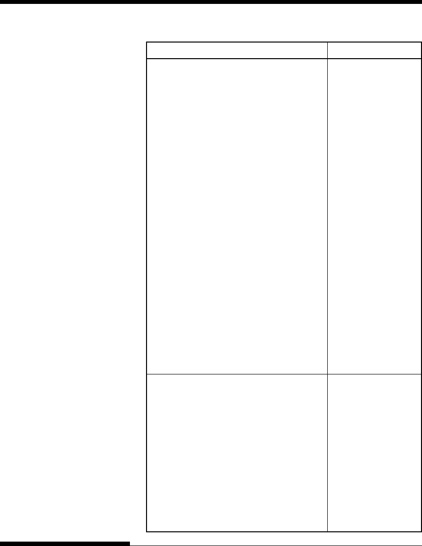
5. Remove the new ribbon cartridge from its package. Push in the sides
of the two ribbon release tabs. The tabs will snap into the cartridge
and the ribbon feed mechanism will engage.
Turn the ribbon feed knob clockwise to be sure that it feeds properly.
Ribbon feed knob
Turn clockwise
to tighten.
Ribbon release tabs
Preparing the new ribbon cartridge
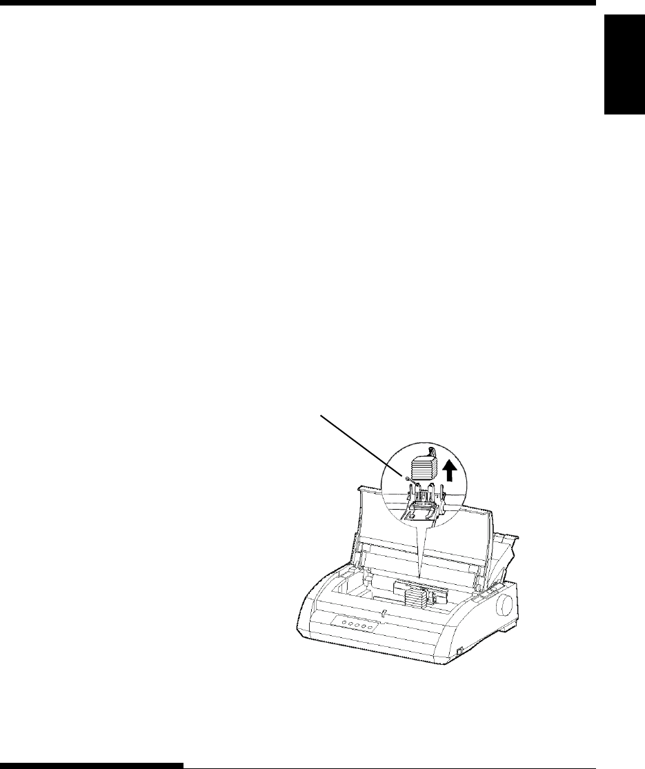
6. Place the two mounting pins on the ribbon support brackets of the
head carrier. The two mounting pins are located on the sides of the
ribbon release levers.) Insert the ribbon so that the ribbon falls
between the nose of the print head and the plastic print guide.
Munting pin
Print guide
Print head
Installing the new ribbon cartridge

User's Manual6-6
MAINTENANCE
7. Press the ribbon release levers until the mounting pins snap into the
holes on the ribbon support brackets. Gently pull on the cartridge to
verify that the pins are securely positioned in the holes.
8. Turn the ribbon feed knob clockwise to tighten the ribbon.
9. Move the paper thickness lever back to its original position. For
single sheet printing, the correct position is 1. Table 3.2 in Chapter 3
gives other paper thickness lever settings.
10. Close the front cover of the printer.
Maintenance
User's Manual 6-7
MAINTENANCE
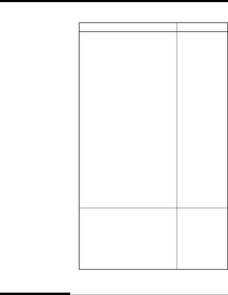
Head lock wire
REPLACING THE PRINT
HEAD
The print head is easy to replace.
CAUTION
The print head may be hot if you have been printing recently.
To remove the print head:
1. Turn off the printer.
2. Open the front cover of the printer and remove the ribbon cartridge.
3. Pull the right end of the head lock wire forward to release it from the
hook at the right of the print head carriage. Then release the wire
from the center hook.
4. Remove the print head from the connector on the carriage, as shown
in the figure below.
Replacing the print head

User's Manual6-8
MAINTENANCE
To install the print head:
1. Carefully fit the mounting guide grooves of the print head on the
locating studs on the carriage.
2. Push the print head into the connector and hook the wire into place in
the reverse order of removal.

User's Manual 7-1
Trouble-
shooting
TROUBLE-SHOOTING
TROUBLE-SHOOTING
Your printer is extremely reliable, but occasional
problems may occur. You can solve many of
these problems yourself, using this chapter.
If you encounter problems that you cannot resolve,
contact your dealer for assistance.
This chapter is organized as follows:
•Solving problems
•Diagnostic functions
•Getting help
The tables in this section describe common printer problems and their
solutions. The following types of problems are considered:
•Print quality problems
•Paper handling problems
•Operating problems
•Printer failures
Print Quality Problems
Poor print quality or other printing problems are often caused by incorrect
printer setup or incorrect software settings. A gradual decrease in print
quality usually indicates a worn ribbon. Table 7.1 identifies common print
quality problems and suggests solutions.
SOLVING PROBLEMS
7
TROUBLE-SHOOTING
7-2 User's Manual
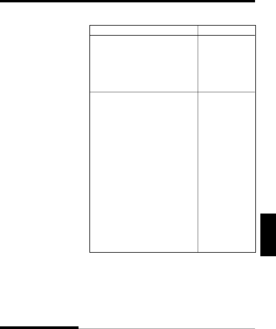
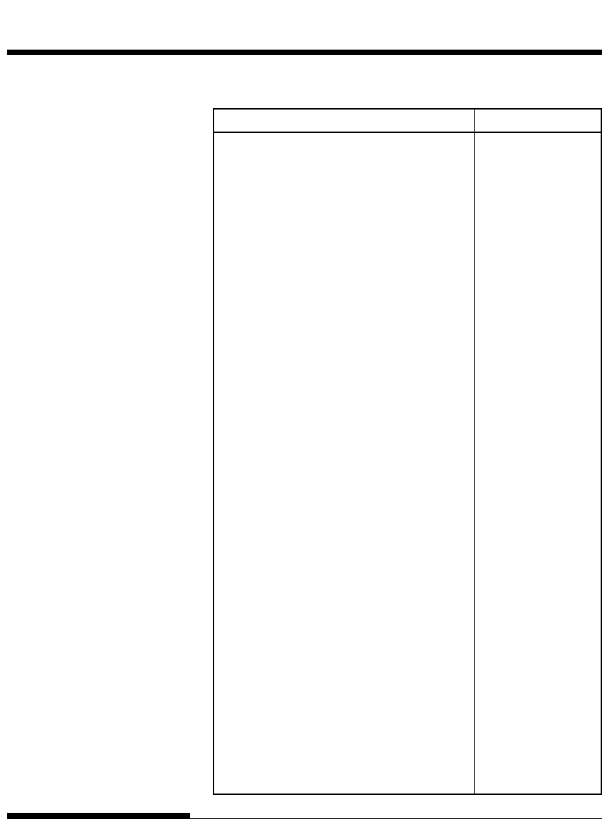
Table 7.1 Print Quality Problems and Solutions
Problem Solution
Printing is too Make sure that the ribbon cartridge is
light or too dark. properly installed and that the ribbon feeds smoothly.
Make sure that the paper thickness lever is set for the
thickness of your paper. See Table 3.2 in Chapter 3.
Check ribbon wear. Replace the ribbon if necessary.
Stains or smudges Make sure that the paper thickness lever is set
appear on the for the thickness of your paper. See Table 3.2 in
page. Chapter 3.
Check ribbon wear. Replace the ribbon if necessary.
Check whether the tip of the print head is dirty.
Clean the head with a soft cloth if necessary.
The page is blank. Make sure that the ribbon cartridge is properly
installed.
Printing is erratic Make sure that the interface cable is securely
or the wrong connected to both the printer and computer.
characters are
printed. Many Make sure that the printer emulation selected in
"?" characters are your software is the same as the emulation
printed. selected on the printer. See the section Selecting an
Emulation in Chapter 2.
If you are using an RS-232C serial interface, make
sure that the serial settings required by your software
or computer are the same as the settings on the
printer. See the section Changing Hardware
Options in Chapter 5.
User's Manual 7-3
Trouble-
shooting
TROUBLE-SHOOTING
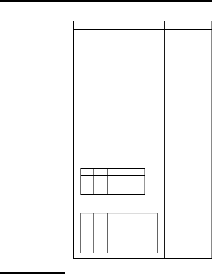
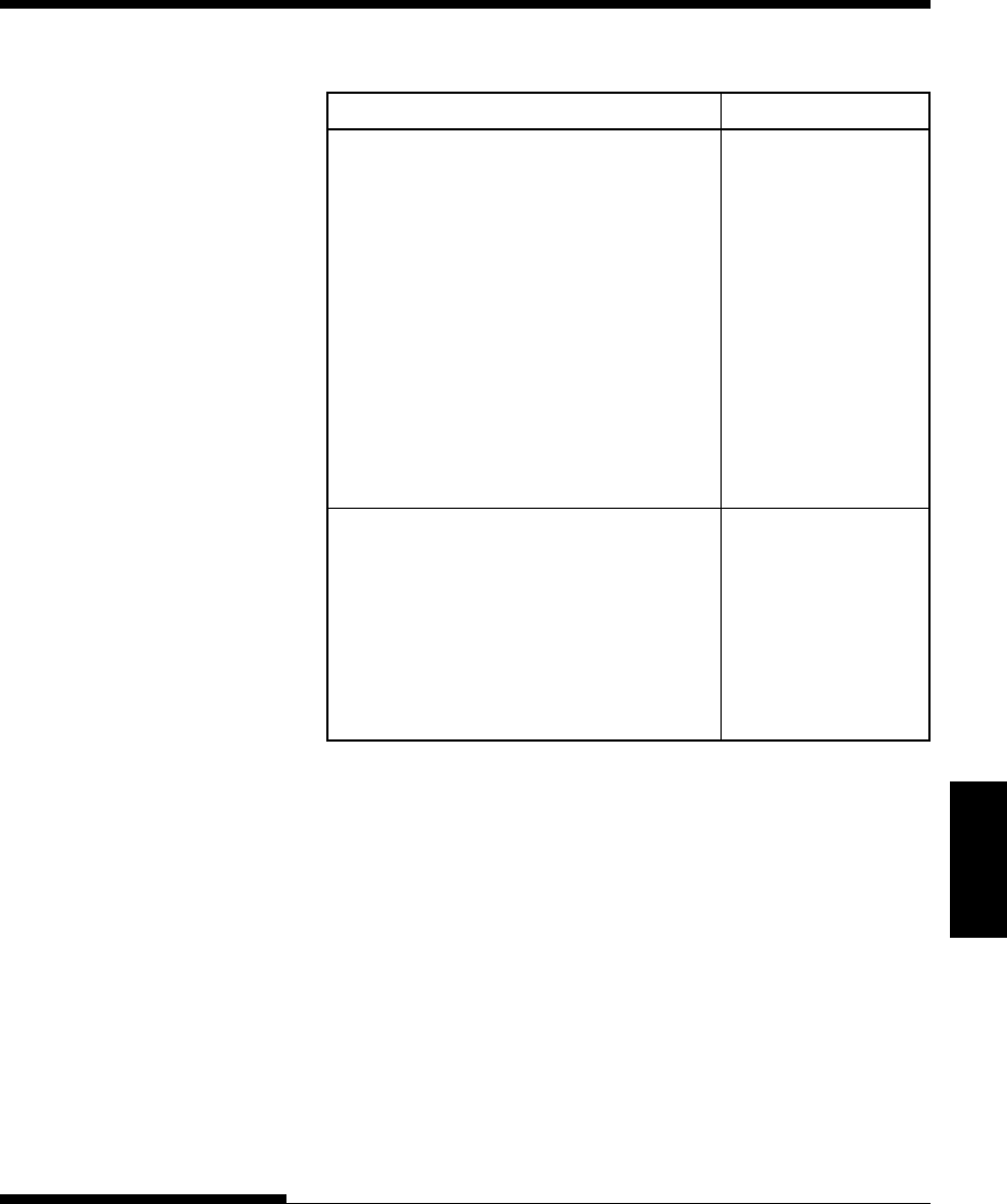
Table 7.1 Print Quality Problems and Solutions (Cont.)
Problem Solution
Printing is Use the printer’s V-ALMNT function to
vertically check the vertical print alignment. If necessary,
misaligned adjust the print alignment. See the section
(jagged). Using the Diagnostic Functions in Chapter 5.
The top margin is The top margin is the sum of the top-of-form
wrong. setting, the software-specified top margin, and the
printer’s TOP-MRG setting. Proceed as follows:
•Make sure that the top-of-form setting is
correct. The factory default is 25.4 mm (1
inch). See the section Changing Top-of
Form in Chapter 5.
•Check the software-specified top margin.
Refer to your software documentation.
•Check the printer’s TOP-MRG setting. See
the section Changing MENU1 and MENU2
Options in Chapter 5.
Lines are double Check the line spacing setting in your software.
spaced instead of
single spaced. Change the CR-CODE setting in the printer setup
mode to CR ONLY. See the section Changing
MENU1 and MENU2 Options in Chapter 5.
The printer Change the CR-CODE setting in the printer
overprints on the setup mode to CR & LF. See the section
same line. Changing MENU1 and MENU2 Options in
Chapter 5.
The next print line Change the LF-CODE setting in the printer
starts where the setup mode to LF & CR. See the section
previous line Changing MENU1 and MENU2 Options in
ended instead of Chapter 5.
at the left margin.
TROUBLE-SHOOTING
7-4 User's Manual
Paper Handling Problems
Table 7.2 describes common paper handling problems and suggests solutions.
See Chapter 3 for detailed procedures on loading and using paper.
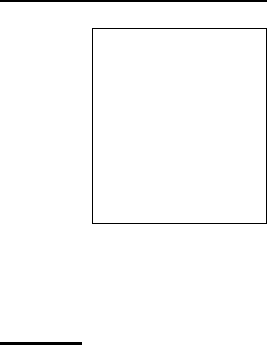
Table 7.2 Paper Handling Problems and Solutions
Problem Solution
Paper cannot be Make sure that the paper select lever is set
loaded or fed. correctly. Move the lever backward for continuous
forms and forward for single sheets.
Make sure that the paper covers the paper-out sensor,
i.e., the left paper edge is within 52 mm for single
sheets or 41 mm for continuous forms from the left
edge of the platen. (This problem cannot occur if
you use the forms tractor unit or insert a single sheet
with its left edge in contact with the left paper
guide.)
Make sure that the paper holder is closed and forms
tractors are positioned correctly to match the width
of your paper.

User's Manual 7-5
Trouble-
shooting
TROUBLE-SHOOTING
Table 7.2 Paper Handling Problems and Solutions (Cont.)
Problem Solution
Paper jams while Turn off the printer and remove the jammed
loading. paper. Remove any obstructions from the paper
path.
Make sure that the paper thickness lever is set for the
thickness of your paper. See Table 3.2 in Chapter 3.
Make sure that the paper is not folded, creased, or
torn.
Reload the paper.
Paper jams while Turn off the printer and remove the jammed
printing. paper. Remove any obstructions from the paper
path.
Make sure that the paper thickness lever is set for the
thickness of your paper. See Table 3.2 in Chapter 3.
For continuous forms, make sure that the incoming
and outgoing paper stacks are correctly placed.
Paper should feed straight.
Paper slips off the Make sure that the forms tractors are positioned
forms tractors or correctly for the width of your paper and that
the perforated the perforated holes of the paper fit directly over
holes of the paper the tractor sprockets.
tear during
printing.
TROUBLE-SHOOTING
7-6 User's Manual
Tips for clearing a jammed sheet from the printer
If a sheet of paper is jammed between the print head and the platen and
cannot be removed, clear it as follows:
1. Turn off the printer and disconnect the power cord from the
receptacle.
2. Push up the locking levers to rlease the forms tractors and open the
paper holders.
3. Move the paper thickness lever to position D.
4. Move the print head so that you can remove the jammed sheet easily
and clear the sheet.
NOTE
The print head is hot immediately after printing. Move it after making
sure that it gets cool.
•If you cannot clear the
jammed sheet by the
above procedure, set
fourfold continuous
forms paper on the
forms tractors and turn
the platen knob to feed
the paper forward. The
jammed paper is pushed
out. Before operation, be sure to position the print head at the
center of the jammed paper.

User's Manual 7-7
Trouble-
shooting
TROUBLE-SHOOTING
Operating Problems
If any of the errors listed in Table 7.3 occurs, the PAPER OUT LED lights
up, and an alarm beeps, and the printer goes offline.
In such cases, the buttons on the control panel can be used in the same
manner as those when the printer is in the offline state.
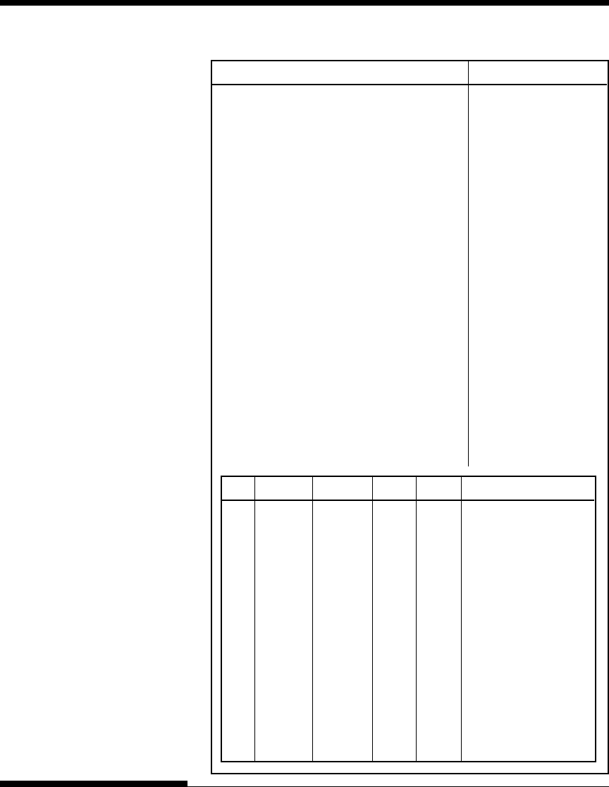
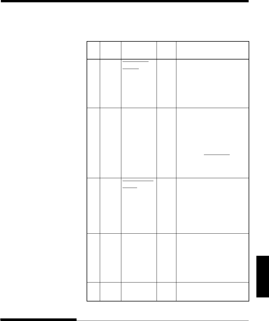
Table 7.3 Operating Problems and Solutions
Paper end (PE) error
Paper end is detected.
(*1)
-
Insert and load the
paper in the paper tray.
Eject jam error
Paper end is not detected
- Eject forms or sheets.
even after a large amount
- Press the online button
of continuous forms or cut
to turn the printer online.
sheets were ejected.
Continuous form/
In continuous form loading
- Switch the continuous
cut sheet switch status, the continuous form/
form/cut sheet switch
lever
error cut sheet switch lever is
lever back to its original
switched to cut sheet mode.
position.
In cut sheet loading status,
- Remove the loaded
the continuous form/cut
paper.
sheet switch lever is switched
to continuous form mode.
If the error occurs, all
buttons are disabled.
Load jam error
After the tractor PE sensor
- Execute the loading
detected the form at continuous
operation.
form loading, the TOF sensor
- Press the online button
does not detect the top of the
to turn the printer
form even after line feed is
online.
executed a certain number of - When the cut sheets are
times.
loaded, remove the
After the set sensor detects the
sheets once, and
sheet at cut sheet
then insert them again.
loading, the TOF sensor
They are then loaded
does not detect
he top of
automatically.
the sheet even after line
feed is executed a certain
number of times.
Error name Error description Recovery method
TROUBLE-SHOOTING
7-8 User's Manual
Error name Blink Light
ONLINE AREA OVER PAPER OUT
Paper end *
Eject jam error * *
Continuous form/
cut sheet switch * *
lever error
Load jam error *
*1 If the setup item PPR-OUT:IGNORE is specified, paper end is not
detected.
LED status
LEDs light up depending on the following error types.
User's Manual 7-9
Trouble-
shooting
TROUBLE-SHOOTING
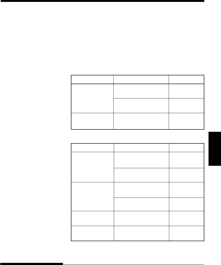
Printer Failures
A user cannot generally resolve a problem involving defective printer
hardware. On detecting a fatal error, the printer will:
•Stop printing
•Beep four times
•Turn the ONLINE indicator off
•Blink the PAPER OUT indicator (see Table 7.4 for the error type).
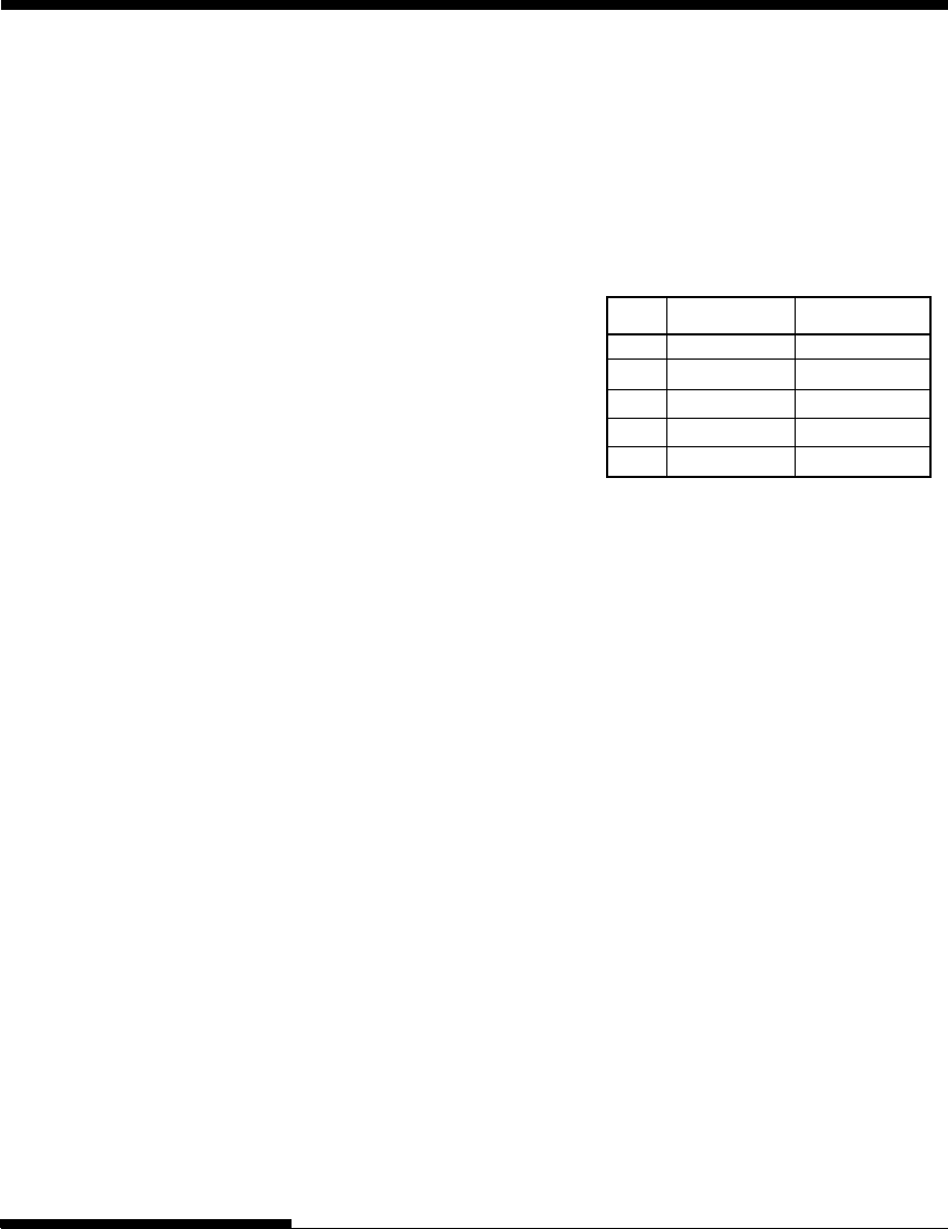
Table 7.4 Printer Failures
Error LED states
<Lit> <Blinking>
+34 V undervoltage error ONLINE PAPER OUT
Left end sensor error MENU1 PAPER OUT
Overload printing error MENU2 PAPER OUT
RAM error AREA OVER PAPER OUT
The following errors cause the printer to turn off the power:
•Print head error
•Space motor error
•Line feed motor error
•+34 V overvoltage error
No error condition is displayed if any of these errors occurs.
Turn the printer off and back on, then rerun the same job to check if the error
was transient. If the error recurs, contact your dealer.

TROUBLE-SHOOTING
7-10 User's Manual
The printer diagnostic functions are SELF-TST, HEX-DUMP, and
V-ALMNT.
•SELF-TST tells you whether the printer hardware is functioning
correctly. If the printer hardware is functional, any problems you are
having are probably caused by incorrect printer settings, incorrect
software settings, the interface, or the computer.
•HEX-DUMP allows you to determine whether the computer is
sending the correct commands to the printer, and whether the printer
is executing the commands correctly. This function is useful to
programmers or others who understand how to interpret hex dumps.
•V-ALMNT allows you to check and, if necessary, correct the printer’s
vertical print alignment.
For details on using these functions, all of which are available in the printer
setup mode, see the section Using the Diagnostic Functions in Chapter 5.
If you are not able to correct a problem using this chapter, contact your dealer
for assistance. Be prepared to provide the following information:
•Your printer model number, serial number, and date of manufacture.
Look for this information on the rating label on the left side of the
printer.
•Description of the problem
•Type of interface you are using
•Names of your software packages
•List of the printer default settings. To print the default settings, see
the section Printing a List of Selected Options in Chapter 5.
DIAGNOSTIC
FUNCTIONS
GETTING HELP
User's Manual A-1
Supplies
SUPPLIES AND OPTIONS
This appendix lists the supplies, options, and
programmer’s manuals available for the printer.
Contact your dealer for information on ordering
any of these items.
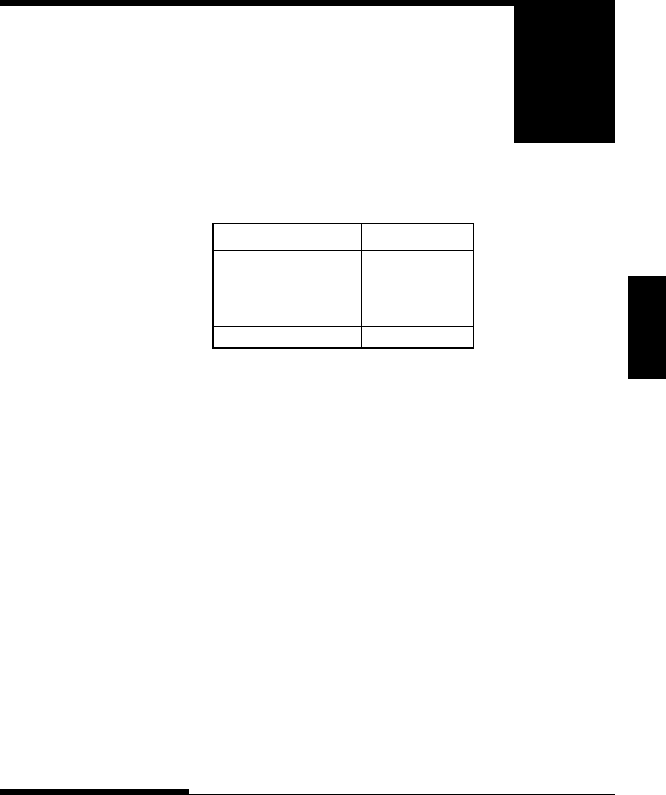
Supplies Order Number
Ribbon cartridges
Black ribbon CA02374-C104
Ribbon subcassette
Black ribbon CA02374-C204
Print head CA02281-E718
Option Order Number Description
RS-232C serial interface board.
SUPPLIES
A
USER OPTION

SUPPLIES AND OPTIONS
A-2 User's Manual

Specifications
User's Manual B-1
PRINTER AND PAPER SPECIFICATIONS
B
APPENDIX
PHYSICAL
SPECIFICATIONS
PRINTER AND PAPER
SPECIFICATIONS
This appendix gives the physical, functional, and
performance specifications for the printer.
It also gives detailed paper specifications.
Dimensions Height: 120 mm (4.72 in)
Width: 415mm (16.3 in)
Depth: 330 mm (13 in)
Weight: 7.5 kg (16.5 lb)
AC power requirements
Model: M33331A
100 to 120 VAC ±10%; 50/60 Hz
Model: M33331B
220 to 240 VAC –10%, +6%; 50/60 Hz
Power consumption Average 120 VA
Maximum 240 VA
Heat generation Average 65 kcal/h
Interface Centronics parallel
Centronics parallel and RS-232C serial
Centronics parallel and USB
Data buffer size 0, 256, 2K, 8K, 24K, 32K, 96K or 128K bytes
Download buffer Maximum 128K bytes
(128K minus data buffer size)
Operating environment 5 to 38½C (41 to 100½F)
30% to 80% RH (no condensation)
Wetbulb temperature, less than 29½C (84½F)
Storage environment –15 to 60½C (–4 to 140½F)
10% to 95% RH (no condensation)
Acoustic noise Average 49 dBA when printing in letter
quality
ISO 7779 (Bystander Position Front)
B

PRINTER AND PAPER SPECIFICATIONS
B-2 User's Manual
FUNCTIONAL
SPECIFICATIONS
Print method Impact dot matrix with a 0.2 mm, 24-wire
head
Print direction Bidirectional logic-seeking or unidirectional
seeking
Character cell Horizontal ¥ vertical
Letter (10 cpi): 36 ¥ 24 dots
Letter (12 cpi): 30 ¥ 24 dots
Report: 18 ¥ 24 dots
Draft: 12 ¥ 24 dots
High-speed draft: 9 ¥ 24 dots
Paper handling Standard: Friction-feed platen (cut sheets)
Push tractors (rear feed of continuous forms)
Paper loading by LOAD button
Advancing perforations to tear-off edge by
TEAR OFF button
Parking continuous forms when using cut
sheets
Paper type 1-to 5-part side-glued or paper-stapled
fanfolded continuous forms or label sheets
with sprocket holes
1-to 5-part top-glued cut sheets and
envelopes
Paper size
Continuous Width: 102–267 mm
(4–10.5 in)
Length: 102 mm (4 in)
or greater
Cut sheets Width: 102–267 mm
(4–10.5 in)
Length: 76–364 mm
(3–14.3 in)
Paper thickness Up to 0.35 mm (0.014 inch)

Specifications
User's Manual B-3
PRINTER AND PAPER SPECIFICATIONS
Paper length
By software Programmable in one line or inch increments
in all emulations
By control panel Depends upon emulations. Default is 11
inches for all emulations.
DPL24C+/XL24E: 3, 3.5, 4, 5, 5.5, 6, 7, 8, 8.5, 11, 11.6, 12, 14,
or 18 inches
ESC/P2: 4, 4.5, 5, 5.5, ..., 11, 11.5, ..., 22 inches
Number of copies Up to 5, including the original
Command sets (emulations)
Resident Fujitsu DPL24C PLUS
IBM Proprinter XL24E
Epson ESC/P2
Character sets
DPL24C+/XL24E: •IBM PC character sets 1 and 2
•IBM PS/2 character sets (code pages 437,
850, 852, 855, 860, 863, 865, 866, and
DHN)
IBM 437 and 851
ISO 8859-1 and ECMA 94
Total of 59 national character sets
•Fujitsu character sets (691 characters)
ESC/P2: •Italic character set
Graphics character sets 1 and 2
•IBM PS/2 character sets (code pages 437,
850, 852, 855, 860, 863, 865, 866, and
DHN)
IBM 437 and 851
ISO 8859-1 and ECMA 94
Total of 63 national character sets

PRINTER AND PAPER SPECIFICATIONS
B-4 User's Manual
Fonts
Resident Eighteen fonts available
Bit map: Courier 10, Pica 10, OCR-B 10, OCR-A 10,
Prestige Elite 12, Boldface PS, Correspond-
ence, Compressed, Draft, and High-speed
Draft
Outline: Courier, Timeless, and Nimbus Sans ®;
each in normal, bold, and italic styles
Downloaded Available from independent vendors
Line spacing 1, 2, 3, 4, 5, 6, 7, or 8 lines per inch.
Programmable in 1/360 inch or various
increments for image graphics.
Character pitch 2.5, 3, 5, 6, 10, 12, 15, 17.1, 18, or 20 cpi,
or proportional spacing.
Programmable in 1/360 inch or various
increments for image graphics.
Characters per line
10 cpi: 80 cpl
12 cpi: 96 cpl
15 cpi: 120 cpl
17.1 cpi: 136.8 cpl
18 cpi: 144 cpl
20 cpi: 160 cppl
cpi: characters per inch
cpl: characters per line
Print speed 10 cpi 12 cpi
Letter: 113 cps 135 cps
Report: 225 cps 270 cps
Correspondence: 225 cps 270cps
Draft: 360 cps 432 cps
High-speed draft: 400 cps 480 cps
cpi: characters per inch
cps: characters per second
Line feed speed 80 ms per line at 6 lines per inch
PERFORMANCE
SPECIFICATIONS
Specifications
User's Manual B-5
PRINTER AND PAPER SPECIFICATIONS
Form feed speed 5.6 inches per second
Ribbon life
Up to 5.0 million characters
Certification
Safety:
Model Regulation Country
M33331A UL 1950-D3 United States
(for 100 to 120 VAC)
CSA C22.2/950 Canada
(for 100 to 120 VAC)
M33331B TÜV EN60950 Germany
(for 220 to 240 VAC) Europe
EMI regulation:
Model Regulation Country
M33331A FCC Part 15B class B United States
(for 100 to 120 VAC)
ICES-003 class B Canada
(for 100 to 120 VAC)
M33331B EN 55022 class B Europe
(for 220 to 240 VAC)
AS/NZS 3548 class B Australia and
(for 220 to 240 VAC) New Zealand
M33331A CNS 13438 class B Asia
(for 100 to 120 VAC)
M33331B CNS 13438 class B Taiwan
(for 220 to 240 VAC)
PRINTER AND PAPER SPECIFICATIONS
B-6 User's Manual
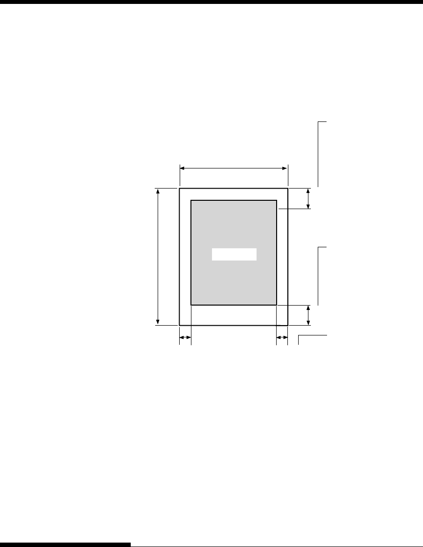
PAPER SPECIFICATIONS Print Area
This section illustrates the recommended print area for single sheets and
continuous forms.
Print area for single sheets
May be
decreased to
4.23 mm
(1/6 inch).
However, line
spacing may be
uneven.
May be decreased
to 8.5 mm
(1/3 inch).
However, line
spacing may be
uneven.
Print area may be
off the paper,
depending on
paper setting or
width.
25.4 mm (1 inch)
25.4 mm (1 inch)
Print area
5.08 mm or more
(0.2 inch or more)
HH
HH
102-266.7 mm (4-10.5 in)
76-364 mm (3-14.3 in)
5.08–32 mm (0.2–1.26 in)
Specifications
User's Manual B-7
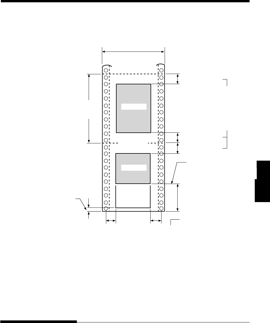
PRINTER AND PAPER SPECIFICATIONS
Print area for continuous forms
Print area
May be
decreased to
4.23 mm
(1/6 inch).
However, line
spacing may be
uneven.
Perforation
5.08 mm or more
(0.2 inch or
102 mm
(4 inches)
or more
Paper end
25.4 mm (1 inch)
Print area may be off the
paper, depending on
paper setting or width.
Print area
102-266.7 mm (4-10.5 in)
5.08-25.4 mm (0.2-1 in)
Approx. 80 mm (3.2 inches)
25.4 mm (1 inch)
25.4 mm (1 inch)
Print head position when
paper end is detected,
selectable by setup mode.
Printing
resumable
Approx. 4.7 mm (0.18 inches):
Resume printing is allowable
to single-part paper only and
selectable by setup mode.
PRINTER AND PAPER SPECIFICATIONS
B-8 User's Manual
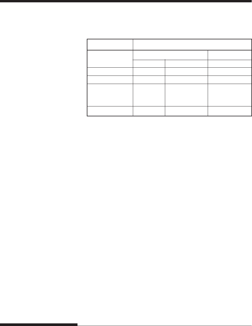
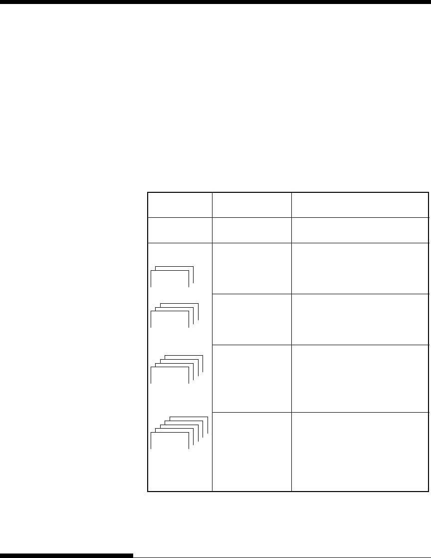
Paper Thickness
Paper thickness is given by the weight of the paper in either grams per
square meter (g/m2) or in pounds per bond (lbs/bond). The following
table shows the allowable paper thickness for one-part paper or for each
sheet of multipart paper. The total thickness must not exceed 0.35 mm
(0.014 inch).
The weight of carbonless or carbon-backed paper may vary, depending
upon the paper manufacturer. When using paper of borderline thickness,
test the paper before running a job.
Type of Paper Number of Parts Thickness
One-part Single 47-81 g/m2 (40-70 kg or 12-22 lb)
Carbonless
Top 40-64 g/m2 (34-55 kg or 11-17 lb)
Bottom 40-81 g/m2 (34-70 kg or 11-22 lb)
Top 40-64 g/m2 (34-55 kg or 11-17 lb)
Middle 40-64 g/m2 (34-55 kg or 11-17 lb)
Bottom 40-81 g/m2 (34-70 kg or 11-22 lb)
Top 40-64 g/m2 (34-55 kg or 11-17 lb)
Middle 40-64 g/m2 (34-55 kg or 11-17 lb)
Middle 40-64 g/m2 (34-55 kg or 11-17 lb)
Bottom 40-81 g/m2 (34-70 kg or 11-22 lb)
Top 40-52 g/m2 (34-45 kg or 11-17 lb)
Middle 40-52 g/m2 (34-45 kg or 11-17 lb)
Middle 40-52 g/m2 (34-45 kg or 11-17 lb)
Middle 40-52 g/m2 (34-45 kg or 11-17 lb)
Bottom 40-64 g/m2 (34-55 kg or 11-17 lb)
5P
4P
3P
2P
kg: Weight in kilograms of 1000 sheets of 788 ¥ 1091 mm paper
(1.16 g/m2)
lb: Weight in pounds of 500 sheets of 17 ¥ 22 inch paper (3.76 g/m2)
Specifications
User's Manual B-9
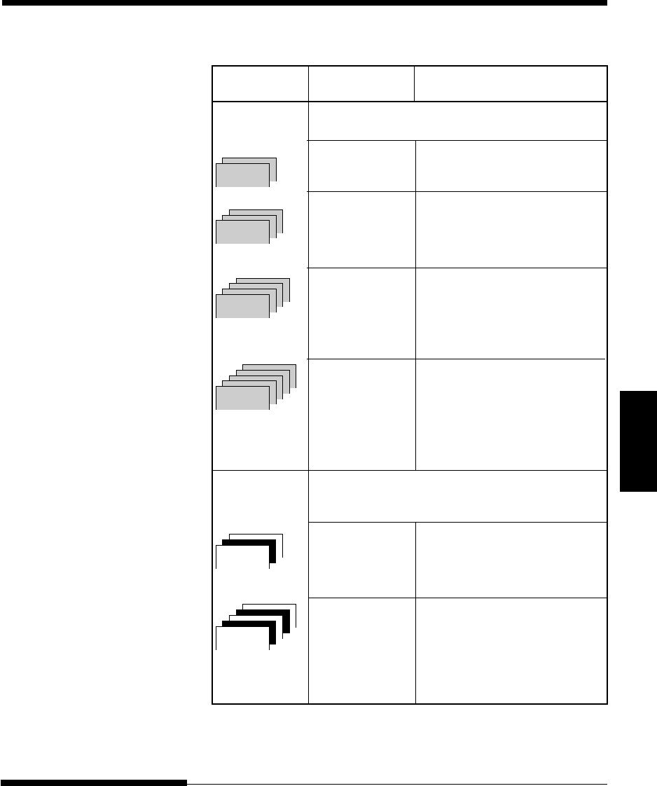
PRINTER AND PAPER SPECIFICATIONS
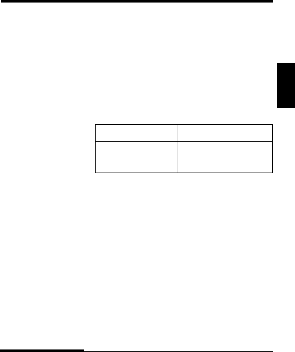
Type of Paper Number of Parts Thickness
Carbon-backed Do not use in high humidity environments.
Top 40-64 g/m2 (34-55 kg or 11-17 lb)
Bottom 40-81 g/m2 (34-70 kg or 11-22 lb)
Top 40-64 g/m2 (34-55 kg or 11-17 lb)
Middle 40-64 g/m2 (34-55 kg or 11-17 lb)
Bottom 40-81 g/m2 (34-70 kg or 11-22 lb)
Top 40-64 g/m2 (34-55 kg or 11-17 lb)
Middle 40-64 g/m2 (34-55 kg or 11-17 lb)
Middle 40-64 g/m2 (34-55 kg or 11-17 lb)
Bottom 40-81 g/m2 (34-70 kg or 11-22 lb)
Top 40-52 g/m2 (34-45 kg or 11-14 lb)
Middle 40-52 g/m2 (34-45 kg or 11-14 lb)
Middle 40-52 g/m2 (34-45 kg or 11-14 lb)
Middle 40-52 g/m2 (34-45 kg or 11-14 lb)
Bottom 40-64 g/m2 (34-55 kg or 11-17 lb)
Carbon- Avoid using carbon-interleaved single sheets.
interleaved
Top 35-64 g/m2 (30-55 kg or 9-17 lb)
Carbon Counted as one sheet
Bottom 35-81 g/m2 (30-70 kg or 9-22 lb)
Top 35-52 g/m2 (30-45 kg or 9-14 lb)
Carbon Counted as one sheet
Middle 35-52 g/m2 (30-45 kg or 9-14 lb)
Carbon Counted as one sheet
Bottom 35-64 g/m2 (30-55 kg or 9-17 lb)
kg: Weight in kilograms of 1000 sheets of 788 ¥ 1091 mm paper
(1.16 g/m2)
lb: Weight in pounds of 500 sheets of 17 ¥ 22 inch paper (3.76 g/m2)
3P
2P
5P
5P
4P
4P
3P
3P
2P
2P
5P
4P
3P
2P

PRINTER AND PAPER SPECIFICATIONS
B-10 User's Manual

C-1
Command
Sets
User's Manual
COMMAND SETS
C
COMMAND SETS
This appendix describes printer commands and
their parameters.
This printer has three resident command sets:
•Fujitsu DPL24C PLUS (native command set for Fujitsu DL series
printers)
•IBM Proprinter XL24E
•Epson ESC/P2
Select the same emulation on the printer and in your software. If your
software emulations include DPL24C PLUS, select DPL24C PLUS for
optimum performance.
C-2 User's Manual
COMMAND SETS (DPL24C PLUS)
FUJITSU DPL24C
PLUS
This section describes the printer commands for the DPL24C PLUS com-
mand set which is the native command set of this printer.
Function Command
Print Mode Control
Double-strike (bold) printing on ESC G
Double-strike (bold) printing off ESC H
Emphasized (shadow) printing on ESC E
Emphasized (shadow) printing off ESC F
Italic printing on ESC 4
Italic printing off ESC 5
Select character style and screening ESC e S (n1) (n2)
n1 = 0: Normal
1: Outline
2: Shaded
3: Outline and shaded
4: Thin outline
5: Thin shaded
6: Thin outline and shaded
n2 = 0: Transparent
1: Light dot matrix
2: Heavy dot matrix
3: Vertical bars
4: Horizontal bars
5: Slants
6: Back slants
7: Lattice
One-line double width characters on SO or ESC SO
One-line double width characters off DC 4
Double width characters on/off ESC W (n)
(on: n = 1, off: n =0)
C-3
Command
Sets
User's Manual
COMMAND SETS
Function Command
Double-height characters on/off ESC V (n)
(on: n = 1, off: n =0)
This command does not adjust the line
spacing.
Multiwidth and height printing ESC u (n) (h1) (h2)
n = 0: Not adjusted (v1) (v2)
1: Character pitch multiplied
2: Line spacing multiplied
3: Character pitch and line spacing
multiplied
h1: Tens digit of horizontal multiple
h2: Units digit of horizontal multiple
v1: Tens digit of vertical multiple
v2: Units digit of vertical multiple
(0 < h1 h2 or v1 v2 < 11)
Condensed characters on SI or ESC SI
Condensed characters off DC2
Subscript or superscript printing on ESC S (n)
(subscript: n=1, superscript: n=0)
Subscript and superscript printing off ESC T
Select underline type ESC e U (n)
n = 0: Single line
1: Bold single line
2: Extremely bold single line
3: Double line
4: Bold double line
5: Extremely bold double line
Underline on/off ESC – (n)
(on: n=1, off: n=0)
Overline on/off ESC e o (n)
(on: n=1, off: n=0)
C-4 User's Manual
COMMAND SETS (DPL24C PLUS)
Function Command
Select printing style ESC ! (n)
This command allows you to combine
various printing styles. The value of n is
the sum of the values of the styles you
want to combine.
n = 0: Pica pitch
1: Elite pitch
4: Condensed
8: Shadow
16: Bold
32: Double width
64: Proportional
Select image overlay type ESC e I (n)
This command allows you to overlay a
pattern on characters.
n = 1: Light dot matrix
2: Heavy dot matrix
3: Vertical bars
4: Horizontal bars
5: Slants
6: Back slants
7: Lattice
Image overlay printing on/off ESC e L (n)
(on: n=1, off: n=0)
Horizontal Control
Space SP
Backspace BS
Carriage return CR
Elite pitch (12 cpi) ESC M
Pica pitch (10 cpi) ESC P
Proportionally spaced characters on/off ESC p (n)
(on: n=1, off: n=0)
Set character pitch to (n-1)/120 inch ESC US (n)
(1 - n - 127)
Set character pitch to n/180 inch ESC h (n)
(0 - n - 255)

C-5
Command
Sets
User's Manual
COMMAND SETS
Function Command
Set character offset to n/120 inch ESC DC1 (n)
Cancelled by CR or ESC x.
(0 - n - 63) (64 - n - 127)
Set character pitch to n/360 inch ESC e H
(0 - n1 n2 n3 - 999) (n1) (n2) (n3)
n1, n2, and n3 are the hundreds, tens, and
units digits.
Vertical Control
Line feed LF
Reverse line feed ESC LF
Form feed FF
Advance paper n/180 inch (0 - n - 255) ESC J (n)
Reverse paper n/180 inch (0 - n - 255) ESC j (n)
Advance paper n/360 inch ESC e J
(0 - n1 n2 n3 - 999) (n1) (n2) (n3)
n1, n2, and n3 are the hundreds, tens, and
units digits.
Reverse paper n/360 inch ESC e j
(0 - n1 n2 n3 - 999) (n1) (n2) (n3)
n1, n2, and n3 are the hundreds, tens, and
units digits.
Set line spacing to 1/8 inch (8 lpi) ESC 0
Set line spacing to n/180 inch ESC 3 (n)
(0 - n - 255)
Set line spacing to 7/60 inch ESC 1
Set line spacing to n/60 inch ESC A (n)
(0 - n - 127)
Set line spacing to 1/6 inch (6 lpi) or to the ESC 2
value set with the ESC A command.
The preset line spacing command is
ESC A (n).
Set line spacing to n/360 inch ESC e V
(0 - n1 n2 n3 - 999) (n1) (n2) (n3)
n1, n2, and n3 are the hundreds, tens, and
units digits.
Set line spacing to n/360 inch FS 3 (n)
(1 - n - 255)
C-6 User's Manual
COMMAND SETS (DPL24C PLUS)
Function Command
Tabulation
Horizontal tab execution HT
Set horizontal tabs ESC D (n1) ... (nk)
The values of n1 to nk in this command NUL
are the ASCII values of the print
columns (at the current character width)
at which tabs are to be set.
(1 - n - 255) (1 - k - 255)
Move to print column n (1 - n - 255) ESC HT (n)
Move dot column n/360 inch ESC $ (n1) (n2)
(n = n1 + n2 x 256)
The value below is for 136-column printers.
(0 - n1 255) (0 - n2 - 19)
(0 - n2 x 256 + n1 - 4895)
Horizontal relative move by n/360 inch ESC e R (s)
(–999 - n1 n2 n3 - +999) (n1 ) (n2) (n3)
n1, n2, and n3 are the hundreds, tens, and
units digits of the distance. s is a plus
or minus ( + or –) sign.
Vertical tab execution VT
Set vertical tabs ESC B (n1) ... (nk)
The values of n1 to nk in this command NUL
are the ASCII values of the lines (at the
current line spacing) at which tabs are
to be set.
(1 - n - 255) (1 - k - 64)
Move to line n (1 - n - 255) ESC VT (n)
Page Formatting
Set right margin (0 - n - 255) ESC Q (n)
Set left margin (0 - n - 255) ESC l (n)
Set perforation skip by n lines ESC N (n)
(1 - n - 127)
Perforation skip off ESC O
Set page length to n lines ESC C (n) or
(1 - n - 127) ESC e C (n) or
ESC FF (n)
C-7
Command
Sets
User's Manual
COMMAND SETS
Function Command
Set page length to n inches ESC C NUL (n) or
(1 - n - 22) ESC e C NUL (n) or
ESC FF NUL (n)
Set page length to n/360 inch ESC e f (n1) (n2)
(n = n1 ¥ 256 + n2)
(0 - n1 n2 - 255)
(1 - n1 ¥ 256 + n2 - 7920)
Character Set Control
Select character set 1 ESC 7
Appendix E gives the character sets
Select character set 2 ESC 6
Appendix E gives the character sets.
Select international character set ESC R (n)
n = 0: USA
1: France
2: Germany
3: United Kingdom
4: Denmark 1/Norway
5: Sweden/Finland
6: Italy
7: Spain
8: Denmark 2
Clear print buffer CAN
Select printer DC1
Deselect printer (ignore input) DC3
Force most significant bit to 1 ESC >
Force most significant bit to 0 ESC =
Cancel control over most significant bit ESC #
C-8 User's Manual
COMMAND SETS (DPL24C PLUS)
Function Command
Select code table ESC e C (n)
n = 0: Code page 437
1: Code page 850
2: Code page 860
3: Code page 863
4: Code page 865
5: ISO 8859-1/ECMA 94
Select extended character by character ESC e E
number (n1) (n2) (n3)
(0 £ n1n2n3 £ 664)
n1, n2, and n3 are the hundreds, tens, and
units digits.
Word Processing
Line justification on ESC m
Automatically center printing ESC c
Reset word processing features ESC x
Font Selection and Downloading
Select font m with source and style set by n ESC % (m) (n)
•m (bits 0 and 1: Font device selection)
Bit 1 Bit 0 Selection of font
0 0 Resident font
0 1 Downloaded font
1 0 Resident font
•m (bits 2 and 3: Print quality specification
Bit 3 Bit 2 Print quality
0 0 Original quality of font
0 1 Letter quality (360 dpi)
1 0 Correspondence
quality (180 dpi)
1 1 Draft quality (120 dpi)

C-9
Command
Sets
User's Manual
COMMAND SETS
Function Command
• n (bit 0 to 2: Specification of font number)
(1) Resident fonts
nm = 0, 0 m = 1, 0
0 Courier 10 OCR-B
1 Prestige elite 12 OCR-A
2 Draft
3 Compressed
4 Boldface PS
5 Pica 10
6 Correspondence
7 High-speed draft
(2) Downloaded fonts
n = 0: Downloaded font 0
1: Downloaded font 1
Select print quality (font attributes) ESC e q (n)
n = 0: Letter (360 ¥ 180 dpi)
1: Correspondence (180 ¥ 180 dpi)
2: Draft (120 ¥ 180 dpi)
3: High-speed Draft (90 ¥ 180 dpi)
Select spacing mode (font attributes) ESC e s (n)
n = 0: Fixed pitch font
1: Proportional spacing font
Select character pitch (n/360 inch, font ESC e p (n1) (n2)
attributes)
(0 - n1 - 255) (1 - n2 - 255)
(n = n1 ¥ 256 + n2)
Ex. n = 36: 10 pitch
30: 12 pitch
24: 15 pitch
21: 17 pitch
Condense/enlarge vertically
(font attributes)
ESC e A (n)
n = 1: Executed
0: Not executed
Select point size
(n/1200 inch, font attributes)
ESC e v (n1) (n2)
(0 - n1 - 255) (0 - n2 - 255)
(n = n1 ¥ 256 + n2)
Ex. n = 166: 10 point
C-10 User's Manual
COMMAND SETS (DPL24C PLUS)
Function Command
Select character style (font attributes) ESC e i (n)
n = 0: Upright
1: Italic
Select stroke weight (font attributes) ESC e w (n)
n = 249: –7 (reserved)
251: –5 (reserved)
253: –3 (light)
0: 0 (medium)
3: 3 (bold)
5: 5 (black)
7: 7 (ultrablack)
Select typeface (font attributes) ESC e t (n)
n = 1: Pica
3: Courier (bitmap)
4: Nimbus Sans ®
5: Timeless
8: Prestige
23: Boldface
130: OCR-A
131: OCR-B
134: Courier (scalable)
Select font by I.D. (font attributes) ESC e F (n)
nQuality Spacing Pitch Point Typeface
1 LQ Fixed 10 cpi 12 pt Courier (bitmap)
2 LQ Fixed 12 cpi 10 pt Prestige
3LQ PS –12 pt Boldface
4 LQ Fixed 10 cpi 12 pt Pica
9 LQ Fixed 10 cpi 12 pt OCR-A
10 LQ Fixed 10 cpi 12 pt OCR-B
32 CQ Fixed 10 cpi 12 pt Courier (bitmap)
34 DQ Fixed 12 cpi 11 pt Gothic
128 LQ PS –10 pt Timeless
129 LQ PS –10 pt Timeless Italic
130 LQ PS –10 pt Timeless Bold
132 LQ PS –10 pt Nimbus Sans ®
133 LQ PS –10 pt Nimbus Italic
134 LQ PS –10 pt Nimbus Bold
140 LQ Fixed 10 cpi 10 pt Courier (scalable)
141 LQ Fixed 10 cpi 10 pt
Courier Bold (scalable)
142 LQ Fixed 10 cpi 10 pt
Courier Italic (scalable)

C-11
Command
Sets
User's Manual
COMMAND SETS
Function Command
Copy resident font to download area ESC : NUL (m) (n)
m = 0: Courier 10
1: Prestige Elite 12
2: Draft
3: Compressed
4: Boldface PS
5: Pica 10
6: Correspondence
7: High-speed Draft
n = 0: Downloaded font 0
1: Downloaded font 1
Create download font ESC & (m) (Cs)
•m (bits 4 and 5: Specifies the quality of (Ce) (data)
characters to be registered)
Bit 5 Bit 4 Font quality selection
0 1 Letter (360 dpi)
1 0 Correspondence (180 dpi)
1 1 Draft (120 dpi)
•m (bit 0: Specifies external font number
to be registered)
Bit 0 Font number selection Remarks
0 Downloaded font 0 At power on, resident font 0 is
automatically downloaded.
1 Downloaded font 1 At power on, resident font 1 is
automatically downloaded.
•m (bits 1, 2, 3, 6, 7) Not used (don’t care)
•Cs (Download start character, ASCII code)
•Ce (Download end character, ASCII code)
Decimal 0 - Cs, Ce < 255
Hex 00 - Cs, Ce - FF
Precaution: Ce • Cs
•data (More than one byte of data
containing bit map data)
(Reserved) ESC e D (data);
C-12 User's Manual
COMMAND SETS (DPL24C PLUS)
Function Command
Bit Image Graphics
Graphics type m graphics ESC * (m)
(n1) (n2) (data)
Graphics type m graphics ESC e b (m)
(n1) (n2) (data) or
ESC e B (m)
(n1) (n2) (data)
Single-density graphics ESC K (n1) (n2) (data)
Double-density graphics ESC L (n1) (n2) (data)
High-speed double-density graphics ESC Y (n1) (n2) (data)
Quadruple-density graphics ESC Z (n1) (n2) (data)
360 dot per inch 24-pin graphics FS Z (n1) (n2) (data)
Initialize Printer
Reset printer ESC @
Reset printer ESC CR P
Initialize printer ESC SUB I
Bar Code Printing
Print bar code ESC DC4 (b) R
b: Total number of parameters (c) (w) (h) (a)
R: (fixed) (ch1) ... (chn)
(To be continued)

C-13
Command
Sets
User's Manual
COMMAND SETS
Function Command
c: Type of bar code
ASCII Decimal Hex Type of bar code
1 49 31 Codebar (nw-7)
2 50 32 EAN 13
3 51 33 EAN 8
4 52 34 Code 3 to 9
5 53 35 Industrial 2 of 5
6 54 36 Interleaved 2 of 5
7 55 37 Matrix 2 of 5
A 65 41 UPC type A
B 66 42 Code 128
a 97 61 UPC type A with
checkdigit printing
w: Width of narrow bar in 1/1440
inch units
h: Height of bar code
a: Defines check characters and OCR
characters
ch1 ...chn: Bar code characters
Miscellaneous
Sound bell BEL
Enable paper-out sensor ESC 9
Ignore paper-out sensor ESC 8
Typewriter mode on/off ESC i (n)
(on: n=1, off: n=0)
Move print head to home position ESC <
Unidirectional printing on/off ESC U (n)
(on: n=1, off: n=0)
Select CR code definition ESC e r (n)
n = 0: CR = CR only
1: CR = CR + LF
Select LF code definition ESC e l (n)
n = 0: LF = LF only
1: LF = LF + CR
Enter online setup mode ESC e ONLINE
(data)
Move print head (unit: 1/180 inch) ESC e h (n1) (n2)
(0 - n1 - 255) (0 - n2 - 255)
C-14 User's Manual
COMMAND SETS (DPL24C PLUS)
Factory Default Settings
The following table describes the printer commands used to control options
of the items that can be selected in printer setup mode. Command
parameters are omitted.
Item Selectable options in setup mode Command
Emulate DPL24C+, XL24E, ESC/P2 Controllable in
online setup
mode
Font COUR 10, PRSTG 12, COMPRSD, ESC e t
BOLDFCE, PICA 10, CORRESP, ESC e F
COUR-N, COUR-B, COUR-I, ESC %
TIMLS-N, TIMLS-B, TIMLS-I,
N.SAN-N, N.SAN-B, N.SAN-I. OCR-B,
OCR-A, DOWNLD 0, DOWNLD 1
Quality LETTER, REPORT, DRAFT, HI-DRFT ESC e q
Pitch 2.5, 3, 5, 6, 10, 12, 15, 17, 18, 20 CPI ESC e p
or PROP SP ESC e H
ESC h
ESC US
ESC M
ESC P
ESC p
ESC i
ESC e s
Line 1, 2, 3, 4, 5, 6, 7, 8, LPI ESC e V
space ESC 0
ESC 1
ESC 2
ESC 3
ESC A
Character NORMAL, 2 TIMES, 4 TIMES ESC W
width SO or ESC SO
(DC4)
ESC u
ESC !
Character NORMAL, 2 TIMES, 4 TIMES ESC V
height ESC u
Underline: Factory default
( ): Cancel command

C-15
Command
Sets
User's Manual
COMMAND SETS
Item Selectable options in setup mode Command
Attributes NONE, ITALICS, CONDNSD, ESC 4 (ESC 5)
SHADOW, BOLD SI or ESC SI
(DC2)
ESC E (ESC F)
ESC G (ESC H)
ESC e i
ESC !
Page 3.0, 3.5, 4.0, 5.0, 5.5, 6.0, 7.0, 8.0, ESC C NUL
length 8.5, 11.0, 11.6, 12.0, 14.0, 18.0 IN ESC e C NUL
ESC FF NUL
ESC C
ESC e C
ESC FF
Left end 1 , 2, 3, ... , 41 COLM Controllable in
online setup
mode
Top 1 , 2, 3, ... , 10 LINE Controllable in
margin online setup
mode
Language USA, UK, GERMAN, FRENCH, ESC R
ITALIAN, SPANISH, SWEDISH, ESC e C
FINNISH, DANISH1, DANISH2,
NORWEGN, PAGE437, PAGE850,
PAGE860, PAGE863, PAGE865
ISO8859, ECMA94
PG852, PG852-T, PG855, PG866, Uncontrollable
HUNGARY, HUNG-T, SOLV, by commands
SOLV-T, POLISH, POLSH-T, but
MAZOWIA, MAZOW-T, LATIN7, controllable in
LATIN2, LATN2-T, KAMENIC, online setup
KAMEN-T, TURKY, TURKY-T, mode
CYRILIC, IBM437, IBM851, ELOT928,
PG-DHN, LATIN-P, ISO-LTN,
LITHUA1, LITHUA2, MIK, MACEDON,
ABG, ABY, PG-MAC, ELOT927,
DEC-GR, GREEK 11, PG862, HBR-OLD,
HBR-DEC, ISO-TUK, RUSCII, LATIN-9
Underline: Factory default
( ): Cancel command
C-16 User's Manual
COMMAND SETS (DPL24C PLUS)
Item Selectable options in setup mode Command
Character SET 1, SET2 ESC7
set ESC6
Perfora- SKIP, NO-SKIP ESC N (ESC O)
tion skip
Paper 8.0 IN Controllable in
width online setup
mode
Zero font NO-SLSH, SLASH Controllable in
online setup
mode
DC3 ENABLE, DISABLE Controllable in
online setup
mode
CR code CR-ONLY, CR & LF ESC e r
LF code LF-ONLY, LF & CR ESC e l
Right WRAP, OVR-PRT Controllable in
end wrap online setup
mode
Paper-out CNTONLY, DETECT, IGNORE ESC 9 (ESC 8)
Print BI-DIR, UNI-DIR ESC U
direction
Underline: Factory default
( ): Cancel command
C-17
Command
Sets
User's Manual
COMMAND SETS
This section describes the printer commands for the IBM Proprinter XL24E
emulation. Asterisks in the “Function” column indicate extended
commands that are not supported by the original printer.
IBM PROPRINTER XL24E
EMULATION
Function Command
Print Mode Control
Double-strike (bold) printing on ESC G
Double-strike (bold) printing off ESC H
Emphasized (shadow) printing on ESC E
Emphasized (shadow) printing off ESC F
One-line double-width characters on SO or ESC SO
One-line double-width characters off DC4
Double-width characters on/off ESC W (n)
(on: n = 1, off: n = 0)
Double-height/double-width characters ESC [ @ (n1) (n2)
n1 = 4, n2 = 0, m1 = 0, m2 = 0 (m1) ... (m4)
m3 controls character height and line
spacing:
m3Height Spacing
0 Unchanged Unchanged
1 Normal Unchanged
2 Double Unchanged
16 Unchanged Single
17 Normal Single
18 Double Single
32 Unchanged Double
33 Normal Double
34 Double Double
m4 controls character width:
m4Width
0 Unchanged
1 Normal
2 Double
C-18 User's Manual
COMMAND SETS (DPL24C PLUS)
Function Command
Condensed characters on SI or ESC SI
Condensed and elite characters off DC2
Subscript or superscript printing on ESC S (n)
(subscript: n = 1, superscript: n = 0)
Subscript and superscript printing off ESC T
Underline on/off (on: n = 1, off: n = 0) ESC - (n)
Overline on/off (on: n = 1, off: n = 0) ESC (n)
Horizontal Control
Space SP
Backspace BS
Carriage return CR
Elite characters on ESC :
Proportionally spaced characters on/off ESC P (n)
(on: n = 1, off: n = 0)
Vertical Control
Line feed LF
Form feed FF
Advance paper n/216 inch (1 - n - 255) ESC J (n)
Advance paper n/180 inch (in AG mode) ESC J (n)
(1 - n - 255)
Set line spacing to 1/8 lines ESC 0
Set line spacing to 7/72 inch ESC 1
Set line spacing to n/216 inch ESC 3 (n)
(0 - n - 255)
Set line spacing to n/180 inch (in AG mode) ESC 3 (n)
(0 - n - 255)
Preset line spacing to n/72 inch ESC A (n)
(1 - n - 255)
Preset line spacing to n/60 inch
(in AG mode)
ESC A (n)
(1 - n - 255)
Set line spacing to 1/6 inch or to the value ESC 2
preset by line spacing command ESC A (n)
COMMAND SETS (IBM XL24E)

C-19
Command
Sets
User's Manual
COMMAND SETS
Function Command
Change graphics line spacing base to ESC [ \ (m1) (m2)
1/216 or 1/180 inch (for ESC J and ESC 3) (t1) ... (t4)
m1 = 4, m2 = 0
0 - t1 - 255, 0 - t2 - 255, t3 = 0
t4 = 180 or 216
Tabulation
Horizontal tab execution HT
Set horizontal tabs ESC D (n1) ...
The values of n1to nk in this command (nk) NUL
are the ASCII values of the print columns
(at the current character width) at which
tabs are to be set. (1 - n - 255) (1 - k - 28)
Clear all horizontal tabs ESC D NUL
Move print position right by n/120 inch ESC d (n1) (n2)
(0 - n1, n2 - 255) (n = n1 + n2 ¥ 256)
Vertical tab execution VT
Set vertical tabs ESC B (n1)...
The values of n1to nk in this command (nk) NUL
are the ASCII values of the lines (at the
current line spacing) at which tabs are to be
set. (1 - n - 255) (1 - k - 64)
Clear all vertical tabs ESC B NUL
Reset tabs to default values ESC R
Page Formatting
Set left margin at column n and right ESC X (n) (m)
margin at column m (0 - n, m - 255)
Set perforation skip by n lines ESC N (n)
(1 - n - 255)
Perforation skip off ESC O
Set page length to n lines (1 - n - 255) ESC C (n)
Set page length to n inches (1 - n - 22) ESC C NUL (n)
Set top of form ESC 4
C-20 User's Manual
COMMAND SETS (DPL24C PLUS)
Function Command
Character Set Control
Select character set 1 ESC 7
Select character set 2 ESC 6
Print n1 + n2 ¥ 256 characters from all- ESC \ (n1) (n2)
character set (chars.)
(chars.: codes of characters to print,
0 - chars. - 255)
Print a character from all-character set ESC ^ (char.)
(char.: a code of character to print,
0 - char. - 255)
Select code page table n ESC [ T (n1) (n2)
(0 - n1, n2 - 255) (n = n1 + n2 ¥ 256) 0 0 (c1) (c2)
c1c2Code page ID
0 0 Ignore command
1 181 Code page 437
3 82 Code page 850
3 92 Code page 860
3 95 Code page 863
3 97 Code page 865
Clear input buffer CAN
Select printer DC1
Deselect printer (ignore input) ESC Q #
Downloading
Select resident or downloaded font ESC I (n)
Ex. n = 0: Resident Draft
2: Resident Courier
4: Downloaded Draft
6: Downloaded Courier
Create download font ESC = (n1) (n2)
ID (m1) (m2) (data)
COMMAND SETS (IBM XL24E)

C-21
Command
Sets
User's Manual
COMMAND SETS
Function Command
Bit Image Graphics
Single-density graphics ESC K (n1) (n2) (data)
Double-density graphics ESC L (n1) (n2) (data)
High-speed double-density graphics ESC Y (n1) (n2) (data)
Quadruple-density graphics ESC Z (n1) (n2) (data)
High-resolution graphics ESC [ g (n1) (n2)
(m) (data)
Select graphics mode (in AG mode only) ESC * (m) (c1) (c2)
(data)
Miscellaneous
Sound the bell BEL
Unidirectional printing on/off ESC U (n)
(on: n = 1, off: n = 0)
Add a carriage return to all line feeds ESC 5 (n)
(on: n = 1, off: n = 0)
Printer offline ESC j
Enter online setup mode* ESC e ONLINE
(data)
Select default settings ESC [ K (n1) (n2)
(i) (ID) (p1) (p2)
C-22 User's Manual
COMMAND SETS (DPL24C PLUS)
This section describes the printer commands for the Epson ESC/P2
emulation. Asterisks in the “Function” column indicate extended commands
that are not supported by the original printer.
Function Command
Print Mode Control
Double-strike (bold) printing on ESC G
Double-strike (bold) printing off ESC H
Emphasized (shadow) printing on ESC E
Emphasized (shadow) printing off ESC F
Italic printing on ESC 4
Italic printing off ESC 5
Select character style ESC q (n)
n = 0: Normal
1: Outlined
2: Shaded
3: Outlined and shadowed
One-line double-width characters on SO or ESC SO
One-line double-width characters off DC4
Double-width characters on/off ESC W (n)
(on: n = 1, off: n = 0)
Double-height characters on/off ESC w (n)
(on: n = 1, off: n = 0)
Condensed characters on SI or ESC SI
Condensed characters off DC2
Subscript or superscript printing on ESC S (n)
(subscript: n = 1, superscript: n = 0)
Subscript and superscript printing off ESC T
Underline on/off ESC - (n)
(on: n = 1, off: n = 0)
EPSON ESC/P2
EMULATION
COMMAND SETS (ESC/P2)

C-23
Command
Sets
User's Manual
COMMAND SETS
Function Command
Select line ESC ( - (n1) (n2)
n1 = 3, n2 = 0, d1 = 1 (d1) (d2) (d3)
d2 = 0: Ignore command
1: Underline
2: Strike through
3: Overscore
d3 = 0 or 4: Cancel line selection
1: Single line
2 or 3: Double line
5: Single-dotted line
6 or 7: Double-dotted line
Select printing style ESC ! (n)
This command allows you to combine
various printing styles. The value
of n is the sum of the values of the
styles you want to combine.
n = 0: Pica pitch
1: Elite pitch
2: Proportional spacing
4: Condensed
8: Shadow
16: Bold
32: Double-width
64: Italics
128: Underline
Horizontal Control
Space SP
Backspace BS
Carriage return CR
Set elite pitch ESC M
Set pica pitch ESC P
Set 15 CPI ESC g
Proportionally spaced characters on/off ESC p (n)
(on: n = 1, off: n = 0)
Set inter-character space to n/120 inch (for ESC SP (n)
draft) or n/180 inch (for letter and
proportional) (0 - n - 127)
C-24 User's Manual
COMMAND SETS (DPL24C PLUS)
Function Command
Set character pitch to (n1 + n2 ¥ 256)/360 inch ESC c (n1) (n2)
(0 - n1 - 255) (0 - n2 - 4)
Select character pitch (specify unit o pitch) ESC ( U (n1) (n2) (d)
n1 = 1, n2 = 0
d = 10 to 19: 10/3600 inch = 1/360 inch
d = 20 to 29: 20/3600 inch = 1/180 inch
d = 30 to 39: 30/3600 inch = 1/120 inch
d = 40 to 49: 40/3600 inch = 1/90 inch
d = 50 to 59: 50/3600 inch = 1/72 inch
d = 60 to 69: 60/3600 inch = 1/60 inch
Vertical Control
Line feed LF
Form feed FF
Advance paper n/180 inch (1 - n - 255) ESC J (n)
Set line spacing to 1/8 inch ESC 0
Set line spacing to n/180 inch (0 - n - 255) ESC 3 (n)
Set line spacing to n/60 inch (0 - n - 127) ESC A (n)
Set line spacing to 1/6 inch ESC 2
Set line spacing to n/360 inch (0 - n - 255) ESC + (n)
Tabulation
Horizontal tab execution HT
Set horizontal tabs ESC D
The values of n1to nk in this (n1) ... (nk) NUL
command are the ASCII values of the
print columns (at the current character
width) at which tabs are to be set.
(1 - n - 255) (1 - k - 32)
Move print position n/60(*1) inch right from ESC $ (n1) (n2)
left margin (n = n1 + n2 ¥ 256)
Move print position n/120(*1) inch (for draft) ESC \ (n1) (n2)
or n/180(*1) inch (for letter) left or right
from the current position
(n = n1 + n2 ¥ 256)
Vertical tab execution VT
*1 This pitch is the default, but can be changed by the ESC ( U command
beforehand.
COMMAND SETS (ESC/P2)

C-25
Command
Sets
User's Manual
COMMAND SETS
Function Command
Set vertical tabs ESC B (n1) ...
The values of n1to nk in this (nk) NUL
command are the ASCII values of the
lines (at the current line spacing)
at which tabs are to be set.
(1 - n - 255) (1 - k - 16)
Move to dot line (d1 + d2 ¥ 256)/360(*1) inch ESC ( V (n1) (n2)
n1 = 2, n2 = 0 (d1) (d2)
(0 - d1 - 255) (0 - d2 - 127)
Vertical relative move by (d1 + d2 ¥ 256)/360(*1) ESC ( v (n1) (n2)
inch (d1) (d2)
n1 = 2, n2 = 0
(0 - d1 - 255) (0 - d2 - 127)
–32768 - d1 + d2 ¥ 256 - 32768
Page Formatting
Set right margin to column n ESC Q (n)
(1 - n - 255)
Set left margin to column n ESC l (n)
(0 - n - 255)
Set top and bottom margins from top of page ESC ( c (n1) (n2)
n1 = 4, n2 = 0 (t1) (t2) (b1) (b2)
• Top margin = (t1 + t2 ¥ 256)/360(*1) inch
(0 - t1 - 255) (0 - t2 - 127)
• Bottom margin = (b1 + b2 ¥ 256)/360(*1) inch
(0 - b1 - 255)
(0 - b2 - 127)
Set perforation skip by n lines ESC N (n)
(1 - n - 127)
Perforation skip off ESC O
Set page length to n lines (1 - n - 127) ESC C (n)
Set page length to n inches (1 - n - 22) ESC C NUL (n)
Set page length to (d1 + d2 ¥ 256)/360(*1) inch ESC ( C (n1) (n2)
n1 = 2, n2 = 0 (d1) (d2)
(0 - d1 - 255) (0 - d2 - 127)
*1 This pitch is the default, but can be changed by the ESC ( U command
beforehand.
C-26 User's Manual
COMMAND SETS (DPL24C PLUS)
Function Command
Character Set Control
Select character set 1 ESC 7
Select character set 2 ESC 6
Select character set table ESC t (n)
n = 0: Italics character set
1: Graphics character set
2: Downloaded character set
3: Graphics character set
Select international character set ESC R (n)
n = 0: USA
1: France
2: Germany
3: United Kingdom
4: Denmark 1
5: Sweden
6: Italy
7: Spanish 1
8: Japan
9: Norway
10: Denmark 2
11: Spanish 2
12: Latin America
13: Korea
64: Legal
COMMAND SETS (ESC/P2)

C-27
Command
Sets
User's Manual
COMMAND SETS
Function Command
Assign a character set to active character set ESC ( t (n1) (n2)
number 0 to 3 (d1) (d2) (d3)
n1= 3, n2 = 0
d1 = 0: Active character set number 0
1: Active character set number 1
2: Active character set number 2
3: Active character set number 3
d2 = 0: Italic
1: PC 437 (USA)
3: PC 850 (Multilingual)
7: PC 860 (Portugal)
8: PC 863 (Canada-French)
9: PC 865 (Norway)
d3 = 0
Print n1 + n2 ¥ 256 characters from all- ESC ( ^ (n1) (n2)
character set (character codes)
(0 - n1 - 255) (0 - n2 - 127)
(0 - n1 + n2 ¥ 256 - 255)
(0 - character codes - 254)
Clear input buffer CAN
Delete a character DEL
Force most significant bit to 1 ESC >
Force most significant bit to 0 ESC =
Cancel control over most significant bit ESC #
Font Selection and Downloading
Select fontESC % (n)
n = 0: Resident character set
1: Downloaded character set
Select letter or draft quality ESC x (n)
n = 0: Draft
1: Letter
C-28 User's Manual
COMMAND SETS (DPL24C PLUS)
Function Command
Select type style
•Bitmap font: ESC k (n)
n = 0: Courier
1: Courier
2: Courier
3: Prestige
4: Courier
5: OCR-B
6: OCR-A
7: Courier
8: Courier
9: Courier
•Scalable font:
n = 0: Timeless
1: Nimbus Sans ®
2: Courier
3: Timeless
4: Timeless
5: Timeless
6: Timeless
7: Timeless
8: Timeless
9: Timeless
Set scalable font mode ESC X m (n1) (n2)
•m sets character pitch.
m = 0: Keep previous pitch
1: Set proportional space mode
m • 5: Select character pitch
(m/360 inch)
(Reset proportional space mode)
•n1 and n2 set point size of font.
Point size = (n1 + n2 ¥ 256) ¥ 0.5 point
(0 - n1 - 255) (0 - n2 - 127)
Copy resident character set to download area ESC : NUL (n) (s)
Create download font ESC & NUL (n1) (n2)
(d0) (d1) (d2) (data)
COMMAND SETS (ESC/P2)
C-29
Command
Sets
User's Manual
COMMAND SETS
Function Command
Bit Image Graphics
Graphics type m graphics ESC * (m) (n1) (n2)
(data)
Bit image mode definition ESC ? (s) (n)
Single-density graphics ESC K (n1) (n2) (data)
Double-density graphics ESC L (n1) (n2) (data)
High-speed double-density graphics ESC Y (n1) (n2) (data)
Quadruple-density graphics ESC Z (n1) (n2) (data)
Select raster image graphics ESC ( G (n1) (n2) (d)
n1 = 1, n2 = 0
d = 1: Raster image graphics mode
Print raster image graphics ESC . (c) (v) (h) (m)
(n1) (n2) (data)
Miscellaneous
Sound the bell BEL
Move print head to home position ESC <
Unidirectional printing on/off ESC U (n)
(on: n = 1, off: n = 0)
Initialize printer ESC @
Enter online setup mode * ESC e ONLINE
(data)
* Indicates extended commands not supported by the original printer.

C-30 User's Manual
COMMAND SETS (DPL24C PLUS)COMMAND SETS (ESC/P2)

Interface
D-1
User's Manual
INTERFACE INFORMATION
INTERFACE INFORMATION
This printer can communicate with a computer
through a Centronics parallel interface,
a RS-232C serial interface, or a USB interface. You can specify the interface
selection mode so that the printer uses which interface or it can automatically
select the interface from which it first receives data.
This appendix provides information you may need for wiring your own
interface cables or for programming computer-to-printer communications.
Most users do not need the information in this appendix. To simply connect
your printer to your computer, follow the instructions in Chapter 2.
This parallel interface can operate in the following two modes:
•Unidirectional (forward channel) mode or conventional mode: This
printer supports a conventional Centronics interface.
•Bidirectional (forward/reverse channel) mode or nibble mode: This
printer supports a bidirectional communication per Nibble mode of the
IEEE 1284 Standard.
The cable connector at the printer side should be a shielded, Amphenol DDK
57FE-30360 or equivalent.
The connector pin assignments are given in the following tables by modes. In
the tables:
•“Input” denotes a signal from the computer to the printer.
•“Output” denotes a signal from the printer to the computer.
•The return lines specified in the second column represent twisted
pairs, with one side connected to signal ground.
•The standard signal levels are 0.0 to +0.4 V (low), and +2.4 to +5.0 V
(high).
D
PARALLEL INTERFACE
User's ManualD-2
INTERFACE INFORMATION
USB INTERFACE Cable
This printer supports the USB 1.1 Full speed specification. To connect to the
host, use USB 2.0-compliant INF cables (5 meters or shorter). (Use the
shielded cables.)
Connector pin alignment
No.
Signal line name
Function
1 vbus Power supply
2 D- Data transfer
3 D+ Data transfer
4 GND Signal ground
Shell Shield
- Connector specification
Printer side Type B receptacle (female)
Upstream port
Cable side Type B plug (male)
Specification
- Basic specification USB interface compliant
Note
It does not guarantee all operations on hosts.
- Power control Self-power device
- Transmission mode Full speed (Maximum 12 Mbps +
0.25%)
Interface
D-3
User's Manual
INTERFACE INFORMATION
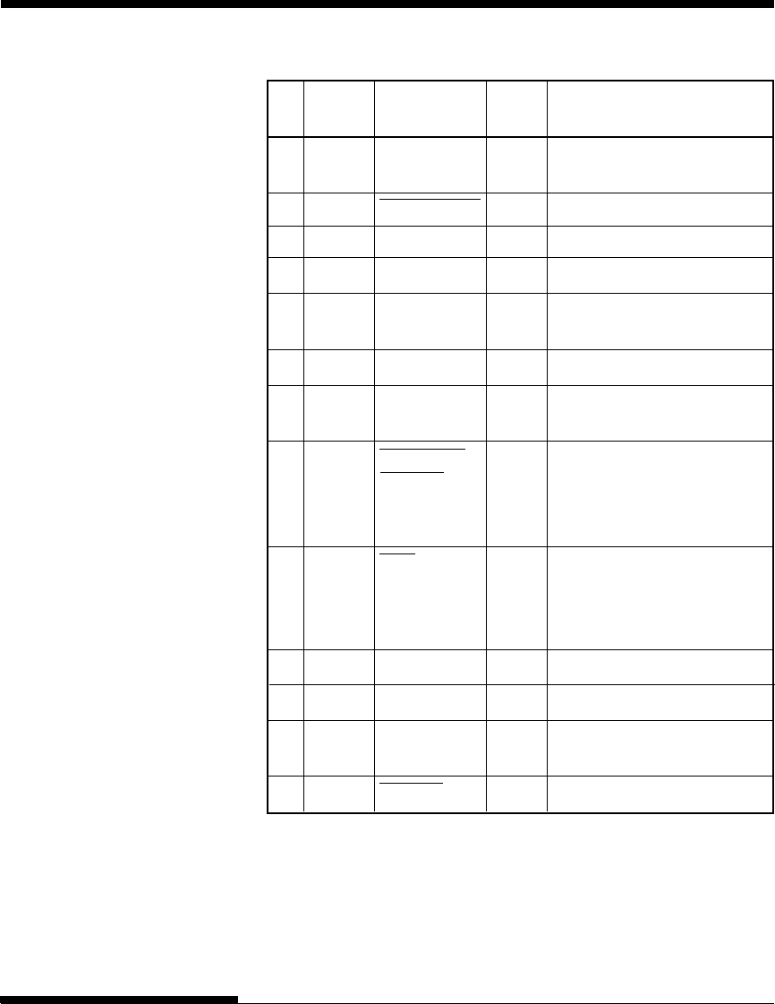
Pin Return Signal Direc- Description
No. Pin No. name tion
1 19 Data Strobe Input This signal is a strobe pulse
(DSTB) for reading data (Data 1 to 8).
The printer reads data when this
signal is low. The pulse width
must be 1 µs or more at the
receiving terminal.
2–9 20--27 Data 1 to 8 Input Data 8 (pin 9) is the most
significant bit; however, this pin
is not used in 7-bit ASCII
communications.
Logical 1 signals must go high at
least 1 µs before the falling edge
of the Data Strobe signal and
must stay high for at least 1 µs
after the rising edge.
10 28 Acknowledge Output This pulse signal indicates
(ACK) that the printer has received data
and is ready to accept the next set
of data.
This signal is also sent when the
printer is switched from offline to
online.
11 29 Busy Output Data cannot be received when
this signal is high. This signal is
high during data entry, when the
printer is offline, when the buffer
is full, or when an error occurs.
12 30 Paper Empty Output This signal is high when the
(PE) printer is out of paper.
Compatible Mode
User's ManualD-4
INTERFACE INFORMATION
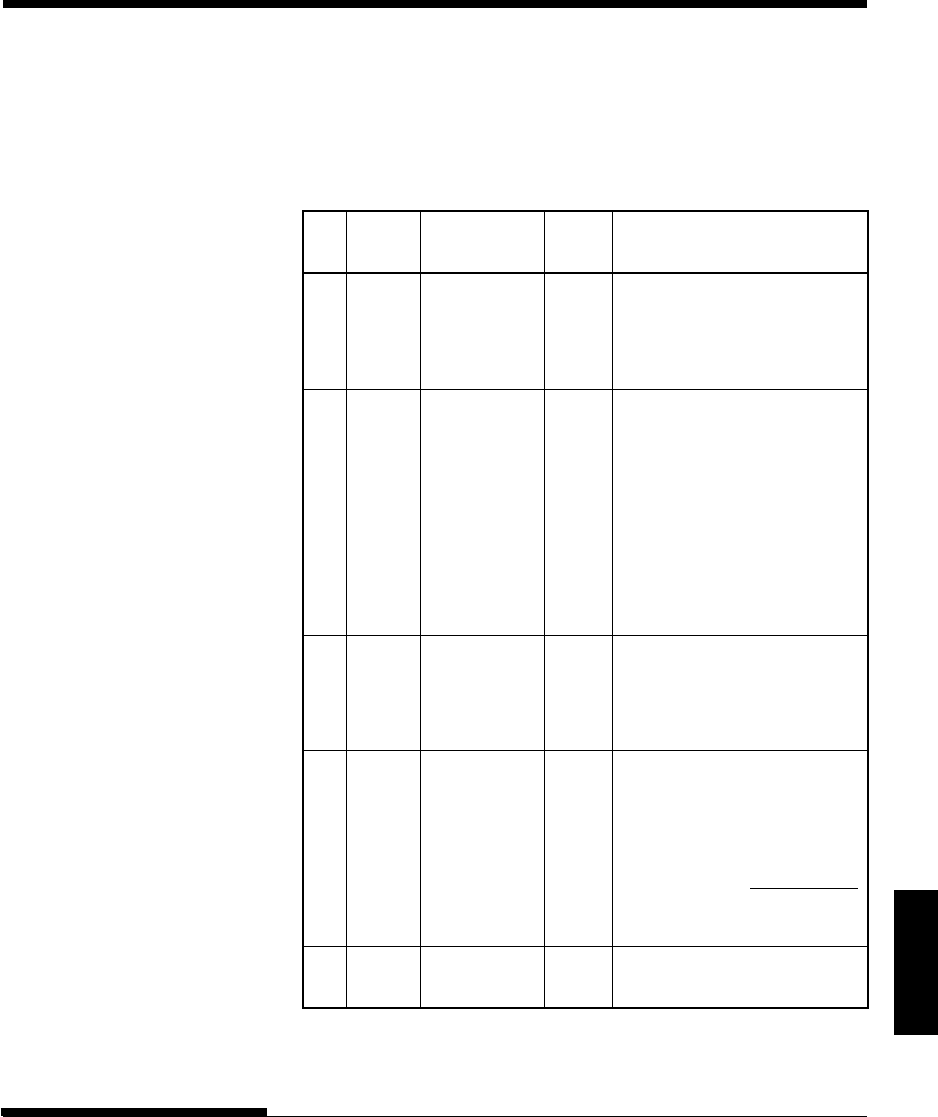
Pin Return Signal Direc- Description
No. Pin No. name tion
13 –Select Output This signal is high when the
(SLCT) printer is online.
14 –Auto Feed XT Input Not used
15 – – –No connection
16 –Signal Ground –Logic ground level (0 V)
17 –Frame Ground –Printer chassis ground line. FG
and SG are connected.
18 –+5V Output +5 V source (up to 300 mA)
19––Signal Ground –Twisted pair return lines
30
31 –Input Prime Input If this signal is low for more
(INPRM) than 50 µs, the printer is reset to
the initial condition and is placed
online.
32 –Fault Output This signal is low when the
printer is offline, paper is out, or
when there is a printer error.
33 –Signal Ground –Logic ground level (0 V)
34 – – –No connection
35 –+5 VR Output Pulled up to +5 V through a
3.3 ký resistor
36 –SLCT-IN Input Not used
Interface
D-5
User's Manual
INTERFACE INFORMATION
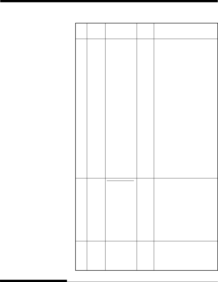
Nibble Mode
Pin numbers 2 to 9, 15 to 31, and 33 to 35 are the same as the conventional
mode.
Pin Return Signal Direc- Description
No. Pin No. name tion
1 19 Host Clock Input This signal is set high when the
host requests the reverse data
transfer phase (nibble mode).
10 28 Printer Clock Output Reverse data transfer phase:
This signal goes high when data
being sent to the host is
established.
Reverse idle phase:
This signal is set low then goes
high to interrupt the host,
indicating that data is available.
11 29 Printer Busy Output Reverse data transfer phase:
Data bit 3, data bit 7, then
forward path (host to printer)
busy status
12 30 Ack Data Req Output Reverse data transfer phase:
Data bit 2, then data bit 6
Reverse idle phase:
This signal is set high until the
host requests data and, after that,
follows the
Data Available
signal.
13 –X Flag Output Reverse data transfer phase:
Data bit 1, then data bit 5
User's ManualD-6
INTERFACE INFORMATION
Pin Return Signal Direc- Description
No. Pin No. name tion
14 –Host Busy Input Reverse data transfer phase:
This signal is set low when the
host can receive data, and goes
high when the host has received
data. Following a reverse data
transfer, the interface enters the
reverse idle phase when the Host
Busy signal goes low and the
printer has no data.
Reverse idle phase:
This signal goes high when the
Printer Clock signal goes low so
that the interface re-enters the
reverse data transfer phase. If it
goes high with the 1284 Active
signal low, the 1284 idle phase is
aborted and the interface returns
to the compatibility mode.
32 –
Data Available
Output Reverse data transfer phase:
This signal is set low when the
printer is ready to send data to
the host. During the data
transfer, it is used as data bit 0
(LSB), then data bit 4.
Reverse idle phase:
This signal is used to indicate
that data is available.
36 –1284 Active Input This signal goes high to cause the
printer to enter the reverse data
transfer phase (nibble mode).
Interface
D-7
User's Manual
INTERFACE INFORMATION
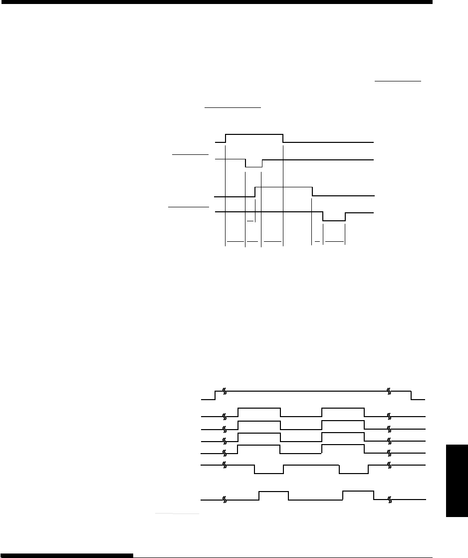
Data Transmission Timing
In unidirectional mode (conventional Centronics interface), this printer
guarantees the received data when the Data and Data Strobe signals from the
computer have the following timing with respect to the Busy and
Acknowledge signals from the printer.
➤
➤
➤
➤
➤
➤
➤
➤
➤
➤
➤
➤
T5 T6
T1, T2, T3 > 1 µs
T4 < 1 µs
0 µs < T5 < 3 µs
2 µs < T6 < 6 µs
T1
Data 1 to Data 8
Data Strobe
BUSY
Acknowledge
T2 T3
T4
In bidirectional mode (nibblemode), this printer can send data to the
computer. Data is sent in units of four bits (nibble) using four output signal
lines as data paths. The following outlines one byte of data sent during
reverse data transfer phase in nibble mode.
Data Available (*)
X Flag
Ack Data Req
Printer Busy
Host Busy
(from CPU)
Printer Clock
Data bit 4
Data bit 5
Data bit 6
Data bit 7
Data bit 0
Data bit 1
Data bit 2
Data bit 3
1284 Active
(from CPU)
* Data Available is assigned for the cable.
User's ManualD-8
INTERFACE INFORMATION
SERIAL INTERFACE RS-232C is the standard serial interface for data terminal equipment. The
cable connector at the printer side should be a D-subminiature Cannon or
Cinch DB-25P male connector or equivalent that conforms to EIA standards.
The table that follows shows the pin assignments commonly used by most
computers. In the table:
•“Input” denotes a signal from the computer to the printer.
•“Output” denotes a signal from the printer to the computer.
•The signal level for mark state (logical 1) is -3 V or lower; for space
state (logical 0), it is +3 V or higher.
Pin Signal Direc- Description
No. Name tion
1FG –Frame Ground
2 TD Output Transmitted Data. This pin carries information
from the printer to the computer.
3 RD Input Received Data. This pin carries information from
the computer to the printer.
4 RTS Output Request To Send. Spaces are sent when the
printer is ready to transmit data.
5 CTS Input Clear To Send. Spaces are sent when the
computer is ready to receive data.
6 DSR Input Data Set Ready. Spaces are sent when the
computer has been powered on and is ready to
receive or transmit data.
7SG –Signal Ground (common return)
8 CD Input Carrier Detect. Spaces are sent when the
computer allows the printer to receive data.
11 RC Output Reverse Channel. This signal is used instead of
the DTR signal in the RC protocol. Spaces are
sent when the printer is ready to receive or
transmit data.
20 DTR Output Data Terminal Ready. Spaces are sent when the
printer has been powered on and is ready to
receive or transmit data.

Interface
D-9
User's Manual
INTERFACE INFORMATION
Serial Options
The serial options for the computer and the printer must match. Use the
printer control panel, the computer operating system, or your software to
change options specified as “selectable.”
Transmission mode: Asynchronous, full duplex, or half duplex
(selectable)
Speed: 150, 300, 600, 1200, 2400, 4800, 9600, or 19200
baud (selectable)
Data bits: 7 or 8 bits (selectable)
Parity bit: Odd, even, mark, space, or none (selectable)
Start bit: 1 bit
Stop bit: 1 or 2 bits (selectable)
Protocol: XON/XOFF (DC1/DC3), DTR (Data Terminal
Ready), or RC (Reverse Channel) (selectable)
Buffer size: 256, 2K, 8K, 24K, 32K, 96K, or 128K bytes
(selectable)
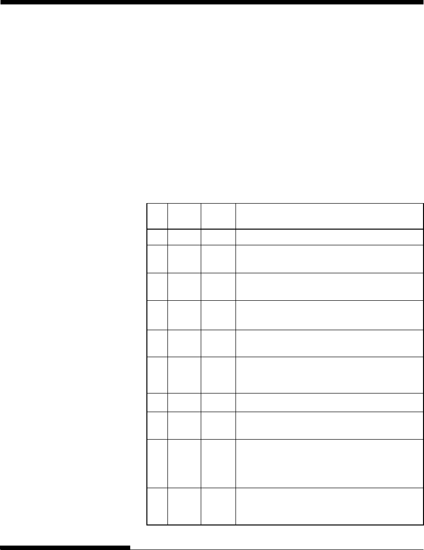
Cable Wiring
This printer allows two types of serial communication control: DSR-enabled
and DSR-disabled. The type of control required is determined by your
computer requirements. The type of control also affects the way the interface
cable is wired. To determine whether you need DSR-enabled control or DSR-
disabled control, use the printer HARDWRE function (see Chapter 5).
DSR-disabled control offers simpler cabling and communication than does
DSR-enabled control. DSR-disabled control can be used to interface with an
IBM PC and most other personal computers. With DSR-disabled control, the
input control signals DSR, CTS, and CD are always considered high,
regardless of their actual states. Therefore, no wire connection for these pins
is required. The following figure shows the wiring required for connection to
an IBM PC.
User's ManualD-10
INTERFACE INFORMATION
TD
RD
DSR
DTR
RTS
CTS
CD
SG
Host Printer
(Pin 2)
(Pin 3)
(Pin 6)
(Pin 20)
(Pin 4)
(Pin 5)
(Pin 8)
(Pin 7)
TD
RD
DSR
DTR (RC)
RTS
CTS
CD
SG
#
#
#
#
#
# indicates an open wire.
Wire q is unnecessary for the DTR (or RC) protocol.
Some computers may not require wire w.
q
w
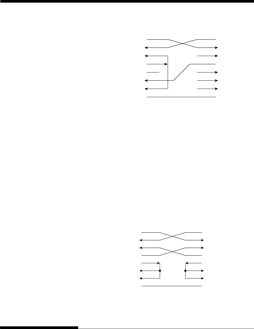
DSR-enabled control enables communication using an RS-232C interface.
The CTS and DSR input control signals are enabled; CD is ignored. DSR
must be high when the printer receives data. If the printer has data to be
transmitted to the computer, the printer transmits the data when both DSR and
CTS are high.
When using DSR-enabled control, use a straight-through cable to connect to a
DCE (data communications equipment) device. Use a null-modem cable to
connect to a DTE (data terminal equipment) device, as shown below.
TD
RD
DSR
DTR
RTS
CTS
CD
SG
Host (DTE) Printer (DTE)
(Pin 2)
(Pin 3)
(Pin 6)
(Pin 20)
(Pin 4)
(Pin 5)
(Pin 8)
(Pin 7)
TD
RD
DSR
DTR
RTS
CTS
CD
SG
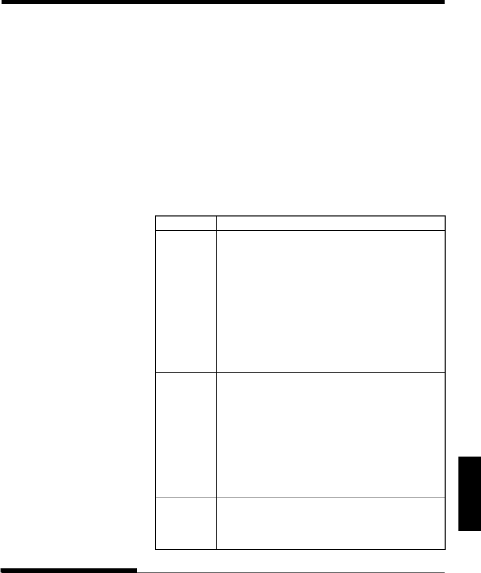
Interface
D-11
User's Manual
INTERFACE INFORMATION
Serial Protocols
A protocol is a set of instructions that control the way data is transmitted
between devices such as a computer and printer. The protocol ensures that
the computer does not send information to the printer faster than the
information can be processed. By telling the computer when the printer can
receive data, the protocol prevents the printer’s buffer from overflowing.
This printer offers a choice of four different protocols for connection to a
variety of computers: XON/XOFF, DTR, and RC. If you computer
documentation does not recommend a particular protocol, try DTR. The
following table describes the three protocols.
Protocol Description
XON/XOFF When the printer is ready to receive data, it sends the
(DC1/DC3) XON (DC1) code (hex 11). When fewer than 255 bytes of
space remain in the buffer (or when the printer is taken
offline), the printer sends the XOFF (DC3) code (hex 13).
(When the input buffer is configured for 256 bytes, the
buffer limit is reduced from 255 bytes to 63 bytes.) The
computer must stop transmitting data within 255 (63)
characters of receiving the XOFF code, or information may
be lost. If paper runs out, the printer sends an NAK code
(hex 15).
DTR DTR is a hardware protocol; that is, the DTR signal on
interface cable pin 20 is used to control the flow of data
rather than transmission of a character code. When the
printer is ready to receive data, pin 20 is high. When fewer
than 255 (63) bytes of space remain in the buffer (or when
the printer is taken offline), pin 20 is low. The computer
must stop transmitting data within 255 (63) characters of
DTR being low, or information may be lost.
RC The RC protocol is the same as the DTR protocol, except
that the Reverse Channel signal (pin 11) is used instead of
the Data Terminal Ready signal (pin 20).

User's ManualD-12
INTERFACE INFORMATION
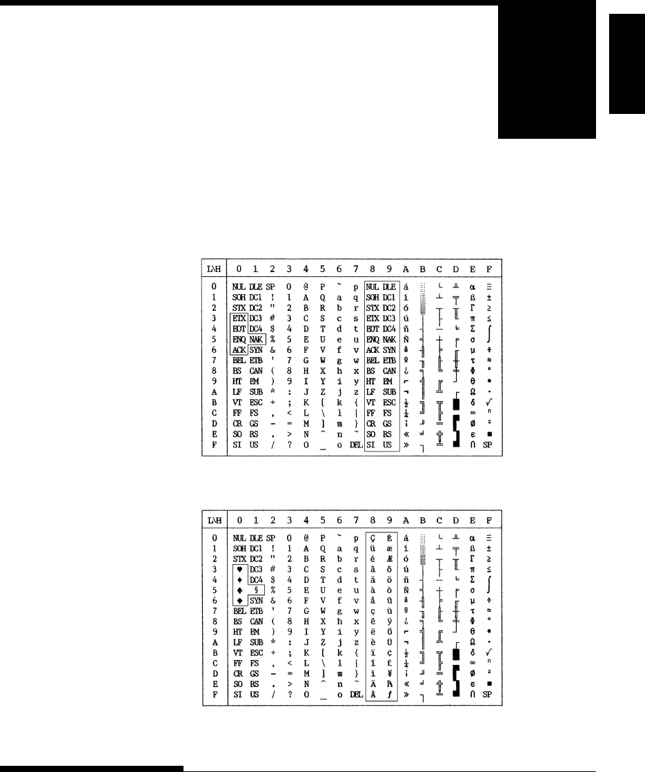
User's Manual E-1
Character
Sets
CHARACTER SETS
CHARACTER SETS
Below are character sets 1 and 2 of Code Page 437,
available in the DPL24C PLUS command set and
the IBM Proprinter XL24E emulation. Characters
enclosed in boxes differ for sets 1 and 2.
Characters in set 2 also vary with the national character set.
Code Page 437 is for the USA character set.
Code Page 437 Character Set 1
CHARACTER SETS 1
AND 2
(DPL24C PLUS AND
IBM XL24E
EMULATION)
E
Code Page 437 Character Set 2
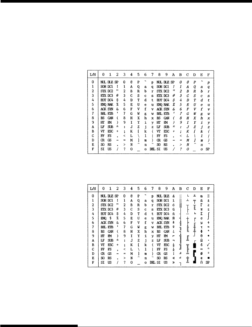
E-2 User's Manual
CHARACTER SETS
The following shows character sets available in the Epson ESC/P2 emulation.
Characters differ in codes 128 to 255 (hex 80 to FF).
Italic Character Set
ITALIC AND GRAPHICS
CHARACTER SETS (ESC/
P2 EMULATION)
Graphics Character Set 1
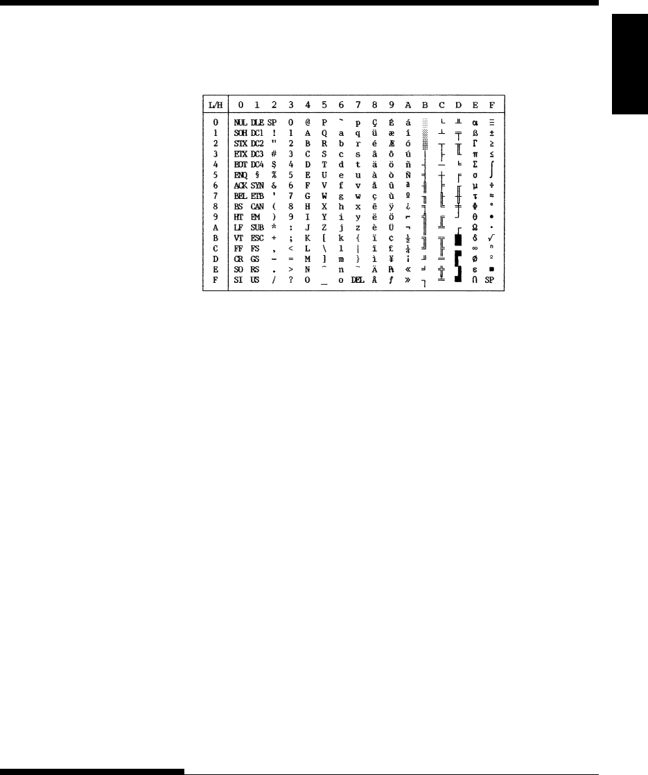
User's Manual E-3
Character
Sets
CHARACTER SETS
Graphics Character Set 2
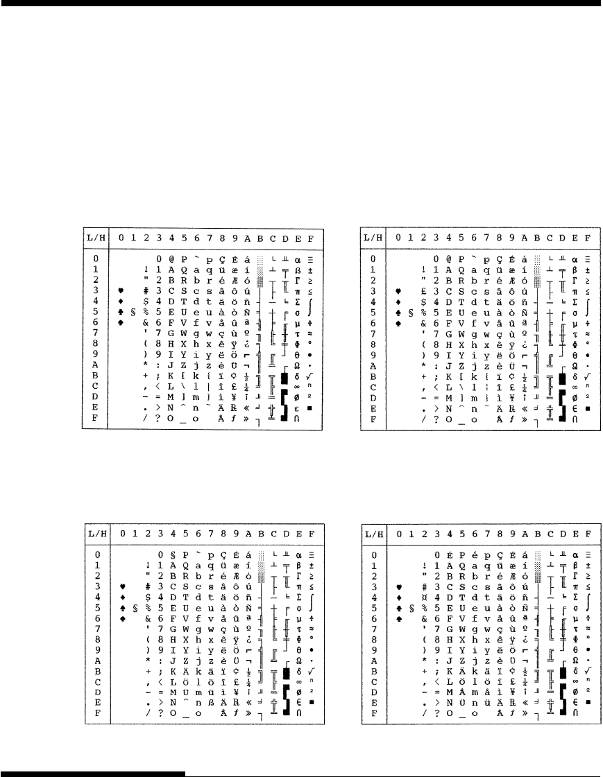
E-4 User's Manual
CHARACTER SETS
Below are the 50 national character sets available for all emulations of this
printer. These character sets support different characters and symbols specific
to different languages. Note that these tables are for Courier 10, a resident
font, and that some national character sets do not have some characters and
symbols whose use depends on resident fonts. For details, see the table at the
end of this appendix.
NATIONAL CHARACTER
SETS (ALL
EMULATIONS)
PAGE437/USA (Code Page 437/USA) UK (British English)
GERMAN (German) SWEDISH (Swedish)
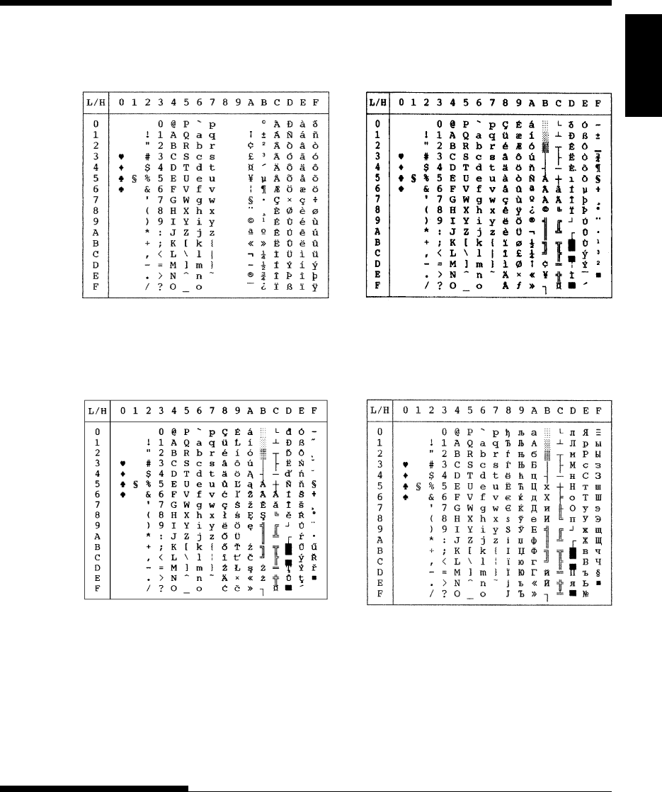
User's Manual E-5
Character
Sets
CHARACTER SETS
ISO8859/ECMA94 (ISO 8859-1/ECMA94)
PAGE850 (Code Page 850(Multilingual))
PAGE852/PG852-T (Code Page 852) PAGE855 (Code Page 855)
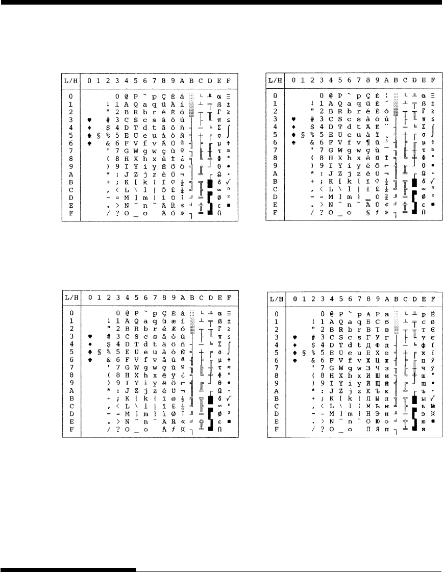
E-6 User's Manual
CHARACTER SETS
PAGE865 (Code Page 865(Nordic)) PAGE866 (Code Page 866(Cyrillic))
PAGE860 (Code Page 860(Portugal))
PAGE863 (Code Page 863 (Canada-French))
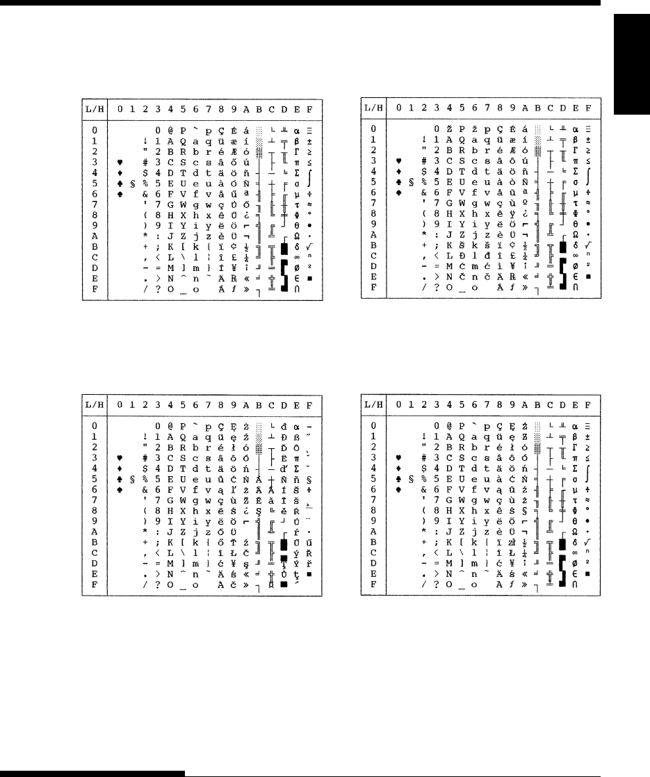
User's Manual E-7
Character
Sets
CHARACTER SETS
HUNGARY/HUNG-T (Hungarian) SLOV/SLOV-T (Slovenian)
POLISH/POLSH-T (Polish) MAZOWIA/MAZOW-T (Mazowian)
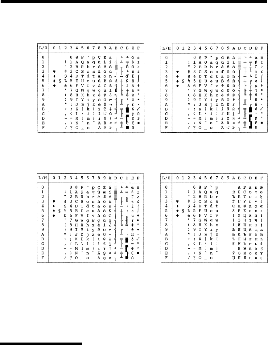
E-8 User's Manual
CHARACTER SETS
TURKY/TURKY-T (Turkish) CYRILIC (Cyrillic)
LATIN2/LATN2-T (Latin2) KAMENIC/KAMEN-T (Kamenicky)

User's Manual E-9
Character
Sets
CHARACTER SETS
IBM437 (IBM 437) IBM851 (IBM 851)
ELOT928 (ELOT 928) PG-DHN (Code Page DHN)
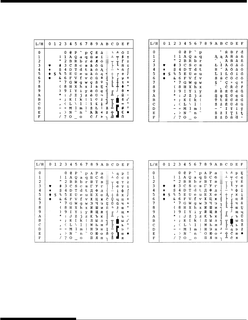
E-10 User's Manual
CHARACTER SETS
LATIN-P (Latin Polish) ISO-LTN (ISO Latin)
LITHUA1 (Lithuanian 1) LITHUA2 (Lithuanian 2)
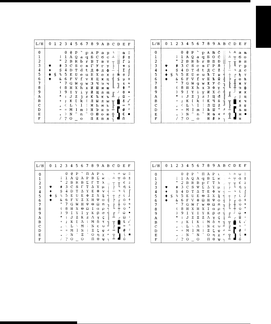
User's Manual E-11
Character
Sets
CHARACTER SETS
MIK MACEDON (Macedonian)
ABG ABY
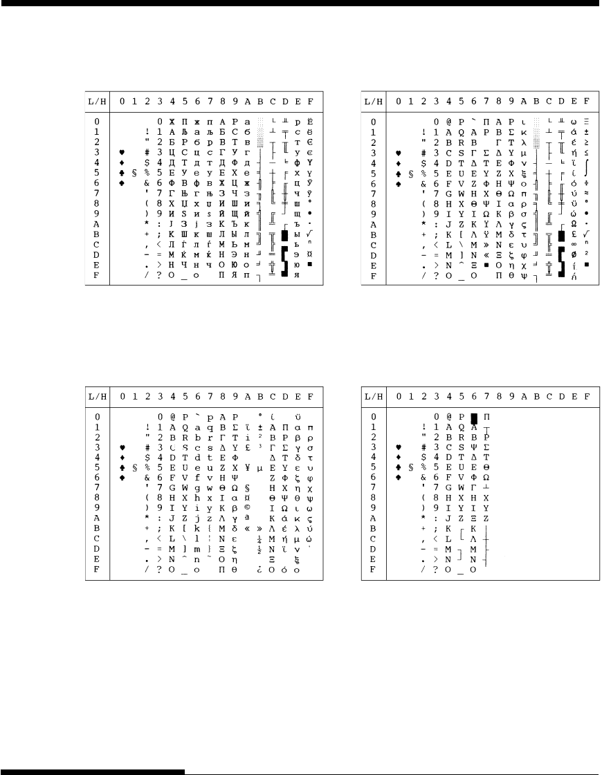
E-12 User's Manual
CHARACTER SETS
DECGR GREEK 11
PG-MAC ELOT927
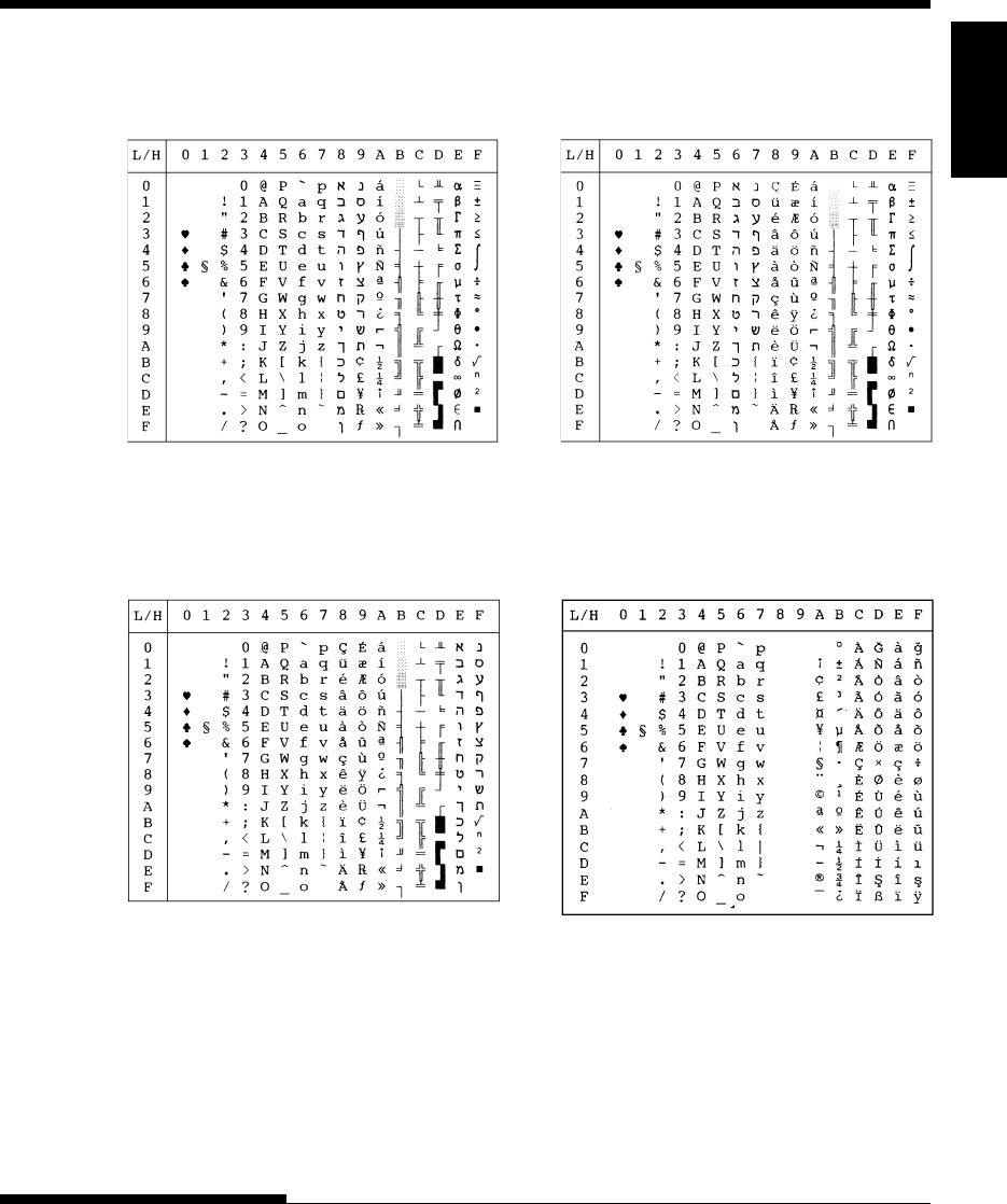
User's Manual E-13
Character
Sets
CHARACTER SETS
PAGE862 HBR OLD
HBR DEC ISO-TUK
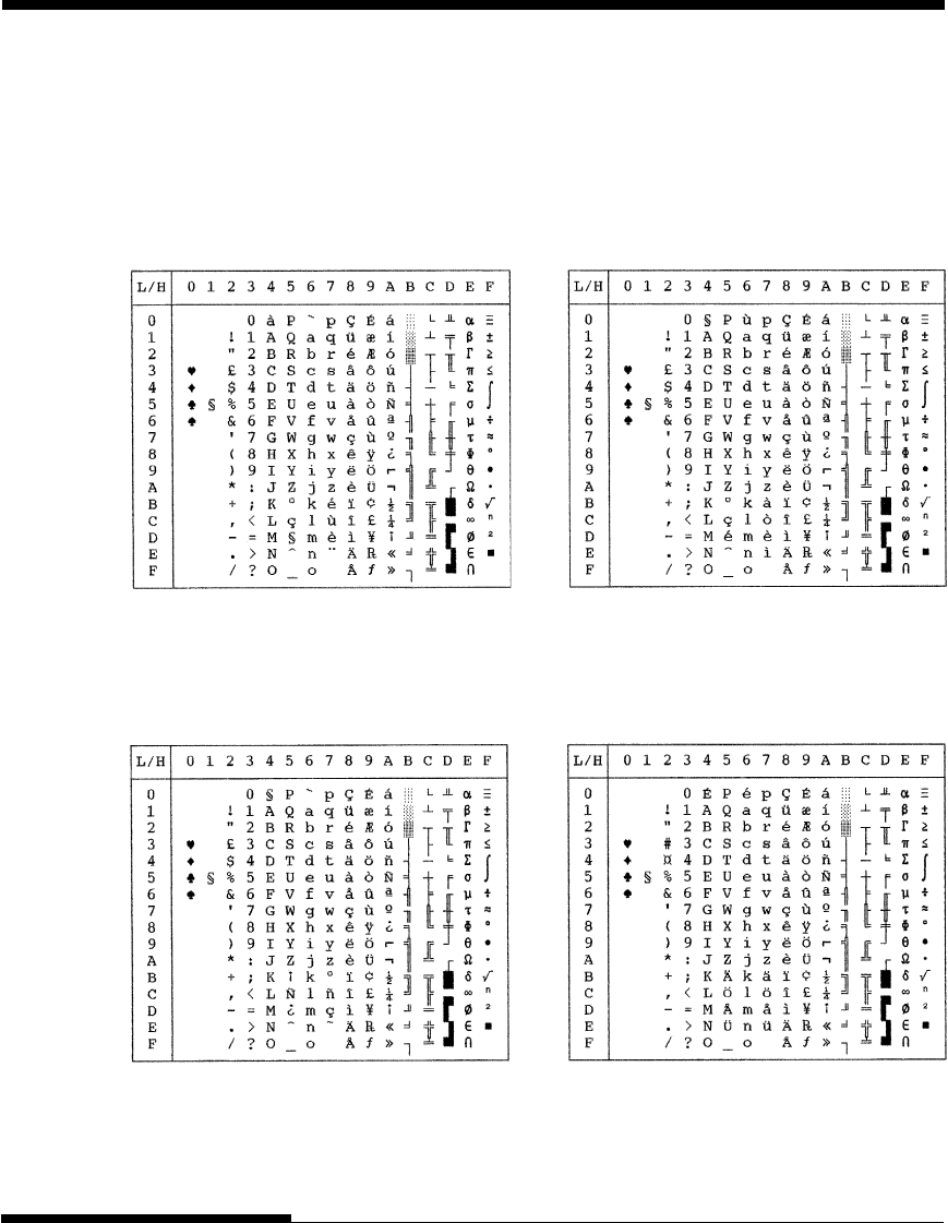
E-14 User's Manual
CHARACTER SETS
The following character sets differ from those of Code Page 437 (USA),
available in the DPL24C PLUS command set and the IBM Proprinter XL24E
emulation.
NATIONAL CHARACTER
SETS (DPL24C PLUS AND
IBM XL24E EMULATION)
FRENCH (French) ITALIAN (Italian)
SPANISH (Spanish) FINNISH (Finnish)
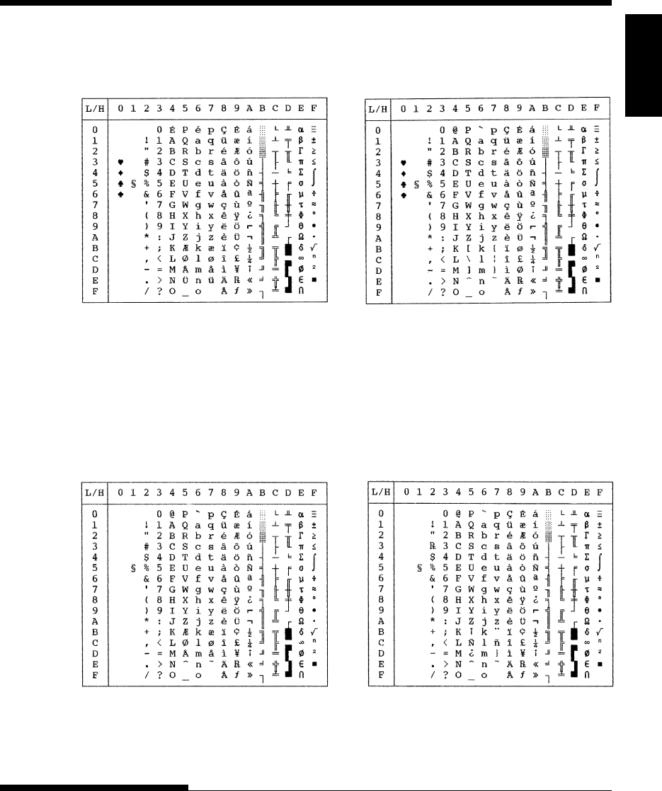
User's Manual E-15
Character
Sets
CHARACTER SETS
DANISH1/NORWEGN (Danish1/Norwegian)
DANISH2 (Danish2)
NATIONAL CHARACTER
SETS (ESC/P2 EMULATION)
The following character sets differ from the graphics character sets available in
the Epson ESC/P2 emulation.
DANISH1 (Danish1) SPANSH1 (Spanish1)
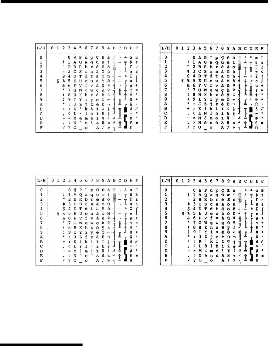
E-16 User's Manual
CHARACTER SETS
ITALIAN (Italian) SPANSH2 (Spanish2)
JAPAN (Japanese) LATIN A (Latin American)

User's Manual E-17
Character
Sets
CHARACTER SETS
NORWEGN (Norwegian) FRENCH (French)
DANISH2 (Danish2) KOREA (Korea)
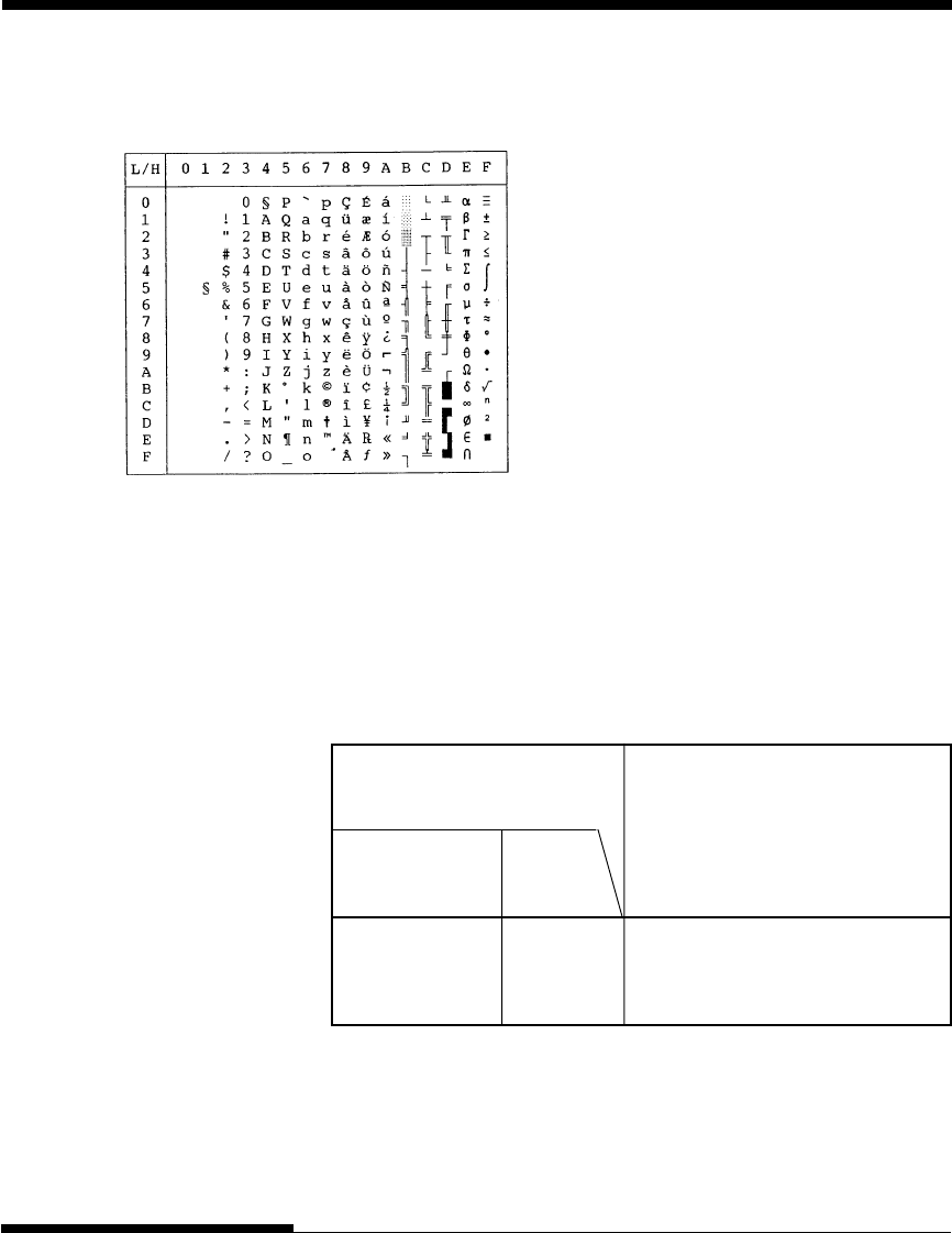
E-18 User's Manual
CHARACTER SETS
(Continued on the next page)
* USA is the same as Code Page 437.
** These are scalable and provided with upright, italic, and bold as resident
fonts.
*** H-draft stands for high-speed draft.
√: Supported
LEGAL (Legal)
In all emulations, this printer supports 50 national character sets for
characters and symbols specific to different languages. Some national
character sets, however, do not have some characters and symbols and may
not be usable, depending on resident fonts. The following tables show which
of the resident fonts are supported for each national character set:
NATIONAL CHARACTER
SETS AND SUPPORTED
RESIDENT FONTS (ALL
EMULATIONS)
USA * USA √√√√√√√√√√√√
United Kingdom UK √√√√√√√√√√√
German GERMAN √√√√√√√√√√√
Resident font
National
character set
Name in
setup menu
OCR-A
OCR-B
H-draft***
Correspondence
Nimbus Sans **
Timeless **
Courier scalable**
Pica 10
Bold PS
Draft
Compress
Elite 12
Courier 10
User's Manual E-19
Character
Sets
CHARACTER SETS
Swedish SWEDISH √√√√√√√√√√√√
ISO 8859-1 ISO8859 √√√√√√√√√√√√
ECMA94 ECMA94 √√√√√√√√√√√√
Code Öage 437 * ÖAGE437 √√√√√√√√√√√√√
Code Öage 850 ÖAGE850 √√√√√√√√√√√√
Code Öage 852 ÖAGE852 √√√√√√√√√√√
Code two-Öass ÖAGE852-T √√√√√√√√√√√
Code Öage 855 ÖAGE855 √√√√ √√√
Code Öage 860 ÖAGE860 √√√√√√√√√√√√
Code Öage 863 ÖAGE863 √√√√√√√√√√√√
Code Öage 865 ÖAGE865 √√√√√√√√√√√√
Code Öage 866 ÖAGE866 √√√√ √√√
Hungarian HUNGARY √√√√√√√√√√√
Hungarian HUNG-T √√ √√√√√√ √√√
two-Öass
Slovenian SLOV √√ √√√√√√ √√√√
Slovenian SLOV-T √√ √√√√√√ √√√
two-Öass
Öolish ÖOLISH √√ √√√√√√ √√√
Öolish two-Öass ÖOLSH-T √√ √√√√√√ √√√
Mazovian MAZOWIA √√ √√√√ √√
Mazovian MAZOW-T √√ √√√√ √√
two-Öass
Latin 2 LATIN2 √√ √√√√√√ √√√
Latin 2 two-Öass LATIN2-T √√ √√√√√√ √√√
Resident font
National
character set
Name in
setup menu
OCR-A
OCR-B
H-draft***
Correspondence
Nimbus Sans **
Timeless **
Courier scalable**
Pica 10
Bold PS
Draft
Compress
Elite 12
Courier 10
(Continued on the next page)
* USA is the same as Code Page 437.
** These are scalable and provided with upright, italic, and bold as resident
fonts.
*** H-draft stands for high-speed draft.
√: Supported
E-20 User's Manual
CHARACTER SETS
Kamenicky KAMENIC √√ √√√√√√ √√√
Kamenicky KAMEN-T √√ √√√√√√ √√√
two-Öass
Turkish TURKY √√ √√√√√√ √√√
Turkish two-Öass TURKY-T √√ √√√√√√ √√√
Cyrillic CYRILIC √√ √ √ √√ √
IBM 437 IBM437 √√ √ √ √√ √ √
IBM 851 IBM851 √√ √ √ √√ √ √
ELOT 928 ELOT928 √√ √ √ √
Code Öage DHN ÖG-DHN √√ √√√√ √√
Latin Öolish LATIN-Ö√√ √√√√ √√
ISO Latin ISO-LTN √√ √√√√ √√
Lithuanian 1 LITHUA1 √√ √ √
Lithuanian 2 LITHUA2 √√ √ √
MIK MIK √√ √ √ √√ √
Macedonian MACEDON √√ √ √ √√ √
ABG ABG √√ √ √ √√ √
ABY ABY √√ √ √ √√ √
Code Öage MAC ÖG-MAC √√ √ √ √√ √
ELOT927 ELOT927 √√ √ √ √√ √
DEC Greek DEC GR √√ √ √ √√ √
Greek 11 GREEK 11 √√ √ √ √√ √
Code Öage 862 ÖG862 √√ √√√√
Hebrew Old HBR-OLD √√ √√√√
Hebrew DEC HBR-DEC √√ √√√√
ISO-Turkish ISO-TUK √√ √√√√
RUSCII
LATIN-9
Resident font
National
character set
Name in
setup menu
OCR-A
OCR-B
H-draft***
Correspondence
Nimbus Sans **
Timeless **
Courier scalable**
Pica 10
Bold PS
Draft
Compress
Elite 12
Courier 10
* USA is the same as Code Page 437.
** These are scalable and provided with upright, italic, and bold as resident
fonts.
*** H-draft stands for high-speed draft.
√: Supported
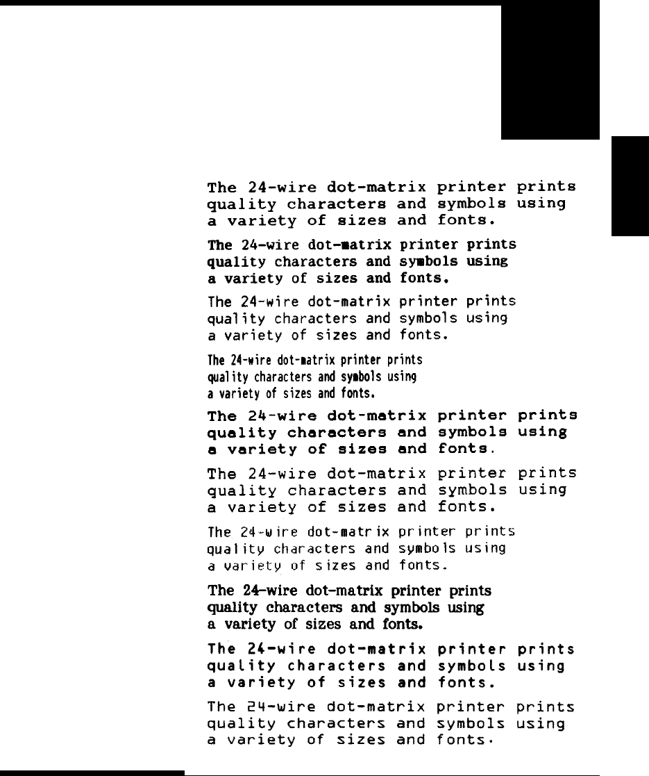
User's Manual F-1
Fonts
RESIDENT FONTS
RESIDENT FONTS
This appendix provides print samples of
the printer's nineteen resident fonts.
COURIER 10
DRAFT 12
F
PRESTIGE ELITE 12
COMPRESSED
PICA 10
CORRESPONDENCE 10
HIGH-SPEED DRAFT 12
BOLDFACE PS
OCR-B 10
OCR-A 10
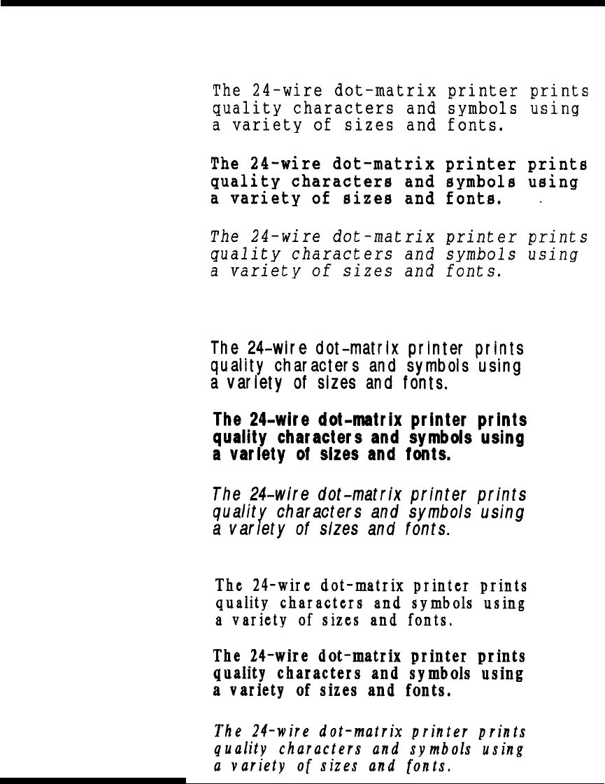
F-2 User's Manual
RESIDENT FONTS
COURIER (SCALABLE)
Normal
Bold
Italic
NIMBUS SANS ®
(SCALABLE)
Normal
Bold
Italic
TIMELESS (SCALABLE)
Normal
Bold
Italic

User's Manual GL-1
Glossary
GLOSSARY OF TERMS
GLOSSARY OF TERMS
A standard paper size used in Japan and other countries. Paper is 210
¥ 295 mm (8.25 ¥ 11.6 inches).
Software programs that perform tasks on a computer. Such programs
include word processing, database management, and accounting, for
example.
The acronym for American National Standard Code for Information
Interchange. ASCII is a set of 256 codes (numbered 0 to 255) used to
communicate information between a computer and another device
such as a printer.
The speed, in bits per second, at which data is transmitted to a device
such as a printer. Baud rates apply to serial data only. 1200 baud
equals approximately 120 characters per second.
Alternate printing of lines from left to right and right to left.
Bidirectional printing is faster than unidirectional printing because
there are no carriage returns.
The smallest unit of information in computer memory. A bit is a
single digit, either a 1 or a 0, in the binary numbering system. Eight
bits equal one byte.
A storage area for data in the printer or computer. The printer’s
buffer consists of a print buffer and a download buffer. The print
buffer holds data to be printed. The download buffer holds
downloaded data such as download (soft) fonts.
A byte consists of eight bits that constitute one symbol. A byte
represents a single character, such as number, letter, or special
control character.
A4 size
Application software
ASCII
Baud rate
Bidirectional printing
Bit
Buffer
Byte

GL-2 User's Manual
GLOSSARY OF TERMS
The return of the print head carriage to the beginning of the next line.
A type of parallel interface. See Parallel interface.
A vertical section on a printed page. This printer can print 80-column
pages at 10-pitch (10 characters per inch).
A set of print and format commands used to control the printer. Each
printer has its own resident command sets embedded in the printer
firmware. These command sets are actuated by codes sent from the
host computer.
Print that uses “condensed” characters. Condensed characters are
narrower than regular characters. Using condensed print increases the
number of characters per line.
Connected, fan-folded sheets of paper that are fed into the printer
using forms tractors. The fan-folded sheets are separated by tearing
them at their perforations.
A panel containing the printer indicators and buttons. The control
panel is used to control printer operations, such as loading paper,
selecting print features, and changing setup options.
Characters per horizontal inch. Also referred to as pitch. For
example, 12-pitch means 12 cpi.
Characters per second.
See Single sheets.
Settings selected automatically by the printer when power is turned
on. Enter setup mode to change the defaults to ensure compatibility
with your system hardware and software.
The grid used to print characters on a dot matrix printer. Each dot
corresponds to a wire in the print head.
Carriage return (CR)
Centronics interface
Column
Command set
Condensed print
Continuous forms
Control panel
cpi
cps
Cut sheets
Defaults
Dot matrix

User's Manual GL-3
Glossary
GLOSSARY OF TERMS
Transferring soft fonts from the computer to the printer’s memory.
Downloading allows you to use fonts not resident in the computer.
Dots per inch.
A command set that allows one printer to print like another printer.
This printer has three resident emulations: Fujitsu DPL24C PLUS
(native command set), IBM proprinter XL24E, and Epson ESC/P2.
A complete set of printable characters having the same size and style.
For example, Courier 10 and Prestige Elite 12 are commonly used
fonts.
A signal to the printer to advance the paper forward one page. Form
feeds can be executed either by your software or by holding down the
LF/FF button on the printer control panel.
Controlling the print head wires (dots) individually to produce a
picture or an image on the page.
A base-16 numbering system (also commonly referred to as hex
numbers). Since a base-16 system requires 16 digits, numbers 0
through 9 and letters A through F are used. Expressing binary
numbers in hexadecimal uses fewer digits.
A hexadecimal printout of control codes and data. Hex dumps are
used to debug computer programs and to troubleshoot printer
malfunctions. To print a hex dump on the printer, use the HEX-
DUMP function in setup mode.
A connection that allows communication from one part of a system to
another. For example, electrical signals are transferred between the
computer and printer over an interface cable.
Kilobyte. 1K byte equals 1024 bytes.
Downloading
dpi
Emulation
Font
Form feed (FF)
Graphics printing
Hexadecimal
Hex dump
Interface
K byte

GL-4 User's Manual
GLOSSARY OF TERMS
A standard paper size used in the United States and other countries.
Paper is 8-1/2 ¥ 11 inches (215.9 ¥ 279.4 mm).
A signal to the printer that advances the paper forward one line. Line
feeds can be executed either by your software or by pressing the LF/
FF button on the printer control panel.
The vertical spacing between lines, measured in lines per inch.
Lines per inch. Used to measure line spacing.
Character spacing in which each printed character has the same width.
Also called fixed pitch, monospacing is the opposite of proportional
spacing. Typewriter or computer-printed text is typically
monospaced.
Fonts not present (resident) in the printer’s permanent memory. Soft
fonts and fonts on font cards are examples of nonresident fonts.
One of the printer’s two operating modes. In normal mode, the
control panel can be used to perform everyday printer operations,
such as loading and unloading paper, feeding paper, and selecting
print features. See also Setup mode.
When the printer is offline, it receives commands from the printer
control panel rather than from the computer. “Offline” indicates that
the printer is not “online” with the computer.
When the printer is online, it is ready to receive or is receiving
commands from the computer. The printer must be online to print.
A standard computer interface. Information is transferred between
devices over separate wires, allowing all of the bits that make up the
character to be transmitted simultaneously (in parallel).
The position in which continuous forms paper is retracted or “parked”
on the rear forms tractors. When continuous forms paper is loaded, it
moves forward from the park position to the platen.
Letter size
Line feed (LF)
Line spacing
lpi
Monospacing
Nonresident font
Normal mode
Offline
Online
Parallel interface
Park position

User's Manual GL-5
Glossary
GLOSSARY OF TERMS
Memory that retains information even when power is turned off. The
printer’s permanent memory retains the default settings specified
using the printer setup mode.
Characters per horizontal inch (cpi).
A hard rubber cylinder that moves paper forward during printing.
Character spacing in which wide characters occupy more space than
do narrow characters. For example, characters such as “W” or
“M”occupy more horizontal space than do characters such as “i” or
“l.” Many soft fonts are proportionally spaced. Sometimes
designated PS, proportional spacing is the opposite of monospacing.
A set of instructions that control how data is transmitted between
devices such as a computer and printer.
In rear feed, paper is fed from the rear of the printer. The forms
tractor unit pushes paper into the printer.
Fonts present (resident) in the printer’s permanent memory. For this
printer, the resident fonts are Courier 10, Prestige Elite 12, Pica 10,
OCR-B 10, OSR-A 10, Boldface PS, Compressed font,
Correspondence, Draft, and High-speed Draft. Unlike soft fonts,
resident fonts can always be accessed.
A type of serial interface. See Serial interface.
A test that determines whether the printer is working correctly. Test
pages are printed to show print quality and verify whether all
characters print. The self-test only tests the printer. It does not test
how thecomputer works with the printer.
A standard computer interface. Information is transferred between
devices over a single wire (although other wires are used for control).
A serial interface can use an interface cable greater than 3 meters (10
feet). A long cable is often necessary in networking environments,
where the printer may be shared.
Permanent memory
Pitch
Platen
Proportional spacing
Protocol
Rear feed
Resident fonts
RS-232C interface
Self-test
Serial interface

GL-6 User's Manual
GLOSSARY OF TERMS
One of the printer’s two operating modes. In setup mode, the
controlpanel can be used to select the printer default settings, such as
print features, hardware options, and top-of-form. Setup mode also
provides some diagnostic functions. See also Normal mode.
Shadow printing prints characters twice for emphasis. Characters
printed the second time are shifted slightly to the right.
Single sheets are sheets of paper, envelopes, and noncontinuous
multipart forms fed into the printer using the cut sheet stand or
optional cut sheet feeder. Single sheets are also called cut sheets.
Fonts downloaded from a disk to the printer memory. Soft fonts are
also referred to as downloaded fonts. Unlike resident fonts, soft fonts
are available only when in the printer memory.
Programs that control the computer and printer to perform specified
tasks, such as word processing, database management, and
preparation of spreadsheets. Software is sometimes referred to as
application software.
The total space at the top of the printed page. The top margin is the
sum of the top-of-form setting, the software-specified top margin, and
the printer’s TOP-MRG setting.
The logical top of the physical page, as “understood” by the printer
when loading paper. The default TOF settings are 1 inch (25.4 mm)
for both cut sheets and continuous forms.
A method for feeding continuous forms forward for printing. Holes
on the sides of the forms fit over sprockets on two tractors located
inside the printer. The forms are pulled for bottom feeding and
pushed for rear feeding.
Setup mode
Shadow printing
Single sheets
Soft fonts
Software
Top margin
Top-of-form (TOF)
Tractor feed

User's Manual GL-7
Glossary
GLOSSARY OF TERMS
Unidirectional printing
USB interface
Printing is performed in one direction only, left to right.
Unidirectional printing is slower than bidirectional printing, but
the vertical alignment is more accurate. Unidirectional printing is
useful when precise vertical alignment is required, as in ruled
tables.
A serial bus standard. An abbreviation of Universal Serial
Bus.HotSwap using Plug&Play is available. The maximum
cable length is five meters.
The transmission mode is 12 Mbps + 0.25% at full speed.

GL-8 User's Manual
GLOSSARY OF TERMS
FUJITSU OFFICES Please send your comments on this manual or on Fujitsu products to the
following addresses (arranged alphabetically):
North American Contact:
FUJITSU CANADA INC.
6975 Creditveiw Road, Unit 1,
Mississauga,
Ontario L5N 8E9 2800, CANADA
Phone: (1-905) 286-9666
Fax : (1-905) 286-5977
European Contact:
FUJITSU EUROPE LTD.
Hayes Park Central,
Hayes End Road,
Hayes,
Middlesex UB4 8FE, U.K.
Phone:(44-20)8573-4444
Fax:(44-20)8573-2643
FUJITSU DEUTSCHLAND GmbH
Frankfurter Ring 211,
80807 Munchen, Germany
Phone:(49-89)32-378-0
Fax:(49-89)32-378-100
FUJITSU ITALIA S.p.A.
Via Nazario Sauro, 38
20099 Sesto S. Giovanni (MI), Italy
Phone: (39-02)26294-1,
Fax: (39-02)26294-201
FUJITSU ESPANA, S.A.
Camino Cerro de los Gamos, 1-28224
Pozuelo de Alarcon, Madrid, Spain
Phone: (34-91)784-9000,
Fax: (34-91)784-9266
Australian Contact:
FUJITSU AUSTRALIA LTD.
Fujitsu House 2 Julius Avenue
North Ryde N.S.W. 2113, Australia
Phone:(61-2)9776-4555
Fax:(61-2)9776-4556
Asian Contact:
FUJITSU HONG KONG LTD.
10F., Lincoln House, 979 King's Road, Taikoo
Place,
Island East, Hong Kong
Phone:(852) 2827-5780
Fax:(852) 2827-4724
FUJITSU TAIWAN LTD.
19th FL., No. 39, 1 Sec. Chung Hwa Rd.,
Taipei, Taiwan R.O.C.
Phone: (886-2)2311-2255
Fax : (886-2)2311-2277
FUJITSU SYSTEMS BUSINESS (THAILAND) LTD.
12th Fl., Olympia Thai Tower, 444 Rachadapisek
Road,
Samsennok Huay Kwang, Bangkok 10320,
Thailand
Phone: (66-2)500-1500
Fax : (66-2)500-1515
FUJITSU ASIA PTE. LTD.
20 Science Park Road #03-01, Tele Tech Park II
Singapore 117674
Phone: (65)6777-6577
Fax : (65)6771-5502
FUJITSU PHILIPPINES, INC.
2nd Fl., United Life Bldg., A.Arnaiz,
Legaspi Village, Makati, Metro Manila, Philippines
Phone: (63-2) 812-4001
Fax : (63-2) 817-7576

C147-E046-01EN