Fujitsu Isotec 015M33324A Dot Matrix Printer User Manual FUJITSU DL7400
Fujitsu Isotec Limited Dot Matrix Printer FUJITSU DL7400
UserManual.wiki
>
Fujitsu Isotec
>
015M33324A User Manual
>
Users Manual 3
Contents
1.
Users Manual 1
2.
Users Manual 2
3.
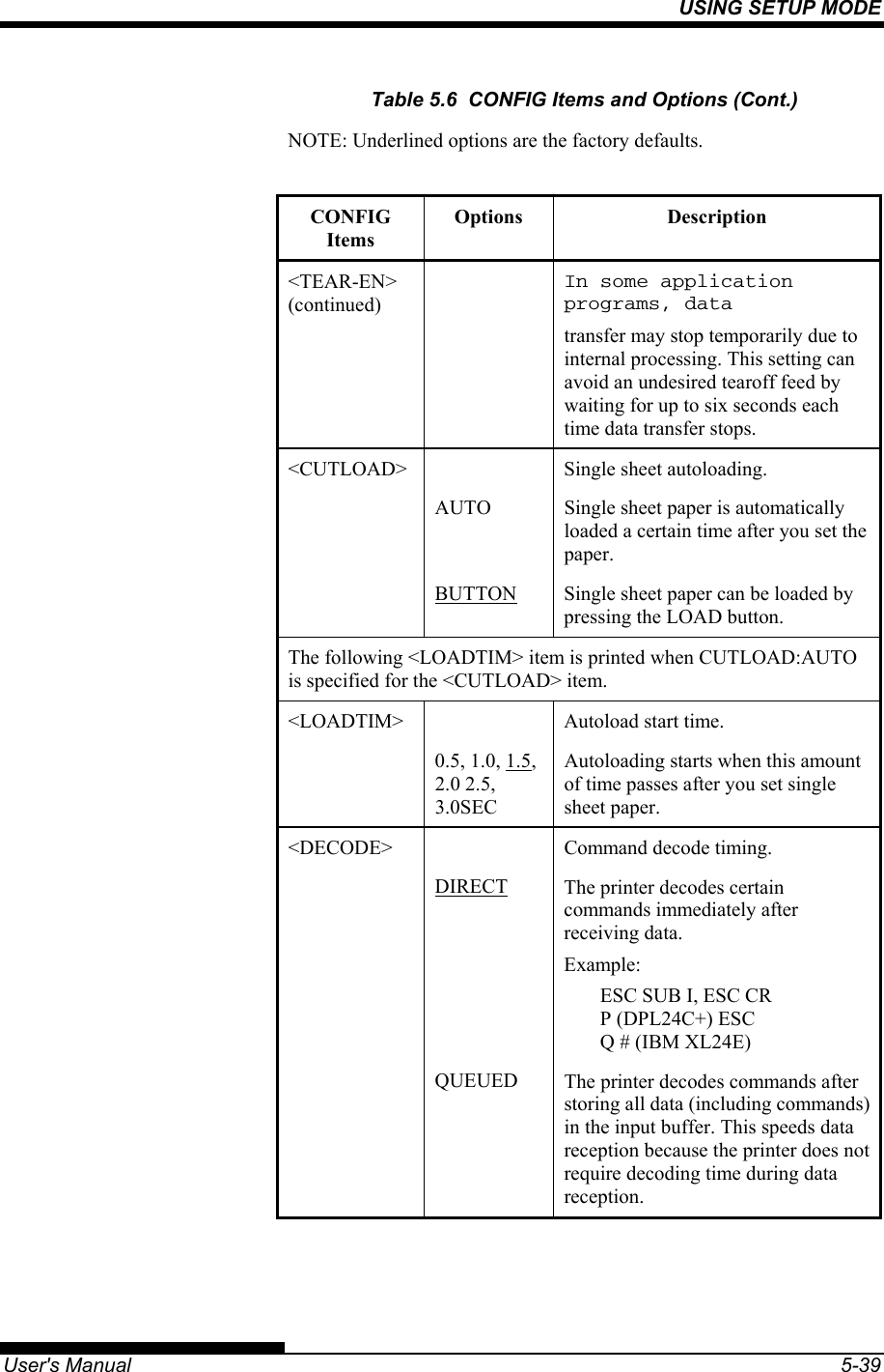
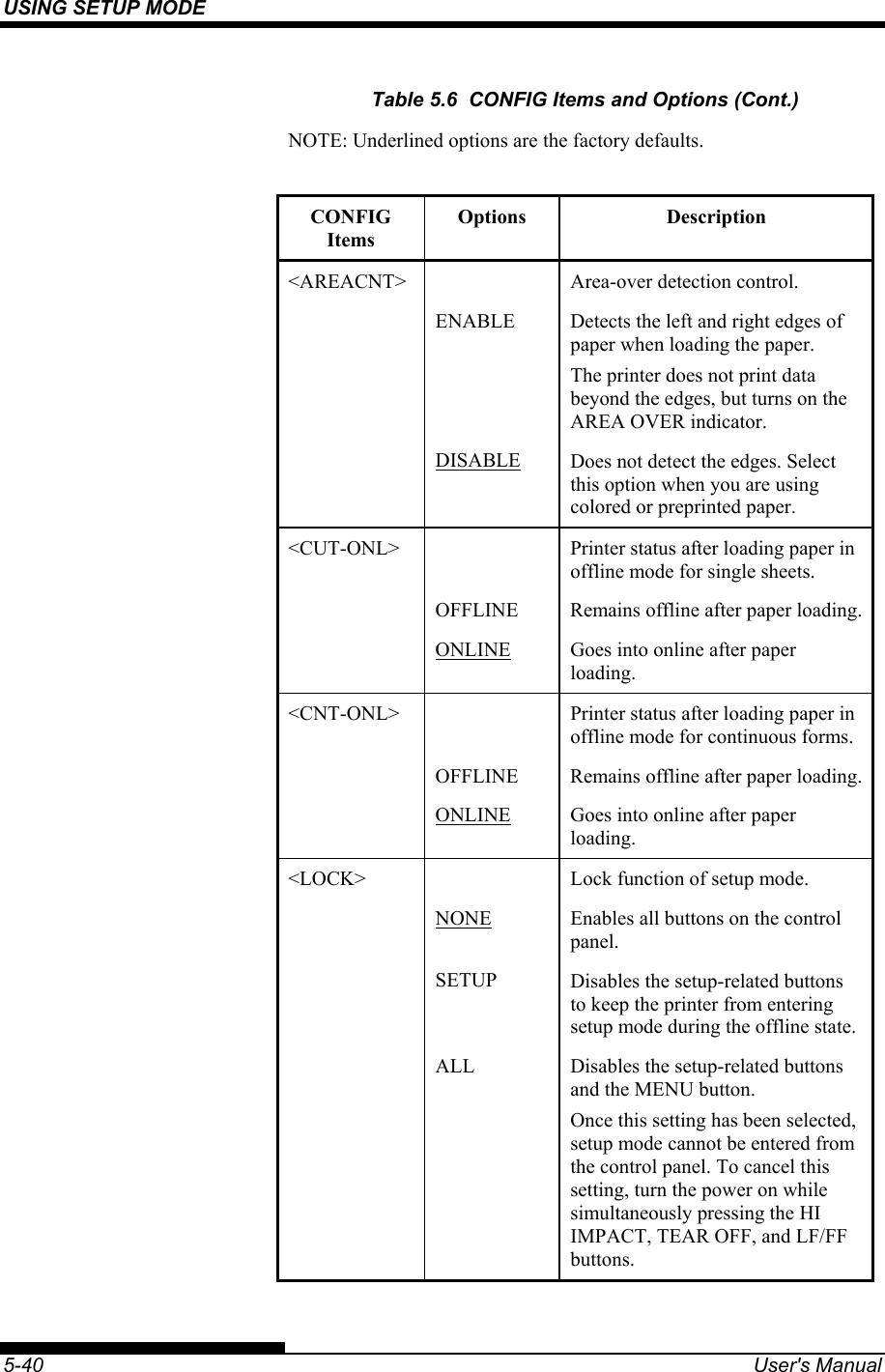
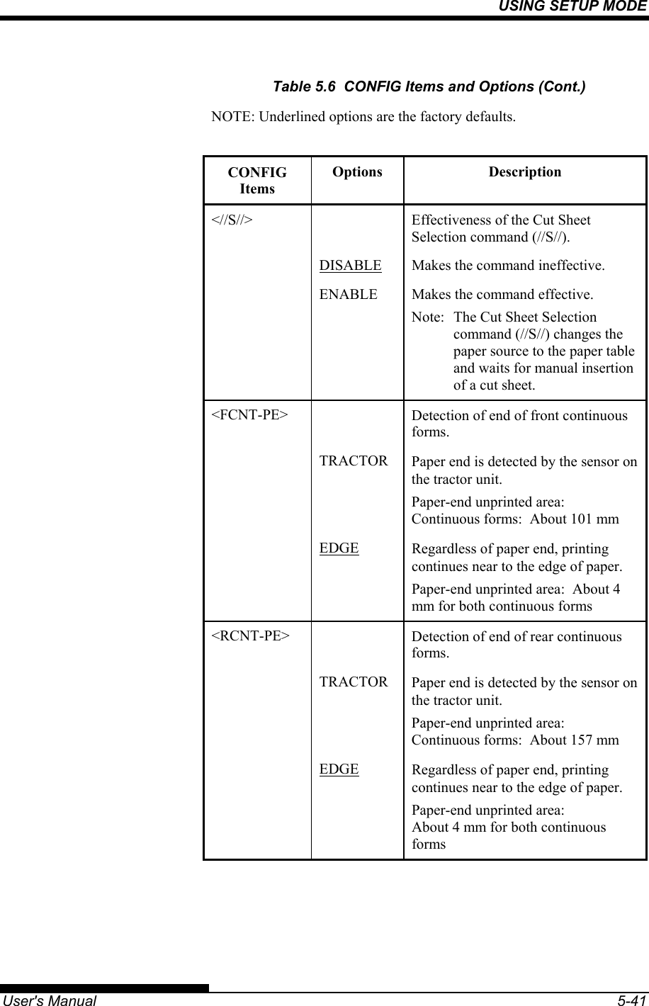
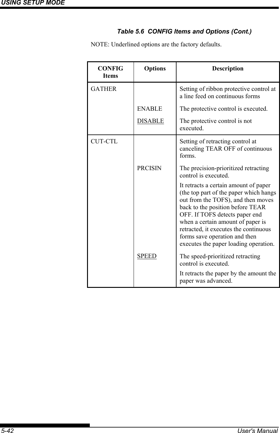
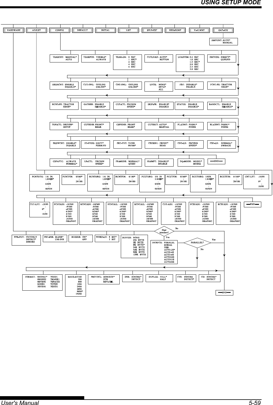
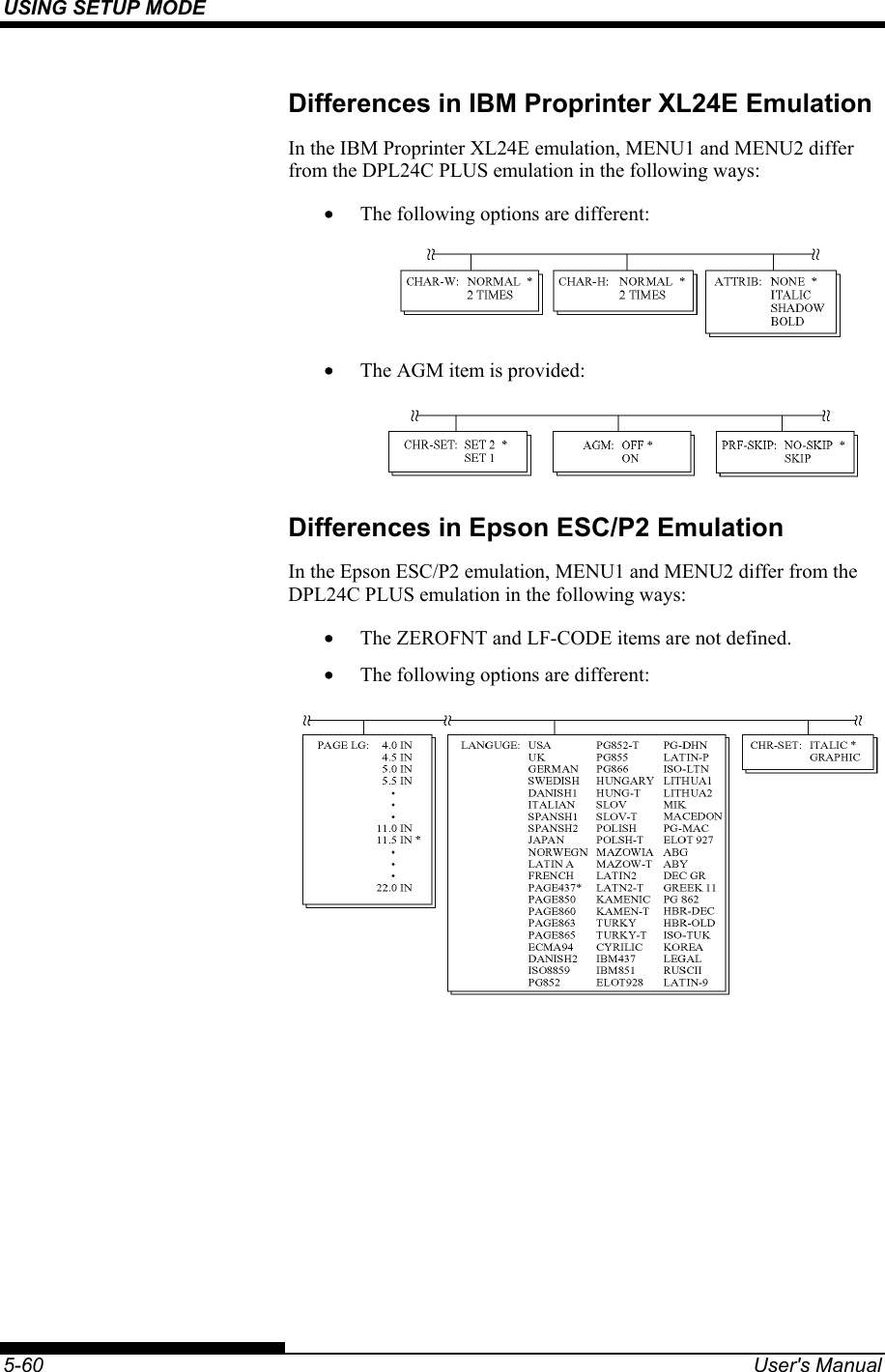
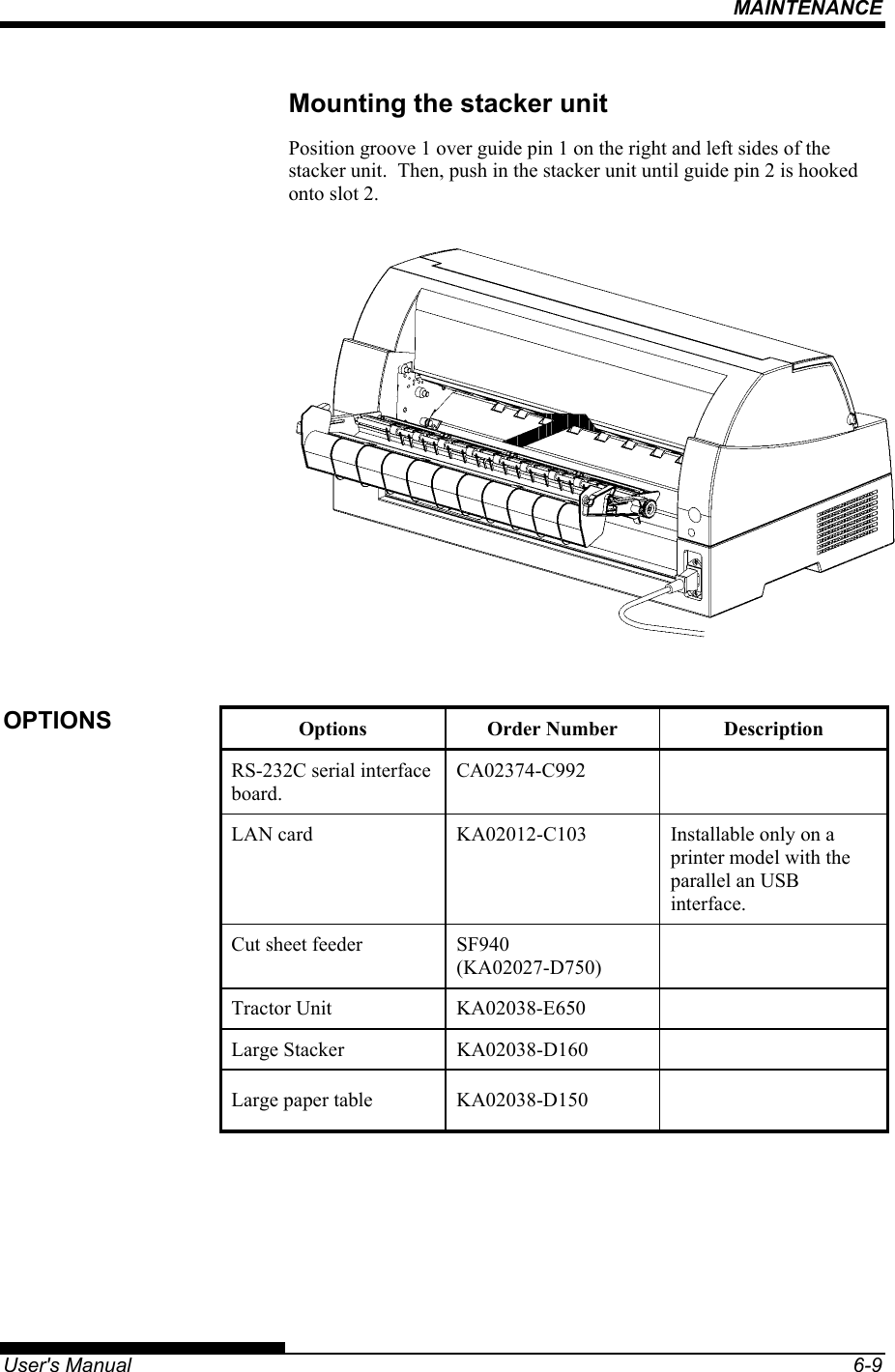
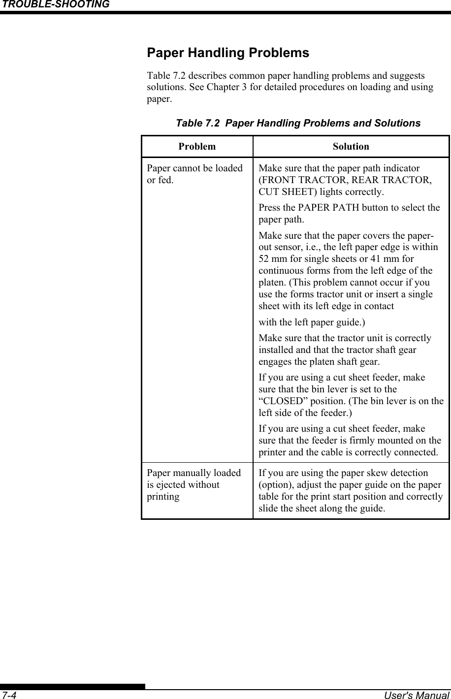
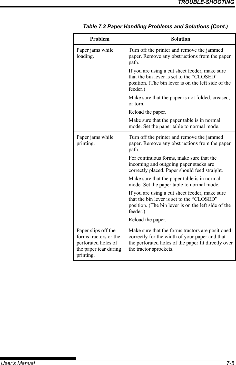
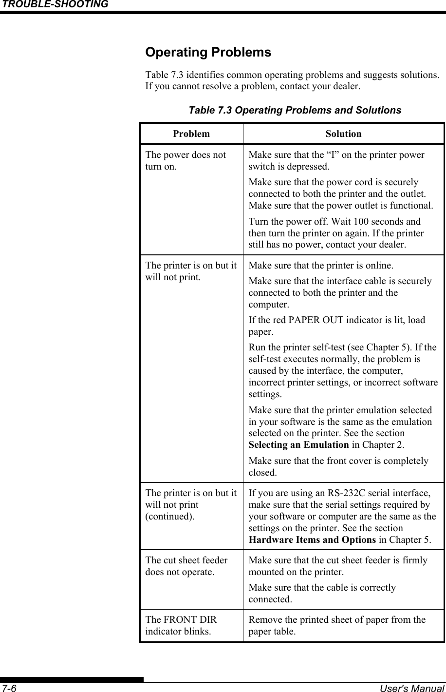
Users Manual 3
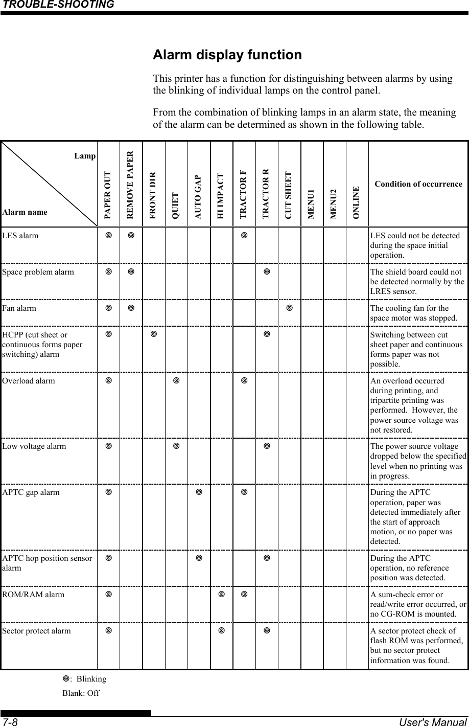
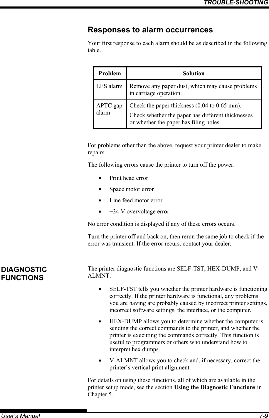
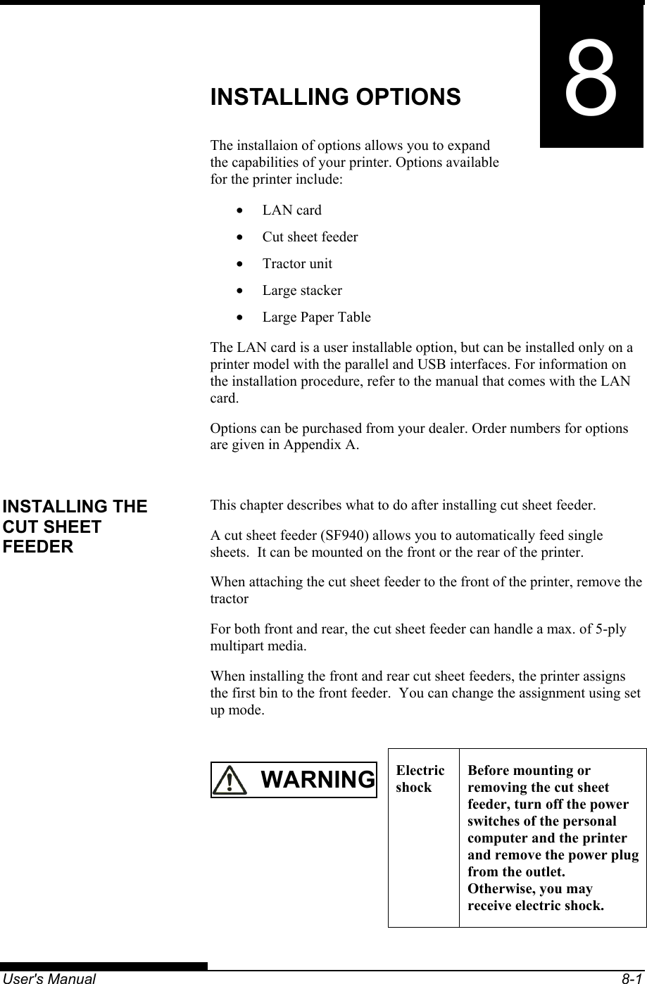
Users Manual 3
Navigation menu
Upload a User Manual
Namespaces
Wiki Guide
HTML
PDF
Info
Views
User Manual
Discussion / Help
Navigation