Fujitsu Isotec 018M33325A Dot Matrix Printer User Manual 1 of 2
Fujitsu Isotec Limited Dot Matrix Printer 1 of 2
UserManual.wiki
>
Fujitsu Isotec
>
018M33325A User Manual
>
User manual 1 of 2
Contents
1.
User manual 1 of 2
2.
User manual 2 of 2
User manual 1 of 2
Navigation menu
Upload a User Manual
Namespaces
Wiki Guide
HTML
PDF
Info
Views
User Manual
Discussion / Help
Navigation


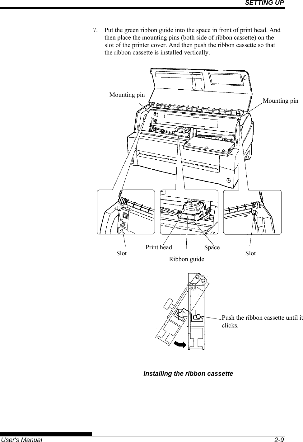
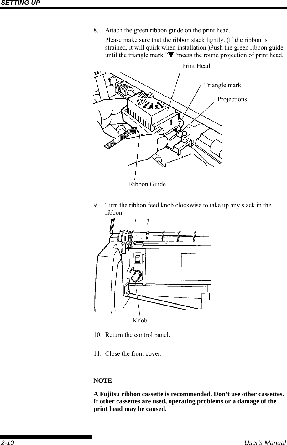
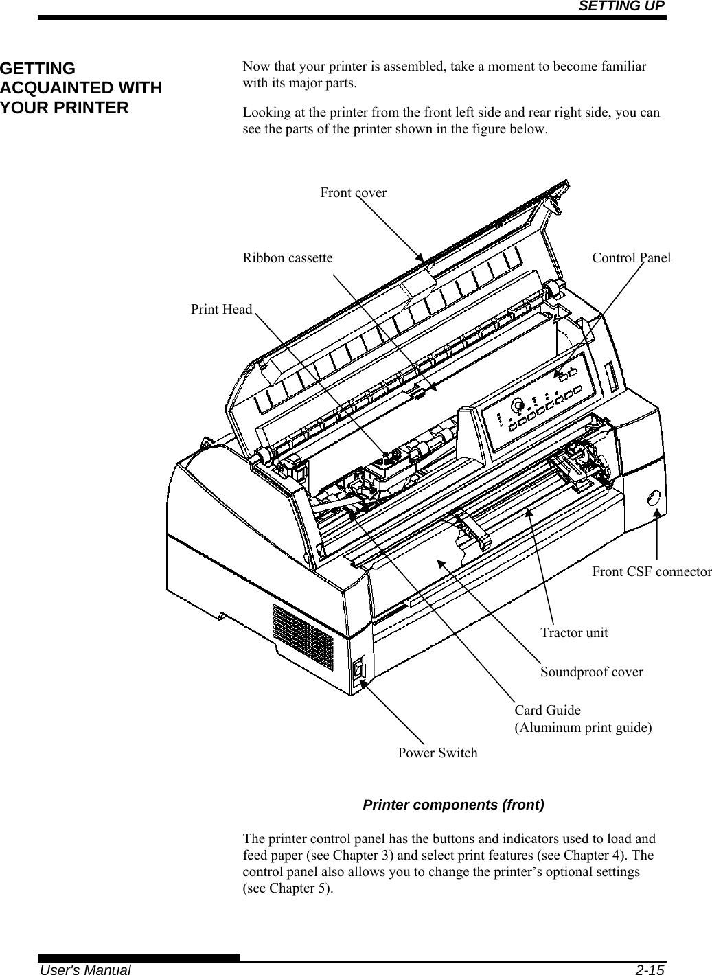
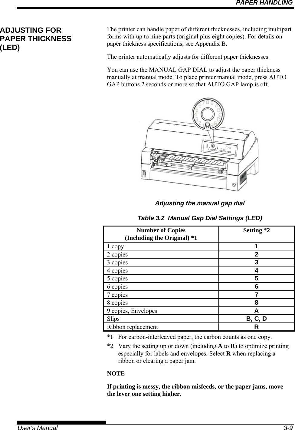
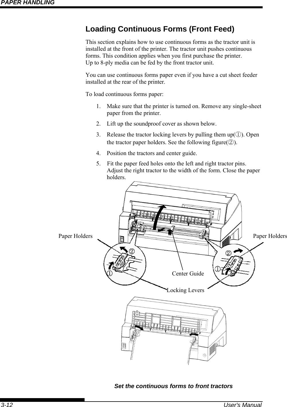
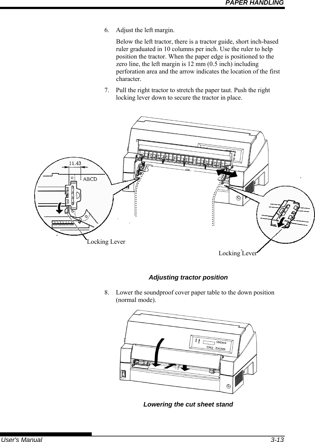
![SETTING UP 2-12 User's Manual Mounting and removing the tractor unit Tractor unit at the front [Removing the tractor unit] Raise the soundproof cover. While pressing the lock levers of the tractor frames located on both sides of the tractor unit, lift out the tractor unit to remove it. [Mounting the tractor unit] 1) Position the U-shaped slots on both sides of the tractor unit over the guide pins of the printer unit. (To set the tractor unit in position, line it up with the groove of the left guide pin. The right guide pin has no groove). 2) Push down the shaft at the front of the tractor unit until it locks with an audible click. (Do not press the lock levers when pushing down the shaft.) Lock lever Lock lever Soundproof cover Guide pin U-shaped slotU-shaped slotGuide pin](https://usermanual.wiki/Fujitsu-Isotec/018M33325A.User-manual-1-of-2/User-Guide-897801-Page-42.png)
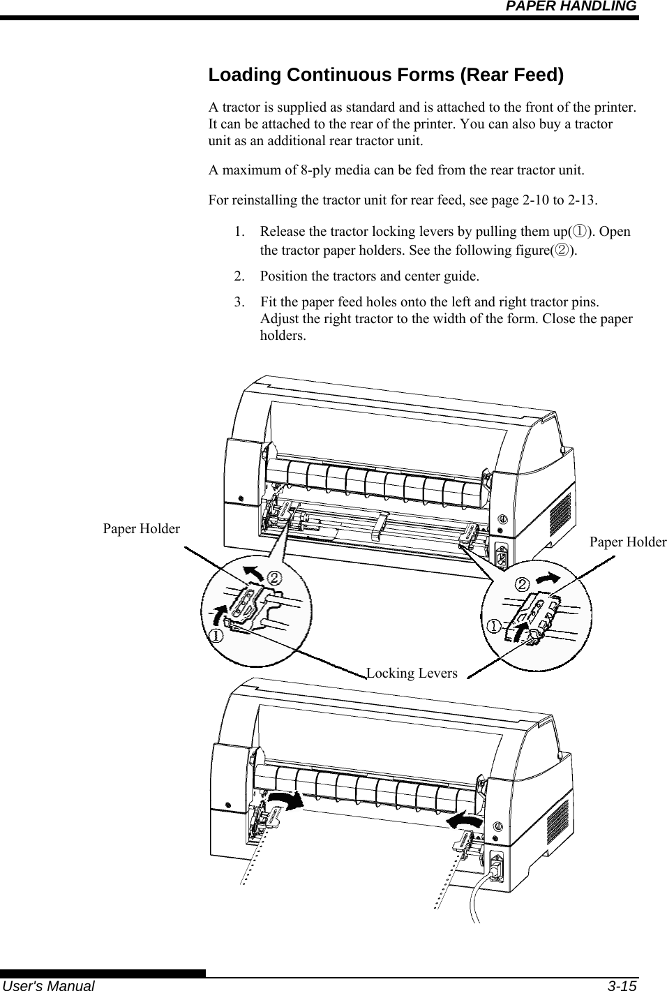
![SETTING UP User's Manual 2-13 3) Verify that the hooks on both sides of the tractor unit are securely hooked onto guide pin 2 as shown in the following figure. Tractor unit at the rear [Removing the tractor unit] While pressing the lock levers of the tractor frames located on both sides of the tractor unit, lift out the tractor unit to remove it.](https://usermanual.wiki/Fujitsu-Isotec/018M33325A.User-manual-1-of-2/User-Guide-897801-Page-43.png)
![SETTING UP 2-14 User's Manual [Mounting the tractor unit] 1) Position the U-shaped slots on both sides of the tractor unit over the guide pins of the printer unit. (To set the tractor unit in position, line it up with the groove of the left guide pin. The right guide pin has no groove). 2) Push down the shaft at the front of the tractor unit until it locks with an audible click. (Do not press the lock levers when pushing down the shaft.) 3) Verify that the hooks on both sides of the tractor unit are securely hooked onto guide pin 2 as shown in the following figure.](https://usermanual.wiki/Fujitsu-Isotec/018M33325A.User-manual-1-of-2/User-Guide-897801-Page-44.png)
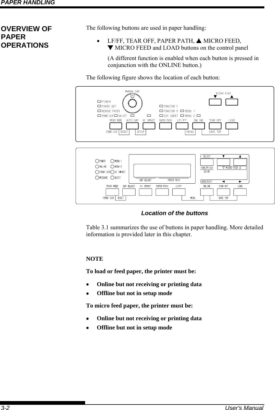
![PAPER HANDLING User's Manual 3-5 This printer has a variety of paper paths and feed directions. Paper Paths and Feed Directions See the following five cases. : Cut sheet : Continuous forms (n) : Input [n] : Output With front tractor (1) Front tractor → Print → Rear eject With rear tractor (2) Rear tractor → Print → Front eject SELECTING PAPER PATH (1)[1](2) [2]](https://usermanual.wiki/Fujitsu-Isotec/018M33325A.User-manual-1-of-2/User-Guide-897801-Page-63.png)
![PAPER HANDLING 3-6 User's Manual With front and rear tractors (either optional) (1) Front tractor → Print → Rear eject (2) Rear tractor → Print → Front eject With front and rear tractors (either optional) and Large paper table (optional) (1) Front tractor → Print → Rear eject (2) Rear tractor → Print → Front eject (3) Paper table → Print → Paper table (4) Paper table → Print → Rear stacker Note Large and small paper table are available as option.(1) (2) [2] [3] (1) (2) [2] [1][3] (3)(4) [4]](https://usermanual.wiki/Fujitsu-Isotec/018M33325A.User-manual-1-of-2/User-Guide-897801-Page-64.png)
![PAPER HANDLING User's Manual 3-7 In the next two cases, the number of cut sheets stacked in the printer may be reduced depending on printing conditions and environments. Follow the notes. With rear tractor and front optional cut sheet feeder and large stacker(optional) and large paper table(optional). (2) Rear tractor → Print → Front eject (3) Paper table → Print → Paper table (4) Paper table → Print → Rear stacker (5) Front cut sheet feeder → Print → Paper table (6) Front cut sheet feeder → Print → Rear stacker With front or rear tractor (either optional)and rear optional cut sheet feeder and large stacker(optional) and large paper table(optional). In addition, the front and rear tractor (either is optional) can be mounted. (1) Front tractor → Print → Rear eject (2) Rear tractor → Print → Front eject (3) Paper table → Print → Paper table (4) Paper table → Print → Rear stacker (7) Rear cut sheet feeder → Print → Paper table (8) Rear cut sheet feeder → Print → Rear stacker (5)(6) (2) [2] [3] [5](3)(4) [4] [6](1)(2) [2] [1][3][7] (3)(4) [4][7][8] [8]](https://usermanual.wiki/Fujitsu-Isotec/018M33325A.User-manual-1-of-2/User-Guide-897801-Page-65.png)
![PAPER HANDLING 3-8 User's Manual With rear tractor and front and rear optional cut sheet feeder and large stacker and large paper table. In addition, the front and rear tractor (either is optional) can be mounted. (2) Rear tractor → Print → Front eject (3) Paper table → Print → Paper table (4) Paper table → Print → Rear stacker (5) Front cut sheet feeder → Print → Paper table (6) Front cut sheet feeder → Print → Rear stacker (7) Rear cut sheet feeder → Print → Paper table (8) Rear cut sheet feeder → Print → Rear stacker NOTES When ejecting cut sheets to the paper table, the REMOVE PAPER indicator blinks after ejecting a cut sheet and stops printing. Before restarting printing, be sure to remove the cut sheet. You must remove cut sheets one by one immediately after ejection. This is required because the printer may load an ejected sheet again or an ejected sheet may push the previous sheets out of the printer. To eject sheets larger than A4 size onto the paper table, the paper table must be replaced with the optional large cut sheet table to prevent ejected sheets from falling off the paper table. When printing thin paper, multipart copy paper, or large size paper, frequently remove the paper from the rear stacker or the paper table. (2) [2] [3][5][7] (3)(4) [4] [7][8] [8] (5)(6) [6]](https://usermanual.wiki/Fujitsu-Isotec/018M33325A.User-manual-1-of-2/User-Guide-897801-Page-66.png)
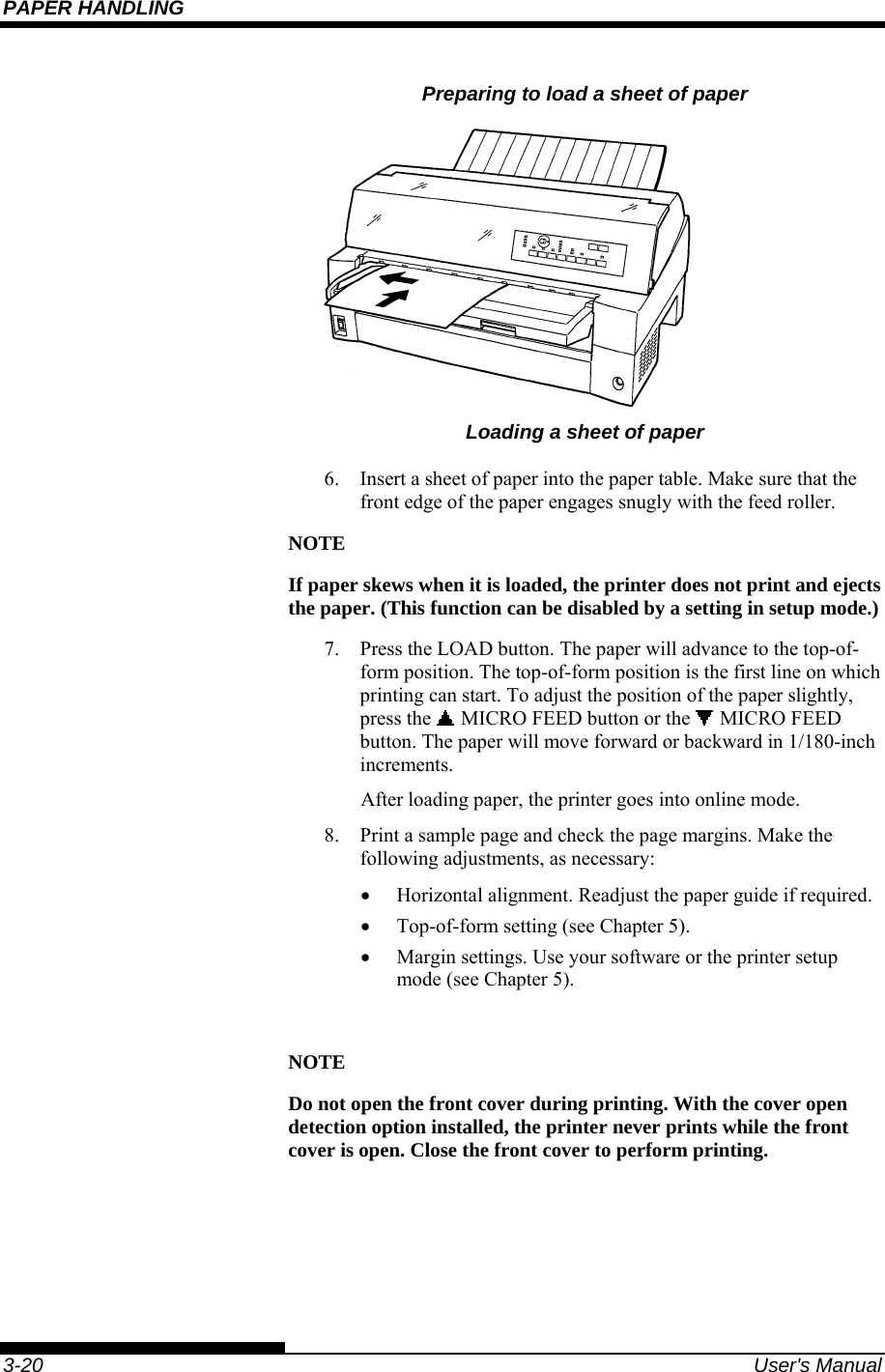
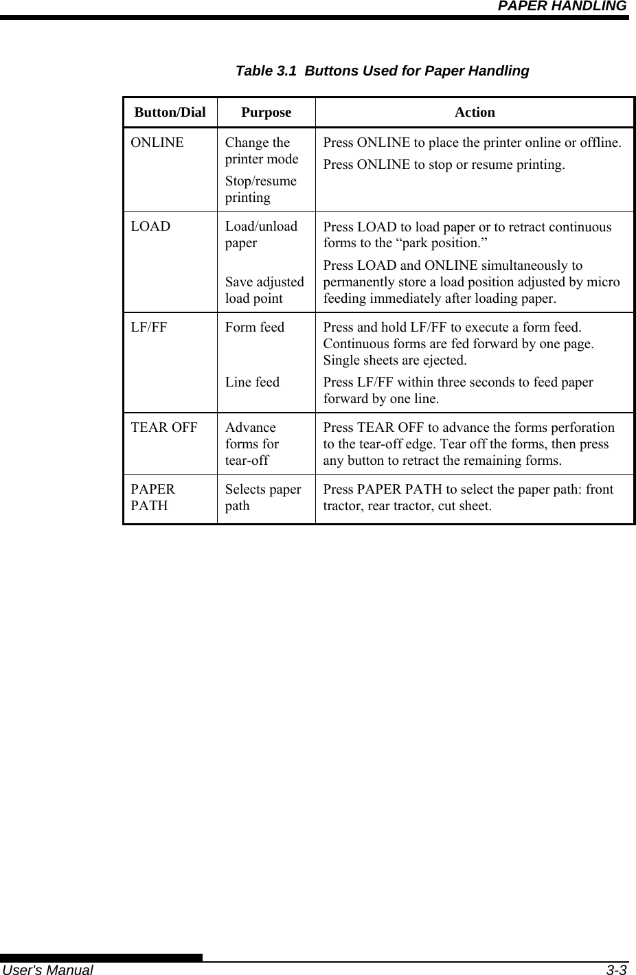
![PAPER HANDLING User's Manual 3-19 This section describes how to load paper from the paper table or cut sheet feeder. The paper table allows paper to be loaded manually, one sheet at a time. A cut sheet feeder allows paper to be loaded automatically from the paper bin. Loading a Paper From The Paper Table. (option) To load a sheet of paper from the paper table: 1. Make sure that the printer is turned on. 2. Press the PAPER PATH button to select CUT SHEET (the indicator lights). 3. Press the FRONT DIR button to select the direction of ejecting single sheets. • Front ejection — FRONTDIR indicator lights. • Rear ejection — FRONTDIR indicator doesn’t light. 4. Adjust the left margin. On the left hand side of the paper table, a scale graduated in units of 1 [mm]. When the paper guide is positioned at scale 0 [mm], the left margin is 5 mm (0.2 inch). Push the lock lever down to secure the guide. 5. Pull the sub guide out as required to accommodate the paper size. NOTE When using the paper whose width is under 100 mm (4 inch), position the paper guide at scale 0 [mm]. USING SINGLE SHEETS 0(zero) Movable guide Lock lever Sub guide](https://usermanual.wiki/Fujitsu-Isotec/018M33325A.User-manual-1-of-2/User-Guide-897801-Page-77.png)