Fujitsu Isotec 018M33325A Dot Matrix Printer User Manual 1 of 2
Fujitsu Isotec Limited Dot Matrix Printer 1 of 2
Contents
- 1. User manual 1 of 2
- 2. User manual 2 of 2
User manual 1 of 2
FUJITSU DL7600
DOT MATRIX PRINTER
USER'S MANUAL

READ THE ENTIRE MANUAL CAREFULLY BEFORE USING THIS PRODUCT.
INCORRECT USE OF THE PRODUCT MAY RESULT IN INJURY OR DAMAGE TO
USERS, BYSTANDERS OR PROPERTY.
While FUJITSU ISOTEC has sought to ensure the accuracy of all information in this manual,
FUJITSU ISOTEC assumes no liability to any party for any damage caused by any error or
omission contained in this manual, its updates or supplements, whether such errors or omissions
result from negligence, accident, or any other cause. In addition, FUJITSU ISOTEC assumes no
liability with respect to the application or use of any product or system in accordance with
descriptions or instructions contained herein; including any liability for incidental or
consequential damages arising therefrom. FUJITSU ISOTEC DISCLAIMS ALL WARRANTIES
REGARDING THE INFORMATION CONTAINED HEREIN, WHETHER EXPRESSED,
IMPLIED, OR STATUTORY.
FUJITSU ISOTEC reserves the right to make changes to any products described herein without
further notice and without obligation.
This product is designed and manufactured for use in standard applications such as office work,
personal devices, household appliances, and general industrial use. This product is not intended
for special uses (nuclear-reactor control in atomic energy facilities, aeronautic and space systems,
air traffic control, operation control in mass transit systems, medical devices for life support, or
missile firing controls in weapons facilities) where particularly high reliability requirements exist,
where the pertinent levels of safety are not guaranteed, or where a failure or operational error
could threaten a life or cause a physical injury (hereafter referred to as “high-risk” use).
Customers considering the use of this product for high-risk applications must have safety-
assurance measures in place beforehand. Moreover, they are requested to consult our sales
representative before embarking on such specialized use.
IMPORTANT NOTE TO USERS
Using This Product in High-risk Situations

User's Manual i
Federal Communications Commission
Radio Frequency Interference Statement
for United States Users
NOTE: This equipment has been tested and found to comply with the
limits for a Class B digital device, pursuant to Part 15B of the FCC Rules.
These limits are designed to provide reasonable protection against
harmful interference in a residential installation. This equipment
generates, uses, and can radiate radio frequency energy and, if not
installed and used in accordance with the instructions, may cause harmful
interference to radio communications. However, there is no guarantee
that interference will not occur in a particular installation. If this
equipment does cause harmful interference to radio or television
reception, which can be determined by turning the equipment off and on,
the user is encouraged to try to correct the interference by one or more of
the following measure:
• Reorient or relocate the receiving antenna.
• Increase the separation between the equipment and receiver.
• Connect the equipment into an outlet on a circuit different from that
to which the receiver is connected.
• Consult the dealer or an experienced radio/TV technician for help.
FCC warning: Changes or modifications not expressly approved by the
party responsible for compliance could void the user’s authority to
operate the equipment.
NOTES
1. Testing of this equipment was performed on model number
M33325A.
2. The use of a nonshielded interface cable with the referenced device
is prohibited. The length of the parallel interface cable must be 3
meters (10 feet) or less. The length of the optional serial interface
cable must be 15 meters (50 feet) or less.
3. The length of the power cord must be 3 meters (9.8 feet) or less.

ii User's Manual
Notice for Canadian Users
This class B digital apparatus (M33325A) meets all requirements of the
Canadian Interference-Causing Equipment Regulations.
Cet appareil (M33325A) numérique de la Classe B respecte toutes les
exigences du Règlement sur le matériel brouilleur du Canada.
Notice for German Users
Bescheinigung des Herstellers/Importeurs
Hiermit wird bescheinigt, daß der/die/das
• M33325B
in Übereinstimmung mit den Bestimmungen der 2004/108/EC und
2006/95/EC ist.
Der Deutschen Bundesport wurde das inverkehrbringen dieses Gerätes
angezeigt und die Berechtigung zur Überprüfung der Serie auf
Einhaltung der Bestimmungen eingeräumt.
Maschinenlärminformations-Verordnung 3. GSGV,
der höchste Schalldruckpegel beträgt 70 dB (A) oder weniger gemäß
EN ISO 7779
Importer / Distributor in EU:
Fujitsu Europe Ltd.,
Hayes Park Central, Hayes End Road, Hayes, Middlesex UB4 8FE, U.K.

User's Manual iii
Energy Saving
As an ENERGY STAR® Partner, FUJITSU ISOTEC LIMITED has
determined that this product meets the ENERGY STAR® guidelines for
energy efficiency.
The International ENERGY STAR® Office Equipment Program is an
international program that promotes energy saving through the use of
computers and other office equipments. The program backs the
development and dissemination of products with functions that
effectively reduce energy consumption. It is an open system in which
business proprietors can participate voluntarily. The targeted products
are office equipment such as computers, displays, printers, facsimiles,
and copiers. Their standards and logos are uniform among participating
nations.
CE Declaration
This product sold in Europe conforms to the standard in accordance with
EC Directives.

iv User's Manual
The contents of this manual may be revised without prior notice and
without obligation to incorporate changes and improvements into units
already shipped.
Every effort has been made to ensure that the information included here
is complete and accurate at the time of publication; however, Fujitsu
Isotec Limited cannot be held responsible for errors and omissions.
Printer model specifications differ with the power supply input voltage
(M33325A; 100-120 or M33325B; 220-240 VAC).
C147-E052-01EN March 2008
Copyright © 2008 FUJITSU ISOTEC LIMITED
Printed in Japan. All rights reserved. No part of this manual may be
reproduced or translated, stored in a database or retrieval system, or
transmitted, in any form or by any means, electronic, mechanical,
photocopying, recording, or otherwise, without the prior written
permission of Fujitsu Isotec Limited.
FUJITSU is a registered trademark and Fujitsu Creative Faces is a
trademark of Fujitsu Limited. Centronics is a trademark of Centronics
Data Computer Coporation. IBM PC and IBM Proprinter XL24E are
trademarks of International Business Machines Corporation. ESC/P2 is a
trademark of Seiko Epson Corporation. Microsoft is a registered
trademark and MS-DOS and Windows are trademarks of Microsoft
Corporation. Nimbus Sans is a registered trademark of URW
Unternehmensberatung Karow Rubow Weber GmbH, Hamburg.
Other product names mentioned in this manual may also be trademarks
of their respective companies.
TRADEMARK
ACKNOWLEDGEMENT

User's Manual v
ABOUT THIS MANUAL
Thank you for buying the Fujitsu DL7600 dot matrix printer. You can
expect years of reliable service with very little maintenance. This manual
explains how to use your printer to full advantage. It is written for both
new and experienced printer users.
This manual describes how to install, set up, and use your printer and
printer options. It also explains how to keep the printer in good working
condition and what to do should something go wrong. Detailed
procedures are provided for first-time users. Experienced users can skip
some of the details, using the table of contents and chapter introductions
to locate information.
This manual has several appendixes, a glossary, and an index. Appendix
A lists supplies and additional documentation and information available
from your dealer or authorized Fujitsu representative. Fujitsu offices are
listed at the end of the manual.
This manual covers model DL7600, a 136-column printer. Each model
has a 100-120 (M33325A) VAC or 220-240 (M33325B) VAC power
supply. A LAN card, a user add-on option, can be installed only on
printer models with the Centronics parallel+USB interfaces. You must
specify these when purchasing the printer.
Other options include a cut sheet feeder can be added by yourself after
purchasing the printer.
DL7600
Basic specifications
Print line at 10 cpi: 136 columns (DL7600)
Control Panel: LED type
LCD type
Interface: Centronics parallel + RS-232C
Centronics parallel + USB + LAN (LAN:user option)
Alternative specification
Power supply: 100-120 VAC (M33325A)
220-240 VAC (M33325B)
User add-on option
LAN card
Cut sheet feeder
Tractor unit
Large Paper Table
Large Stacker
Small paper table
cpi: characters per inch
PRINTER MODELS
AND OPTIONS

vi User's Manual
This manual is organized as follows:
Quick Reference summarizes everyday printer operations. After you
become familiar with the printer, use this section as a memory aid.
Chapter 1, Introduction, introduces the printer and identifies key
features and options that enhance the printer’s capabilities.
Chapter 2, Setting Up, gives step-by-step procedures for setting up the
printer for immediate use and identifies the main parts of the printer. If
this is your first printer, you should read the entire chapter before
attempting to use the printer.
Chapter 3, Paper Handling, explains how to load and use paper with
your printer.
Chapter 4, Printing, covers basic printing operations. This chapter
describes everyday operations from the printer’s control panel, such as
loading paper and selecting print features, in detail. After you become
more familiar with the printer, use Quick Reference at the beginning of
the manual to refresh your memory as needed.
Chapter 5, Using Setup Mode, describes how to change the printer’s
optional settings, such as print features, hardware options, and top-of-
form. Most settings only affect print features such as the typestyle and
page format. Note that certain settings directly affect hardware and
software compatibility. Refer to this chapter as indicated in Chapter 2 or
as required.
Chapter 6, Maintenance, explains basic maintenance procedures for
this printer.
Chapter 7, Trouble-Shooting, describes problem-solving techniques.
Before you contact your dealer for help, check the list of problems and
solutions provided in this chapter.
Chapter 8, Installing Options, describes the options available for the
printer and explains how to install them.
At the end of this manual, you will find several appendixes, a glossary,
and an index. Appendix A gives order numbers for printer supplies,
options, and publications. Other appendixes provide additional technical
information about the printer.
ORGANIZATION

User's Manual vii
Special information, such as warnings, cautions, and notes, are indicated
as follows:
WARNING
A WARNING indicates that personal injury may result if you do not
follow a procedure correctly.
CAUTION
A CAUTION indicates that damage to the printer may result if you do not
follow a procedure correctly.
NOTE
A NOTE provides “how-to” tips or suggestions to help you perform
a procedure correctly. NOTEs are particularly useful for first-time
users.
For Experienced Users:
If you are familiar with this printer or with dot matrix printers in general,
this information will help you use the manual effectively.
CONVENTIONS
viii User's Manual
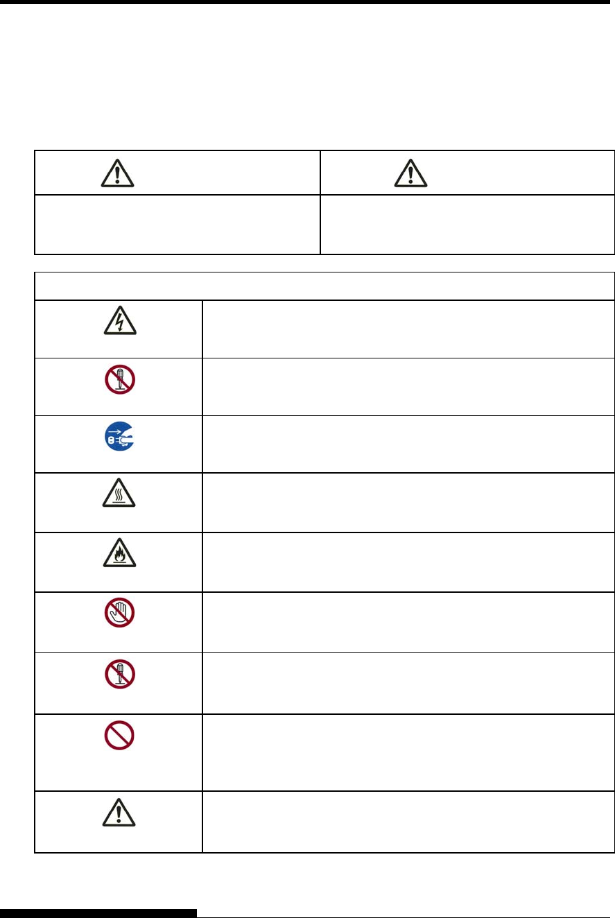
z Warning symbols
Various graphic symbols are used in this manual. They serve as signs to help users of this product use
the product safely and correctly as well as prevent damage and personal injury to the users or bystanders.
The following tables show and explain each symbol. Be sure that you understand the meaning of each
symbol before reading the manual.
WARNING CAUTION
A WARNING indicates that death or serious
personal injury may result if you do not follow a
procedure correctly.
A CAUTION indicates that personal injury or
property damage may result if you do not follow a
procedure correctly.
Examples and explanations of graphic symbols
U indicates a warning or caution item. By itself, the image in this
symbol suggests the meaning of the warning or caution (the example
on the left is a caution of possible electric shock).
: indicates a prohibited action. The image in or beside this symbol
expresses the prohibited action (the example on the left indicates that
disassembly is prohibited).
z indicates a direction that must be observed. The image in this
symbol shows the direction (the example on the left shows the
direction in which a power plug is disconnected from an outlet).
Caution: Hot
This symbol and accompanying statement indicate a risk of injury from
a hot object.
Caution: Flammable
This symbol and accompanying statement indicate a risk of fire.
Do not touch
This symbol and accompanying statement indicate a risk of injury from
touching part of the equipment.
Do not disassemble
This symbol and accompanying statement indicate a risk of injury,
such as from electric shock, caused by disassembling the equipment.
General prohibited
action
This symbol and accompanying statement indicate a general prohibited
action.
General caution
This symbol and accompanying statement indicate a general caution.
User's Manual ix
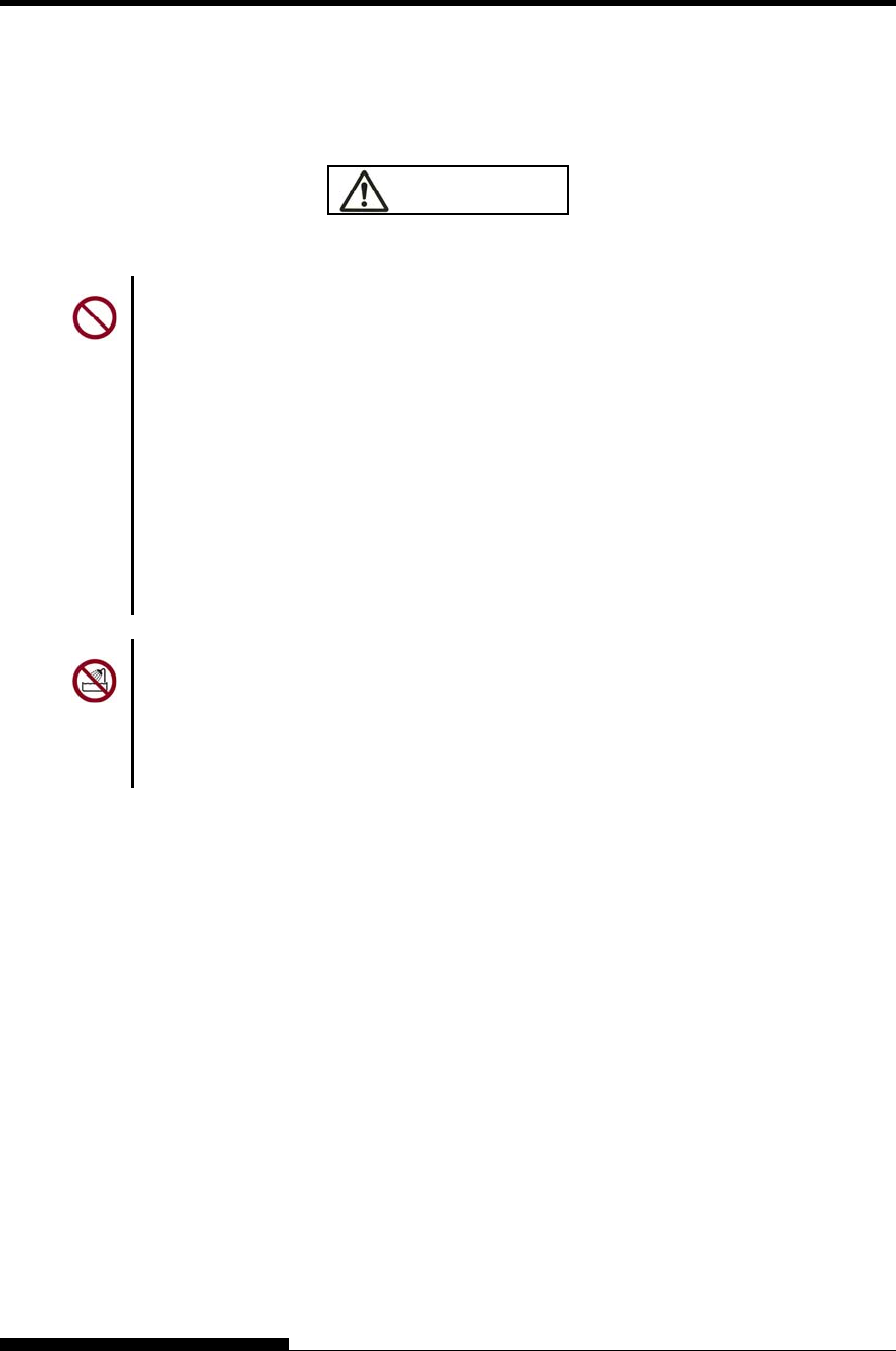
Notes on Safety
WARNING
WARNING
Do not place a container containing water, such as a vase, potted plant, and drinking glass,
or a metal object on or near the printer.
Otherwise, electric shock or fire may result.
Do not place the printer in a humid or dusty area, in an area with explosive fumes, an area
with poor ventilation or close to a fire.
Otherwise, electric shock or fire may result.
Use only one of the power cords included with this product, for this product. Do not use
any other power cord for this product.
Otherwise, electric shock or fire may result.
Do not use this product in an area exposed to a high level of moisture, such as a bathroom
and shower room.
Otherwise, electric shock or fire may result.
x User's Manual
WARNING
When mounting or removing an optional device or component, turn off the power to the
printer and personal computer and disconnect their power plugs from the outlets before
performing the work.
Otherwise, electric shock may result.
Connect only Fujitsu-recommended optional devices and components.
Otherwise, electric shock, fire, or failure may result.
CAUTION
Do not block openings in the printer (e.g., ventilation openings).
If ventilation openings are blocked, heat accumulates inside the printer, possibly resulting
in a fire.
Do not place a heavy object on the printer. Also, do not subject the printer to shocks.
Otherwise, the printer may become unbalanced, causing it to fall, and possibly resulting in
personal injury.
Do not place the printer in an area exposed to strong vibration or an unstable area such as
on a slope.
Otherwise, the printer may fall or topple, possibly resulting in personal injury.
Do not leave the printer in an area exposed to direct sunlight for a long time, such as inside
a car under the sun or any other area subjected to high temperatures.
Otherwise, the printer surface heats up, possibly melting covers or resulting in other
deformities, or the inside of the printer may become extremely hot, possibly resulting in
fire.
Before moving the printer, be sure to disconnect the power plug from the outlet and
disconnect all connected cables from the printer.
Otherwise, the power cord may be damaged, possibly resulting in electric shock or fire, or
the printer may fall or topple, possibly resulting in personal injury.
Before connecting or disconnecting a printer cable, be sure to turn off the power to the
printer and personal computer.
Performing that and related work without the power turned off may result in a personal
computer or printer failure.
User's Manual xi
Notes about the printer in operation
WARNING
If the printer is making a strange noise, which indicates a problem, discontinue printer
operation. Request your printer dealer to fix the problem.
Continued operation of the printer without repairs may result in electric shock or fire.
Do not use a power source whose voltage is other than that indicated. Also, an excessive
number of plugged-in power cords must not be connected to a single outlet.
Otherwise, electric shock or fire may result.
Do not spill any liquid, such as water, on the printer.
Otherwise, electric shock or fire may result.
Do not damage or modify the power cord.
The power cord may be damaged by placing a heavy object on it, stretching it excessively,
forcibly bending it, twisting it, or heating it, and this may result in electric shock or fire.
Do not use the power cord if it or the power plug is damaged or the plug does not fit
securely in the outlet receptacle.
Using the power cord in that condition may result in electric shock or fire.
Do not insert the power cord into an outlet or turn on the power to the printer when any of
its covers has been removed.
Otherwise, electric shock or fire may result.
Prevent foreign objects, such as metal shards and inflammable materials, from being
inserted or dropped into any openings in the printer (e.g., ventilation openings).
Otherwise, electric shock or fire may result.
Do not disconnect the power plug from the outlet while the power to the printer is turned
on.
Otherwise, the plug becomes deformed, possibly resulting in fire.
Do not remove the main printer cover or the cover for the cable connectors except as
necessary. To check and repair internal components, request your printer dealer to do so.
Some internal components use high voltage, and touching them may result in electric
shock.
Do not modify the printer by yourself.
Otherwise, electric shock or fire may result.
Do not connect or disconnect the power plug with wet hands.
Otherwise, electric shock may result.
xii User's Manual
WARNING
If excessive heat, smoke, a strange odor, or a strange noise is coming the printer or any
other abnormality is observed, immediately turn off the power to the printer by using the
power switch, and be sure to disconnect the power plug from the outlet.
Then, after verifying the end of the abnormality (e.g., no more smoke is coming from the
printer), request your printer dealer to make repairs. Do not repair the printer by yourself
as doing so is dangerous.
Continued use of the printer when it is operating abnormally may result in electric shock or
fire.
If a foreign object (e.g., water or other liquid, metal shard) has entered the printer,
immediately turn off the power to the printer by using the power switch, and disconnect the
power plug from the outlet. Then, contact your printer dealer.
Continued use of the printer in that condition may result in electric shock or fire.
Customers who use the printer near children should take especial care regarding this point.
If the printer is dropped or a cover is damaged, turn off the power to the printer by using
the power switch, and disconnect the power plug from the outlet. Then, contact your
printer dealer.
Continued use of printer in that condition may result in electric shock or fire.
Before performing cleaning, maintenance, or troubleshooting work on the printer, switch
off the power switch, and be sure to disconnect the power plug from the outlet.
Performing that work on the printer without the power turned off may result in burns or
electric shock.
Dust accumulates on or near the metal parts of the power plug, so wipe away that dust with
a dry cloth.
Continued use of printer in that condition may result in fire.
Do not drop or strike the printer, such as by hitting it against something.
Otherwise, a failure may result.
User's Manual xiii
CAUTION
Insert the power plug completely into an outlet so that it is securely connected.
Otherwise, electric shock or fire may result.
Exercise caution to keep loose clothing, hair, neckties, etc. away from paper feed- or
ejection openings, and tractors while the printer is operating.
Otherwise, personal injury may result.
When disconnecting the power plug from the outlet, pull it out while grasping the plug, not
the cord.
If you pull it out while grasping the cord, the insulation may be damaged or the cable core
may be exposed or damaged, possibly resulting in electric shock or fire.
Do not cover or wrap the printer with a cloth or anything else while it is operating.
Otherwise, heat accumulates, possibly resulting in fire.
Do not use the power cord with it bunched together.
Otherwise, heat accumulates, possibly resulting in fire.
If the printer operates when the front cover is unclosed, immediately turn the printer off,
and unplug the power code from wall outlet.
Then contact your printer dealer to make repair of safety interlock.
Continued use of the printer in that condition, operation of the mechanism inside of the
front cover may become a cause of an injury.
If the printer is not to be used for a long time, disconnect the power plug from the outlet
for safety reasons.
Otherwise, electric shock or fire may result.
If a lightning storm is in nearby, disconnect the power plug from the outlet.
Leaving the plug connected to the outlet may result in damage to the printer or other
property damage.
The print head and internal frames become extremely hot during printer operation and
remain so immediately afterwards. Do not touch these parts until sufficient time has
passed to allow them to cool.
Otherwise, burns or personal injury may result.
xiv User's Manual
CAUTION
Do not touch the paper feed- or ejection openings while the printer is operating.
Otherwise, personal injury may be result.
Do not touch the printer cable connectors or the metal part of the print head.
Otherwise, personal injury or a printer failure may result.
Do not touch the print head while it is moving.
Otherwise, burns or personal injury may result.
Note that continuous forms that are fed in the reverse direction continuously may come off
the paper feed tractors.
Operate the printer with the paper thickness lever set to the appropriate paper thickness.
Use only an original ribbon cassette that is specified as suitable by Fujitsu.
Textile fibers accumulate on components inside the printer and parts of the roller, so clean
these parts regularly.
Do not turn the ribbon feed knob in the reverse direction.
Otherwise, the ribbon may become jammed and stuck.
If printing is started with a slack ribbon, the ribbon may become tangled or the ribbon feed
mechanism may become locked.
The print head is extremely hot immediately after printing. When replacing the ribbon,
verify that the print head is sufficiently cool before setting the print head to the ribbon
replacement position.

User's Manual xv
TABLE OF CONTENTS
QUICK REFERENCE ....................................................QR-1
CHAPTER 1 INTRODUCTION ...................................................................... 1-1
FEATURES.......................................................................1-1
MODELS...........................................................................1-3
OPTIONS..........................................................................1-3
CHAPTER 2 SETTING UP ............................................................................ 2-1
SELECTING A GOOD LOCATION ..................................2-1
UNPACKING THE PRINTER ...........................................2-2
Checking Options and Supplies ..................................2-4
ASSEMBLING THE PRINTER .........................................2-5
Setting the paper table .....................................................
Handling the paper table ............................................. 2-5
Installing the Ribbon cartridge..................................... 2-7
Mounting and removing the tractor unit.....................2-12
GETTING ACQUAINTED WITH YOUR PRINTER......... 2-15
CONNECTING THE POWER CORD.............................2-17
TESTING THE PRINTER (OFFLINE) ............................2-18
Loading Paper for the Self-Test.................................2-18
Printing the Self-Test ................................................. 2-18
CONNECTING THE PRINTER TO YOUR
COMPUTER ...................................................................2-21
Selecting a Parallel Interface Cable ..........................2-21
Selecting a Serial Interface Cable ............................. 2-21
Selecting a USB Cable..............................................2-22
Selecting a LAN cable ............................................... 2-22
Connecting the Interface Cable.................................2-22
SELECTING AN EMULATION .......................................2-23
PRINTING A SAMPLE PAGE (ONLINE)........................ 2-26
INSTALLING THE PRINTER DRIVER...........................2-28
CHAPTER 3 PAPER HANDLING.................................................................. 3-1
SELECTING PAPER ........................................................ 3-1
OVERVIEW OF PAPER OPERATIONS ..........................3-2
SELECTING PAPER PATH.............................................. 3-5
Paper Paths and Feed Directions................................3-5
ADJUSTING FOR PAPER THICKNESS..........................3-9
USING SINGLE SHEETS............................................... 3-19
Loading a Single Sheet of Paper............................... 3-19
Loading Paper from the Cut Sheet Feeder
(Option)......................................................................3-21
Ejecting Single Sheets...............................................3-23
USING CONTINUOUS FORMS .....................................3-11
Positioning the Paper Stack ...................................... 3-11
Loading Continuous Forms (Front Feed) ..................3-12
Loading Continuous Forms (Rear Feed)................... 3-15
Unloading Continuous Forms....................................3-16
Tearing Off Continuous Forms ..................................3-17

xvi User's Manual
FEEDING AND POSITIONING PAPER..........................3-24
Line Feed/Form Feed ................................................3-24
Micro Feed.................................................................3-24
Load Position Adjust ..................................................3-24
TIPS ON PAPER HANDLING.........................................3-26
General Tips ..............................................................3-26
Multipart Forms..........................................................3-26
Envelopes ..................................................................3-26
Labels.........................................................................3-26
CHAPTER 4 PRINTING .................................................................................4-1
MULTIPART FORMS (HI IMPACT MODE) ......................4-1
SELECTING PRINT FEATURES......................................4-6
Using Commercial Software ........................................4-6
Using the Control Panel...............................................4-7
Selecting MENU1 or MENU2.......................................4-8
STARTING OR STOPPING PRINTING............................4-3
Starting Printing ...........................................................4-3
Stopping Printing..........................................................4-3
Resuming from a Paper-Out........................................4-3
Printing the remaining lines on a page ........................4-3
Continuing printing after supplying paper ....................4-4
Resuming after an Area Over warning ........................4-4
REMOVING PRINTED PAGES ........................................4-5
Removing Single Sheets..............................................4-5
Removing Continuous Forms ......................................4-5
CLEARING THE PRINT BUFFER ....................................4-5
CHAPTER 5 USING SETUP MODE ..............................................................5-1
HOW TO USE THIS CHAPTER .......................................5-1
ENTERING SETUP MODE...............................................5-2
OVERVIEW OF SETUP MODE........................................5-4
Setup Mode Example...................................................5-5
Points to Remember ....................................................5-7
PRINTING A LIST OF SELECTED OPTIONS .................5-7
DECIDING WHICH OPTIONS TO CHANGE..................5-12
MENU1 AND MENU2 ITEMS AND OPTIONS ...............5-14
Resetting MENU1 and MENU2 .................................5-28
CHANGING HARDWARE OPTIONS .............................5-28
CHANGING PRINT POSITION ADJUSTMENT
OPTIONS........................................................................5-33
CHANGING CONFIGURATION OPTIONS....................5-39
HEAD GAP ADJUSTMENT ITEMS AND OPTIONS ......5-50
EXITING AND SAVING ..................................................5-51
Procedure ..................................................................5-51
RESETTING DEFAULTS................................................5-52
Resetting Power-On Defaults ....................................5-52
Resetting Factory Defaults ........................................5-52
Resetting Factory Defaults in MENU1 and MENU2 ..5-52
USING THE DIAGNOSTIC FUNCTIONS.......................5-54
Printing the Self-Test .................................................5-54
Procedure ..................................................................5-54
Printing Hex Dumps...................................................5-56

User's Manual xvii
Procedure ..................................................................5-56
Checking Vertical Print Alignment (V-ALMNT)..........5-58
Procedure ..................................................................5-58
SETUP MODE REFERENCE......................................... 5-60
DPL24C PLUS ORGANIZATION ..............................5-61
Differences in IBM Proprinter XL24E Emulation ....... 5-64
Differences in Epson ESC/P2 Emulation ..................5-64
ONLINE SETUP MODE.................................................. 5-65
CHAPTER 6 MAINTENANCE ....................................................................... 6-1
CLEANING........................................................................6-1
Cleaning and Vacuuming the Printer........................... 6-1
Cleaning the Platen ..................................................... 6-2
REPLACING THE RIBBON..............................................6-3
REPLACING THE PRINT HEAD...................................... 6-8
Opening and closing the control panel......................6-12
Removing the stacker unit.........................................6-12
Mounting the stacker unit ..........................................6-13
CHAPTER 7 TROUBLE-SHOOTING ............................................................ 7-1
SOLVING PROBLEMS..................................................... 7-1
Print Quality Problems.................................................7-1
Paper Handling Problems............................................ 7-5
Operating Problems..................................................... 7-7
Printer Failures ............................................................7-8
Alarm display function .................................................7-9
Responses to alarm occurrences..............................7-10
DIAGNOSTIC FUNCTIONS ...........................................7-11
GETTING HELP .............................................................7-11
CHAPTER 8 INSTALLING OPTIONS ........................................................... 8-1
INSTALLING THE CUT SHEET FEEDER .......................8-1
Installing on the front side of the printer ...................... 8-2
Installing on the rear side of the printer ....................... 8-4
Removing the Cut Sheet Feeder................................. 8-7
INSTALLING THE TRACTOR UNIT................................. 8-8
INSTALLING THE LARGE STACKER ............................. 8-9
INSTALLING THE LARGE PAPER TABLE.................... 8-11
APPENDIX A SUPPLIES AND OPTIONS ......................................................A-1
SUPPLIES ........................................................................A-1
OPTIONS..........................................................................A-1
APPENDIX B PRINTER AND PAPER SPECIFICATIONS .............................B-1
PHYSICAL SPECIFICATIONS.........................................B-1
FUNCTIONAL SPECIFICATIONS....................................B-2
PERFORMANCE SPECIFICATIONS...............................B-5
PAPER SPECIFICATIONS...............................................B-6
Print Area.....................................................................B-6
Paper Thickness..........................................................B-8

xviii User's Manual
APPENDIX C COMMAND SETS.................................................................... C-1
FUJITSU DPL24C PLUS ................................................. C-2
Bar Code Printing Control......................................... C-14
IBM PROPRINTER XL24E EMULATION ...................... C-22
EPSON ESC/P2 EMULATION....................................... C-27
APPENDIX D INTERFACE INFORMATION................................................... D-1
PARALLEL INTERFACE ................................................. D-1
Compatible Mode........................................................ D-2
Nibble Mode................................................................ D-4
Data Transmission Timing .......................................... D-6
SERIAL INTERFACE....................................................... D-7
Serial Options ............................................................. D-8
Cable Wiring ............................................................... D-8
Serial Protocols......................................................... D-10
USB INTERFACE .......................................................... D-11
Cable......................................................................... D-11
Specification.............................................................. D-11
LAN INTERFACE........................................................... D-12
Cable......................................................................... D-12
APPENDIX E CHARACTER SETS .................................................................E-1
CHARACTER SETS 1 AND 2 (DPL24C PLUS AND
IBM XL24E EMULATION)................................................ E-1
ITALIC AND GRAPHICS CHARACTER SETS
(ESC/P2 EMULATION).................................................... E-2
NATIONAL CHARACTER SETS (ALL
EMULATIONS)................................................................. E-4
NATIONAL CHARACTER SETS (DPL24C PLUS
AND IBM XL24E EMULATION)..................................... E-15
NATIONAL CHARACTER SETS (ESC/P2
EMULATION)................................................................. E-17
NATIONAL CHARACTER SETS AND SUPPORTED
RESIDENT FONTS (ALL EMULATIONS) ..................... E-20
APPENDIX F RESIDENT FONTS ...................................................................F-1
INDEX............................................................................................................... IN-1
FUJITSU OFFICES ................................................................... Inside back cover
User's Manual QR-1
Q
QUICK REFERENCE
QUICK REFERENCE
Quick Reference is written for experienced users —
users who are familiar with how the printer works,
but who may need to refresh their memory
occasionally. Only the printer’s normal (non-setup)
mode is covered. For details on setup mode, see Chapter 5.
Normal mode operation includes everyday operations, such as paper
handling and font selection. The printer comes up in normal mode when
turned on.
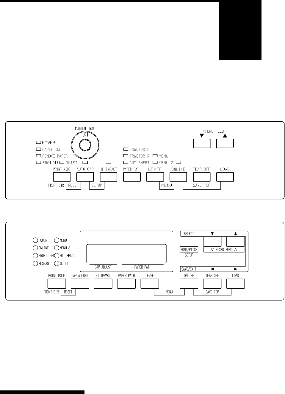
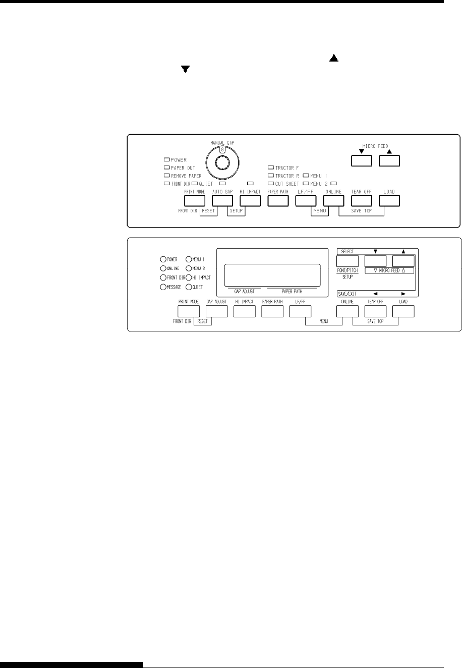
LED type Control panel
LCD type Control panel
The table on the next page lists normal mode operations with online and
offline conditions and gives the required user response.
Operations are listed by functions.
QUICK REFERENCE
QR-2 User's Manual
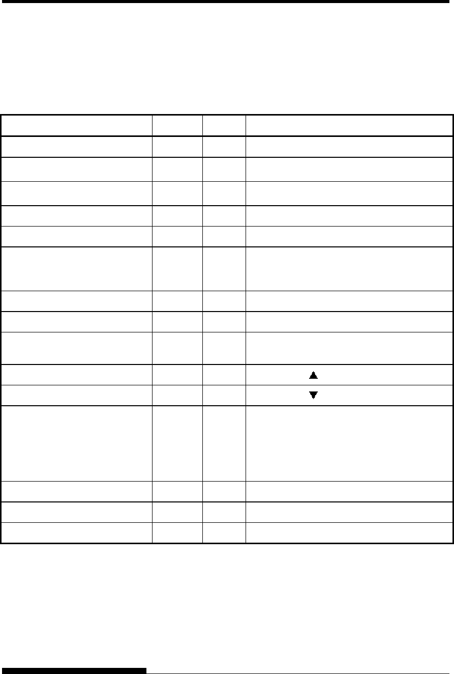
Printer Operations (Normal Mode)
9: Operation can be performed when the printer is in this state.
— : Operation cannot be performed when the printer is in this state.
N/A: Does not apply.
Operation Online Offline Required Response
Enter normal mode N/A N/A Turn printer on. (Press I on the power switch.)
Place printer offline
(Stop printing) 9 — Press ONLINE.
So that ONLINE lamp is off.
Place printer online
(Start printing) — 9 Press ONLINE.
So that ONLINE lamp lights.
Load paper 9 9 Press LOAD.
Line feed (forward) 9 9 Press LF/FF within three seconds.
Unload paper to park position
(both front and rear-fed
continuous forms)
9 9 Press LOAD.
Form feed (forward) 9 9 Press and hold LF/FF until the operation starts.
Eject single sheets 9 9 Press and hold LF/FF until the operation starts.
Tear off forms
(continuous forms only)
9 9 Press TEAR OFF. Tear off forms, then press
any button to retract forms.
Micro feed (backward) 9 9 Press MICRO .
Micro feed (forward) 9 9 Press MICRO .
Select a direction from which cut
sheet is ejected.
— 9 Press FRONT DIR.
When FRONT DIR lamp lights, cut sheet is
ejected to the front side.
When FRONT DIR lamp is off, cut sheet is
ejected to the rear side.
Set/reset QUIET MODE. 9 — Press PRINT MODE.
Set/reset high impact mode 9 9 Press HI IMPACT.
Select a paper input source 9 9 Press PAPER PATH.
QUICK REFERENCE
User's Manual QR-3
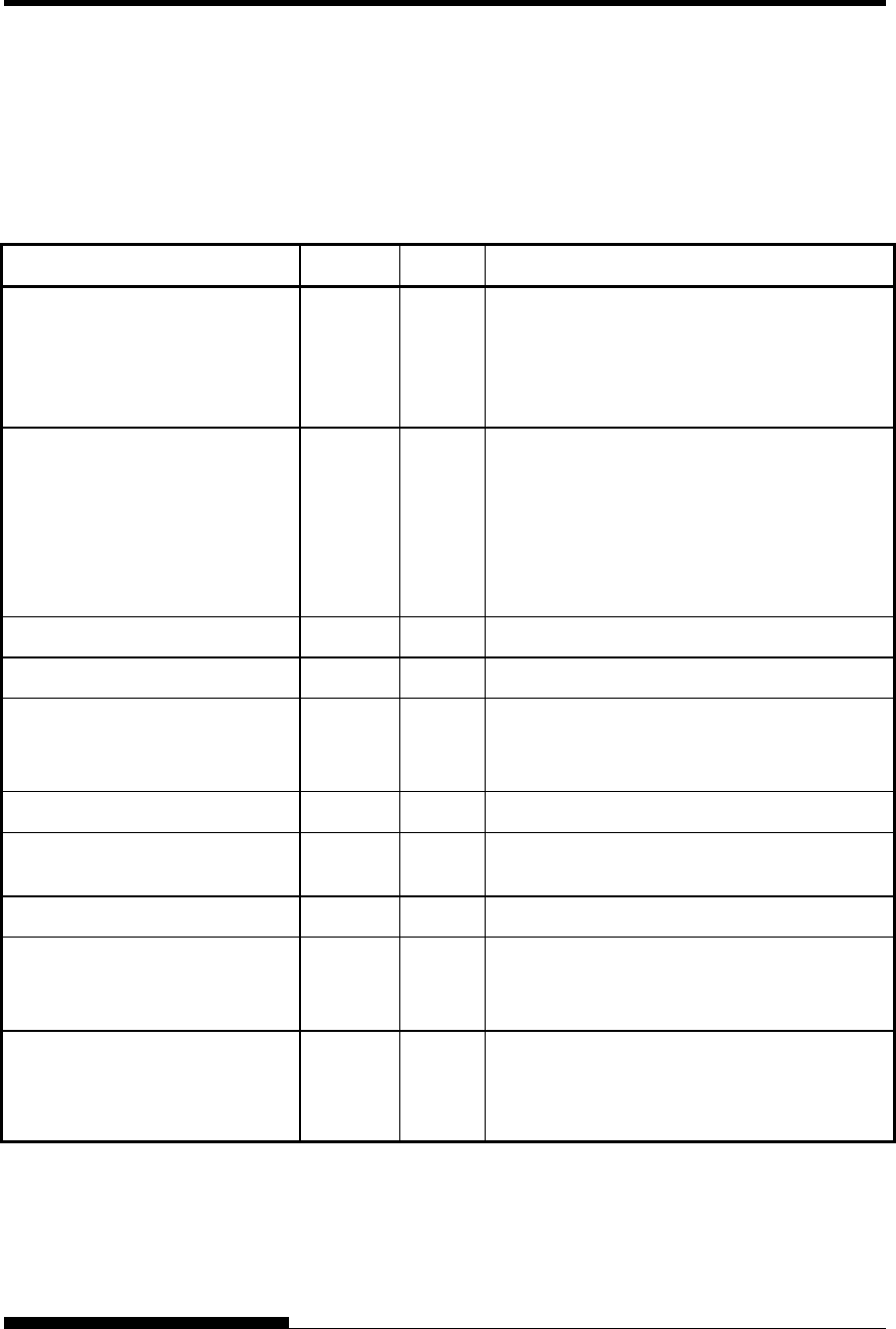
Printer Operations (Normal Mode) (Cont.)
9: Operation can be performed when the printer is in this state.
— : Operation cannot be performed when the printer is in this state.
N/A: Does not apply.
Operation Online Offline Required Response
Select auto adjusting for paper
thickness.
9 9 (LED type)
Press AUTO GAP 2 second or more.
So that AUTO GAP lamp lights
(LCD type)
Press GAP ADJUST.
So that LCD display “AUTO”
Adjust for paper thickness
manually
9 9 (LED type)
Press AUTO GAP 2 second or more.
So that AUTO GAP lamp is off.
Then manual gap dial become effective.
(LCD type)
Press GAP ADJUST repeatedly.
So that LCD display
“GAP-1~GAP9,GAP-A~GAP-D
Save adjusted load positions 9 9 Press ONLINE and LOAD.
Select MENU1 or MENU2 — 9 Press ONLINE and LF/FF.
Clear print buffer — 9 (LED type)
Press FRONT DIR and AUTO GAP.
(LCD type)
Press PRINT MODE and GAP ADJUST.
Reset power-on defaults 9 9 Turn printer off, then on.
Start/stop/resume printing 9 9 Start: Send print command.
Stop/resume: Press ONLINE.
Resume printing after paper — 9 Press ONLINE.
Enter setup mode — 9 (LED type)
Press AUTO GAP and HI IMPACT.
(LCD type)
Press SET UP.
Exit to normal mode
Self-test printing
9 9 Start: Turn printer off. Press LF/FF while
turning printer on.
Pause/resume: Press LOAD.
Exit: Press ONLINE.

QUICK REFERENCE
QR-4 User's Manual
User's Manual 1-1
1
CHAPTER 1 INTRODUCTION
INTRODUCTION
Congratulations on purchasing this printer. This
printer is a compact, versatile, flat paper path
printer that offers maximum compatibility with
today’s software packages and personal computers.
The 24-wire print head provides crisp, clear printing for business, office,
and home environments. This printer is also easy to install and use.
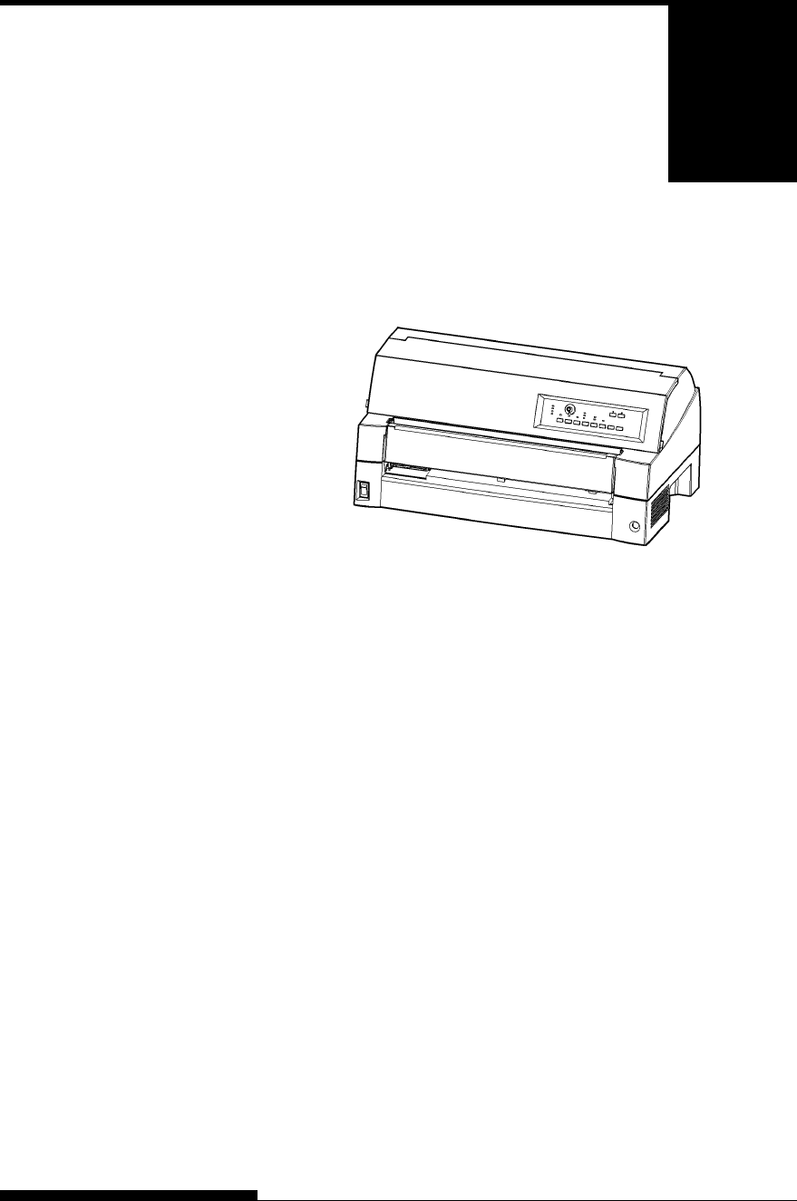
DL7600 dot matrix printer (136 columns)
Key printer features, models and options are listed in the next two
sections.
• Software compatibility. This printer, which operates primarily with
the Fujitsu DPL24C PLUS command set, is compatible with the
IBM Proprinter XL24E command set and the Epson ESC/P2
command set.
• Various character sets. As basic character sets, IBM PC character
sets 1 and 2 are available for the Fujitsu DPL24C PLUS command
set and the IBM Proprinter XL24E emulation, and the italic
character set and graphics character sets 1 and 2 are available for the
Epson ESC/P2 emulation. As national character sets, a total of 56 or
58 national character sets (depending on the emulation), including
IBM PS/2 character sets, are available.
• Multiple fonts. The printer has nineteen resident fonts: Ten bit-map
fonts — Courier 10, Pica 10, Prestige Elite 12, Boldface PS, OCR-B
10, OCR-A 10, Correspondence, Compressed, Draft, and High-
speed Draft and nine outline fonts — Timeless, Nimbus Sans, and
Courier, each in upright, italic, and bold.
• High-speed printing. At 10 cpi, print speed ranges from 180 cps for
letter quality to 720 cps for hi-speed draft quality.
FEATURES

INTRODUCTION
1-2 User's Manual
• Large print buffer. 128K bytes are available in total for storing
input data and downloading fonts. A large input data buffer allows
you to send files to the printer and return to work in your application.
A large download buffer allows you to use custom fonts.
• 136-column print line. 136-column printers print in landscape
mode using legal- or standard-size computer forms.
• Simple switching of paper types. The ability to “park” continuous
forms makes it easy to switch between continuous forms and single
sheets from the control panel. This switching is possible even for an
optional cut sheet feeder and second tractor.
• Dual tractor feeding capability. The tractor unit is removable and
can be converted to front-feed or rear-feed.
• Multi-path of paper. The printer has multiple paths to feed paper :
For the continuous form front and rear tractor(second tractor is
option), For cut sheet loading paper table (front), front csf(option),
rear csf(option).Also for cut sheet ejecting front and rear is
selectable(front eject paper require removing for next paper loading)
• Tear-off function. Available at both the front and the rear of the
printer. The tear-off button on the control panel is used.
• Hight copy capability
− Up to nine sheets for front/rear continuous forms and cut sheets
fed from front paper table.
− Up to five sheets for CSF fed
• Auto paper thickness control. Features as standard equipment.
• Auto interface selection. The printer automatically selects the
interface proper to the occasion.
• Paper skew detection. The printer detects a skew of paper that is
manually fed from the paper table and automatically ejects it without
printing.
• Area-over print prevention. The printer senses and memorizes the
left and right edges of paper when loading the paper. If receiving
data beyond either edge, the printer ignores it to prevent breakage of
wires of print head.
• Maintenance-free. The printer only requires periodic cleaning and
changing of the ribbon cartridge.
NOTE
Optional paper table is necessary to use single sheet papers.
INTRODUCTION
User's Manual 1-3
• Power Supply type; 100-120VAC input (M33325A)
220-240VAC input (M33325B)
• Interface type; Centronics parallel + USB interfaces
Centronics parallel + RS232C serial interface
• Control panel type; LED type.
LCD type.
Printer add-on options are listed below. For details, see Chapter 8.
• Cut sheet feeder. The SF940 single-bin feeder is available as an
option. Two cut sheet feeders can be installed in front of and behind
the printer at the same time. A cut sheet feeder allows single cut
sheets and multiple-part cut sheets to be fed automatically.
• Tractor unit. A second tractor unit may be bought as an additional
option if dual tractor feeding capability is required.
• LAN card. A LAN card is available as a printer add-on option. A
user installable function, the LAN card can be installed only on
printer models with the Centronics parallel + USB interfaces. For
details, see Chapter 8.
OPTIONS of DL7600 dot matrix printer
MODELS
OPTIONS
SF940 single-bin feeder (front).
SF940 single-bin feeder (rear).
Tractor unit (rear)
Slot for LAN card is available.
(Centronics parallel + USB interfaces MODEL)
Replacing soundproof cover with paper table is
required when SF940 is installed in front side.
Replacing stacker with large stacker is required
when SF940 is installed in rear side.
INTRODUCTION
1-4 User's Manual
• Small paper table. Paper table should be installed instead of sound
proof cover when use single sheets and install cut sheet feeder to
front of printer.
• Large stacker. The large stacker accommodates sheets output from
the rear. It is used in continuous printing with a cut sheet feeder.
• Large paper table. The large paper table helps to increase
operability when large cut sheets are used.
Also, sheets that are output from the front are easier to keep properly
organized.
OPTIONS of DL7600 dot matrix printer
Large stacker
Large paper table
Small paper table

User's Manual 2-1
2
CHAPTER 2 SETTING UP
SETTING UP
Your new printer is easy to install and set up.
This chapter tells you how to set up the printer
and start printing right away. If this is your first
printer, you should read the entire chapter before
attempting to use the printer.
In this chapter, you will learn how to:
• Unpack, assemble, and select a good location for the printer
• Identify the printer’s major parts
• Connect the power and interface cables
• Test the printer before connecting it to your computer
• Install the printer driver
• Select an emulation and print a sample page using your software
If you have a problem while setting up the printer, review the section
Solving Problems in Chapter 7. If the problem persists, contact your
dealer.
This printer is suitable for most business, office, and home environments.
To obtain peak performance from the printer, select a location that meets
the following guidelines:
9 Place the printer on a sturdy, level surface.
9 Place the printer near a well-grounded AC power outlet.
9 Ensure easy access to the front and rear of the printer by leaving
several inches of space around the printer. Do not block the air
vents on the front, left, and right sides of the printer.
9 Do not place the printer in direct sunlight or near heaters.
9 Make sure that the room is well-ventilated and free from
excessive dust.
9 Do not expose the printer to extremes of temperature and
humidity.
SELECTING A GOOD
LOCATION
SETTING UP
2-2 User's Manual
9 Use only the power cord supplied with the printer or
recommended by your dealer. Do not use an extension cord.
9 Do not plug the printer into a power outlet that is shared with
heavy industrial equipment, such as motors, or appliances, or
such as copiers or coffee makers. Such equipment often emits
electrical noise or causes power degradation.
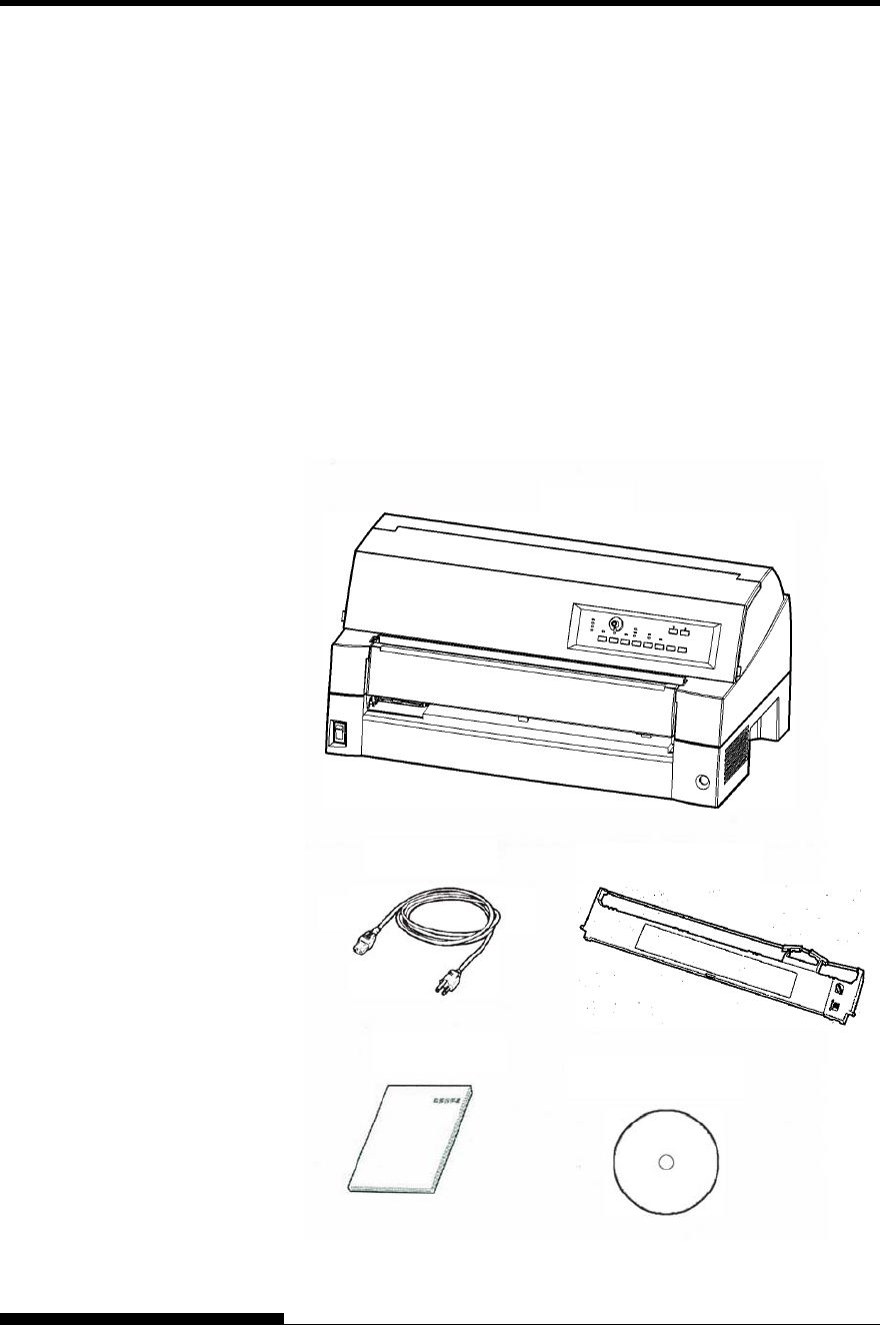
Unpack the printer as follows:
1. Open the carton and remove the printer and its components.
Make sure that you have all of the items shown below. Note that
the power cord supplied depends on the printer model (100-120
or 220-240 VAC power supply).
Checking items received
UNPACKING THE
PRINTER
Printer
Power cord Ribbon cassette
CD-ROM
Quick Guide
SETTING UP
User's Manual 2-3
2. Carefully examine each item for damage. Report any problems
to your dealer or shipping agent.
3. Place the printer where you plan to use it.
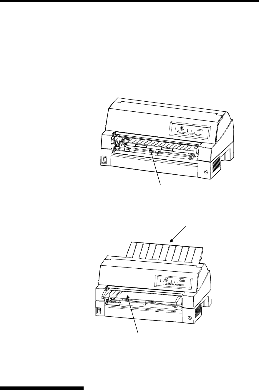
4. Remove the tapes and cushions securing the printer. Open the
front cover and remove the shipping restraint cardboard that
holds the print head carriage in place (shown below).
Removing the shipping restraint cardboard
5. Store the original shipping carton and packaging materials for
future use. For example, the original packaging is ideal for use
when you move or ship your printer to another location.
NOTE
The interface cable is not included with the printer. You must
purchase it separately. Connection of the interface cable is described
later in this chapter.

SETTING UP
2-4 User's Manual
Checking Options and Supplies
The following options and supplies, if ordered, are shipped separately:
• LAN card (option)
• Cut sheet feeder (option)
• Tractor unit (option)
• Small Paper Table (option)
• Large Stacker (option)
• Large Paper Table (option)
• Extra monochrome ribbon cartridges
Make sure that you received all the options you ordered. Installation of
options is described in Chapter 8.
Once you are sure you have everything, you are ready to assemble the
printer.
SETTING UP
User's Manual 2-5
This section explains how to handling the soundproof cover, changing
the tractor unit position and installing the ribbon cartridge.
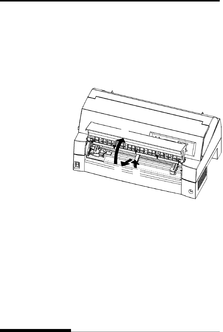
Handling the soundproof cover
You must open and close the soundproof cover when you operate the
front tractor.
1 Open the soundproof cover.
Slightly raise the front end of the front tractor cover (1), then pull (2)
and lift the table (3).
ASSEMBLING THE
PRINTER
(1)
(2)
(3)
SETTING UP
2-6 User's Manual
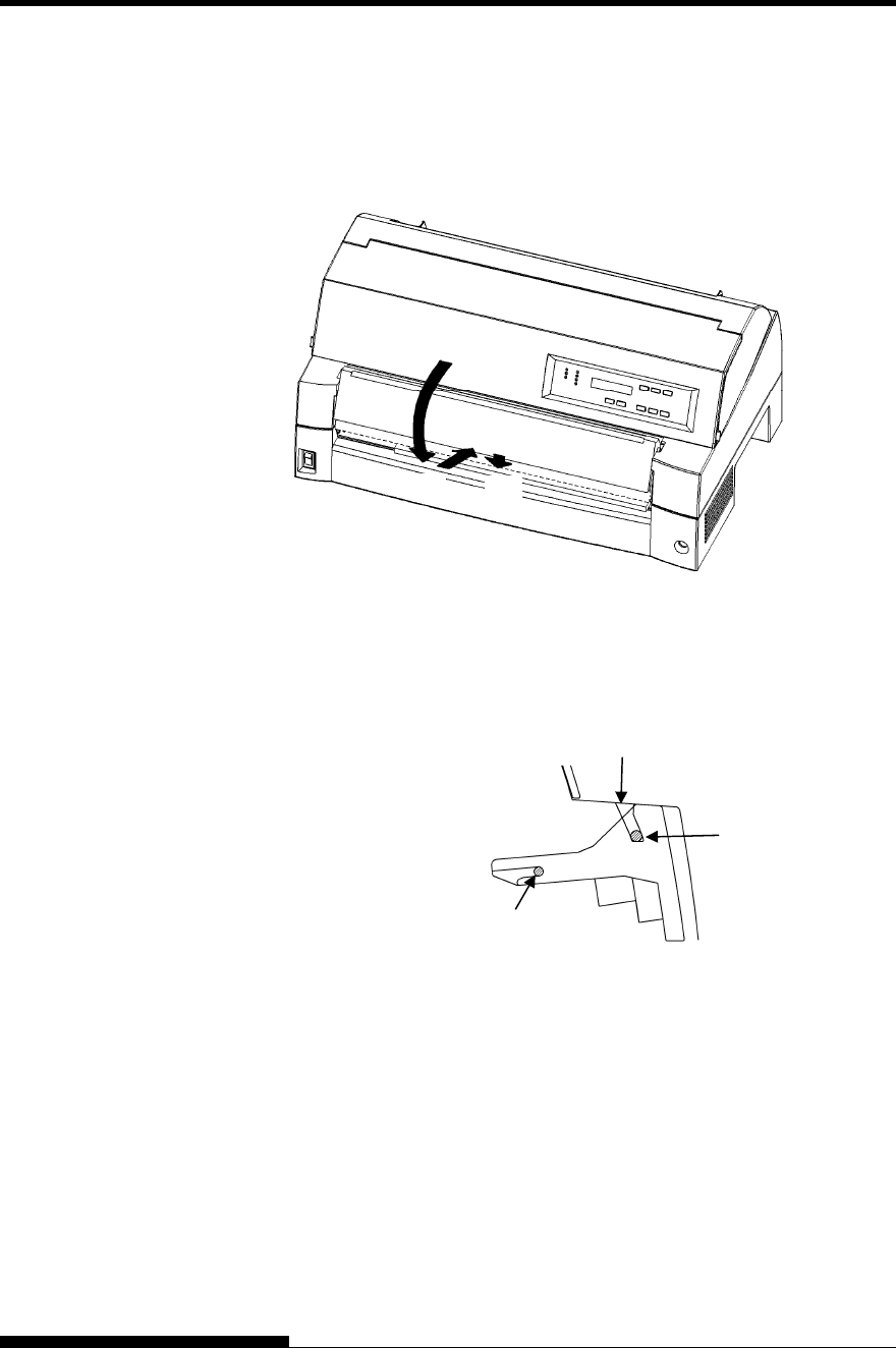
2 Close the sound proof cover.
Lower the soundproof cover as shown in the figure below (1), then
push (2) and close (3) the cover.
The complete setup conditions are shown below. Make sure that the top
end of the soundproof cover is engaged with the printer guide pin and the
guide pin on the soundproof cover is inserted into the cover groove.
NOTE
Do not apply unreasonable force while you are handling the
soundproof cover. It could cause damage. Also, do not leave the
soundproof cover in incomplete setting. Running the printer with
the soundproof cover left in incomplete conditions could cause a
paper jam.
Cover groove.
Guide pin (metal stud)
Soundproof cover guide pin
(3)
(1)
(2)
SETTING UP
User's Manual 2-7
Installing the Ribbon cartridge
(HOT)
CAUTION <HOT>
The print head and metal frame is hot during
printing or immediately after printing. Do not touch
them until it cools down.
1. Prepare the printer to install the ribbon cartridge.
Make sure that the print head protecting cardboard used for
transportation has been removed, then turn on the printer power with
the top cover closed. Ensure that the print head moves and stops at
the ribbon replacement position.
NOTE
If you turn on the printer power with the top cover open, the
print head does not move. Turn the printer power with the
top cover closed.
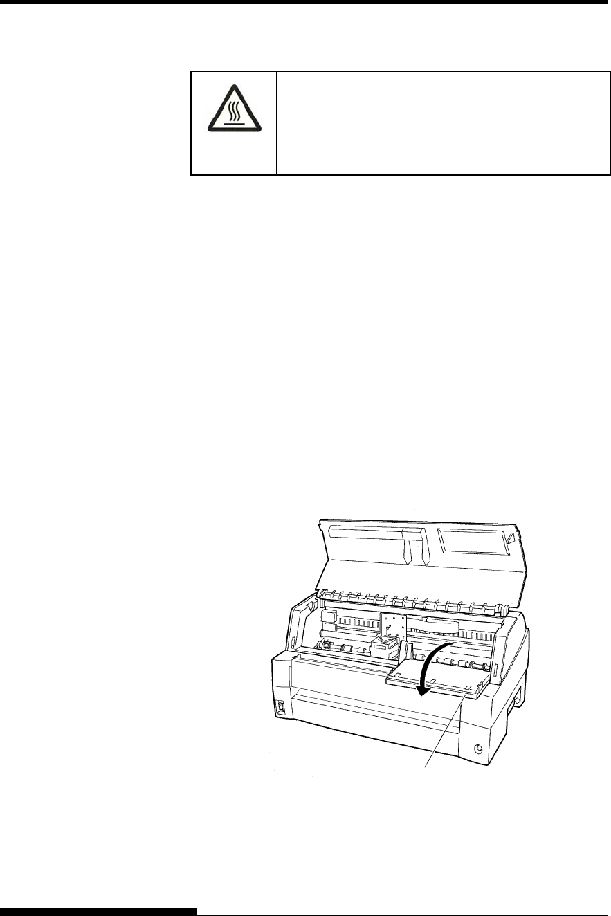
2. Turn off the printer power.
Make sure that the power switch is set to the “{” side.
3. Open the front cover of the printer. Slide the print head carriage so
that its center is at the position for replacing the ribbon cartridge
(indicated by the triangle marking on the front of the upper cover).
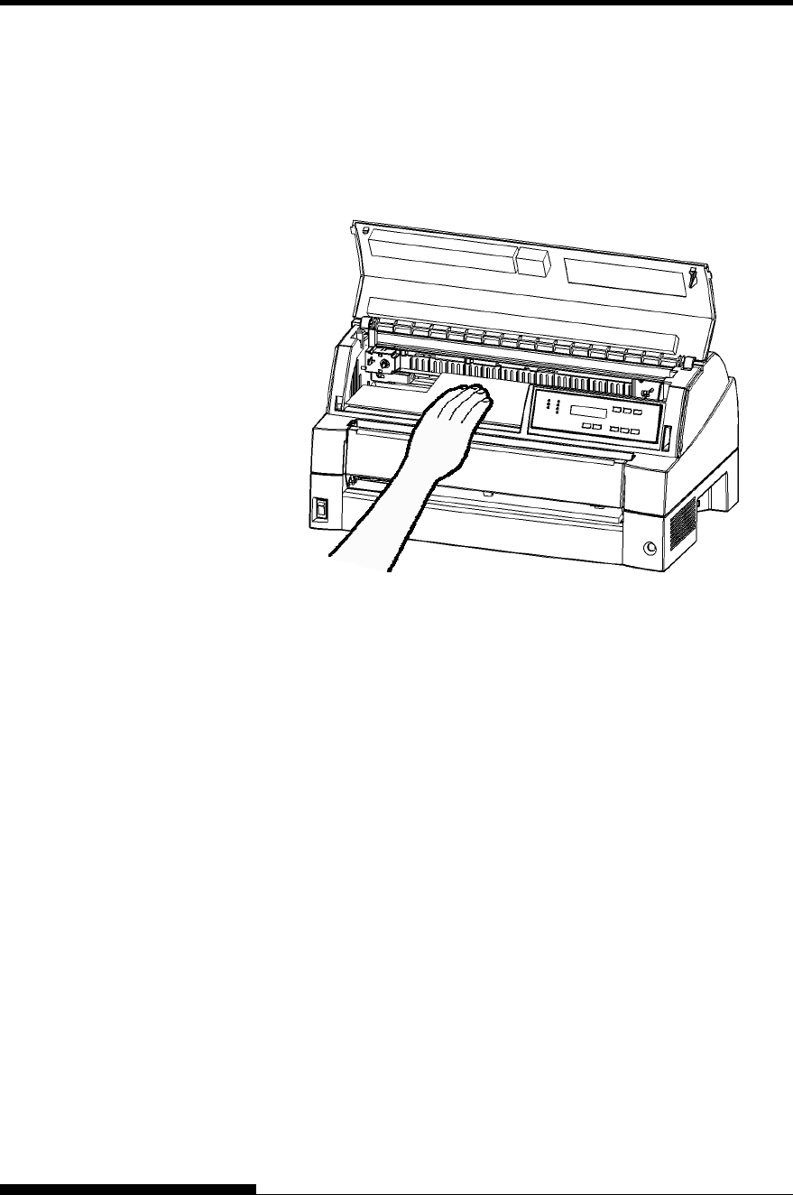
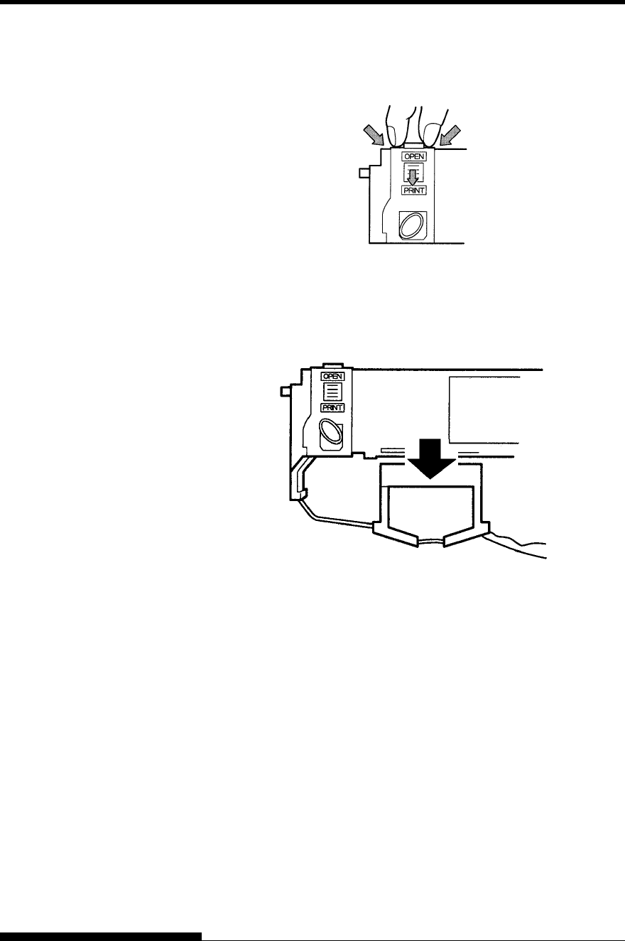
4. Open the control panel for easy installation of ribbon cassette.
Preparing the printer to install the ribbon cartridge
Control panel
SETTING UP
2-8 User's Manual
5. Remove the ribbon cassette from its package. Push in the two ribbon
release tabs. The tabs snap into the cassette and the ribbon feed
mechanism engages.
Preparing the ribbon cassette
6. Remove the ribbon guide (green part) from the ribbon cassette.
Don’t turn the ribbon feed knob before installation.
Preparing the ribbon cassette
SETTING UP
User's Manual 2-9
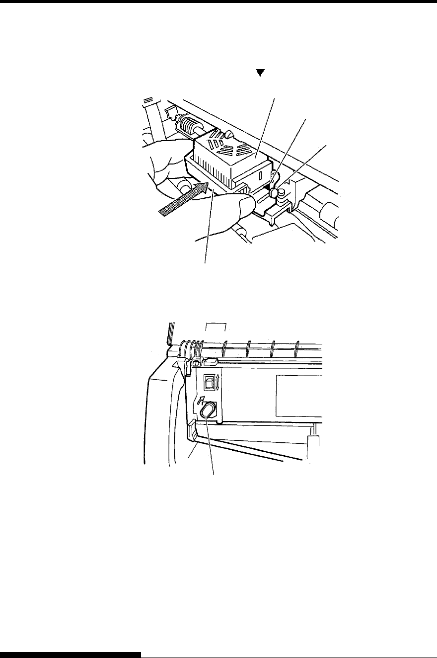
7. Put the green ribbon guide into the space in front of print head. And
then place the mounting pins (both side of ribbon cassette) on the
slot of the printer cover. And then push the ribbon cassette so that
the ribbon cassette is installed vertically.
Installing the ribbon cassette
Mounting pin
Mounting pin
Ribbon guide
Print head Space Slot Slot
Push the ribbon cassette until it
clicks.
SETTING UP
2-10 User's Manual
8. Attach the green ribbon guide on the print head.
Please make sure that the ribbon slack lightly. (If the ribbon is
strained, it will quirk when installation.)Push the green ribbon guide
until the triangle mark ” ”meets the round projection of print head.
9. Turn the ribbon feed knob clockwise to take up any slack in the
ribbon.
10. Return the control panel.
11. Close the front cover.
NOTE
A Fujitsu ribbon cassette is recommended. Don’t use other cassettes.
If other cassettes are used, operating problems or a damage of the
print head may be caused.
Triangle mark
Projections
Print Head
Ribbon Guide
Knob

SETTING UP
User's Manual 2-11
Selecting the Tractor Unit Position
NOTE
This printer uses a detachable tractor that can be used on either the
front or back of the printer. You can attach the tractor to either the
front or back of the printer according to your installation or
operating conditions. The printer is delivered to you with the tractor
attached to the front. You can detach it from the front and then
attach it to the back if needed.
See “SELECTING PAPER PATH” in Chapter 3.
SETTING UP
2-12 User's Manual
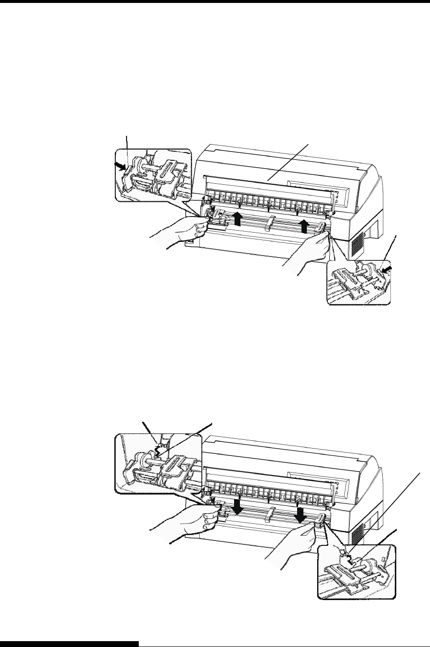
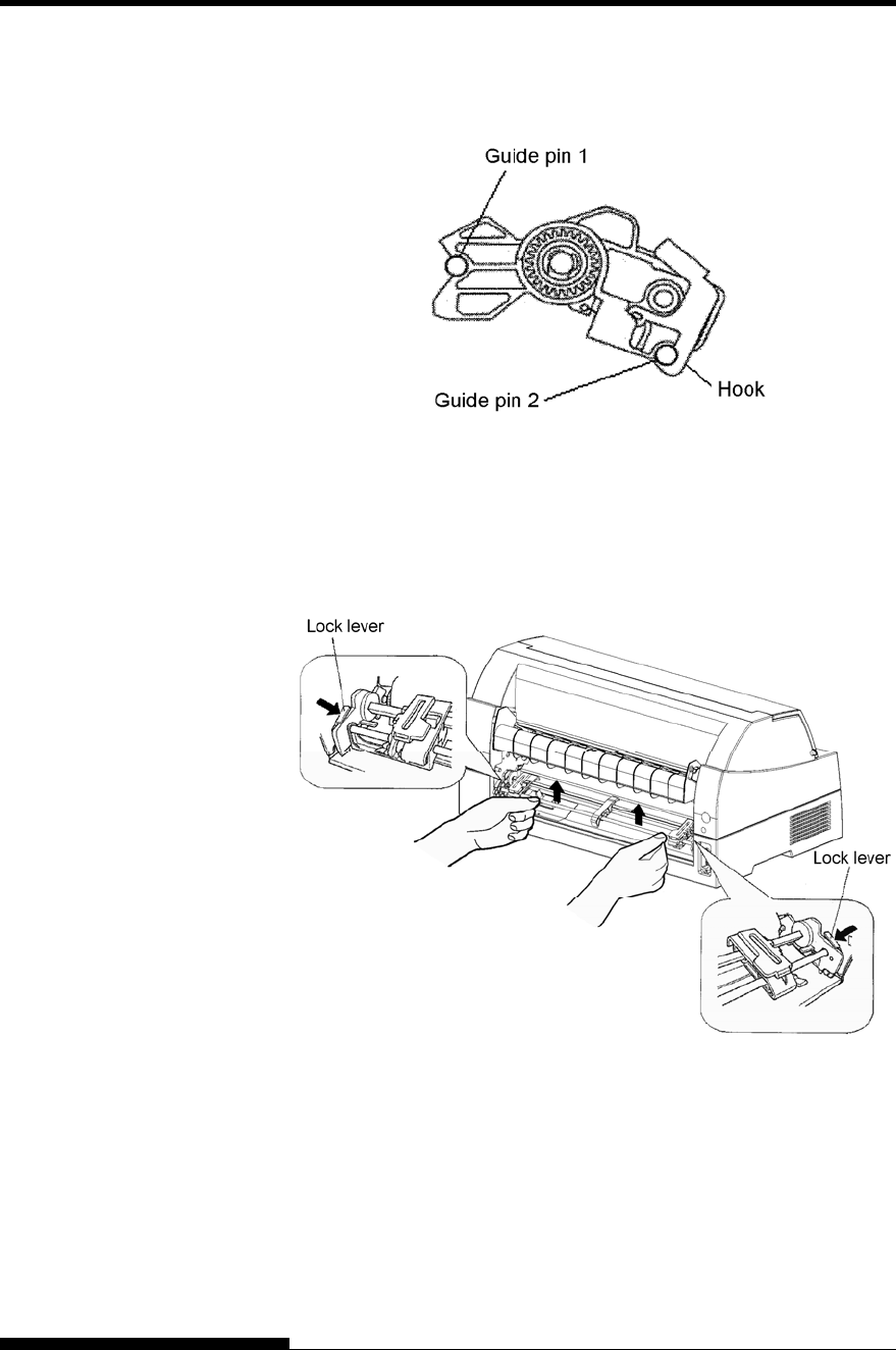
Mounting and removing the tractor unit
Tractor unit at the front
[Removing the tractor unit]
Raise the soundproof cover. While pressing the lock levers of the
tractor frames located on both sides of the tractor unit, lift out the
tractor unit to remove it.
[Mounting the tractor unit]
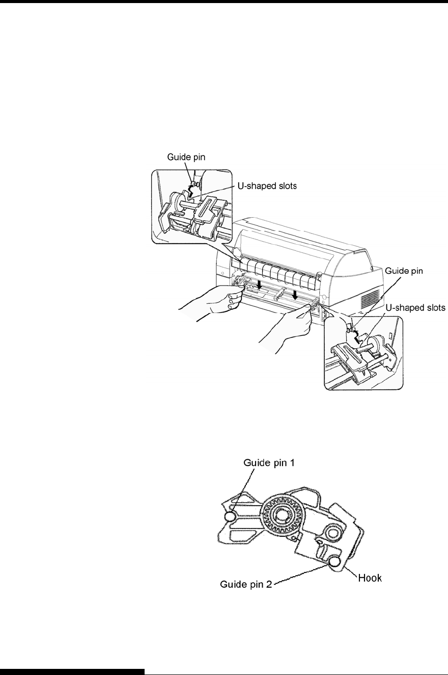
1) Position the U-shaped slots on both sides of the tractor unit over the
guide pins of the printer unit. (To set the tractor unit in position, line
it up with the groove of the left guide pin. The right guide pin has
no groove).
2) Push down the shaft at the front of the tractor unit until it locks with
an audible click. (Do not press the lock levers when pushing down
the shaft.)
Lock lever
Lock lever
Soundproof cover
Guide pin
U-shaped slot
U-shaped slot
Guide pin
SETTING UP
User's Manual 2-13
3) Verify that the hooks on both sides of the tractor unit are securely
hooked onto guide pin 2 as shown in the following figure.
Tractor unit at the rear
[Removing the tractor unit]
While pressing the lock levers of the tractor frames located on both
sides of the tractor unit, lift out the tractor unit to remove it.
SETTING UP
2-14 User's Manual
[Mounting the tractor unit]
1) Position the U-shaped slots on both sides of the tractor unit over
the guide pins of the printer unit. (To set the tractor unit in
position, line it up with the groove of the left guide pin. The
right guide pin has no groove).
2) Push down the shaft at the front of the tractor unit until it locks
with an audible click. (Do not press the lock levers when
pushing down the shaft.)
3) Verify that the hooks on both sides of the tractor unit are
securely hooked onto guide pin 2 as shown in the following
figure.
SETTING UP
User's Manual 2-15
Now that your printer is assembled, take a moment to become familiar
with its major parts.
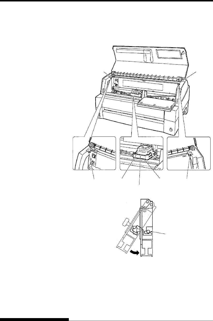
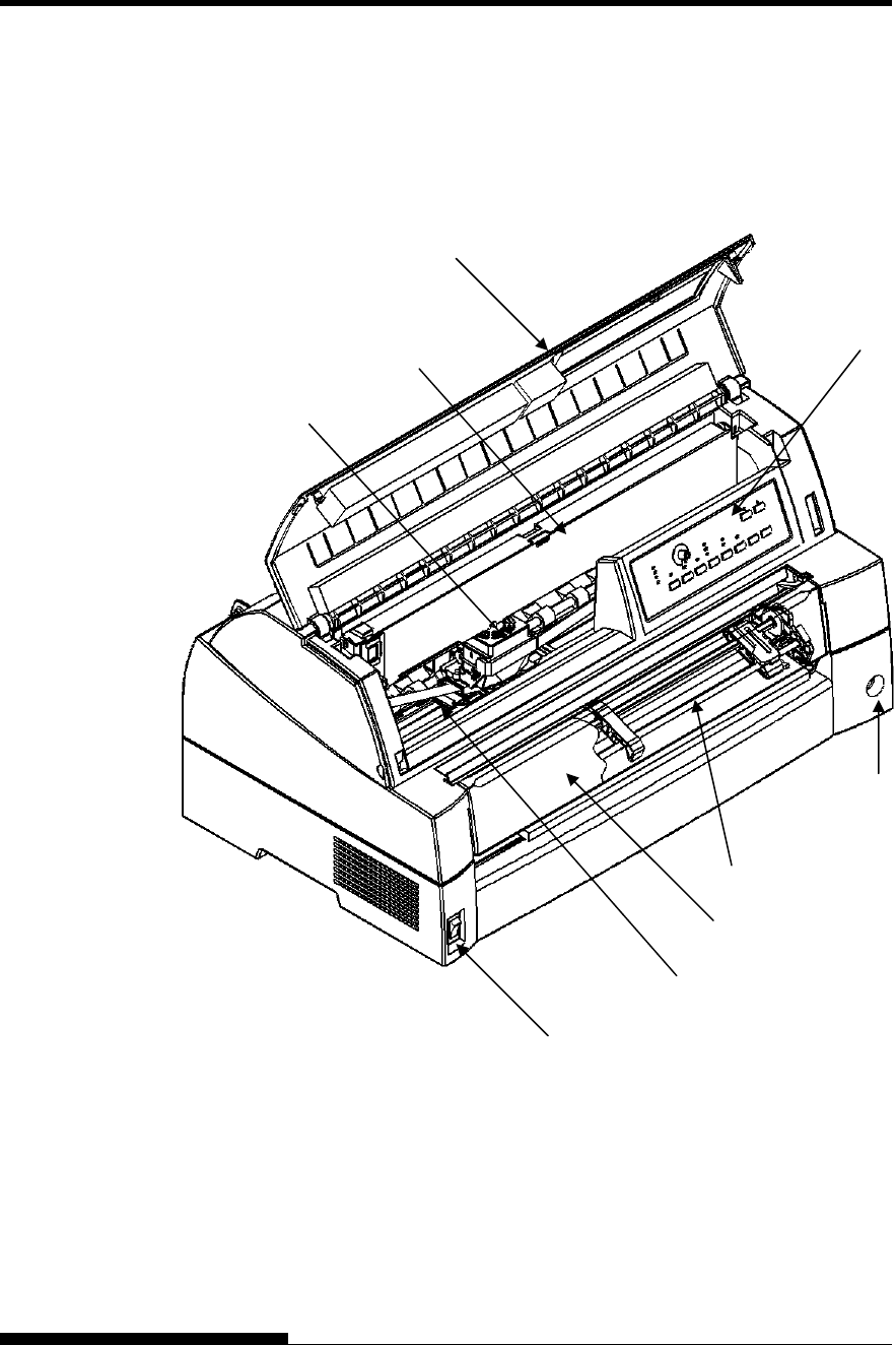
Looking at the printer from the front left side and rear right side, you can
see the parts of the printer shown in the figure below.
Printer components (front)
The printer control panel has the buttons and indicators used to load and
feed paper (see Chapter 3) and select print features (see Chapter 4). The
control panel also allows you to change the printer’s optional settings
(see Chapter 5).
GETTING
ACQUAINTED WITH
YOUR PRINTER
Soundproof cover
Tractor unit
Front cover
Ribbon cassette Control Panel
Power Switch
Front CSF connector
Print Head
Card Guide
(Aluminum print guide)
SETTING UP
2-16 User's Manual
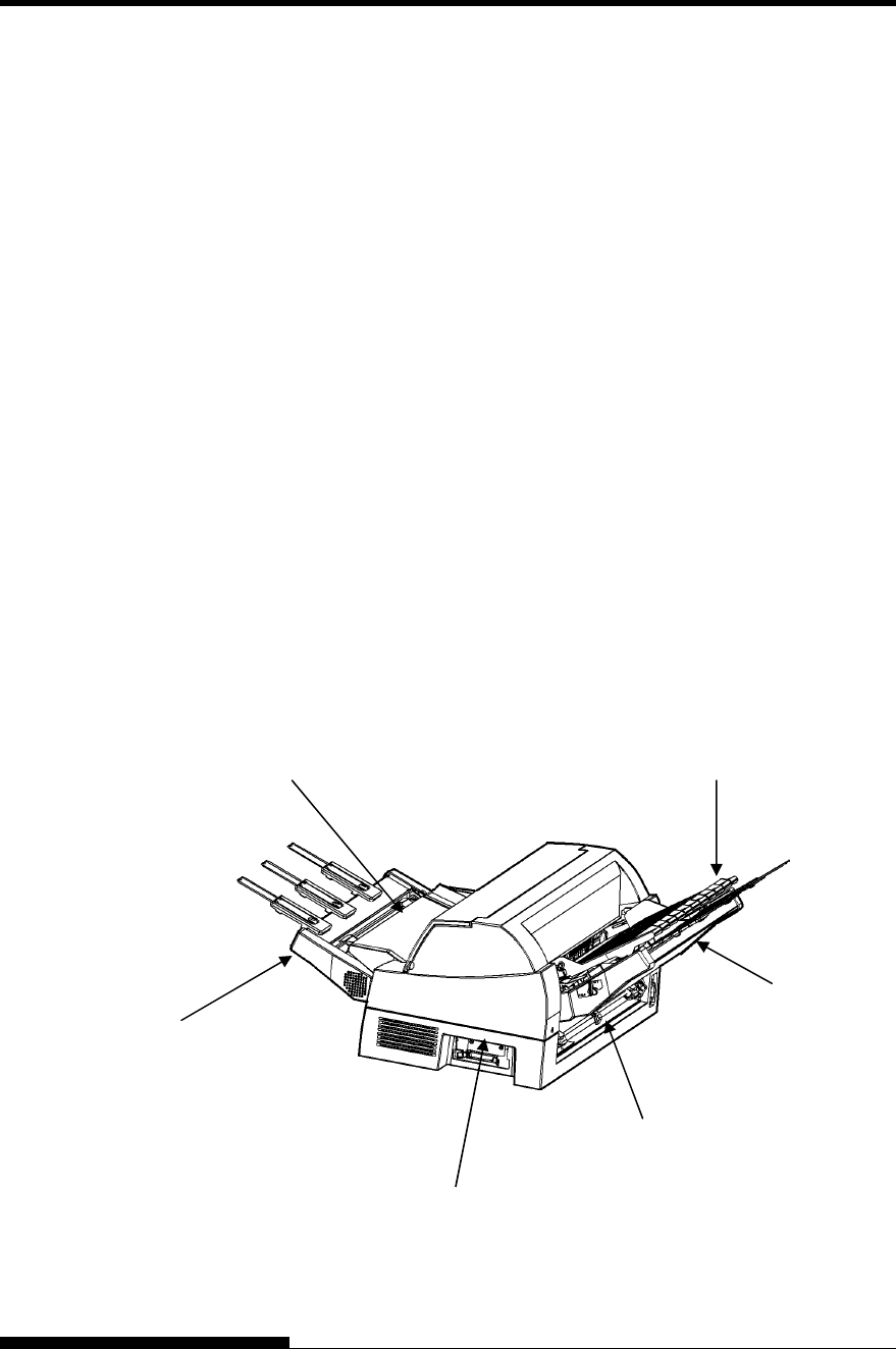
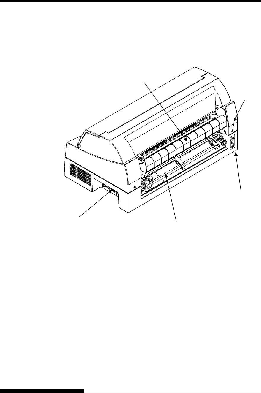
Printer components (rear)
Tractor unit (option).
Power Connector
Rear stacker
Rear CSF connector
INF connector
SETTING UP
User's Manual 2-17
Before you plug in the printer:
9 Make sure that the printer power is switched off. The side
marked “{” on the power switch should be depressed.
9 Make sure that the power outlet is properly grounded.
9 Make sure that you use the power cord shipped with the printer.
This cord is designed to minimize radio frequency interference.
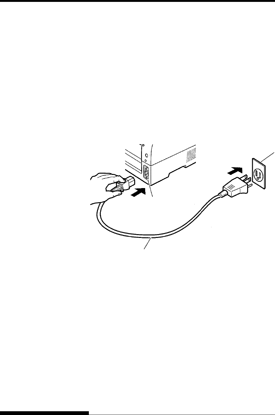
To plug in the power cord:
1. Plug one end of the power cord into the power connector on the
rear of the printer.
2. Plug the other end of the power cord into the power outlet.
Connecting the power cord
3. Make sure that the power cord is securely connected.
4. Turn on the power by pressing the side marked “I” on the power
switch. The POWER indicator on the printer control panel will
light, the print head will move to its home position within a few
seconds, and the ONLINE indicator will light (green).
NOTE
If no forms are loaded, the printer beeps and the red PAPER OUT
indicator lights and the ONLINE indicator will not light.
CONNECTING THE
POWER CORD
Power connector
Power cord
Power outlet
SETTING UP
2-18 User's Manual
At this point, load paper and run the printer self-test. The self-test checks
printer performance and print quality before you connect the printer to
the computer.
Loading Paper for the Self-Test
To print the self-test, load continuous form wider than 254 mm (10
inches) and set the left tractor so that the left end of continuous form
may suit “0-10mm” of a scale (see Chapter 3).
Printing the Self-Test
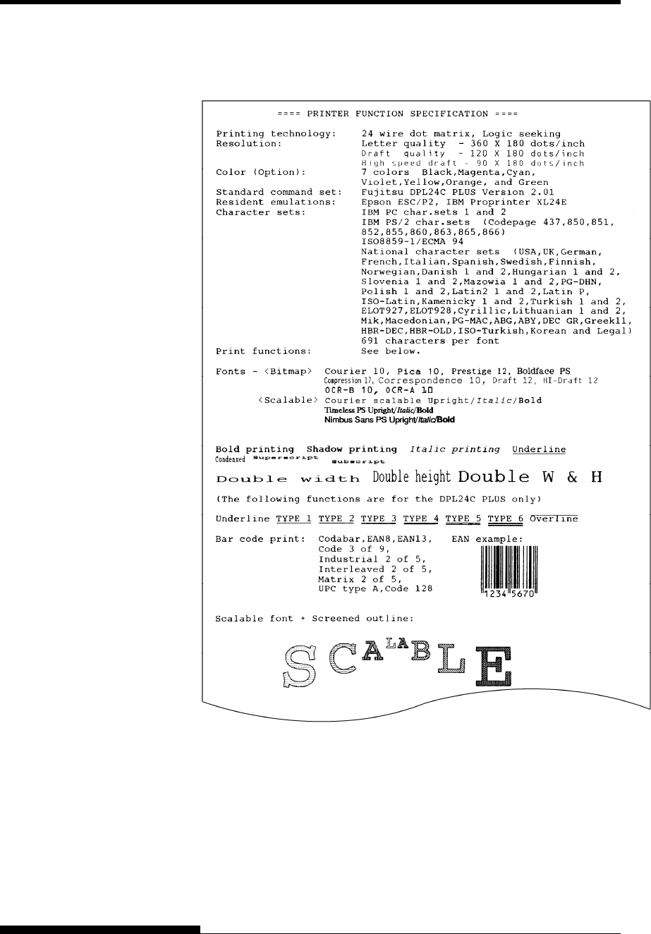
The printer has a built-in self-test program. The self-test prints the
firmware version, the names of the printer’s resident emulations, and all
of the characters available in the emulations. The self-test prints 80
characters per line.
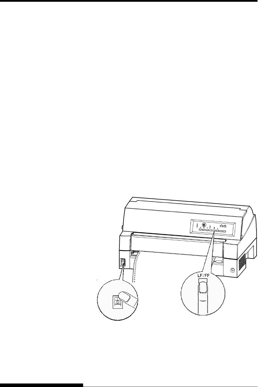
To print a self-test page, make sure that continuous forms are loaded.
Then proceed as follows:
1. Turn the printer off.
2. While pressing the LF/FF button, turn the printer back on.
Keep the LF/FF button pressed until the printer beeps.
Self-test printing will start.
Starting the self-test
3. Allow printing to continue for a dozen or more lines of repeat
printing. To exit the self-test mode, press the ONLINE button.
To remove the test page refer to Chapter 3.
TESTING THE
PRINTER (OFFLINE)
SETTING UP
User's Manual 2-19
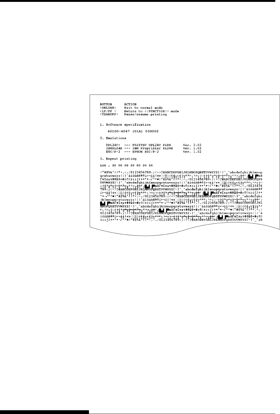
4. Examine the self-test page. It should look like the sample on the
below.
Check that printing is uniform and that there are no light, dark,
or smudged areas. If the print quality is good, go to step 5.
Otherwise, try to correct the problem as follows:
• Make sure that the ribbon is installed correctly.
• Load a new sheet of paper.
• Repeat the self-test procedure.
Sample self-test page
5. To exit the self-test mode, press the ONLINE button. The
printer will return online.
NOTE
The printer can also print a special “demo pattern” that illustrates
some of the printer’s capabilities. To print the demo pattern:
1. Load continuous forms (wider than 254 mm (10 inches)).
2. Turn the printer off .
3. While pressing the FRONT DIR button, turn the printer back
on.
The printer will start printing the demo pattern.
4. The demo pattern stops printing after one page. To pause or
restart the demo during printing of a page, press the ONLINE
button.
SETTING UP
2-20 User's Manual
5. To exit demo mode, turn the printer off.
Demo pattern

SETTING UP
User's Manual 2-21
Your printer supports one of the following interface options:
• Centronics parallel interface+RS-232C serial interface
• Centronics parallel interface+USB (+LAN) interface
The parallel interface connector has wire clips. The serial interface
connector has tapped holes. Cables for these interfaces are available from
dealers, cable manufacturers, and other suppliers.
The LAN card is a user installable option. For details, see Chapter 8 or
refer to the Online Manual that comes with the LAN card.
For detailed interface specifications, see Appendix D.
Selecting a Parallel Interface Cable
For the parallel interface, use a cable that meets the following
specifications:
9 At the printer end, use a shielded male Centronics connector,
such as an Amphenol DDK 57FE-30360 or its equivalent. To
prevent RFI (radio frequency interference), the connector cover
must be connected to the cable shield.
9 Make sure that the cable length does not exceed 3 meters (10
feet).
Selecting a Serial Interface Cable
For the serial interface, use a cable that meets the following
specifications:
9 At the printer end, use a 25-pin male connector, such as a
Cannon DB-25P or its equivalent.
9 To determine the type of connector your computer requires,
refer to your computer user manual or ask your dealer.
9 The cable length can be up to 15 meters (50 feet). This type of
length is required in many networking and shared-printer
configurations.
CONNECTING THE
PRINTER TO YOUR
COMPUTER

SETTING UP
2-22 User's Manual
Selecting a USB Cable
9 When the USB interface is used to connect to the host computer,
the parallel interface and the serial interface (factory add-on
option) cannot be connected simultaneously.
9 The USB interface does not guarantee all connections of USB-
supported devices.
Selecting a LAN cable
9 When the LAN cable is connected, the parallel and USB cables
cannot be used.
9 The LAN cable, when used in 100BASE-TX environments,
must conform to category 5 or higher.
Connecting the Interface Cable
To connect the interface cable:
1. Turn off both the printer and the computer.
2. Attach the interface cable to the connector. Do not connect more
than one interface cable type to the printer at the same time.
Connecting the interface cable
RS232C Serial connector

SETTING UP
User's Manual 2-23
NOTE
The LAN interface is a user add-on option.
When installing a LAN card, remove the two screws securing the
cover and remove the cover. Then insert the LAN card and reattach
the cover with the two screws removed earlier. For details, refer to
the Online Manual that comes with the LAN card.
3. To secure a parallel interface cable, flip the fastener clips
located on the printer into the notches on the cable connector.
To secure a serial interface cable, tighten the screws in the cable
connector.
4. Attach the other end of the interface cable to your computer.
Gently pull on the cable to verify that it is secure.
Before printing with your software, verify that the correct emulation is
selected on your printer. This section describes the available emulations
and their selection.
For Experienced Users:
The printer’s preselected factory setting is the Fujitsu DPL24C PLUS
emulation. If this emulation is acceptable, you may skip this section.
An emulation is a set of commands used by your software to
communicate with the printer. There are many different emulations
available for printers.
Each emulation has unique features and capabilities. This printer offers
three resident emulations:
• Fujitsu DPL24C PLUS (for Fujitsu DL-series printers)
• IBM Proprinter XL24E
• Epson ESC/P2
Resident emulations are stored in the printer’s permanent memory.
Here are some points to help you determine which emulation to select:
9 Determine which emulations your software supports. (Refer to
your software documentation.) Since most software programs
support this printer, try to run a program with the factory default
emulation first.
(DPL24C PLUS emulation is the factory default.) Try this
emulation even if you are not sure of which emulation to choose.
See Chapter 5 for detailed information about how your printer
communicates with your software.
SELECTING AN
EMULATION
SETTING UP
2-24 User's Manual
9 If you are using more than one software package, determine
which emulation is supported by the software you use most
frequently.
Select that emulation.
9 If your software supports more than one emulation, select the
DPL24C PLUS emulation if possible. This emulation has the
greatest capabilities.
9 If you want to use an emulation that is not supported by your
software, contact your software manufacturer or printer dealer
and ask whether support is available. You may be able to obtain
a printer driver that is not shipped with the original software
package.
To select an emulation, proceed as follows(LED):
1. Turn the printer on and load continues forms.
To print the “OFFLINE SET UP MODE”, load continuous form
wider than 254 mm (10 inches) and set the left tractor so that the
left end of continuous form may suit “0-10mm” of a scale (see
Chapter 3).
2. Enter setup mode.(LED)
Press the ONLINE button to place the printer offline. Then,
press the setup buttons (AUTO GAP and HI IMPACT).
As the printer enters offline setup mode, it prints the following
information:
NOTE
If LCD type control panel. Please refer to Chapter 5.
OFF
SETTING UP
User's Manual 2-25
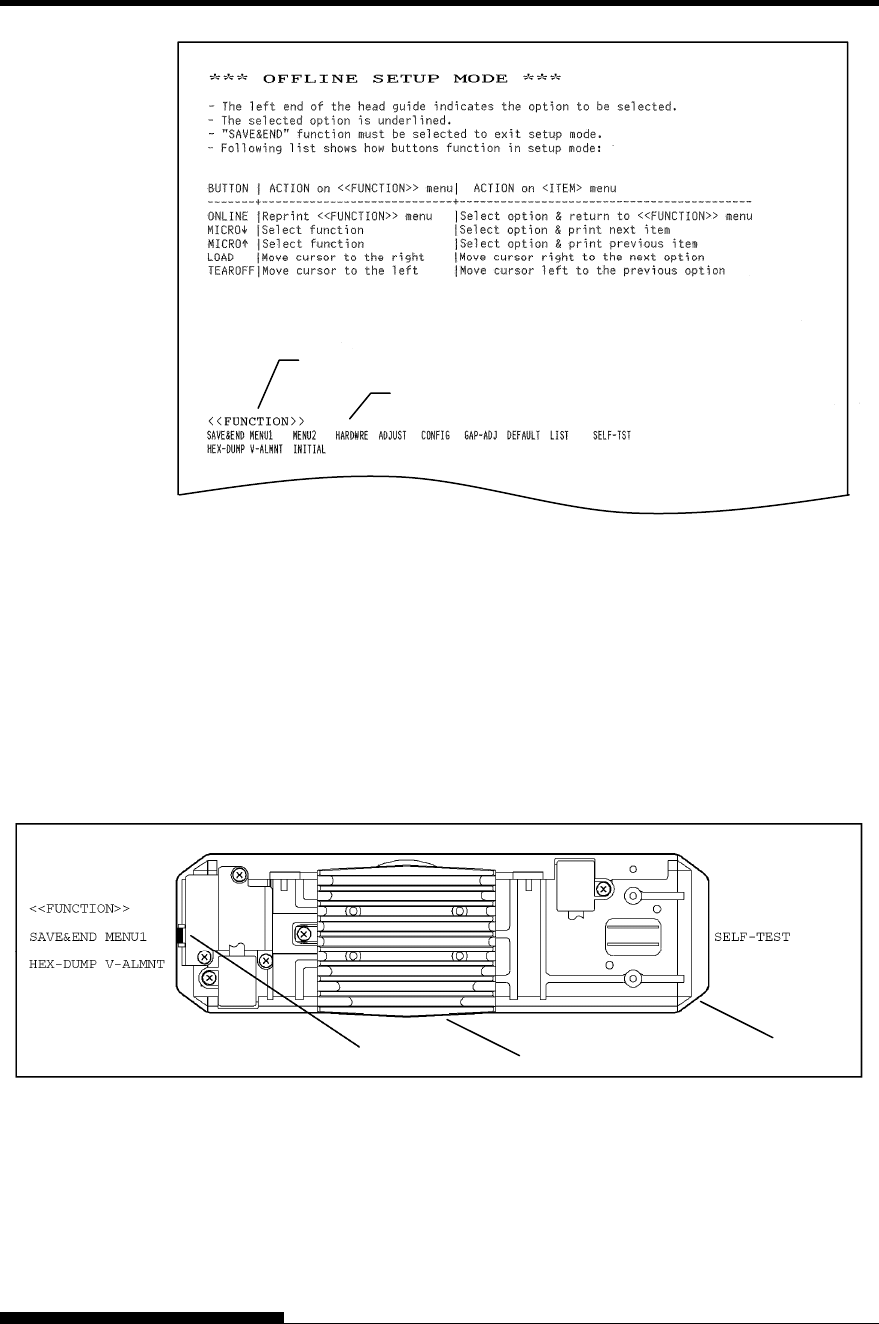
Initial printout in setup mode
Check that the <<FUNCTION>> menu is printed at the bottom
of the page.
3. Select the MENU1 function.(LED)
Locate the cursor on left edge of the Card guide (aluminum
print guide). Initially, this cursor should be positioned at SAVE
& END at the beginning of the <<FUNCTION>> menu. Press
the LOAD button repeatedly to position the cursor at MENU1,
as shown below:
<<FUNCTION>> menu
Function
The cursor Card guide Print head

SETTING UP
2-26 User's Manual
Press the MICRO FEED button to select MENU1 and print
the following <EMULATE> options:
<EMULATE> DPL24C+ XL24E ESC/P2
The currently selected emulation is indicated by a short
underline. In the figure shown above, the Fujitsu DPL24C
PLUS emulation is selected.
4. Select an emulation.(LED)
Press the LOAD button repeatedly to position the cursor at the
required emulation. Press the MICRO FEED button to select
the emulation and print the next MENU1 item.
5. Exit MENU1.(LED)
Press the ONLINE button to exit the MENU1 function and
reprint the <<FUNCTION>> menu.
6. Exit setup mode to save the emulation.(LED)
To exit setup mode and save the new emulation, make sure that
the cursor is positioned under SAVE & END. Then press the
MICRO FEED button. The printer selects SAVE & END and
then goes online.
To change other printer settings using the printer setup mode, see
Chapter 5.
Once the self-test verifies that the printer is functioning correctly, try
printing using one of your software packages. This exercise will ensure
that the printer is correctly connected to your computer.
If you are using a parallel interface, the printer usually prints the correct
characters automatically. However, you may need to adjust the page
layout or various print features using your software or the printer setup
mode. If you are using a serial interface, the printer may not work at all
or it may print a lot of “?” characters. In this case, the serial settings on
the printer do not match those of your computer or your software. Before
changing any settings, use the procedure described below to try printing
using the printer’s preselected factory settings.
Test communication between the printer and computer as follows:
1. Load continuous forms.
2. Check that the printer is online. If the ONLINE indicator is not
green, press the ONLINE button.
3. Try to print using your word processor, a programming
language, or other software.
PRINTING A
SAMPLE PAGE
(ONLINE)

SETTING UP
User's Manual 2-27
4. Use your software printer selection menus or the printer setup
mode (described in Chapter 5) to make required changes in the
page layout or other print features.
If the printer does not print or prints the wrong characters,
proceed as follows:
• Make sure that the interface cable is properly connected.
• Make sure that the printer emulation selected in your
software is the same as that selected on the printer.
• If you are using a serial interface, make sure that the printer
serial interface settings are the same as those on the
computer. The printer’s preselected factory settings are 8
data bits, no parity, 1 stop bit, 9600 baud, and XON/XOFF
protocol.
You can change the serial settings on either the printer or
your computer. To change the printer settings, see Chapter
5. To change the computer settings, use the selection menus
provided by your software or the commands of your
computer operating system.
The following example uses the MS-DOS operating
system:

SETTING UP
2-28 User's Manual
Using MS-DOS to Specify Serial Interface Settings
For an IBM PC or compatible device, use the following MS-DOS
MODE commands to set the computer serial settings to match the
printer factory settings:
MODE COM1:9600,N,8,1,P
MODE LPT1:=COM1
To activate these settings whenever you turn the computer on, write the
MODE commands in your AUTOEXEC.BAT file. Make sure that the
MODE.COM file is included in your root directory.
If the printer still doesn’t work, consult your dealer or
someone experienced in serial interface communications.
• If an error occurs during printing with Windows, simply
printing the page again will cause the printed characters to
be garbled. To avoid this problem, execute reset from the
control panel or turn off the printer, then print the page
again.
You are now finished setting up and testing the printer. To familiarize
yourself with everyday printer operations, such as loading paper,
selecting print features, and printing, see Chapters 3 and 4.
A printer driver is required for using the printer in a Windows
environment. Special printer drivers for Windows 95, 98, Me, NT 4.0,
2000, XP, and Server 2003 are provided with the DL7600 printer.
For information about how to install printer drivers, refer to Readme.txt
of the printer driver to be installed.
- These printer drivers run with DLP24C+ emulation. Be sure to
specify DLP24C+ emulation for the printer mode.
- The DL7600 printer driver is a printer driver for monochrome
printing.
The color data printing result may differ from its print preview
or the monochrome data printing result.
INSTALLING THE
PRINTER DRIVER
User's Manual 3-1
3
CHAPTER 3 PAPER HANDLING
PAPER HANDLING
This chapter explains how your printer uses paper.
Topics covered are:
• Selecting paper
• Overview of paper operations
• Selecting the paper path
• Adjusting for paper thickness
• Using continuous forms (front-tractor feed and rear-tractor feed)
• Using single sheets
• Feeding and positioning paper
• Switching paper types
Tips for paper handling are given at the end of this chapter. Check that
section if you are using multipart forms, envelopes, or labels.
The printer can handle either single sheets or continuous forms. Single
sheets, also called cut sheets, include envelopes and noncontinuous,
multipart forms. Continuous forms include labels and multipart forms fed
into the printer using the forms tractors.
For best results, use paper that meets the specifications listed below.
(See Appendix B for detailed specifications.) If you are unsure of the
suitability of a particular paper, try testing the paper or consult your
dealer.
Length Single sheets: 70 to 420 mm (3 to 16.5 in)
Continuous forms: 102 mm (4 in) or greater
Width Single sheets: 55 to 420 mm (2.16 to 16.5 in)
Continuous forms: 102 to 420 mm (4 to 16.5 in)
Thickness 0.65 mm (0.026 in) maximum total thickness.
Copies 1 to 8-copies (Paper table/Front/Rear tractor)
1 to 5-copies (Cut sheet feeder)
Note:
To use cut sheets the optional large or small cut sheet table is
required.
SELECTING PAPER
PAPER HANDLING
3-2 User's Manual
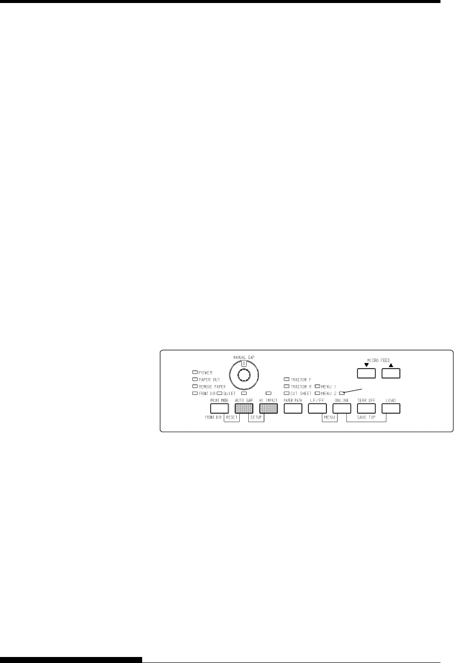
The following buttons are used in paper handling:
• LF/FF, TEAR OFF, PAPER PATH, MICRO FEED,
MICRO FEED and LOAD buttons on the control panel
(A different function is enabled when each button is pressed in
conjunction with the ONLINE button.)
The following figure shows the location of each button:
Location of the buttons
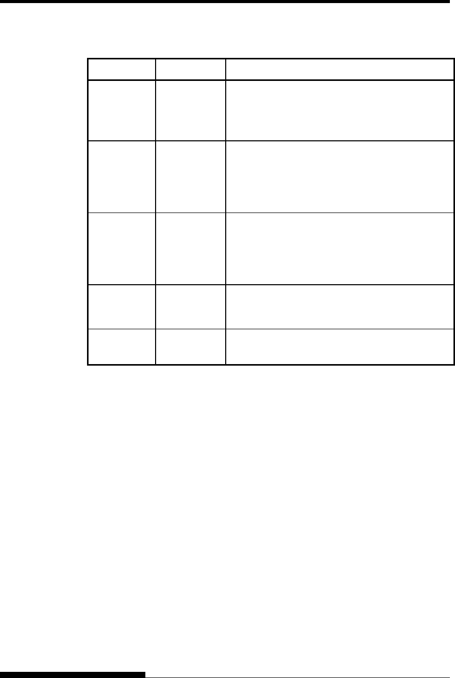
Table 3.1 summarizes the use of buttons in paper handling. More detailed
information is provided later in this chapter.
NOTE
To load or feed paper, the printer must be:
• Online but not receiving or printing data
• Offline but not in setup mode
To micro feed paper, the printer must be:
• Online but not receiving or printing data
• Offline but not in setup mode
OVERVIEW OF
PAPER
OPERATIONS
PAPER HANDLING
User's Manual 3-3
Table 3.1 Buttons Used for Paper Handling
Button/Dial Purpose Action
ONLINE Change the
printer mode
Stop/resume
printing
Press ONLINE to place the printer online or offline.
Press ONLINE to stop or resume printing.
LOAD Load/unload
paper
Save adjusted
load point
Press LOAD to load paper or to retract continuous
forms to the “park position.”
Press LOAD and ONLINE simultaneously to
permanently store a load position adjusted by micro
feeding immediately after loading paper.
LF/FF Form feed
Line feed
Press and hold LF/FF to execute a form feed.
Continuous forms are fed forward by one page.
Single sheets are ejected.
Press LF/FF within three seconds to feed paper
forward by one line.
TEAR OFF Advance
forms for
tear-off
Press TEAR OFF to advance the forms perforation
to the tear-off edge. Tear off the forms, then press
any button to retract the remaining forms.
PAPER
PATH
Selects paper
path
Press PAPER PATH to select the paper path: front
tractor, rear tractor, cut sheet.
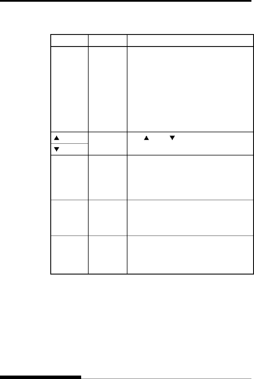
PAPER HANDLING
3-4 User's Manual
Table 3.1 Buttons Used for Paper Handling (Cont.)
Button/Dial Purpose Action
PRINT
MODE/
FRONT DIR
Select cut
sheet ejection
Press PRINT MODE/FRONT DIR at Offline to
select a direction of ejecting cut sheet.
• Front ejection – FRONT indicator lights. It
blinks when paper is ejected to
the paper table prompting the
user to remove the paper.
• Rear ejection – FRONT indicator does not
light.
When you save your setting in the setup mode, it
becomes the new default. The default setting is
invoked whenever you turn on the printer.
MICRO
MICRO
Micro Feed Press MICRO/ MICRO to feed paper by 1/180
inch in the direction of the arrow.
(LED)
AUTO GAP
Select paper
thickness
control mode
Select paper thickness control mode.
AUTO GAP — AUTO GAP indicator lights.
Manual Gap — AUTO GAP indicator doesn't
lights.
The Manual Gap dial is enabled.
(LED)
MANUAL
GAP DIAL
Select paper
Thickness at
MANUAL
MODE
Select the paper thickness at MANUAL MODE.
Auto Gap is usually used. Auto Gap is used for
printing on paper of different thicknesses.
(LCD)
GAP
ADJUST
Select paper
Thickness
Select the paper thickness as follows.
AUTO,GAP-1,・・・・・・・,GAP-9,GAP-A,・・,GAP-D
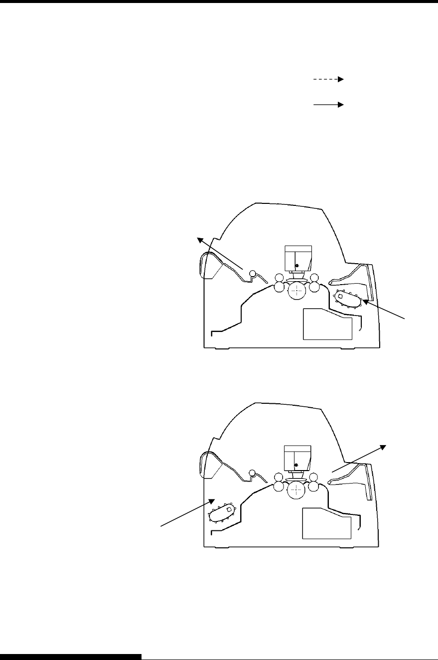
PAPER HANDLING
User's Manual 3-5
This printer has a variety of paper paths and feed directions.
Paper Paths and Feed Directions
See the following five cases. : Cut sheet
: Continuous forms
(n) : Input
[n] : Output
With front tractor
(1) Front tractor → Print → Rear eject
With rear tractor
(2) Rear tractor → Print → Front eject
SELECTING PAPER
PATH
(1)
[1]
(2)
[2]
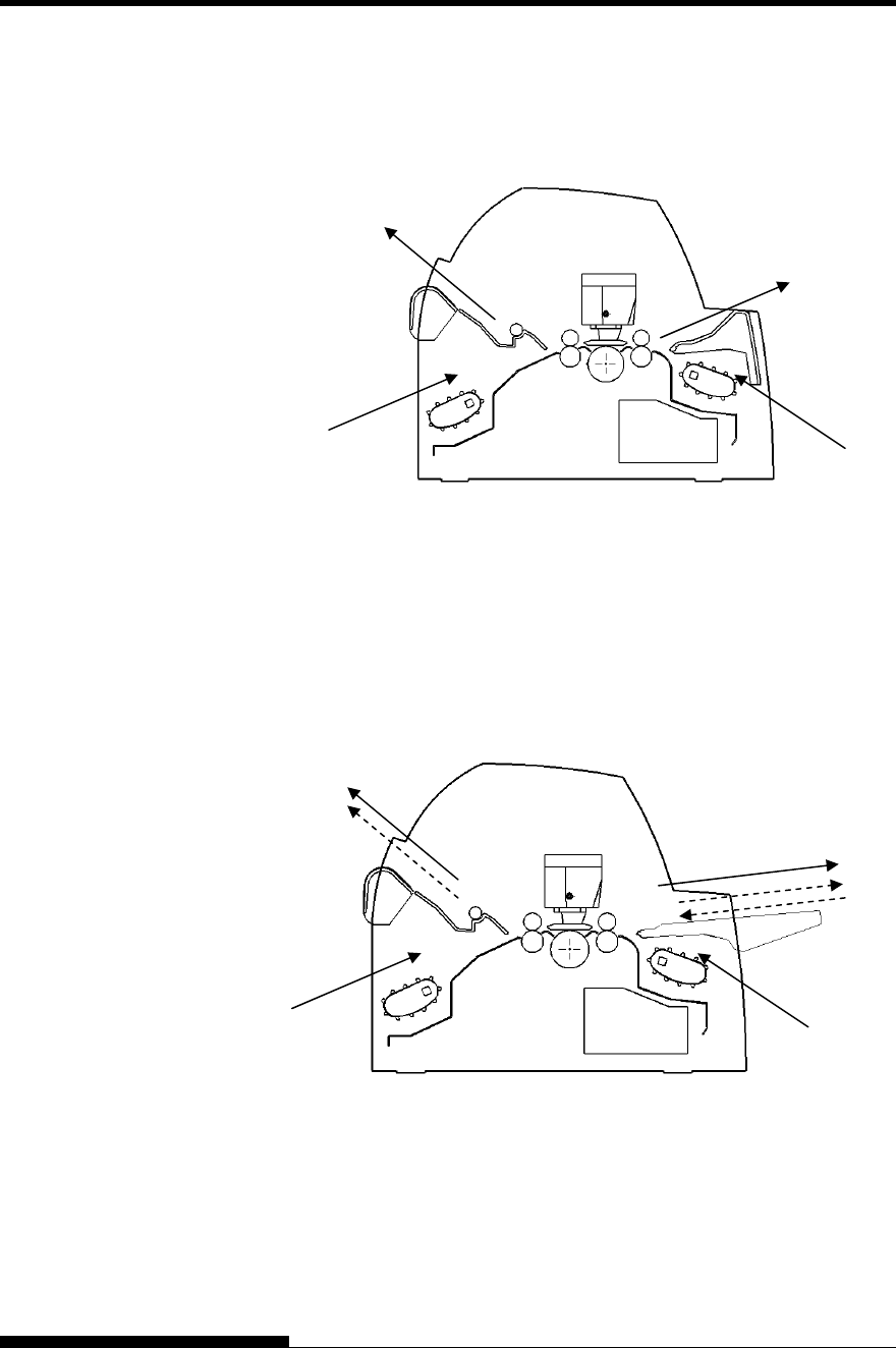
PAPER HANDLING
3-6 User's Manual
With front and rear tractors (either optional)
(1) Front tractor → Print → Rear eject
(2) Rear tractor → Print → Front eject
With front and rear tractors (either optional) and Large
paper table (optional)
(1) Front tractor → Print → Rear eject
(2) Rear tractor → Print → Front eject
(3) Paper table → Print → Paper table
(4) Paper table → Print → Rear stacker
Note
Large and small paper table are available as option.
(1)
(2)
[2]
[3]
(1)
(2)
[2]
[1]
[3]
(3)(4)
[4]
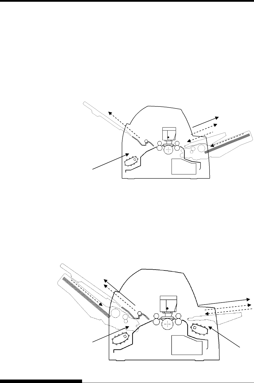
PAPER HANDLING
User's Manual 3-7
In the next two cases, the number of cut sheets stacked in the printer may
be reduced depending on printing conditions and environments. Follow
the notes.
With rear tractor and front optional cut sheet feeder and
large stacker(optional) and large paper table(optional).
(2) Rear tractor → Print → Front eject
(3) Paper table → Print → Paper table
(4) Paper table → Print → Rear stacker
(5) Front cut sheet feeder → Print → Paper table
(6) Front cut sheet feeder → Print → Rear stacker
With front or rear tractor (either optional)and rear optional cut sheet
feeder and large stacker(optional) and large paper table(optional).
In addition, the front and rear tractor (either is optional) can be mounted.
(1) Front tractor → Print → Rear eject
(2) Rear tractor → Print → Front eject
(3) Paper table → Print → Paper table
(4) Paper table → Print → Rear stacker
(7) Rear cut sheet feeder → Print → Paper table
(8) Rear cut sheet feeder → Print → Rear stacker
(5)(6)
(2)
[2]
[
3
]
[
5
]
(3)(4)
[4] [6]
(1)
(2)
[2]
[1]
[3][7]
(3)(4)
[4]
[7][8]
[8]
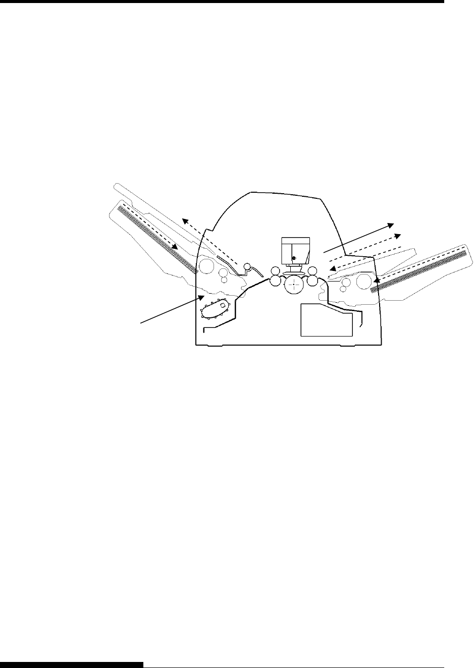
PAPER HANDLING
3-8 User's Manual
With rear tractor and front and rear optional cut sheet feeder and
large stacker and large paper table.
In addition, the front and rear tractor (either is optional) can be mounted.
(2) Rear tractor → Print → Front eject
(3) Paper table → Print → Paper table
(4) Paper table → Print → Rear stacker
(5) Front cut sheet feeder → Print → Paper table
(6) Front cut sheet feeder → Print → Rear stacker
(7) Rear cut sheet feeder → Print → Paper table
(8) Rear cut sheet feeder → Print → Rear stacker
NOTES
When ejecting cut sheets to the paper table, the REMOVE PAPER
indicator blinks after ejecting a cut sheet and stops printing. Before
restarting printing, be sure to remove the cut sheet.
You must remove cut sheets one by one immediately after ejection.
This is required because the printer may load an ejected sheet again
or an ejected sheet may push the previous sheets out of the printer.
To eject sheets larger than A4 size onto the paper table, the paper
table must be replaced with the optional large cut sheet table to
prevent ejected sheets from falling off the paper table.
When printing thin paper, multipart copy paper, or large size paper,
frequently remove the paper from the rear stacker or the paper table.
(2)
[2] [3][5][7]
(3)(4)
[4]
[7][8] [8]
(5)(6)
[6]
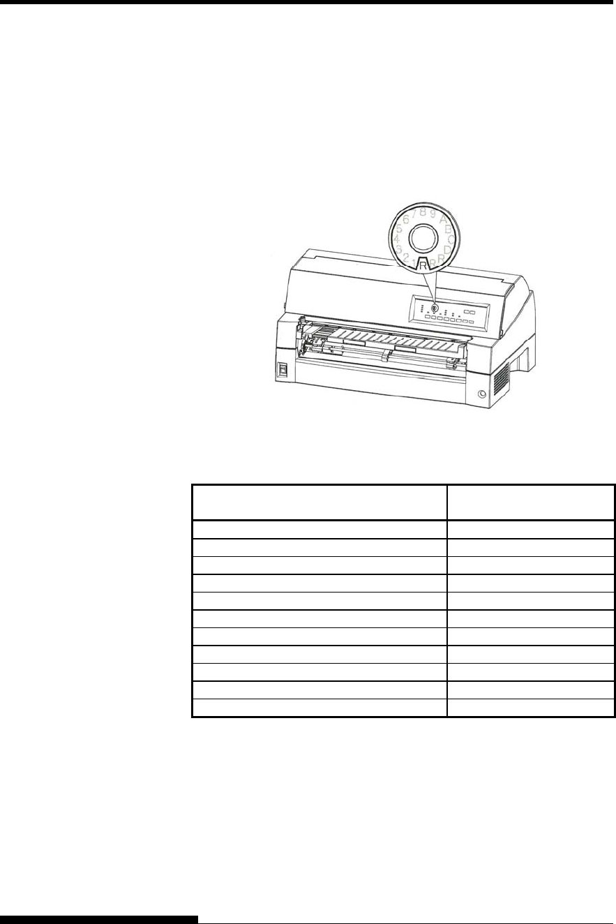
PAPER HANDLING
User's Manual 3-9
The printer can handle paper of different thicknesses, including multipart
forms with up to nine parts (original plus eight copies). For details on
paper thickness specifications, see Appendix B.
The printer automatically adjusts for different paper thicknesses.
You can use the MANUAL GAP DIAL to adjust the paper thickness
manually at manual mode. To place printer manual mode, press AUTO
GAP buttons 2 seconds or more so that AUTO GAP lamp is off.
Adjusting the manual gap dial
Table 3.2 Manual Gap Dial Settings (LED)
Number of Copies
(Including the Original) *1 Setting *2
1 copy 1
2 copies 2
3 copies 3
4 copies 4
5 copies 5
6 copies 6
7 copies 7
8 copies 8
9 copies, Envelopes A
Slips B, C, D
Ribbon replacement R
*1 For carbon-interleaved paper, the carbon counts as one copy.
*2 Vary the setting up or down (including A to R) to optimize printing
especially for labels and envelopes. Select R when replacing a
ribbon or clearing a paper jam.
NOTE
If printing is messy, the ribbon misfeeds, or the paper jams, move
the lever one setting higher.
ADJUSTING FOR
PAPER THICKNESS
(LED)
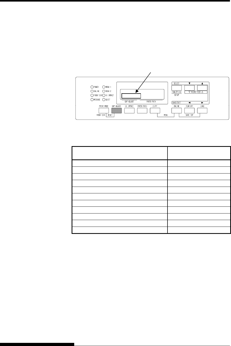
PAPER HANDLING
3-10 User's Manual
The printer can handle paper of different thicknesses, including multipart
forms with up to nine parts (original plus eight copies). For details on
paper thickness specifications, see Appendix B.
The printer automatically adjusts for different paper thicknesses.
You can use the GAP ADJUST button to adjust the paper thickness
manually.
Adjusting the manual gap
Table 3.3 Manual Gap Settings (LCD)
Number of Copies
(Including the Original) *1 Setting *2
1 copy GAP-1
2 copies GAP-2
3 copies GAP-3
4 copies GAP-4
5 copies GAP-5
6 copies GAP-6
7 copies GAP-7
8 copies GAP-8
9 copies, Envelopes GAP-9
Slips GAP-A,B,C
Ribbon replacement GAP-D
*1 For carbon-interleaved paper, the carbon counts as one copy.
*2 Vary the setting up or down (including A to D) to optimize printing
especially for labels and envelopes. Select D when replacing a
ribbon or clearing a paper jam.
NOTE
If printing is messy, the ribbon misfeeds, or the paper jams, move
the lever one setting higher.
ADJUSTING FOR
PAPER THICKNESS
(LCD)
Area for Gap adjust value
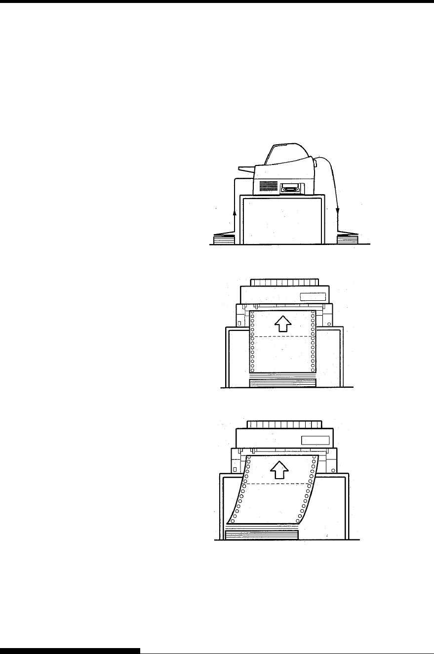
PAPER HANDLING
User's Manual 3-11
Continuous forms paper, fanfolded at the horizontal perforations, is ideal
for printing rough drafts and long files. The paper is fed into the printer
using the forms tractors.
Positioning the Paper Stack
Place the stack of continuous forms paper directly below the rear of the
printer or below the front of the printer. After the paper is installed in the
printer, the paper path should look like this:
Good placement
Bad placement
Placement of continuous forms
USING
CONTINUOUS
FORMS
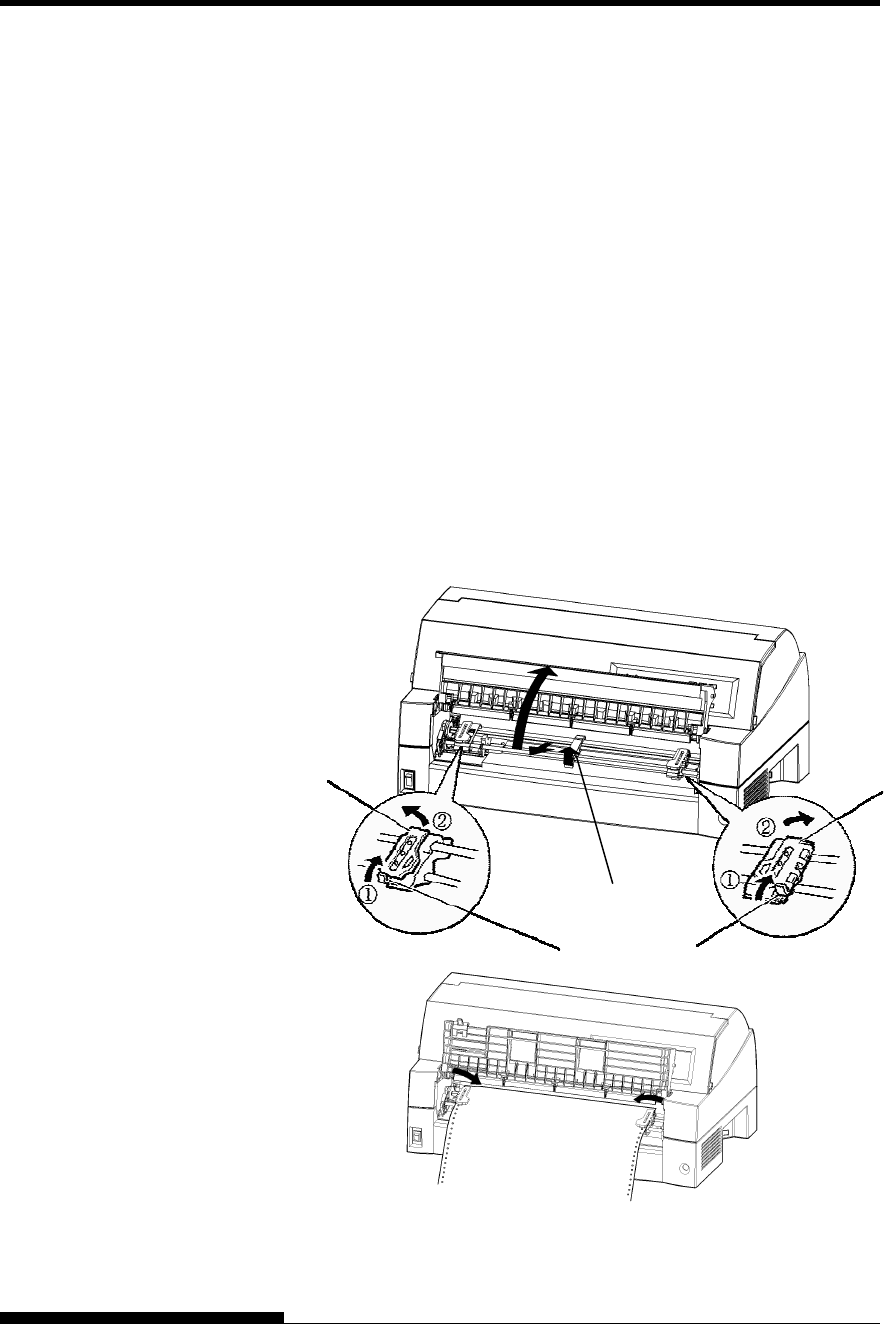
PAPER HANDLING
3-12 User's Manual
Loading Continuous Forms (Front Feed)
This section explains how to use continuous forms as the tractor unit is
installed at the front of the printer. The tractor unit pushes continuous
forms. This condition applies when you first purchase the printer.
Up to 8-ply media can be fed by the front tractor unit.
You can use continuous forms paper even if you have a cut sheet feeder
installed at the rear of the printer.
To load continuous forms paper:
1. Make sure that the printer is turned on. Remove any single-sheet
paper from the printer.
2. Lift up the soundproof cover as shown below.
3. Release the tractor locking levers by pulling them up(①). Open
the tractor paper holders. See the following figure(②).
4. Position the tractors and center guide.
5. Fit the paper feed holes onto the left and right tractor pins.
Adjust the right tractor to the width of the form. Close the paper
holders.
Set the continuous forms to front tractors
Paper Holders Paper Holders
Locking Levers
Center Guide
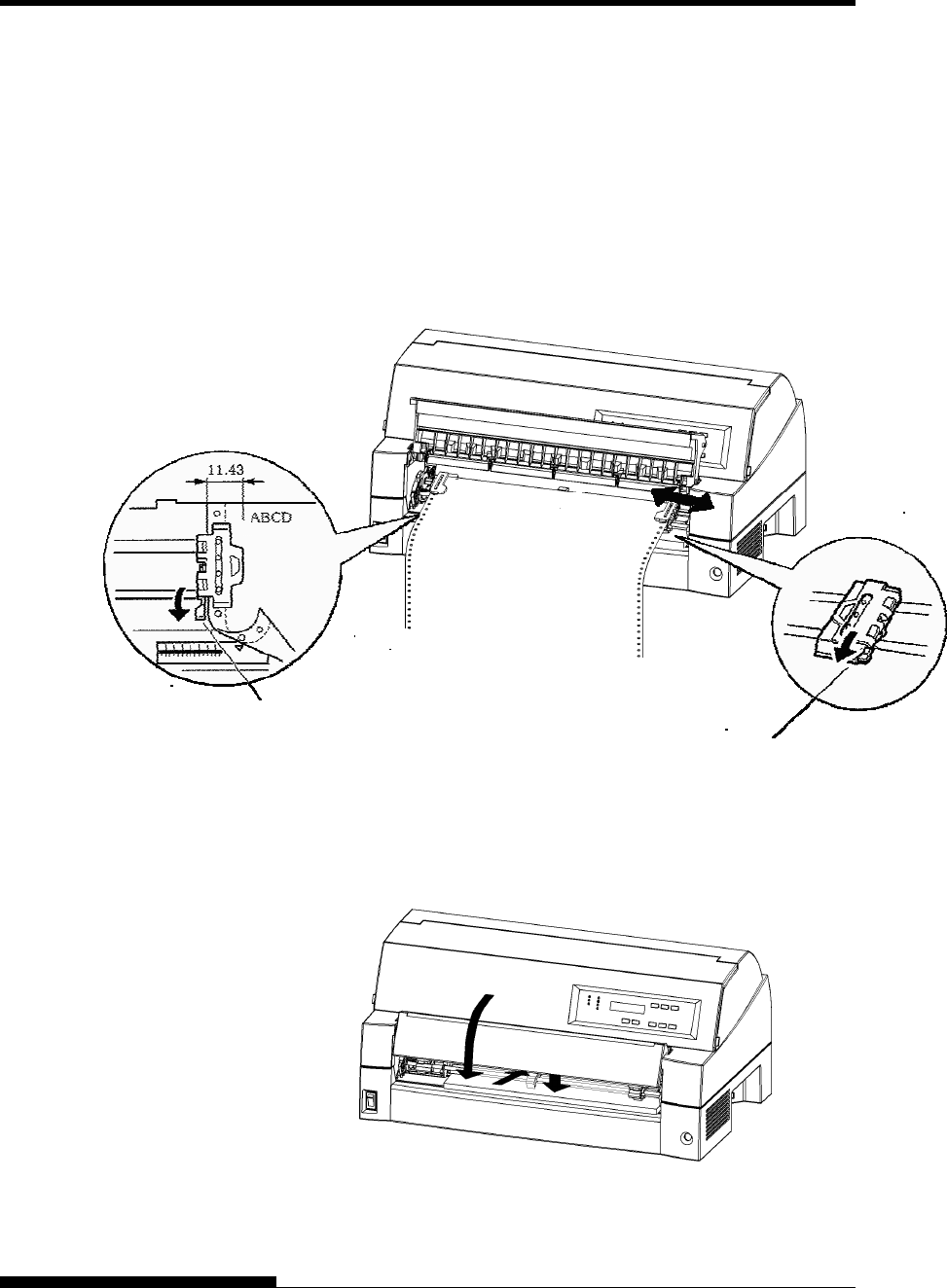
PAPER HANDLING
User's Manual 3-13
6. Adjust the left margin.
Below the left tractor, there is a tractor guide, short inch-based
ruler graduated in 10 columns per inch. Use the ruler to help
position the tractor. When the paper edge is positioned to the
zero line, the left margin is 12 mm (0.5 inch) including
perforation area and the arrow indicates the location of the first
character.
7. Pull the right tractor to stretch the paper taut. Push the right
locking lever down to secure the tractor in place.
Adjusting tractor position
8. Lower the soundproof cover paper table to the down position
(normal mode).
Lowering the cut sheet stand
Locking Lever
Locking Lever

PAPER HANDLING
3-14 User's Manual
CAUTION
• Before lowering the paper table, make sure that the paper holders
are closed.
If the holders are opened, they may cause damage to the tractors
and the paper table.
• Make sure that the paper table is positioned to its normal mode. If
it is not done, jamming may occur when continuous forms paper is
fed.
9. Press the PAPER PATH button to select “FRONT TRACTOR”.
(The indicator lights.)
10. Press the LOAD button to advance the paper to the top-of-form
position. Top-of-form is the first line on which printing can start.
After loading paper, the printer goes into online mode.
11. Print a sample page and check the page margins. Make the
following adjustments, as necessary:
• Horizontal alignment. Move the forms tractors as required.
• Top-of-form setting (see Chapter 5).
• Margin settings. Use your software or the printer setup
mode (see Chapter 5).
NOTE
Do not open the front cover during printing.
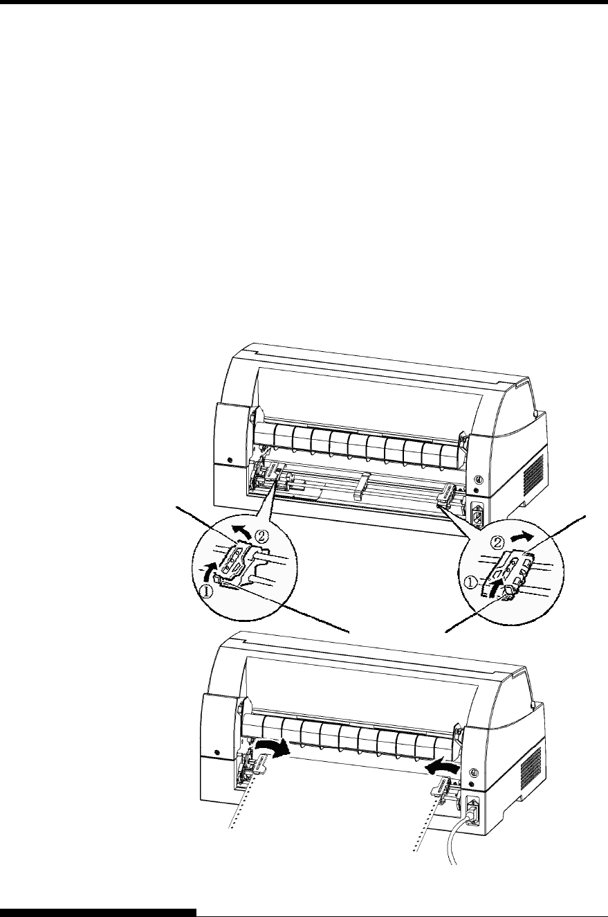
PAPER HANDLING
User's Manual 3-15
Loading Continuous Forms (Rear Feed)
A tractor is supplied as standard and is attached to the front of the printer.
It can be attached to the rear of the printer. You can also buy a tractor
unit as an additional rear tractor unit.
A maximum of 8-ply media can be fed from the rear tractor unit.
For reinstalling the tractor unit for rear feed, see page 2-10 to 2-13.
1. Release the tractor locking levers by pulling them up(①). Open
the tractor paper holders. See the following figure(②).
2. Position the tractors and center guide.
3. Fit the paper feed holes onto the left and right tractor pins.
Adjust the right tractor to the width of the form. Close the paper
holders.
Locking Levers
Paper Holder Paper Holder
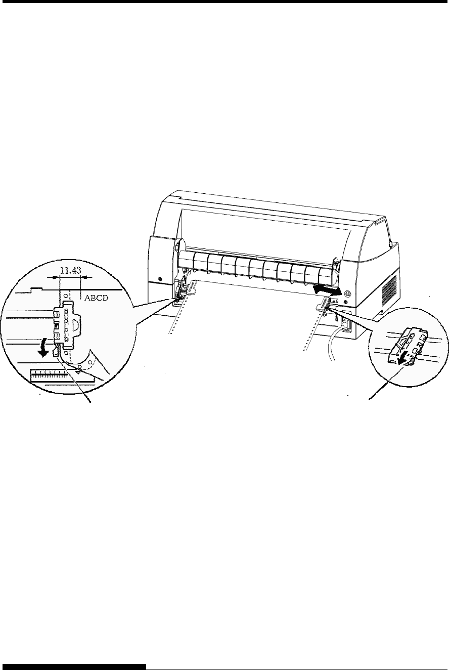
PAPER HANDLING
3-16 User's Manual
4. Adjust the left margin.
Below the left tractor, there is a tractor guide, short inch-based
ruler graduated in 10 columns per inch. Use the ruler to help
position the tractor. When the paper edge is positioned to the
zero line, the left margin is 12 mm (0.5 inch) including
perforation area and the arrow indicates the location of the first
character.
5. Pull the right tractor to stretch the paper taut. Push the right
locking lever down to secure the tractor in place.
6. Press the PAPER PATH button to select REAR TRACTOR (the
indicator lights).
7. Press the LOAD button to advance the paper to the top-of-form
position. Top-of-form is the first line on which printing can start.
After loading paper, the printer goes into online mode.
8. Print a sample page and check the page margins. Make the
following adjustments, as necessary:
• Horizontal alignment. Move the forms tractors as required.
• Top-of-form setting (see Chapter 5).
• Margin settings. Use your software or the printer setup
mode (see Chapter 5).
Lock Lever Lock Lever

PAPER HANDLING
User's Manual 3-17
Unloading Continuous Forms
To unload continuous forms:
1. Make sure that the FRONT TRACTOR or REAR TRACTOR
indicator lights.
2. Press the LOAD button. The continuous forms paper is retracted
to the park position. If the paper cannot be retracted in one
operation, continue to press the LOAD button until the paper is
parked.
NOTE
The printer can retract continuous forms paper up to a
maximum of 55.8 cm (22 inches) per operation.
3. To remove the paper, raise the tractor paper holders and lift out
the paper.
NOTE
If continuous forms are unloaded without stopping, the
paper may slip off the tractors.
Tearing Off Continuous Forms
Your printer has a special “tear-off edge” that allows you to tear off
printed pages without wasting paper. The tear-off edge is located on the
front and rear of the printer.
To tear off continuous forms using the tear-off edge:
1. Press the TEAR OFF button. The bottom perforation of the last
page advances to the tear-off edge. If you specified TEAR OFF:
AUTO using the HARDWARE function in setup mode, the
paper automatically advances to the tear-off edge at the end of
each job (or when the printer has printed all the data received).
NOTE
If the bottom perforation of your paper is not positioned at
the tear-off edge, the length of your paper may not be
specified correctly in your software or the printer setup
mode.
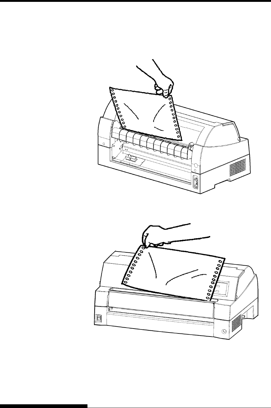
PAPER HANDLING
3-18 User's Manual
Check that the paper length is specified correctly. For
information on specifying page length using setup mode, see
Chapter 5.
2. Tear the paper off at the perforation.
Tearing off continuous forms (front feed)
Tearing off continuous forms (rear feed)
3. Press any button to retract the forms back to the top-of-form
position.
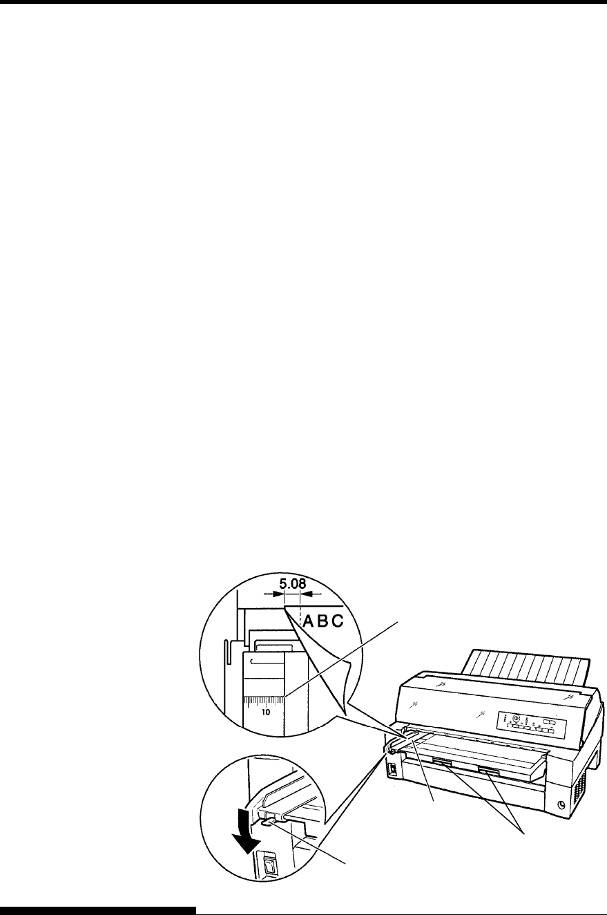
PAPER HANDLING
User's Manual 3-19
This section describes how to load paper from the paper table or cut sheet
feeder. The paper table allows paper to be loaded manually, one sheet at
a time. A cut sheet feeder allows paper to be loaded automatically from
the paper bin.
Loading a Paper From The Paper Table.
(option)
To load a sheet of paper from the paper table:
1. Make sure that the printer is turned on.
2. Press the PAPER PATH button to select CUT SHEET (the
indicator lights).
3. Press the FRONT DIR button to select the direction of ejecting
single sheets.
• Front ejection — FRONTDIR indicator lights.
• Rear ejection — FRONTDIR indicator doesn’t light.
4. Adjust the left margin.
On the left hand side of the paper table, a scale graduated in
units of 1 [mm]. When the paper guide is positioned at scale 0
[mm], the left margin is 5 mm (0.2 inch).
Push the lock lever down to secure the guide.
5. Pull the sub guide out as required to accommodate the paper
size.
NOTE
When using the paper whose width is under 100 mm (4 inch),
position the paper guide at scale 0 [mm].
USING SINGLE
SHEETS
0(zero)
Movable guide
Lock lever
Sub guide
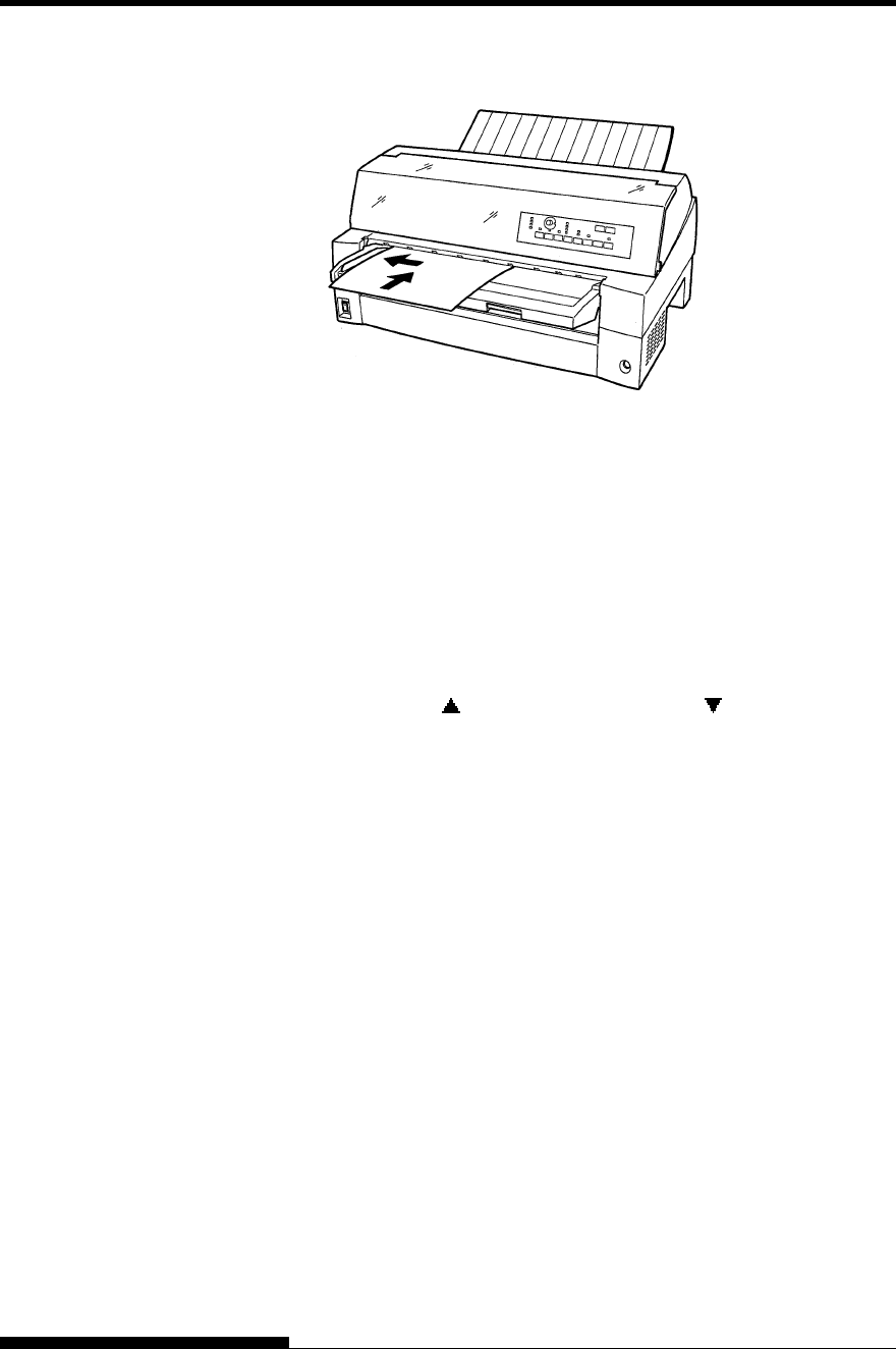
PAPER HANDLING
3-20 User's Manual
Preparing to load a sheet of paper
Loading a sheet of paper
6. Insert a sheet of paper into the paper table. Make sure that the
front edge of the paper engages snugly with the feed roller.
NOTE
If paper skews when it is loaded, the printer does not print and ejects
the paper. (This function can be disabled by a setting in setup mode.)
7. Press the LOAD button. The paper will advance to the top-of-
form position. The top-of-form position is the first line on which
printing can start. To adjust the position of the paper slightly,
press the MICRO FEED button or the MICRO FEED
button. The paper will move forward or backward in 1/180-inch
increments.
After loading paper, the printer goes into online mode.
8. Print a sample page and check the page margins. Make the
following adjustments, as necessary:
• Horizontal alignment. Readjust the paper guide if required.
• Top-of-form setting (see Chapter 5).
• Margin settings. Use your software or the printer setup
mode (see Chapter 5).
NOTE
Do not open the front cover during printing. With the cover open
detection option installed, the printer never prints while the front
cover is open. Close the front cover to perform printing.
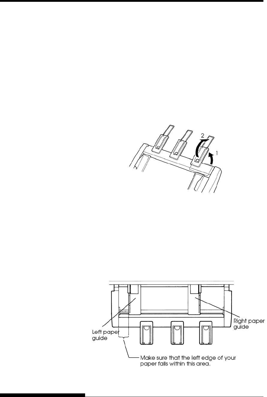
PAPER HANDLING
User's Manual 3-21
Loading Paper from the Cut Sheet Feeder
(Option)
A cut sheet feeder (SF940) allows automatic printing on single sheets
without the need to manually insert the sheets one-by-one. This can save
you a lot of time when printing long files using single sheets. See
Chapter 8 for more information on the cut sheet feeder.
For installation of the feeder, refer to its user’s manual. When a feeder is
mounted and the feeder cable is connected, the printer automatically
knows the feeder type and controls the feeder accordingly.
1. Two steps of extension are available for supporting long sheets
of paper.
Steps of extension
2. Adjust the left margin.
To help align the left paper guide, use the inch-based ruler
located behind the paper guides. The ruler is graduated in 10
columns per inch. For example, setting the left paper guide 12.7
mm (0.5 inch) from the left gives a left margin of 6.3 mm (0.25
inch) plus the left margin specified by your software or the
printer setup mode.
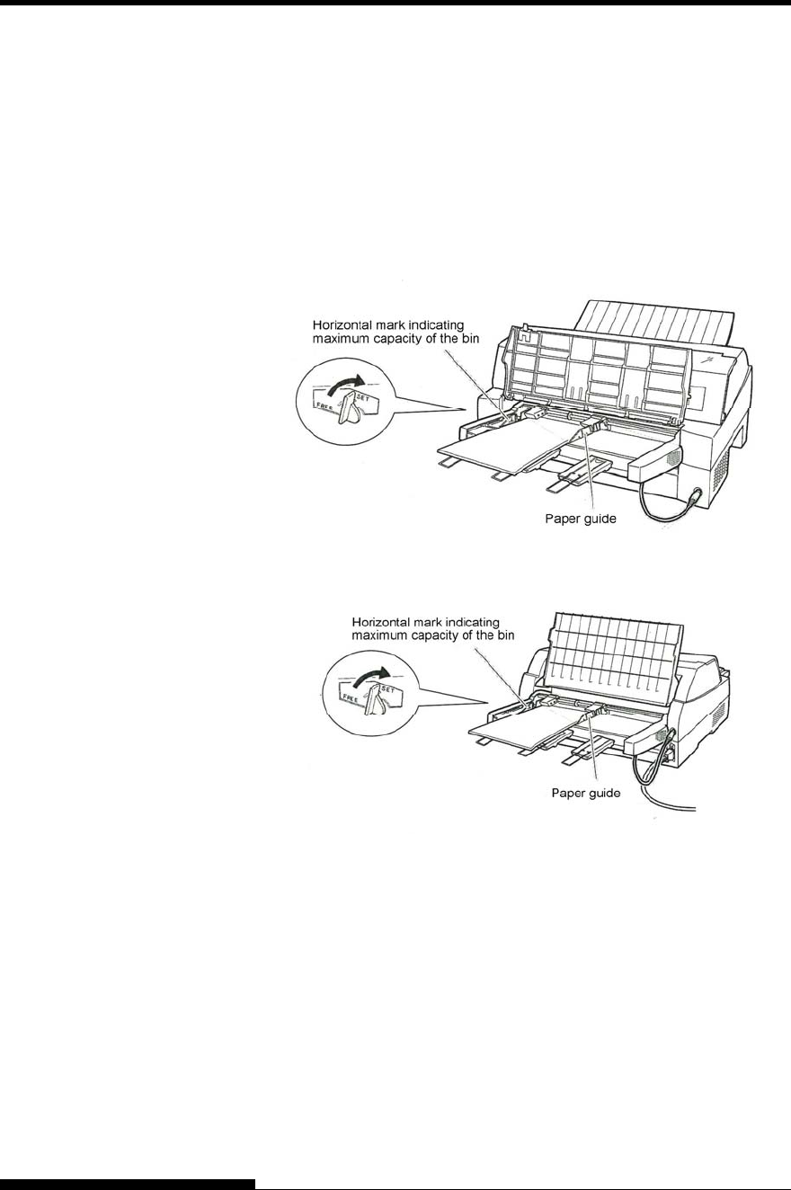
PAPER HANDLING
3-22 User's Manual
• Slide the right paper guide until the distance between the
two guides is the approximate width of your paper.
3. Manually fan the stack of paper and place it in the paper bin.
NOTE
A short horizontal mark inside the left paper guide indicates
the maximum capacity of the bin. Make sure that your
paper stack does not exceed this horizontal mark.
Loading the cut sheet feeder (Front feed)
Loading the cut sheet feeder (Rear feed)
4. Readjust the right paper guide, leaving a slight gap between the
paper guide and the right edge of the paper. Slide the guide to
the approximate width of the paper, or the paper will not be
loaded properly. Pull the right locking lever forward.
5. Push the bin lever down to the “SET” position.
6. Load paper to the top-of-form position using either of the
following methods:

PAPER HANDLING
User's Manual 3-23
• Load the paper manually. Press the LOAD button. The
paper will advance to the top-of-form position. Adjust the
position of the paper as needed by the MICRO button or
the MICRO button (micro feed).
• Load the paper using your software. Press the ONLINE
button to place the printer online. Load paper according to
the instructions in your software documentation. Most
software packages load paper automatically.
After loading paper, the printer goes into online mode.
7. Print a sample page and check the page margins. Make the
following adjustments, as necessary:
• Horizontal alignment. Readjust the paper guides if required.
• Top-of-form setting (see Chapter 5).
• Margin settings. Use your software or the printer setup
mode (see Chapter 5).
NOTE
Do not open the front cover during printing.
Ejecting Single Sheets
If you print using software, each sheet is ejected automatically when the
end of the printed page is reached. To manually eject sheets of paper, use
the following method:
• Press and hold down the LF/FF button to execute a forward
form feed.

PAPER HANDLING
3-24 User's Manual
The following functions are available whether the printer is online or
offline.
Line Feed/Form Feed
Use the line feed/form feed function to move paper forward.
• Pressing and holding down the LF/FF button feeds one sheet of
paper.
• Pressing the LF/FF button once advances the paper one line (do
not hold the button more than three seconds).
Micro Feed
Use the micro feed function to fine tune the position of the paper.
• Press the MICRO button to feed paper backward by 1/180
inch.
• Press the MICRO button to feed paper forward by 1/180 inch.
Remember that the top-of-form will differ from the original setting.
Load Position Adjust
Use also the micro feed function to adjust the load position of the paper.
• When the MICRO button or the MICRO button is used
immediately after the LOAD button is pressed, the adjusted
position of paper is retained as the new load position until the
power is turned off.
• Pressing the ONLINE and LOAD buttons simultaneously saves
the new position permanently.
The load position can be set for single sheets and continuous forms
respectively.
FEEDING AND
POSITIONING
PAPER
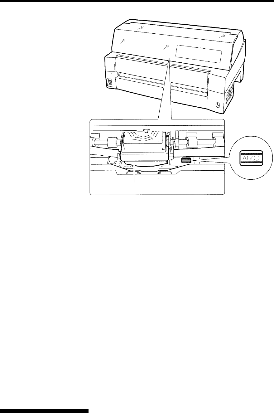
PAPER HANDLING
User's Manual 3-25
Adjusting Load Position by Using Window of Card Guide
The lines of window on the right side of card guide indicate printing line.
So use this as a guide to adjust load position.
Print Head

PAPER HANDLING
3-26 User's Manual
General Tips
• Use high-quality paper. Do not use paper that is wrinkled or
curled at the edges.
• Do not use paper with staples or metal parts.
• Do not use paper with unpredictable variations in thickness,
such as paper with partial multilayers, paper with embossed
printing, and labels with the backing sheet exposed.
• Store paper in a clean, dry environment.
Multipart Forms
• Avoid using carbon-interleaved single sheets if possible.
Printing tends to become misaligned on the bottom sheet.
• To ensure smoother feeding of paper-stapled, multipart forms,
raise the rear stacker to support the forms.
Envelopes
When printing envelopes, use the paper table or the manual feed slot of
the cut sheet feeder. Note the following:
• When loading envelopes, make sure that the envelope flaps face
forward. Otherwise, the envelopes may jam in the printer.
Labels
• Be careful to check operating conditions when using labels.
Labels are sensitive to temperature and humidity.
• Only use labels mounted on continuous forms backing sheets.
Do not print labels mounted on single sheet backing. Labels
mounted on single sheet backing tend to slip and printing
becomes crooked.
• Do not feed labels backwards using the LOAD button from the
control panel. Jamming may occur.
• Do not use the printer tear-off feature when printing labels. If
the labels are retracted, the backing may peel off and the labels
may jam in the printer.
• Test-print labels before running a job. If jams occur, go into
setup mode and
- set the paper thickness control to manual mode and
- set the paper thickness indicator to a wider position
manually.
If jamming problems continue, try a different type of label.
TIPS ON PAPER
HANDLING
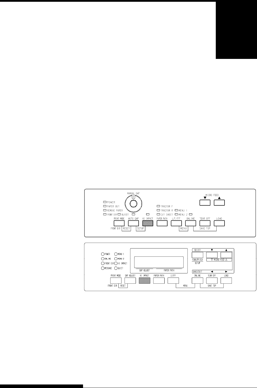
User's Manual 4-1
4
CHAPTER 4 PRINTING
PRINTING
This chapter describes the following everyday
printing operations:
• Using multipart form (hi impact mode)
• Selecting the print mode(quiet mode)
• Starting, stopping, or resuming printing
• Removing printed pages
• Clearing the print buffer
• Selecting the print features
Instructions for loading paper are given in Chapter 3.
This printer has enough capability to print multipart forms. When
superior copy capability is required, use the hi impact mode. Press the
HI IMPACT button on the printer control panel. This function is valid
when the HI IMPACT indicator lights.
Print control panel
NOTE
• Setting hi impact mode by pressing the HI IMPACT button is
cancelled when you turn off the printer.
• If you wish to have the hi impact mode set on power-on, save the
setting in setup mode.
MULTIPART FORMS
(HI IMPACT MODE)
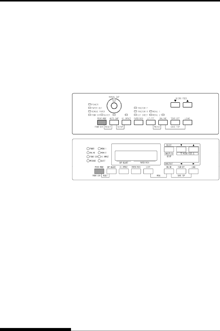
PRINTING
4-2 User's Manual
Quiet mode reduces acoustic noise as follows.
The consecutive dots are omitted (LQ).
The print speed is slowed to LQ speed (except for LQ).
Skipping the space (no characters) at higher speed doesn’t work.
To select Quiet mode:
1. Press the ONLINE button to place the printer online.
2. Press the PRINT MODE button. When QUIET indicator lights,
QUIET MODE is valid.
Print control panel
NOTE
• Setting quiet mode by pressing the PRINT MODE button is
cancelled when you turn off the printer.
• If you wish to have the quiet mode set on power-on, save the
setting in setup mode.
PRINT MODE
(QUIET MODE)

PRINTING
User's Manual 4-3
Starting Printing
Before you start to print, make sure that paper is loaded.
To start printing, press the ONLINE button to place the printer online.
Then start your software.
Stopping Printing
To stop printing immediately, press the ONLINE button to place the
printer offline. You can also use your software to stop printing, but there
will be a slight delay before printing stops. Any data sent to the print
buffer but not yet printed is stored until you resume printing. Data in the
print buffer is lost if you turn the printer off.
To resume printing, press the ONLINE button again. To cancel printing,
use the cancel commands provided by your software or computer. To
clear the print buffer, place the printer offline and press the PRINT
MODE and AUTO GAP buttons. Any data sent to the print buffer before
you canceled printing will be lost.
Resuming from a Paper-Out
The printer can “sense” when paper runs out. Depending upon how PPR-
OUT (paper-out) is set in setup mode, the printer either:
• Stops printing and lights the red PAPER OUT indicator, or
• Continues printing until no more data remains in the printer.
See Chapter 5 for details on setting PPR-OUT. The factory default is to
stop printing if continuous forms paper runs out and to continue printing
if single sheet paper runs out.
To resume printing when paper runs out, use either of the methods
described below:
Printing the remaining lines on a page
This method is convenient to continue printing under the paper-out
condition, but is not available when the cut sheet feeder is used.
1. Press the ONLINE button. The printer returns to online mode,
prints or feeds one line, and the PAPER OUT indicator lights up
again.
2. Repeat this procedure until the full page is printed. Line spacing,
however, may be uneven.
STARTING OR
STOPPING
PRINTING

PRINTING
4-4 User's Manual
CAUTION
When printing remaining lines, be careful not to print on the platen.
Printing on the platen may damage both the platen and the print head.
Continuing printing after supplying paper
1. Install paper on the forms tractors or on the cut sheet stand, or in
the cut sheet feeder bin, as described in Chapter 3.
2. To load the first sheet of paper, press the LOAD button. The
PAPER OUT indicator will turn off.
3. Press the ONLINE button to place the printer online. The printer
resumes printing.
NOTE
For continuous forms paper, the page where printing
stopped and the page where printing resumes may be
incorrectly printed. In this case, wait for the entire job to
finish printing. Then reprint the incorrect pages.
Resuming after an Area Over warning
The printer senses the left and right edges of paper and stores their
positions when the paper is loaded. If your software will print data past
either edge, the printer ignores that data but does not stop printing.
The AREA OVER detection control functions when AREACNT (area
control) is set to ENABLE in setup mode. See Chapter 5 for information
on setting AREACNT. The factory default is not to sense the edges. If
paper is dark-colored or preprinted, the printer may not be able to sense
the edges correctly. In this case, disable the sensor.

PRINTING
User's Manual 4-5
This section describes the best methods for removing single sheets or
continuous forms paper after printing.
Removing Single Sheets
When you print using software, the printer automatically ejects each
sheet of paper when the end of the printed page is reached. To eject
sheets manually, use one of the following methods:
• Press and hold down the LF/FF button to execute a form feed.
Removing Continuous Forms
To avoid wasting paper, use the printer tear-off function to remove
continuous forms paper. Press the TEAR OFF button to advance the
perforation to the tear-off edge. Tear the paper off, and then press any
button to retract the paper back to the top-of-form position. See Chapter
3 for more detailed instructions.
Place the printer offline. Press the PRINT MODE and AUTO GAP
buttons simultaneously to clear all data from the print buffer. This
method is useful when you cancel a print operation and do not want to
continue printing data already sent to the printer.
This method does not change or clear MENU1 and MENU2 settings,
paper loading position settings, and downloaded fonts.
REMOVING
PRINTED PAGES
CLEARING THE
PRINT BUFFER

PRINTING
4-6 User's Manual
The print features you select determine how your printed pages will look.
Print features include the following:
• Print quality
• Fonts
• Pitch (characters per horizontal inch)
• Page length and width
• Line spacing (lines per vertical inch)
To select print features, you can use either commercial software or the
printer control panel. The method you use depends on the capabilities of
your software. If your software has most of the features you require, you
may rarely – if ever – have to use the control panel. In fact, your software
often overrides the printer settings.
If your software has limited options, you can use the printer control panel
to select print features. Sometimes, the control panel enables you to
select features not available through your software. For example, you can
select downloaded fonts not supported by your software.
Using Commercial Software
Many commercial software packages offer a wide variety of print
features, including some features that are not supported by this printer.
For example, software often provides a wider range of font sizes than the
printer can accommodate. Software also allows you to specify multiple
fonts on a page.
To determine which features your software supports and how to select
them, refer to your software documentation.
SELECTING PRINT
FEATURES
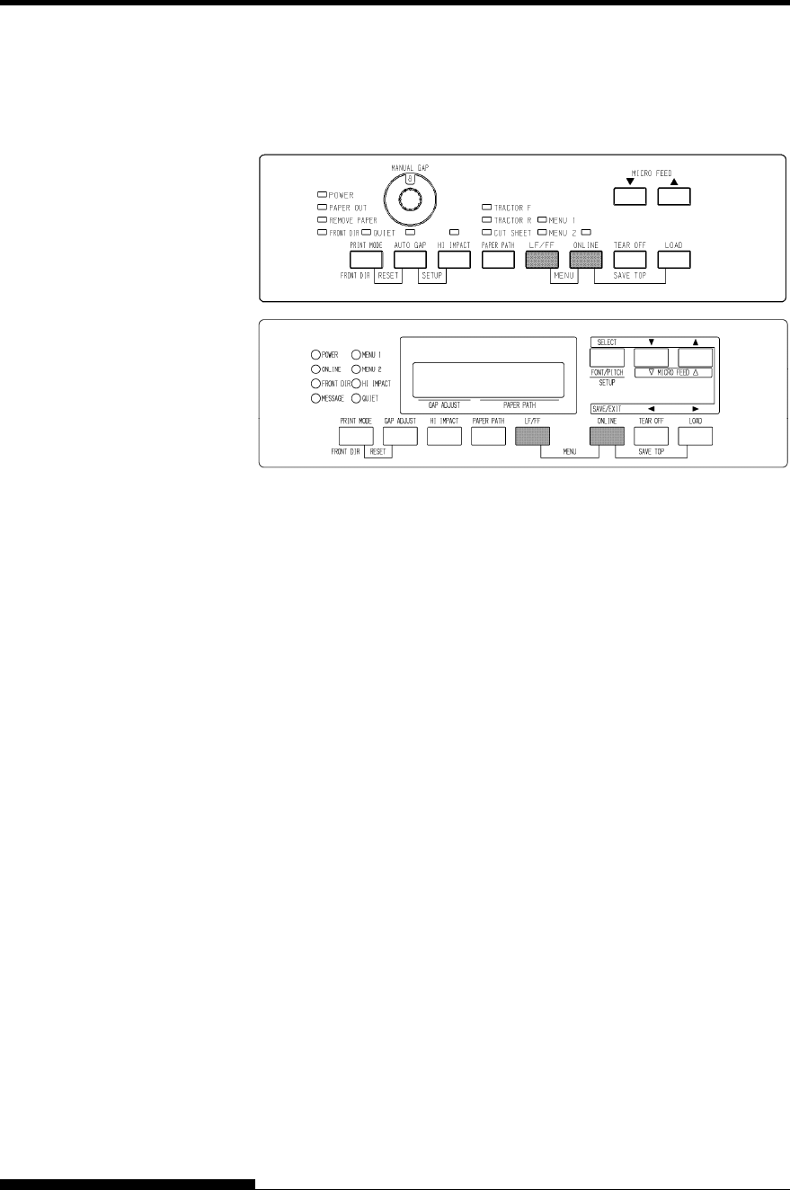
PRINTING
User's Manual 4-7
Using the Control Panel
Use the ONLINE and LF/FF button to directly select one of the two
menus.
Printer control panel
The ONLINE and LF/FF buttons specify MENU1 or MENU2, either of
which allows you to specify different sets of options in advance. Some of
the print features include emulation, print quality, character pitch, and
line spacing. To setup the print features to MENU1 and MENU2, refer to
the chapter 5.
When you first turn the printer on, the MENU 1 indicator is lit; that is, all
of the print features assigned to MENU1 are enabled. However, you can
easily switch to MENU2 before printing.
NOTE
For easy reference, keep a list of your current MENU 1 and MENU 2
settings near the printer. To print a list of current settings, see the
section Printing a List of Selected Options in Chapter 5. You may
also want to use the space provided in Table 4.1 to record your
settings.
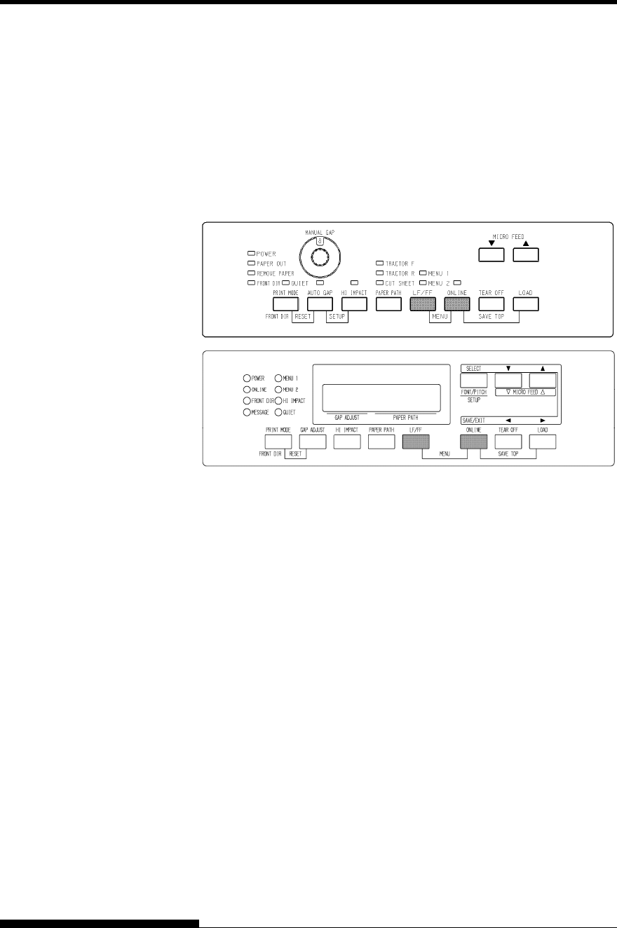
PRINTING
4-8 User's Manual
Selecting MENU1 or MENU2
When you first turn the printer on, MENU1 is selected. To change to
MENU2 or back to MENU1, proceed as follows:
1. Press the ONLINE button to place the printer offline.
2. Repeatedly press the ONLINE and LF/FF buttons. The lighted
indicator (1 or 2) shows the menu selected. When the menu
selection is changed, the font (font, pitch, and quality) assigned
in the selected menu becomes valid.
3. Press the ONLINE button to return online. You are ready to
print using the selected menu.
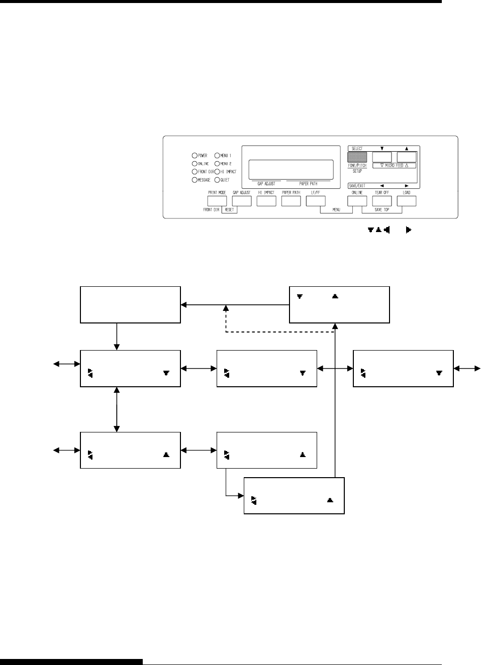
PRINTING
User's Manual 4-9
Using the Control Panel (LCD type only)
LCD type Control panel also can select print features including
FONT/PITCH/QUALITY that assigned current MENU1 or 2 directly.
To select print features enter select mode as follows.
1. Press the ONLINE button to place the printer online.
2. Press the FONT/PITCH button to enter select menu.
3. To move layer and in transverse direction, use , , and
buttons.
4. To save or exit press SAVE/EXIT buttons.
Font/pitch/qual setting mode.
ONLINE
AUTO TRACTOR F
FONT/PITCH/QUAL
FONT
FONT/PITCH/QUAL
PITCH
FONT/PITCH/QUAL
QUALITY
FONT
*COUR 10
FONT
PRSTG12
FONT
*PRSTG12
FONT/PITCH button
SELECT SW
:SAVE :CANCEL
SAVE/EXIT button
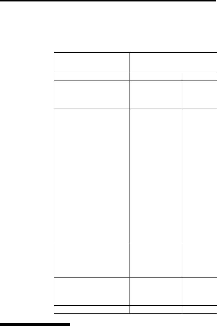
PRINTING
4-10 User's Manual
Table 4.1 MENU1 and MENU2 Settings
Setting Default Settings
For easy reference, check (
9
) or record
your default settings in the space below.
Print Feature MENU1 MENU2
Emulation
Fujitsu DPL24C PLUS
IBM Proprinter XL24E
Epson ESC/P2
Font
Courier 10
Prestige Elite 12
Compressed 17
Boldface PS
Pica 10
Correspondence
OCR-B 10
OCR-A 10
Courier Normal 10 (outline)
Courier Bold 10 (outline)
Courier Italic 10 (outline)
Nimbus Sans Normal PS (outline)
Nimbus Sans Bold PS (outline)
Nimbus Sans Italic PS (outline)
Timeless Normal PS (outline)
Timeless Bold PS (outline)
Timeless Italic PS (outline)
Downloaded font 0
Downloaded font 1
Print quality
Letter
Report
Draft
High-speed draft
Pitch
2.5, 3, 5, 6, 10, 12
15, 17, 18 or 20 cpi
Proportional spacing
Other features:

User's Manual 5-1
5
CHAPTER 5 USING SETUP MODE
USING SETUP MODE
Your printer has two modes: normal and setup.
Normal mode is used for everyday printer operations
and is explained in Chapters 3 and 4.
Setup mode serves two purposes. It enables you to:
• Select the printer’s optional settings
• Help diagnose printer problems
These setup mode functions can be done either offline, using the printer
control panel (offline setup), or remotely, using a setup program in your
computer system or software (online setup). Primarily, this chapter
explains how to use the offline setup mode. The online setup mode,
which is reviewed briefly at the end of this chapter, is valid in all
emulations.
Optional settings on the printer include the emulation, fonts, pitch, page
length and page width, serial interface options, and the top-of form
setting. When you save your settings in the printer’s permanent memory,
they become the new settings or defaults. These defaults are invoked
whenever you turn on the printer. For example, if you save DPL24C
PLUS as the default emulation, DPL24C PLUS is invoked when you turn
on the printer.
The printer diagnostic functions are SELF-TST, HEX-DUMP, and
V-ALMNT. These functions are helpful for printer trouble-shooting, as
described in Chapter 7.
The sections in this chapter are presented in logical sequence. If you are
a first-time user, be sure to read the following sections first:
• Entering Setup Mode
• Overview of Setup Mode
These sections will familiarize you with how setup mode works. Once
you understand the basics, use the following sections to select printer
options that are compatible with your computer system’s hardware and
software setup:
• Printing a List of Selected Options
• Deciding Which Options to Change
• MENU1 and MENU2 Items and Options
• Hardware Items and Options
• Print Position Adjustment Items and Options
• Configuration Items and Options
HOW TO USE THIS
CHAPTER
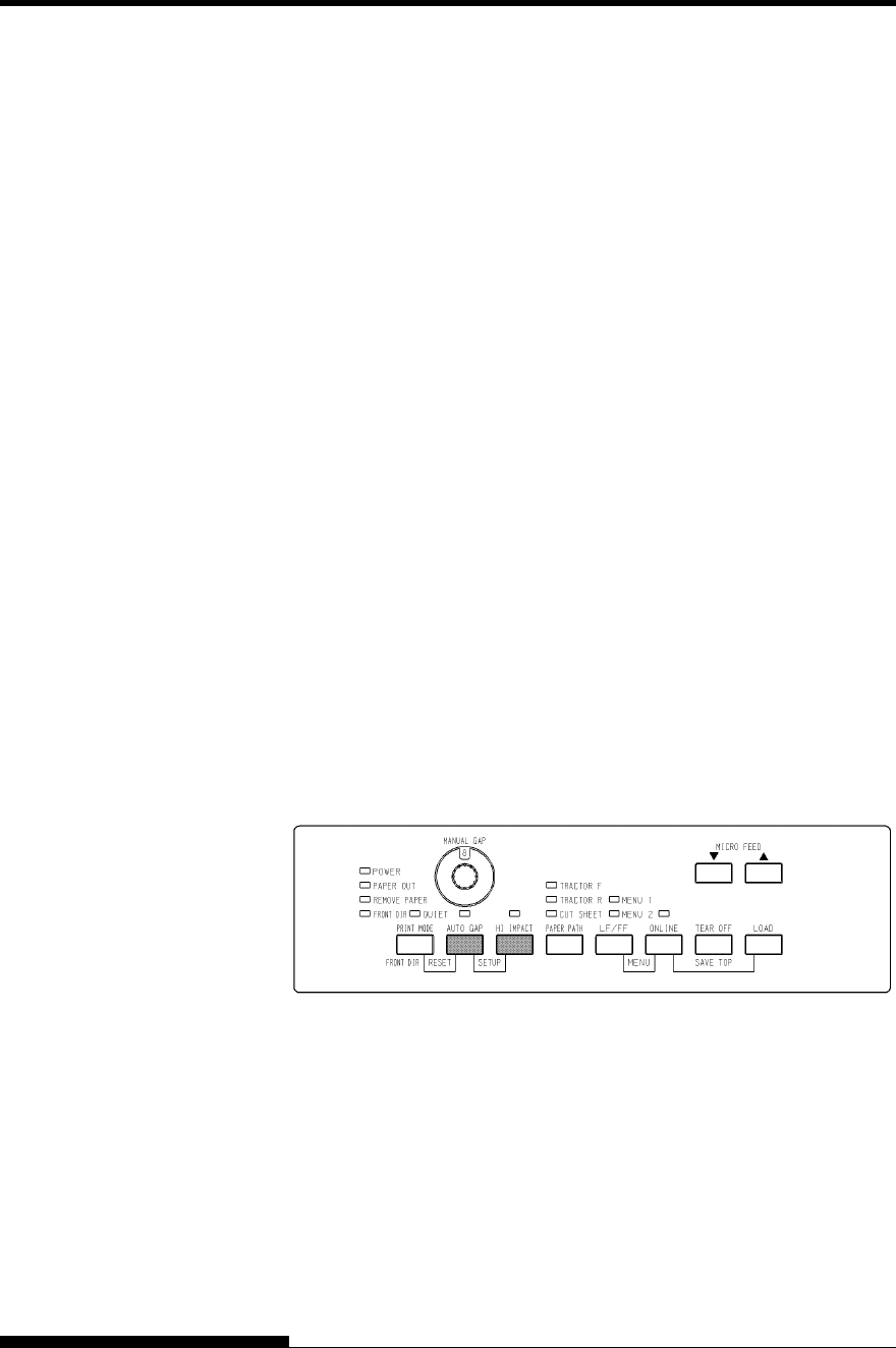
USING SETUP MODE
5-2 User's Manual
• Head Gap Adjustment Items and Options
• Exiting and Saving
To restore the printer default settings (factory defaults or power-on
defaults), see the section Resetting Defaults later in this chapter.
For information on using the SELF-TST, HEX-DUMP, and V-ALMNT
functions, see the section Using the Diagnostic Functions later in this
chapter.
For Experienced Users:
Once you are familiar with setup mode, you may want to use the
flowchart at the end of this chapter for quick reference. The flowchart
lists all printer setup functions, items, and options.
Before entering setup mode, load continuous forms paper from the front
tractor into the printer as described in Chapter 3. Several sheets of paper
may be required to make all of your setup mode selections.
To enter setup mode, follow these steps:
1. Make sure that front continuous forms paper is loaded and press
the PAPER PATH button to select the appropriate paper path.
If continuous forms paper is fed from the rear or a CSF is
mounted, the printer does not enter SETUP mode.
2. Press the ONLINE button to place the printer offline.
3. Press the AUTO GAP and HI IMPACT buttons simultaneously
until the printer beeps.
Entering setup mode
If you do not hear a beep or an alarm beep (beeps four times),
you are not in setup mode. Place the printer offline and try again.
ENTERING SETUP
MODE(LED)
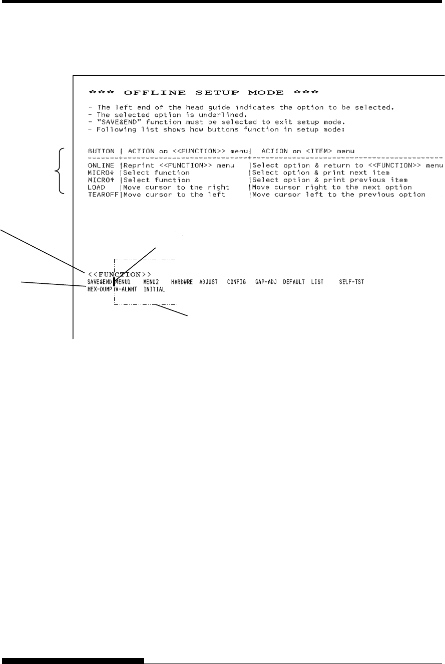
USING SETUP MODE
User's Manual 5-3
4. When the printer enters offline setup mode, it prints the
following information.
Initial printout in setup mode
The initial printout contains a header, help menu, and <<FUNCTION>>
menu. The header tells you that the printer is offline and in setup mode.
The help menu provides a quick summary of how to use setup mode. The
<<FUNCTION>> menu lists all of the functions available to you in setup
mode. Note that the cursor on the left edge of the aluminum print guide is
initially positioned at the SAVE & END function.
Setup mode can also be entered by turning off the printer, then turning
the printer back on while pressing the AUTO GAP and HI IMPACT
buttons simultaneously until the printer beeps.
Function buttons in
Setup mode
<<Function>> menu
Function
Card guide (aluminum print guide (head guide))
Cursor
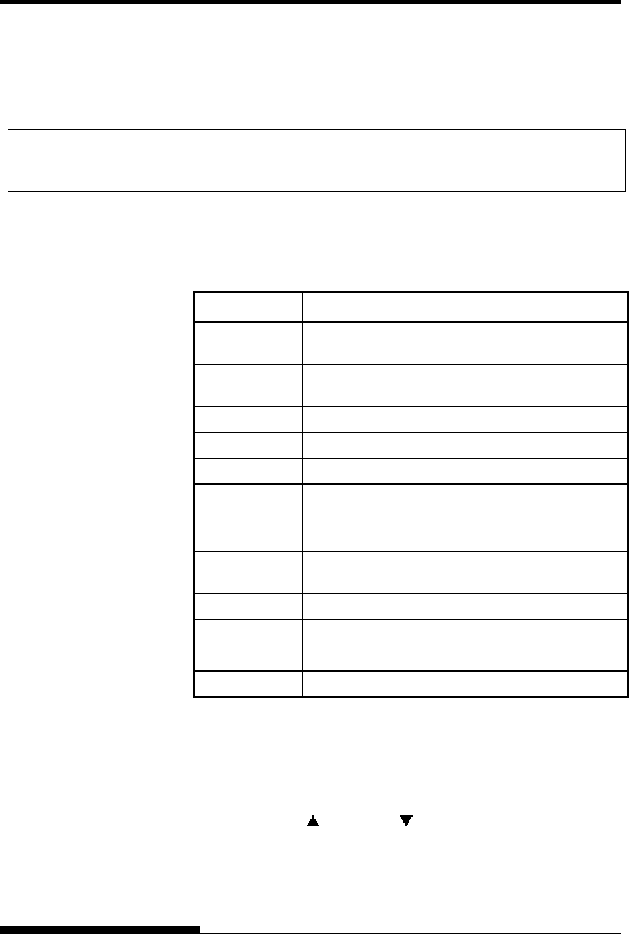
USING SETUP MODE
5-4 User's Manual
When you enter setup mode, the following <<FUNCTION>> menu is
printed:
<< FUNCTION >>
SAVE&END MENU1 MENU2 HARDWRE ADJUST CONFIG GAP-ADJ DEFAULT LIST SELF-TST
HEX-DUMP V-ALMNT INITIAL
Table 5.1 summarizes the purpose of each function.
Table 5.1 Setup Mode Functions
Function Purpose
SAVE & END Exits setup mode and saves any changes made while
in setup mode.
MENU1 and
MENU2
Assigns print features to MENU1 and MENU2 on the
printer control panel.
HARDWRE Changes the printer hardware options.
ADJUST Changes the print position adjustment options.
CONFIG Changes the configuration options.
GAP-ADJ Adjust the gap between the print head and printing
paper.
DEFAULT Resets factory defaults in MENU1 and MENU2.
INITIAL Resets factory defaults in MENU1, MENU2,
HARDWRE, ADJUST, CONFIG, GAP-ADJ.
LIST Prints a list of all currently selected options.
SELF-TST Runs the self-test.
HEX-DUMP Prints hex dumps.
V-ALMNT Checks and corrects vertical print alignment.
To select a function from the <<FUNCTION>> menu:
1. Repeatedly press the “TEAR OFF” or “LOAD” button to
position the cursor on the left edge of the aluminum print guide
at the function you require.
2. Press the button or the button to select the function. If the
function has items and options, the printer prints the first item
and its options. The MENU1, MENU2, HARDWRE, ADJUST,
CONFIG, and GAP-ADJ functions contain items that have
selectable options. The other functions have neither items nor
options.
OVERVIEW OF
SETUP MODE (LED)

USING SETUP MODE
User's Manual 5-5
The first three MENU1 items and their options are shown below.
Items are enclosed in single brackets < >. A short underlined
portion is current option and long underlined portion is selected
option.
< EMULATE>DPL24C+ XL24E ESC/P2
<FONT >
COUR 10 PRSTG12 COMPRSD BOLDFCE PICA 10 CORRESP OCR-B OCR-A COUR-N COUR-B
COUR-I N.SAN-N N.SAN-B N.SAN-I TIMLS-N TIMLS-B TIMLS-I DOWNLD0 DOWNLD1
<QUALITY>LETTER REPORT DRAFT HI-DRFT
To select an option from the <item> menu:
1. Repeatedly press the “TEAR OFF” or “LOAD” button to
position the cursor on the left edge of the aluminum print guide
at the option you require.
2. Press the button to select the option. The printer prints the
next item and its options. You can press to select the option.
Then, the printer prints the previous item and its options.
3. After selecting the desired options, press the ONLINE button to
reprint the <<FUNCTION>> menu.
For each item, the short-underlined option is the current default
option (the option currently saved in the printer’s permanent
memory). In the previous example, the default options are
Fujitsu DPL24C PLUS emulation, Courier 10 font, and letter
print quality.
Setup Mode Example (LED)
To become familiar with setup mode, try the following example. This
example shows how to change the font and pitch in MENU2 to Prestige
Elite 12 and 12 cpi.
1. Load continuous forms paper.
2. Enter setup mode.
Press the AUTO GAP and HI IMPACT buttons simultaneously
until the printer beeps.
3. Select the MENU2 function.
Wait for the printer to stop printing and press the “TEAR OFF”
or “LOAD” button twice to position the cursor on the left edge
of the aluminum print guide at MENU2. Press the “ ” button
or the “ ” button to select the MENU2 function and print the
<EMULATE> item and its options.

USING SETUP MODE
5-6 User's Manual
4. Select the current emulation.
Since you do not want to change the emulation, press the “ ”
button to select the current emulation and print the next item,
<FONT> and its options.
5. Change the font to Prestige Elite 12.
Press the “TEAR OFF” or “LOAD” button once to position the
cursor on the left edge of the aluminum print guide on
PRSTG12. Press the “ ” button to select PRSTG12 and print
the next item, <QUALITY>, and its options.
6. Select the current print quality.
Since you do not want to change the print quality, press the
button to select the current print quality and print the next item,
<PITCH>, and its options.
7. Change the pitch to 12 cpi and exit the MENU2 function.
Press the “TEAR OFF” or “LOAD” button once to position the
cursor on the left edge of the aluminum print guide on 12 CPI.
Since you do not want to make any other changes in MENU2,
press the ONLINE button to select 12 CPI and exit MENU2.
The <<FUNCTION>> menu is then reprinted.
8. Exit setup mode, saving the new font and pitch.
Since the cursor on the left edge of the aluminum print guide is
on SAVE & END, press the MICRO FEED button or the
MICRO FEED button to select SAVE & END. The printer
saves Prestige Elite 12 and 12 cpi as the new power-on defaults
in MENU2. The printer then exits setup mode and returns
online. These settings remain in effect until changed.

USING SETUP MODE
User's Manual 5-7
Points to Remember
• Whenever you enter setup mode, short help menus are printed at
the top of the page. Help menus are also printed when you select
the SELF-TST, HEX-DUMP, or V-ALMNT functions.
Use help menus for quick reference while in setup mode.
• When printing the items and options for each function, you can
only print one item at a time. However, you can move either
forward or backward in the item list. To move forward (print the
next item), press the button. To move backward (print the
previous item), press the button.
• While in the <<FUNCTION>> menu or when selecting a
function that contains items and selectable options, press the
ONLINE button to reprint the <<FUNCTION>> menu.
• A short underline under the first two letters of an option
indicates that it is the current default setting. For example, 12
CPI indicates that 12 characters per inch is the default pitch.
To change the default, select and save a new pitch setting.
• While in setup mode, you can use the LIST function to print out
a list of the currently selected options (see the next section for
details).
• To exit setup mode and permanently save your changes, select
the SAVE & END function. For details, see the section Exiting
and Saving later in this chapter. To exit setup mode without
saving your changes, turn the printer off. Your previous power-
on defaults are active when you turn the printer on again.
The LIST function prints a list of all the printer’s currently selected
options. This function is useful for checking the printer settings when
you first enter setup mode or just before you exit. To print a list of
options, load continuous forms paper and then proceed as follows:
1. Enter setup mode.
Press the AUTO GAP button and the HI IMPACT button
simultaneously until the printer beeps. Wait for the printer to
stop printing and check that the following <<FUNCTION>>
menu is printed:
<< FUNCTION >>
SAVE&END MENU1 MENU2 HARDWRE ADJUST CONFIG GAP-ADJ DEFAULT LIST SELF-TST
HEX-DUMP V-ALMNT INITIAL
PRINTING A LIST OF
SELECTED
OPTIONS(LED)

USING SETUP MODE
5-8 User's Manual
2. Select the LIST function.
Repeatedly press the “TEAR OFF” or “LOAD” button to
position the cursor on the left edge of the aluminum print guide
on LIST. Next press the button or the button to select the
LIST function. The printer starts to print a list of the currently
selected options. The preselected factory settings, also called
factory defaults, are shown on the opposite page.
When the printer finishes printing the list of options, it reprints
the <<FUNCTION>> menu.
3. Do either of the following:
• Select another function, or
• Exit setup mode, saving any changes you made.
For details about other functions, see the other sections in this
chapter. To exit setup mode and save your changes, make sure
that the cursor on the left edge of the aluminum print guide is
positioned on SAVE & END, then press the button or the
button.
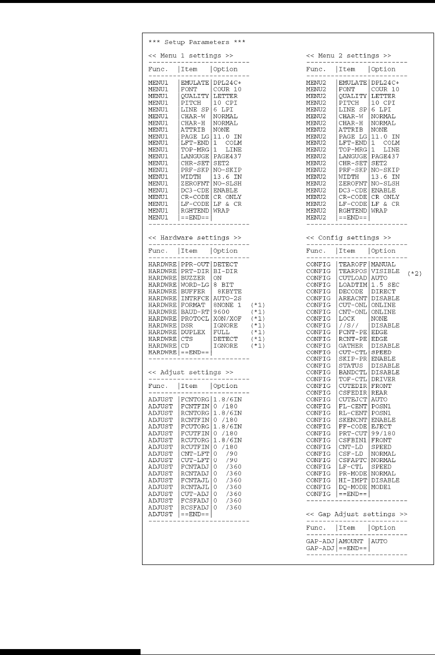
USING SETUP MODE
User's Manual 5-9
*1 FORMAT to CD are not printed when PARALEL option is selected for
INTRFCE.
It is printed equipped with RS-232C.
*2 TEAR-EN is printed when AUTO option is selected for TEAROFF.
Printout of factory defaults using LIST
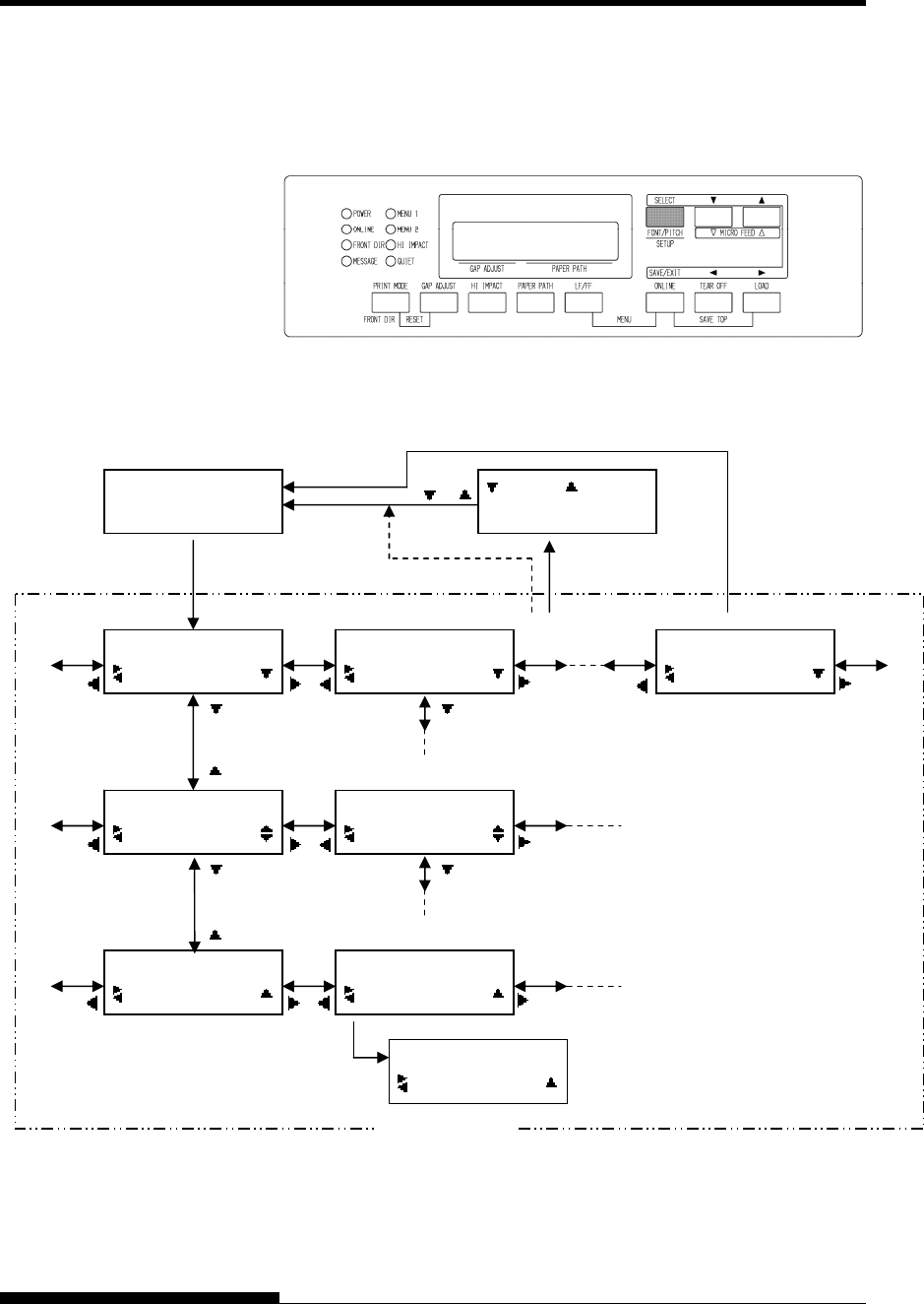
USING SETUP MODE
5-10 User's Manual
To enter setup mode, follow these steps:
1. Press the ONLINE button to place the printer offline.
2. Press the SETUP button until the printer beeps.
Entering setup mode
3. When the printer enters offline setup mode, LCD display shall
change as follows.
Transition of LCD SETUP MODE
ENTERING SETUP
MODE(LCD)
OFFLINE
AUTO TRACTOR F
SETUP MODE
MENU1
SETUP MODE
MENU2
SETUP MODE
SELFDIAGNOSTIC
MENU1
EMULATE
EMULATE
*DPL24C+
:SAVE :CANCEL
MENU1
FONT
EMULATE
XL24E
EMULATE
*XL24E
SELECT button
SETUP button SAVE/EXIT button
SETUP MENU
“*” is applied to a selected option.
or ONLINE button
When online button is pressed
during self diagnostic printing.
Printer stops printing, save
changes and becomes online.
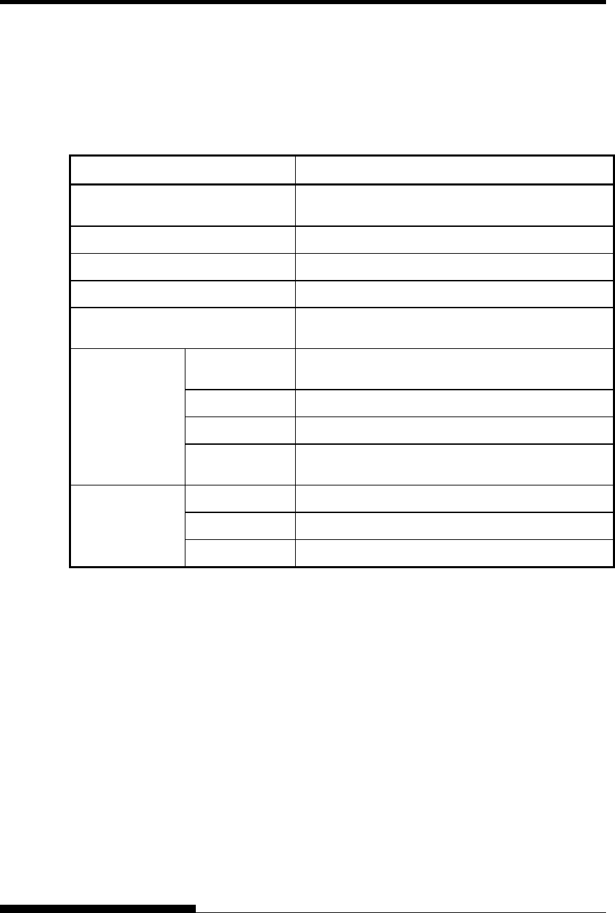
USING SETUP MODE
User's Manual 5-11
Available functions of LCD types SETUP MODE are as follows.
Table 5.2 summarizes the purpose of each function.
Table 5.2 Setup Mode Functions(LCD)
Function Purpose
MENU1 and MENU2 Assigns print features to MENU1 and MENU2 on the
printer control panel.
HARDWRE Changes the printer hardware options.
ADJUST Changes the print position adjustment options.
CONFIG Changes the configuration options.
GAP-ADJ Adjust the gap between the print head and printing
paper.
SAVE&EXIT Exits setup mode and saves any changes made while
in setup mode.
LIST Prints a list of all currently selected options.
DEFAULT Resets factory defaults in MENU1 and MENU2.
SUB FUNCTION
INITIAL Resets factory defaults in MENU1, MENU2,
HARDWRE, ADJUST, CONFIG, GAP-ADJ.
SELF-TST Runs the self-test.
HEX-DUMP Prints hex dumps.
SELFDIAGNOSTIC
V-ALMNT Checks and corrects vertical print alignment.
Detail of selecting items and options are almost same as LED type.
General difference of LCD type SETUP MODE is only SETUP method.
The LIST function prints a list of all the printer’s currently selected
options. This function is useful for checking the printer settings when
you first enter setup mode or just before you exit. To print a list of
options, load paper A4 size or more in advance and select list function.
Note
If paper runs out only LOAD button is available.
OVERVIEW OF
SETUP MODE (LCD)
PRINTING A LIST OF
SELECTED
OPTIONS(LCD)
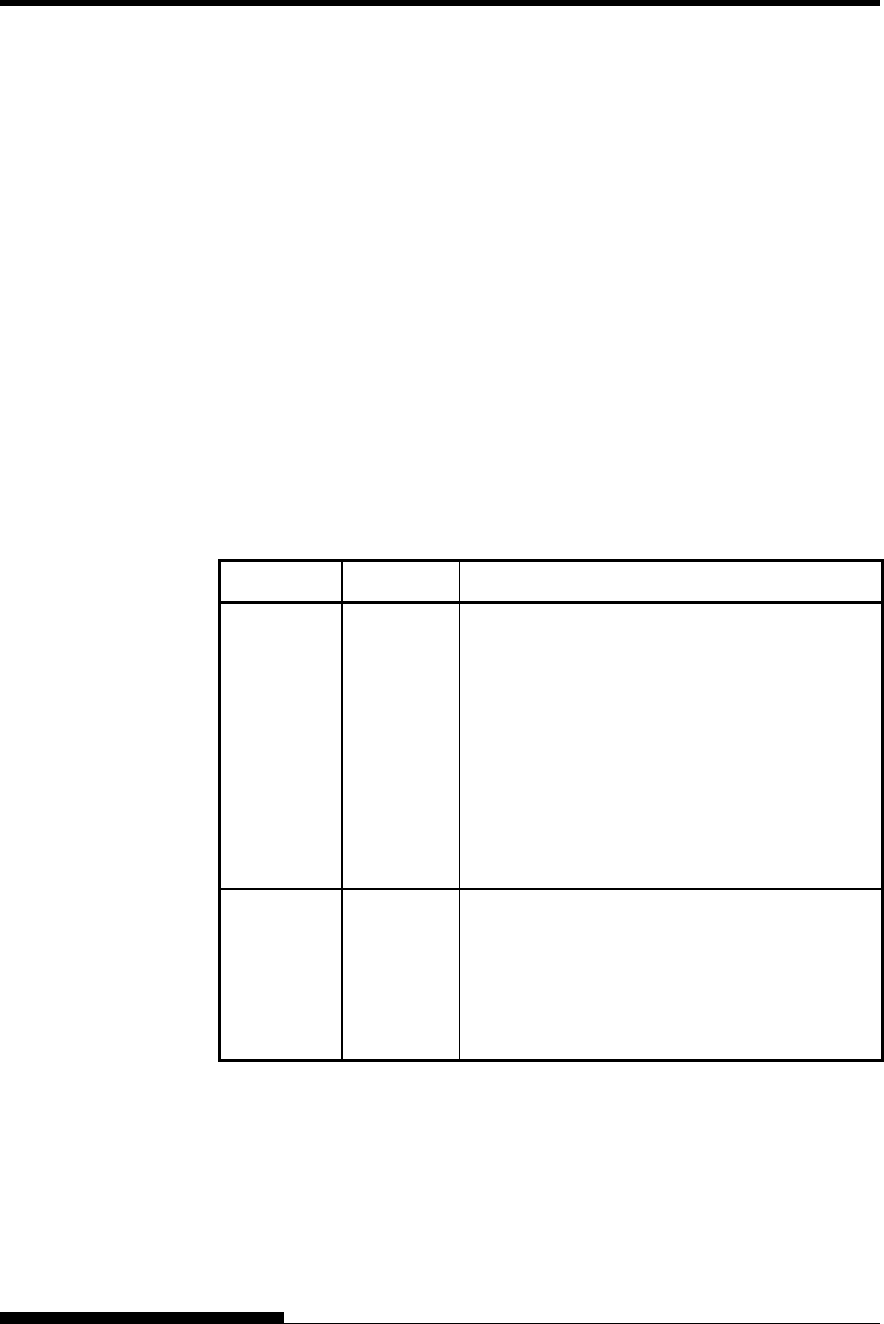
USING SETUP MODE
5-12 User's Manual
The previous page shows a printout of the printer’s factory default
settings. In this printout, options are listed by functional group:
• Menu 1 settings (MENU1 function)
• Menu 2 settings (MENU2 function)
• Hardware settings (HARDWRE function)
• Print position adjustment settings (ADJUST function)
• Configuration settings (CONFIG function)
• Print head gap adjustment settings (GAP-ADJ function)
Most selectable options only alter print features, such as the typestyle,
and page format. However, some options must be selected correctly for
the printer to work properly with your hardware and software.
For each function, Table 5.3 lists items whose options must be selected
correctly for system and printer accessory compatibility.
Table 5.3 Required Options
Function Item Option
MENU1 EMULATE The emulation selected on the printer must be the
same as the emulation selected in your software.
If you selected an emulation when you set up the
printer (Chapter 2), you do not need to change the
EMULATE option unless you want to change to
a different emulation. The emulation assigned to
MENU1 is the default when you turn the printer
on.
See the section MENU1 and MENU2 Items and
Options later in this chapter.
MENU2 None If you use MENU2, the emulation selected for
MENU 2 must be the same as the emulation
selected in your software.
See the section MENU1 and MENU2 Items and
Options later in this chapter.
DECIDING WHICH
OPTIONS TO
CHANGE
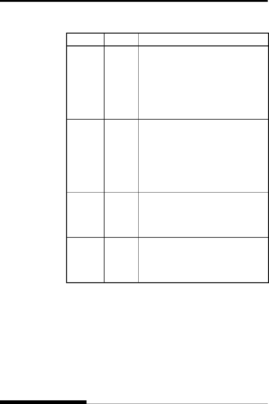
USING SETUP MODE
User's Manual 5-13
Table 5.3 Required Options (Cont.)
Function Item Option
HARDWRE FORMAT
BAUD-RT
PROTOCL
DSR
DUPLEX
CTS
CD
If you have a serial interface, the serial interface
options selected on the printer must be the same
as the settings you selected using your software or
your computer operating system. If the settings
are not the same, the printer will not print or will
print garbage.
See the section Hardware Items and Options
later in this chapter.
ADJUST None If you are not using software to specify the top
margin of the page, use the printer’s default top-
of-form setting, 1 inch (25.4 mm) from the top of
the paper. If you are using software to specify the
top margin of the page, change the default setting
to 1/6 inch (4.2 mm).
See the section Print Position Adjustment Items
and Options later in this chapter.
CONFIG None You can change the printer’s primary
configuration.
See the section Configuration Items and
Options later in this chapter.
GAP-ADJ None If you adjust the gap manually or fix the gap,
change the setting.
See the section Print Head Gap Adjustment
Items and Options.

USING SETUP MODE
5-14 User's Manual
The MENU1 and MENU2 functions allow you to change the print
options assigned to MENU1 and MENU2 on the printer control panel.
In normal (nonsetup) mode, you can easily switch between the menus
for printing, as described in Chapter 4.
MENU1 is invoked when you first turn the printer on.
Select the same emulation on the printer as is selected in your software.
If the emulations are not the same, the printer will not work correctly
with your software. If you plan to use two different emulations on a
regular basis, assign the most frequently used emulation to MENU1.
Assign the second emulation to MENU2. All of the other settings
available for MENU1 and MENU2 are optional. Some of the items and
options will vary with the emulation.
To determine which features your software supports, refer to your
software documentation.
Table 5.4 describes the MENU1 and MENU2 items and options. Both
functions offer the same items and options. The items in Table 5.4 are
listed in the order in which they are printed. Not all items are defined for
all emulations and some options vary with the emulation.
The procedure for changing the options is referred to in the section Setup
Mode Example.
MENU1 AND MENU2
ITEMS AND
OPTIONS
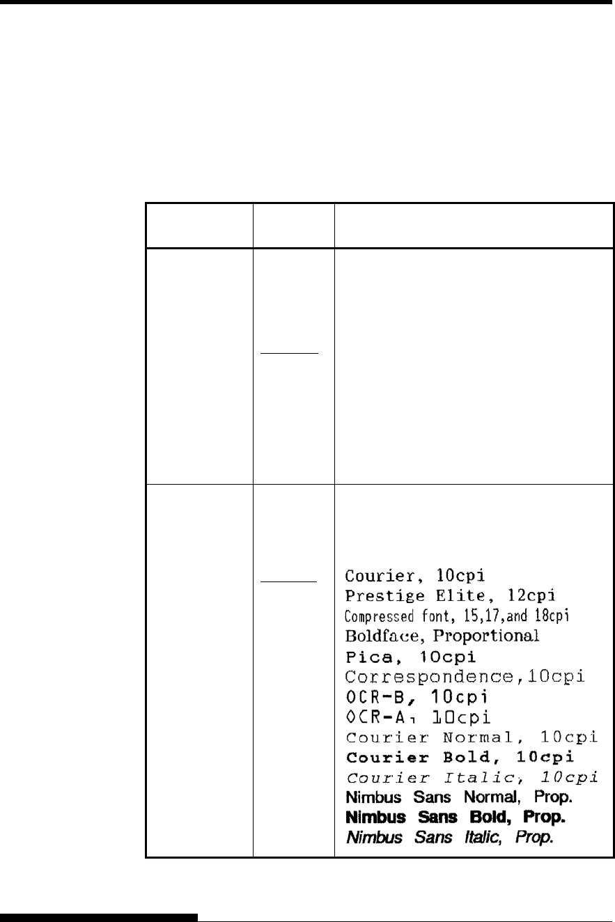
USING SETUP MODE
User's Manual 5-15
Table 5.4 MENU1 and MENU2 Items and Options
NOTES:
• Underlined options are the factory defaults.
• Asterisks identify items and options that differ for the IBM XL24E
and Epson ESC/P2 emulations. The notes are defined at the end of
the table.
MENU1 and
MENU2 Items Options Description
<EMULATE> Select the same emulation as is selected in
your software. See the section Selecting an
Emulation in Chapter 2 for information on
selecting an emulation.
DPL24C+ Fujitsu DL-series printers
(DPL24C PLUS command set)
XL24E
ESC/P2
IBM Proprinter XL24E printers Epson printers
using the ESC/P2 command set
NOTE: When you change the emulation, all
MENU1 or MENU2 options are reset to the
factory defaults for that emulation.
<FONT>
COUR 10
PRSTG12
COMPRSD
BOLDFCE
PICA 10
CORRESP
OCR-B
OCR-A
COUR-N
COUR-B
COUR-I
N.SAN-N
N.SAN-B
N.SAN-I
For each of the following fonts, the
recommended pitch settings are given after the
font name. When you change the font, be sure
to also change the pitch, if required.
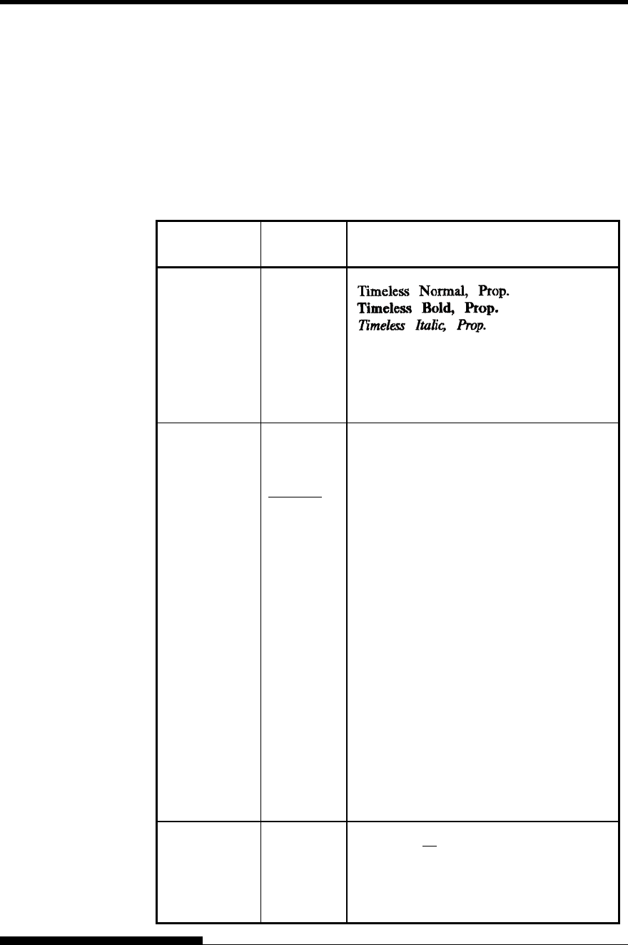
USING SETUP MODE
5-16 User's Manual
Table 5.4 MENU1 and MENU2 Items and Options (Cont.)
NOTES:
• Underlined options are the factory defaults.
• Asterisks identify items and options that differ for the IBM XL24E
and Epson ESC/P2 emulations. The notes are defined at the end of
the table.
MENU1 and
MENU2 Items Options Description
<FONT>
(continued)
TIMLS-N
TIMLS-B
TIMLS-I
DOWNLD# Font 0 or font 1 in the printer’s download
RAM
See Appendix F for font examples.
<QUALITY> Select the print quality that most often meets
your needs.
LETTER Letter print quality. This option provides the
highest resolution but the slowest print
speed. It cannot be used with the
compressed font.
REPORT Report print quality. This option provides
lower resolution than letter quality, but at
twice the speed. If you want only the double
speed, regardless of fonts, use the
correspondence font. The quality of the
correspondence font is higher than that of
report.
DRAFT Regular draft print quality. This option
provides lower resolution than report
quality, but at 3 times letter speed.
HI-DRFT High-speed draft print quality. This option
provides lower resolution than draft quality,
but at 4 times letter speed.
<PITCH> ## CPI 2.5, 3, 5, 6, 10, 12, 15, 17, 18, or 20 cpi
(characters per horizontal inch)
PROP SP Proportional spacing (1/12 inch per
character space)
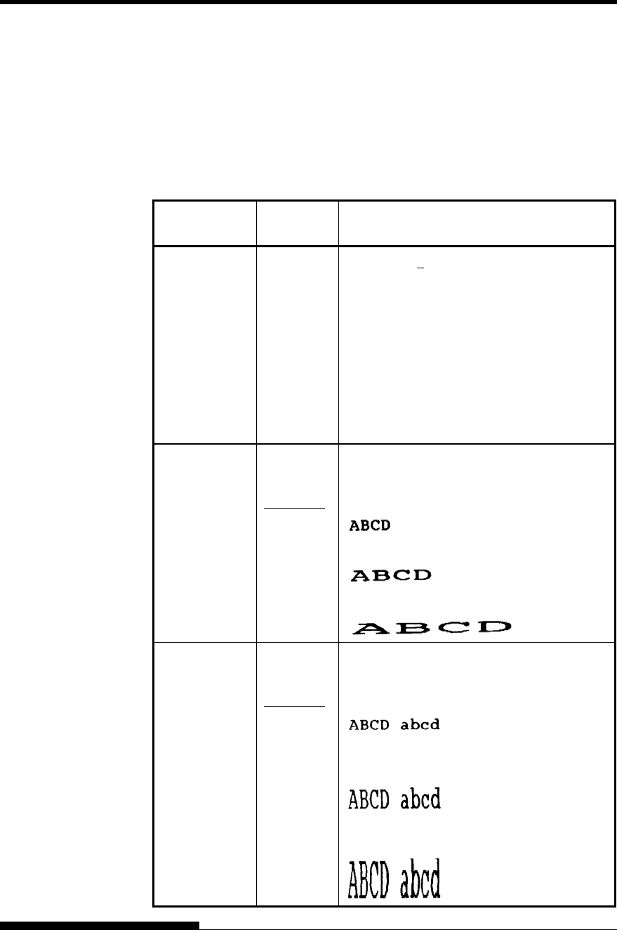
USING SETUP MODE
User's Manual 5-17
Table 5.4 MENU1 and MENU2 Items and Options (Cont.)
NOTES:
• Underlined options are the factory defaults.
• Asterisks identify items and options that differ for the IBM XL24E
and Epson ESC/P2 emulations. The notes are defined at the end of
the table.
MENU1 and
MENU2 Items Options Description
<LINE SP> ## LPI 1, 2, 3, 4, 5, 6, 7, or 8 lpi
(lines per vertical inch)
6 lpi 3 lpi (double spacing)
ABCD ABCD
ABCD
ABCD ABCD
ABCD
ABCD ABCD
ABCD
<CHAR-W> Change also the pitch 2 TIMES or 4 TIMES
is selected.
NORMAL Standard character width
2 TIMES Double character width
4 TIMES
(*1)
Quadruple character width
<CHAR-H> Change also the line spacing if 2 TIMES or 4
TIMES is selected.
NORMAL Standard character height
2 TIMES Double character height
4 TIMES
(*1)
Quadruple character height
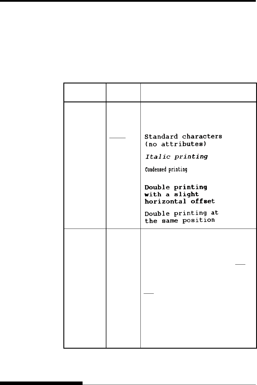
USING SETUP MODE
5-18 User's Manual
Table 5.4 MENU1 and MENU2 Items and Options (Cont.)
NOTES:
• Underlined options are the factory defaults.
• Asterisks identify items and options that differ for the IBM XL24E
and Epson ESC/P2 emulations. The notes are defined at the end of
the table.
MENU1 and
MENU2 Items Options Description
<ATTRIB> Selects an attribute to add emphasis to your
documents.
Only one attribute may be selected at a time.
NONE
ITALICS
CONDNSD
(*1)
SHADOW
BOLD
<PAGE LG> Specifies the length of the page in inches.
## IN
For DPL24C PLUS and IBM XL24E
emulations:
3.0, 3.5, 4.0, 5.0, 5.5, 6.0, 7.0, 8.0, 8.5, 11.0
(letter size), 11.6 (A4 size), 12.0, 14.0, 18.0
inches, or LINE
For Epson ESC/P2 emulation: 4.0, 4.5, 5.0, ...,
11.0, 11.5, ..., 22.0 inches
LINE
Selecting the page length by specifying
number of lines per page (default: 66 lines per
page) Selecting this option displays the <PG
LX10> and <PG LX1>. Use in combination
the <PG LX10> to set the tens value of the
lines-per-page setting, and the <PG LX1> to
set the ones value of the lines-per-page setting.
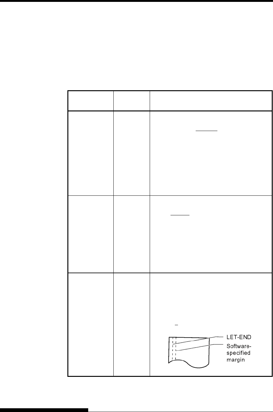
USING SETUP MODE
User's Manual 5-19
Table 5.4 MENU1 and MENU2 Items and Options (Cont.)
NOTES:
• Underlined options are the factory defaults.
• Asterisks identify items and options that differ for the IBM XL24E
and Epson ESC/P2 emulations. The notes are defined at the end of
the table.
MENU1 and
MENU2 Items Options Description
<PG LX10> Tens value
setting for
setting
number of
lines per
page
0 LINE, 10 LINE, 20 LINE, 30 LINE 40
LINE, 50 LINE, 60 LINE, 70 LINE 80 LINE,
90 LINE
• The LINE setting depends on the line
spacing setting 'LINE SP'.
• When 0 LINE is set, the line spacing
value is 11.0 IN (only when both 'PG
LX10' = '0 LINE' and 'PG LX1' = '0
LINE' are set).
<PG LX1> Ones value
setting for
setting
number of
lines per
page
0 LINE, 1 LINE, 2 LINE, 3 LINE 4 LINE, 5
LINE, 6 LINE, 7 LINE 8 LINE, 9 LINE
• The LINE setting depends on the line
spacing setting 'LINE SP'.
• When 0 LINE is set, the line spacing
value is 11.0 IN (only when both 'PG
LX10' = '0 LINE' and 'PG LX1' = '0
LINE' are set).
<LFT-END> Specifies the print start column for changing
the left margin. Printing starts at the position
given by this column plus your software-
specified left margin.
## COLM Column 1, 2, 3, ..., 41
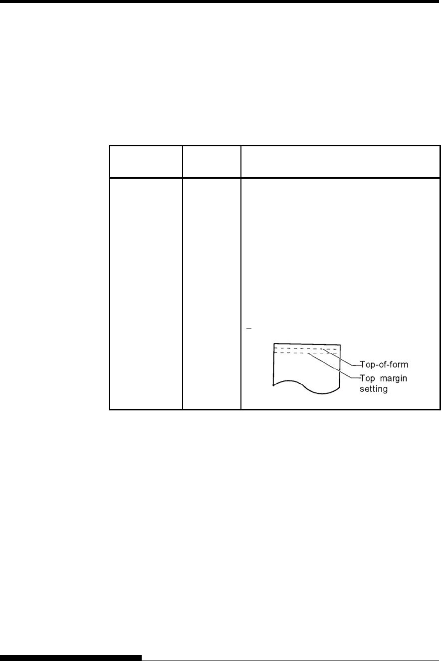
USING SETUP MODE
5-20 User's Manual
Table 5.4 MENU1 and MENU2 Items and Options (Cont.)
NOTES:
• Underlined options are the factory defaults.
• Asterisks identify items and options that differ for the IBM XL24E
and Epson ESC/P2 emulations. The notes are defined at the end of
the table.
MENU1 and
MENU2 Items Options Description
<TOP-MRG> Specifies the number of space lines for the top
margin. The resultant blank space is the
<TOP-MRG> setting minus 1 line.
The total size of your top margin is the above
resultant value plus the following two settings:
top-of-form (default = 1 inch) and the
software-specified top margin. If you are using
software to specify the top margin, use the
default (1 line) for <TOP-MRG>.
## LINE 1, 2, 3,4, 5, 6, 7, 8, 9, or 10 lines
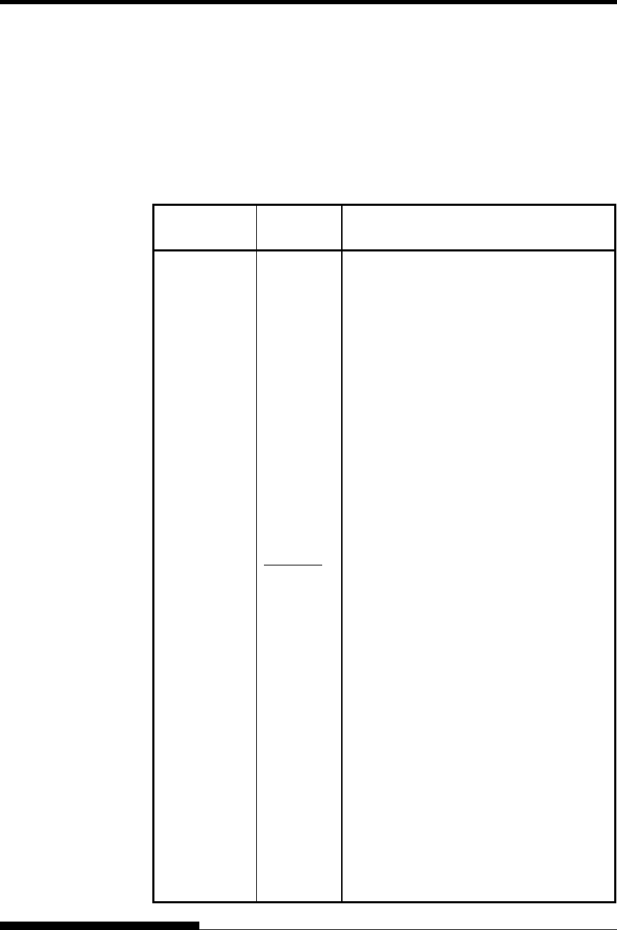
USING SETUP MODE
User's Manual 5-21
Table 5.4 MENU1 and MENU2 Items and Options (Cont.)
NOTES:
• Underlined options are the factory defaults.
• Asterisks identify items and options that differ for the IBM XL24E
and Epson ESC/P2 emulations. The notes are defined at the end of
the table.
MENU1 and
MENU2 Items Options Description
<LANGUGE> Selects a language. Appendix E shows the
character sets for each language.
Two-pass means that diacritical marks are
printed separately from their letters and that
letters are printed without any reduction.
The first listing is common to all emulations.
Options specific to each emulation are
skipped. See the subsequent listings (*2)
and(*3).
USA
American English
(Same as code page 437)
UK British English
GERMAN German
SWEDISH Swedish
PAGE437 Code page 437
PAGE850 Code page 850
PAGE860 Code page 860
PAGE863 Code page 863
PAGE865 Code page 865
ECMA94 ECMA 94
ISO8859 ISO 8859-1
PG852 Code page 852
PG852-T Code page 852 two-pass
PG855 Code page 855
PG866 Code page 866
HUNGARY Hungarian
HUNG-T Hungarian two-pass
USING SETUP MODE
5-22 User's Manual
Table 5.4 MENU1 and MENU2 Items and Options (Cont.)
NOTES:
• Underlined options are the factory defaults.
• Asterisks identify items and options that differ for the IBM XL24E
and Epson ESC/P2 emulations. The notes are defined at the end of
the table.
MENU1 and
MENU2 Items Options Description
SLOV Slovenian <LANGUGE>
(continued) SLOV-T Slovenian two-pass
POLISH Polish
POLSH-T Polish two-pass
MAZOWIA Mazowian
MAZOW-T Mazowian two-pass
LATIN2 Latin 2
LATIN2-T Latin 2 two-pass
KAMENIC Kamenicky
KAMEN-T Kamenicky two-pass
TURKY Turkish
TURKY-T Turkish two-pass
CYRILIC Cyrillic
IBM437 IBM 437
IBM851 IBM 851
ELOT928 ELOT 928
PG-DHN Code page DHN
LATIN-P Latin Polish
ISO-LTN ISO Latin
LITHUA1 Lithuanian1
LITHUA2 Lithuanian2
MIK
MACEDON Macedonian
PG-MAC
ELOT927

USING SETUP MODE
User's Manual 5-23
Table 5.4 MENU1 and MENU2 Items and Options (Cont.)
NOTES:
• Underlined options are the factory defaults.
• Asterisks identify items and options that differ for the IBM XL24E
and Epson ESC/P2 emulations. The notes are defined at the end of
the table.
MENU1 and
MENU2 Items Options Description
ABG
<LANGUGE>
(continued) ABY
DEC GR
HBR-OLD
PG862
HBR-DEC
GREEK 11
ISO-TUK ISO Turkish
RUSCII
LATIN-9
WCP1250 Windows-1250
WCP1251 Windows-1251
WCP1252 Windows-1252
(*2)
FRENCH French
ITALIAN Italian
SPANISH Spanish
DANISH1 Danish I
DANISH2 Danish II
FINNISH Finnish
NORWEGN Norwegian
USING SETUP MODE
5-24 User's Manual
Table 5.4 MENU1 and MENU2 Items and Options (Cont.)
NOTES:
• Underlined options are the factory defaults.
• Asterisks identify items and options that differ for the IBM XL24E
and Epson ESC/P2 emulations. The notes are defined at the end of
the table.
MENU1 and
MENU2 Items Options Description
<LANGUGE>
(continued) DANISH1 Danish I
ITALIAN Italian
SPANSH1 Spanish I
SPANSH2 Spanish II
JAPAN Japanese
NORWEGN Norwegian
LATIN A Latin American
FRENCH French
DANISH2 Danish II
KOREA Korea
LEGAL Legal
<CHR-SET> (*2)
SET 1
IBM character set 1
SET 2 IBM character set 2
If a downloaded (soft) font is used, the
character set for that font overrides the
<CHR-SET> setting.
(*3)
ITALIC Italic characters are available.
GRAPHIC
Graphics characters (ruled lines) are
available.
USING SETUP MODE
User's Manual 5-25
Table 5.4 MENU1 and MENU2 Items and Options (Cont.)
NOTES:
• Underlined options are the factory defaults.
• Asterisks identify items and options that differ for the IBM XL24E
and Epson ESC/P2 emulations. The notes are defined at the end of
the table.
MENU1 and
MENU2 Items Options Description
For continuous forms, this option specifies
whether an inch is skipped around the
perforation. If you are not using software to
specify a bottom margin, select SKIP when
using thicker, multipart forms.
<PRF-SKP>
SKIP One inch is skipped around the perforation.
NO-SKIP The perforation is not skipped. Printing
continues in the bottom margin of the page.
<WIDTH> 13.6 IN 13.6-inch page width
11.4 IN 11.4-inch page width
11.0 IN 11-inch page width
8.0 IN 8-inch page width
<ZEROFNT>
(*2)
Specifies whether to print the number zero
with a slash. This is useful to distinguish the
capital letter “O” from the number “0”.
Invalid for some soft fonts.
NO-SLSH 0
SLASH 0
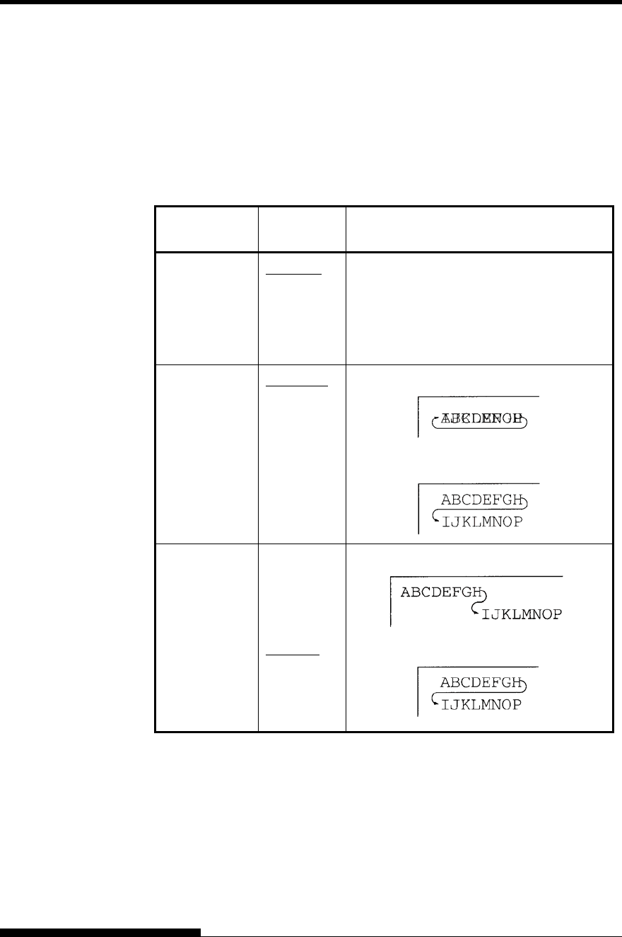
USING SETUP MODE
5-26 User's Manual
Table 5.4 MENU1 and MENU2 Items and Options (Cont.)
NOTES:
• Underlined options are the factory defaults.
• Asterisks identify items and options that differ for the IBM XL24E
and Epson ESC/P2 emulations. The notes are defined at the end of
the table.
MENU1 and
MENU2 Items Options Description
ENABLE Enables the DC1 and DC3 codes.
Any data received between DC3 and the
next DC1 is ignored.
<DC3-CDE>
(*4)
DISABLE Disables the DC1 and DC3 codes. These
codes are then ignored.
<CR-CODE> CR ONLY No line feed is added to a carriage return.
CR & LF A line feed is added to each carriage return.
<LF-CODE>
(*2)
LF ONLY No carriage return is added to a line feed.
LF & CR A carriage return is added to each line feed.
Note
The default value of <LF-CODE> changes with the selected emulations as
follows.
"LF&CR" is a default value in the DPL24C+ emulations.
"LF ONLY" is a default value in the XL24E emulations.
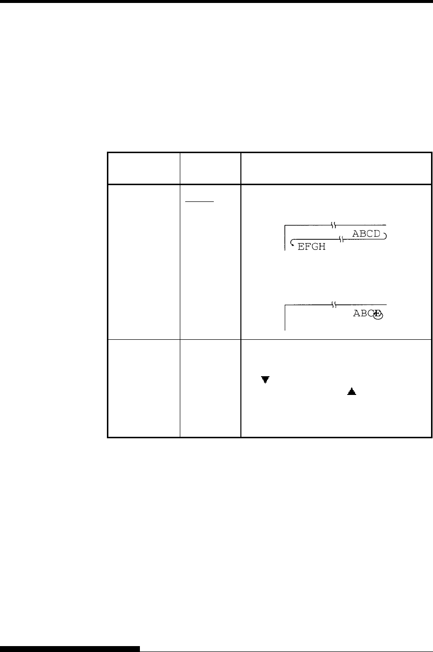
USING SETUP MODE
User's Manual 5-27
Table 5.4 MENU1 and MENU2 Items and Options (Cont.)
NOTES:
• Underlined options are the factory defaults.
• Asterisks identify items and options that differ for the IBM XL24E
and Epson ESC/P2 emulations. The notes are defined at the end of
the table.
MENU1 and
MENU2 Items Options Description
WRAP End-of-line wrap. Causes a carriage return
plus a line feed.
<RGHTEND>
OVR-PRT Characters are overprinted at the end of a
line.
<==END==> (LED only)
Indicates the end of MENU1 items. Press
the button to print the first item,
<EMULATE>. Press the button to print
the previous item, <RGHTEND>. Press the
ONLINE button to reprint the
<<FUNCTION>> menu.
*1 Unavailable in the IBM XL24E emulation
*2 Unavailable in the Epson ESC/P2 emulations
*3 Available only in the Epson ESC/P2 emulations
*4 Available only in the DPL24C+ emulation
USING SETUP MODE
5-28 User's Manual
Resetting MENU1 and MENU2
To reset the factory defaults for both MENU1 and MENU2, select the
DEFAULT/INITIAL function. For more information, see the section
Resetting Defaults later in this chapter. The DEFAULT function cannot
reset those options which are handled by the HARDWRE, ADJUST,
CONFIG, and GAP-ADJ functions. The INITIAL function can reset
those options which are handled by the HARDWRE, ADJUST, CONFIG,
and GAP-ADJ functions.
The HARDWRE function defines the printer’s hardware operating
conditions. If you are using the optional RS-232C serial interface,
the serial interface options must be set properly for the printer to
function correctly with your system hardware.
Table 5.5 describes the HARDWRE items and options. Items are
listed in the order in which they are printed. The procedure for changing
the hardware options is described after Table 5.5.
Table 5.5 HARDWRE Items and Options
NOTE: Underlined options are the factory defaults.
HARDWRE
Items Options Description
<PPR-OUT> Specifies how the printer responds when you
run out of paper.
CNTONLY The printer detects paper-out only for
continuous forms. Printing stops and the
PAPER OUT indicator lights red.
DETECT The printer detects paper-out for both
continuous forms and single sheets. Printing
stops and the PAPER OUT indicator lights
red.
IGNORE The printer ignores paper-out for both
continuous forms and single sheets. Printing
continues until no more data remains. No
PAPER OUT warning is displayed.
CHANGING
HARDWARE
OPTIONS
USING SETUP MODE
User's Manual 5-29
Table 5.5 HARDWRE Items and Options (Cont.)
NOTE: Underlined options are the factory defaults.
HARDWRE
Items Options Description
<PRT-DIR> BI-DIR Bidirectional printing. The printer prints in
either direction while seeking the next print
direction for a shorter print time.
UNI-DIR
Unidirectional printing. Unidirectional
printing is used for printing vertical lines in
tables even if vertical alignment is not
adjusted. Unidirectional printing is slower
than bidirectional printing.
<BUZZER> Enables or disables the printer status buzzer.
ON Buzzer on (recommended).
The printer beeps to indicate paperout or
other conditions.
OFF Buzzer off under any conditions.
<WORD-LG> To determine the required word length, refer
to your computer documentation. Select 8-
BIT to print bit image graphics.
8 BIT 8-bit word length (used by most computers)
7 BIT 7-bit word length (MSB = 0)
<BUFFER> Assigns buffer memory to input data and
downloaded font data.
Print buffer Download buffer
NONE 0 byte 128K bytes
256BYTE 256 bytes 127.75K bytes
2KBYTE 2K bytes 126K bytes
8KBYTE 8K bytes 120K bytes
24KBYTE 24K bytes 104K bytes
32KBYTE 32K bytes 96K bytes
96KBYTE 96K bytes 32K bytes
128KBYT 128K bytes 0K bytes
USING SETUP MODE
5-30 User's Manual
Table 5.5 HARDWRE Items and Options (Cont.)
NOTE: Underlined options are the factory defaults.
HARDWRE
Items Options Description
<BUFFER>
(continued)
NOTE:
• 0BYTE option is recommended only
for graphics application.
• With 128KB selected, the printer
cannot accept any download font data.
<INTRFCE> Selects the type of the interface to the
computer.
PARALEL Centronics parallel interface
SERIAL RS-232C serial interface
USB USB interface
AUTO-2S Auto interface selection mode
AUTO-4S
AUTO-6S
• Both interfaces are ready for
communication.
AUTO10S
AUTO15S
• Specify the timing regarding the selected
interface as being inactive.
AUTO20S
To switch the interface to the optional LAN
interface, mount the LAN card with the setup
mode set to “AUTO-XS” or “AUTOXXS”
under “INTERFCE,” which in turn is under
“HARDWRE” The interface will
automatically switch to the optional LAN
interface.
To switch the interface to something other
than the optional LAN interface, do either of
the following:
• To return the setup mode to
“INTERFCE” under “HARDWRE,”
remove the LAN card.
• To switch the interface to a fixed
interface, set PARALEL,USB with the
LAN card mounted, and the setup mode
set to “INTERFCE” under
“HARDWRE.”
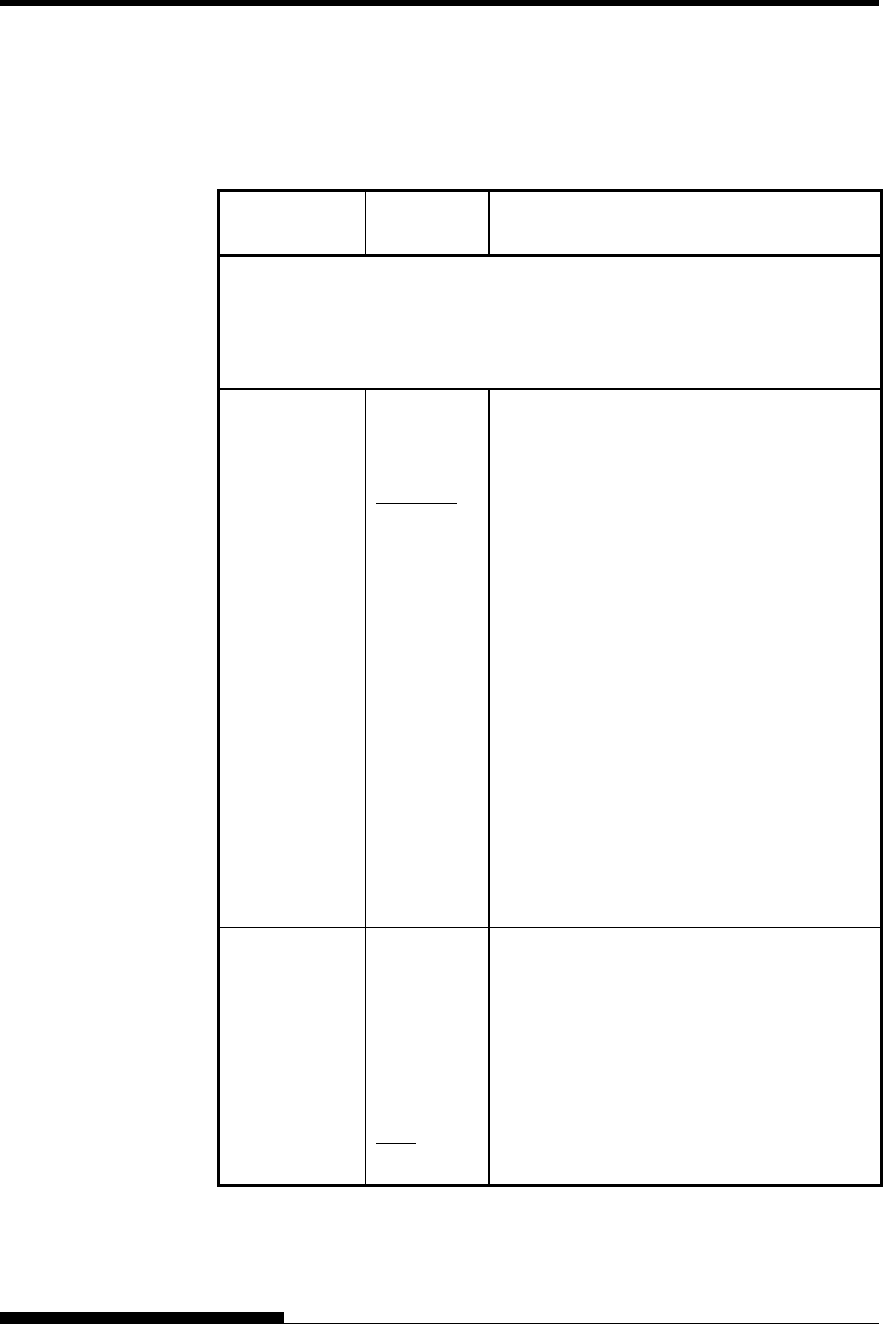
USING SETUP MODE
User's Manual 5-31
Table 5.5 HARDWRE Items and Options (Cont.)
NOTE: Underlined options are the factory defaults.
HARDWRE
Items Options Description
Serial Interface or USB interface Items. The following <FORMAT> to
<DUPLEX> items are not printed when you select the PARALEL option for
the <INTRFCE> item. Be sure that the options selected on the printer are the
same as the options selected using your computer operating system or your
software. Refer to the documentation provided for your computer and software.
<FORMAT> Number
of data
bits
Parity bit Number of stop
bits
8NONE 1 8 None 1
8NONE 2 8 None 2
8EVEN 1 8 Even 1
8ODD 1 8 Odd 1
7EVEN 1 7 Even 1
7ODD 1 7 Odd 1
7MARK 1 7 Mark 1
7SPACE 1 7 Space 1
7EVEN 2 7 Even 2
7ODD 2 7 Odd 2
The data format also includes a start bit. The
mark is logical 1. The space is logical 0.
<BAUD-RT> 150
300
600
1200
2400
4800
9600
19200
The baud rate is in bps (bits per second).
Select the same baud rate as 600 used by your
computer or modem.

USING SETUP MODE
5-32 User's Manual
Table 5.5 HARDWRE Items and Options (Cont.)
NOTE: Underlined options are the factory defaults.
HARDWRE
Items Options Description
<PROTOCL> Indicates data transmission protocol.
XON/XOF The DC1 and DC3 codes are used.
DTR The Data Terminal Ready signal is used.
REV-CHL The Reverse Channel signal is used.
<DSR> IGNORE DSR is ignored by the printer.
DETECT DSR is detected by the printer.
<DUPLEX> FULL Simultaneous data transmission occurs in
opposite directions.
HALF
Data transmission occurs in either direction,
but not simultaneously.
<CTS> IGNORE CTS is ignored by the printer.
DETECT CTS is detected by the printer.
<CD> IGNORE CD is ignored by the printer.
DETECT CD is detected by the printer.
<==END==> Indicates the end of the HARDWRE item
list. Press the button to print the first item,
which is <PPR-OUT>.
Press the button to print the previous item.
Press the ONLINE button to reprint the
<<FUNCTION>> menu.

USING SETUP MODE
User's Manual 5-33
When you print using ruled paper, you often want to adjust the print
position so that the print sits properly on the ruled lines. The ADJUST
function allows you to:
• Set top-of-form position
• Fine-tune top-of-form position
• Fine-tune left print start column (left margin)
• Adjust for accumulative line spacing error in a page
The top edge of your paper is the physical top of the page. The logical
top of the page, as “understood” by the printer when loading paper, is
called the top-of-form. Printing starts at this position. Note that printing
actually starts at the position obtained by adding the following:
• Top-of-form, default = 1.8/6 inch (7.6mm)
• Top margin specified by your software
• Printer TOP-MRG (top margin setting), default = 1 line
Table 5.6 describes the ADJUST items and options. Items are listed in
the order they are printed. The procedure for changing top-of-form is
described after Table 5.6.
CHANGING PRINT
POSITION
ADJUSTMENT
OPTIONS
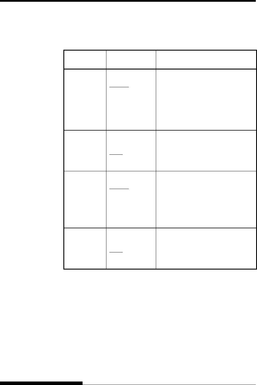
USING SETUP MODE
5-34 User's Manual
Table 5.6 ADJUST Items and Options
NOTE: Underlined options are the factory defaults.
HARDWRE
Items Options Description
<FCNTORG> 1/6 IN
1.8/6 IN
:
6/6 IN
:
66/6 IN
Sets the top-of-form for front
continuous forms in increments of 1/6
inch (4.2 mm) from the physical top of
the page.
The default is recommended if your top
margin is not software-specified. A
setting of 1/6 inch is preferable when
your top margin is software-specified.
<FCNTFIN>
0/180, ..., 29/180
Fine-tunes the top-of-form position for
front continuous forms.
Increases top-of-form in increments of
1/180 inch
(0.14 mm).
<RCNTORG> 1/6 IN
1.8/6 IN
:
6/6 IN
:
66/6 IN
Sets the top-of-form for rear continuous
forms in increments of 1/6 inch (4.2
mm) from the physical top of the page.
The default is recommended if your top
margin is not software-specified. A
setting of 1/6 inch is preferable when
your top margin is software-specified.
<RCNTFIN>
0/180, ..., 29/180
Fine-tunes the top-of-form position for
rear continuous forms.
Increases top-of-form in increments of
1/180 inch
(0.14 mm).

USING SETUP MODE
User's Manual 5-35
Table 5.6 ADJUST Items and Options (Cont.)
NOTE: Underlined options are the factory defaults.
HARDWRE
Items Options Description
<FCUTORG> 1/6 IN
1.8/6 IN
:
6/6 IN
:
66/6 IN
Sets the top-of-form for front single
sheets in increments of 1/6 inch (4.2
mm) from the physical top of the page.
The default is recommended if your top
margin is not software-specified. A
setting of 1/6 inch is preferable when
your top margin is software-specified.
<FCUTFIN>
0/180, ..., 29/180
Fine-tunes the top-of-form position for
front single sheets.
Increases top-of-form in increments of
1/180 inch
(0.14 mm).
<RCUTORG> 1/6 IN
1.8/6 IN
:
6/6 IN
:
66/6 IN
Sets the top-of-form for rear single
sheets in increments of 1/6 inch (4.2
mm) from the physical top of the page.
The default is recommended if your top
margin is not software-specified. A
setting of 1/6 inch is preferable when
your top margin is software-specified.
<RCUTFIN>
0/180, ..., 29/180
Fine-tunes the top-of-form position for
rear single sheets.
Increases top-of-form in increments of
1/180 inch
(0.14 mm).
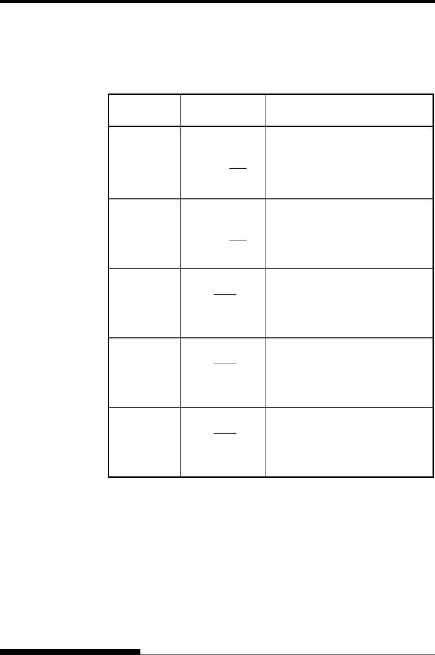
USING SETUP MODE
5-36 User's Manual
Table 5.6 ADJUST Items and Options (Cont.)
NOTE: Underlined options are the factory defaults.
HARDWRE
Items Options Description
<CNT-LFT>
-10/90, ..., 0/90,
..., 10/90
Fine-tunes the left print start position
for continuous forms.
Moves the position left or right in
increments of 1/90 inch
(0.28 mm).
<CUT-LFT>
-10/90, ..., 0/90,
..., 10/90
Fine-tunes the left print start position
for single sheets.
Moves the position left or right in
increments of 1/90 inch
(0.28 mm).
<FCNTADJ> -14/360, -9/360, -
4/360, 0/360
4/360, 9/360,
14/360,
GRAPHIC(*1)
Compensates for the forms feed error
accumulated through feeding of front
continuous forms.
<RCNTADJ> -14/360, -9/360, -
4/360, 0/360
4/360, 9/360,
14/360,
GRAPHIC(*1)
Compensates for the forms feed error
accumulated through feeding of rear
continuous forms.
<FCNTAJL> -14/360, -9/360, -
4/360, 0/360
4/360, 9/360,
14/360,
GRAPHIC(*1)
Compensates for the forms feed error
accumulated through feeding of front
continuous forms. (Last page)
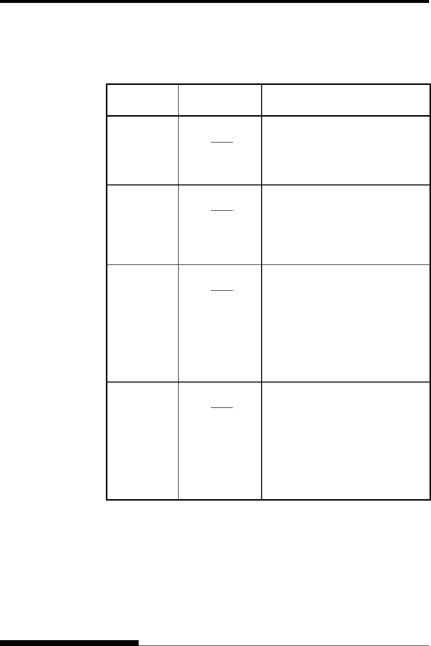
USING SETUP MODE
User's Manual 5-37
Table 5.6 ADJUST Items and Options (Cont.)
NOTE: Underlined options are the factory defaults.
HARDWRE
Items Options Description
<RCNTAJL> -14/360, -9/360, -
4/360, 0/360
4/360, 9/360,
14/360,
GRAPHIC(*1)
Compensates for the forms feed error
accumulated through feeding of rear
continuous forms. (Last page)
<CUT-ADJ> -14/360, -9/360, -
4/360, 0/360
4/360, 9/360,
14/360,
GRAPHIC(*1)
Compensates the line spacing pitch on
the basis of the spacing error
accumulated for feeding single sheets
by10 inches.
Decreases or increases in increments of
1/360 inch in total.
<FCSFADJ> -14/360, -9/360, -
4/360, 0/360
4/360, 9/360,
14/360,
GRAPHIC(*1)
Compensates the line spacing pitch on
the basis of the spacing error
accumulated for feeding single sheets
by10 inches.
Decreases or increases in increments of
1/360 inch in total.
This option is available only when
paper is being loaded in the front cut
sheet feeder.
<RCSFADJ> -14/360, -9/360, -
4/360, 0/360
4/360, 9/360,
14/360,
GRAPHIC(*1)
Compensates the line spacing pitch on
the basis of the spacing error
accumulated for feeding single sheets
by10 inches.
Decreases or increases in increments of
1/360 inch in total.
This option is available only when
paper is being loaded in the rear cut
sheet feeder.
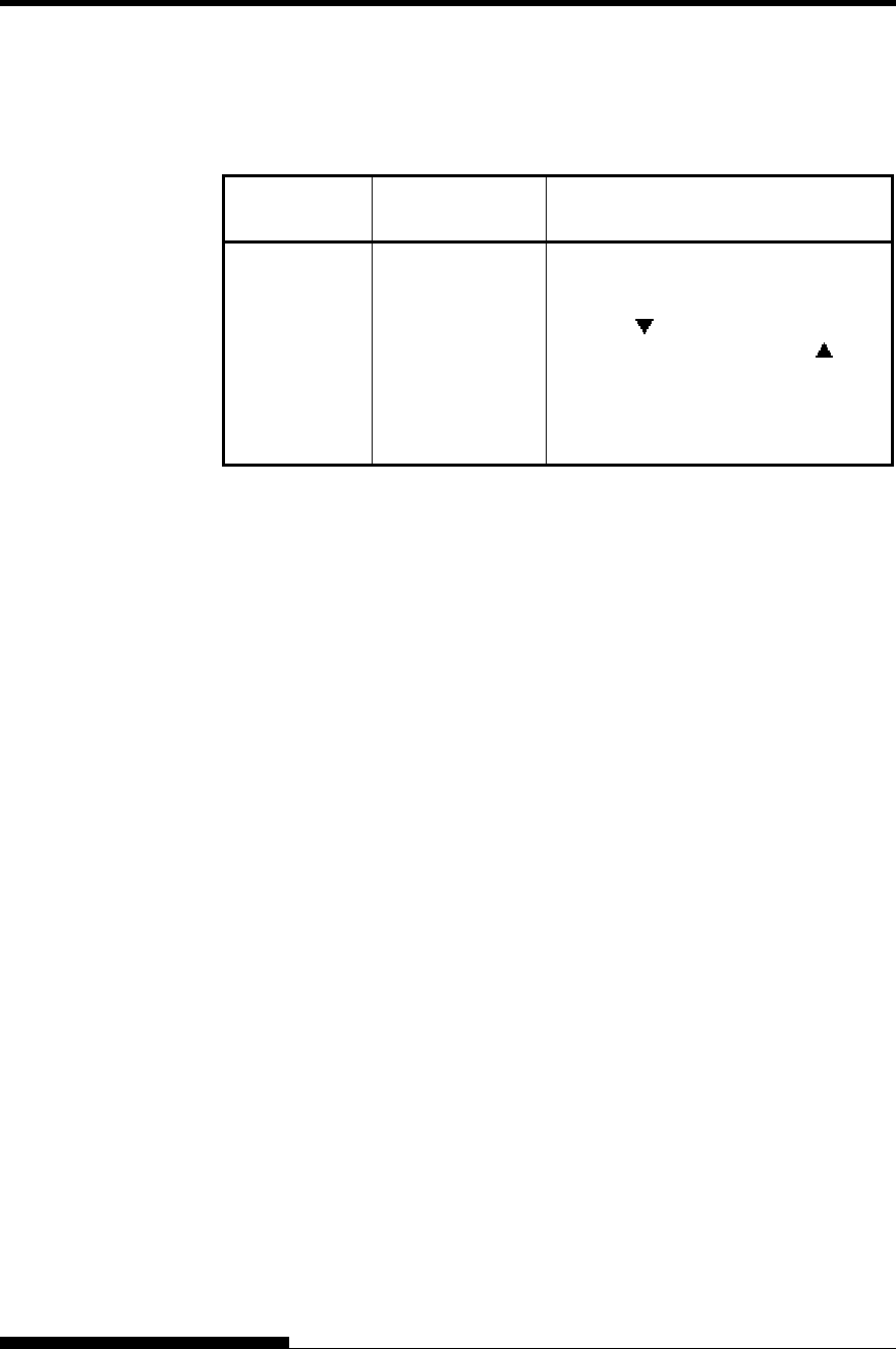
USING SETUP MODE
5-38 User's Manual
Table 5.6 ADJUST Items and Options (Cont.)
NOTE: Underlined options are the factory defaults.
HARDWRE
Items Options Description
<==END==> (LED only)
Indicates the end of MENU1 items.
Press the button to print the first
item, <FCNTORG>. Press the
button to print the previous item,
<RCSFADJ>. Press the ONLINE
button to reprint the <<FUNCTION>>
menu.
*1: When printing graphics, selecting “GRAPHIC” may result in the
printing of clearer graphics.
The CONFIG function defines the printer’s primary configuration. You
can set the following options to ensure that the printer meets your
requirements:
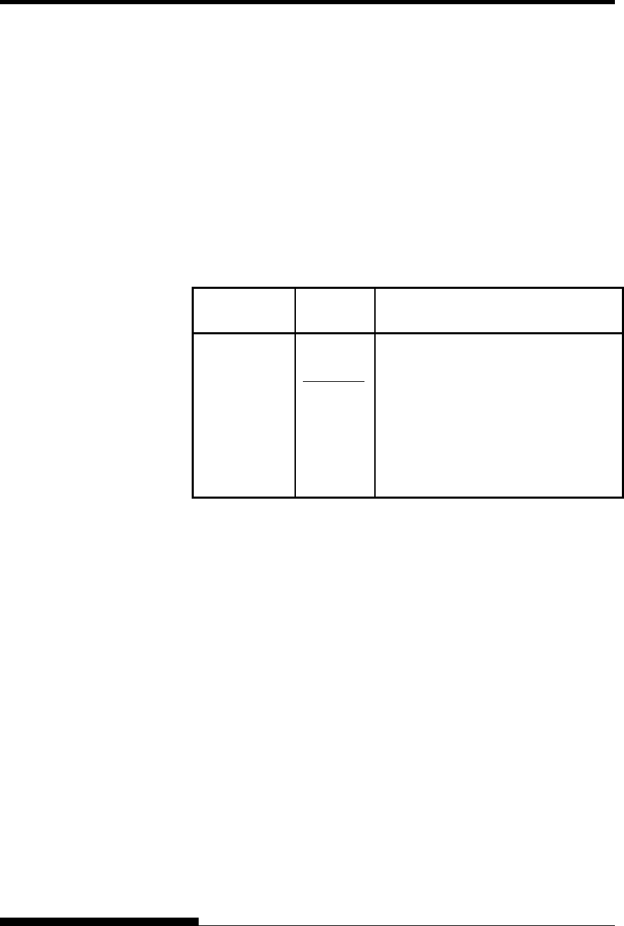
USING SETUP MODE
User's Manual 5-39
• Tear off for continuous forms
• Auto loading of single sheets
• Direct decoding of certain commands
• Enabling of the AREA OVER indicator
Table 5.6 describes the CONFIG items and options. Items are listed in
the order they are printed. The procedure for changing the configuration
options is described after Table 5.7.
Table 5.7 CONFIG Items and Options
NOTE: Underlined options are the factory defaults.
CONFIG
Items Options Description
<TEAROFF> Auto or manual tearoff feed.
MANUAL Automatic tearoff feed is invalid, and
tearoff feed must be done using the
TEAR OFF button.
AUTO
Automatic tearoff feed is valid but only
for continuous forms. Tearoff feed can
also be done using the TEAR OFF
button.
CHANGING
CONFIGURATION
OPTIONS
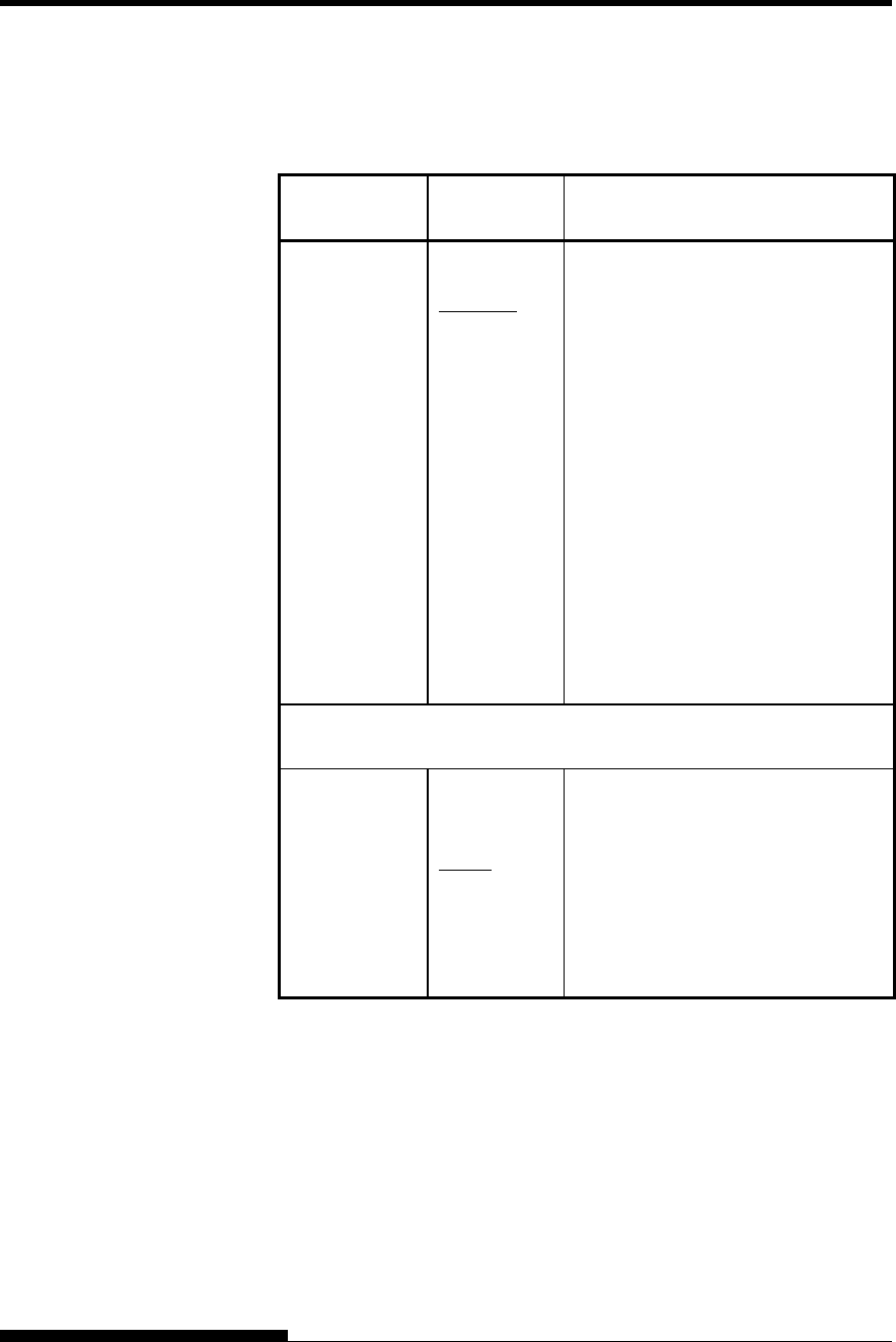
USING SETUP MODE
5-40 User's Manual
Table 5.7 CONFIG Items and Options (Cont.)
NOTE: Underlined options are the factory defaults.
CONFIG
Items Options Description
<TEARPOS> Tearoff position.
VISIBLE Select this option when your software
positions forms to the next top-
ofform after printing the last data.
The printer performs tearoff feed
without adding a form feed when data
transfer has stopped.
ALWAYS
Select this option when your software
stops after printing the last data. The
printer performs tearoff feed after
adding a form feed when data transfer
has stopped.
Note: For both settings, tearoff
positioning will fail if the page
length setting does not match the
actual perforation spacing.
The following <TEAR-EN> item is printed when TEAROFF:AUTO is
specified for the <TEAROFF> item.
<TEAR-EN> Tearoff enabled time (offset time).
0 SEC
1 SEC
2 SEC
4 SEC
6 SEC
The offset time is from when data
transfer stops to when the printer
performs automatic tearoff feed.
If the printer receives data again
within the offset time, the printer
does not perform automatic tearoff
feed.
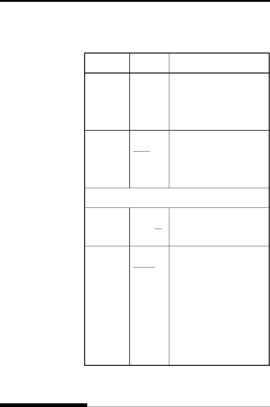
USING SETUP MODE
User's Manual 5-41
Table 5.7 CONFIG Items and Options (Cont.)
NOTE: Underlined options are the factory defaults.
CONFIG
Items Options Description
<TEAR-EN>
(continued)
In some application
programs, data
transfer may stop temporarily due to
internal processing. This setting can
avoid an undesired tearoff feed by
waiting for up to six seconds each
time data transfer stops.
<CUTLOAD> Single sheet autoloading.
AUTO Single sheet paper is automatically
loaded a certain time after you set the
paper.
BUTTON
Single sheet paper can be loaded by
pressing the LOAD button.
The following <LOADTIM> item is printed when CUTLOAD:AUTO
is specified for the <CUTLOAD> item.
<LOADTIM> Autoload start time.
0.5, 1.0, 1.5,
2.0 2.5,
3.0SEC
Autoloading starts when this amount
of time passes after you set single
sheet paper.
<DECODE> Command decode timing.
DIRECT The printer decodes certain
commands immediately after
receiving data.
Example:
ESC SUB I, ESC CR
P (DPL24C+) ESC
Q # (IBM XL24E)
QUEUED
The printer decodes commands after
storing all data (including commands)
in the input buffer. This speeds data
reception because the printer does not
require decoding time during data
reception.
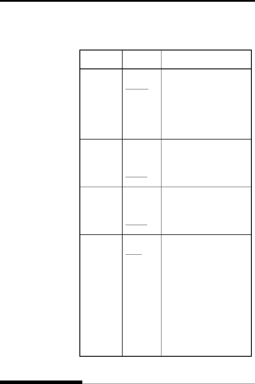
USING SETUP MODE
5-42 User's Manual
Table 5.7 CONFIG Items and Options (Cont.)
NOTE: Underlined options are the factory defaults.
CONFIG
Items Options Description
<AREACNT> Area-over detection control.
ENABLE Detects the left and right edges of
paper when loading the paper.
The printer does not print data
beyond the edges.
DISABLE
Does not detect the edges. Select
this option when you are using
colored or preprinted paper.
<CUT-ONL> Printer status after loading paper in
offline mode for single sheets.
OFFLINE Remains offline after paper loading.
ONLINE Goes into online after paper
loading.
<CNT-ONL> Printer status after loading paper in
offline mode for continuous forms.
OFFLINE Remains offline after paper loading.
ONLINE Goes into online after paper
loading.
<LOCK> Lock function of setup mode.
NONE Enables all buttons on the control
panel.
SETUP
Disables the setup-related buttons
to keep the printer from entering
setup mode during the offline state.
ALL
Disables the setup-related buttons
and the MENU button.
Once this setting has been selected,
setup mode cannot be entered from
the control panel. To cancel this
setting, turn the power on while
simultaneously pressing the HI
IMPACT, PAPER PATH, and
LF/FF buttons.
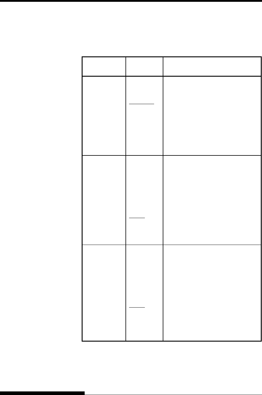
USING SETUP MODE
User's Manual 5-43
Table 5.7 CONFIG Items and Options (Cont.)
NOTE: Underlined options are the factory defaults.
CONFIG
Items Options Description
<//S//> Effectiveness of the Cut Sheet
Selection command (//S//).
DISABLE Makes the command ineffective.
ENABLE Makes the command effective.
Note: The Cut Sheet Selection
command (//S//) changes the
paper source to the paper table
and waits for manual insertion
of a cut sheet.
<FCNT-PE> Detection of end of front continuous
forms.
TRACTOR
Paper end is detected by the sensor on
the tractor unit.
Paper-end unprinted area:
Continuous forms: About 101 mm
EDGE Regardless of paper end, printing
continues near to the edge of paper.
Paper-end unprinted area: About 4
mm for both continuous forms
<RCNT-PE> Detection of end of rear continuous
forms.
TRACTOR
Paper end is detected by the sensor on
the tractor unit.
Paper-end unprinted area:
Continuous forms: About 157 mm
EDGE Regardless of paper end, printing
continues near to the edge of paper.
Paper-end unprinted area:
About 4 mm for both continuous
forms
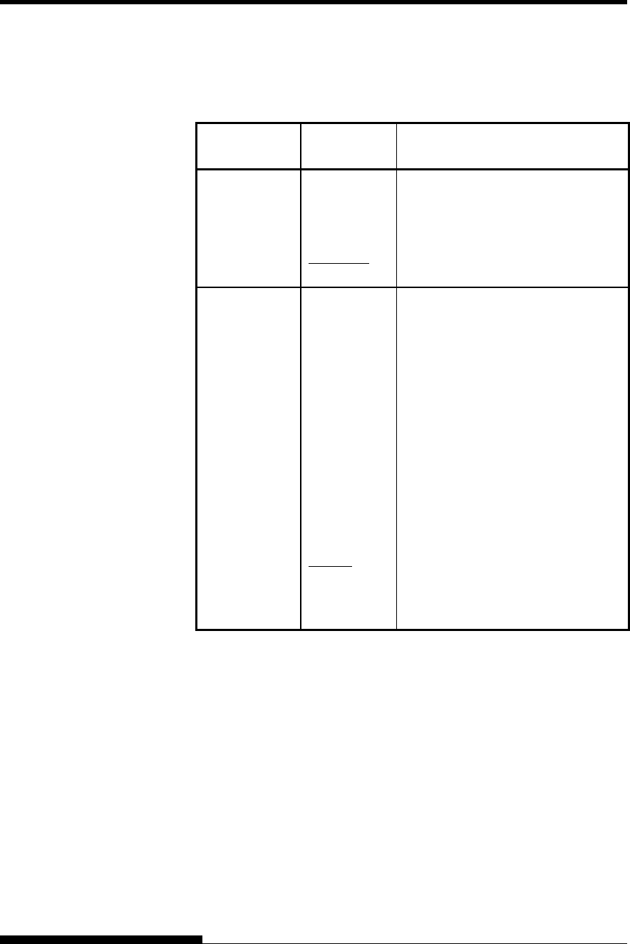
USING SETUP MODE
5-44 User's Manual
Table 5.7 CONFIG Items and Options (Cont.)
NOTE: Underlined options are the factory defaults.
CONFIG
Items Options Description
GATHER Setting of ribbon protective control at
a line feed on continuous forms
ENABLE The protective control is executed.
DISABLE The protective control is not
executed.
CUT-CTL Setting of retracting control at
canceling TEAR OFF of continuous
forms.
PRCISIN
The precision-prioritized retracting
control is executed.
It retracts a certain amount of paper
(the top part of the paper which hangs
out from the TOFS), and then moves
back to the position before TEAR
OFF. If TOFS detects paper end
when a certain amount of paper is
retracted, it executes the continuous
forms save operation and then
executes the paper loading operation.
SPEED The speed-prioritized retracting
control is executed.
It retracts the paper by the amount the
paper was advanced.
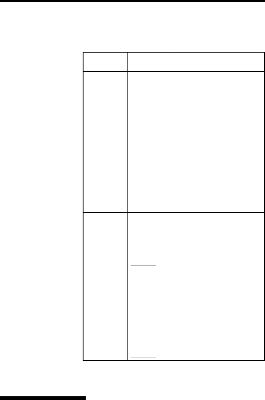
USING SETUP MODE
User's Manual 5-45
Table 5.7 CONFIG Items and Options (Cont.)
NOTE: Underlined options are the factory defaults.
CONFIG
Items Options Description
SKIP-PR Setting of printing speed change
processing (skip)
ENABLE The skip processing is executed.
When a certain amount of blank
spaces are found in a line, it
changes the printing speed for the
blank spaces.
DISABLE The skip processing is not executed.
It does not change the printing
speed for the blank spaces.
- If the printing speed of the
printing data varies before and
after the blank spaces (such as
LQ characters + blank space +
CQ characters), it changes
printing speeds regardless of
this setting.
STATUS Setting of the asynchronous status
function
ENABLE
The status information is stored in
the send buffer by a nibble mode
request.
DISABLE The status information is not stored
in the send buffer by a nibble mode
request.
BANDCTL Setting of reducing backward line
feeds as much as possible.
Backward line feeds occur when
printing vertical enlargement
characters or multi-path characters
which involve several printing
paths for a print activation.
ENABLE Reduce control is performed.
DISABLE Reduce control is not performed.
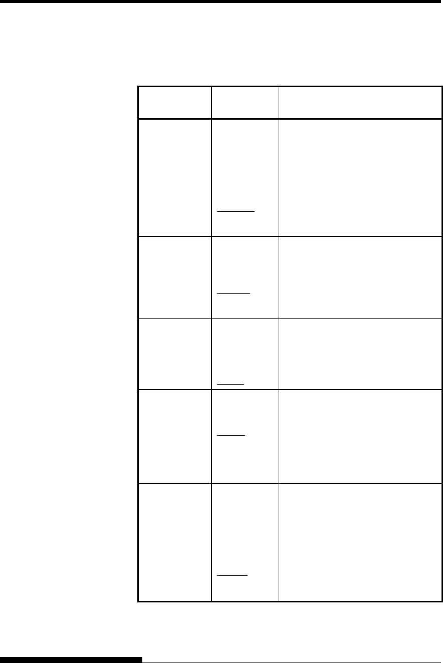
USING SETUP MODE
5-46 User's Manual
Table 5.7 CONFIG Items and Options (Cont.)
NOTE: Underlined options are the factory defaults.
CONFIG
Items Options Description
TOF-CTL Setting of priority on TOF control to
a printer driver specification or a
setup specification. TOF control
determines the amout of the top
margin when paper is fed to the home
position.
DRIVER Driver specification is given priority.
SETUP Setup specification is given priority.
<CUTEDIR> Selection of the eject direction of cut
sheets with manually feeding of cut
sheets
FRONT Ejected to the front.
REAR Ejected to the rear.
<CSFEDIR> Selection of the eject direction of cut
sheets with use of a CSF
FRONT Ejected to the front.
REAR Ejected to the rear.
<CUTEJCT> Selection for automatic ejection of
cut sheets
AUTO Automatic ejection of cut sheets
when no cut sheet is detected
MANUAL
No automatic ejection of cut sheets
when no cut sheet is detected
<FL-CENT> Selection of the print carrier position
when paper is fed via a front path
(with feeding of continuous forms
paper from the front, use of a front
CSF, and manual feeding of cut
sheets)
POSN1 Position 1: Column 31
POSN2 Position 2: Column 42
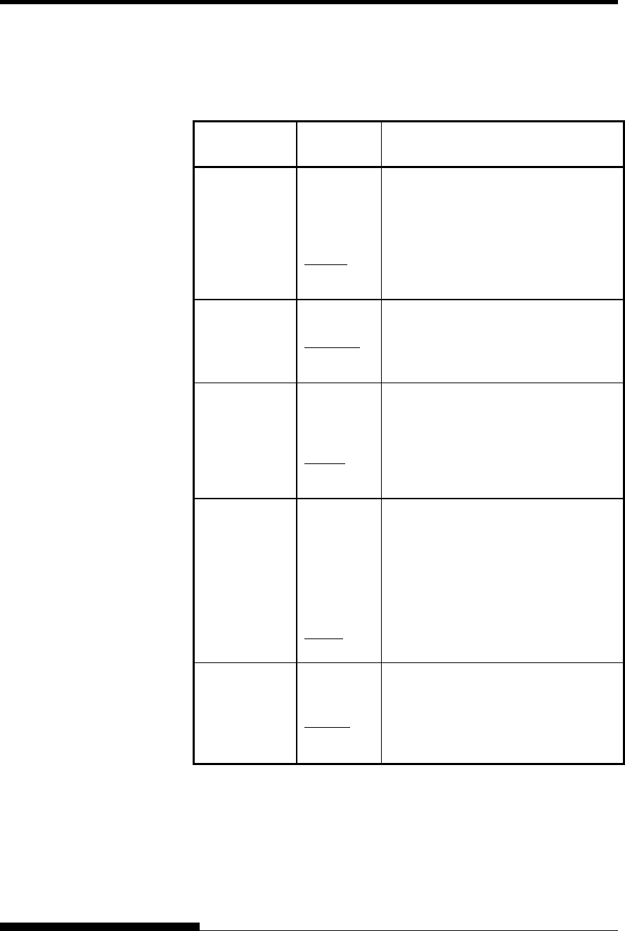
USING SETUP MODE
User's Manual 5-47
Table 5.7 CONFIG Items and Options (Cont.)
NOTE: Underlined options are the factory defaults.
CONFIG
Items Options Description
<RL-CENT> Selection of the print carrier position
when paper is fed via a front path (with
feeding of continuous forms paper from
the rear and use of a rear CSF)
POSN1 Position 1: Column 31
POSN2 Position 2: Column 42
<SKEWCNT> Detection of paper feed skew
ENABLE Enables paper feed skew detection.
DISABLE Disables paper feed skew detection.
<FF-CODE> Selection of the method of processing
for the FF code is received in cut sheet
mode or for the “LF/FF” switch
EJECT Ejects cut sheets.
FORM-FD Uses a page break.
<PRT-CUT> Selection of the cut amount (margin) on
both sides of continuous forms paper
when AREACNT, the cut amount in
continuous printing, is set to ENABLE
71/180
Sets the cut amount for printing to
71/180 inches (about 10.0 mm).
99/180 Sets the cut amount for printing to
99/180 inches (about 14.0 mm).
<CSFBIN1> Selection of the CSF for bin 1 if both a
front CSF and rear CSF are mounted
FRONT Front CSF
REAR Rear CSF
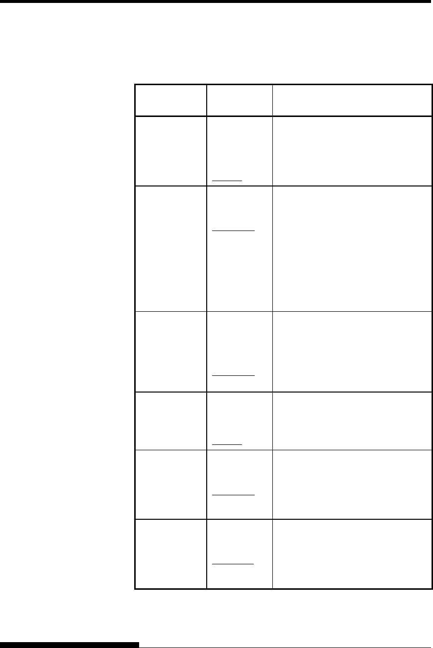
USING SETUP MODE
5-48 User's Manual
Table 5.7 CONFIG Items and Options (Cont.)
NOTE: Underlined options are the factory defaults.
CONFIG
Items Options Description
<CNT-LD> Selection for the paper feeding of
continuous forms paper
PRCISIN Gives a higher priority to precision.
SPEED Gives a higher priority to speed.
<CSF-LD> Selection of the method of feeding
from the CSF
NORMAL Feeds paper directly from the CSF
hopper.
SWBACK
Feeds paper from the CSF hopper to
either the cut sheet table used with a
front CSF or the stacker used with a
rear CSF. Then, that paper is fed
again.
<CSFAPTC> Paper thickness detection with use of
a CSF
ALWAYS Every sheet of paper that is fed
NORMAL Sheet of paper that is fed immediately
after the feed pin is switched
<LF-CTL> Selection for LF mode
PRCISIN Gives a higher priority to precision.
SPEED Gives a higher priority to speed.
<PR-MODE> Selection for print mode
(standard/low noise)
NORMAL Prints in standard mode.
QUIET Prints in low-noise mode.
<HI-IMPT> Selection for high printing pressure
mode
DISABLE Prints in standard pressure mode.
ENABLE Prints in high printing pressure mode.