Fujitsu Isotec 018M33325A Dot Matrix Printer User Manual 2 of 2
Fujitsu Isotec Limited Dot Matrix Printer 2 of 2
Contents
- 1. User manual 1 of 2
- 2. User manual 2 of 2
User manual 2 of 2
USING SETUP MODE
User's Manual 5-49
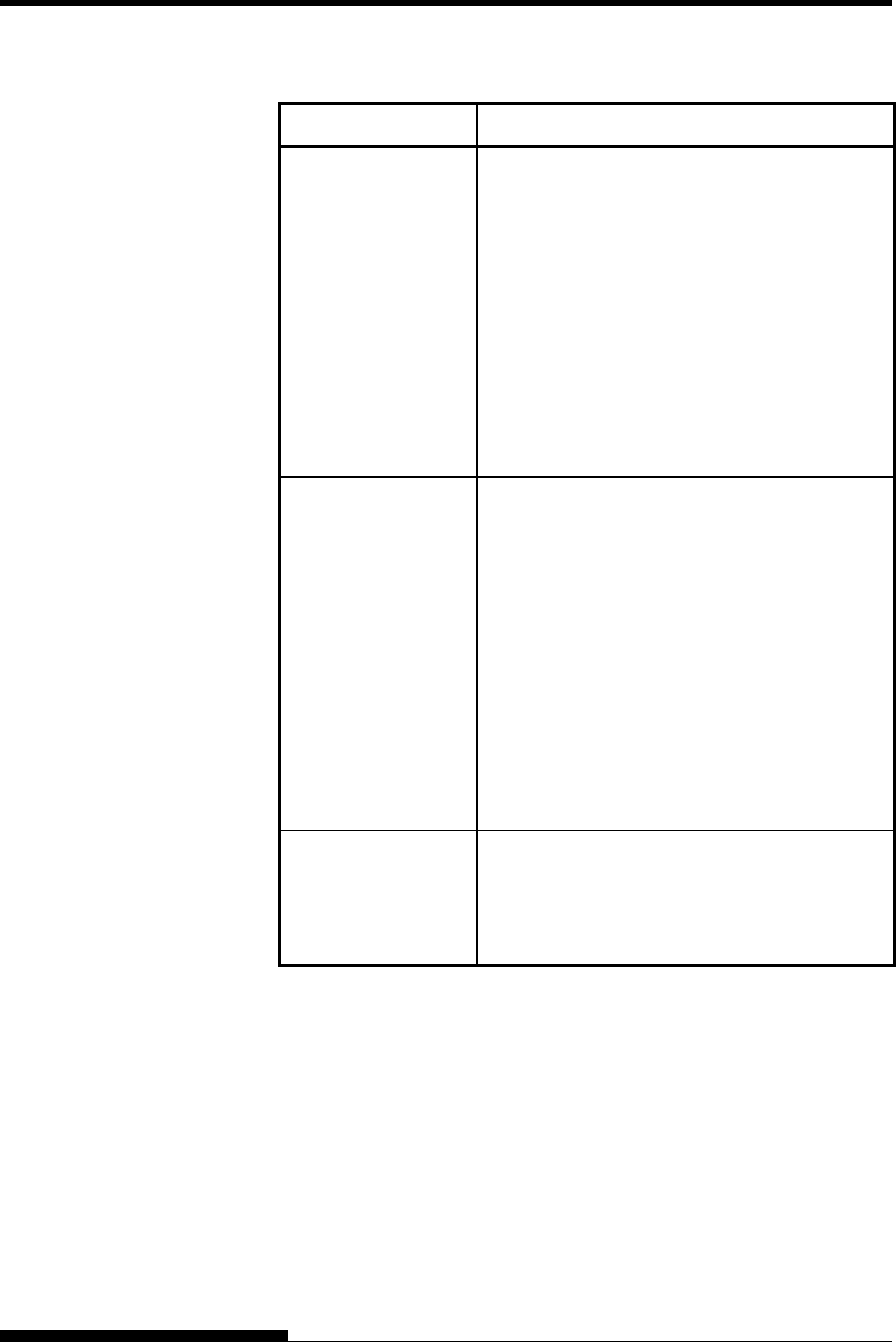
Table 5.7 CONFIG Items and Options (Cont.)
NOTE: Underlined options are the factory defaults.
CONFIG
Items Options Description
<DQ-MODE > Selection for draft quality printing
mode
MODE1 Prints in 720CPS printing mode.
MODE2 Prints in 540CPS printing mode.
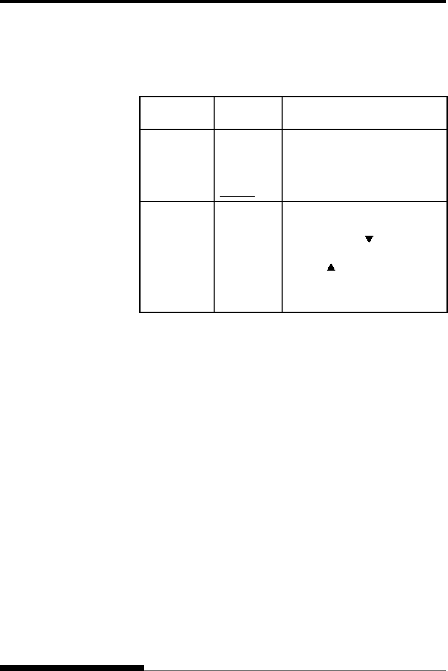
<==END==> (LED only)
Indicates the end of the CONFIG
item list. Press the button to print
the first item, which is <TEAROFF>.
Press the button to print the
previous item. Press the ONLINE
button to reprint the
<<FUNCTION>> menu.
USING SETUP MODE
5-50 User's Manual
The GAP-ADJ function adjusts the gap between the print head and
the paper. The automatic paper thickness control (APTC) feature is
built in this printer. If you adjust the gap manually or fix the gap,
change the option of GAP-ADJ function.
For the procedure how to change the options refer to the section
Setup Mode Example earlier in this chapter.
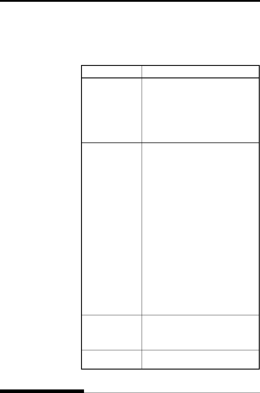
Table 5.8 GAP-ADJ Items and Options
NOTE: Underlined options are the factory defaults.
GAP-ADJ
Items Options Description
<AMOUNT> Specifies the print head gap.
AUTO The print head gap is set
automatically.
MANUAL
Turn the paper thickness dial
(indicator) manually.
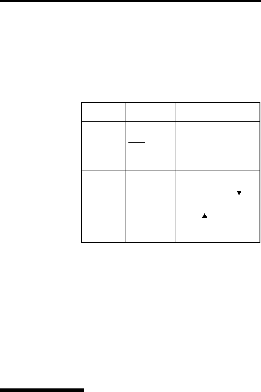
<==END==> (LED only)
Indicates the end of the GAP-
ADJ item list. Press the
button to print the first item,
which is <AMOUNT>.
Press the button to print the
previous item. Press the
ONLINE button to reprint the
<<FUNCTION>> menu.
HEAD GAP
ADJUSTMENT
ITEMS AND
OPTIONS

USING SETUP MODE
User's Manual 5-51
This section describes how to exit setup mode and save any changes you
made:
To exit setup mode immediately, select the SAVE & END (for LED
type) SAVE&EXIT (for LCD type) function.
Any settings changed while in setup mode are saved as the new power-
on defaults for the printer. The new defaults remain active until you
change them again.
NOTE (LED only)
The only way to exit setup mode without saving your changes is to
turn off the printer. When you turn the printer back on, the previous
default settings are used.
Procedure (for LED type)
To exit setup mode and save your changes using SAVE/END, proceed as
follows:
1. Print the <<FUNCTION>> menu.
The <<FUNCTION>> menu should be the last printed line on
the page. If the menu is not printed, press the ONLINE button to
print the menu. The <<FUNCTION>> menu is shown below:
<< FUNCTION >>
SAVE&END MENU1 MENU2 HARDWRE ADJUST CONFIG GAP-ADJ DEFAULT LIST SELF-
T
ST
HEX-DUMP V-ALMNT INITIAL
2. Select the SAVE/END function.
Make sure that the cursor on the left edge of the aluminum print
guide is positioned under SAVE & END. Press the button or
the button to select SAVE & END. The printer exits setup
mode and returns online (the ONLINE indicator lights green).
Any changes you made while in setup mode are saved.
Procedure (for LCD type)
To exit setup mode and save or cancel your changes using SAVE/EXIT
function, proceed as follows:
1. Push SAVE/EXIT button.
Push SAVE/EXIT button, then “ :SAVE :CANCEL” is
displayed on LCD PANEL
2. Push or button.
Push to save changing.
Push to cancel changing.
EXITING AND
SAVING

USING SETUP MODE
5-52 User's Manual
This section describes how to reset the printer’s power-on defaults,
all of the factory defaults, or the factory defaults only for MENU1
and MENU2.
Resetting Power-On Defaults
Power-on defaults are the settings saved in the printer’s permanent
memory. The defaults are enabled whenever you turn the printer on.
The only (LED type) way to reset the power-on defaults is to turn the
printer off and then on again. This method is useful if you have made
changes in setup mode that you do not want to save. LCD type, save or
cancel options are available on exit menu.
Resetting Factory Defaults
Factory defaults are those settings preselected at the factory. For a list of
the printer’s factory defaults, see the section Printing a List of Selected
Options earlier in this chapter. To reset the factory defaults for all
functions, proceed as follows:
1. Turn off the printer.
2. While pressing the LOAD and, TEAR OFF buttons, turn on the
printer. Continue to press the two buttons until the printer beeps.
The factory defaults are now reset.
Another available method is to select INITIAL in SETUP mode.
The method of making settings is the same as the method for
selecting DEFAULT on the next page, except that INITIAL
must be selected instead of DEFAULT.
Resetting Factory Defaults in MENU1 and
MENU2
This method resets factory defaults for MENU1 and MENU2 options,
listed in Table 5.4, but does not reset the printer hardware, print position
adjustment, and configuration options. To reset the factory defaults in
MENU1 and MENU2, select DEFAULT in SETUP mode. Detail of
method as follows:
RESETTING
DEFAULTS

USING SETUP MODE
User's Manual 5-53
1. Enter setup mode (LED type).
Press the AUTO GAP button and the HI IMPACT button
simultaneously until the printer beeps. Wait for the printer to
stop printing and check that the following <<FUNCTION>>
menu is printed:
<< FUNCTION >>
SAVE&END MENU1 MENU2 HARDWRE ADJUST CONFIG GAP-ADJ DEFAULT LIST SELF-
T
ST
HEX-DUMP V-ALMNT INITIAL
2. Select the DEFAULT function (LED type).
Repeatedly press the “TEAR OFF” or “LOAD” button to
position the cursor on the left edge of the aluminum print guide
on DEFAULT. Press the button or the button to select the
DEFAULT function. The printer reprints the <<FUNCTION>>
menu. The default values in MENU1 and MENU2 are now reset
(not saved yet).
3. Save reset values (LED type).
To exit setup mode and save the new defaults, make sure that
the cursor on the left edge of the aluminum print guide are
positioned on SAVE & END, then press the MICRO button
or the MICRO button.
1. Enter setup mode (LCD type).
Press the SETUP button at offline state. Check that the “SETUP
MODE” is displayed on LCD panel.
2. Select the DEFAULT function (LCD type).
Repeatedly press the “ ” or “ ” button to display “SUB
FUNCTION”. And then press the“ ” button to move lower layer.
And then repeatedly press the “ ” or “ ” button to display
“DEFAULT”. And then press the “SELECT” button to reset the
default values in MENU1 and MENU2 (not saved yet).
3. Save reset values (LED type).
Exit setup mode, saving the factory defaults.
Push SAVE/EXIT button. Check that “ :SAVE :CANCEL” is
displayed on LCD panel. Then press the“ ” button.

USING SETUP MODE
5-54 User's Manual
This section describes how to use the following diagnostic functions:
• SELF-TST
• HEX-DUMP
• V-ALMNT
These functions are used for checking print quality and diagnosing
printer problems. HEX-DUMP also provides useful information for
programmers.
Printing the Self-Test
The SELF-TST function prints test pages to check how the printer
operates independently of your computer. The self-test does not check
the interface between the computer and the printer.
The self-test prints the printer’s firmware version, its resident emulations,
and all of the characters available in the currently selected character set.
If the DPL24C PLUS emulation is selected for MENU1, the self-test is
printed using the settings currently assigned to MENU1.
Procedure
This procedure assumes that you are in setup mode. To print the selftest,
make sure that continuous forms paper is loaded into the printer.
Then proceed as follows :
1. Print the <<FUNCTION>> menu.(LED)
The <<FUNCTION>> menu should be the last printed line on
the page. If the menu is not printed, press the ONLINE button to
print the menu. If you are using the HEX-DUMP function,
press the “TEAR OFF” or “LOAD” button instead of the
ONLINE button to print the menu. The following
<<FUNCTION>> menu is printed:
<< FUNCTION >>
SAVE&END MENU1 MENU2 HARDWRE ADJUST CONFIG GAP-ADJ DEFAULT LIST SELF-TST
HEX-DUMP V-ALMNT INITIAL
2. Select the SELF-TST function.(LED)
Repeatedly press the “TEAR OFF” or “LOAD” button to
position the cursor on the left edge of the aluminum print guide
on SELF-TST, and then press the “ ” button or the “ ” button.
The printer selects SELF-TST and starts printing. A short help
menu is printed at the top of the page, followed by the selftest.
Note that the printer is not online during self-test printing.
USING THE
DIAGNOSTIC
FUNCTIONS

USING SETUP MODE
User's Manual 5-55
1. Move to TOP MENU of SETUP MODE.(LCD)
Press the “ ” button until “SETUPMODE” is displayed on LCD
panel.
2. Select the SELF-TST function.(LCD)
Repeatedly press the “ ” or “ ” button to display
“SELFDIAGNOSTIC”. And then press the“ ” button to move
lower layer. And then repeatedly press the “ ” or “ ” button
to display “SELF-TEST”. And then press the “SELECT” button
to start self-test printing. A short help menu is printed at the top
of the page, followed by the selftest. Note that the printer is not
online during self-test printing.
3. Examine the self-test page.
A sample self-test page is shown in Chapter 2. To pause during
self-test printing, press the “LOAD” button. To resume self-test
printing, press the “LOAD” button again.
4. Exit the SELF-TST function.
Exit the SELF-TST function in either of the following ways:
• To exit SELF-TST and remain in setup mode, press the
LF/FF button. The <<FUNCTION>> menu is then
reprinted (LED type).
• To exit SELF-TST and return online, press the ONLINE
button. The printer permanently saves any changes made
while in setup mode and returns online.
The self-test can also be started by turning off the printer, and then
pressing the LF/FF button while turning the printer back on. As
described in Chapter 2, this method is useful when you first set up the
printer.

USING SETUP MODE
5-56 User's Manual
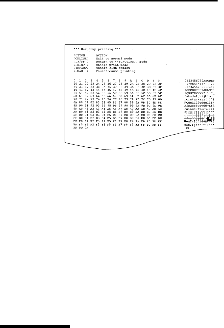
Printing Hex Dumps
The HEX-DUMP function prints data and commands in hexadecimal
characters and abbreviated control codes. The IBM character set 2 is
used for printing (see Appendix E). The HEX-DUMP function is useful
for checking whether your computer is sending the correct commands to
the printer and whether the printer is executing the commands correctly.
It is also useful for debugging software programs.
Procedure
To print hex dumps, make sure that continuous forms paper is loaded
into the printer. Then proceed as follows:
1. Enter setup mode(LED).
Press the AUTO GAP button and the HI IMPACT button
simultaneously until the printer beeps. Wait for the printer to
stop printing and check that the following <<FUNCTION>>
menu is printed:
2. Select the HEX-DUMP function(LED).
<< FUNCTION >>
SAVE&END MENU1 MENU2 HARDWRE ADJUST CONFIG GAP-ADJ DEFAULT LIST SELF-TST
HEX-DUMP V-ALMNT INITIAL
Repeatedly press the “TEAR OFF” or “LOAD” button to
position the cursor on the left edge of the aluminum print guide
on HEX-DUMP, then press the S button or the T button to
select the HEX-DUMP function. The printer goes online and
prints a header and a short help menu.
1. Enter setup mode(LCD).
Press the SETUP button at offline state. Check that the “SETUP
MODE” is displayed on LCD panel.
2. Select the HEX-DUMP function(LCD).
Repeatedly press the “ ” or “ ” button to display
“SELFDIAGNOSTIC”. And then press the“ ” button to move
lower layer. And then repeatedly press the “ ” or “ ” button
to display “HEX-DUMP”. And then press the “SELECT” button.
The printer goes online and prints a header and a short help
menu.
3. Print the hex dump.
To start hex dump printing, send your file or program to the
printer. The printer goes online and prints the hex dump.
Press the LOAD button to pause during hex dump printing. To
resume hex dump printing, press the “LOAD” button again.
USING SETUP MODE
User's Manual 5-57
NOTE
When hex dump printing stops, data that is less than one
line printed yet, to print remaining data exit Hex-Dump
mode(push LF/FF or ONLINE).
Sample hex dump
4. Exit the HEX-DUMP function.
Exit the HEX-DUMP function in either of the following ways:
• To remain in setup mode, press the LF/FF button. The
<<FUNCTION>> menu is then reprinted (LED type). For
details on other functions, see other sections in this chapter.
• To return to online normal mode, press the ONLINE button.
If you press the ONLINE button while the hex dump is
printing, the printer immediately switches to normal online
mode, but data that was sent to the printer is printed in
normal mode. At same time the printer permanently saves
any changes made while in setup mode.
You can also enter hex dump mode, by turning off the printer, and then
turning the printer back on while simultaneously pressing the ONLINE
button and the LF/FF button until the printer beeps.

USING SETUP MODE
5-58 User's Manual
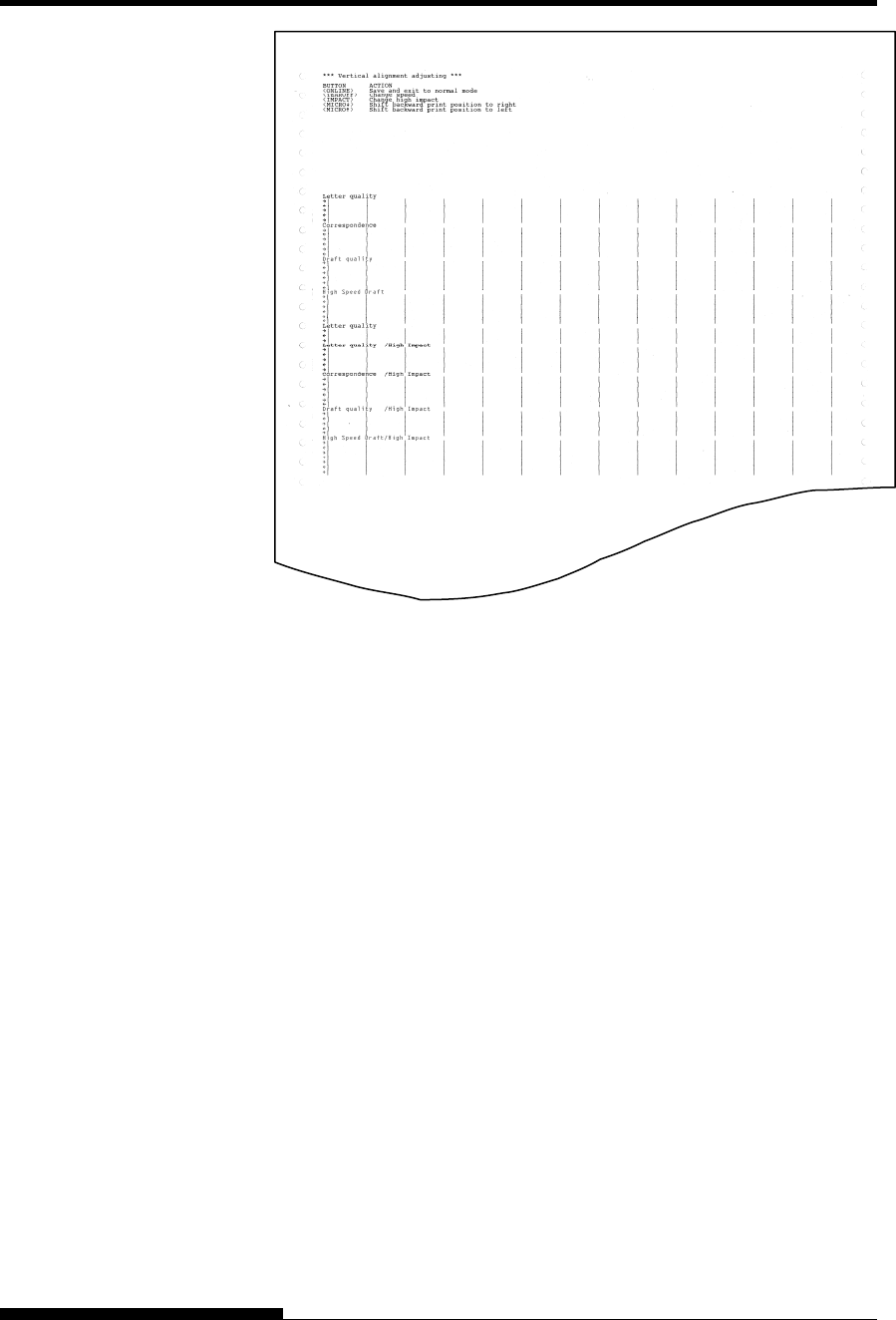
Checking Vertical Print Alignment (V-ALMNT)
The V-ALMNT function corrects the vertical character displacement that
sometimes occurs with bidirectional printing. Characters printed from
left to right are not aligned with characters printed from right to left as
shown below:
This example shows how printing looks
when characters are vertically
misaligned. Note that the left
margin is not straight.
If you notice misaligned printing, use the following procedure to check
and correct the vertical print alignment.
Procedure
Make sure that continuous forms paper is loaded in the printer. If
possible, use forms at least 356 mm (14 inches) wide to avoid printing on
the platen. However, you can also use letter or A4 size forms if you set
the WIDTH option in MENU1 to 8 inches. See the section Changing
MENU1 and MENU2 Items and Options for details. Then proceed as
follows to check and correct vertical print alignment:
1. Enter setup mode (LED).
Press the AUTO GAP button and the HI IMPACT button
simultaneously until the printer beeps. Wait for the printer to
stop printing and check that the following <<FUNCTION>>
menu is printed:
<< FUNCTION >>
SAVE&END MENU1 MENU2 HARDWRE ADJUST CONFIG GAP-ADJ DEFAULT LIST SELF-TST
HEX-DUMP V-ALMNT INITIAL
2. Select the V-ALMNT function(LED).
Repeatedly press the “TEAR OFF” or “LOAD” button to
position the cursor at V-ALMNT, then press the “ ” button or
the “ ” button to select the V-ALMNT function. The printer
prints the help menu then starts printing rows of parallel bars
using letter quality speed.
1. Enter setup mode(LCD).
Press the SETUP button at offline state. Check that the “SETUP
MODE” is displayed on LCD panel.
2. Select the V-ALNMNT function(LCD).
Repeatedly press the “ ” or “ ” button to display
“SELFDIAGNOSTIC”. And then press the“ ” button to move
lower layer. And then repeatedly press the “ ” or “ ” button
to display “V-ALNMNT”. And then press the “SELECT” button.
The printer prints the help menu then starts printing rows of
parallel bars using letter quality speed.
USING SETUP MODE
User's Manual 5-59
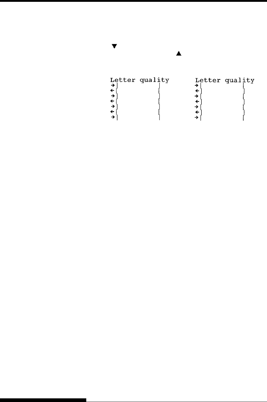
3. Adjust the vertical print alignment at letter quality speed.
Examine the parallel bars. If the bars are aligned (not jagged),
go to step 4. If the bars are offset to the left, repeatedly press the
“” button until the bars are aligned. If the bars are offset to the
right, repeatedly press the “ ” button until the bars are aligned.
(In the following figure, the first line is assumed to be printed
from left to right.)
Bars offset to the left Bars offset to the right
4. Adjust the vertical print alignment at correspondence speed.
Press the “TEAR OFF” button to switch from letter speed to
correspondence speed.
Examine the parallel bars and adjust the vertical print alignment
as described in step 3.
Press the HI IMPACT button to enter Hi Impact mode. Make
similar adjustments.
5. Adjust the vertical print alignment at draft speed.
Press the “TEAR OFF” button to switch from correspondence
speed to draft speed.
Examine the parallel bars and adjust the vertical print alignment
as described in step 3.
Press the HI IMPACT button to enter Hi Impact mode. Make
similar adjustments.
6. Adjust the vertical print alignment at high draft speed.
Press the “TEAR OFF” button to switch from draft speed to
high draft speed.
Examine the parallel bars and adjust the vertical print alignment
as described in step 3.
Press the HI IMPACT button to enter Hi Impact mode. Make
similar adjustments.
7. Exit the V-ALMNT function.
Press the ONLINE button to exit the V-ALMNT function and
save the new vertical alignment settings. The printer exits setup
mode and returns online.
NOTE
To exit the V-ALMNT function, you must exit setup mode.
USING SETUP MODE
5-60 User's Manual
Correct vertical print alignment
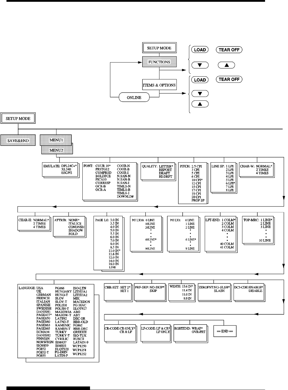
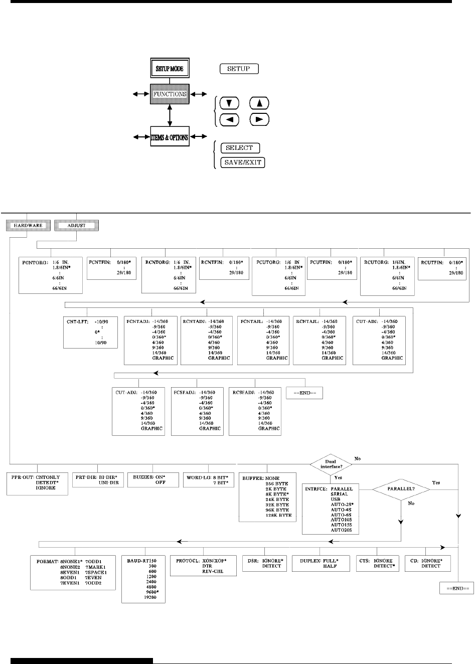
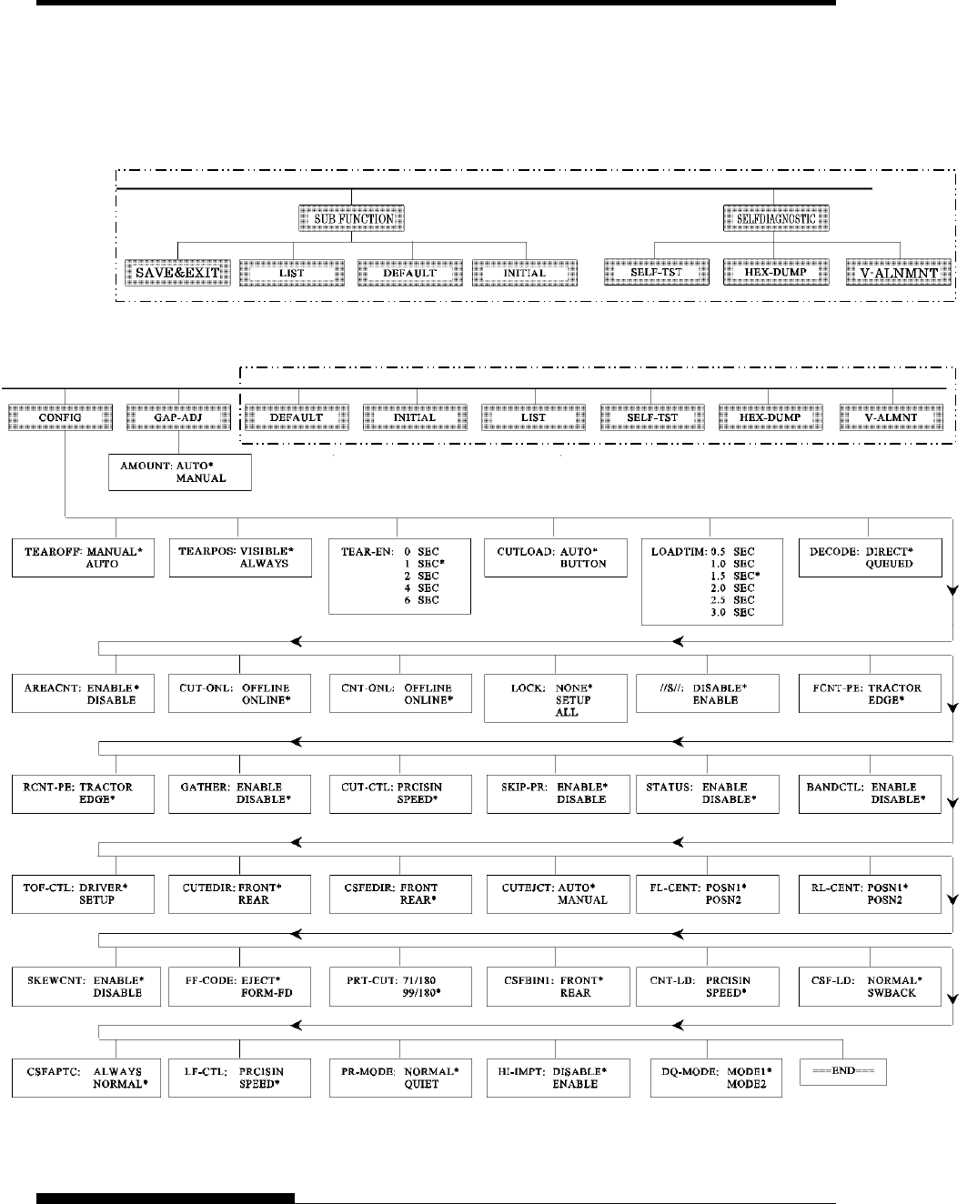
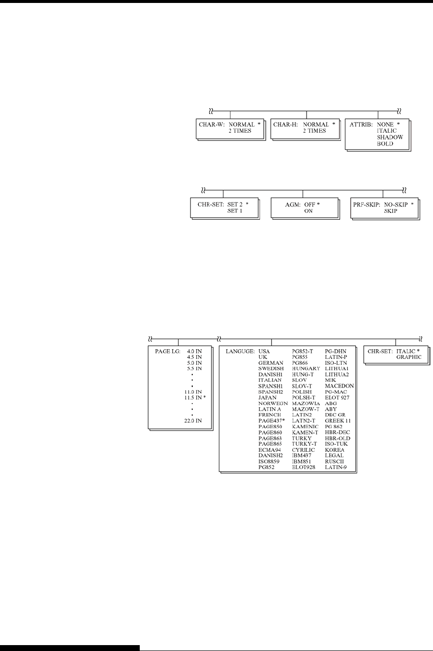
The following flowchart shows how setup mode is organized for the
Fujitsu DPL24C PLUS emulation. Differences in the IBM Proprinter
XL24E and Epson ESC/P2 emulations are summarized after the
flowchart.
SETUP MODE
REFERENCE
USING SETUP MODE
User's Manual 5-61
DPL24C PLUS ORGANIZATION
N
ote:
Asterisks (*) indicate default setting at shipment. or
or
or
Move the cursor on the prime guide.
Select function.
Select option, print next item.
Select option, print previous item.
Move the cursor on the prime guide.
General operation for LED control panel.
USING SETUP MODE
5-62 User's Manual
General operation for LCD control panel.
To enter SETUP MODE press SETUP at offline state.
Move displaced items
Select the displayed option.
Exit SETUP MODE.
USING SETUP MODE
User's Manual 5-63
This area is only for LED type.
This area is only for LCD type instead of below area.
USING SETUP MODE
5-64 User's Manual
Differences in IBM Proprinter XL24E Emulation
In the IBM Proprinter XL24E emulation, MENU1 and MENU2 differ
from the DPL24C PLUS emulation in the following ways:
• The following options are different:
• The AGM item is provided:
Differences in Epson ESC/P2 Emulation
In the Epson ESC/P2 emulation, MENU1 and MENU2 differ from the
DPL24C PLUS emulation in the following ways:
• The ZEROFNT and LF-CODE items are not defined.
• The following options are different:

USING SETUP MODE
User's Manual 5-65
The preceding sections describe offline setup mode. This section
introduces online setup mode. The tedious task of setting up printer
features one-by-one from the control panel and printing and checking the
desired options on paper can be avoided by using online setup mode. In
online setup mode, printer features are set via the computer rather than
the printer control panel.
Put the printer in online setup mode, in either of the following two ways:
• Turn the printer off and then turn the printer back on while
pressing the TEAR OFF button. Hold down the button until the
printer beeps.
• Issue the printer command ESC e ONLINE. This command is
valid in any emulation.
Send setup data from the computer in any of the following three ways:
• Enter setup data directly from the computer keyboard before
starting your job. With MS-DOS, hold down the Ctrl key and
type P. Data entered from the keyboard is sent directly to the
printer. When data entry is complete, hold down the Ctrl key
again and type P. This method is useful when just a few settings
need to be changed.
• Use an editor program to prepare a setup data file and then send
the file to the printer using a command before starting your job.
With MS-DOS, use the COPY command. This method is useful
when settings are used repeatedly.
• Write a program that enables interactive entry of setup data on
the CRT screen. This method is the most useful of the three.
This printer is provided with a floppy disk which contains this
program called DLMENU. For DLMENU, see the last section
of chapter 2.
To exit from online setup mode, send EXIT as the last setup data.
For details of setup data and its format, refer to the programmer’s manual
for each emulation.
ONLINE SETUP
MODE

USING SETUP MODE
5-66 User's Manual

User's Manual 6-1
6
CHAPTER 6 MAINTENANCE
MAINTENANCE
Your printer requires very little care. Occasional
cleaning and replacement of the ribbon cartridge
are all that is required.
Lubrication of the printer is usually not necessary.
If the print head carriage does not move smoothly back and forth, clean
the printer as described in this chapter. If the problem continues, contact
your dealer to determine whether lubrication might be needed.
The front cover, the rear stacker, and the soundproof cover or the paper
table of the printer help protect against dust, dirt, and other contaminants.
However, paper produces small particles that accumulate inside the
printer.
This section explains how to clean and vacuum the printer and how to
clean the platen.
It is easier to clean the printer when the front cover and the rear stacker
are removed.
Cleaning and Vacuuming the Printer
WARNING
To avoid any possibility of injury, before cleaning the
printer, turn off the power to both the printer and the
computer, and unplug the printer.
Use the following procedure to clean and vacuum the printer as required:
1. Remove any paper from the printer. Make sure that the power is
off, and then disconnect the printer power cord.
2. Using a soft vacuum brush, vacuum the exterior of the printer.
Be sure to vacuum the air vents at the front, left sides, and
bottom of the printer. Also vacuum the paper table, rear stacker,
and the cut sheet feeder.
3. Use a soft, damp cloth to wipe the exterior of the printer,
including the cover, paper table, and rear stacker. A mild
detergent may be used.
CAUTION
Do not use solvents, kerosene, or abrasive cleaning materials
that may damage the printer.
CLEANING
MAINTENANCE
6-2 User's Manual
4. Open the front cover of the printer and remove the ribbon
cartridge. If necessary lay down control panel. Using a soft
vacuum brush, gently vacuum the platen, print head carriage,
and surrounding areas. You can easily slide the print head to the
left or right when the power is off. Be careful not to press too
hard on the flat ribbon cable that extends from the print head
carriage.
Printer interior
5. Re-install the ribbon cartridge. Close the front cover.
6. Raise the soundproof cover or paper table and rear stacker.
Vacuum the forms tractors and surrounding areas.
Cleaning the Platen
Clean the platen about once a month to remove excess ink. Use the
platen cleaner recommended by your supplier and proceed as follows:
1. Apply a small amount of platen cleaner to a soft cloth. Avoid
spilling platen cleaner inside the printer.
CAUTION
Do not use alcohol to clean the platen. Alcohol may cause the
rubber to harden.
2. Place the cloth against the platen.
3. To dry the platen, place a dry cloth against the platen.
MAINTENANCE
User's Manual 6-3
There are two ways of replacing the ribbon. You can install a new ribbon
cassette in the printer or refill the old ribbon cassette with new ribbon
from a ribbon sub cassette. Appendix A lists order numbers for ribbon
cassettes and ribbon sub cassettes. The following procedure is for ribbon
cassettes. For ribbon sub cassettes, refer to the instructions shipped with
the sub cassette.
To replace the ribbon cassette:
1. Turn off the printer.
Note:
If the power is turned off during or immediately after
printing, turn on the power again. Verify that the print
head has moved to the ribbon replacement position, and
then turn off the power again.
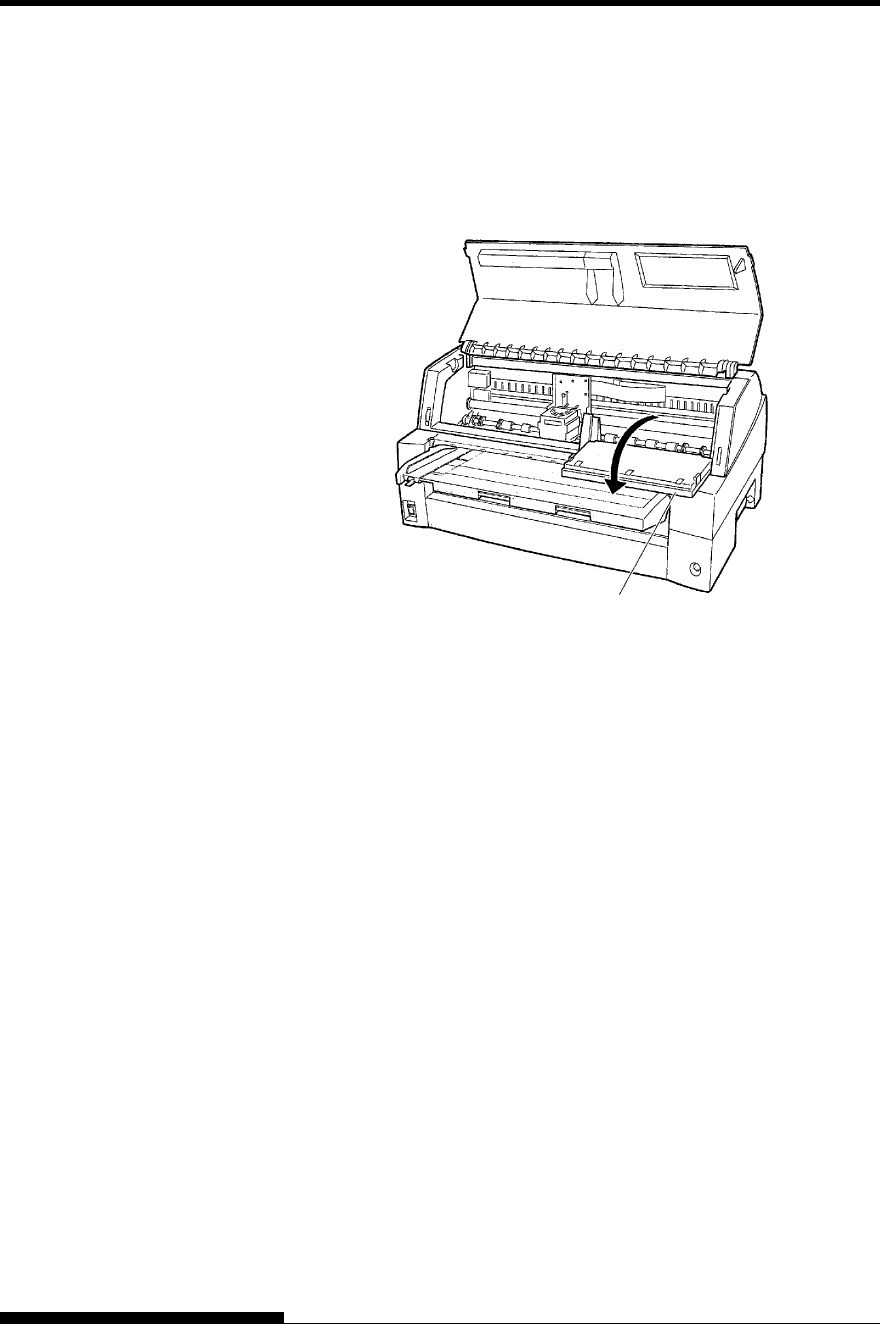
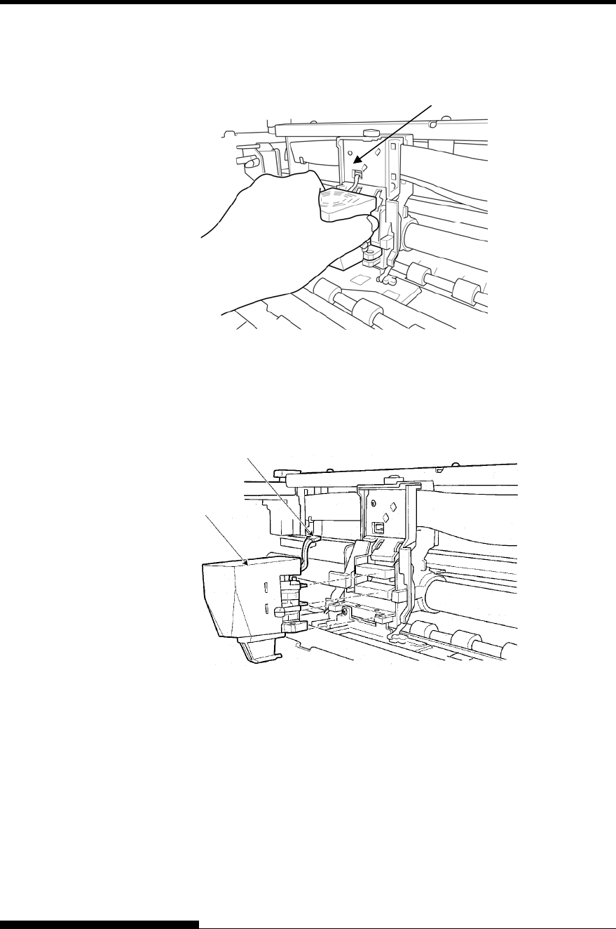
2. Open the front cover and control panel of the printer. Please
make sure that the print head stops at the ribbon replacement
position.
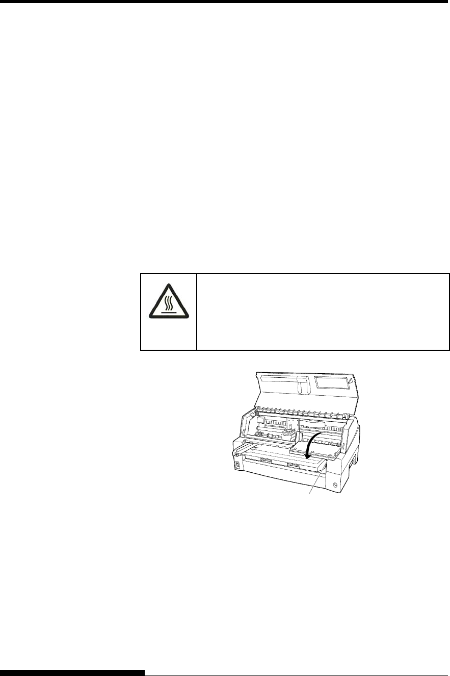
(HOT)
CAUTION <HOT>
The print head and metal frame is hot during printing
or immediately after printing. Do not touch them until
it cools down.
Preparing the printer to install the ribbon cartridge
REPLACING THE
RIBBON
Control
p
anel
MAINTENANCE
6-4 User's Manual
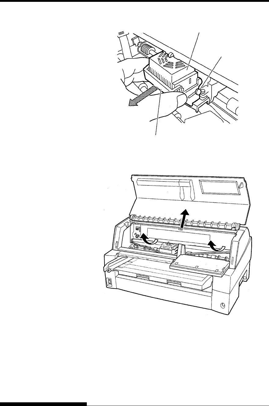
3. Remove the ribbon guide.
Removing the ribbon guide
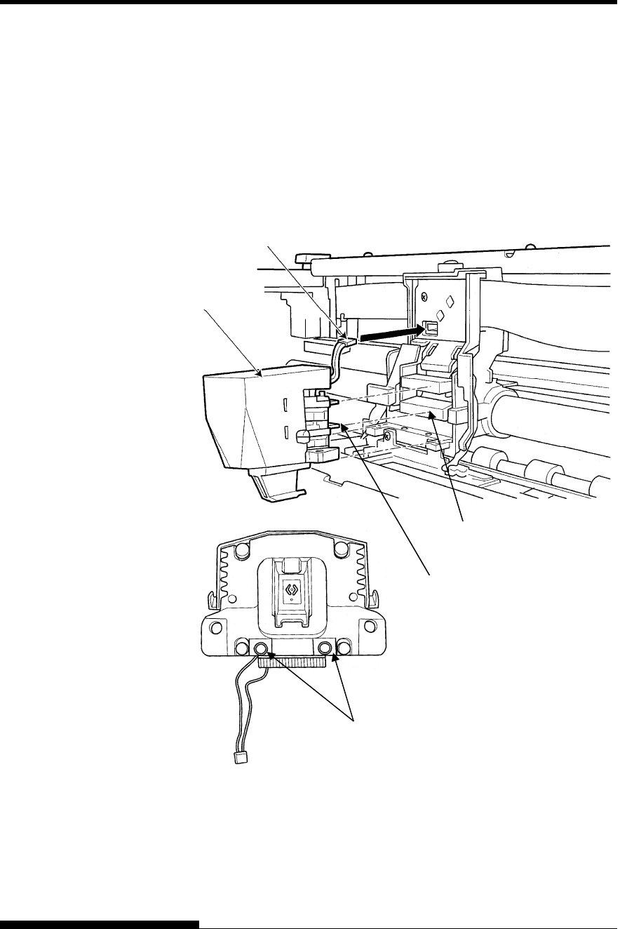
4. To remove the ribbon cassette, pull the under side of ribbon
cassette and carefully lift the cartridge out of the printer.
Removing the ribbon cassette
MAINTENANCE
User's Manual 6-5
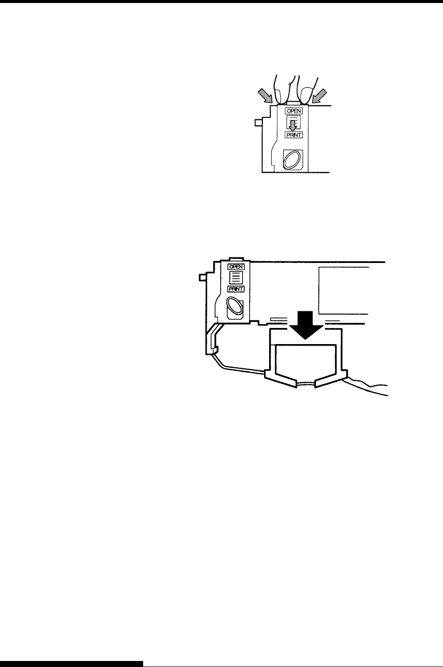
5. Remove the new ribbon cassette from its package. Push in the two
ribbon release tabs. The tabs snap into the cassette and the ribbon
feed mechanism engages.
Preparing the ribbon cassette
6. Remove the ribbon guide (green part) from the ribbon cassette.
Don’t turn the ribbon feed knob before installation.
Preparing the ribbon cassette
MAINTENANCE
6-6 User's Manual
7. Put the green ribbon guide into the space in front of print head. And
then place the mounting pins (both side of ribbon cassette) on the
slot of the printer cover. And then push the ribbon cassette so that
the ribbon cassette is installed vertically.
Installing the ribbon cassette
Mounting pin
Mounting pin
Ribbon guide
Print head Space Slot Slot
Push the ribbon cassette until it
clicks.
MAINTENANCE
User's Manual 6-7
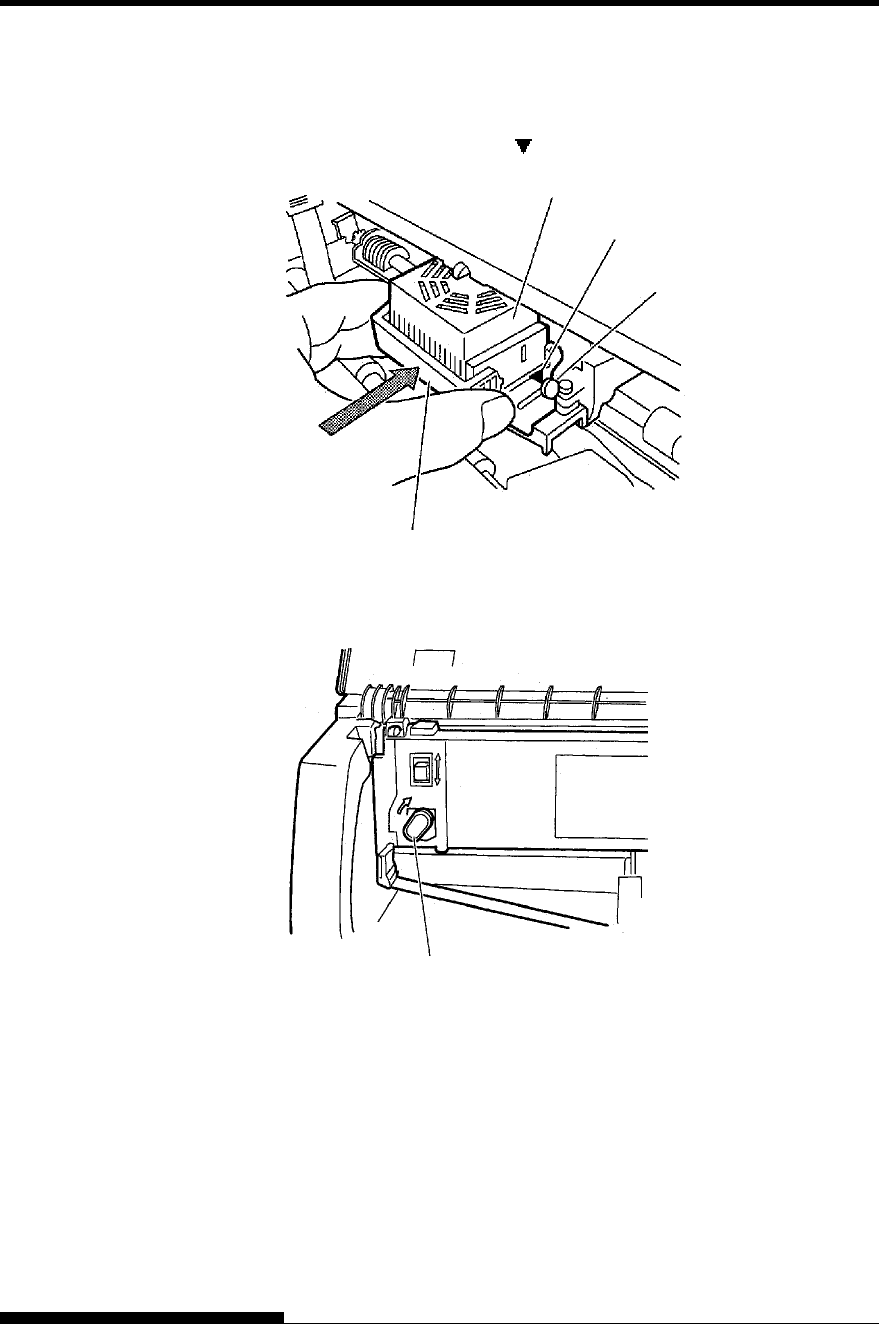
8. Attach the green ribbon guide on the print head.
Please make sure that the ribbon slack lightly. (If the ribbon is
strained, it will quirk when installation.)Push the green ribbon guide
until the triangle mark ” ”meets the round projection of print head.
9. Turn the ribbon feed knob clockwise to take up any slack in the
ribbon.
10. Return the control panel..
11. Close the front cover.
NOTE
A Fujitsu ribbon cassette is recommended. Don’t use other cassettes.
If other cassettes are used, operating problems or a damage of the
print head may be caused.
Triangle mark
Projections
Print Head
Ribbon Guide
Knob
MAINTENANCE
6-8 User's Manual
The print head is easy to replace.
(HOT)
CAUTION <HOT>
The print head and metal frame is hot during printing
or immediately after printing. Do not touch them until
it cools down.
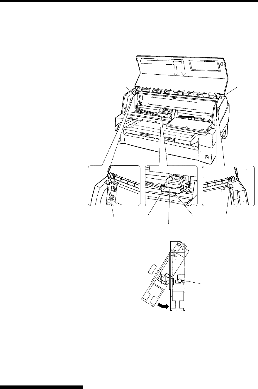
To remove the print head:
1. Turn off the printer.
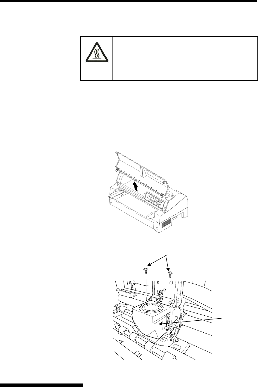
2. Open the front cover of the printer and remove the ribbon
cassette.
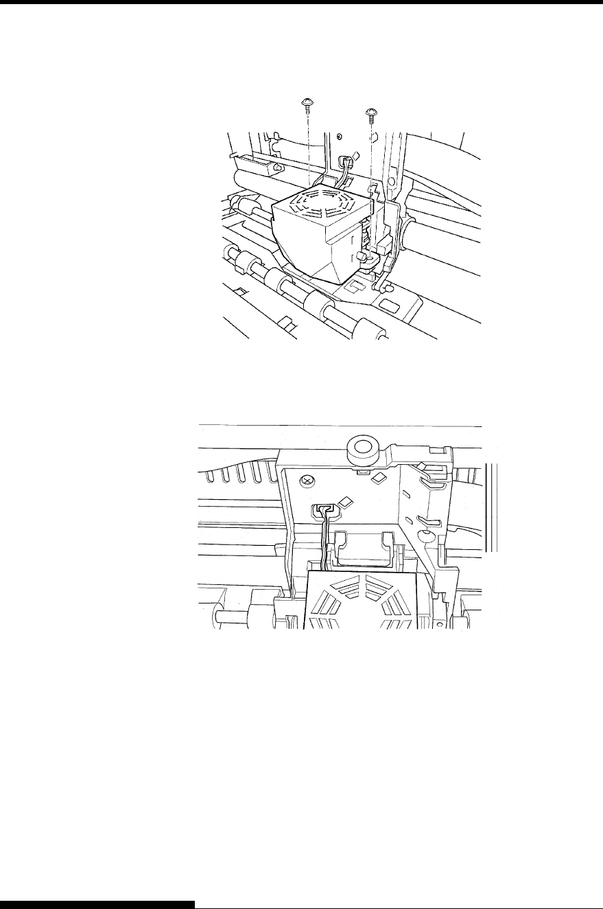
3. Please remove a front cover, during keeping the front cover
aslant.
4. Remove two screws.
REPLACING THE
PRINT HEAD
Screws
Print Head
MAINTENANCE
User's Manual 6-9
5. Remove the print head.
FAN connector
FAN connector
Print HD
MAINTENANCE
6-10 User's Manual
To install the print head:
1. Connect the lower connector to the lower card edge of the print
head.
2. Fit the upper card edge of the print head into the upper
connector.
3. Fit the mounting bosses of the print head into the holes on the
carriage.
4. Connect the fan connector.
NOTE
Be carefully to insert the card edge straightly.
Fan connector
Print head
Bosses of Print head
Lower connector
Lower card edge
MAINTENANCE
User's Manual 6-11
4. Fix the print head by two screws..
5. Insert the fan cables under black plastic part.
NOTE
If the FAN cable protrude from black plastic part. FAN cable may
be damaged by ribbon feed mechanism on left side frame.
MAINTENANCE
6-12 User's Manual
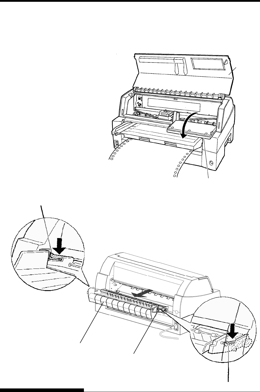
Opening and closing the control panel
The control panel of this printer can be pulled down toward the front as
necessary, such as when jammed paper must be removed.
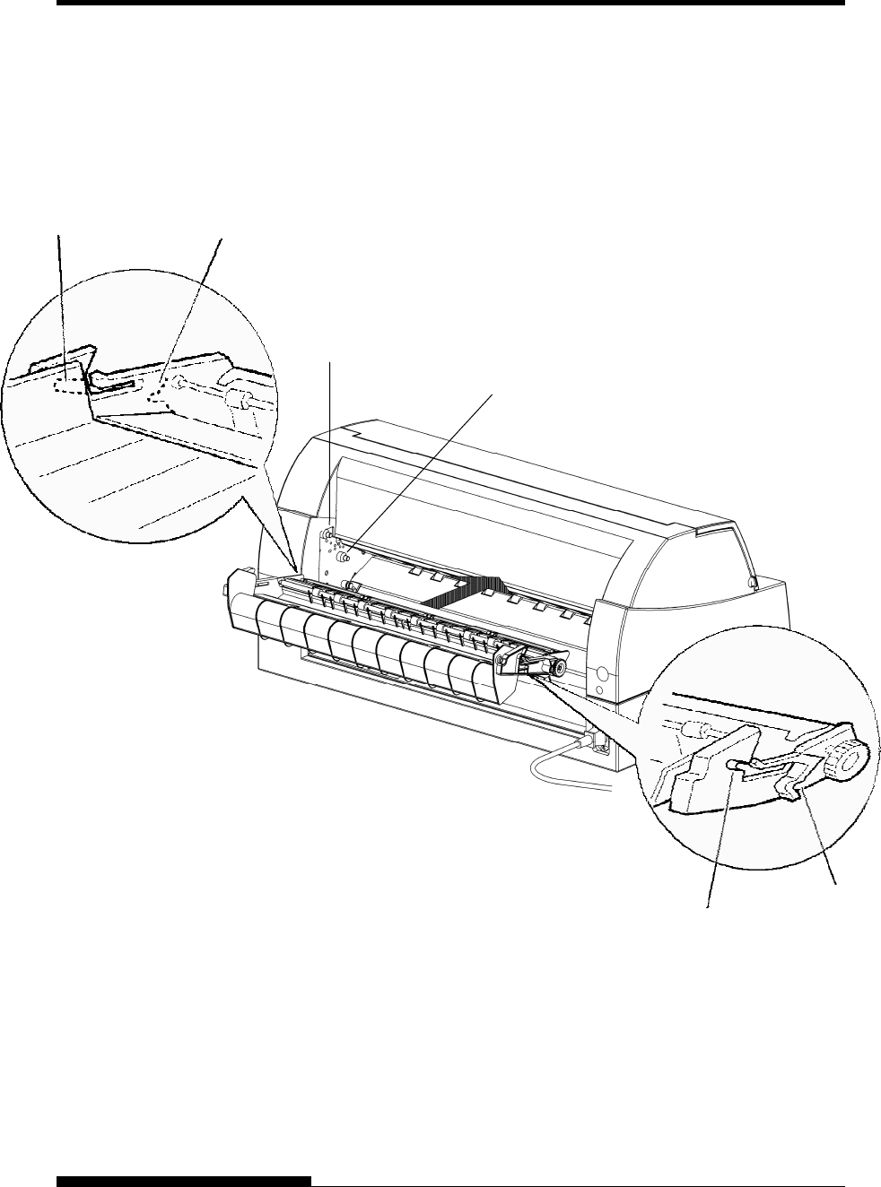
Removing the stacker unit
The stacker unit of this printer can be removed in the event that paper is
jammed in it unit.
While pushing down the lock levers of the stacker guide, pull out the
stacker unit from the rear.
Lock lever
Front cover
Control Panel
Stacker guide
Lock lever
Stacker
MAINTENANCE
User's Manual 6-13
Mounting the stacker unit
Position groove 1 over guide pin 1 on the right and left sides of the
stacker unit. Then, push in the stacker unit until guide pin 2 is hooked
onto slot 2.
Guide pin 2
Guide pin 1
Groove 1 Slot 2
Groove 1
Slot 2

MAINTENANCE
6-14 User's Manual

User's Manual 7-1
7
CHAPTER 7 TROUBLE-SHOOTING
TROUBLE-SHOOTING
Your printer is extremely reliable, but occasional
problems may occur. You can solve many of
these problems yourself, using this chapter.
If you encounter problems that you cannot resolve,
contact your dealer for assistance.
This chapter is organized as follows:
• Solving problems
• Diagnostic functions
• Getting help
The tables in this section describe common printer problems and their
solutions. The following types of problems are considered:
• Print quality problems
• Paper handling problems
• Operating problems
• Printer failures
Print Quality Problems
Poor print quality or other printing problems are often caused by
incorrect printer setup or incorrect software settings. A gradual decrease
in print quality usually indicates a worn ribbon. Table 7.1 identifies
common print quality problems and suggests solutions.
SOLVING
PROBLEMS

TROUBLE-SHOOTING
7-2 User's Manual
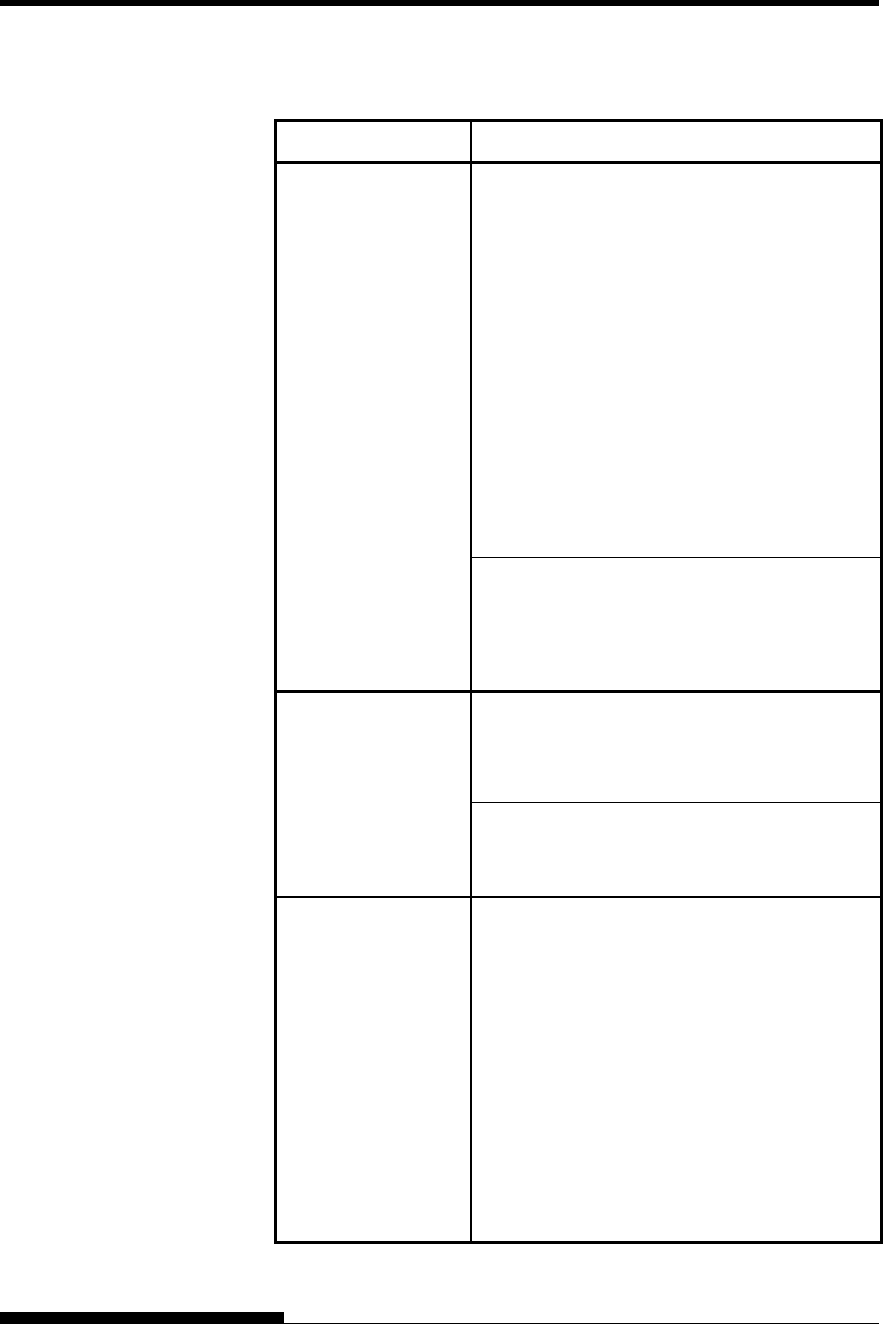
Table 7.1 Print Quality Problems and Solutions
Problem Solution
Make sure that the ribbon cartridge is
properly installed and that the ribbon feeds
smoothly.
Check ribbon wear. Replace the ribbon if
necessary.
Check the difference of thickness of
medium. If auto adjustment function detects
difference level of medium, it doesn’t work
properly. In this case you must adjust for
paper thickness manually. See ADJUSTING
PAPER THICKNESS in Chapter 3.
Printing is too light or
too dark.
If you adjust for paper thickness manually,
tune-up as follows.
If printing is too light, decrease setting.
If printing is dark, increase setting.
Note
Printer accepts the value for paper thickness
from Printer Driver or application program.
In this case, check the setting of the Printer
Driver or application program at your host
computer. And then tune the value by way
above.
Stains or smudges
appear on the page.
Check ribbon wear. Replace the ribbon if
necessary.
Check whether the tip of the print head is
dirty.
Clean the head with a soft cloth if necessary.
The page is blank. Make sure that the ribbon cartridge is
properly installed.
Printing is erratic or the
wrong characters are
printed. One or more
“?” characters are
printed.
Make sure that the interface cable is securely
connected to both the printer and computer.
Make sure that the printer emulation selected
in your software is the same as the emulation
selected on the printer. See the section
Selecting an Emulation in Chapter 2.
If you are using an RS-232C serial interface,
make sure that the serial settings required by
your software or computer are the same as
the settings on the printer. See the section
Hardware Items and Options in Chapter 5.
TROUBLE-SHOOTING
User's Manual 7-3
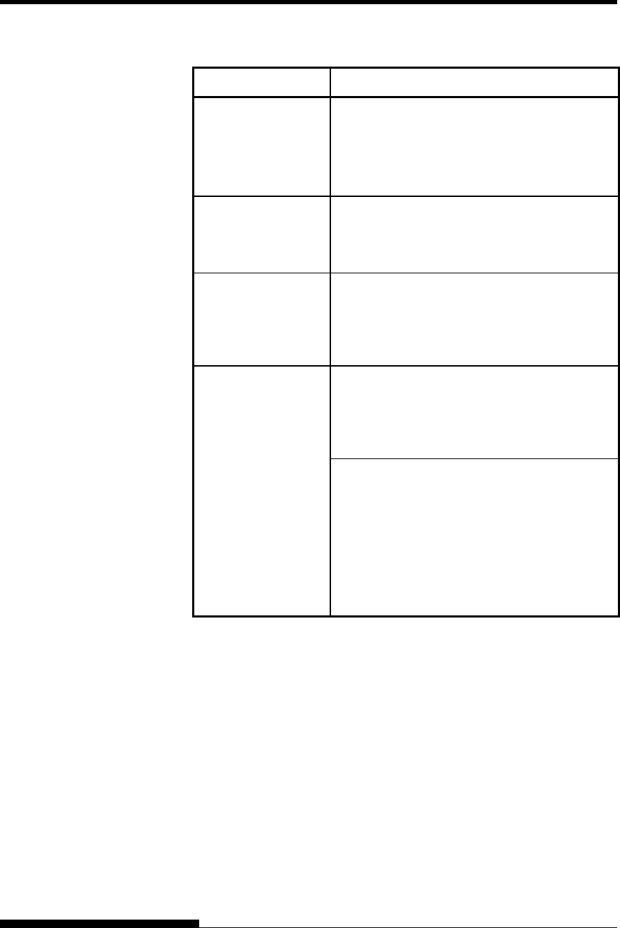
Table 7.1 Print Quality Problems and Solutions (Cont.)
Problem Solution
If lost area is about 10mm (3mm) from left and
right edge of continuous forms(single sheet),
Area-over detection control woks properly.
In this case make sure that paper size, paper
position, and left and right margins are properly
set. See the section Configuration Items and
Options in Chapter 5.
Note
Preprinted dark color area, shape of corner cut,
paper skew may cause incorrect detection.
Please don’t use medium like this.
If you must use medium like this absolutely,
you can disable Area-over detection by using
setup mode. But risk of print head broken is
increase.
Characters are lost at
the left or right end.
Incorrect paper size selection of the Printer
Driver causes right side area is lost (exactly
Printer Driver divide the page by paper size
setting and postpone divided right page). Please
check the paper size setting.
Use the printer’s V-ALMNT function to check
the vertical print alignment. If necessary, adjust
the print alignment. See the section Using the
Diagnostic Functions in Chapter 5.
Printing is vertically
misaligned (jagged).
Smaller adjustment for paper thickness causes
vertically misalignment too.
Please refer to Printing is too light or too dark.
The top margin is
wrong.
The top margin is the sum of the top-of-form
setting, the software-specified top margin, and
the printer’s TOP-MRG setting. Proceed as
follows:
• Make sure that the top-of-form setting is
correct. The factory default is 25.4 mm (1
inch). See the section Changing Top-of
Form in Chapter 5.
• Check the software-specified top margin.
Refer to your software documentation.
• Check the printer’s TOP-MRG setting. See
the section MENU1 and MENU2 Items
and Options in Chapter 5.
TROUBLE-SHOOTING
7-4 User's Manual
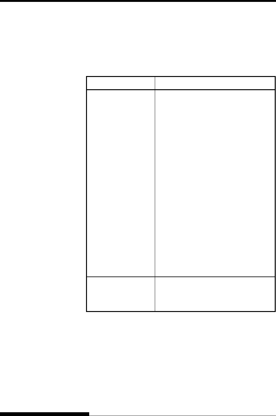
Table 7.1 Print Quality Problems and Solutions (Cont.)
Problem Solution
Lines are double
spaced instead of
single spaced.
Check the line spacing setting in your software.
Change the CR-CODE setting in the printer
setup mode to CR ONLY. See the section
MENU1 and MENU2 Items and Options in
Chapter 5.
The printer
overprints on the
same line.
Change the CR-CODE setting in the printer
setup mode to CR & LF. See the section
MENU1 and MENU2 Items and Options in
Chapter 5.
The next print line
starts where the
previous line ended
instead of at the left
margin.
Change the LF-CODE setting in the printer
setup mode to LF & CR. See the section
MENU1 and MENU2 Items and Options in
Chapter 5.
Variation of the top of form is saturated in a few
pages and displacement is about 1mm or less. In
this case adjust value is prepared in setup mode.
See ADJUST Items and Options and search
<FCNTADJ> or <RCNTADJ>.
The top of form of
continuous form
displaces gradually.
Variation of the top of form isn’t saturated. In
this case setting of page length isn’t correct.
Make sure that page length setting equal actual
page length exactly.
In general page length of continuous form is
multiple of 0.5inch. Anyway don’t set page
length of continuous forms using mm unit.
TROUBLE-SHOOTING
User's Manual 7-5
Paper Handling Problems
Table 7.2 describes common paper handling problems and suggests
solutions. See Chapter 3 for detailed procedures on loading and using
paper.
Table 7.2 Paper Handling Problems and Solutions
Problem Solution
Paper cannot be loaded
or fed.
Make sure that the paper path indicator
(FRONT TRACTOR, REAR TRACTOR,
CUT SHEET) lights correctly.
Press the PAPER PATH button to select the
paper path.
Make sure that the paper covers the paper-
out sensor, i.e., the left paper edge is within
52 mm for single sheets or 41 mm for
continuous forms from the left edge of the
platen. (This problem cannot occur if you
use the forms tractor unit or insert a single
sheet with its left edge in contact
with the left paper guide.)
Make sure that the tractor unit is correctly
installed and that the tractor shaft gear
engages the platen shaft gear.
If you are using a cut sheet feeder, make
sure that the bin lever is set to the
“CLOSED” position. (The bin lever is on the
left side of the feeder.)
If you are using a cut sheet feeder, make
sure that the feeder is firmly mounted on the
printer and the cable is correctly connected.
Paper manually loaded
is ejected without
printing
If you are using the paper skew detection
(option), adjust the paper guide on the paper
table for the print start position and correctly
slide the sheet along the guide.
TROUBLE-SHOOTING
7-6 User's Manual
Table 7.2 Paper Handling Problems and Solutions (Cont.)
Problem Solution
Paper jams while
loading.
Turn off the printer and remove the jammed
paper. Remove any obstructions from the paper
path.
If you are using a cut sheet feeder, make sure
that the bin lever is set to the “CLOSED”
position. (The bin lever is on the left side of the
feeder.)
Make sure that the paper is not folded, creased,
or torn.
Reload the paper.
Make sure that the paper table is in normal
mode. Set the paper table to normal mode.
Paper jams while
printing.
Turn off the printer and remove the jammed
paper. Remove any obstructions from the paper
path.
For continuous forms, make sure that the
incoming and outgoing paper stacks are
correctly placed. Paper should feed straight.
Make sure that the paper table is in normal
mode. Set the paper table to normal mode.
If you are using a cut sheet feeder, make sure
that the bin lever is set to the “CLOSED”
position. (The bin lever is on the left side of the
feeder.)
Reload the paper.
Paper slips off the
forms tractors or the
perforated holes of
the paper tear during
printing.
Make sure that the forms tractors are positioned
correctly for the width of your paper and that
the perforated holes of the paper fit directly over
the tractor sprockets.
TROUBLE-SHOOTING
User's Manual 7-7
Operating Problems
Table 7.3 identifies common operating problems and suggests solutions.
If you cannot resolve a problem, contact your dealer.
Table 7.3 Operating Problems and Solutions
Problem Solution
The power does not
turn on.
Make sure that the “I” on the printer power
switch is depressed.
Make sure that the power cord is securely
connected to both the printer and the outlet.
Make sure that the power outlet is functional.
Turn the power off. Wait 100 seconds and
then turn the printer on again. If the printer
still has no power, contact your dealer.
The printer is on but it
will not print.
Make sure that the printer is online.
Make sure that the interface cable is securely
connected to both the printer and the
computer.
If the red PAPER OUT indicator is lit, load
paper.
Run the printer self-test (see Chapter 5). If the
self-test executes normally, the problem is
caused by the interface, the computer,
incorrect printer settings, or incorrect software
settings.
Make sure that the printer emulation selected
in your software is the same as the emulation
selected on the printer. See the section
Selecting an Emulation in Chapter 2.
Make sure that the front cover is completely
closed.
If you are using an RS-232C serial interface,
make sure that the serial settings required by
your software or computer are the same as the
settings on the printer. See the section
Hardware Items and Options in Chapter 5.
The cut sheet feeder
does not operate.
Make sure that the cut sheet feeder is firmly
mounted on the printer.
Make sure that the cable is correctly
connected.
The FRONT DIR
indicator blinks.
Remove the printed sheet of paper from the
paper table.

TROUBLE-SHOOTING
7-8 User's Manual
Printer Failures
A user cannot generally resolve a problem involving defective printer
hardware. On detecting a fatal error, the printer will:
• Stop printing
• Beep four times
• Turn the ONLINE indicator off
The control panel displays alarms. The meanings of alarms can be
checked in the following table.
TROUBLE-SHOOTING
User's Manual 7-9
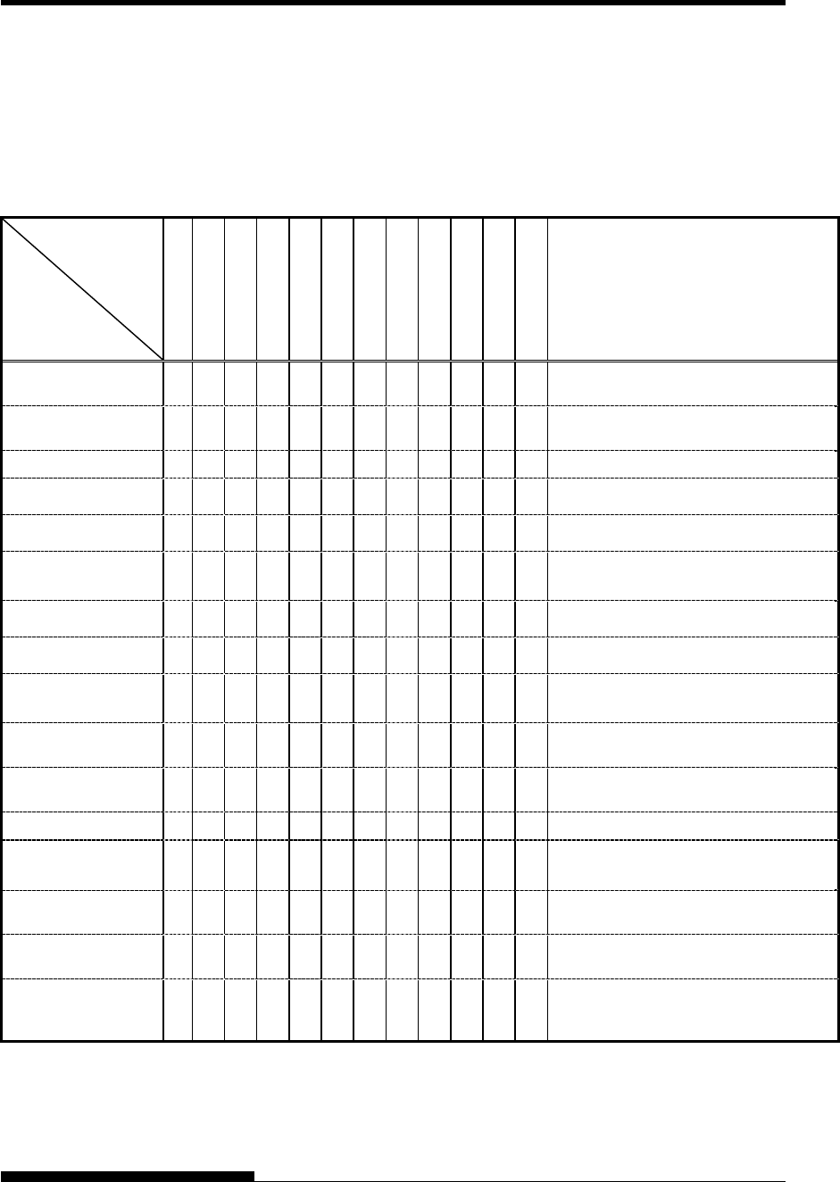
Alarm display function(LED)
This printer has a function for distinguishing between alarms by using
the blinking of individual lamps on the control panel.
From the combination of blinking lamps in an alarm state, the meaning
of the alarm can be determined as shown in the following table.
Lamp
Alarm name
PAPER OUT
REMOVE PAPER
FRONT DIR
QUIET
AUTO GAP
HI IMPACT
TRACTOR F
TRACTOR R
CUT SHEET
MENU1
MENU2
ONLINE
Condition of occurrence
LES alarm
LES could not be detected during the space initial
operation.
Space problem alarm
The shield board could not be detected normally
by the LRES sensor.
Fan alarm
The cooling fan could not rotate.
Fire check alarm
SP motor
Abnormally high current of motor driver was
detected.
Fire check alarm
Ribbon motor
Abnormally high current of motor driver was
detected.
HCPP (cut sheet or
continuous forms paper
switching) alarm
Switching between cut sheet paper and
continuous forms paper was not possible.
Fire check alarm
LF motor
Abnormally high current of motor driver was
detected.
Fire check alarm
CSF motor
Abnormally high current of motor driver was
detected.
Overload alarm
An overload occurred during printing, and second
pass printing was performed. However, the
power source voltage was not restored.
Low voltage alarm
The power source voltage dropped below the
specified level when no printing was in progress.
Fire check alarm
Print Head
Abnormally high current or long driving of print
head driver was detected.
Over voltage alarm
Over voltage of power source was detected.
APTC gap alarm
During the APTC operation, paper was detected
immediately after the start of approach motion, or
no paper was detected.
APTC hop position sensor
alarm
During the APTC operation, no reference
position was detected.
ROM/RAM alarm
A sum-check error or read/write error occurred,
or no CG-ROM is mounted.
Sector protect alarm
A sector protect check of flash ROM was
performed, but no sector protect information was
found.
: Blinking
Blank: Off
TROUBLE-SHOOTING
7-10 User's Manual
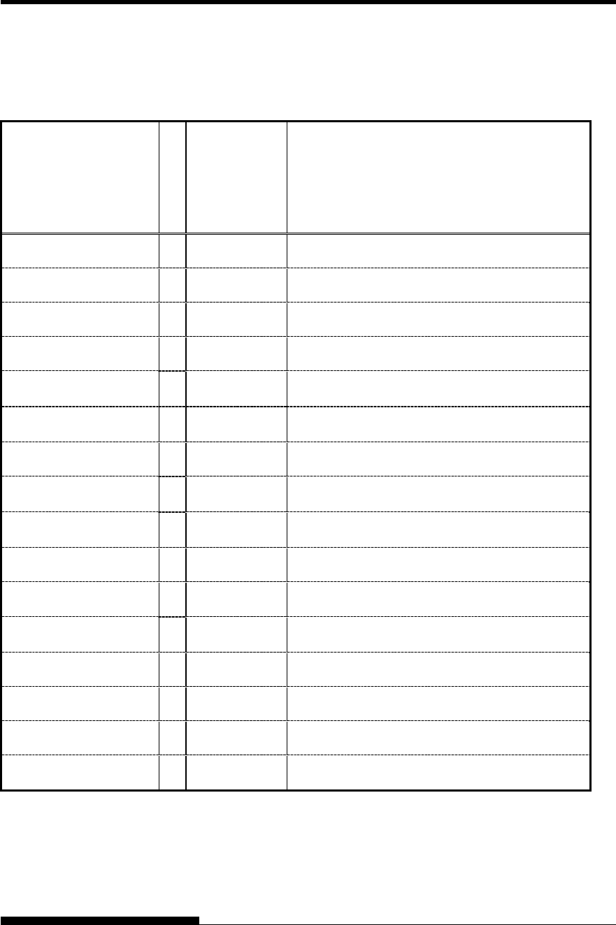
Alarm display function(LCD)
This printer has a function for distinguishing between alarms by using
the blinking of message lamp and LCD on the control panel.
Alarm name
Message Lamp
LCD Condition of occurrence
LES alarm FATAL!
LES ALARM
LES could not be detected during the space initial operation.
Space problem alarm FATAL!
SPACE ALARM
The shield board could not be detected normally by the LRES
sensor.
Fan alarm FATAL!
FAN ALARM
The cooling fan could not rotate.
Fire check alarm
SP motor
FATAL!
SPM ALARM
Abnormally high current of motor driver was detected.
Fire check alarm
Ribbon motor
FATAL!
RBFM ALARM
Abnormally high current of motor driver was detected.
HCPP (cut sheet or continuous
forms paper switching) alarm
FATAL!
HCPP ALARM
Switching between cut sheet paper and continuous forms paper
was not possible.
Fire check alarm
LF motor
FATAL!
LFM ALARM
Abnormally high current of motor driver was detected.
Fire check alarm
CSF motor
FATAL!
CSFM ALARM
Abnormally high current of motor driver was detected.
Overload alarm FATAL!
OVERLOAD ALARM
An overload occurred during printing, and tripartite printing was
performed. However, the power source voltage was not restored.
Low voltage alarm FATAL!
LOW VOLT ALARM
The power source voltage dropped below the specified level when
no printing was in progress.
Fire check alarm
FATAL!
HEAD ALARM
Abnormally high current or long driving of print head driver was
detected.
High voltage alarm FATAL!
HIGH VOLT ALARM
Over voltage of power source was detected.
APTC gap alarm FATAL!
APTC GAP ALARM
During the APTC operation, paper was detected immediately after
the start of approach motion, or no paper was detected.
APTC home position sensor
alarm
FATAL!
APTC HPS ALARM
During the APTC operation, no reference position was detected.
ROM/RAM alarm FATAL!
ROM/RAM ALARM
A sum-check error or read/write error occurred, or no CG-ROM is
mounted.
Sector protect alarm FATAL!
F-ROM ALARM
A sector protect check of flash ROM was performed, but no sector
protect information was found.
: Blinking
Blank: Off
TROUBLE-SHOOTING
User's Manual 7-11
Responses to alarm occurrences
Your first response to each alarm should be as described in the following
table.
Problem Solution
LES alarm Remove any paper dust, which may cause problems
in carriage operation.
Space problem
alarm
Same solution same as above should be done.
Check adjustment for paper thickness.
Smaller setting causes spacing problem.
Fan alarm Remove any dust of ventilation near the Fan motor.
APTC gap
alarm
Check the paper thickness (0.04 to 0.65 mm).
Check whether the paper has different thicknesses
or whether the paper has filing holes.
For problems other than the above, request your printer dealer to make
repairs.
Especially Fire Check is happen, please refrain using printer.
The printer diagnostic functions are SELF-TST, HEX-DUMP, and V-
ALMNT.
• SELF-TST tells you whether the printer hardware is functioning
correctly. If the printer hardware is functional, any problems
you are having are probably caused by incorrect printer settings,
incorrect software settings, the interface, or the computer.
• HEX-DUMP allows you to determine whether the computer is
sending the correct commands to the printer, and whether the
printer is executing the commands correctly. This function is
useful to programmers or others who understand how to
interpret hex dumps.
• V-ALMNT allows you to check and, if necessary, correct the
printer’s vertical print alignment.
For details on using these functions, all of which are available in the
printer setup mode, see the section Using the Diagnostic Functions in
Chapter 5.
If you are not able to correct a problem using this chapter, contact your
dealer for assistance. Be prepared to provide the following information:
• Your printer model number, serial number, and date of
manufacture. Look for this information on the rating label at the
back of the printer.
• Description of the problem
DIAGNOSTIC
FUNCTIONS
GETTING HELP

TROUBLE-SHOOTING
7-12 User's Manual
• Type of interface you are using
• Names of your software packages
• List of the printer default settings. To print the default settings,
see the section Printing a List of Selected Options in Chapter
5.

User's Manual 8-1
8
CHAPTER 8 INSTALLING OPTIONS
INSTALLING OPTIONS
The installaion of options allows you to expand
the capabilities of your printer. Options available
for the printer include:
• LAN card
• Cut sheet feeder
• Tractor unit
• Large stacker
• Large Paper Table
The LAN card is a user installable option, but can be installed only on a
printer model with the parallel and USB interfaces. For information on
the installation procedure, refer to the manual that comes with the LAN
card.
Options can be purchased from your dealer. Order numbers for options
are given in Appendix A.
This chapter describes what to do after installing cut sheet feeder.
A cut sheet feeder (SF940) allows you to automatically feed single sheets.
It can be mounted on the front or the rear of the printer.
When attaching the cut sheet feeder to the front of the printer, removing
the tractor and replacing soundproof cover with large or small paper table
are necessary.
For both front and rear, the cut sheet feeder can handle a max. of 5-ply
multipart media.
When installing the front and rear cut sheet feeders, the printer assigns
the first bin to the front feeder. You can change the assignment using set
up mode.
WARNING Electric
shock Before mounting or
removing the cut sheet
feeder, turn off the power
switches of the personal
computer and the printer
and remove the power plug
from the outlet.
Otherwise, you may
receive electric shock.
INSTALLING THE
CUT SHEET
FEEDER
INSTALLING OPTIONS
8-2 User's Manual
Installing on the front side of the printer
1. Turn off the printer power.
Confirm that the printer power is turned to the { side.
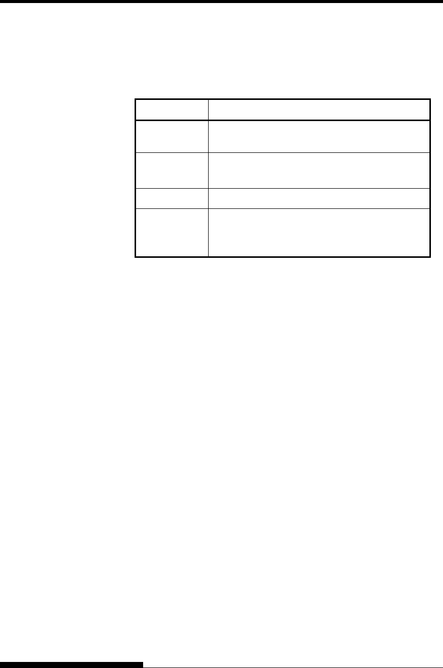
2. Removing the tractor unit
Raise the paper table and remove the tractor unit. (For details
on mounting and removing the tractor unit, see “Selecting the
Tractor Unit Position” on page 2-10.)
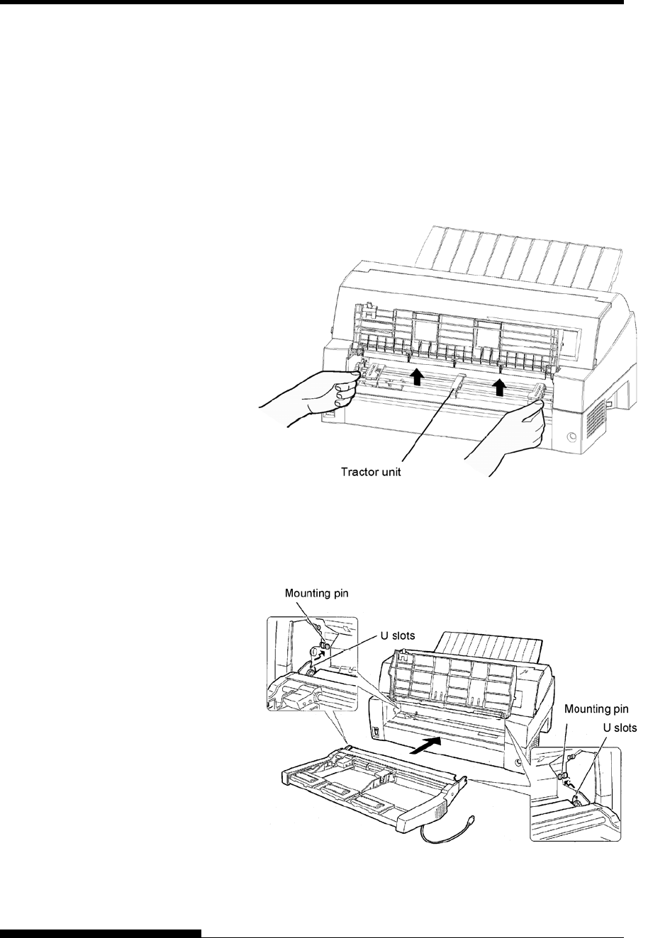
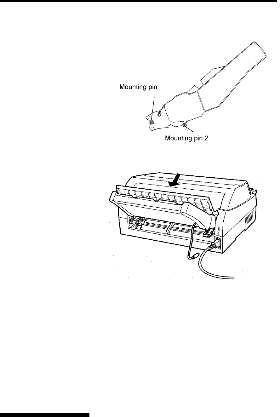
3. Installing the cut sheet feeder
Adjust the U slots made on both sides of the cut sheet feeder to
the mounting pins inside the printer and lower the cut sheet
feeder slowly.
Check that the cut sheet feeder frame is correctly mounted on
mounting pin 2.
INSTALLING OPTIONS
User's Manual 8-3
4. Replacing the paper table
Be sure to replace the paper table. (See “Setting the paper
table” on page 2-5.)
If the paper table is incorrectly set, a paper jam may occur.
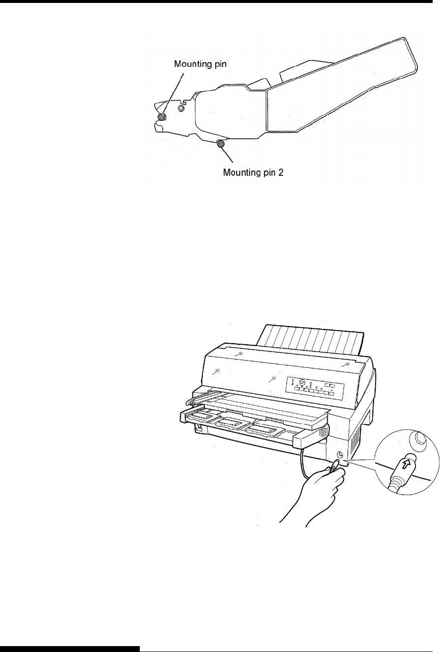
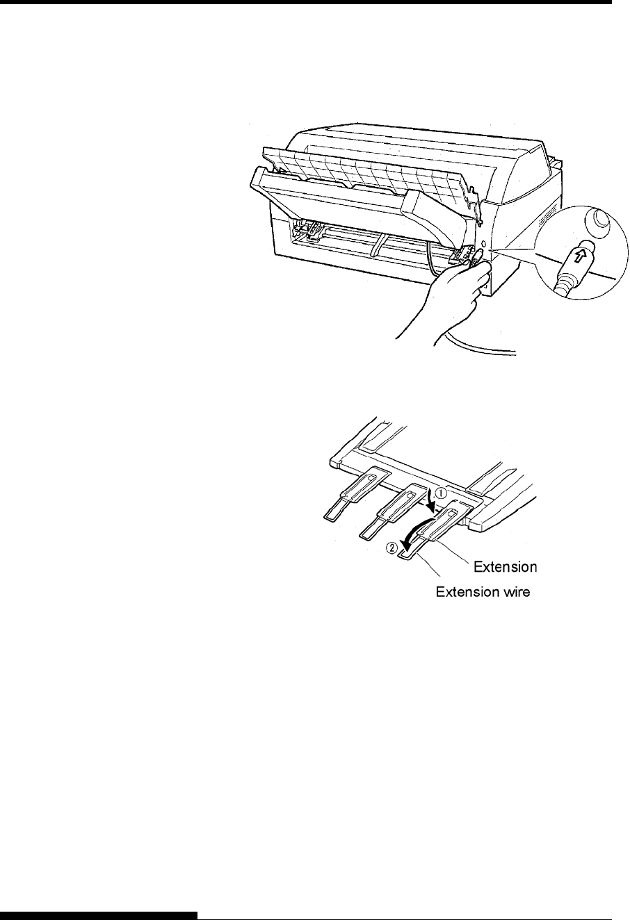
5. Connecting the cable
Connect the cut sheet feeder cable to the connector on the front
right of the printer. Insert the cable with the connector arrow
mark up.
INSTALLING OPTIONS
8-4 User's Manual
6. Extend the extension and extension wire in the order from
(1) to (2) according to the size of the paper to be used.
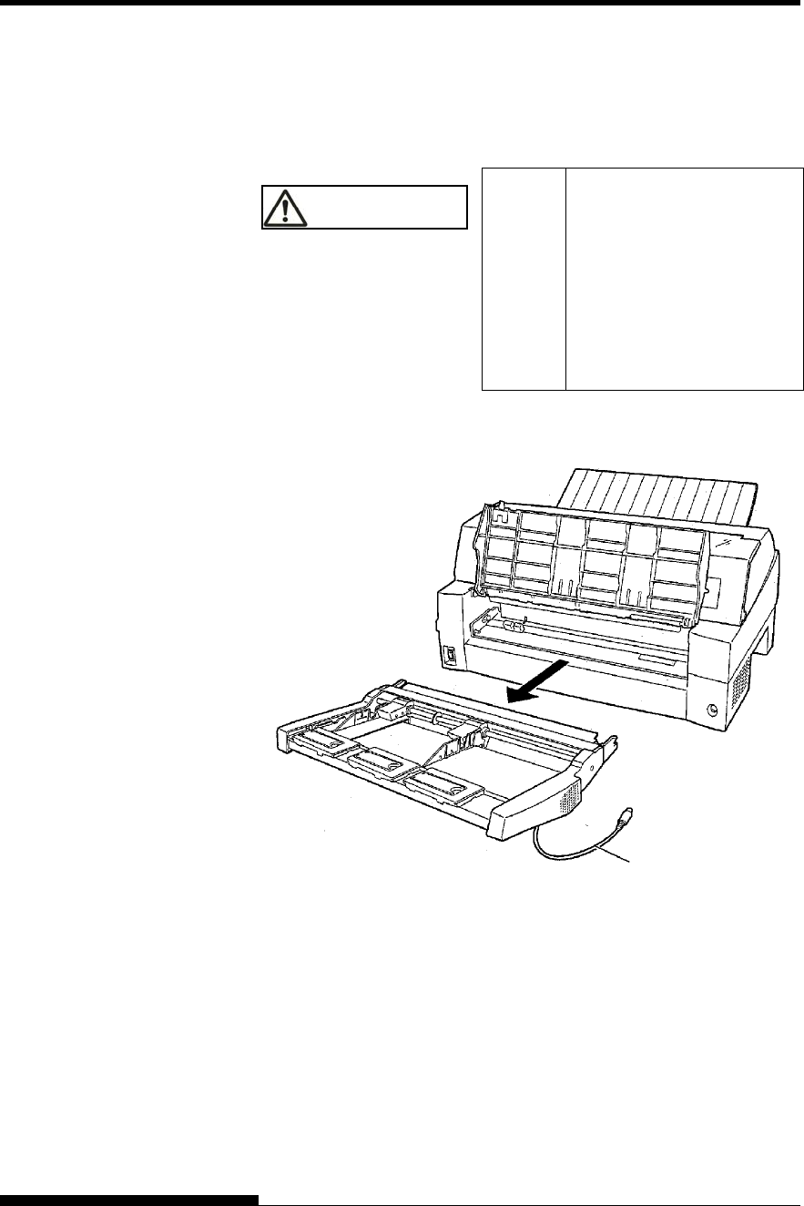
Installing on the rear side of the printer
Before mounting the cut sheet feeder, turn off the printer power.
1. Turn off the printer power.
Confirm that the printer power is turned to the O side.
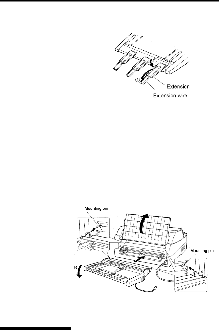
2. Installing the cut sheet feeder
Open the rear stacker. Hold both sides of the cut sheet feeder
and adjust the U slots made on both side of the cut sheet feeder
to the mounting pins inside the printer. (Attach the slots with
the letter A of the cut sheet feeder adjusted to that on the printer
side.) Then, lower the cut sheet feeder like it turns in the
direction of arrow B, using the mounting pins as supporting
points.
INSTALLING OPTIONS
User's Manual 8-5
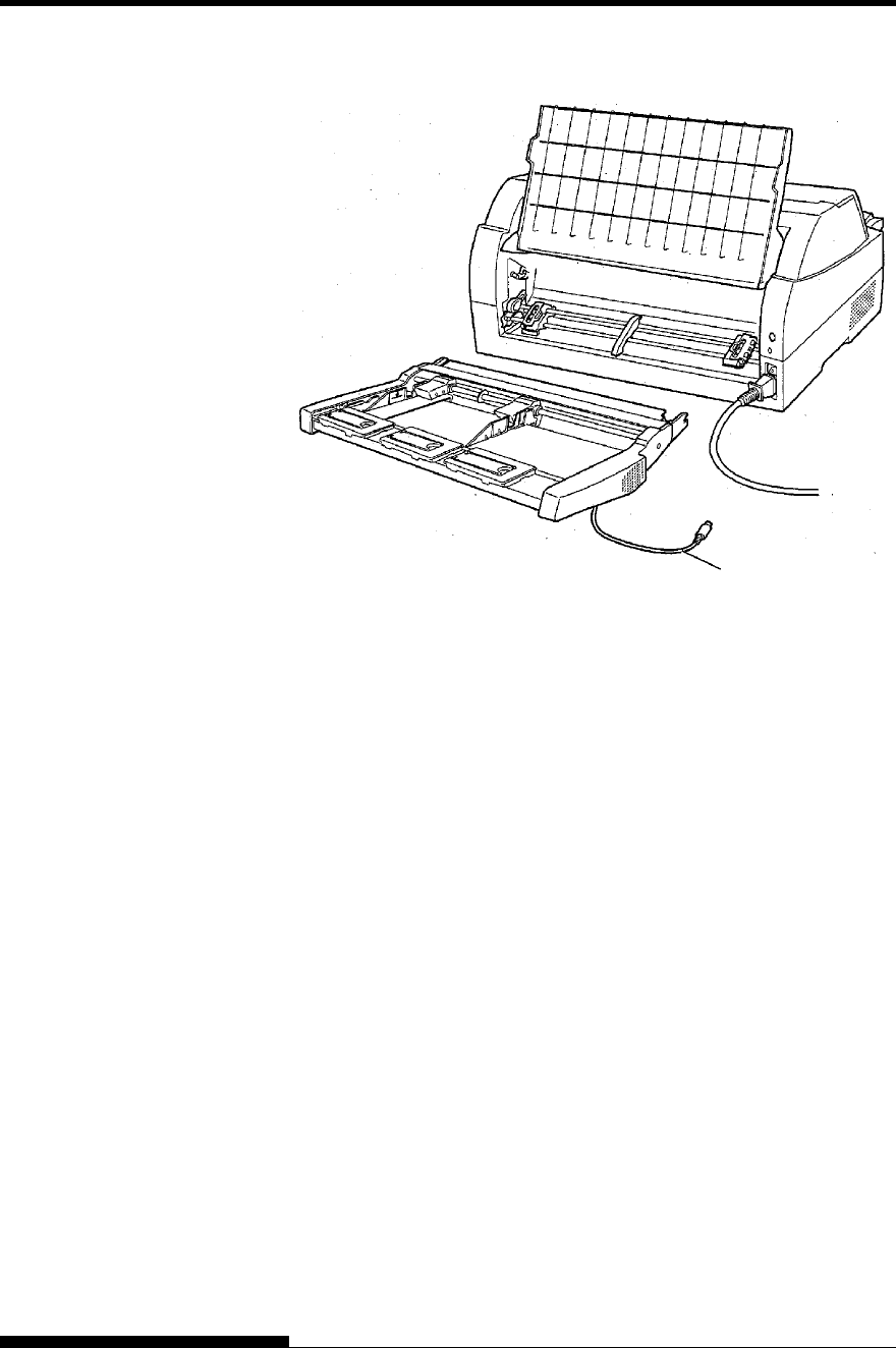
Check that the cut sheet feeder frame is correctly mounted on
mounting pin 2.
3. Close the rear stacker.
INSTALLING OPTIONS
8-6 User's Manual
4. Connecting the cable
Connect the cut sheet feeder cable to the connector on the rear
right of the printer. Insert the cable with the connector arrow
mark up.
5. Extend the extension and extension wire in the order from
(1) to (2) according to the size of the paper to be used
INSTALLING OPTIONS
User's Manual 8-7
Removing the Cut Sheet Feeder
Before removing the cut sheet feeder, disconnect the cable.
WARNING Electric
shock Before mounting or
removing the cut sheet
feeder, turn off the power
switches of the personal
computer and the printer
and remove the power plug
from the outlet. Otherwise,
you may receive electric
shock.
When mounted on the front side of the printer
Cable
INSTALLING OPTIONS
8-8 User's Manual
When mounted on the rear side of the printer
A tractor unit is supplied as standard equipment attached to the front of
the printer.
This unit may also be attached to the rear of the printer for rear feeding
of continuous forms.
For details on removing and mounting the tractor unit, see “Selecting the
Tractor Unit Position” on page 2-10.
INSTALLING THE
TRACTOR UNIT
Cable
INSTALLING OPTIONS
User's Manual 8-9
To continuously stack cut sheets or eject long cut sheets to the rear,
mount the large stacker.
Also, if a cut sheet feeder is mounted at the rear, the stacker must be
replaced with the large stacker even if cut sheets need not be
continuously stacked.
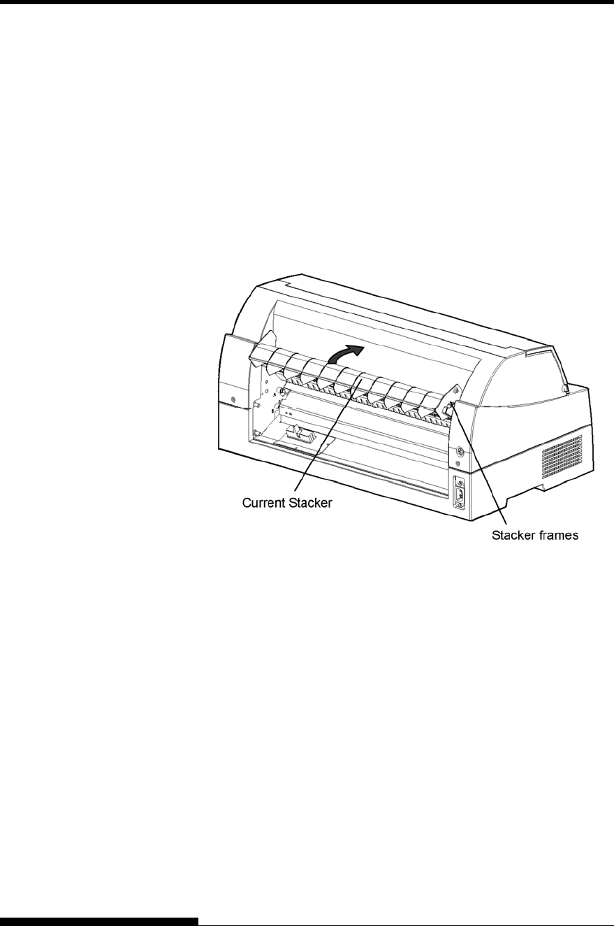
1 Removing the current stacker
1. Lift up the current stacker in the direction indicated by the arrow.
2. With the stacker in the condition described in step 1, push out
the right and left stacker frames to separate them from the
protrusions on the stacker plate.
INSTALLING THE
LARGE STACKER
INSTALLING OPTIONS
8-10 User's Manual
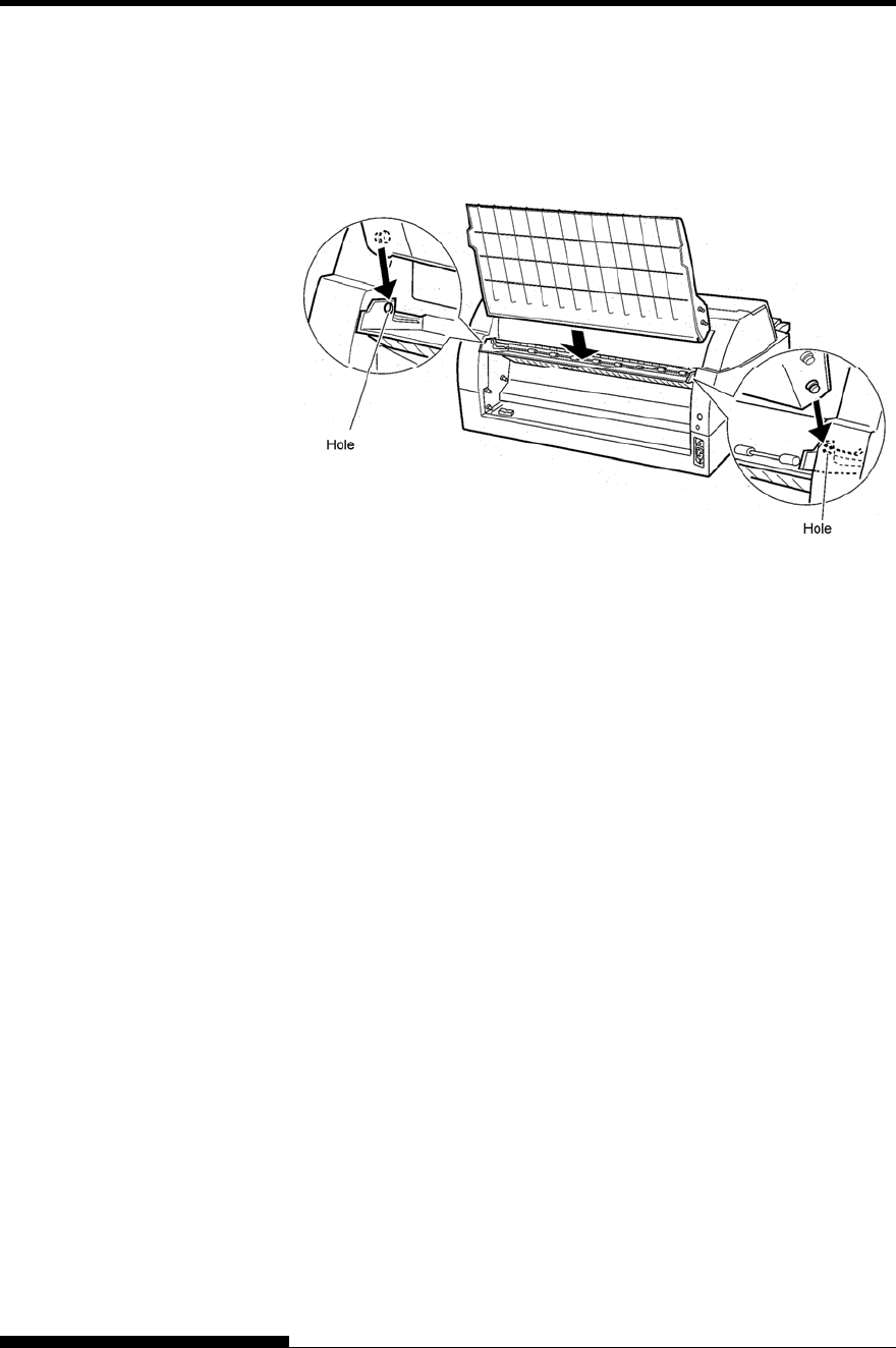
2 Mounting the rear stacker
At the rear of the printer, push the protrusions on both sides of the
rear stacker into the holes inside the rear stacker guide as shown in
the following figure.
INSTALLING OPTIONS
User's Manual 8-11
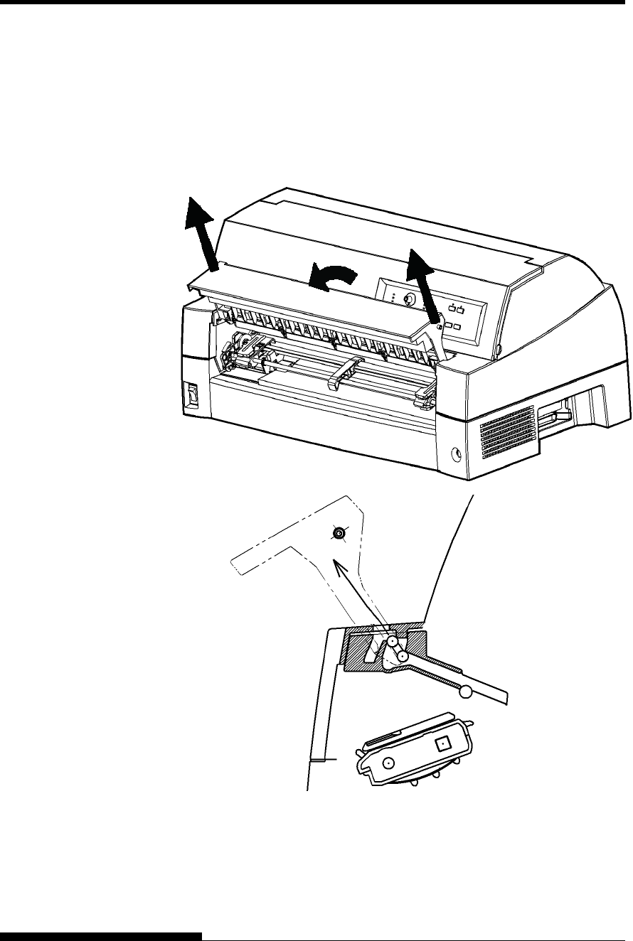
To use long cut sheets, mount the large cut sheet table.
1 Removing the soundproof cover
After opening the soundproof cover and adjusting it to a tilted
position, remove the paper table by pulling it to separate the left and
right protrusions on the soundproof cover ends from the grooves on
the cover.
INSTALLING THE
LARGE PAPER
TABLE
INSTALLING OPTIONS
8-12 User's Manual
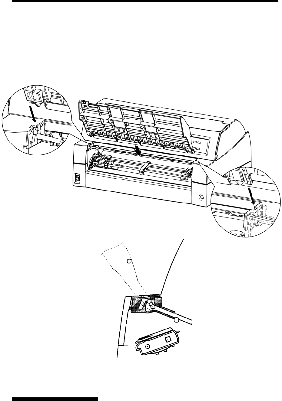
2. Installing the Large Paper Table
Insert and push the left and right protrusions on the paper table
ends into the grooves on the cover as shown in the following
figure. Set the paper table in the normal position. (See “Setting
the paper table” in Chapter 2.)
The new large paper table can be opened or closed in the same
way as the removed paper table.
Make sure the protrusions
are inserted completely as
right figure.
User's Manual A-1
A
APPENDIX A SUPPLIES AND OPTIONS
SUPPLIES AND OPTIONS
This appendix lists the supplies and options available
for the printer.
Contact your dealer for information on ordering
any of these items.
Supplies Order Number
Ribbon cassette
Black ribbon CA05463-D807
Ribbon sub cassette
Black ribbon CA05463-D877
Print head KA02033-E223
Options Order Number Description
LAN card KA02012-C103 Installable only on
a printer model
with the parallel
and USB
interfaces.
Cut sheet feeder
(SF940)
KA02027-D750
Tractor Unit KA02038-E650
Large Stacker KA02038-D160
Large paper table KA02038-D150
Small paper table KA02039-D150
SUPPLIES
OPTIONS

SUPPLIES AND OPTIONS
A-2 User's Manual

User's Manual B-1
B
APPENDIX B PRINTER AND PAPER SPECIFICATIONS
PRINTER AND PAPER
SPECIFICATIONS
This appendix gives the physical, functional, and
performance specifications for the printer.
It also gives detailed paper specifications.
Dimensions
Height: 290 mm (11.4 in)
Width: 600 mm (23.6 in)
Depth: 350 mm (13.8 in)
Weight: 22.5 kg (50 lb)
AC power requirements
M33325A: 100 to 120 VAC ±10%; 50/60 Hz
M33325B: 220 to 240 VAC ±10%; 50/60 Hz
Power consumption
Model:M33325A
Average 485 VA
Maximum 820 VA
Model:M33325B
Average 360 VA
Maximum 810 VA
Heat generation Average 980 kJ/h
Interface Centronics parallel and RS-232C serial
Centronics parallel and USB and LAN (option).
Data buffer size 0, 256, 2K, 8K, 24K, 32K, 96K, or 128K bytes
Download buffer Maximum 128K bytes
(128K minus data buffer size)
Operating environment 5 to 38°C (41 to 100°F)
30% to 80% RH (no condensation)
Wetbulb temperature, less than 29°C (84°F)
Storage environment -15 to 60°C (-4 to 140°F)
10% to 95% RH (no condensation)
Acoustic noise Average _ _ dB (A)
ISO 7779 (Bystander Position-Front)
PHYSICAL
SPECIFICATIONS

PRINTER AND PAPER SPECIFICATIONS
B-2 User's Manual
Print method Impact dot matrix with a 0.2 mm, 24-wire head
Print direction Bidirectional logic-seeking or unidirectional
seeking
Character cell Horizontal × vertical
Letter (10 cpi): 36 × 24 dots
Letter (12 cpi): 30 × 24 dots
Report: 18 × 24 dots
Draft: 9 × 24 dots (MODE 1)
12 × 24 dots (MODE 2)
High-speed draft: 9 × 24 dots
Paper handling
Standard: Common push tractor on front.
(Moving tractor unit to rear is possible)
Paper loading by LOAD button Advancing
perforations to tear-off edge by TEAR OFF
button
Parking continuous forms is available.
Optional: Paper Table for friction-feed (cut sheets).
Cut sheet feeder(for front or rear)
Tractor unit (for 2nd tractor)
Paper type 1 to 5-copies for cut sheet feeder
1 to 9-copies for tractor and paper table
Paper size
Continuous Width: 102-420 mm (4-16.5 in)
Length: 102 mm (4 in) or greater
Cut sheets
(Paper table)
Width: 55-420 mm (2.16-16.5 in)
Length: 70-420 mm (2.76-16.5 in)
(Cut sheet feeder)
Width: 100-420 mm (4-16.5 in)
Length: 70-420 mm for front cut sheet feeder
(2.76-16.5 in)
100-420 mm for front cut sheet feeder
(4-16.5 in)
Note:
To use cut sheets, the optional paper table is required. More over, to
use cut sheets exceeding 297 mm in length, the optional large paper
table and large stacker are required. For detail see Chapter 3.
FUNCTIONAL
SPECIFICATIONS

PRINTER AND PAPER SPECIFICATIONS
User's Manual B-3
Paper thickness Up to 0.65 mm (0.026 inch)
Page length
By software Programmable in one line or inch
increments in all emulations
By control panel Depends upon emulations. Default is 11
inches for all emulations.
DPL24C+/XL24E: 3, 3.5, 4, 5, 5.5, 6, 7, 8, 8.5, 11, 11.6, 12,
14, or 18 inches
ESC/P2: 4, 4.5, 5, 5.5, ..., 11, 11.5, ..., 22 inches
Number of copies Up to 8, including the original
Up to 9, including the original
(At HI IMPACT mode)
Paper stack
Cut sheet 100 sheets (A4 size, 1p, 55 kg/m2) (The
stack of cut sheets may decrease,
depending upon the various paper
conditions such as quality, the extent of
curl, and storage environment.)
Command sets
(emulations)
Resident Fujitsu DPL24C PLUS
IBM Proprinter XL24E
Epson ESC/P2
Character sets
DPL24C+/XL24E: • IBM PC character sets 1 and 2 (code
pages 437)
• IBM PS/2 character sets (code pages
and other national character sets (57
+ 2 languages in total)
• Fujitsu character sets (691
characters)
ESC/P2: • Italic character set Graphics
character sets 1 and 2
• IBM PS/2 character sets (code
pages) and other national character
sets (61 + 2 languages in total)

PRINTER AND PAPER SPECIFICATIONS
B-4 User's Manual
Fonts
Resident Nineteen fonts available
Bit map: Courier 10, Pica 10, OCR-B 10, OCR-A 10 ,
Prestige Elite 12, Boldface PS,
Correspondence, Compressed, Draft, and
High-speed Draft.
Scalable: Courier, Timeless, and Nimbus Sans ®; each
in normal, bold, and italic styles
Downloaded Available from independent vendors
Line spacing 1, 2, 3, 4, 5, 6, 7, or 8 lines per inch.
Programmable in 1/360 inch or various
increments for image graphics.
Character pitch 2.5, 3, 5, 6, 10, 12, 15, 17.1, 18, or 20 cpi, or
proportional spacing.
Programmable in 1/360 inch or various
increments for image graphics.
Characters per line
10 cpi: 136 cpl
12 cpi: 163 cpl
15 cpi: 204 cpl
17.1 cpi: 232 cpl
18 cpi: 244 cpl
20 cpi: 272 cpl
cpi: characters per inch
cpl: characters per line
Note
Draft has 2 modes as follows. (Default setting is mode2)
To select these mode see chapter 5 and search <DQ-MODE>
MODE1: Draft is replaced with hi-speed Draft for high speed printing.
MODE2: Draft is printing as Draft.
PRINTER AND PAPER SPECIFICATIONS
User's Manual B-5
Print speed 10 cpi 12 cpi
Letter: 180 cps 216 cps
Report: 360 cps 432 cps
Correspondence: 360 cps 432 cps
Draft: 720 cps 864 cps (MODE 1)
540 cps 648 cps (MODE 2)
Hi-speed draft: 720 cps 864 cps
cpi: characters per inch
cps: characters per second
Line feed speed
50 ms per line at 6 lines per inch
Form feed speed
9 inches per second
Ribbon life
Up to 15 million characters
Certification
Safety:
Model Regulation Country
UL60950-1 United States
(for 100 to 120 VAC) United States M33325A
CSA C22.2 No. 60950-1
(for 100 to 120 VAC) Canada
M33325B EN 60950-1
(for 220 to 240 VAC)
Germany
RFI regulation:
Model Regulation Country
M33325A Class B of FCC Part 15B
(for 100 to 120 VAC)
United States
PERFORMANCE
SPECIFICATIONS
PRINTER AND PAPER SPECIFICATIONS
B-6 User's Manual
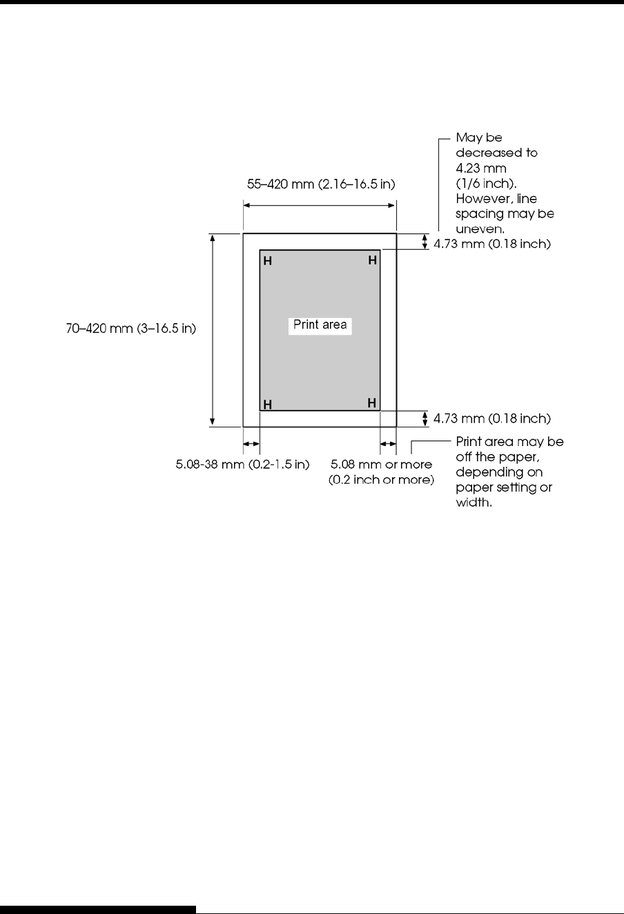
Print Area
This section illustrates the recommended print area for single sheets and
continuous forms.
Print area for single sheets
PAPER
SPECIFICATIONS
PRINTER AND PAPER SPECIFICATIONS
User's Manual B-7
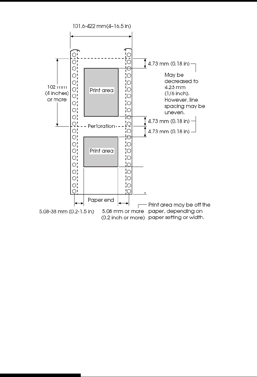
Print area for continuous forms
Approx. 101 mm (4 inches)
for front tractor feed
Approx. 157 mm (6.2 inches)
for rear tractor feed
PRINTER AND PAPER SPECIFICATIONS
B-8 User's Manual
Paper Thickness
Paper thickness is given by the weight of the paper in either grams per
square meter (g/m2) or in pounds per bond (lbs/bond). The following table
shows the allowable paper thickness for one-part paper or for each sheet of
multipart paper. The total thickness must not exceed 0.65 mm (0.026 inch).
The weight of carbonless or carbon-backed paper may vary, depending upon
the paper manufacturer. When using paper of borderline thickness, test the
paper before running a job.
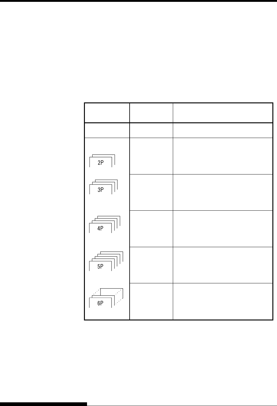
Type of Paper Number of
Parts Thickness
One-part Single 47-81 g/m2 (40-70 kg or 12-22 lb)
Carbonless
Top
Bottom
40-64 g/m2 (34-55 kg or 11-17 lb)
40-81 g/m2 (34-70 kg or 11-22 lb)
Top
Middle
Bottom
40-50 g/m2 (34-43 kg or 11-13 lb)
40-50 g/m2 (34-43 kg or 11-13 lb)
40-81 g/m2 (34-70 kg or 11-22 lb)
Top
Middle (2-3p)
Bottom
40 g/m2 (34 kg or 11 lb)
40 g/m2 (34 kg or 11 lb)
40-81 g/m2 (34-70 kg or 11-22 lb)
Top
Middle (2-4p)
Bottom
40 g/m2 (34 kg or 11 lb)
40 g/m2 (34 kg or 11 lb)
40-64 g/m2 (34-55 kg or 11-17 lb)
Top
Middle (2-5p)
Bottom
40 g/m2 (34 kg or 11 lb)
40 g/m2 (34 kg or 11 lb)
40-64 g/m2 (34-55 kg or 11-17 lb)
kg: Weight in kilograms of 1000 sheets of 788 × 1091 mm paper
(1.16 g/m2)
lb: Weight in pounds of 500 sheets of 17 × 22 inch paper (3.76 g/m2)
PRINTER AND PAPER SPECIFICATIONS
User's Manual B-9
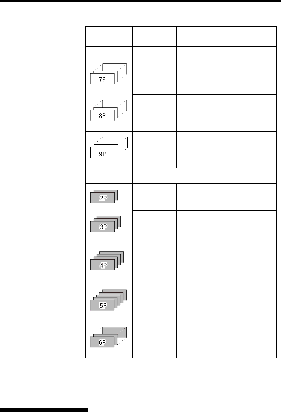
Type of Paper Number of
Parts Thickness
Carbonless
Top
Middle (2-6p)
Bottom
40 g/m2 (34 kg or 11 lb)
40 g/m2 (34 kg or 11 lb)
40-64 g/m2 (34-55 kg or 11-17 lb)
Top
Middle (2-7p)
Bottom
40 g/m2 (34 kg or 11 lb)
40 g/m2 (34 kg or 11 lb)
40-64 g/m2 (34-55 kg or 11-17 lb)
Top
Middle (2-8p)
Bottom
40 g/m2 (34 kg or 11 lb)
40 g/m2 (34 kg or 11 lb)
40-64 g/m2 (34-55 kg or 11-17 lb)
Carbon-backed Do not use in high humidity environments.
Top
Bottom
40-64 g/m2 (34-55 kg or 11-17 lb)
40-81 g/m2 (34-70 kg or 11-22 lb)
Top
Middle
Bottom
40-52 g/m2 (34-45 kg or 11-14 lb)
40-52 g/m2 (34-45 kg or 11-14 lb)
40-81 g/m2 (34-70 kg or 11-22 lb)
Top
Middle (2-3p)
Bottom
40 g/m2 (34 kg or 11 lb)
40 g/m2 (34 kg or 11 lb)
40-81 g/m2 (34-70 kg or 11-22 lb)
Top
Middle (2-4p)
Bottom
40 g/m2 (34 kg or 11 lb)
40 g/m2 (34 kg or 11 lb)
40-64 g/m2 (34-55 kg or 11-17 lb)
Top
Middle (2-5p)
Bottom
40 g/m2 (34 kg or 11 lb)
40 g/m2 (34 kg or 11 lb)
40-64 g/m2 (34-55 kg or 11-17 lb)
kg: Weight in kilograms of 1000 sheets of 788 × 1091 mm paper
(1.16 g/m2)
lb: Weight in pounds of 500 sheets of 17 × 22 inch paper (3.76 g/m2)
PRINTER AND PAPER SPECIFICATIONS
B-10 User's Manual
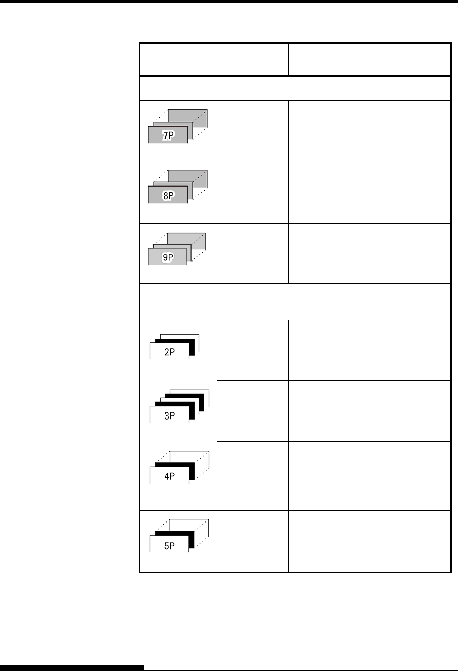
Type of Paper Number of
Parts Thickness
Carbon-backed Do not use in high humidity environments.
Top
Middle (2-6p)
Bottom
40 g/m2 (34 kg or 11 lb)
40 g/m2 (34 kg or 11 lb)
40-64 g/m2 (34-55 kg or 11-17 lb)
Top
Middle (2-7p)
Bottom
40 g/m2 (34 kg or 11 lb)
40 g/m2 (34 kg or 11 lb)
40-64 g/m2 (34-55 kg or 11-17 lb)
Top
Middle (2-8p)
Bottom
40 g/m2 (34 kg or 11 lb)
40 g/m2 (34 kg or 11 lb)
40-64 g/m2 (34-55 kg or 11-17 lb)
Carbon-
interleaved Avoid using carbon-interleaved single sheets.
Top
Carbon
Bottom
35-52 g/m2 (30-45 kg or 9-14 lb)
Counted as one sheet
35-81 g/m2 (30-70 kg or 9-22 lb)
Top
Carbon
Middle
Carbon
Bottom
35-46 g/m2 (30-40 kg or 9-12 lb)
Counted as one sheet
35-46 g/m2 (30-40 kg or 9-12 lb)
Counted as one sheet
35-64 g/m2 (30-55 kg or 9-17 lb)
Top
Carbon
Middle (3,5P)
Carbon (4,6P)
Bottom
35-46 g/m2 (30-40 kg or 9-12 lb)
Counted as one sheet
35-46 g/m2 (30-40 kg or 9-12 lb)
Counted as one sheet
35-64 g/m2 (30-55 kg or 9-17 lb)
Top
Carbon
Middle (3,5,7P)
Carbon (4,6,8P)
Bottom
35-46 g/m2 (30-40 kg or 9-12 lb)
Counted as one sheet
35-46 g/m2 (30-40 kg or 9-12 lb)
Counted as one sheet
35-64 g/m2 (30-55 kg or 9-17 lb)
kg: Weight in kilograms of 1000 sheets of 788 × 1091 mm paper
(1.16 g/m2)
lb: Weight in pounds of 500 sheets of 17 × 22 inch paper (3.76 g/m2)

User's Manual C-1
C
APPENDIX C COMMAND SETS
COMMAND SETS
This appendix describes printer commands and
their parameters.
This printer has three resident command sets:
• Fujitsu DPL24C PLUS (native command set for Fujitsu DL
series printers)
• IBM Proprinter XL24E
• Epson ESC/P2
Separate programmer s manuals are available for these emulations.
See Appendix A for order information.
Select the same emulation on the printer and in your software. If your
software emulations include DPL24C PLUS, select DPL24C PLUS for
optimum performance.

COMMAND SETS (DPL24CPLUS)
C-2 User's Manual
This section describes the printer commands for the DPL24C PLUS
command set which is the native command set of this printer. See the
Programmer’s Manual (DPL24C PLUS) for detailed information on
using these commands.
Function Command
Print Mode Control
Double-strike (bold) printing on
Double-strike (bold) printing off
Emphasized (shadow) printing on
Emphasized (shadow) printing off
Italic printing on
Italic printing off
Select character style and screening
n1= 0:Normal
1:Outline
2:Shaded
3:Outline and shaded
4:Thin outline
5:Thin shaded
6:Thin outline and shaded
n2= 0:Transparent
1:Light dot matrix
2:Heavy dot matrix
3:Vertical bars
4:Horizontal bars
5:Slants
6:Back slants
7:Lattice
One-line double width characters on
One-line double width characters off
Double width characters on/off
(on: n = 1, off: n = 0)
ESC G
ESC H
ESC E
ESC F
ESC 4
ESC 5
ESC e S (n1) (n2)
SO or ESC SO
DC 4
ESC W (n)
FUJITSU DPL24C
PLUS
COMMAND SETS
User's Manual C-3
Function Command
Double-height characters on/off
(on: n = 1, off: n = 0)
This command does not adjust the line
spacing.
Multiwidth and height printing
n = 0: Not adjusted
1: Character pitch multiplied
2: Line spacing multiplied
3: Character pitch and line spacing
multiplied
h1: Tens digit of horizontal multiple
h2: Units digit of horizontal multiple
v1: Tens digit of vertical multiple
v2: Units digit of vertical multiple
(0 < h1h2 or v1v2 < 11)
Condensed characters on
Condensed characters off
Subscript or superscript printing on
(subscript: n = 1, superscript: n = 0)
Subscript and superscript printing off
Select underline type
n = 0:Single line
1:Bold single line
2:Extremely bold single line
3:Double line
4:Bold double line
5:Extremely bold double line
Underline on/off
(on: n=1, off: n=0)
Overline on/off
(on: n=1, off: n=0)
ESC V (n)
ESC u (n) (h1) (h2)
(v1) (v2)
SI or ESC SI
DC2
ESC S (n)
ESC T
ESC e U (n)
ESC- (n)
ESC e o (n)
COMMAND SETS (DPL24CPLUS)
C-4 User's Manual
Function Command
Select printing style
This command allows you to combine
various printing styles. The value of n is
the sum of the values of the styles you
want to combine.
n= 0:Pica pitch
1:Elite pitch
4:Condensed
8:Shadow
16:Bold
32:Double width
64:Proportional
Select image overlay type
This command allows you to overlay a
pattern on characters.
n= 1:Light dot matrix
2:Heavy dot matrix
3:Vertical bars
4:Horizontal bars
5:Slants
6:Back slants
7:Lattice
Image overlay printing on/off
(on:n=1, off: n=0)
ESC ! (n)
ESC e I (n)
ESC e L (n)
Horizontal Control
Space
Backspace
Carriage return
Elite pitch (12 cpi)
Pica pitch (10 cpi)
Proportionally spaced characters on/off
(on:n=1, off: n=0)
Set character pitch to (n-1)/120 inch
(1 < n < 127)
Set character pitch to n/180 inch
(0 < n < 255)
SP
BS
CR
ESC M
ESC P
ESC p (n)
ESC US (n)
ESC h (n)
COMMAND SETS
User's Manual C-5
Function Command
Set character offset to n/120 inch
Cancelled by CR or ESC x.
(0 < n < 63) (64 < n < 127)
Set character pitch to n/360 inch
(0 < n1 n2 n3 < 999)
n1, n2, and n3 are the hundreds, tens, and
units digits.
ESC DC1 (n)
ESC e H
(n1) (n2) (n3)
Vertical Control
Line feed
Reverse line feed
Form feed
Advance paper n/180 inch (0 < n < 255)
Reverse paper n/180 inch (0 < n < 255)
Advance paper n/360 inch
(0 < n1 n2 n3 < 999)
n1, n2, and n3 are the hundreds, tens, and
units digits.
Reverse paper n/360 inch
(0 < n1 n2 n3 < 999)
n1, n2, and n3 are the hundreds, tens, and
units digits.
Set line spacing to 1/8 inch (8 lpi)
Set line spacing to n/180 inch
(0 < n < 255)
Set line spacing to 7/60 inch
Set line spacing to n/60 inch
(0 < n < 127)
Set line spacing to 1/6 inch (6 lpi) or to the value
set with the ESC A command.
The preset line spacing command is
ESC A (n).
Set line spacing to n/360 inch
(0 < n1 n2 n3 < 999)
n1, n2, and n3 are the hundreds, tens, and
units digits.
Set line spacing to n/360 inch
(1 < n < 255)
LF
LF ESC
FF
ESC J (n)
ESC j (n)
ESC e J
(n1) (n2) (n3)
ESC e j
(n1) (n2) (n3)
ESC 0
ESC 3 (n)
ESC 1
ESC A (n)
ESC 2
ESC e V
(n1) (n2) (n3)
FS 3 (n)
COMMAND SETS (DPL24CPLUS)
C-6 User's Manual
Function Command
Tabulation
Horizontal tab execution
Set horizontal tabs
The values of n1 to nk in this command
are the ASCII values of the print
columns (at the current character width)
at which tabs are to be set.
(1 < n < 255) (1 < k < 255)
Move to print column n (1 < n < 255)
Move dot column n/360 inch
(n = n1 + n2 × 256)
The value below is for 136-column printers.
(0 < n1 < 255) (0 < n2 < 19)
(0 < n2 × 256 + n1 < 4895)
Horizontal relative move by n/360 inch
(-999 < n1 n2 n3 < +999)
n1, n2, and n3 are the hundreds, tens, and
units digits of the distance.s is a plus
or minus ( + or -) sign.
Vertical tab execution
Set vertical tabs
The values of n1 to nk in this command
are the ASCII values of the lines (at the
current line spacing) at which tabs are
to be set.
(1 < n < 255) (1 < k < 64)
Move to line n (1 < n < 255)
HT
ESC D (n1) ... (nk)
NUL
ESC HT (n)
ESC $ (n1) (n2)
ESC e R (s)
(n1) (n2) (n3)
VT
ESC B (n1) ... (nk)
NUL
ESC VT (n)
Page Formatting
Set right margin (0 < n < 255)
Set left margin (0 < n< 255)
Set perforation skip by n lines
(1 < n < 127)
Perforation skip off
Set page length to n lines
(1 < n < 127)
ESC Q (n)
ESC 1 (n)
ESC N (n)
ESC O
ESC C (n) or
ESC FF (n)

COMMAND SETS
User's Manual C-7
Function Command
Set page length to n inches
(1 < n < 22)
Set page length to n/360 inch
(n = n1 × 256 + n2)
(0 < n1 n2 < 255)
(1 < n1 < 256 + n2 < 7920)
ESC C NUL (n) or
ESC e C NUL (n) or
ESC FF NUL (n)
ESC e f (n1) (n2)
Character Set Control
Select character set 1
Appendix E gives the character sets
Select character set 2
Appendix E gives the character sets.
Select international character set
n = 0:USA
1:France
2:Germany
3:United Kingdom
4:Denmark 1/Norway
5:Sweden/Finland
6:Italy
7:Spain
8:Denmark 2
Clear print buffer
Select printer
Deselect printer (ignore input)
Force most significant bit to 1
Force most significant bit to 0
Cancel control over most significant bit
ESC 7
ESC 6
ESC R (n)
CAN
DC1
DC3
ESC >
ESC =
ESC #
COMMAND SETS (DPL24CPLUS)
C-8 User's Manual
Function Command
Select code table
n = 0:Code page 437
1:Code page 850
2:Code page 860
3:Code page 863
4:Code page 865
5:ISO 8859-1/ECMA 94
Select extended character by character
number
(0 < n1 n2 n3 < 664)
n1, n2, and n3 are the hundreds, tens, and
units digits.
ESC e C (n)
ESC e E
(n1) (n2) (n3)
Word Processing
Line justification on
Automatically center printing
Reset word processing features
ESC m
ESC c
ESC x
Font Selection and Downloading
Select font m with source and style set by n
• m (bits 0 and 1: Font device selection)
Bit 1 Bit 0 Selection of font
0
0
1
0
1
0
Resident font
Downloaded font
Resident font
• m (bits 2 and 3: Print quality specification
Bit 3 Bit 2 Print quality
0
0
1
1
0
1
0
1
Original quality of font
Letter quality (360 dpi)
Correspondence
quality (180 dpi)
Draft quality (120 dpi)
ESC % (m) (n)
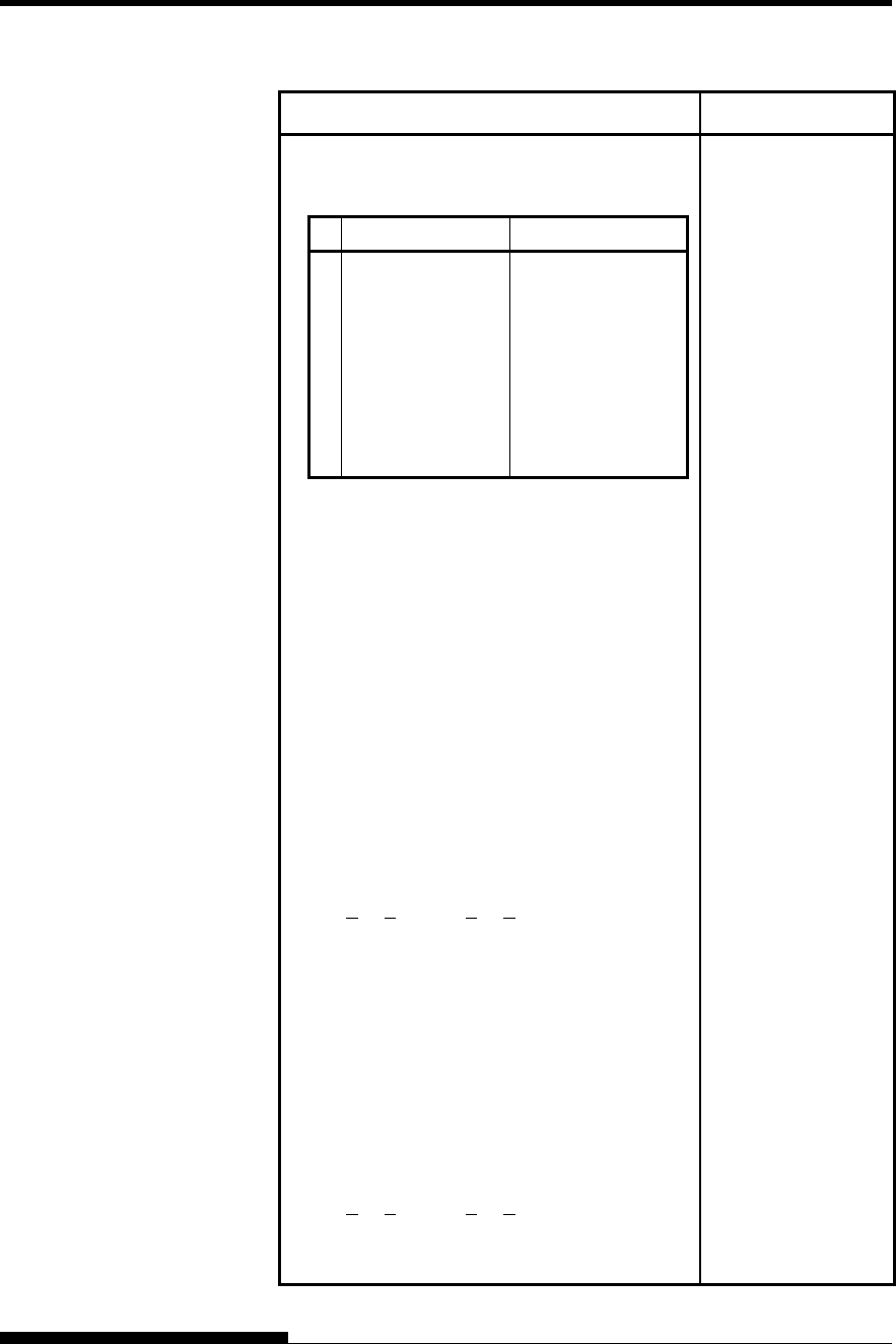
COMMAND SETS
User's Manual C-9
Function Command
• n (bit 0 to 2: Specification of font number)
(1) Resident fonts
n m (bit 1, 0) = 0, 0 m (bit 1, 0) = 1, 0
0
1
2
3
4
5
6
7
Courier 10
Prestige elite 12
Draft
Compressed
Boldface PS
Pica 10
Correspondence
High-speed draft
OCR-B
OCR-A
(2) Downloaded fonts
n = 0: Downloaded font 0
1: Downloaded font 1
Select print quality (font attributes)
n = 0:Letter (360 × 180 dpi)
1:Correspondence (180 × 180 dpi)
2:Draft (120 × 180 dpi)
3:High-speed Draft (90 × 180 dpi)
Select spacing mode (font attributes)
n = 0:Fixed pitch font
1:Proportional spacing font
Select character pitch (n/360 inch, font
attributes)
(0 < n1 < 255) (1 < n2 < 255)
(n = n1 × 256 + n2)
Ex.n = 36: 10 pitch
30: 12 pitch
24: 15 pitch
21: 17 pitch
Condense/enlarge vertically (font attributes)
n = 1:Executed
0:Not executed
Select point size (n/1200 inch, font attributes)
(0 < n1 < 255) (0 < n2 < 255)
(n = n1 × 256 + n2)
Ex. n =166: 10 point
ESC e q (n)
ESC e s (n)
ESC e p (n1) (n2)
ESC e A (n)
ESC e v (n1) (n2)
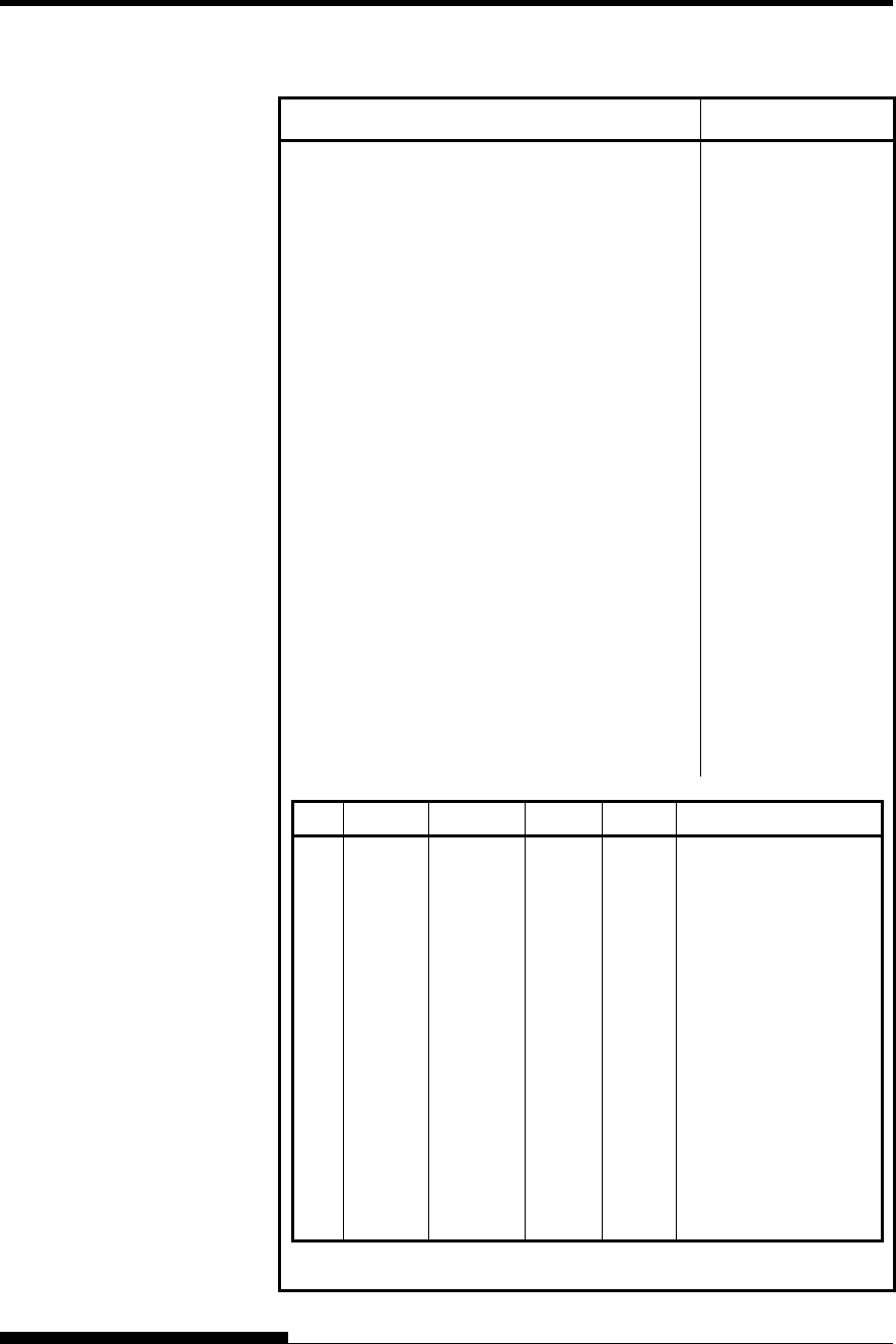
COMMAND SETS (DPL24CPLUS)
C-10 User's Manual
Function Command
Select character style (font attributes)
n = 0:Upright
1:Italic
Select stroke weight (font attributes)
n = 249:-7 (reserved)
251:-5 (reserved)
253:-3 (light)
0:0 (medium)
3:3 (bold)
5:5 (black)
7:7 (ultrablack)
Select typeface (font attributes)
n = 1:Pica
3:Courier (bitmap)
4:Nimbus Sans
5:Timeless
6:Gothic
8:Prestige
23:Boldface
130:OCR-A
131:OCR-B
134:Courier (scalable)
Select font by I.D. (font attributes)
ESC e i (n)
ESC e w (n)
ESC e t (n)
ESC e F (n)
n Quality Spacing Pitch Point Typeface
1
2
3
4
9
10
32
34
128
129
130
132
133
134
140
141
142
LQ
LQ
LQ
LQ
LQ
LQ
LQ
LQ
LQ
LQ
LQ
LQ
LQ
LQ
LQ
LQ
LQ
Fixed
Fixed
PS
Fixed
Fixed
Fixed
Fixed
Fixed
PS
PS
PS
PS
PS
PS
Fixed
Fixed
Fixed
10 cpi
12 cpi
-
10 cpi
10 cpi
10 cpi
10 cpi
12 cpi
-
-
-
-
-
-
10 cpi
10 cpi
10 cpi
12 pt
10 pt
12 pt
12 pt
12 pt
12 pt
12 pt
11pt
10 pt
10 pt
10 pt
10 pt
10 pt
10 pt
10 pt
10 pt
Courier (bitmap)
Prestige
Boldface
Pica
OCR-A
OCR-B
Courier (bitmap)
Gothic
Timeless
Timeless Italic
Timeless Bold
Nimbus Sans ®
Nimbus Sans ® Italic
Nimbus Sans ® Bold
Courier (scalable)
Courier Bold (scalable)
Courier Italic (scalable)
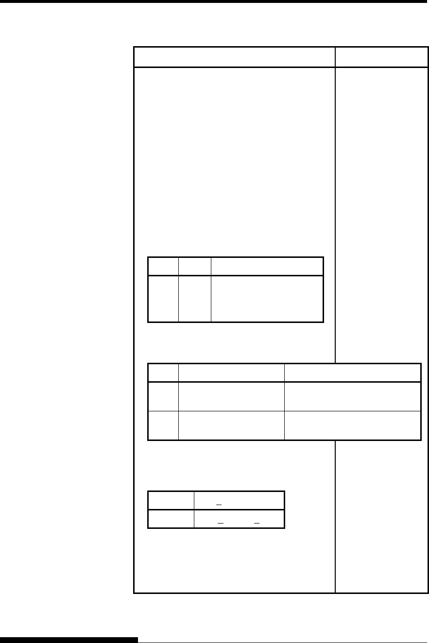
COMMAND SETS
User's Manual C-11
Function Command
Copy resident font to download area
m = 0:Courier 10
1:Prestige Elite 12
2:Draft
3:Compressed
4:Boldface PS
5:Pica 10
6:Correspondence
7:High-speed Draft
n = 0:Downloaded font 0
1:Downloaded font 1
Create download font
• m (bits 4 and 5: Specifies the quality of
characters to be registered)
Bit 5 Bit 4 Font quality selection
0
1
1
1
0
1
Letter (360 dpi)
Correspondence (180 dpi)
Draft (120 dpi)
• m (bit 0: Specifies external font number
to be registered)
ESC : NUL (m) (n)
ESC & (m) (Cs)
(Ce) (data)
Bit 0 Font number selection Remarks
0 Downloaded font 0 At power on, resident font 0 is
automatically downloaded.
1 Downloaded font 1 At power on, resident font 1 is
automatically downloaded.
• m (bits 1, 2, 3, 6, 7) Not used (don’t care)
• Cs (Download start character, ASCII code)
• Ce (Download end character, ASCII code)
Decimal 00 < Cs, Ce < 255
Hex 00 < Cs, Ce < FF
Precaution: Ce ≥ Cs
• data (More than one byte of data
containing bit map data)
(Reserved)
ESC e D (data);
COMMAND SETS (DPL24CPLUS)
C-12 User's Manual
Function Command
Bit Image Graphics
Graphics type m graphics
Graphics type m graphics
Single-density graphics
Double-density graphics
High-speed double-density graphics
Quadruple-density graphics
360 dot per inch 24-pin graphics
ESC * (m)
(n1) (n2) (data)
ESC e b (m)
(n1) (n2) (data) or
ESC e B (m)
(n1) (n2) (data)
ESC K (n1) (n2) (data)
ESC L (n1) (n2) (data)
ESC Y (n1) (n2) (data)
ESC Z (n1) (n2) (data)
FS Z (n1) (n2) (data)
Cut Sheet Feeder Control
Feed a sheet from bin 1
Feed a sheet from bin 2
Feed a sheet from bin 3
Eject a page from the printer
Select bin 1 for following pages
Select bin 2 for following pages
Select bin 3 for following pages
ESC EM 1
ESC EM 2
ESC EM E
ESC EM R
/ / 1 / /
/ / 2 / /
/ / E / /
Initialize Printer
Reset printer
Reset printer
Initialize printer
ESC @
ESC CR P
ESC SUB I
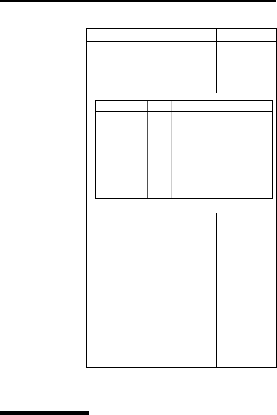
COMMAND SETS
User's Manual C-13
Function Command
Bar Code Printing
Print bar code
b: Total number of parameters
R: (fixed)
c: Type of bar code
ESC DC4 (b) R
(c) (w) (h) (a)
(ch1) ... (chn)
ASCII Decimal Hex Type
1
2
3
4
5
6
7
A
B
a
49
50
51
52
53
54
55
65
66
97
31
32
33
34
35
36
37
41
42
61
Codabar (nw-7)
EAN 13
EAN 8
Code 3 of 9
Industrial 2 of 5
Interleaved 2 of 5
Matrix 2 of 5
UPC type A
Code 128
UPC type A with checkdigit printing
w: Width of narrow bar in 1/1440-inch
units
h: Height of bar code
a: Defines check characters and OCR
characters
ch1 ... chn: Bar code characters
NOTE
When EAN13, UPC type A, or UPC type A
with checkdigit printing is selected as the type
of barcode, printing the barcode from the left
(from the first dot) will cause the omission of
a flag character that should by printed on the
lower left or middle left of it. Therefore,
when printing these types of barcode, leave
two or more spaces open from the left.
See the next page for details of the Bar Code
Command.
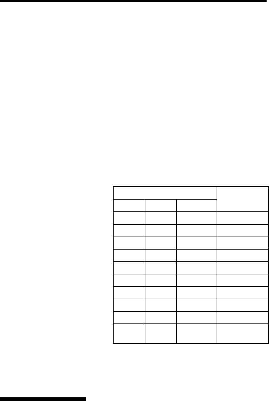
COMMAND SETS (DPL24CPLUS)
C-14 User's Manual
Bar Code Printing Control
ASCII : ESC + DC4 + b + R + c + w + a + ch1 … + chn
Hexadecimal : 1B + 14 + b + 52 + c + w + a + ch1 … + chn
Decimal : 27 + 20 + b + 82 + c + w + a + ch1 … + chn
(1) Function
(a) Instructs the printing of bar codes according to the different
specifications of this command.
(2) Valid range of parameters
(a) b (Specification of number of bytes) = Actual number of data +
6
(b) R (Fixed)
ASCII : R
Hexadecimal : 82
Decimal : 52
(c) C (Specifies the type of bar code to be printed. No printing is
done if any value other than the following is specified.)
C
ASCII Decimal Hexadecimal Type of bar code
1 49 31 Codabar (nw-7)
2 50 32 EAN 13
3 51 33 EAN 8
4 52 34 Code 3 of 9
5 53 35 Industrial 2 of 5
6 54 36 Interleaved 2 of 5
7 55 37 Matrix 2 of 5
A 65 41 UPC type A
B 66 42 CODE 128
a 97 61
UPC type A with
check character
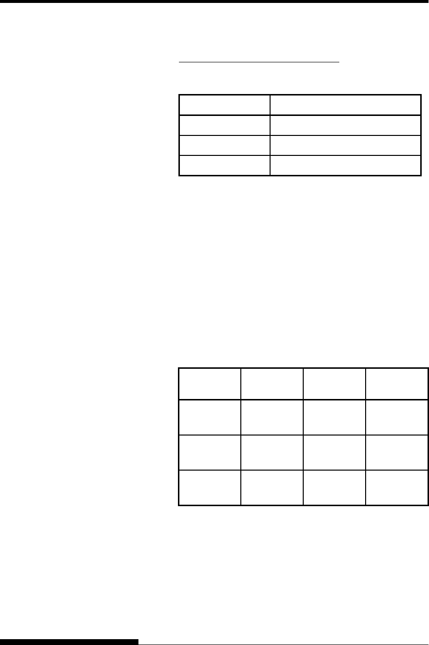
COMMAND SETS
User's Manual C-15
(d) w (Specify the width of the narrow bar of the bar code to be
printed in units of 1/1440.)
Specify the “Logical value” to be printed (in units of 1/1440).
Actual printing: The printer prints with the width given in the
following table in units of 1/180 inches.
w Width of narrow bar
1 ~ 19 2 Dots (2/180 inches)
20 ~ 27 3 Dots (3/180 inches)
28 ~ 4 Dots (4/180 inches)
(e) h (Specify the height of the bar code to be printed in units of
1/1440 taking the narrow bar width as the reference.)
Height of bar code = (parameter w) × (parameter h) [in units
of 1/1440]
Height of bar code ≤ 11 Inches
Actual printing: The printing is done with the following initial
values if the bar code height is less than or
equal to 24 dots taking 1 dot equal to 1/180
inches of the printing unit of the printer.
The following values are the standard heights for the respective
bar code standards. Enter the value so that the height is ≤
23/180 if the standard is correct.
Narrow bar
width EAN
13/UCP-A EAN 8 Others
2 Dots
(16/1440)
162 Dots
(1296/1440)
130 Dots
(1040/1040)
108 Dots
(864/1440)
3 Dots
(24/1440)
234 Dots
(1872/1440)
187 Dots
(1496/1040)
135 Dots
(1080/1440)
4 Dots
(32/1440)
312 Dots
(2496/1440)
249 Dots
(1992/1040)
162 Dots
(1296/1440)
Figures in parentheses ( ) are values converted to units of
1/1440.
..
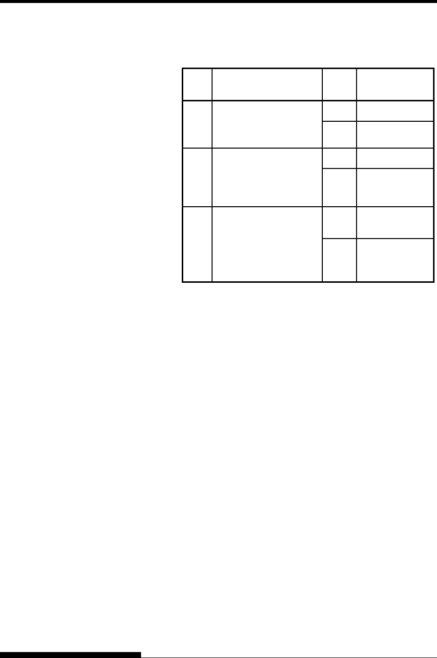
COMMAND SETS (DPL24CPLUS)
C-16 User's Manual
(f) a (Bits 2~0: Specifications related to the check and OCR
characters.)
Bit Content of specification value Content of
setting
0 Added
0
Check character
Additional specification
* 1 1 Not added
0 Printed
1
Specification of OCR
character printing
(OCR-B is taken as the
standard) 1 Not printed
0 To the left of the
bar code
2
Printing position of
EAN, UPC flag
character 1
To the bottom
left of the bar
code
*1: The specification becomes invalid for the following bar
codes:
Codabar … Always the non-additional code is set.
EAN, UPC … Always the additional code is set.
*2: The flag character is printed when Bit 1 = 0.
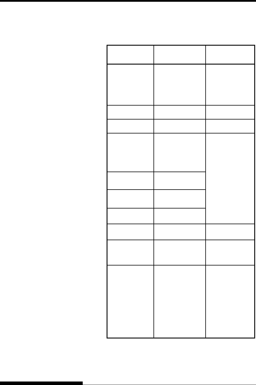
COMMAND SETS
User's Manual C-17
(g) (ch1) … (chn)
The data and the printable character set are listed below.
Type of bar
code Usable character
set Data count
Codabar Numerals: 0 ~ 9
Symbols; + -, $/:
Start, Stop:
A,a,B,b,C,c,D,d,
T,t,N,n,*,E,e
1 ≤ n ≤ 64
Includes Start and
Stop
EAN 13 Numerals: 0 ~ 9 Fixed at n=12
EAN 8 Numerals: 0 ~ 9 Fixed at n=7
Code 3 of 9 Numerals: 0 ~ 9
Alphabets: A ~ Z:
Symbols:
+-,$/%SPACE
Start, Stop:*
Industrial 2 of 5 Numerals: 0 ~ 9
Interleaved
2 of 5 Numerals: 0 ~ 9
Matrix 2 of 5 Numerals: 0 ~ 9
Check character
Additional code
1 ≤ n ≤ 63
Check character
Non-additional
code
1 ≤ n ≤ 64
UPC Type A Numerals: 0 ~ 9 Fixed at n=11
UPC Type A
with check
character
Numerals: 0 ~ 9 Fixed at n=11
Code 128
ASCII Code
Start code: A, B, C
Code set C: 0 ~ 9
Check character
Additional code
1 ≤ n ≤ 63
Check character
Non-additional
code
1 ≤ n ≤ 64
Code set C: 2n
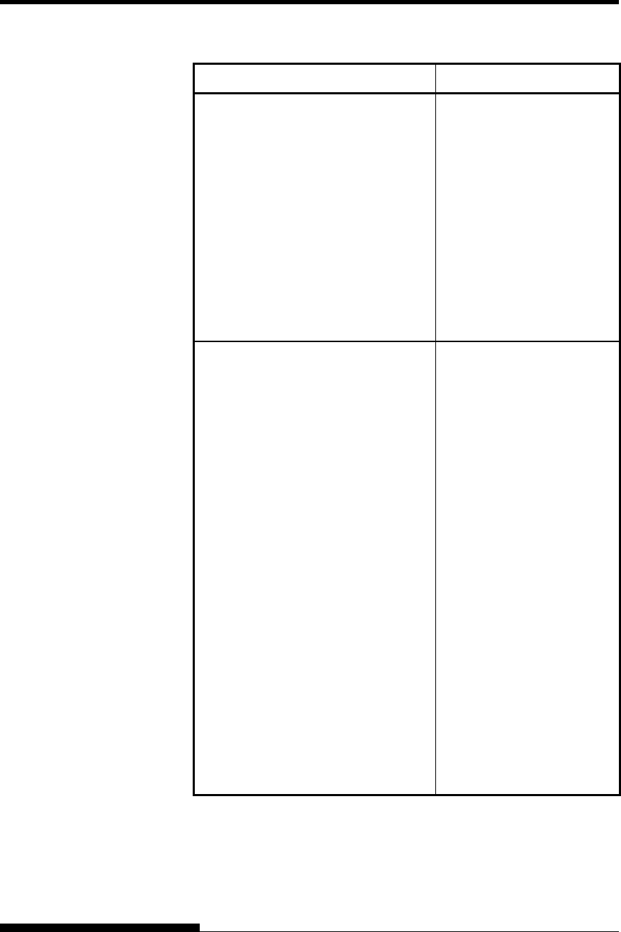
COMMAND SETS (DPL24CPLUS)
C-18 User's Manual
Function Command
Print Option Control
Friction feed selection
Rear tractor feed selection
Front tractor feed selection
Cut sheet feed selection
Host controlled paper path control
n = “F” :Friction
“T” :Rear Tractor
“M” : Front Tractor
Automatic paper thickness control
/ / F / /
/ / T / /
/ / M / /
/ / S / /
ESC e T (n)
ESC e P (n1) (n2) (n3) (n4)
Miscellaneous
Sound bell
Enable paper-out sensor
Ignore paper-out sensor
Typewriter mode on/off
(on:n=1, off: n=0)
Move print head to home position
Unidirectional printing on/off
(on:n=1, off: n=0)
Select CR code definition
n = 0:CR = CR only
1:CR = CR + LF
Select LF code definition
n = 0:LF = LF only
1:LF = LF + CR
Enter online setup mode
Move print head (unit: 1/180 inch)
(0 < n1 < 255) (0 < n2 < 255)
BEL
ESC 9
ESC 8
ESC i (n)
ESC <
ESC U (n)
ESC e r (n)
ESC e l (n)
ESC e ONLINE (data)
ESC e h (n1) (n2)
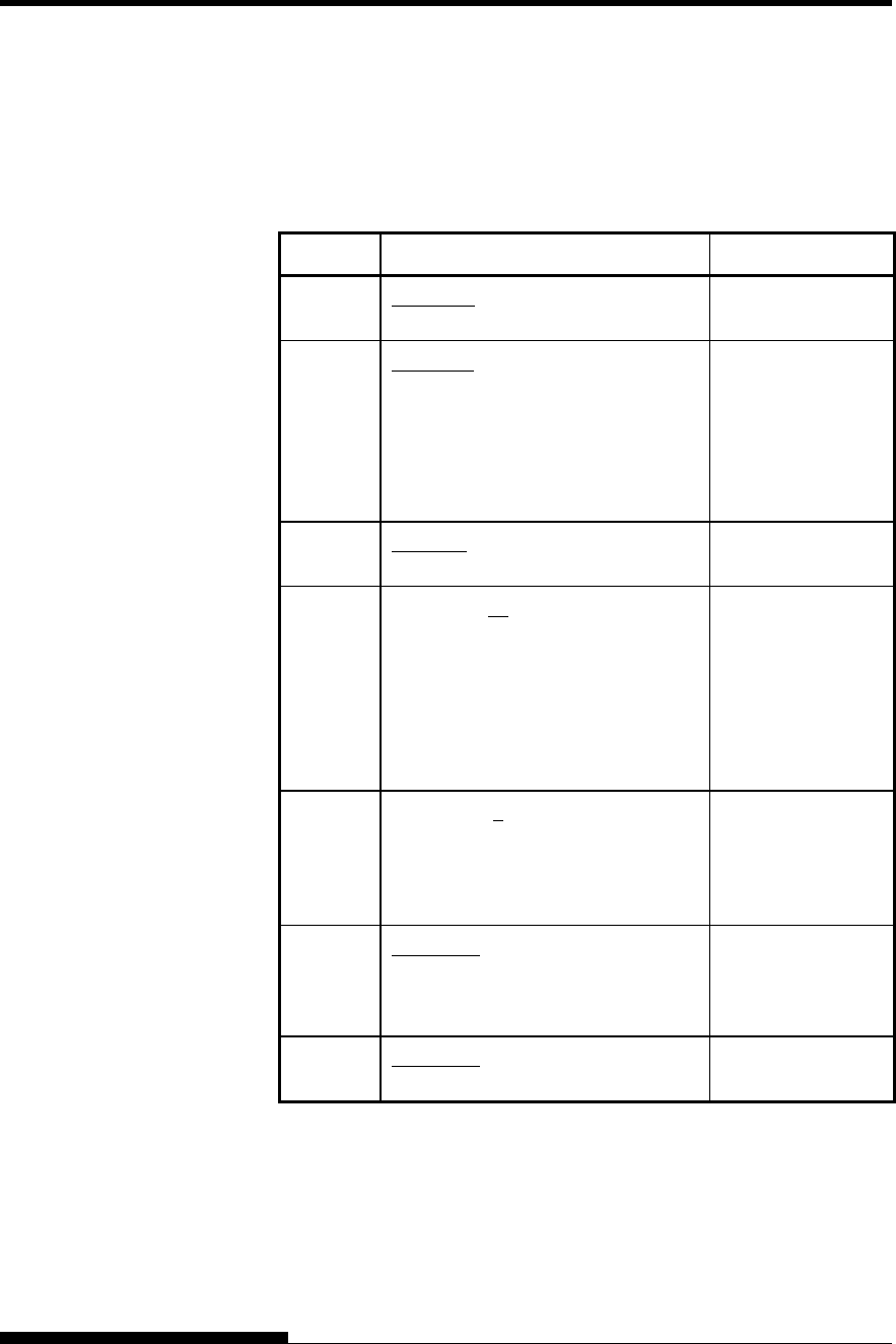
COMMAND SETS
User's Manual C-19
Factory Default Settings
The following table describes the printer commands used to control
options of the items that can be selected in printer setup mode. Command
parameters are omitted
Item Selectable options in setup mode Command
Emulate DPL24C+, XL24E, ESC/P2 Controllable in
online setup mode
Font COUR 10, PRSTG 12, COMPRSD,
BOLDFCE, PICA 10, CORRESP,
COUR-N, COUR-B, COUR-I,
TIMLS-N, TIMLS-B, TIMLS-I,
N.SAN-N, N.SAN-B, N.SAN-I.
OCR-B, OCR-A, DOWNLD 0,
DOWNLD 1
ESC e t
ESC e F
ESC %
Quality LETTER, REPORT, DRAFT, HI-
DRFT
ESC e q
Pitch 2.5, 3, 5, 6, 10, 12, 15, 17, 18, 20 CPI
or PROP SP
ESC e p
ESC e H
ESC h
ESC US
ESC M
ESC P
ESC p ESC i
ESC e s
Line
space
1, 2, 3, 4, 5, 6, 7, 8, LPI ESC e V
ESC 0 ESC 1
ESC 2
ESC 3
ESC A
Character
width
NORMAL, 2 TIMES, 4 TIMES ESC W
SO or ESC SO
(DC4) ESC u
ESC !
Character
height
NORMAL, 2 TIMES, 4 TIMES ESC V
ESC u
Underline: Factory default
( ): Cancel command
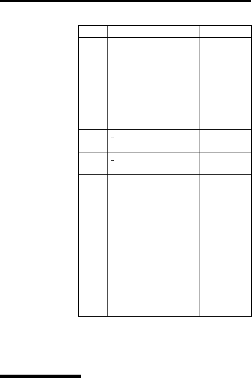
COMMAND SETS (DPL24CPLUS)
C-20 User's Manual
Item Selectable options in setup mode Command
Attributes NONE, ITALICS, CONDNSD,
SHADOW, BOLD
ESC 4 (ESC 5)
SI or ESC SI
(DC2)
ESC E (ESC F)
ESC G (ESC H)
ESC e i ESC !
Page
length
3.0, 3.5, 4.0, 5.0, 5.5, 6.0, 7.0, 8.0,
8.5, 11.0, 11.6, 12.0, 14.0, 18.0 IN
ESC C NUL
ESC e C NUL
ESC FF NUL
ESC C
ESC e C
ESC FF
Left end 1 , 2, 3, ... , 41 COLM Controllable in
online setup mode
Top
margin
1 , 2, 3, ... , 10 LINE Controllable in
online setup mode
USA, UK, GERMAN, FRENCH,
ITALIAN, SPANISH, SWEDISH,
FINNISH, DANISH1, DANISH2,
NORWEGN, PAGE437, PAGE850,
PAGE860, PAGE863, PAGE865
ISO8859, ECMA94
ESC R
ESC e C
Language
PG852, PG852-T, PG855, PG866,
HUNGARY, HUNG-T, SOLV,
SOLV-T, POLISH, POLSH-T,
MAZOWIA, MAZOW-T, LATIN7,
LATIN2, LATN2-T, KAMENIC,
KAMEN-T, TURKY, TURKY-T,
CYRILIC, IBM437, IBM851,
ELOT928, PG-DHN, LATIN-P,
ISO-LTN, LITHUA1, LITHUA2,
MIK, MACEDON, ABG, ABY, PG-
MAC, ELOT927, DEC-GR, GREEK
11, PG862, HBR-OLD, HBR-DEC,
ISO-TUK, RUSCII, LATIN-9 ,
WCP1250, WCP1251, WCP1252
Uncontrollable by
commands but
controllable in
online setup mode
Underline: Factory default
( ): Cancel command
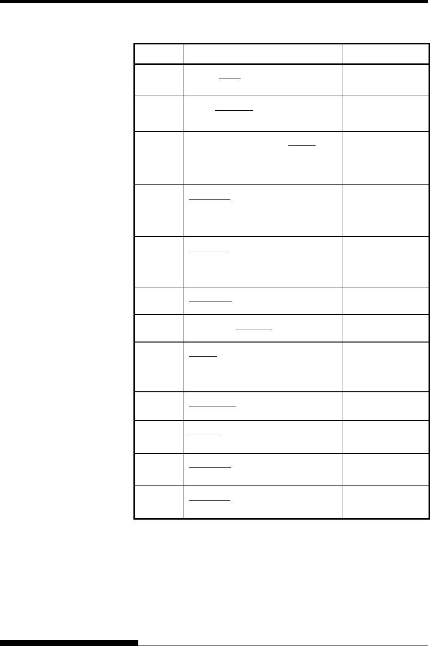
COMMAND SETS
User's Manual C-21
Item Selectable options in setup mode Command
Character
set
SET 1, SET2 ESC7 ESC6
Perfora-
tion skip
SKIP, NO-SKIP ESC N (ESC O)
Paper
width
8.0 IN, 11.0 IN, 11.4 IN, 13.6IN, (8.0
IN is default for 80-column printer,
and 13.6 IN is default for 136-
column printer)
Controllable in
online setup mode
Zero font NO-SLSH, SLASH Controllable in
online setup mode
DC3 ENABLE, DISABLE Controllable in
online setup mode
CR code CR-ONLY, CR & LF ESC e r
LF code LF-ONLY, LF & CR ESC e l
Right end
wrap
WRAP, OVR-PRT Controllable in
online setup mode
Paper-out CNTONLY, DETECT, IGNORE ESC 9 (ESC 8)
Print
direction
BI-DIR, UNI-DIR ESC U
Print
mode
NORMAL, QUIET Controllable in
online setup mode
High
Impact
DISABLE, ENABLE Controllable in
online setup mode
Underline: Factory default
( ): Cancel command
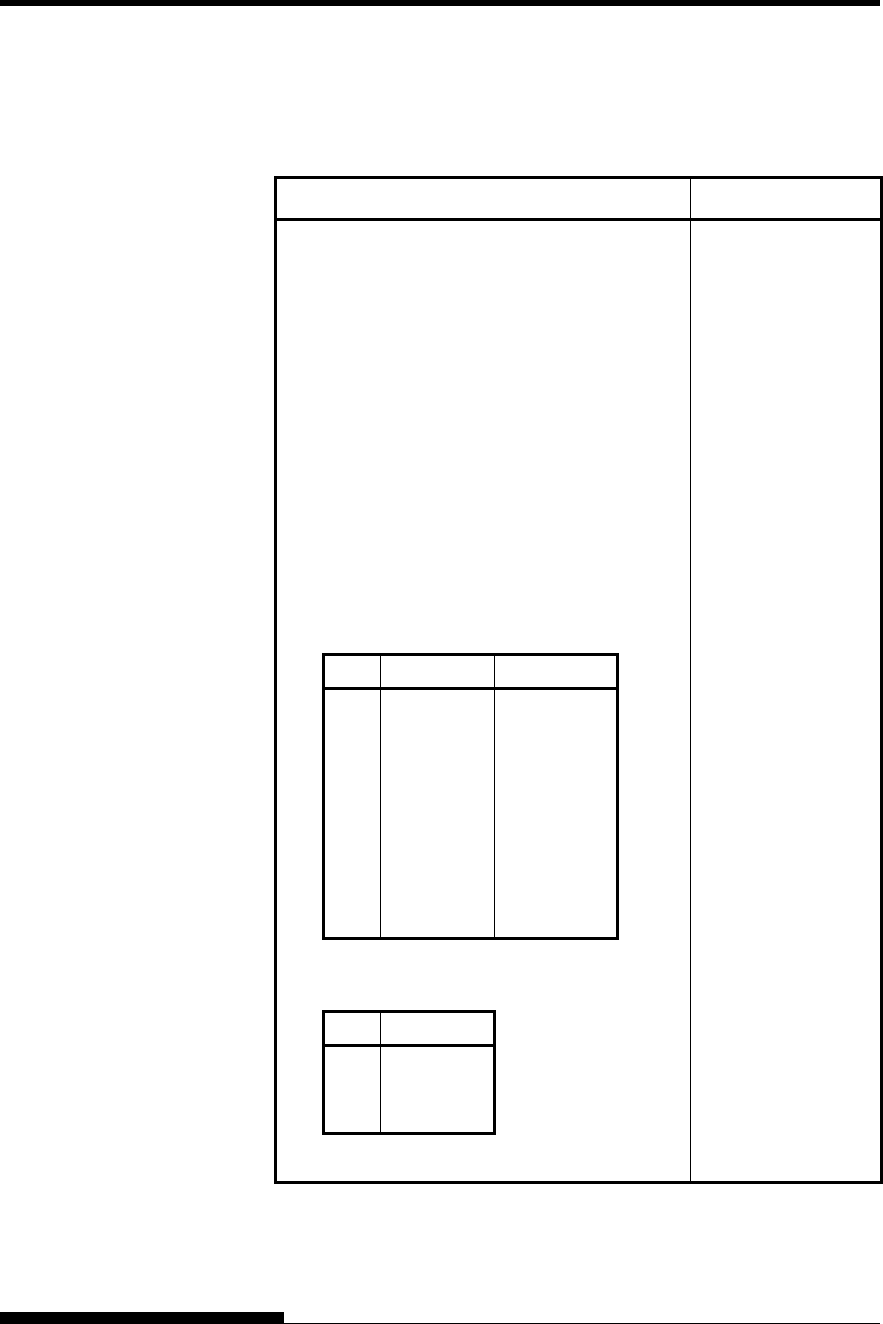
COMMAND SETS (IBM XL24E)
C-22 User's Manual
This section describes the printer commands for the IBM Proprinter
XL24E emulation. Asterisks in the “Function” column indicate extended
commands that are not supported by the original printer.
Function Command
Print Mode Control
Double-strike (bold) printing on
Double-strike (bold) printing off
Emphasized (shadow) printing on
Emphasized (shadow) printing off
One-line double-width characters on
One-line double-width characters off
Double-width characters on/off
(on: n = 1, off: n = 0)
Double-height/double-width characters
n1 = 4, n2 = 0, m1 = 0, m2 = 0
m3 controls character height and line spacing:
m3 Height Spacing
0
1
2
16
17
18
32
33
34
Unchanged
Normal
Double
Unchanged
Normal
Double
Unchanged
Normal
Double
Unchanged
Unchanged
Unchanged
Single
Single
Single
Double
Double
Double
m4 controls character width:
m3 Height
0
1
2
Unchanged
Normal
Double
ESC G
ESC H
ESC E
ESC F
SO or ESC SO
DC4
ESC W (n)
ESC [ @ (n1)(n2)
(m1) ... (m4)
IBM PROPRINTER
XL24E EMULATION
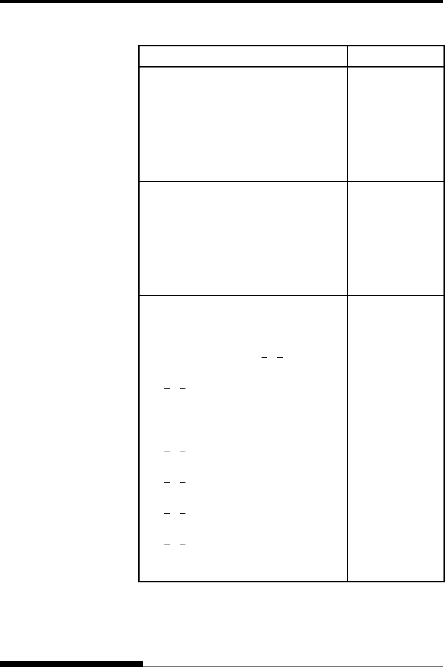
COMMAND SETS
User's Manual C-23
Function Command
Condensed characters on
Condensed and elite characters off
Subscript or superscript printing on
(subscript: n = 1, superscript: n = 0)
Subscript and superscript printing off
Underline on/off (on: n = 1, off: n = 0)
Overline on/off (on: n = 1, off: n = 0)
SI or ESC SI
DC2
ESC S (n)
ESC T
ESC - (n)
ESC_(n)
Horizontal Control
Space
Backspace
Carriage return
Elite characters on
Proportionally spaced characters on/off
(on:n= 1, off: n= 0)
SP
BS
CR
ESC:
ESC P (n)
Vertical Control
Line feed
Form feed
Advance papern/216 inch (1 < n < 255)
Advance papern/180 inch (in AG mode)
(1 < n < 255)
Set line spacing to 1/8 lines
Set line spacing to 7/72 inch
Set line spacing to n/216 inch
(0 < n < 255)
Set line spacing to n/180 inch (in AG mode)
(0 < n < 255)
Preset line spacing to n/72 inch
(1 < n < 255)
Preset line spacing to n/60 inch (in AG mode)
(1 < n < 255)
Set line spacing to 1/6 inch or to the value
preset by line spacing command ESC A (n)
LF
FF
ESC J (n)
ESC J (n)
ESC 0
ESC 1
ESC 3 (n)
ESC 3 (n)
ESC A (n)
ESC A (n)
ESC 2
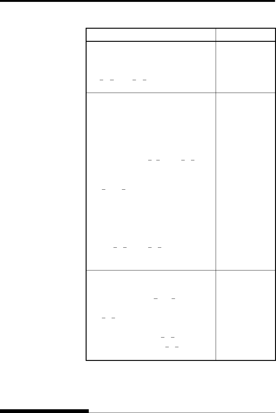
COMMAND SETS (IBM XL24E)
C-24 User's Manual
Function Command
Change graphics line spacing base to
1/216 or 1/180 inch (for ESC J and ESC 3)
m1 = 4, m2 = 0
0 < t1 < 255, 0 < t2 < 255, t3 = 0
t4 = 180 or 216
ESC [ \ (m1) (m2)
(t1) ... (t4)
Tabulation
Horizontal tab execution
Set horizontal tabs
The values of n1 to nk in this command
are the ASCII values of the print columns
(at the current character width) at which
tabs are to be set. (1 < n< 255) (1 < k < 28)
Clear all horizontal tabs
Move print position right by n/120 inch
(0 < n1, n2 < 255) (n = n1 + n2 × 256)
Vertical tab execution
Set vertical tabs
The values of n1 to nk in this command
are the ASCII values of the lines (at the
current line spacing) at which tabs are to be
set. (1 < n < 255) (1 < k < 64)
Clear all vertical tabs
Reset tabs to default values
HT
ESC D (n1)...
(nk) NUL
ESC D NUL
ESC d (n1)(n2)
VT
ESC B (n1)...
(nk) NUL
ESC B NUL
ESC R
Page Formatting
Set left margin at column n and right
margin at column m (0 < n, m < 255)
Set perforation skip by n lines
(1 < n < 255)
Perforation skip off
Set page length to n lines (1 < n < 255)
Set page length to n inches (1 < n < 22)
Set top of form
ESC X (n) (m)
ESC N (n)
ESC O
ESC C (n)
ESC C NUL (n)
ESC 4
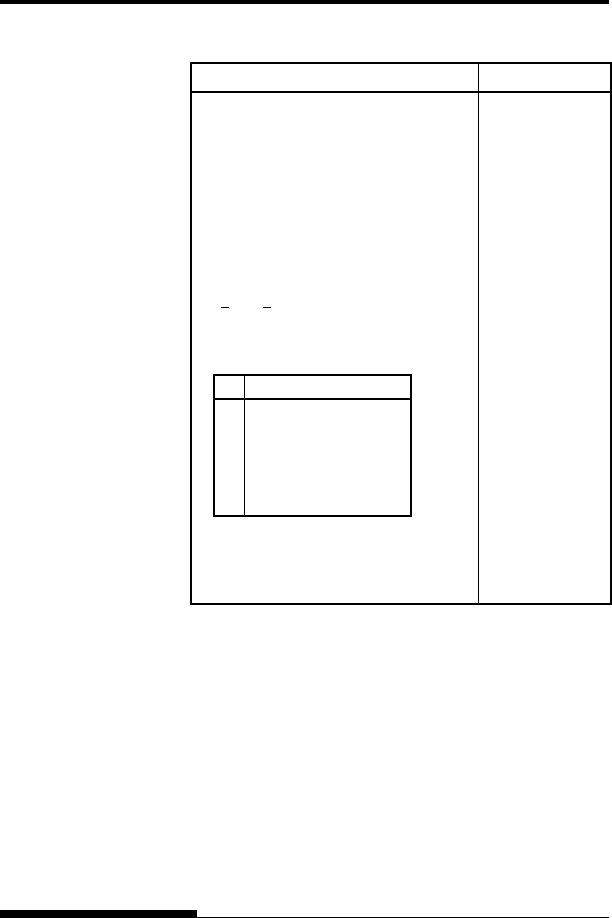
COMMAND SETS
User's Manual C-25
Function Command
Character Set Control
Select character set 1
Select character set 2
Print n1+ n2 × 256 characters from all-
character set
(chars.: codes of characters to print,
0 < chars. < 255)
Print a character from all-character set
(char.: a code of character to print,
0 < char. < 255)
Select code page table n
(0 < n1, n2 < 255) (n = n1+ n2 × 256)
c1c2Code page ID
0
1
3
3
3
3
0
181
82
92
95
97
Ignore command
Code page 437
Code page 850
Code page 860
Code page 863
Code page 865
Clear input buffer
Select printer
Deselect printer (ignore input)
ESC 7
ESC 6
ESC \ (n1)(n2)
(chars.)
ESC ^ (char.)
ESC [ T (n1)(n2)
0 0 (c1)(c2)
CAN
DC1
ESC Q #
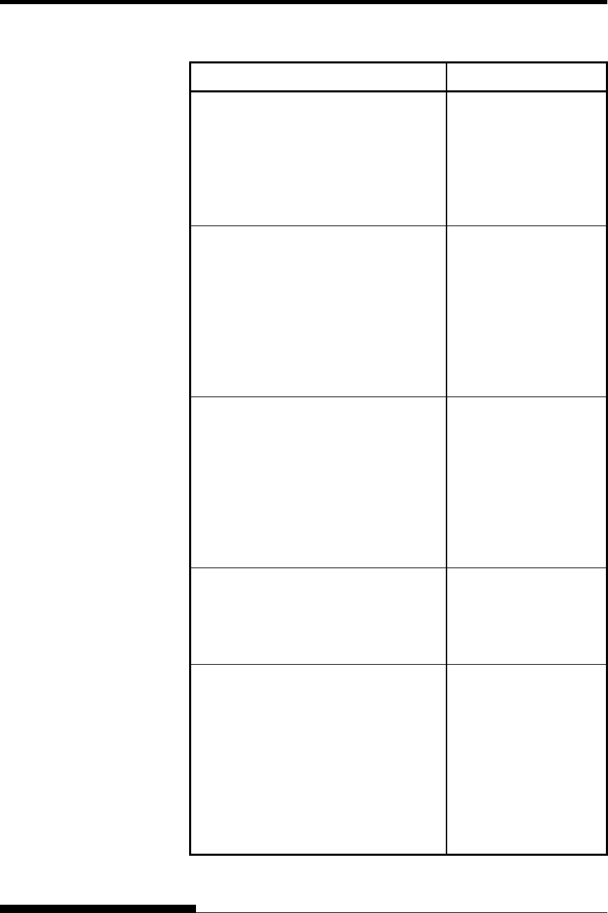
COMMAND SETS (IBM XL24E)
C-26 User's Manual
Function Command
Downloading
Select resident or downloaded font
Ex.n = 0:Resident Draft
2:Resident Courier
4:Downloaded Draft
6:Downloaded Courier
Create download font
ESC I (n)
ESC = (n1) (n2)
ID (m1) (m2) (data)
Bit Image Graphics
Single-density graphics
Double-density graphics
High-speed double-density graphics
Quadruple-density graphics
High-resolution graphics
Select graphics mode (in AG mode only)
ESC K (n1)(n2) (data)
ESC L (n1)(n2) (data)
ESC Y (n1)(n2) (data)
ESC Z (n1)(n2) (data)
ESC [ g (n1)(n2)
(m) (data)
ESC * (m) (c1) (c2)
(data)
Cut Sheet Feeder Control
Feed a sheet from bin 1
Feed a sheet from bin 2
Feed a sheet from bin 3
Eject a page from the printer
Select bin 1 for following pages
Select bin 2 for following pages
Select bin 3 for following pages
Change bins at next page
ESC EM 1
ESC EM 2
ESC EM E
ESC EM R
/ / 1 / /
/ / 2 / /
/ / E / /
/ / C / /
Print Option Control
Friction feed selection
Rear tractor feed selection
Front tractor feed selection
Cut sheet feed selection
/ / F / /
/ / T / /
/ / M / /
/ / S / /
Miscellaneous
Sound the bell
Unidirectional printing on/off
(on:n= 1, off:n= 0)
Add a carriage return to all line feeds
(on:n= 1, off:n= 0)
Printer offline
Enter online setup mode
Select default settings
BEL
ESC U (n)
ESC 5 (n)
ESC j
ESC e ONLINE (data)
ESC [ K (n1)(n2)
(i) (ID) (p1)(p2)
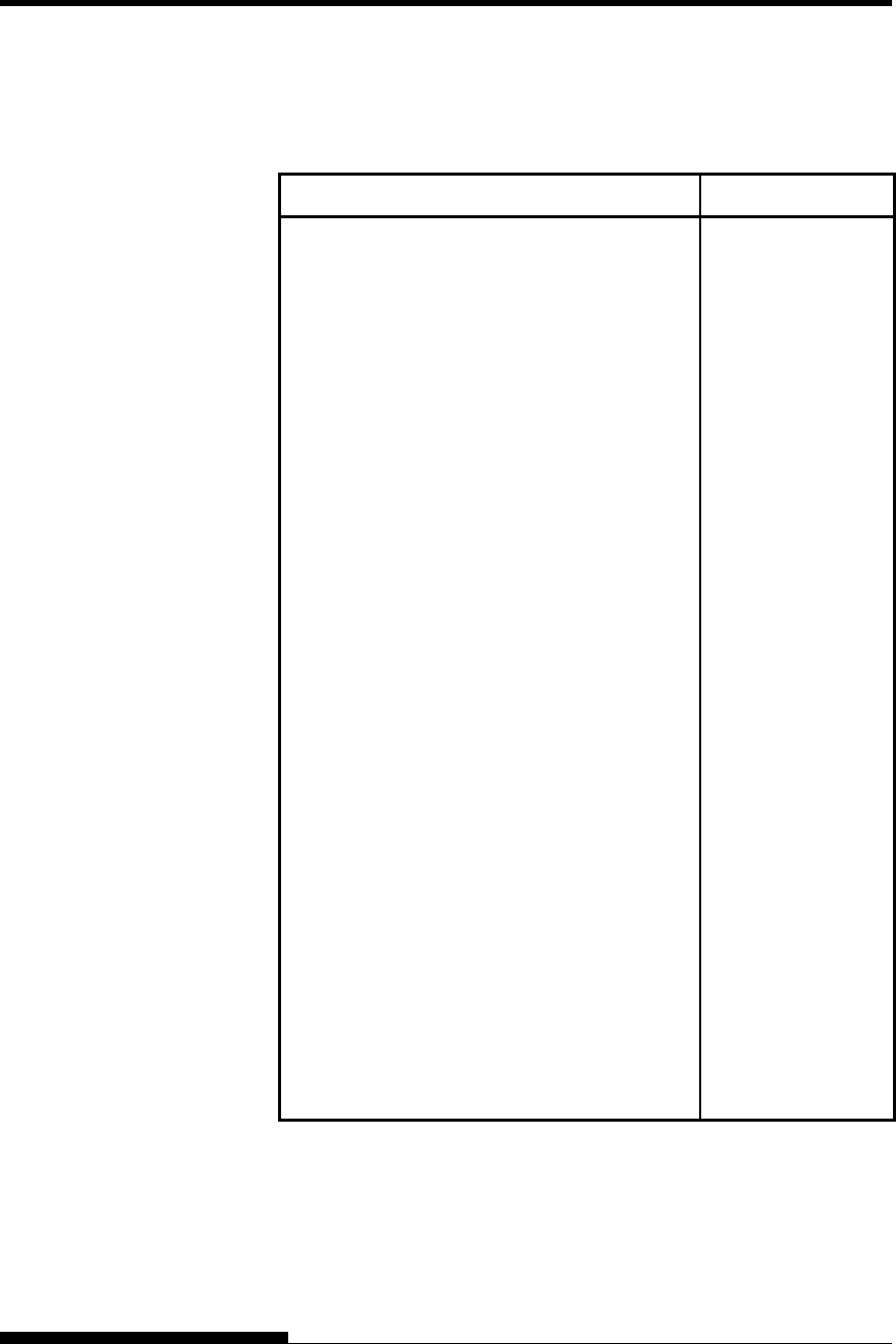
COMMAND SETS
User's Manual C-27
This section describes the printer commands for the Epson ESC/P2
emulation. Asterisks in the “Function” column indicate extended
commands that are not supported by the original printer.
Function Command
Print Mode Control
Double-strike (bold) printing on
Double-strike (bold) printing off
Emphasized (shadow) printing on
Emphasized (shadow) printing off
Italic printing on
Italic printing off
Select character style
n = 0: Normal
1: Outlined
2: Shaded
3: Outlined and shadowed
One-line double-width characters on
One-line double-width characters off
Double-width characters on/off
(on: n= 1, off: n= 0)
Double-height characters on/off
(on: n= 1, off: n= 0)
Condensed characters on
Condensed characters off
Subscript or superscript printing on
(subscript: n= 1, superscript: n= 0)
Subscript and superscript printing off
Underline on/off
(on: n= 1, off: n= 0)
ESC G
ESC H
ESC E
ESC F
ESC 4
ESC 5
ESC q (n)
SO or ESC SO
DC4
ESC W (n)
ESC w (n)
SI or ESC SI
DC2
ESC S (n)
ESC T
ESC - (n)
EPSON ESC/P2
EMULATION
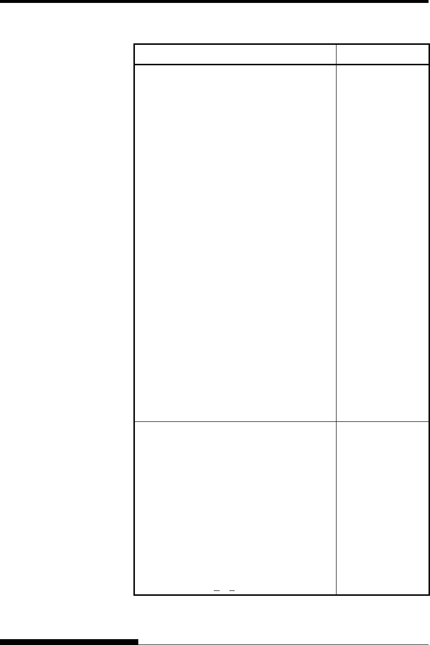
COMMAND SETS (ESC/P2)
C-28 User's Manual
Function Command
Select line
n1 = 3, n2 = 0, d1 = 1
d2 = 0:Ignore command
1:Underline
2:Strike through
3:Overscore
d3 = 0 or 4:Cancel line selection
1:Single line
2 or 3:Double line
5:Single-dotted line
6 or 7:Double-dotted line
Select printing style
This command allows you to combine
various printing styles. The value
of n is the sum of the values of the
styles you want to combine.
n = 0:Pica pitch
1:Elite pitch
2:Proportional spacing
4:Condensed
8:Shadow
16:Bold
32:Double-width
64:Italics
128:Underline
ESC ( - (n1)(n2)
(d1) (d2) (d3)
ESC ! (n)
Horizontal Control
Space
Backspace
Carriage return
Set elite pitch
Set pica pitch
Set 15 CPI
Proportionally spaced characters on/off
(on: n = 1, off: n = 0)
Set inter-character space to n/120 inch (for
draft) or n/180 inch (for letter and
proportional) (0 < n < 127)
SP
BS
CR
ESC M
ESC P
ESC g
ESC p (n)
ESC SP (n)
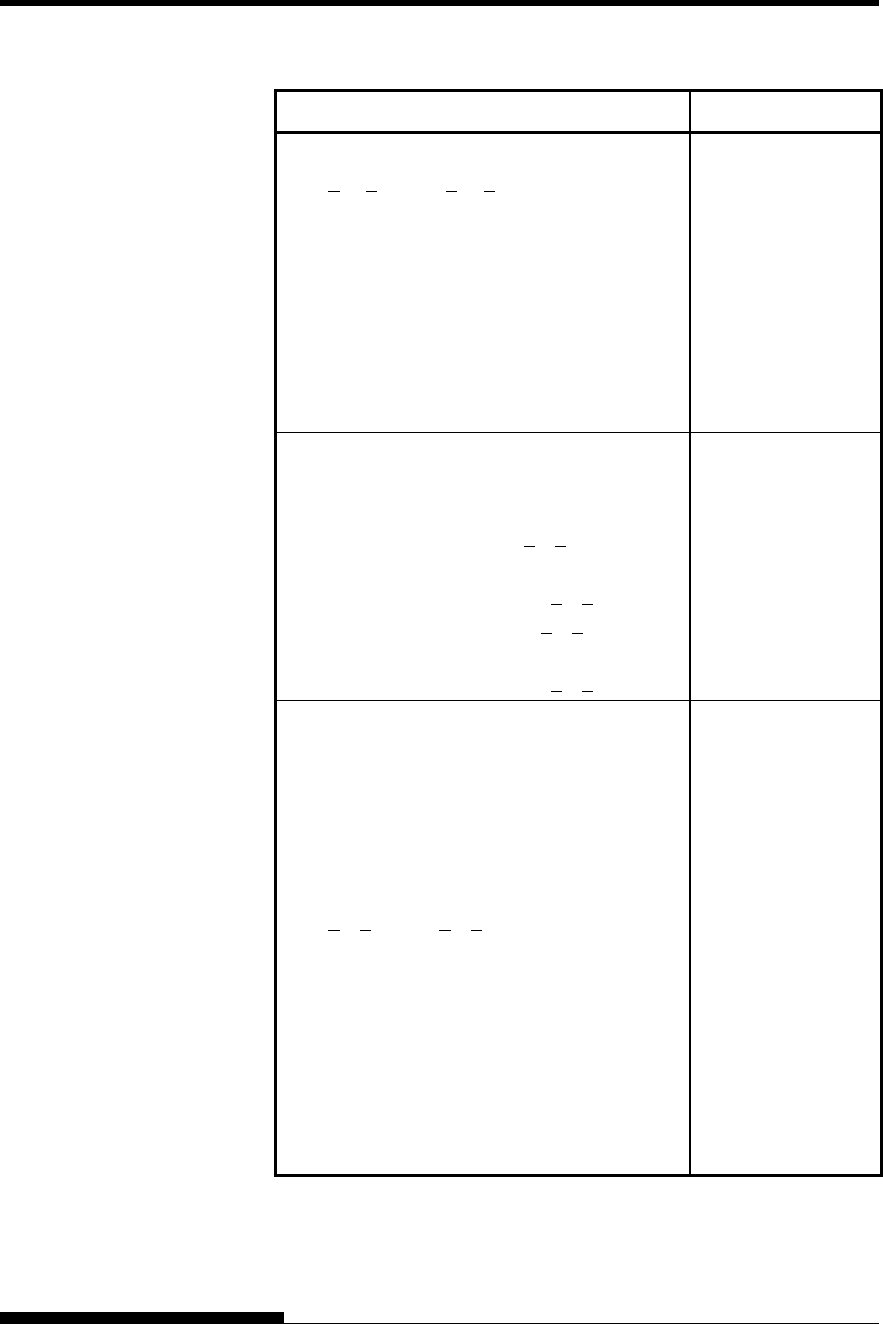
COMMAND SETS
User's Manual C-29
Function Command
Set character pitch to (n1+ n2 × 256)/360 inch
(0 < n1 < 255) (0 < n2 < 4)
Select character pitch (specify unit of pitch)
n1 = 1, n2 = 0
d = 10 to 19: 10/3600 inch = 1/360 inch
d = 20 to 29: 20/3600 inch = 1/180 inch
d = 30 to 39: 30/3600 inch = 1/120 inch
d = 40 to 49: 40/3600 inch = 1/90 inch
d = 50 to 59: 50/3600 inch = 1/72 inch
d = 60 to 69: 60/3600 inch = 1/60 inch
ESC c (n1)(n2)
ESC ( U (n1)(n2) (d)
Vertical Control
Line feed
Form feed
Advance paper n/180 inch (1 < n < 255)
Set line spacing to 1/8 inch
Set line spacing to n/180 inch (0 < n < 255)
Set line spacing to n/60 inch (0 < n < 127)
Set line spacing to 1/6 inch
Set line spacing to n/360 inch (0 < n < 255)
LF
FF
ESC J (n)
ESC 0
ESC 3 (n)
ESC A (n)
ESC 2
ESC + (n)
Tabulation
Horizontal tab execution
Set horizontal tabs
The values of n1 to nk in this
command are the ASCII values of the
print columns (at the current character
width) at which tabs are to be set.
(1 < n < 255) (1 < k < 32)
Move print position n/120 inch (for draft)(*1)
or n/180 inch (for letter)(*1) right from
left margin (n = n1+ n2 × 256)
Move print position n/120(*1) inch (for draft)
Or n/180(*1) inch (for letter) left or right
from the current position
(n = n1+ n2 × 256)
Vertical tab execution
HT
ESC D
(n1)... (nk) NUL
ESC $ (n1)(n2)
ESC \ (n1)(n2)
VT
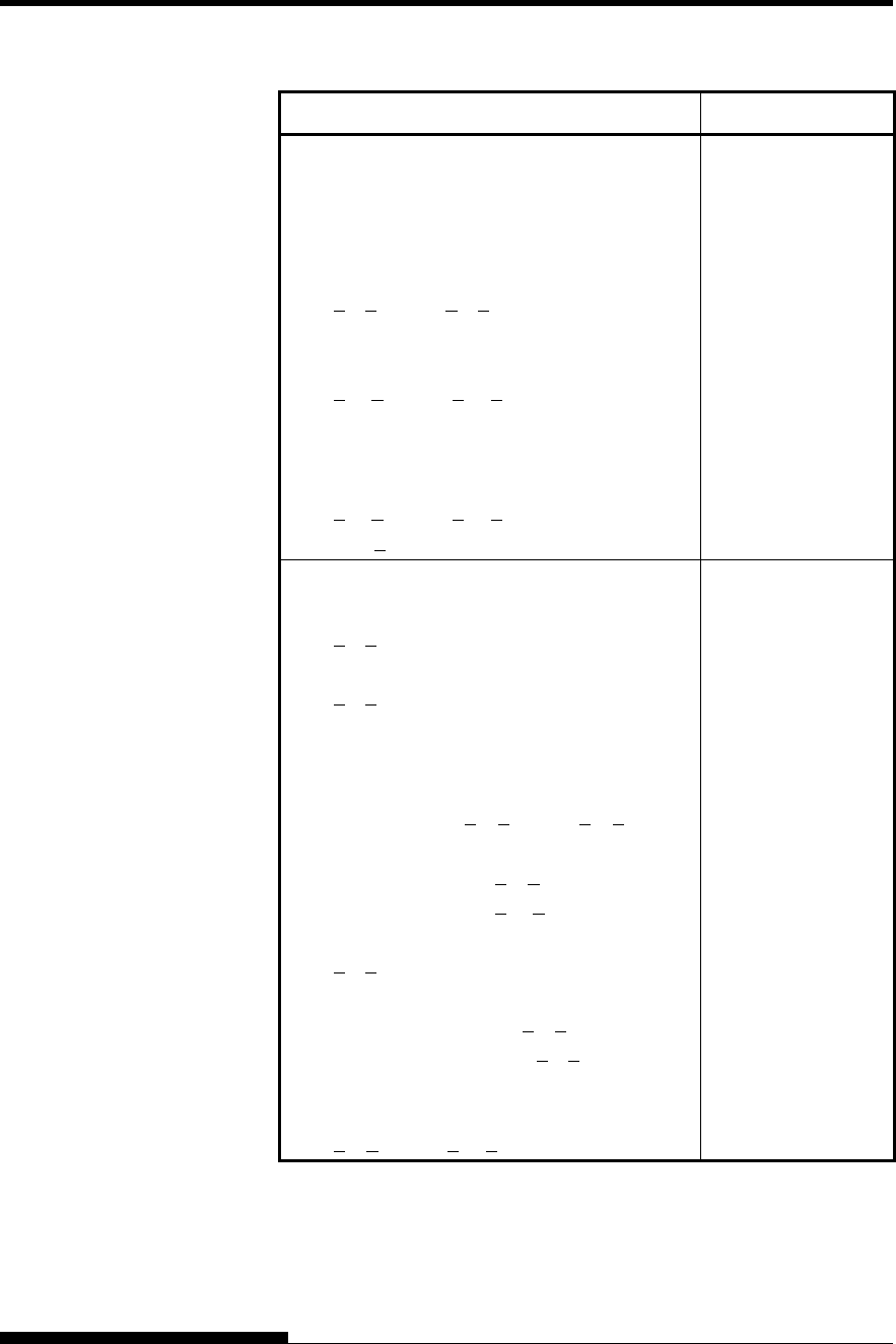
COMMAND SETS (ESC/P2)
C-30 User's Manual
Function Command
Set vertical tabs
The values of n1 to nk in this
command are the ASCII values of the
lines (at the current line spacing)
at which tabs are to be set.
(1 < n < 255) (1 < k < 16)
Move to dot line (d1 + d2 × 256)/360(*1) inch
n1 = 2, n2 = 0
(0 < d1 < 255) (0 < d2 < 127)
Vertical relative move by (d1 + d2 × 256)/360(*1)
Inch
n1 = 2, n2 = 0
(0 < d1 < 255) (0 < d2 < 127)
-32768 < d1 + d2 256 × 32768
ESC B (n1)...
(nk) NUL
ESC ( V (n1) (n2)
(d1) (d2)
ESC ( v (n1) (n2)
(d1) (d2)
Page Formatting
Set right margin to column n
(1 < n < 255)
Set left margin to column n
(0 < n < 255)
Set top and bottom margins from top of page
n1 = 4, n2 = 0
• Top margin = (t1 + t2 × 256)/360(*1) inch
(0 < t1 < 255) (0 < t2 < 127)
• Bottom margin = (b1+b2 × 256)/360(*1) inch
(0 < b1< 255)
(0 < b2 < 127)
Set perforation skip by n lines
(1 < n < 127)
Perforation skip off
Set page length to n lines (1 < n < 127)
Set page length to n inches (1 < n < 22)
Set page length to (d1 + d2 × 256)/360(*1) inch
n1 = 2, n2 = 0
(0 < d1< 255) (0 < d2 < 127)
ESC Q (n)
ESC l (n)
ESC ( c (n1) (n2)
(t1) (t2) (b1) (b2)
ESC N (n)
ESC O
ESC C (n)
ESC C NUL (n)
ESC ( C (n1) (n2)
(d1) (d2)
*1 The value depends on the pitch set by the ESC (U command.
The default is 1/360 inch.
COMMAND SETS
User's Manual C-31
Function Command
Character Set Control
Select character set 1
Select character set 2
Select character set table
n = 0:Italics character set
1:Graphics character set
2:Downloaded character set
3:Graphics character set
Select international character set
n = 0:USA
1:France
2:Germany
3:United Kingdom
4:Denmark 1
5:Sweden
6:Italy
7:Spanish 1
8:Japan
9:Norway
10:Denmark 2
11:Spanish 2
12:Latin America
13:Korea
64:Legal
ESC 7
ESC 6
ESC t (n)
ESC R (n)
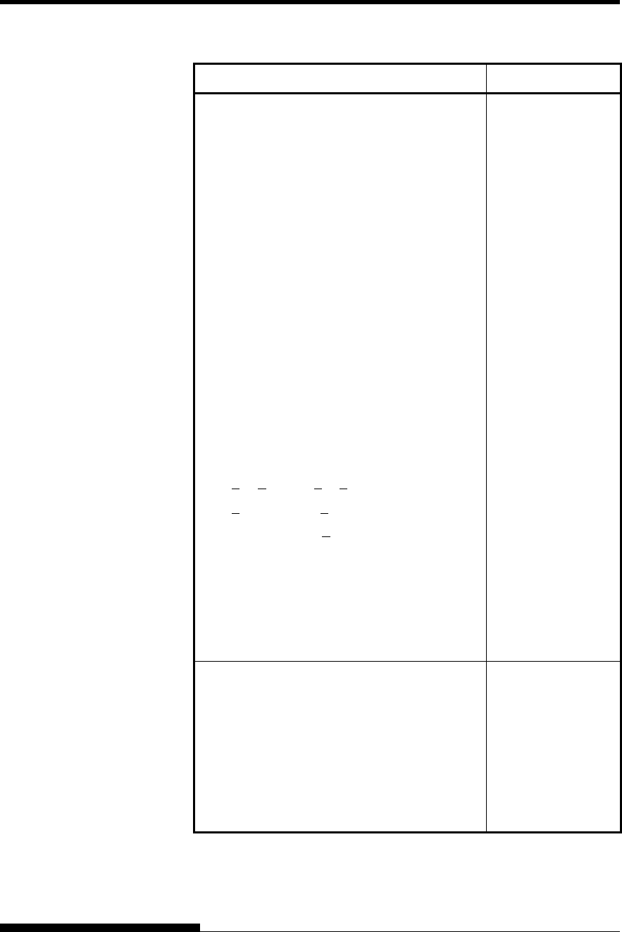
COMMAND SETS (ESC/P2)
C-32 User's Manual
Function Command
Assign a character set to active character set
number 0 to 3
n1 = 3, n2 = 0
d1 = 0:Active character set number 0
1:Active character set number 1
2:Active character set number 2
3:Active character set number 3
d2 = 0:Italic
1:PC 437 (USA)
3:PC 850 (Multilingual)
7:PC 860 (Portugal)
8:PC 863 (Canada-French)
9:PC 865 (Norway)
d3 = 0
Print n1+ n2 × 256 characters from all-
character set
(0 < n1 < 255) (0 < n2 < 127)
(0 < n1 + n2 × 256 < 255)
(0 character codes < 254)
Clear input buffer
Delete a character
Force most significant bit to 1
Force most significant bit to 0
Cancel control over most significant bit
ESC ( t (n1) (n2)
(d1) (d2) (d3)
ESC ( ^ (n1)(n2)
(character codes)
CAN
DEL
ESC >
ESC =
ESC #
Font Selection and Downloading
Select font
n = 0:Resident character set
1:Downloaded character set
Select letter or draft quality
n = 0:Draft
1:Letter
ESC % (n)
ESC x (n)
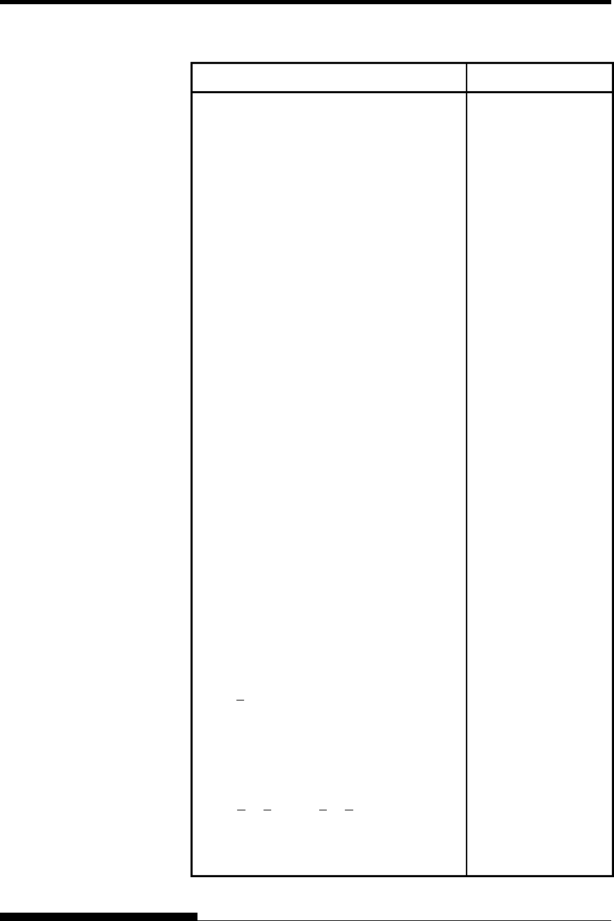
COMMAND SETS
User's Manual C-33
Function Command
Select type style
• Bitmap font:
n = 0:Courier
1:Courier
2:Courier
3:Prestige
4:Courier
5:OCR-B
6:OCR-A
7:Courier
8:Courier
9:Courier
• Scalable font:
n = 0:Timeless
1:Nimbus Sans
®
2:Courier
3:Timeless
4:Timeless
5:Timeless
6:Timeless
7:Timeless
8:Timeless
9:Timeless
Set scalable font mode
• m sets character pitch.
m = 0:Keep previous pitch
1:Set proportional space mode
m > 5:Select character pitch
(m/360 inch)
(Reset proportional space mode)
• n1 and n2 set point size of font.
Point size = (n1 + n2 × 256) × 0.5 point
(0 < n1 < 255) (0 < n2 < 127)
Copy resident character set to download area
Create download font
ESC k (n)
ESC X m (n1)(n2)
ESC : NUL(n)(s)
ESC & NUL (n1)(n2)
(d0) (d1) (d2) (data)
* Indicates extended commands not supported by the original printer.
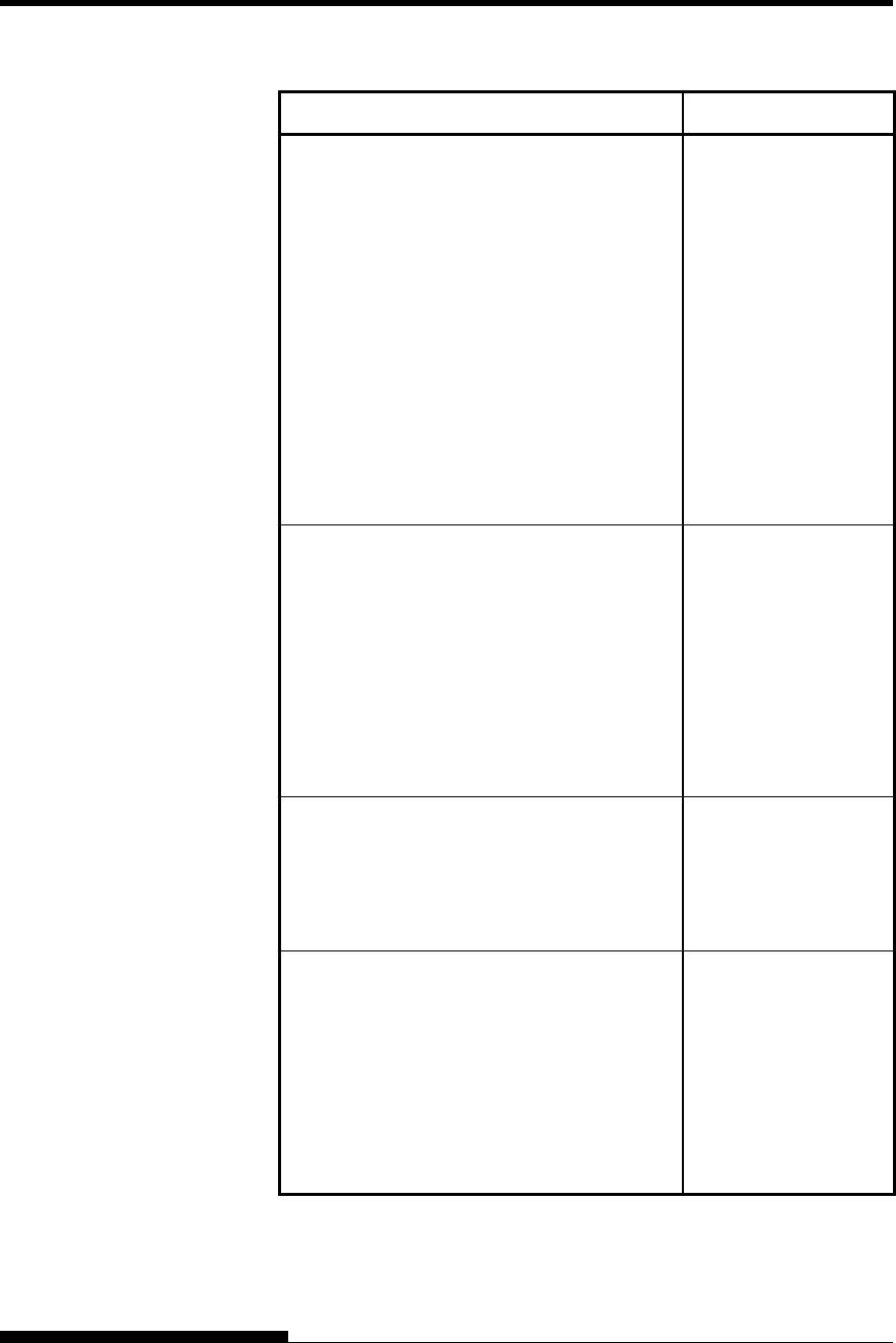
COMMAND SETS (ESC/P2)
C-34 User's Manual
Function Command
Bit Image Graphics
Graphics type m graphics
Bit image mode definition
Single-density graphics
Double-density graphics
High-speed double-density graphics
Quadruple-density graphics
Select raster image graphics
n1 = 1, n2 = 0
d= 1: Raster image graphics mode
Print raster image graphics
ESC * (m) (n1)(n2)
(data)
ESC ? (s) (n)
ESC K (n1)(n2) (data)
ESC L (n1)(n2) (data)
ESC Y (n1)(n2) (data)
ESC Z (n1)(n2) (data)
ESC ( G (n1)(n2) (d)
ESC . (c)(v) (h) (m)
(n1)(n2) (data)
Cut Sheet Feeder Control
Feed a sheet from bin 1
Feed a sheet from bin 2
Feed a sheet from bin 3
Eject a page from the printer
Select bin 1 for following pages
Select bin 2 for following pages
Select bin 3 for following pages
Change bins at next page
ESC EM 1
ESC EM 2
ESC EM E
ESC EM R
/ / 1 / /
/ / 2 / /
/ / E / /
/ / C / /
Print Option Control
Friction feed selection
Rear tractor feed selection
Front tractor feed selection
Cut sheet feed selection
/ / F / /
/ / T / /
/ / M / /
/ / S / /
Miscellaneous
Sound the bell
Move print head to home position
Unidirectional printing on/off
(on:n = 1, off:n = 0)
Initialize printer
Enter online setup mode
BEL
ESC <
ESC U (n)
ESC @
ESC e ONLINE
(data)

User's Manual D-1
D
APPENDIX D INTERFACE INFORMATION
INTERFACE INFORMATION
This printer can communicate with a computer
through a Centronics parallel interface, a RS-232C
serial interface, a USB interface, or a LAN interface. You can specify
the interface selection mode so that the printer uses which interface or it
can automatically select the interface from which it first receives data.
This appendix provides information you may need for wiring your own
interface cables or for programming computer-to-printer communications.
Most users do not need the information in this appendix. To simply
connect your printer to your computer, follow the instructions in Chapter
2.
This parallel interface can operate in the following two modes:
• Unidirectional (forward channel) mode or conventional mode: This
printer supports a conventional Centronics interface.
• Bidirectional (forward/reverse channel) mode or nibble mode: This
printer supports a bidirectional communication per Nibble mode of
the IEEE 1284 Standard.
The cable connector at the printer side should be a shielded, Amphenol
DDK 57FE-30360 or equivalent.
The connector pin assignments are given in the following tables by
modes. In the tables:
• “Input” denotes a signal from the computer to the printer.
• “Output” denotes a signal from the printer to the computer.
• The return lines specified in the second column represent
twisted pairs, with one side connected to signal ground.
• The standard signal levels are 0.0 to +0.4 V (low), and +2.4 to
+5.0 V (high).
PARALLEL
INTERFACE
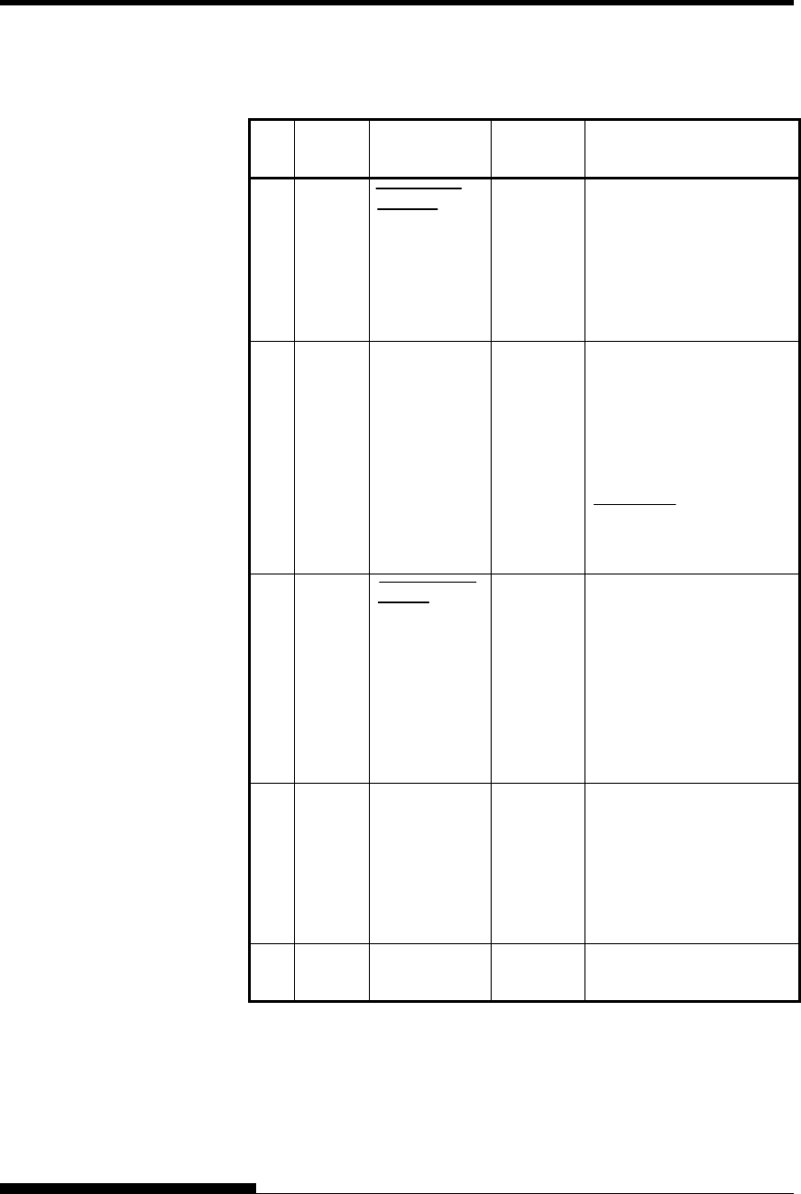
INTERFACE INFORMATION
D-2 User's Manual
Compatible Mode
Pin
No. Return
Pin No. Signal Name Direction Description
1 19
Data Strobe
(DSTB)
Input This signal is a strobe
pulse for reading data
(Data 1 to 8). The printer
reads data when this signal
is low. The pulse width
must be 1 μs or more at
the receiving terminal.
2-9 20-27 Data 1 to 8 Input Data 8 (pin 9) is the most
significant bit; however,
this pin is not used in 7-bit
ASCII communications.
Logical 1 signals must go
high at least 1 μs before
the falling edge of the
Data Strobe signal and
must stay high for at least
1 μs after the rising edge.
10 28
Acknowledge
(ACK)
Output This pulse signal indicates
that the printer has
received data and is ready
to accept the next set of
data.
This signal is also sent
when the printer is
switched from offline to
online.
11 29 Busy Output Data cannot be received
when this signal is high.
This signal is high during
data entry, when the
printer is offline, when the
buffer is full, or when an
error occurs.
12 30
Paper Empty
(PE)
Output This signal is high when
the printer is out of paper.
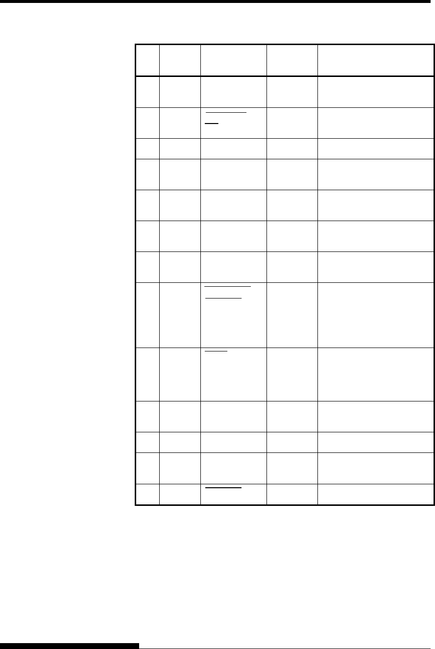
INTERFACE INFORMATION
User's Manual D-3
Pin
No. Return
Pin No. Signal Name Direction Description
13 − Select
(SLCT)
Output This signal is high when
the printer is online.
14 − Auto Feed
XT
Input Not used
15 − − − No connection
16 − Signal
Ground
− Logic ground level (0 V)
17 − Frame
Ground
− Printer chassis ground line.
FG and SG are connected.
18 − +5 V Output +5 V source (up to 300
mA)
19-
30
− Signal
Ground
− Twisted pair return lines
31 − Input Prime
(INPRM)
If this signal is low for
more (INPRM) than 50 μs,
the printer is reset to the
initial condition and is
placed online.
32 − Fault Output
This signal is low when
the printer is offline, paper
is out, or when there is a
printer error.
33 − Signal
Ground
− Logic ground level (0 V)
34 − − − No connection
35 − +5 VR Output Pulled up to +5 V through
a 3.3 kΩ resistor
36 − SLCT-IN Input Not used
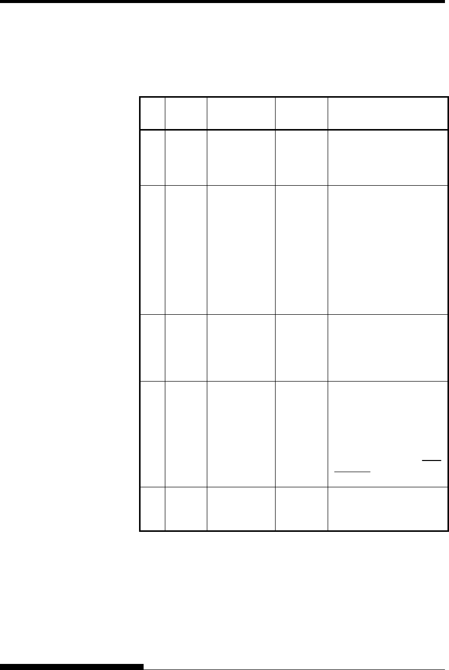
INTERFACE INFORMATION
D-4 User's Manual
Nibble Mode
Pin numbers 2 to 9, 15 to 31, and 33 to 35 are the same as the
conventional mode.
Pin
No. Return
Pin No. Signal Name Direction Description
1 19 Host Clock Input This signal is set high
when the host requests the
reverse data transfer phase
(nibble mode).
10 28 Printer Clock Output Reverse data transfer
phase:
This signal goes high
when data being sent to the
host is established.
Reverse idle phase:
This signal is set low then
goes high to interrupt the
host, indicating that data is
available.
11 29 Printer Busy Output Reverse data transfer
phase:
Data bit 3, data bit 7, then
forward path (host to
printer) busy status
12 30 Ack Data Req Output Reverse data transfer
phase:
Data bit 2, then data bit 6
Reverse idle phase:
This signal is set high until
the host requests data and,
after that, follows the Data
Available signal.
13 − X Flag Output Reverse data transfer
phase:
Data bit 1, then data bit 5
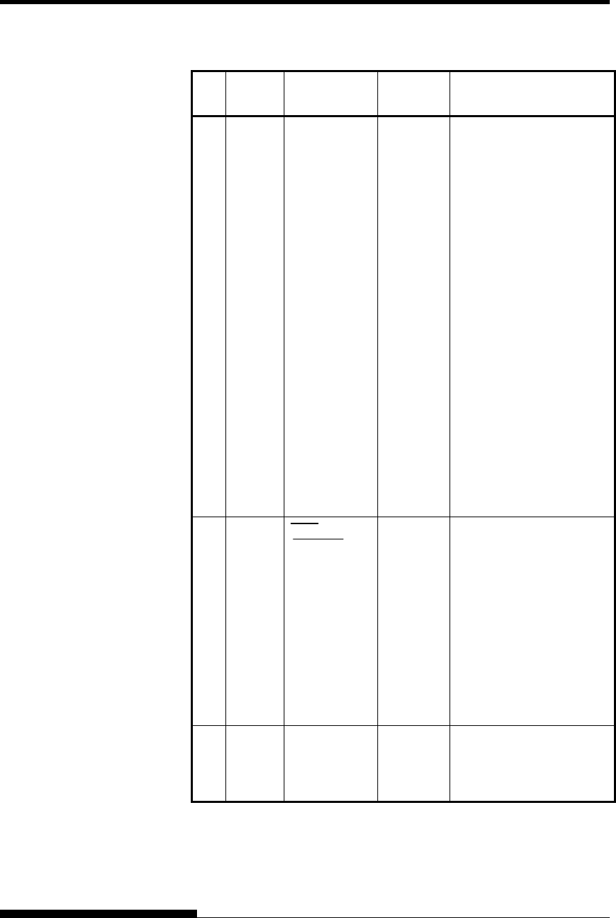
INTERFACE INFORMATION
User's Manual D-5
Pin
No. Return
Pin No. Signal Name Direction Description
14 − Host Busy Input Reverse data transfer
phase:
This signal is set low when
the host can receive data,
and goes high when the
host has received data.
Following a reverse data
transfer, the interface
enters the reverse idle
phase when the Host Busy
signal goes low and the
printer has no data.
Reverse idle phase:
This signal goes high
when the Printer Clock
signal goes low so that the
interface re-enters the
reverse data transfer phase.
If it goes high with the
1284 Active signal low,
the 1284 idle phase is
aborted and the interface
returns to the compatibility
mode.
32 − Data
Available
Output Reverse data transfer
phase:
This signal is set low when
the printer is ready to send
data to the host. During
the data transfer, it is used
as data bit 0 (LSB), then
data bit 4.
Reverse idle phase:
This signal is used to
indicate that data is
available.
36 − 1284 Active Input This signal goes high to
cause the printer to enter
the reverse data transfer
phase (nibble mode).
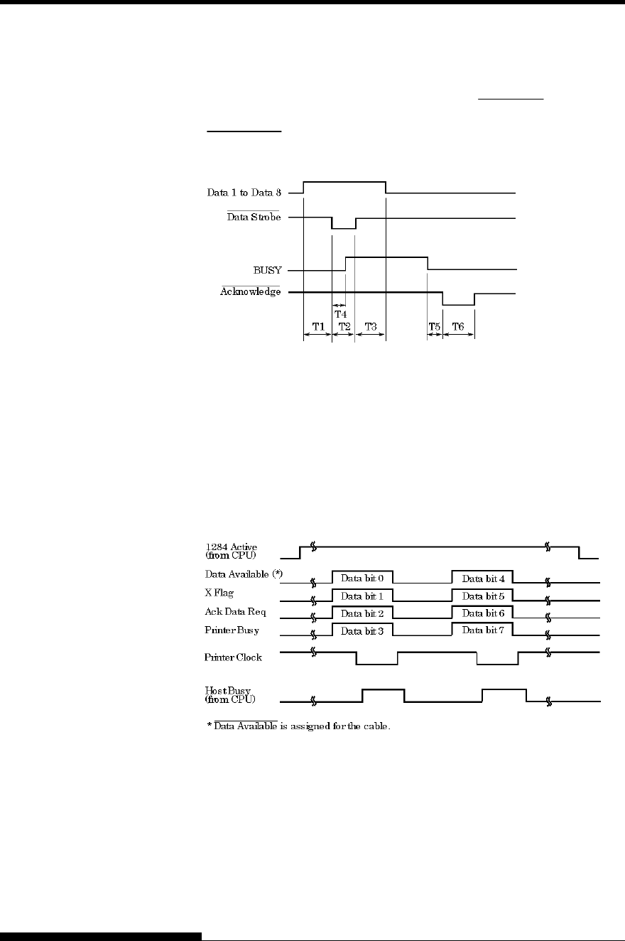
INTERFACE INFORMATION
D-6 User's Manual
Data Transmission Timing
In unidirectional mode (conventional Centronics interface), this printer
guarantees the received data when the Data and Data Strobe signals from
the computer have the following timing with respect to the Busy and
Acknowledge signals from the printer.
T1, T2, T3 > 1 μs
T4 < 1 μs
0 μs < T5 < 3 μs
2 μs < T6 < 6 μs
In bidirectional mode (nibblemode), this printer can send data to the
computer. Data is sent in units of four bits (nibble) using four output
signal lines as data paths. The following outlines one byte of data sent
during reverse data transfer phase in nibble mode.
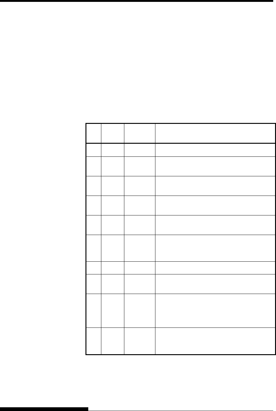
INTERFACE INFORMATION
User's Manual D-7
RS-232C is the standard serial interface for data terminal equipment. The
cable connector at the printer side should be a D-subminiature Cannon or
Cinch DB-25P male connector or equivalent that conforms to EIA
standards.
The table that follows shows the pin assignments commonly used by
most computers. In the table:
• “Input” denotes a signal from the computer to the printer.
• “Output” denotes a signal from the printer to the computer.
• The signal level for mark state (logical 1) is -3 V or lower; for
space state (logical 0), it is +3 V or higher.
Pin
No. Signal
Name Direction Description
1 FG − Frame Ground
2 TD Output
This pin carries information from the printer
to the computer.
3 RD Input
Received Data. This pin carries information
from the computer to the printer.
4 RTS Output
Request To Send. Spaces are sent when the
printer is ready to transmit data.
5 CTS Input Clear To Send. Spaces are sent when the
computer is ready to receive data.
6 DSR Input Data Set Ready. Spaces are sent when the
computer has been powered on and is ready
to receive or transmit data.
7 SG − Signal Ground (common return)
8 CD Input
Carrier Detect. Spaces are sent when the
computer allows the printer to receive data.
11 RC Output
Reverse Channel. This signal is used instead
of the DTR signal in the RC protocol.
Spaces are sent when the printer is ready to
receive or transmit data.
20 DTR Output Data Terminal Ready. Spaces are sent when
the printer has been powered on and is ready
to receive or transmit data.
SERIAL INTERFACE

INTERFACE INFORMATION
D-8 User's Manual
Serial Options
The serial options for the computer and the printer must match. Use the
printer control panel, the computer operating system, or your software to
change options specified as “selectable.”
Transmission mode: Asynchronous, full duplex, or half duplex
(selectable)
Speed: 150, 300, 600, 1200, 2400, 4800, 9600, or
19200 baud (selectable)
Data bits: 7 or 8 bits (selectable)
Parity bit: Odd, even, mark, space, or none (selectable)
Start bit: 1 bit
Stop bit: 1 or 2 bits (selectable)
Protocol: XON/XOFF (DC1/DC3), DTR (Data Terminal
Ready), or RC (Reverse Channel) (selectable)
Buffer size: 256, 2K, 8K, 24K, 32K, 96K, or 128K bytes
(selectable)
Cable Wiring
This printer allows two types of serial communication control: DSR-
enabled and DSR-disabled. The type of control required is determined
by your computer requirements. The type of control also affects the way
the interface cable is wired. To determine whether you need DSR-
enabled control or DSR-disabled control, use the printer HARDWRE
function (see Chapter 5).
DSR-disabled control offers simpler cabling and communication than
does DSR-enabled control. DSR-disabled control can be used to
interface with an IBM PC and most other personal computers. With
DSR-disabled control, the input control signals DSR, CTS, and CD are
always considered high, regardless of their actual states. Therefore, no
wire connection for these pins is required. The following figure shows
the wiring required for connection to an IBM PC.
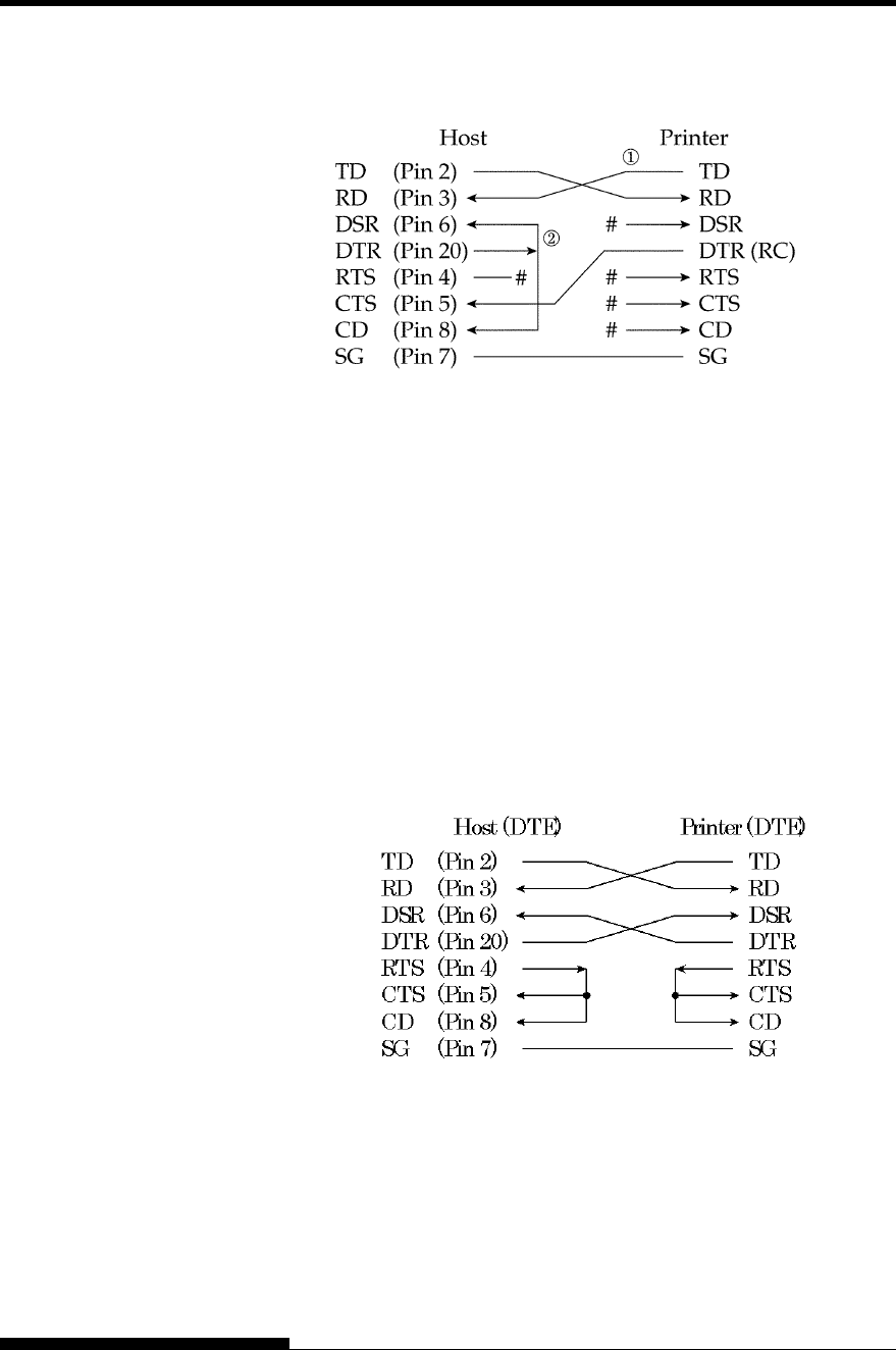
INTERFACE INFORMATION
User's Manual D-9
# indicates an open wire.
Wire q is unnecessary for the DTR (or RC) protocol.
Some computers may not require wire w.
DSR-enabled control enables communication using an RS-232C
interface. The CTS and DSR input control signals are enabled; CD is
ignored. DSR must be high when the printer receives data. If the printer
has data to be transmitted to the computer, the printer transmits the data
when both DSR and CTS are high.
When using DSR-enabled control, use a straight-through cable to
connect to a DCE (data communications equipment) device. Use a null-
modem cable to connect to a DTE (data terminal equipment) device, as
shown below.
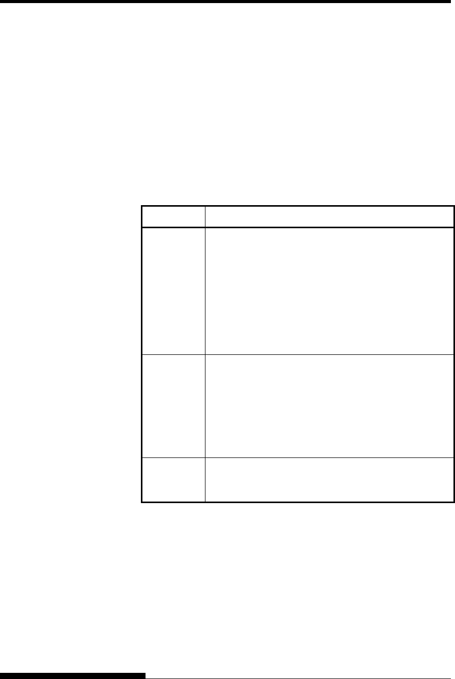
INTERFACE INFORMATION
D-10 User's Manual
Serial Protocols
A protocol is a set of instructions that control the way data is transmitted
between devices such as a computer and printer. The protocol ensures
that the computer does not send information to the printer faster than the
information can be processed. By telling the computer when the printer
can receive data, the protocol prevents the printer s buffer from
overflowing.
This printer offers a choice of four different protocols for connection to a
variety of computers: XON/XOFF, DTR, and RC. If you computer
documentation does not recommend a particular protocol, try DTR. The
following table describes the three protocols.
Protocol Description
XON/XOFF
(DC1/DC3)
When the printer is ready to receive data, it sends the
XON (DC1) code (hex 11). When fewer than 255 bytes
of space remain in the buffer (or when the printer is taken
offline), the printer sends the XOFF (DC3) code (hex 13).
(When the input buffer is configured for 256 bytes, the
buffer limit is reduced from 255 bytes to 63 bytes.) The
computer must stop transmitting data within 255 (63)
characters of receiving the XOFF code, or information
may be lost. If paper runs out, the printer sends an NAK
code (hex 15).
DTR DTR is a hardware protocol; that is, the DTR signal on
interface cable pin 20 is used to control the flow of data
rather than transmission of a character code. When the
printer is ready to receive data, pin 20 is high. When
fewer than 255 (63) bytes of space remain in the buffer
(or when the printer is taken offline), pin 20 is low. The
computer must stop transmitting data within 255 (63)
characters of DTR being low, or information may be lost.
RC The RC protocol is the same as the DTR protocol, except
that the Reverse Channel signal (pin 11) is used instead of
the Data Terminal Ready signal (pin 20).
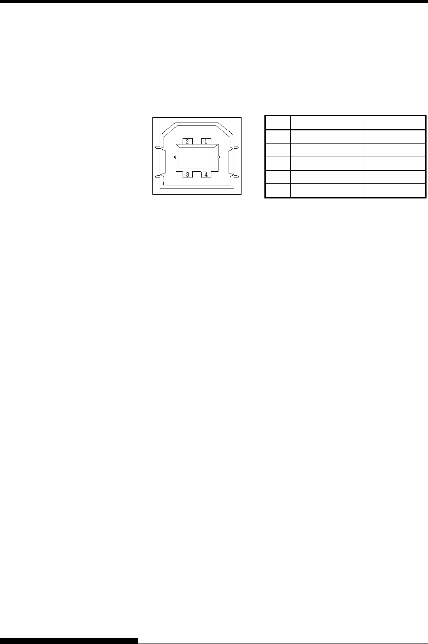
INTERFACE INFORMATION
User's Manual D-11
Cable
This printer supports the USB 1.1 Full speed specification. To connect
to the host, use USB 2.0-compliant INF cables (5 meters (196 inch) or
shorter). (Use the shielded cables.)
Connector pin alignment
No. Signal line name Function
1 vbus Power supply
2 D- Data transfer
3 D+ Data transfer
4 GND Signal ground
Shell Shield
- Connector specification
Printer side
Cable side
Type B receptacle (female)
Upstream port
Type B plug (male)
Specification
- Basic specification USB interface compliant
Note
It does not guarantee all operations on hosts.
- Power control Self-power device
- Transmission mode Full speed (Maximum 12 Mbps
+0.25%)
USB INTERFACE
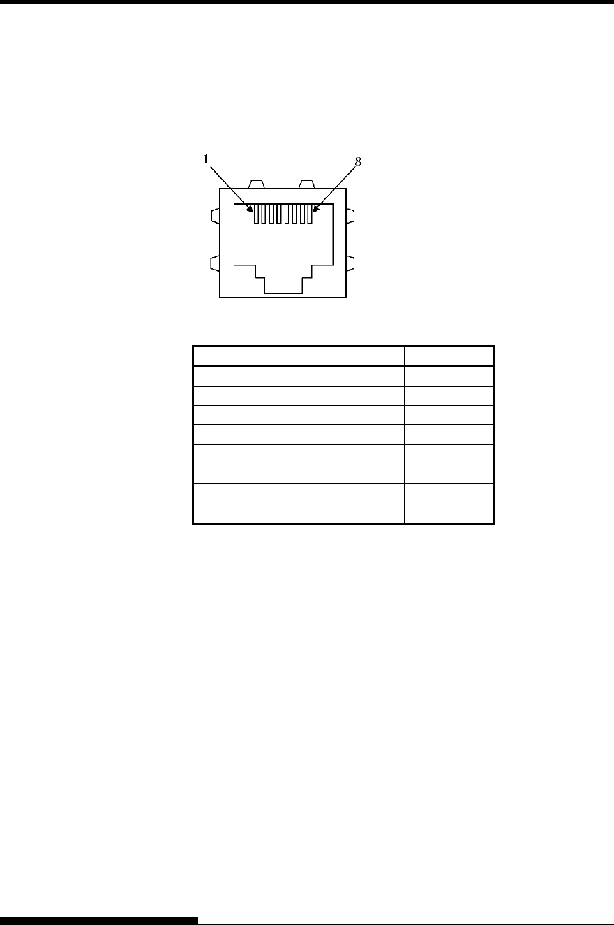
INTERFACE INFORMATION
D-12 User's Manual
Cable
This printer supports the 10Base-T and 100Base-TX cables.
Connector pin alignment
No. Signal line name DIR Function
1 TXO+ NIC-HUB Transmit data +
2 TXO- NIC-HUB Transmit data -
3 RXI+ HUB-NIC Receive data +
4 − − −
5 − − −
6 RXI- HUB-NIC Receive data -
7 − − −
8 − − −
LAN INTERFACE
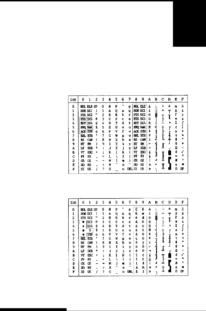
User's Manual E-1
E
APPENDIX E CHARACTER SETS
CHARACTER SETS
Below are character sets 1 and 2 of Code Page 437,
available in the DPL24C PLUS command set and
the IBM Proprinter XL24E emulation. Characters
enclosed in boxes differ for sets 1 and 2.
Characters in set 2 also vary with the national character set.
Code Page 437 is for the USA character set.
Code Page 437 Character Set 1
Code Page 437 Character Set 2
CHARACTER SETS
1 AND 2
(DPL24C PLUS AND
IBM XL24E
EMULATION)
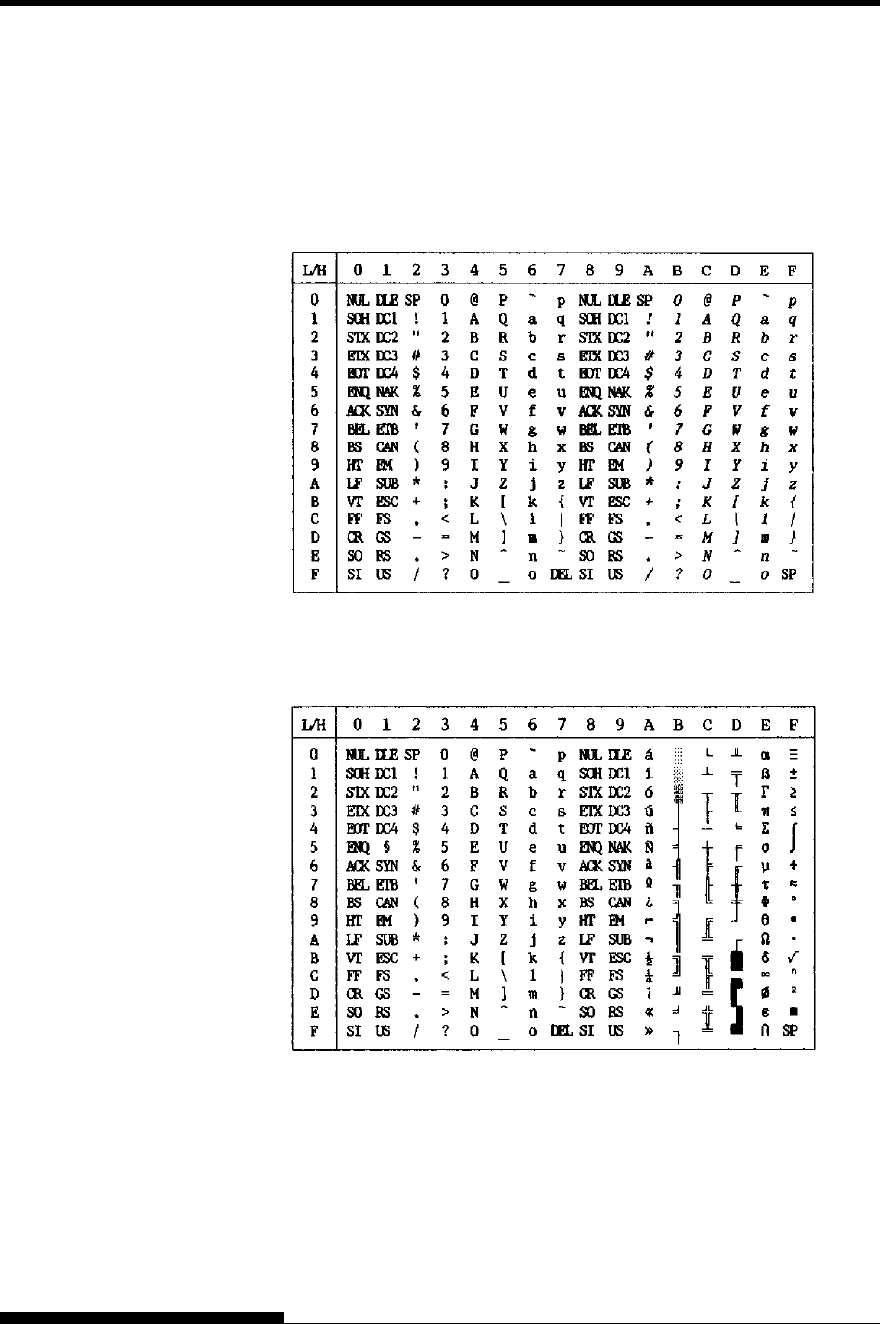
CHARACTER SETS
E-2 User's Manual
The following shows character sets available in the Epson ESC/P2
emulation. Characters differ in codes 128 to 255 (hex 80 to FF).
Italic Character Set
Graphics Character Set 1
ITALIC AND
GRAPHICS
CHARACTER SETS
(ESC/P2
EMULATION)
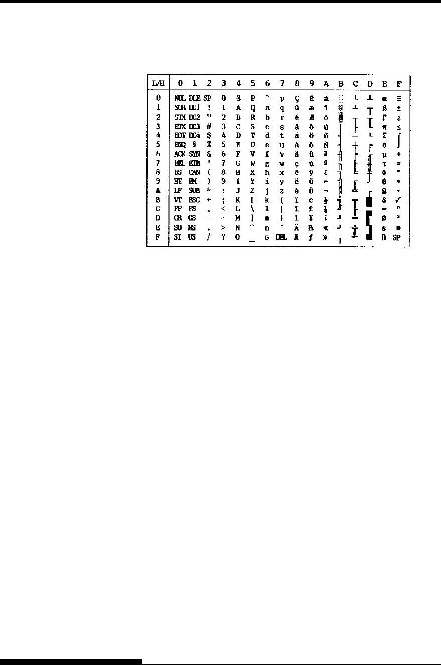
CHARACTER SETS
User's Manual E-3
Graphics Character Set 2
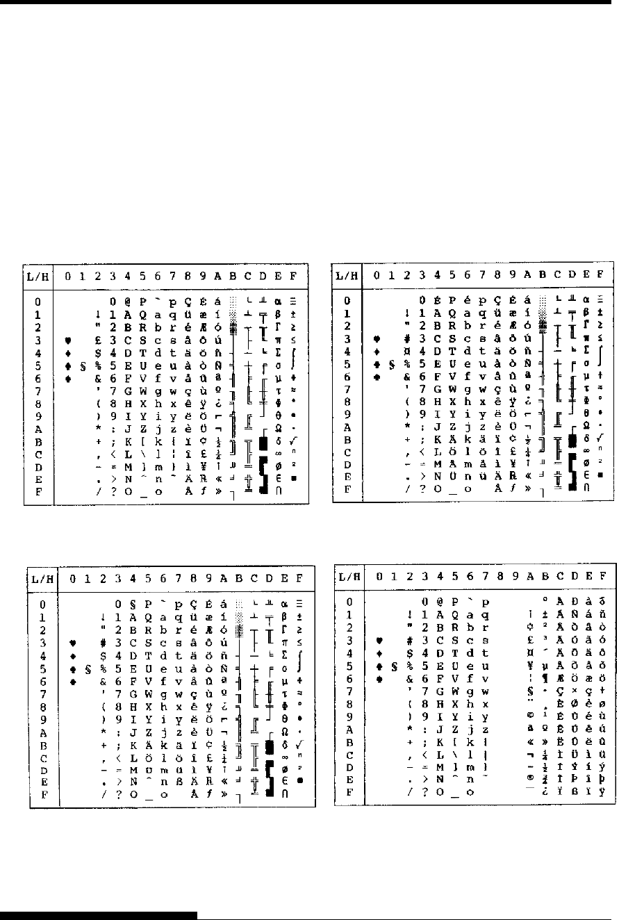
CHARACTER SETS
E-4 User's Manual
Below are the 52 national character sets available for all emulations of
this printer. These character sets support different characters and
symbols specific to different languages. Note that these tables are for
Courier 10, a resident font, and that some national character sets do not
have some characters and symbols whose use depends on resident fonts.
For details, see the table at the end of this appendix.
When the following character sets are used with the Epson ESC/P2
emulation, the printing of FFh code characters is not supported.
ECMA94, ISO8859, ISO-LTN, ISO-TUK, CYRILIC, LATIN-9
NATIONAL
CHARACTER SETS
(ALL EMULATIONS)
UK (British English) SWEDISH (Swedish)
GERMAN (German) ISO8859/ECMA94 (ISO 8859-1/ECMA94)
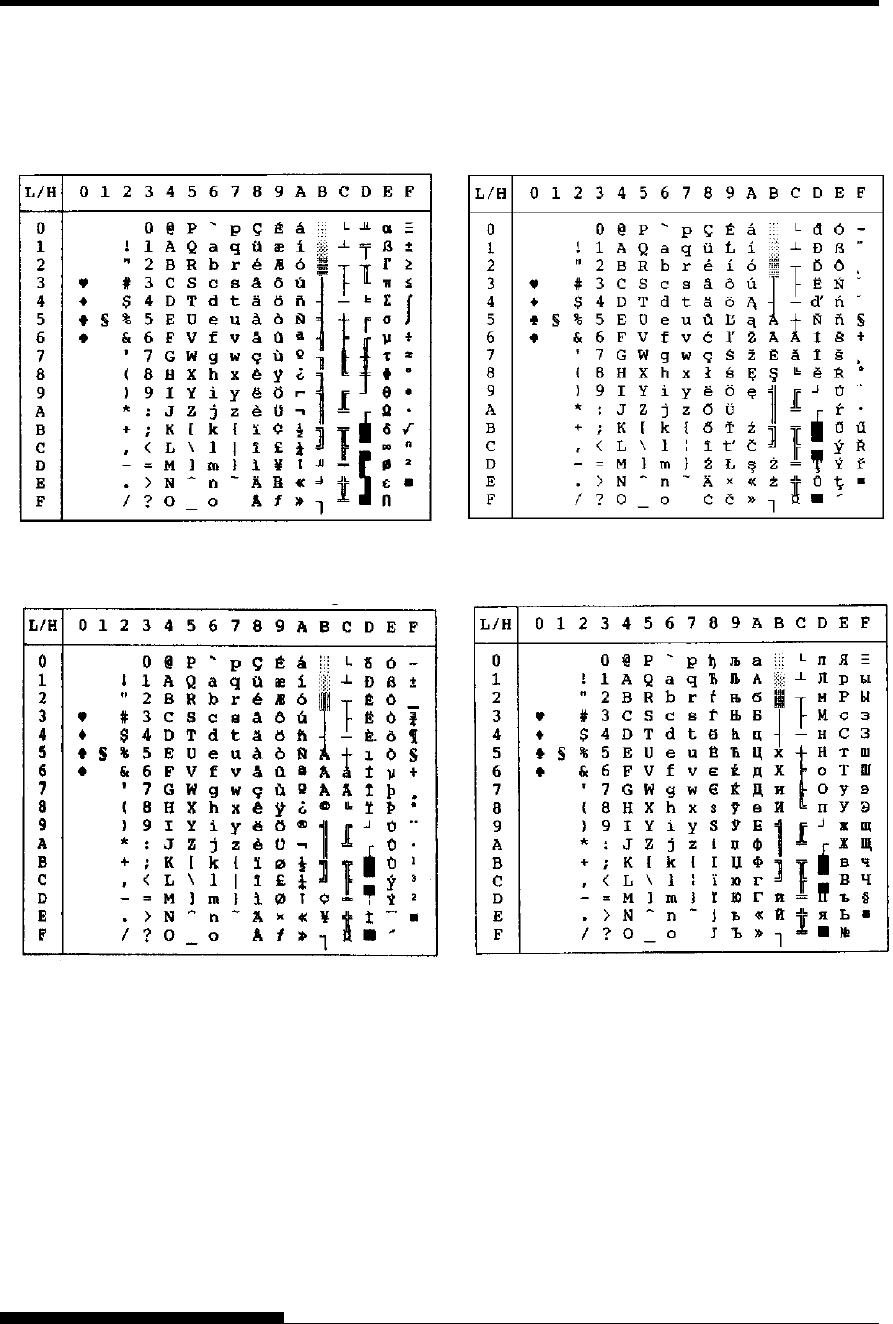
CHARACTER SETS
User's Manual E-5
PAGE437/USA (Code Page 437/USA) PAGE852/PG852-T (Code Page 852)
PAGE850 (Code Page 850(Multilingual)) PAGE855 (Code Page 855)
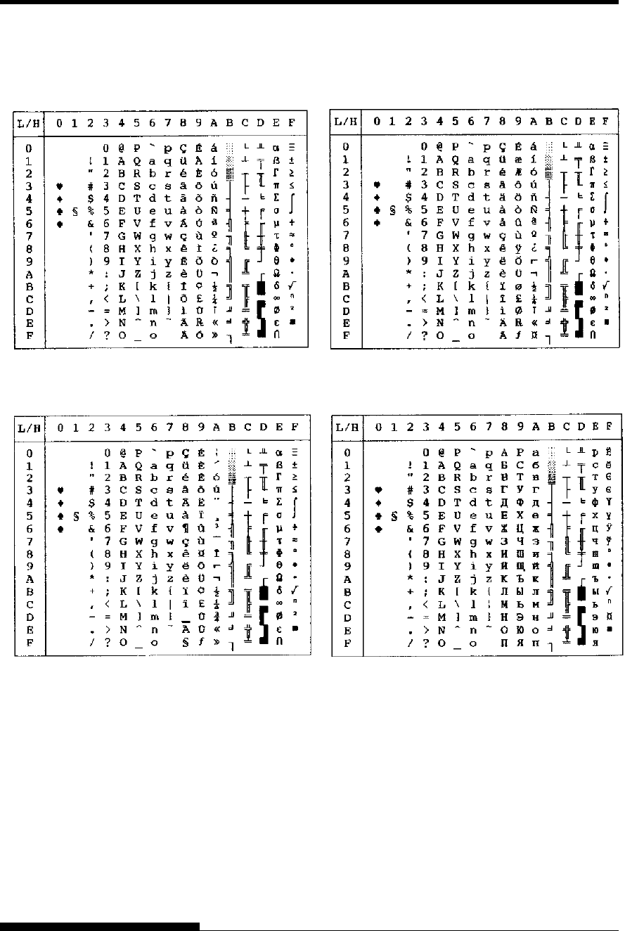
CHARACTER SETS
E-6 User's Manual
PAGE860 (Code Page 860(Portugal)) PAGE865 (Code Page 865(Nordic))
PAGE863 (Code Page 863(Canada-French)) PAGE866 (Code Page 866(Cyrillic))
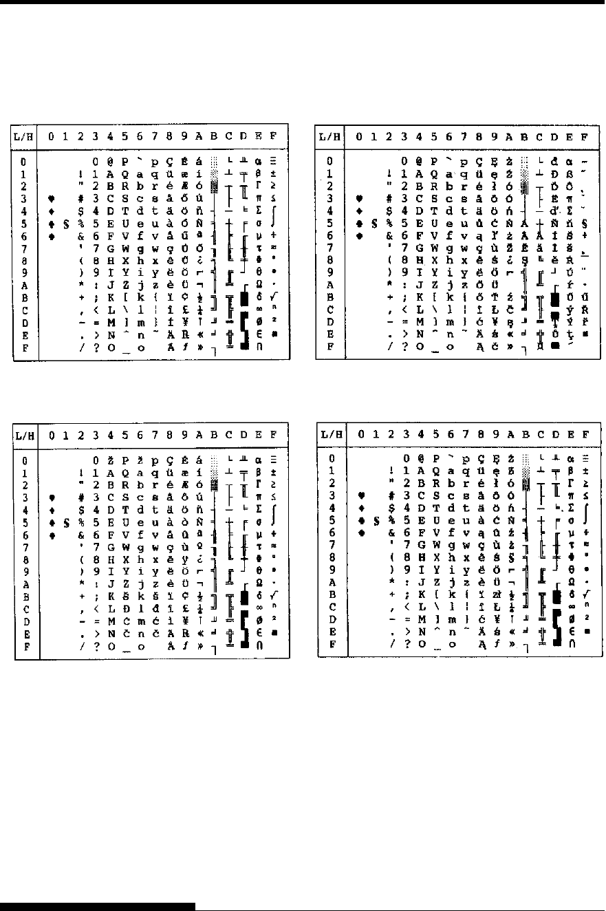
CHARACTER SETS
User's Manual E-7
HUNGARY/HUNG-T (Hungarian) POLISH/POLSH-T (Polish)
SLOV/SLOV-T (Slovenian) MAZOWIA/MAZOW-T (Mazowian)
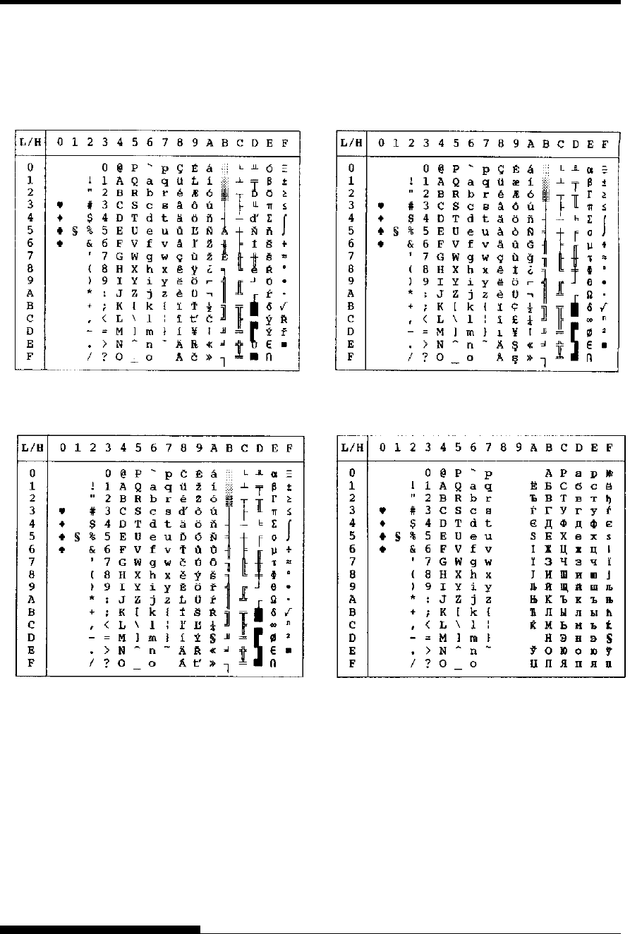
CHARACTER SETS
E-8 User's Manual
LATIN2/LATN2-T (Latin2) TURKY/TURKY-T (Turkish)
KAMENIC/KAMEN-T (Kamenicky) CYRILIC (Cyrillic)
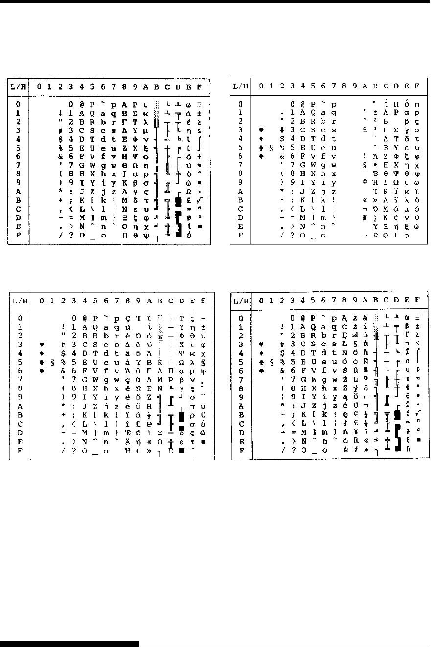
CHARACTER SETS
User's Manual E-9
IBM437 (IBM 437) ELOT928 (ELOT 928)
IBM851 (IBM 851) PG-DHN (Code Page DHN)
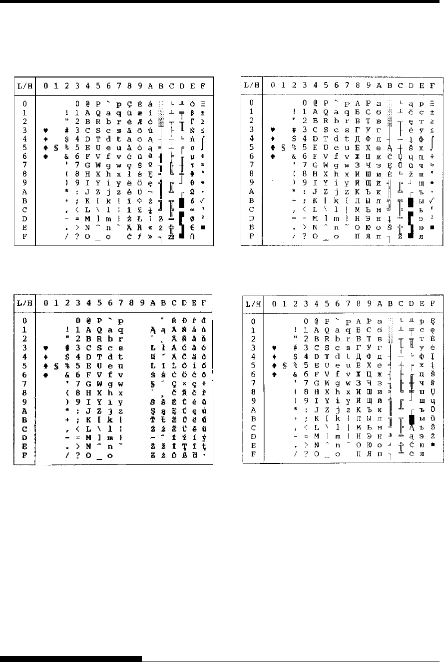
CHARACTER SETS
E-10 User's Manual
LATIN-P (Latin Polish) LITHUA1 (Lithuanian 1)
ISO-LTN (ISO Latin) LITHUA2 (Lithuanian 2)
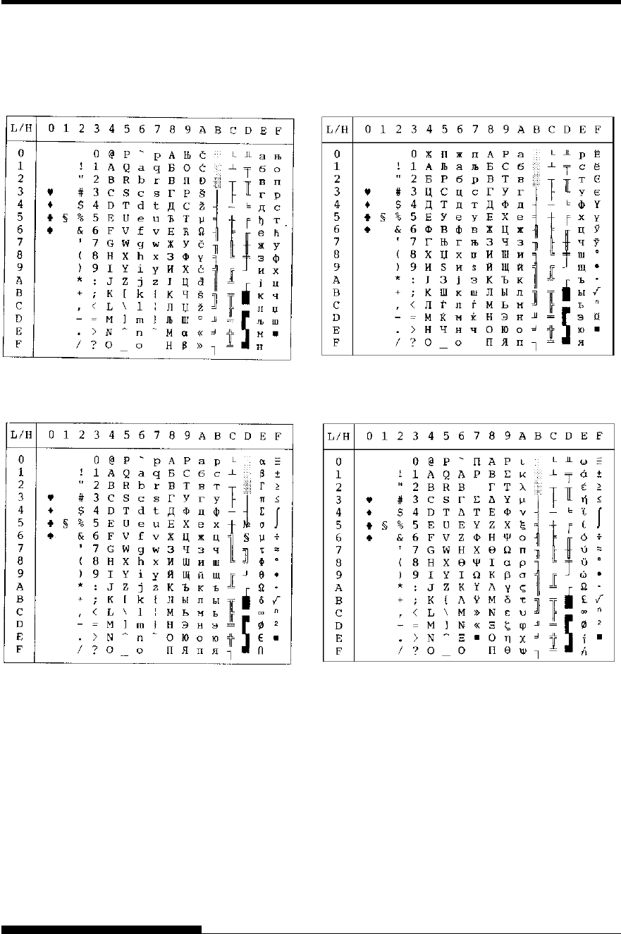
CHARACTER SETS
User's Manual E-11
MACEDON (Macedonian) PG-MAC
MIK ELOT 927
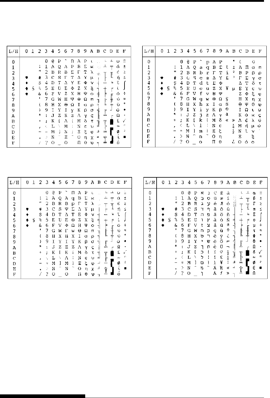
CHARACTER SETS
E-12 User's Manual
ABG DEC GR
ABY HBR-OLD
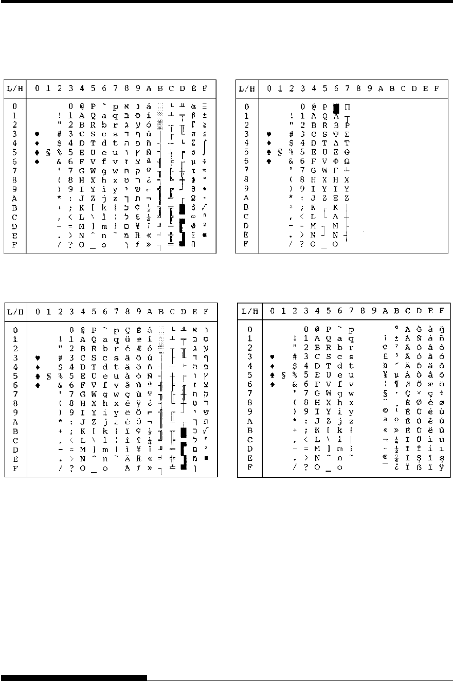
CHARACTER SETS
User's Manual E-13
PAGE 862 (Code Page 862) GREEK 11
HBR-DEC ISO-TUK
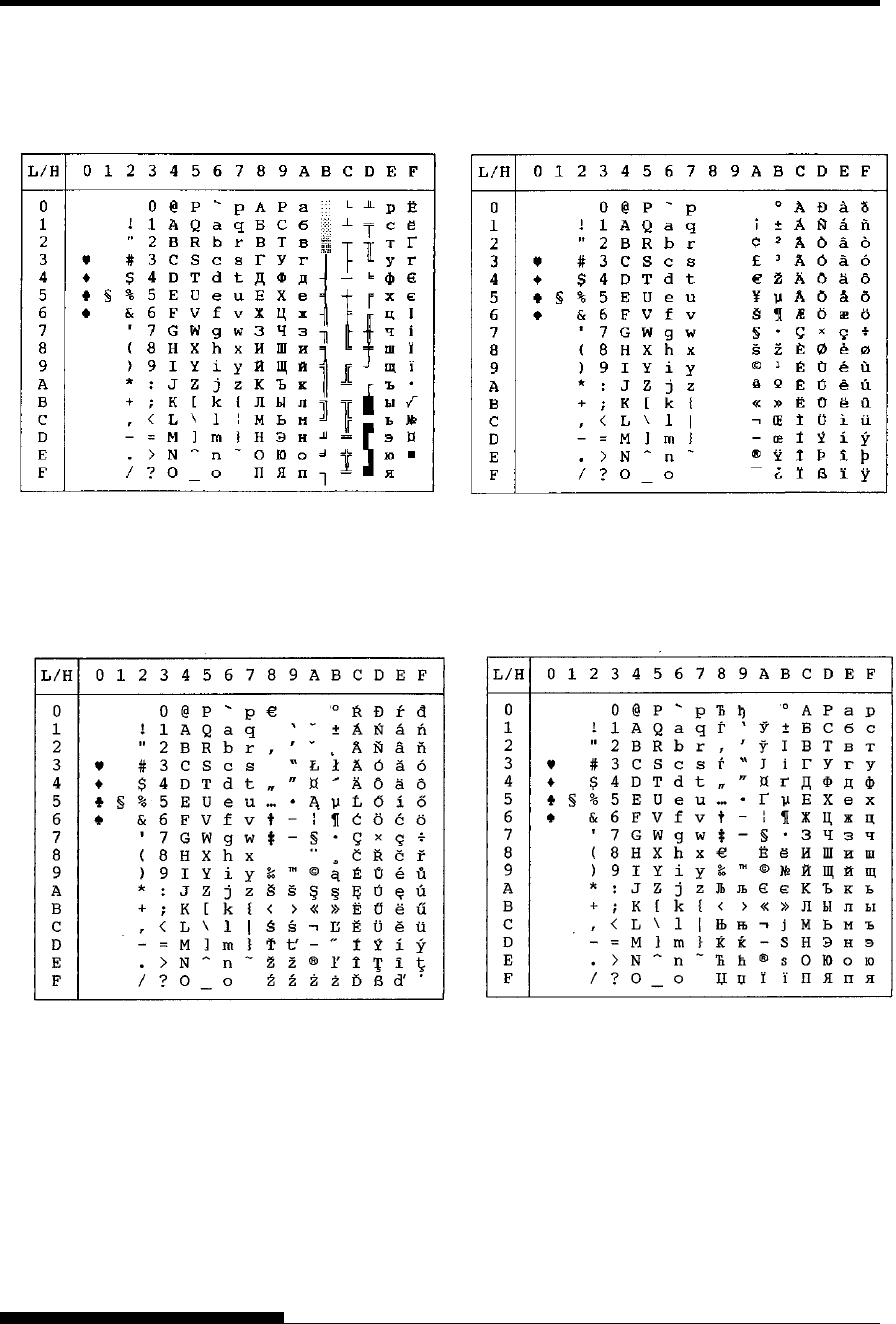
CHARACTER SETS
E-14 User's Manual
RUSCII LATIN-9
WCP1250 (Windows – 1250)
WCP1251 (Windows – 1251)
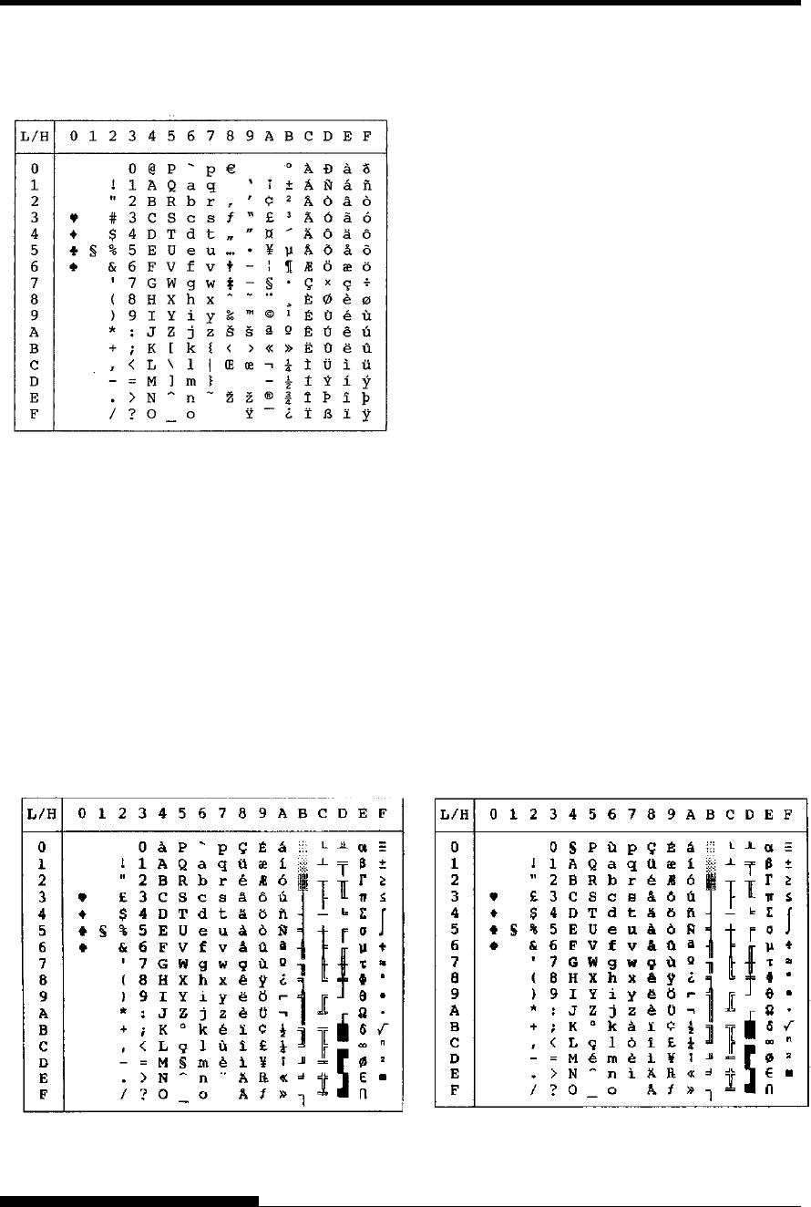
CHARACTER SETS
User's Manual E-15
The following character sets differ from those of Code Page 437 (USA),
available in the DPL24C PLUS command set and the IBM Proprinter
XL24E emulation.
NATIONAL
CHARACTER SETS
(DPL24C PLUS AND
IBM XL24E
EMULATION)
FRENCH (French) ITALIAN (Italian)
WCP1252 (Windows – 1252)
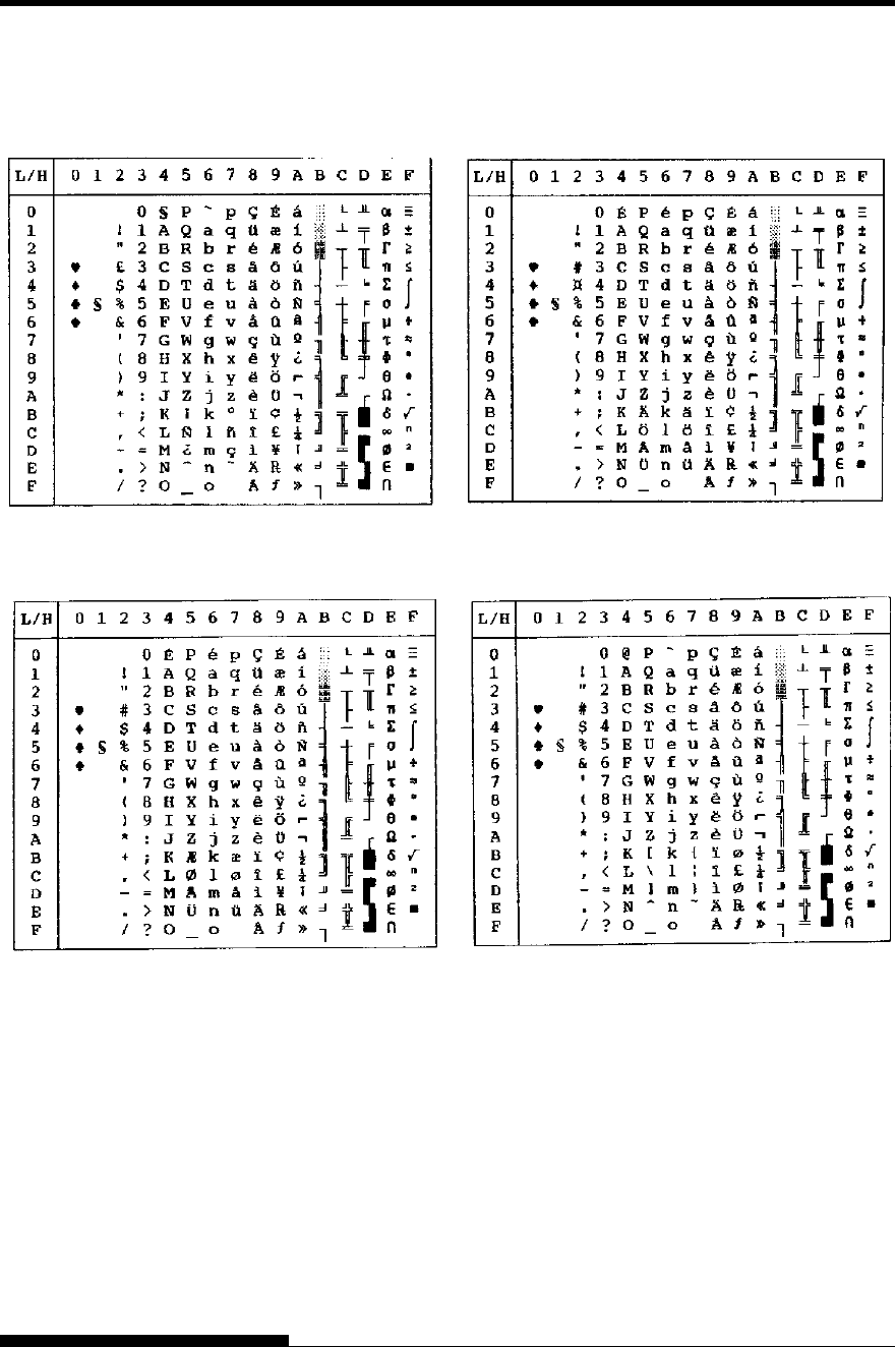
CHARACTER SETS
E-16 User's Manual
SPANISH (Spanish) FINNISH (Finnish)
DANISH1/NORWEGN (Danish1/Norwegian) DANISH2 (Danish2)
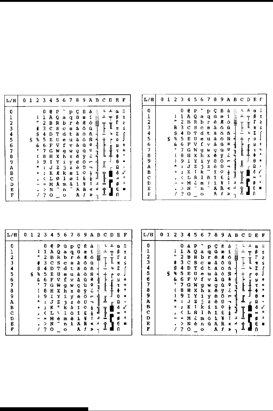
CHARACTER SETS
User's Manual E-17
The following character sets differ from the graphics character sets
available in the Epson ESC/P2 emulation.
NATIONAL
CHARACTER SETS
(ESC/P2
EMULATION)
DANISH1 (Danish1) SPANSH1 (Spanish1)
ITALIAN (Italian) SPANSH2 (Spanish2)
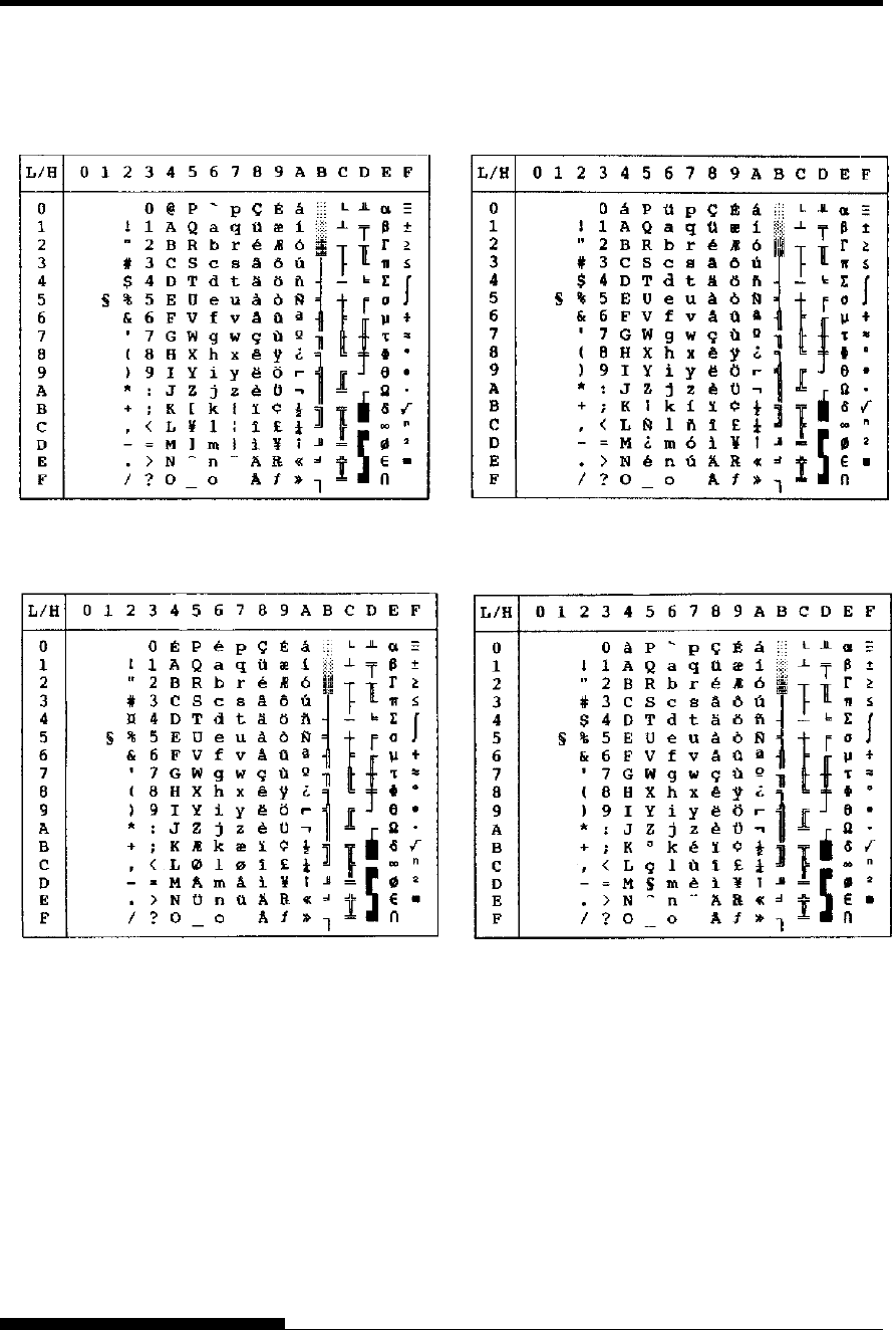
CHARACTER SETS
E-18 User's Manual
JAPAN (Japanese) LATIN A (Latin American)
NORWEGN (Norwegian) FRENCH (French)
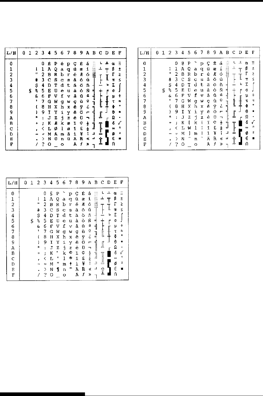
CHARACTER SETS
User's Manual E-19
DANISH2 (Danish2) KOREA
LEGAL
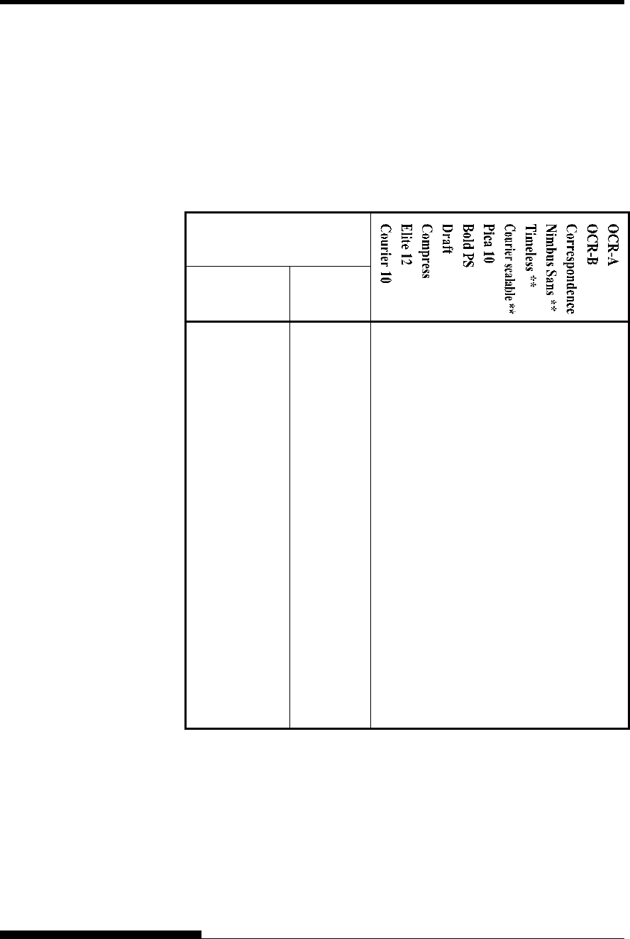
CHARACTER SETS
E-20 User's Manual
In all emulations, this printer supports 52 national character sets for
characters and symbols specific to different languages. Some national
character sets, however, do not have some characters and symbols and
may not be usable, depending on resident fonts. The following tables
show which of the resident fonts are supported for each national
character set:
Resident font
National
character set Name in
setup menu
USA * USA √√√√√√√√ √ √ √ √
United Kingdom UK √√√√√√√√ √ √ √
German GERMAN
√√√√√√√√ √ √ √
Swedish SWEDISH
√√√√√√√√ √ √ √
ISO 8859-1 ISO8859 √√√√√√√√ √ √ √
ECMA94 ECMA94
√√√√√√√√ √ √ √
Code Page 437* PAGE437 √√√√√√√√ √ √ √ √
Code Page 850 PAGE850 √√√√√√√√ √ √ √
Code Page 852 PAGE852 √√√√√√√√ √ √
Code two-pass PAGE852-T √√√√√√√√ √ √
Code Page 855 PAGE855 √√√ √ √ √ √
Code Page 860 PAGE860 √√√√√√√√ √ √ √
Code Page 863 PAGE863 √√√√√√√√ √ √ √
Code Page 865 PAGE865 √√√√√√√√ √ √ √
Code Page 866 PAGE866 √√√ √ √ √ √
(Continued on the next page)
* USA is the same as Code Page 437.
** Upright, italic, and bold available
√ : Supported
NATIONAL
CHARACTER SETS
AND SUPPORTED
RESIDENT FONTS
(ALL EMULATIONS)
CHARACTER SETS
User's Manual E-21
Resident font
National
character set Name in
setup menu
Hungarian HUNGARY √ √ √ √ √ √ √ √ √ √
Hungarian two-
pass
HUNG-T √ √ √ √ √ √ √ √ √ √
Slovenian SLOV
√ √ √ √ √ √ √ √ √ √ √
Slovenian two-
pass
SLOV-T √ √ √ √ √ √ √ √ √ √
Polish POLISH
√ √ √ √ √ √ √ √ √ √
Polish two-pass POLISH-T √ √ √ √ √ √ √ √ √ √
Mazowian MAZOWIA √ √ √ √ √ √ √ √ √ √
Mazowian two-
pass MAZOW-
T
√ √ √ √ √ √ √ √ √ √
Latin 2 LATIN2 √ √ √ √ √ √ √ √ √ √
Latin 2 two-pass LATIN2-T √ √ √ √ √ √ √ √ √ √
Kamenicky KAMENIC
√ √ √ √ √ √ √ √ √ √
Kamenicky two-
pass
KAMEN-T √ √ √ √ √ √ √ √ √ √
Turkish TURKY
√ √ √ √ √ √ √ √ √ √
Turkish two-pass TURKY-T √ √ √ √ √ √ √ √ √ √
Cyrillic CYRILIC
√ √ √ √ √ √ √
IBM 437 IBM437 √ √ √ √ √ √ √
IBM 851 IBM851 √ √ √ √ √ √ √
ELOT 928 ELOT928 √ √ √ √ √ √ √
Code Page DHN PG-DHN √ √ √ √ √ √ √ √ √ √
Latin Polish LATIN-P √ √ √ √ √ √ √ √ √ √
ISO Latin ISO-LTN √ √ √ √ √ √ √ √ √ √
(Continued on the next page)
** Upright, italic, and bold available
√ : Supported
CHARACTER SETS
E-22 User's Manual
Resident font
National
character set Name in
setup menu
Lithuanian 1 LITHUA1 √√√√ √ √ √
Lithuanian 2 LITHUA2 √√√√ √ √ √
MIK MIK
√√√√ √ √ √
Macedonian MACEDON √√√√ √ √ √
ABG ABG
√√√√ √ √ √
ABY ABY
√√√√ √ √ √
DEC Greek DEC GR √√√√ √ √ √
ELOT 927 ELOT 927 √√√√ √ √ √
GREEK 11 GREEK 11 √√√√ √ √ √
Code Page 862 PG 862 √√√√√√
Hebrew DEC HBR-DEC √√√√√√
Hebrew Old HBR-OLD √√√√√√
Code Page MAC PG-MAC √√√√ √ √ √
ISO Turkish ISO-TUK √√√√√√√√ √ √
RUSCII RUSCII
√√√√√√√√ √
ISO8859-15 LATIN-9
√√√√√√√√ √ √
Windows Code
Page 1250
WCP1250 √√√√√√ √ √
Windows Code
Page 1251
WCP1251 √√√√√√ √ √
Windows Code
Page 1252
WCP1252 √√√√√√ √ √
** Upright, italic, and bold available
√ : Supported
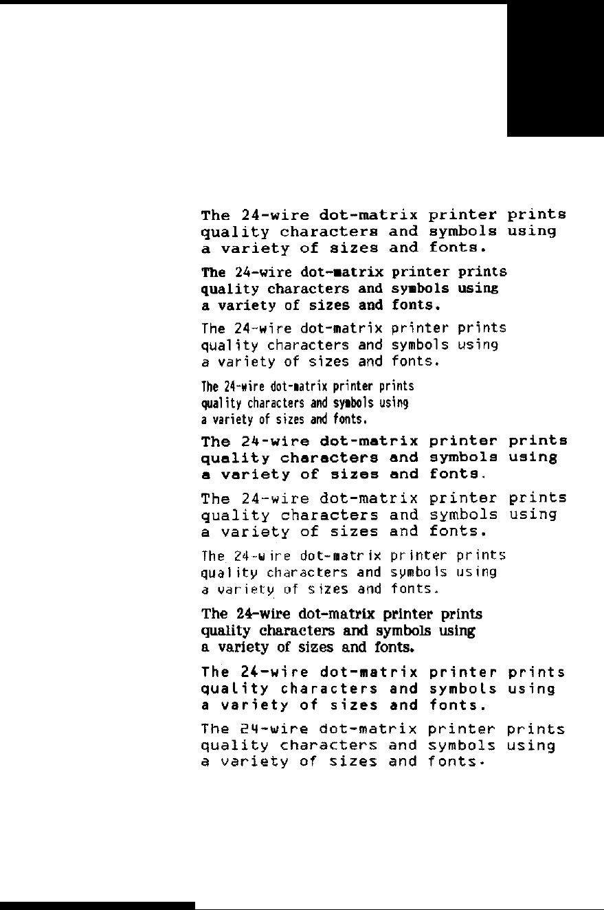
User's Manual F-1
F
APPENDIX F RESIDENT FONTS
RESIDENT FONTS
This appendix provides print samples of
the printer's nineteen resident fonts.
COURIER 10
PRESTIGE ELITE 12
DRAFT 12
COMPRESSED
PICA 10
CORRESPONDENCE 10
HIGH-SPEED DRAFT 12
BOLDFACE PS
OCR-B 10
OCR-A 10
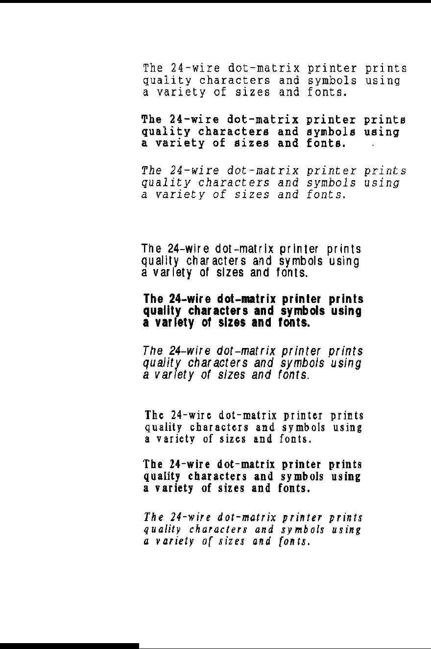
RESIDENT FONTS
F-2 User's Manual
COURIER (SCALABLE)
Normal
Bold
Italic
Normal
Bold
Italic
Normal
Bold
Italic
NIMBUS SANS ®
(SCALABLE)
TIMELESS (SCALABLE)

User's Manual IN-1
INDEX
INDEX
A
Adjustments
left margin.......................3-10, 3-12, 3-16, 5-18
left print start position.................................5-35
top-of-form .....................3-22, 5-19, 5-32, 5-33
paper thickness..............................................3-8
AMOUNT ........................................................5-49
ATTRIB ...........................................................5-17
B
Bidirectional printing ............................. 5-28, 5-56
Boldface ..............................................1-1, 4-5, F-1
BUFFER.................................QR-2, 4-1, 5-28, B-1
BUZZER ..........................................................5-28
C
Cables
LAN.....................................1-3, 2-22, 8-1, A-1
parallel interface ............................... 2-21, 5-29
serial interface.................2-21, 5-12, 5-29, 5-30
USB ........................................ 2-22, 5-29, D-11
Centronics....................................... 2-21, 5-29, D-1
Character................................5-15, 5-16, 5-20, E-1
Cleaning .............................................................6-1
Continuous forms
loading .............................................. 3-16, 3-19
placement....................................................3-15
tearing off ...................................................3-20
unloading ....................................................3-19
Control panel...................QR-1, 2-14, 3-2, 4-1, 6-8
Cut sheet feeder
installing ....................................... 3-6, 8-1, A-1
loading ........................................................3-12
D
Default.................................................... 5-10, 5-51
Demo pattern....................................................2-20
Diagnostic functions................................. 5-52, 7-9
Download ..........................................B-1, B-4, C-8
DPL24C PLUS ................................................ 5-14
DRAFT.................................................... 5-15, B-2
E
Eject.......................................................QR-2, 3-14
Emulation ............................................... 2-23, 5-14
Envelope.......................................................... 3-23
Epson ESC/P2 .................................4-5, 5-14, 5-62
F
Feeding paper
form feed.................................. QR-2, 3-3, 3-22
line feed.................................... QR-2, 3-3, 3-22
Font........................................................... 4-5, 5-14
Function............................................................. 5-4
H
HEX-DUMP......................................5-4, 5-54, 7-9
I
IBM Proprinter XL24E..................2-23, 5-14, 5-62
Interface..........................................2-21, 5-29, D-1
L
Label................................................................ 3-23
LAN interface...............................2-23, 5-29, D-12
LF/FF.......................................................QR-2, 3-3
Line feed................................ QR-2, 3-3, 3-22, B-5
Line spacing ................................... 5-18, 5-36, B-4
LIST............................................................ 5-4, 5-8
LOAD......................................................QR-2, 3-3
Loading............................................3-9, 3-12, 3-16
Lubrication ........................................................ 6-1

INDEX
IN-2 User's Manual
M
Maintenance....................................................... 6-1
Margin ............................................................. 5-32
Menu.......................................QR-2, 2-26, 4-4, 5-4
Multipart paper ..................................................B-8
N
Number of copies....................................... 3-9, B-3
O
ONLINE ........................................ QR-2, 3-3, 5-41
Order number.................................................... A-1
P
Page ........................................................ 2-17, 2-27
PAPER OUT.............................. 4-6, 5-27, 7-6, 7-8
Paper path ........................................ QR-2, 3-3, 3-5
Power..................................... QR-2, 2-15, 7-6, B-1
Print area............................................................B-6
Print head........................................................... 6-6
Printer Driver................................................... 2-28
Q
QUALITY ................................................ 5-15, 7-1
Quick Reference .............................................QR-1
R
Removing printed pages .................................... 4-8
Replacing ribbon cartridge ................................ 6-3
Resume printing...................................... QR-2, 4-6
Ribbon cartridge .................................2-8, 6-1, A-1
Ribbon subcassette ........................................... A-1
RS-232C .......................................................... 5-29
S
Self-test............................................2-17, 5-4, 5-52
Serial interface................................2-21, 2-28, D-7
Setup mode ........................................................ 5-1
Single sheet
loading.......................................................... 3-9
Single sheets................................................ B-6
ejecting....................................................... 3-14
Software............................................................. 4-3
Specifications.................................................... B-1
Supplies............................................................. A-1
T
TEAR OFF..................................... QR-2, 3-3, 3-20
Testing printer
offline......................................................... 2-16
online.......................................................... 2-27
Top margin....................................................... 5-19
U
Unidirectional printing............................. 5-28, B-2
Unpacking.......................................................... 2-2
USB interface................................2-22, 5-29, D-11
V
V-ALMNT function......................................... 5-56
Vertical character displacement....................... 5-56
W
WIDTH............................................ 5-24, B-1, B-2
Please send your comments on this manual or on Fujitsu products to the
following addresses:
North American Contact:
FUJITSU CANADA INC.
6975 Creditview Road, Unit 1,
Mississauga,
Ontario L5N 8E9, CANADA
Phone: (1-905) 286-9666
Fax: (1-905) 286-5977
European Contact:
FUJITSU EUROPE LTD.
Hayes Park Central,
Hayes End Road,
Hayes,
Middlesex UB4 8FE, U.K.
Phone:(44-20) 8573-4444
Fax:(44-20) 8573-2643
FUJITSU DEUTSCHLAND GmbH
Frankfurter Ring 211,
80807 München, Germany
Phone:(49-89) 32-378-0
Fax:(49-89) 32-378-100
FUJITSU ITALIA S.p.A.
Via Nazario Sauro, 38
20099 Sesto S. Giovanni (MI), Italy
Phone: (39-02) 26294-1,
Fax: (39-02) 26294-201
FUJITSU ESPAÑA, S.A.
Camino Cerro de los Gamos, 1-28224
Pozuelo de Alarcón, Madrid, Spain
Phone: (34-91)784-9000,
Fax: (34-91)784-9266
Australian Contact:
FUJITSU AUSTRALIA LTD.
Fujitsu House 2 Julius Avenue
North Ryde N.S.W. 2113, Australia
Phone:(61-2) 9776-4555
Fax:(61-2) 9776-4556
Asian Contact:
FUJITSU HONG KONG LTD.
10F., Lincoln House, 979 King's Road, Taikoo
Place,
Island East, Hong Kong
Phone:(852) 2827-5780
Fax:(852) 2827-4724
FUJITSU TAIWAN LTD.
19th FL., No. 39, 1 Sec. Chung Hwa Rd.,
Taipei, Taiwan R.O.C.
Phone: (886-2) 2311-2255
Fax: (886-2) 2311-2277
FUJITSU SYSTEMS BUSINESS (THAILAND) LTD.
Exchange Tower, 22nd-23rd Fl, 388 Sukhumvit Road,
Kwaeng Klongtoey, Khet Klongtoey,
Bangkok 10110, Thailand
Phone:(66-2)302-1500
Fax:(66-2)302-1555
FUJITSU ASIA PTE. LTD.
20 Science Park Road #03-01, Tele Tech Park II
Singapore 117674
Phone: (65)6512-7555
Fax : (65)6512-7502
FUJITSU PHILIPPINES, INC.
2nd Fl., United Life Bldg., A.Arnaiz,
Legaspi Village, Makati, Metro Manila, Philippines
Phone: (63-2) 812-4001
Fax: (63-2) 817-7576
FUJITSU (MALAYSIA) SDN. BHD.
Level 1 & 2, 3505, Jatan Teknokrat 5,
63000 Cyberjaya, Selangor Darul Ehsan, MALAYSIA
Tel:(60-3)8318-3700
Fax:(60-3)8318-8700
PT FUJITSU INDONESIA
Kyoei Prince Building 10th Floor.
Jl. Jend. Sudirman Kav 3 - 4
Jakarta 10220, Indonesia
Phone: (62-21) 570-9330
Fax: (62-21) 573-5150
Manufacturer contact:
FUJITSU ISOTEC LIMITED
Printer Business Division
135, Higashinozaki, Hobara-machi, Date-shi, Fukushima
960-0695, JAPAN
Phone: (81-24)574-2236,
Fax: (81-24)574-2382
URL http://jp.fujitsu.com/group/fit/en/
Contact Email fit-gsm@cs.jp.fujitsu.com
FUJITSU OFFICES

C147-E051-01EN