Fujitsu Isotec 018M33325A Dot Matrix Printer User Manual 2 of 2
Fujitsu Isotec Limited Dot Matrix Printer 2 of 2
UserManual.wiki
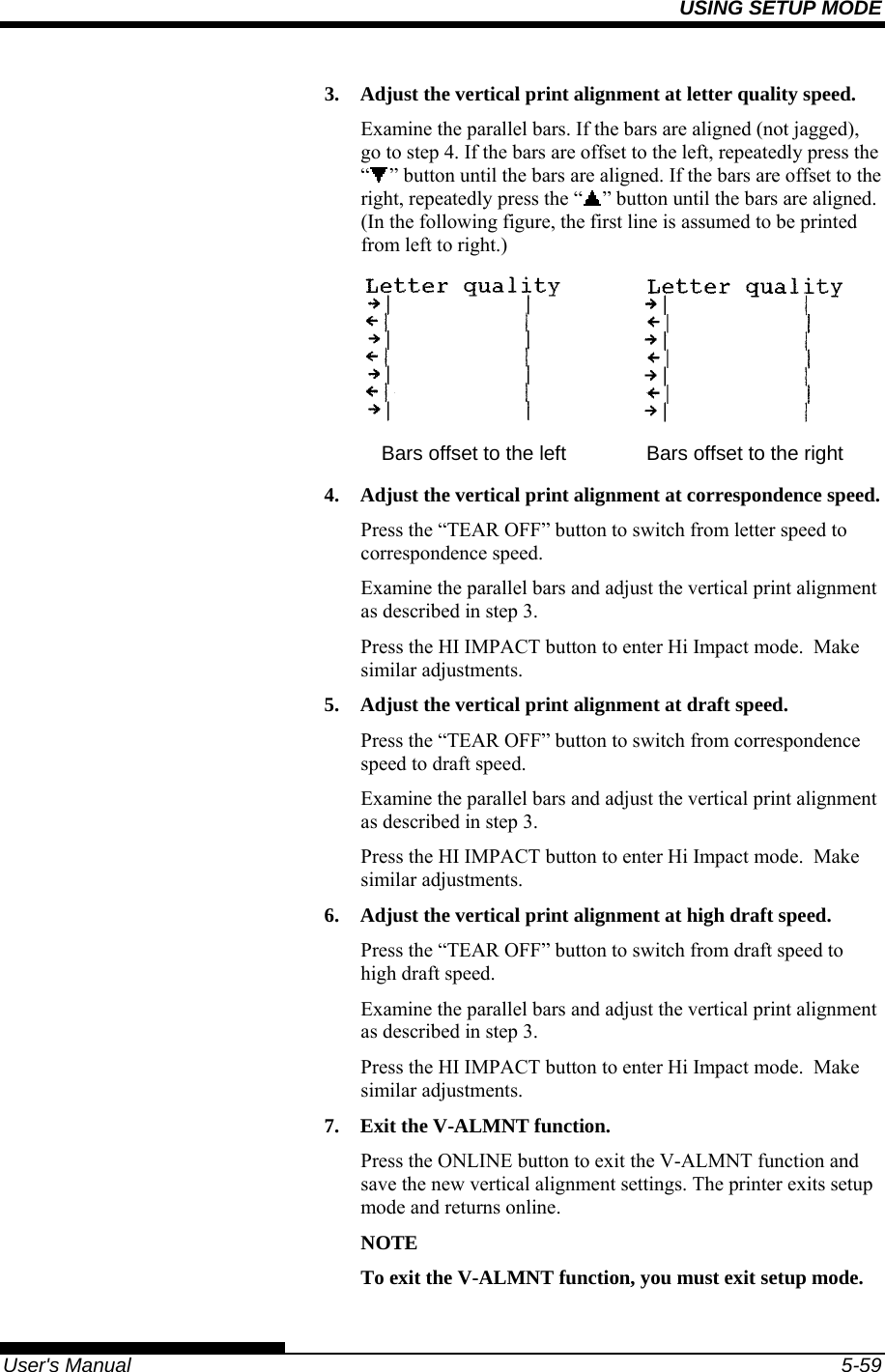
>
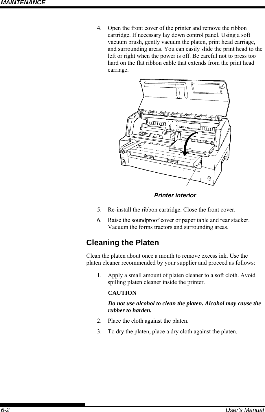
Fujitsu Isotec
>
018M33325A User Manual
>
User manual 2 of 2
Contents
1.
User manual 1 of 2
2.
User manual 2 of 2
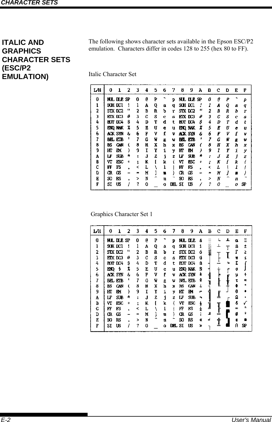
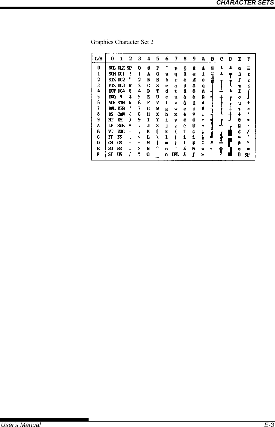
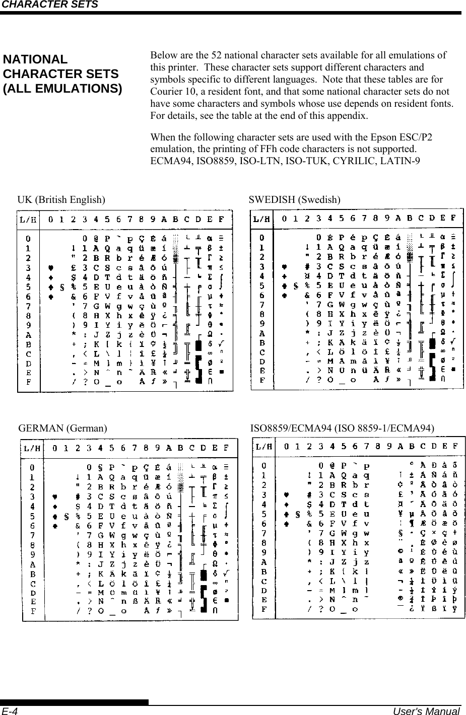
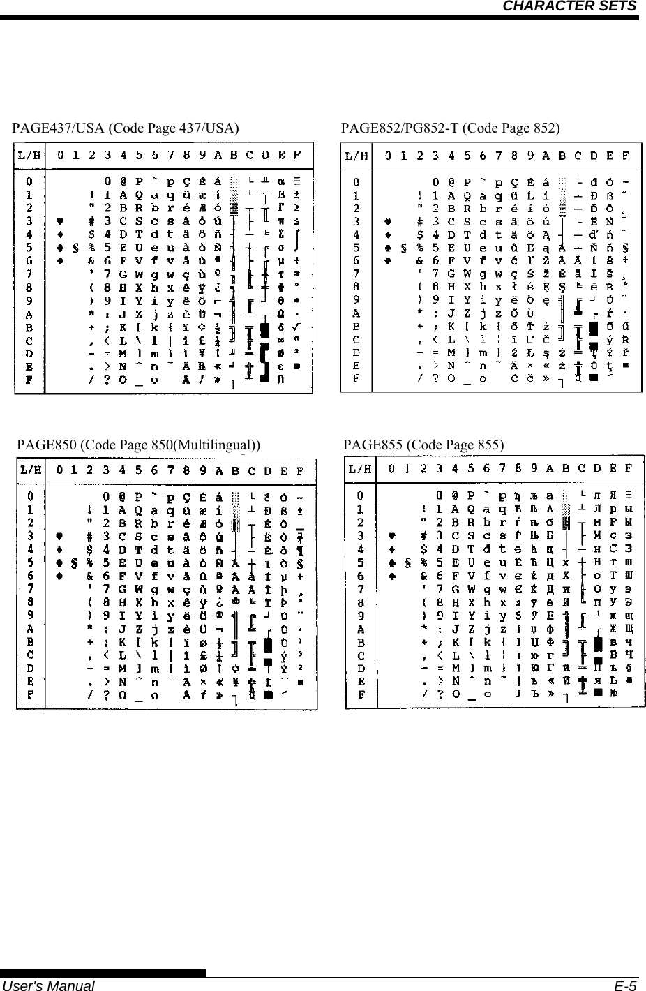
User manual 2 of 2
Navigation menu
Upload a User Manual
Namespaces
Wiki Guide
HTML
PDF
Info
Views
User Manual
Discussion / Help
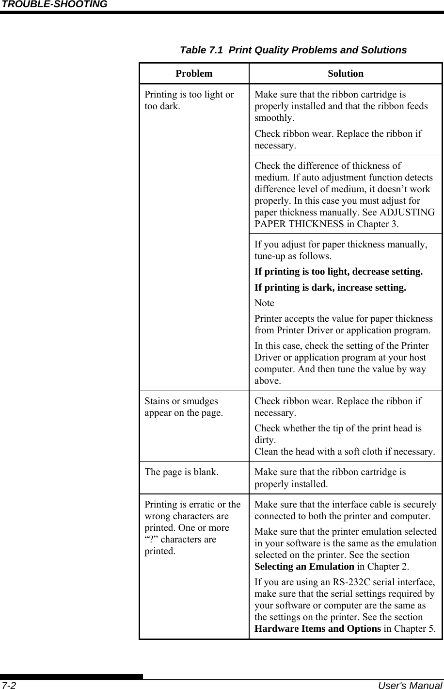
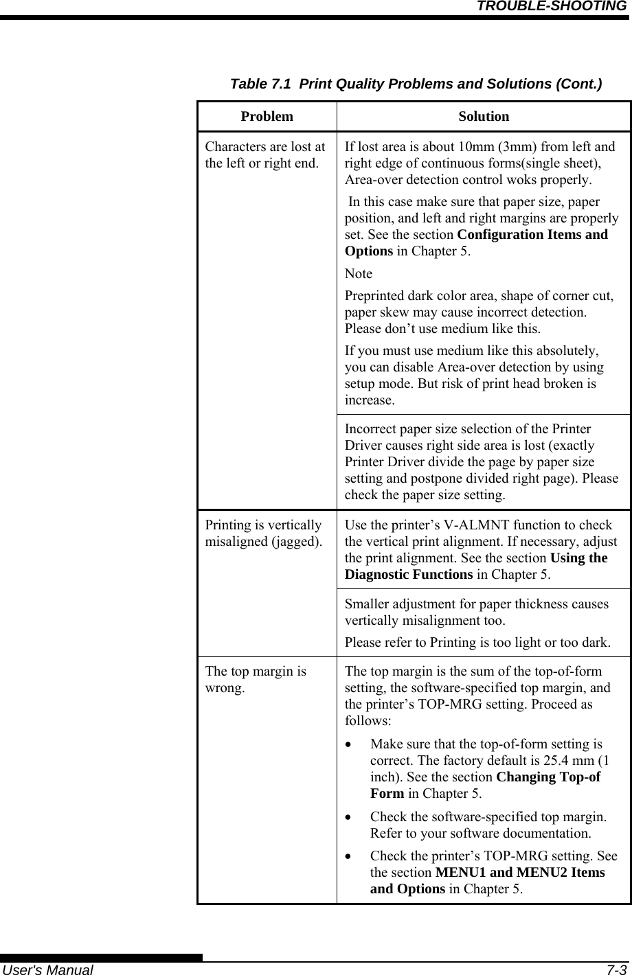
Navigation

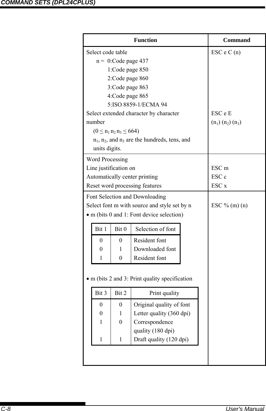
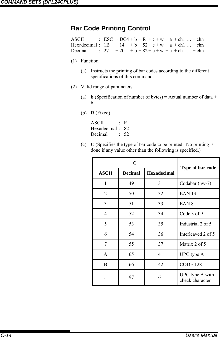
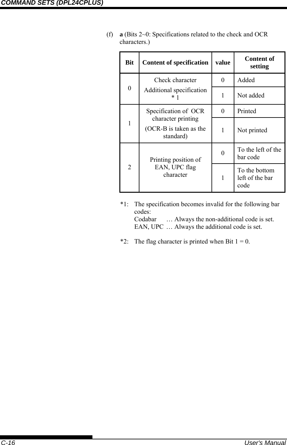
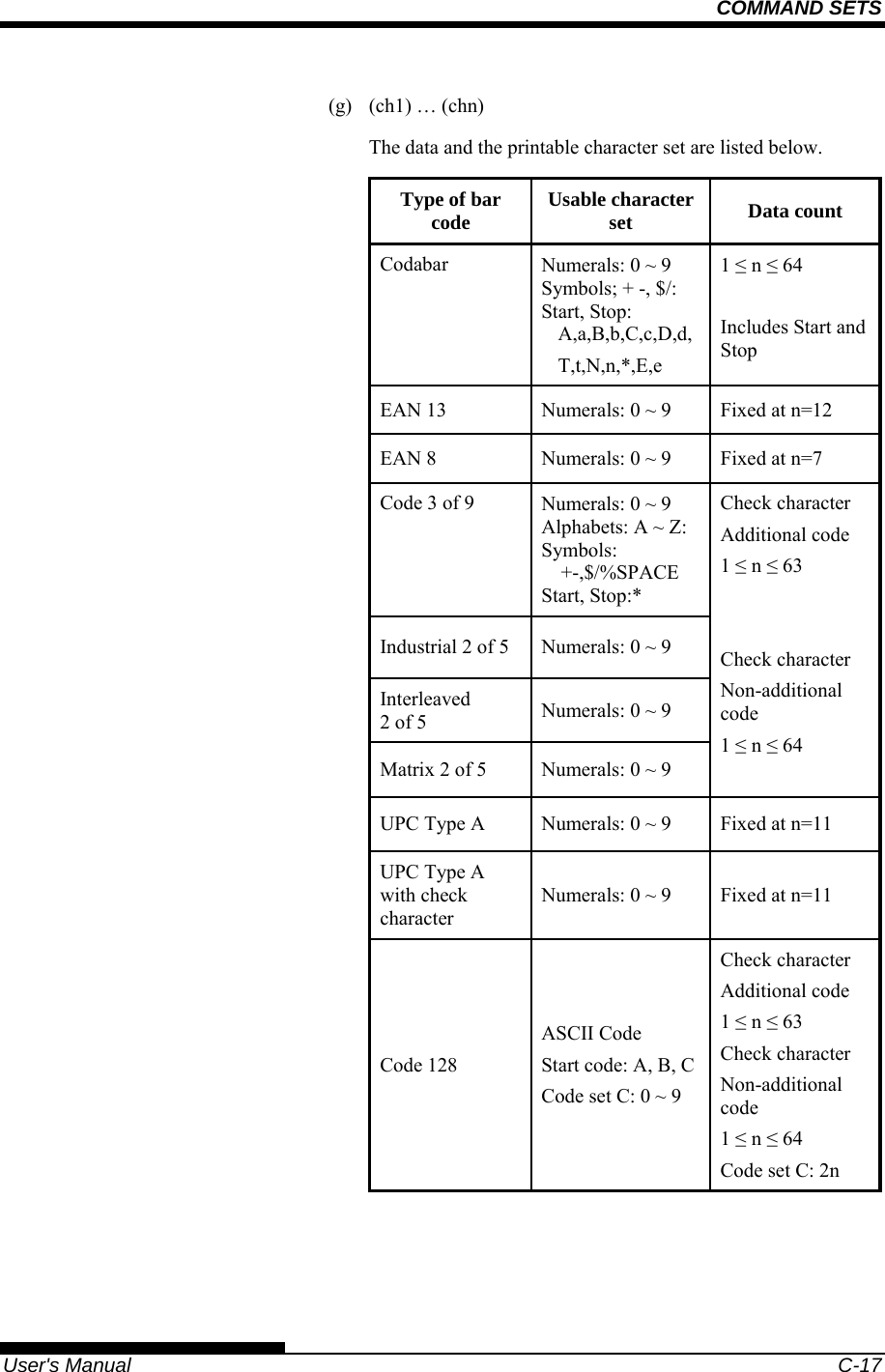
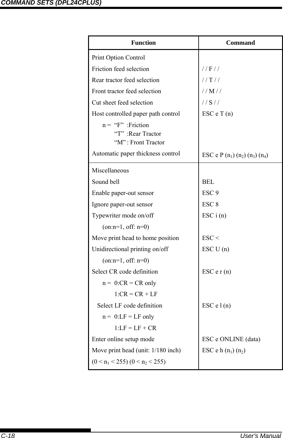
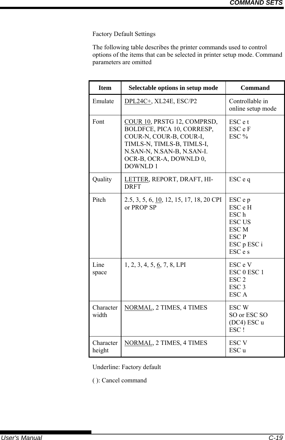
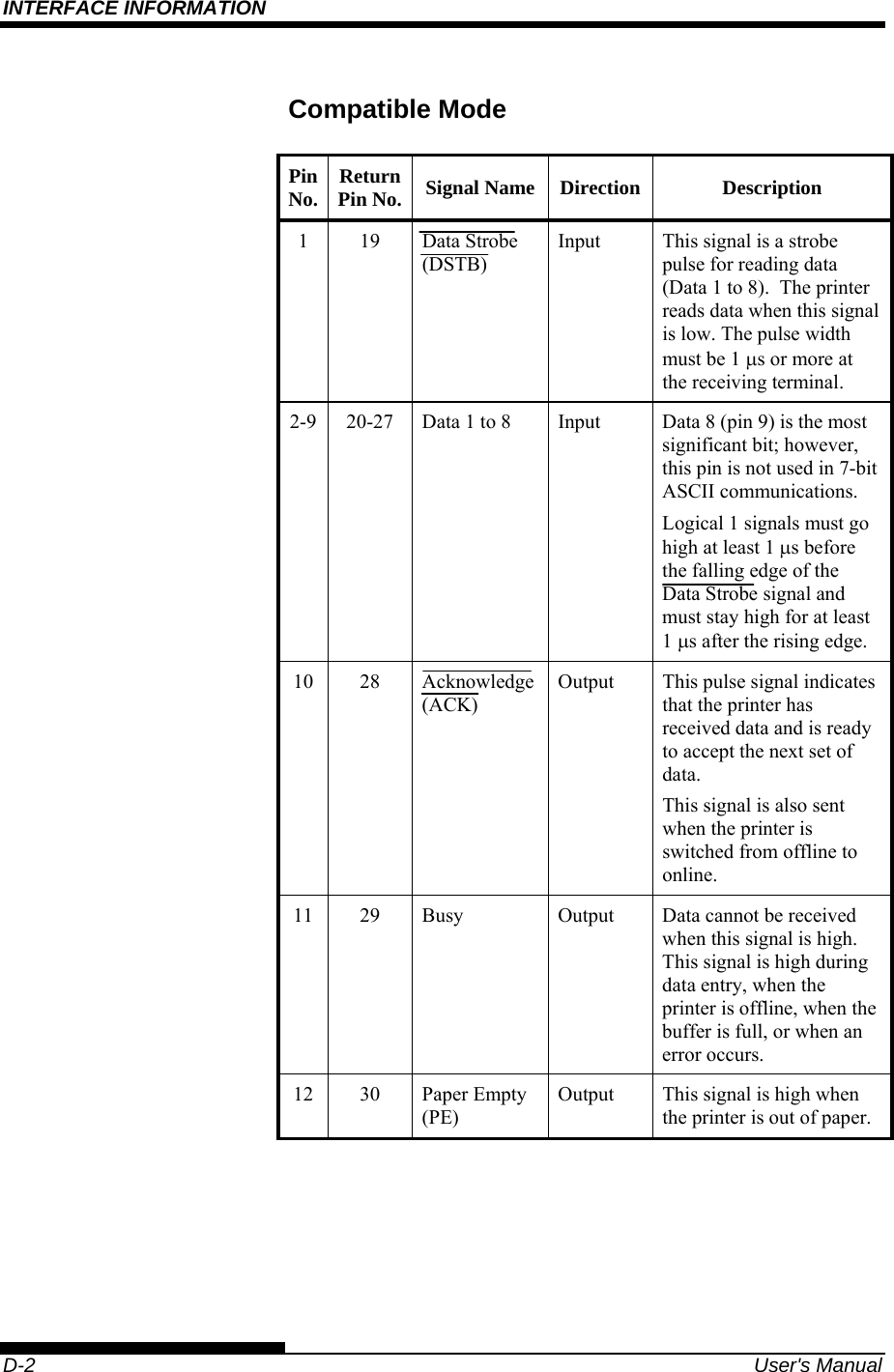
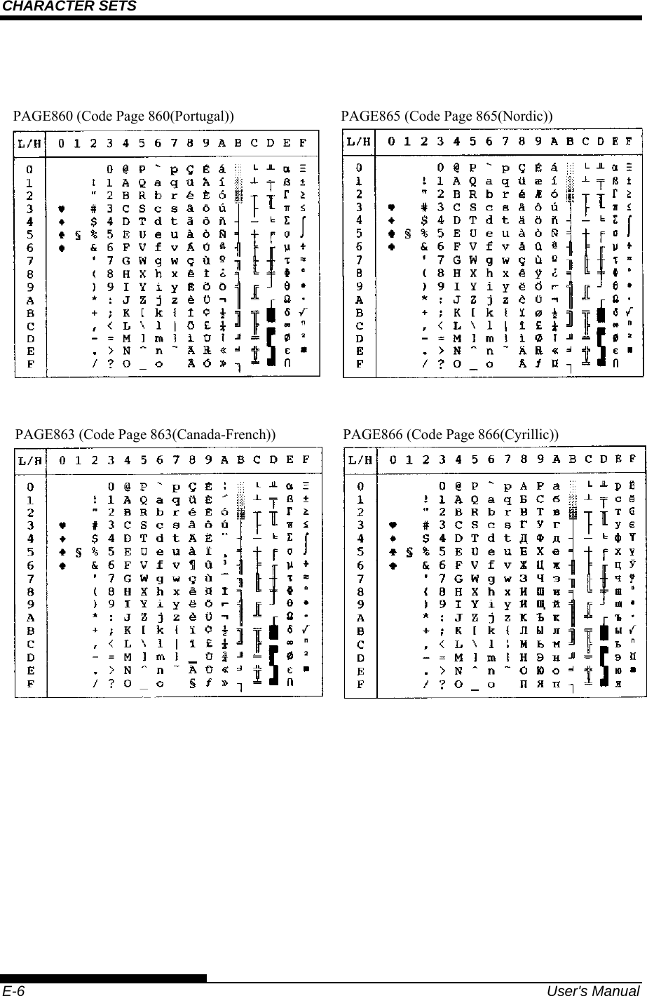
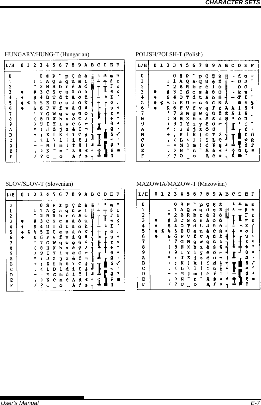
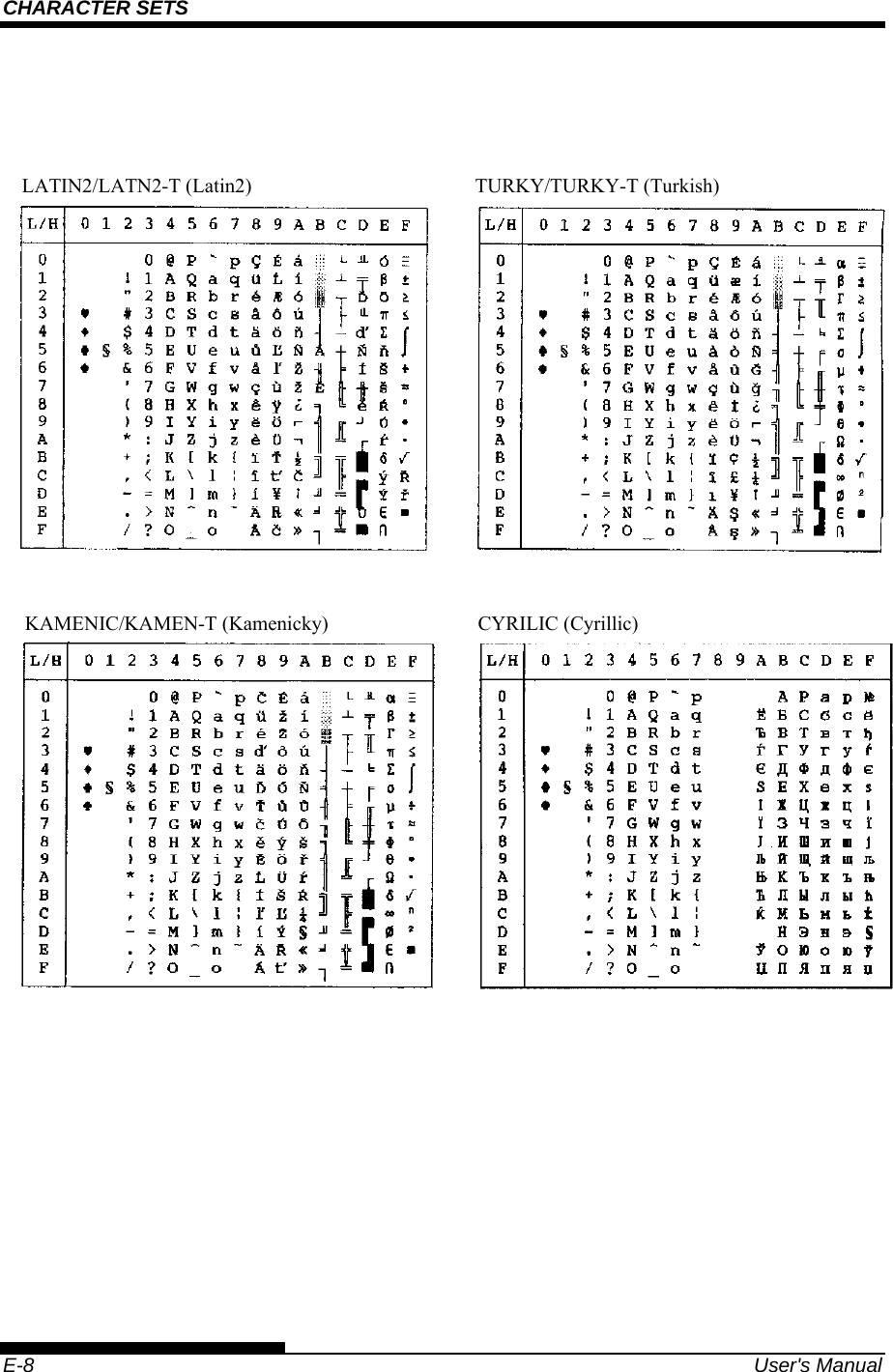
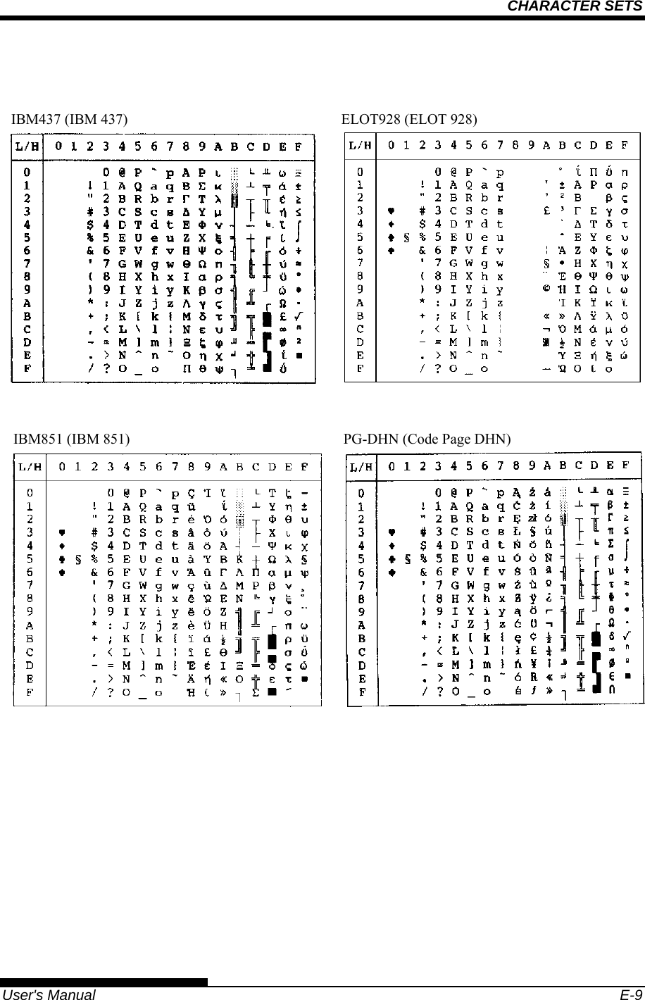
![COMMAND SETS User's Manual C-15 (d) w (Specify the width of the narrow bar of the bar code to be printed in units of 1/1440.) Specify the “Logical value” to be printed (in units of 1/1440). Actual printing: The printer prints with the width given in the following table in units of 1/180 inches. w Width of narrow bar 1 ~ 19 2 Dots (2/180 inches) 20 ~ 27 3 Dots (3/180 inches) 28 ~ 4 Dots (4/180 inches) (e) h (Specify the height of the bar code to be printed in units of 1/1440 taking the narrow bar width as the reference.) Height of bar code = (parameter w) × (parameter h) [in units of 1/1440] Height of bar code ≤ 11 Inches Actual printing: The printing is done with the following initial values if the bar code height is less than or equal to 24 dots taking 1 dot equal to 1/180 inches of the printing unit of the printer. The following values are the standard heights for the respective bar code standards. Enter the value so that the height is ≤ 23/180 if the standard is correct. Narrow bar width EAN 13/UCP-A EAN 8 Others 2 Dots (16/1440) 162 Dots (1296/1440)130 Dots (1040/1040) 108 Dots (864/1440) 3 Dots (24/1440) 234 Dots (1872/1440)187 Dots (1496/1040) 135 Dots (1080/1440)4 Dots (32/1440) 312 Dots (2496/1440)249 Dots (1992/1040) 162 Dots (1296/1440) Figures in parentheses ( ) are values converted to units of 1/1440. ..](https://usermanual.wiki/Fujitsu-Isotec/018M33325A.User-manual-2-of-2/User-Guide-897802-Page-83.png)