Fujitsu 2012-001-SNB Communication Module User Manual ver1 3x
Fujitsu Limited Communication Module ver1 3x
Fujitsu >
User manual

User manual
1/10
User manual
User manualUser manual
User manual
Ver 1.3

User manual
2/10
C
CC
Change history
hange historyhange history
hange history
revision Updated date
summary
1.0 Aug 1 2012 First edition
1.1 Aug 6 2012
Modification
Page 6(DSSS/CCK->DSSS/BPSK),7(modification of consumption),
8(addition of following sentence)
This device complies with Part 15 of the FCC Rules. Operation is subject
to the following two conditions:
(1) this device may not cause harmful interference, and
(2) this device must accept any interference received, including
interference that may cause undesired operation.
1.2 August 15 2012
-Fixing of 3.1(delete comments of remarks)
- addition of 5.6 Indicating compliance with ICES-003
1.3 August 28 2012
- Fixing of 4.3

User manual
3/10
Table of contents
Table of contentsTable of contents
Table of contents
1.
Apprication ..................................................................................................................................... 4
2.
System Configuration ..................................................................................................................... 4
3.
Description of Meter (Host) ............................................................................................................ 5
3.1
Overview .................................................................................................................................... 5
3.2
Operating Range ........................................................................................................................ 5
4.
Description of Module ( Module) .................................................................................................... 6
4.1
Overview .................................................................................................................................... 6
4.2
Operating Range ........................................................................................................................ 6
4.3
Major element ............................................................................................................................ 6
4.4
Basic specification 【module】 .................................................................................................... 7
5.
Required FCC and IC statement ( Host ) ....................................................................................... 8
5.1
FCC §15.21 ................................................................................................................................ 8
5.2
FCC §15.105 .............................................................................................................................. 8
5.3
RSS-Gen §7.1.2. ........................................................................................................................ 8
5.4
RSS-Gen §7.1.3. ........................................................................................................................ 8
5.5
Indicating safe separation distance warning .............................................................................. 9
6.
Required FCC and IC statement (Module)...................................................................................10
6.1
FCC §15.21 ..............................................................................................................................10
6.2
FCC §15.105 ............................................................................................................................10
6.3
RSS-Gen §7.1.2. ......................................................................................................................10
6.4
RSS-Gen §7.1.3. ......................................................................................................................10
User manual
4/10
1. Apprication
This document shows the description of wattmeter(hereinafter called meter)and mounted
communication board(hereinafter called module).
- target meters : GE I210+ Meter FM1S / FM2S / FM12S / FM25S
- Module : Fujitsu YAA75-0402
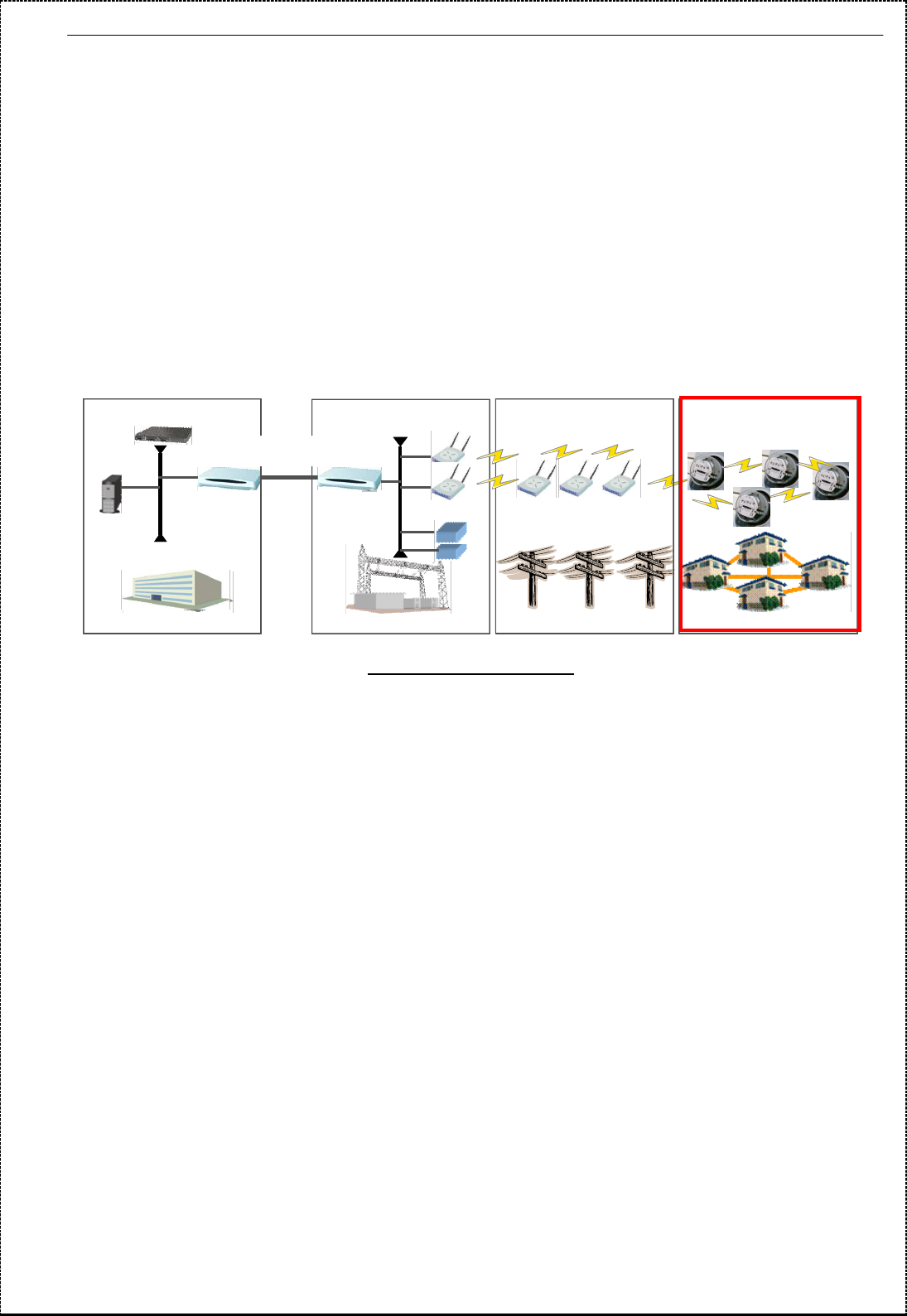
2. System Configuration
Fig2-1 is general system configuration of using meter.
Installed meters in each house is communicated to Center via Repeaters and Gateways and control
the meter-reading value etc.automatically.
Red line of Fig.2-1 is the applicable scope of this document.
Fig2-1 System configuration
Substation
Poles Houses
…..
Center
Server
-
DHCP Server
Router
Router
Fiber-opt
network
Switch
Meters
Repeaters
Gateway
User manual
5/10
3. Description of Meter (Host)
3.1 Overview
Form and overview of meter are as follows.
Category
Meter form
Remark
FM
1S
FM
2S
FM
12S
FM
25S
Input voltage
120VAC 240VAC 120VAC
or 240VAC
120VAC
or 240VAC
enclosure
Same form
Meter panel
board Same board
Meter socket
type Different type
Mouted module
Same module
meter panel
interface Same interface
AC power
cable Same cable
3.2 Operating Range
• Voltage : + - 20% (or ±20%)
• Temperature : -40°C through +85°C
• Typical Starting Watts : <=5.0 Watts (Form 2S 240V CL200)
• Typical Watts Loss : 0.7 Watts
• Typical Accuracy : Within +/- 0.2%
User manual
6/10
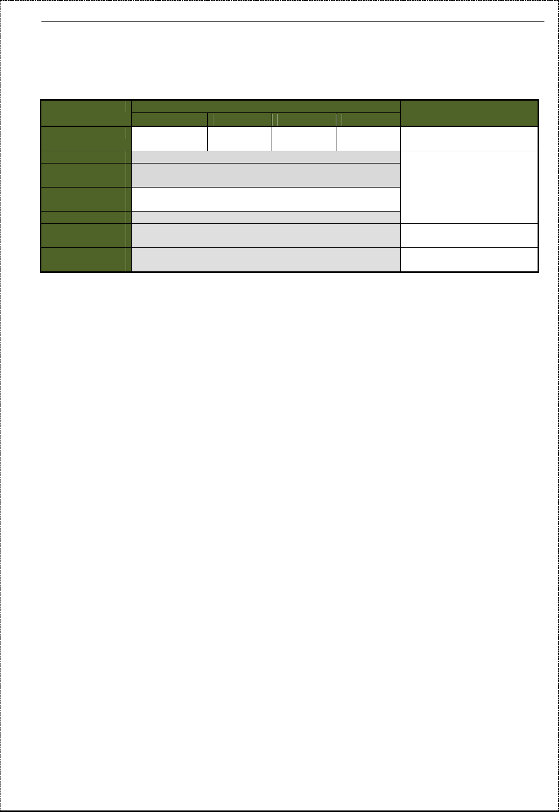
4. Description of Module ( Module)
4.1 Overview
The module mounted to each meter in paragraph 3 collects the meter-reading values etc.
with controlling Center.
4.2 Operating Range
Same as chapter 3.2.
4.3 Major element
Major elements of module are as follows.
No.
component summary remark
1
Radio element IEEE802. 11b
Transmission power:100mW
Modulation:DSSS / BPSK
Data rate :1Mbps
2
22
2 Antenna This antenna made by printed-circuit in the module.
3
Meter panel
interface
element
Communication between Meter panel.
Signals:refer to chapter 3.2
4
Power element *AC cable(with ferrite bead) is connected to
this element.
*This element steps down AC input(120V/240V) to
+3.3VDC.
5
Dispray element extinction
power off or normal operation LED(green)
blinking No operation ( start-up firmware)
lighting No operation(reset / no service)
extinction
normal LED(red)
blinking fault
lighting reset
AC cable with
ferrite bead
120/
240VAC
Meter
*Display
*Meter
information
collection
Meter
panel
module
Power
element
Radio
element
antenna
element
Meter
Socket
From electric pole
120VAC
/
240VAC
120VAC
/ 240VAC
+3.3
V
D
C
UART/
Control
signal
Meter
panel
Interface
element
User manual
7/10
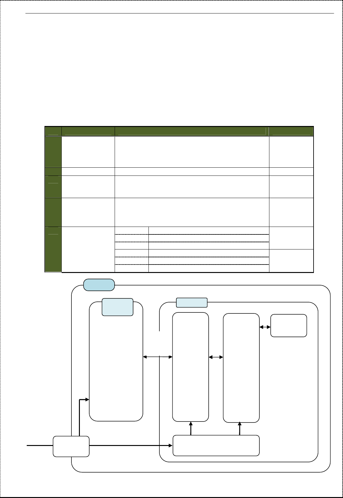
4.4 Basic specification
【
【【
【module】
】】
】
No
Item specification
1
External
interface
Wireless IEEE802. 11b
Meter Panel Connector(10pin)
Power Input : AC85~264V
2
Debug
interface
RESET FRES1/2 Short-circuit
MB86C90 JTAG:×1
AR2315 JTAG:×1
3
Display LED Status :GREEN
Alarm :AMBER
4
Security Tamper Program Deletion
5
Power Input AC-DC Conversion (120V/240V⇒3.3V)
Frequency 50/60Hz
consumption Input : Less than 8.49W(AC:120V/240V)
Output : Less than 5.94W(DC:+3.3V)
6
Condition Operating
temperature
-20℃~40℃
7
Cooling method Air cooling without blower
8
Thunder surge
Protection fuse
varistor
fuse

User manual
8/10
5. Required FCC and IC statement ( Host )
This device complies with Part 15 of the FCC Rules. Operation is subject to the following two conditions:
(1) this device may not cause harmful interference, and
(2) this device must accept any interference received, including
interference that may cause undesired operation.
5.1 FCC §15.21
Changes or modifications not expressly approved by the party responsible for compliance could void
the user’s authority to operate the equipment.
5.2 FCC §15.105
For class B equipment:
NOTE:
This equipment has been tested and found to comply with the limits for a Class B digital device, pursuant
to part 15 of the FCC Rules. These limits are designed to provide reasonable protection against harmful
interference in a residential installation. This equipment generates, uses and can radiate radio frequency
energy and, if not installed and used in accordance with the instructions, may cause harmful interference
to radio communications. However, there is no guarantee that interference will not occur in a particular
installation. If this equipment does cause harmful interference to radio or television reception, which can
be determined by turning the equipment off and on, the user is encouraged to try to correct the
interference by one or more of the following measures:
— Reorient or relocate the receiving antenna.
— Increase the separation between the equipment and receiver.
— Connect the equipment into an outlet on a circuit different from that to which the receiver is connected.
— Consult the dealer or an experienced radio/TV technician for help.
5.3 RSS-Gen §7.1.2.
Under Industry Canada regulations, this radio transmitter may only operate using an antenna of a type
and maximum (or lesser) gain approved for the transmitter by Industry Canada. To reduce potential radio
interference to other users, the antenna type and its gain should be so chosen that the equivalent
isotropically radiated power (e.i.r.p.) is not more than that necessary for successful communication.
Conformément à la réglementation d'Industrie Canada, le présent émetteur radio peut fonctionner avec
une antenne d'un type et d'un gain maximal (ou inférieur) approuvé pour l'émetteur par Industrie Canada.
Dans le but de réduire les risques de brouillage radioélectrique à l'intention des autres utilisateurs, il faut
choisir le type d'antenne et son gain de sorte que la puissance isotrope rayonnée équivalente (p.i.r.e.) ne
dépasse pas l'intensité nécessaire à l'établissement d'une communication satisfaisante.
5.4 RSS-Gen §7.1.3.
This device complies with Industry Canada licence-exempt RSS standard(s). Operation is subject to the
following two conditions:
(1) this device may not cause interference, and
(2) this device must accept any interference, including interference that may cause undesired operation
of the device.
Le présent appareil est conforme aux CNR d'Industrie Canada applicables aux appareils radio exempts
de licence. L'exploitation est autorisée aux deux conditions suivantes:
(1) l'appareil ne doit pas produire de brouillage, et
(2) l'utilisateur de l'appareil doit accepter tout brouillage radioélectrique subi, même si le brouillage est
susceptible d'en compromettre le fonctionnement.

User manual
9/10
5.5 Indicating safe separation distance warning
This equipment complies with radio frequency exposure limits set forth by the FCC and Industry
Canada for an uncontrolled environment. This equipment should be installed and operated with a
Minimum distance of 20cm between the device and the user or bystanders. This device must
Not be co-located or operating in conjunction with any other antenna or transmitter.
Cet équipement est conforme aux limites d'exposition aux radiofréquences définies par la FCC et
Industrie Canada pour un environnement non contrôlé. Cet équipement doit être installé et utilisé avec
un minimum de 20 cm de distance entre le dispositif et l'utilisateur ou des tiers. Ce dispositif ne doit pas
être utilisé a proximité d’une autre antenne ou d’un autre émetteur.
5.6 Indicating compliance with ICES-003
This Class B digital apparatus complies with Canadian ICES-003.
Cet appareil numérique de la classe or B est conforme à la norme NMB-003 du Canada

User manual
10/10
6. Required FCC and IC statement (Module)
6.1 FCC §15.21
Changes or modifications not expressly approved by the party responsible for compliance could void
the user’s authority to operate the equipment.
6.2 FCC §15.105
For class B equipment:
NOTE:
This equipment has been tested and found to comply with the limits for a Class B digital device, pursuant
to part 15 of the FCC Rules. These limits are designed to provide reasonable protection against harmful
interference in a residential installation. This equipment generates, uses and can radiate radio frequency
energy and, if not installed and used in accordance with the instructions, may cause harmful interference
to radio communications. However, there is no guarantee that interference will not occur in a particular
installation. If this equipment does cause harmful interference to radio or television reception, which can
be determined by turning the equipment off and on, the user is encouraged to try to correct the
interference by one or more of the following measures:
— Reorient or relocate the receiving antenna.
— Increase the separation between the equipment and receiver.
— Connect the equipment into an outlet on a circuit different from that to which the receiver is connected.
— Consult the dealer or an experienced radio/TV technician for help.
6.3 RSS-Gen §7.1.2.
Under Industry Canada regulations, this radio transmitter may only operate using an antenna of a type
and maximum (or lesser) gain approved for the transmitter by Industry Canada. To reduce potential radio
interference to other users, the antenna type and its gain should be so chosen that the equivalent
isotropically radiated power (e.i.r.p.) is not more than that necessary for successful communication.
Conformément à la réglementation d'Industrie Canada, le présent émetteur radio peut fonctionner avec
une antenne d'un type et d'un gain maximal (ou inférieur) approuvé pour l'émetteur par Industrie Canada.
Dans le but de réduire les risques de brouillage radioélectrique à l'intention des autres utilisateurs, il faut
choisir le type d'antenne et son gain de sorte que la puissance isotrope rayonnée équivalente (p.i.r.e.) ne
dépasse pas l'intensité nécessaire à l'établissement d'une communication satisfaisante.
6.4 RSS-Gen §7.1.3.
This device complies with Industry Canada licence-exempt RSS standard(s). Operation is subject to the
following two conditions:
(1) this device may not cause interference, and
(2) this device must accept any interference, including interference that may cause undesired operation
of the device.
Le présent appareil est conforme aux CNR d'Industrie Canada applicables aux appareils radio exempts
de licence. L'exploitation est autorisée aux deux conditions suivantes:
(1) l'appareil ne doit pas produire de brouillage, et
(2) l'utilisateur de l'appareil doit accepter tout brouillage radioélectrique subi, même si le brouillage est
susceptible d'en compromettre le fonctionnement.