Furuno USA 9ZWFA170 Automatic Identification Systems User Manual IME 44900 A
Furuno USA Inc Automatic Identification Systems IME 44900 A
UserManual.wiki
>
Furuno USA
>
9ZWFA170 User Manual
>
Installation Manual
Contents
1.
Installation Manual
2.
Installation Manual II
3.
User Manual
4.
User Manual II
Installation Manual
Navigation menu
Upload a User Manual
Namespaces
Wiki Guide
HTML
PDF
Info
Views
User Manual
Discussion / Help
Navigation
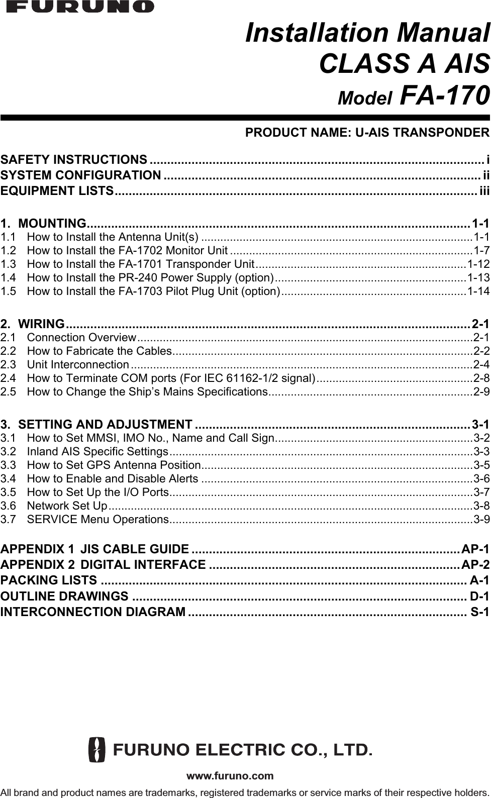
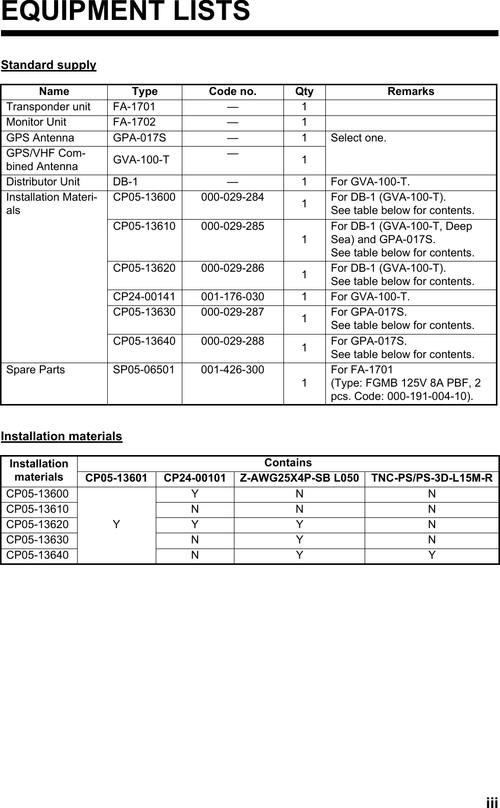
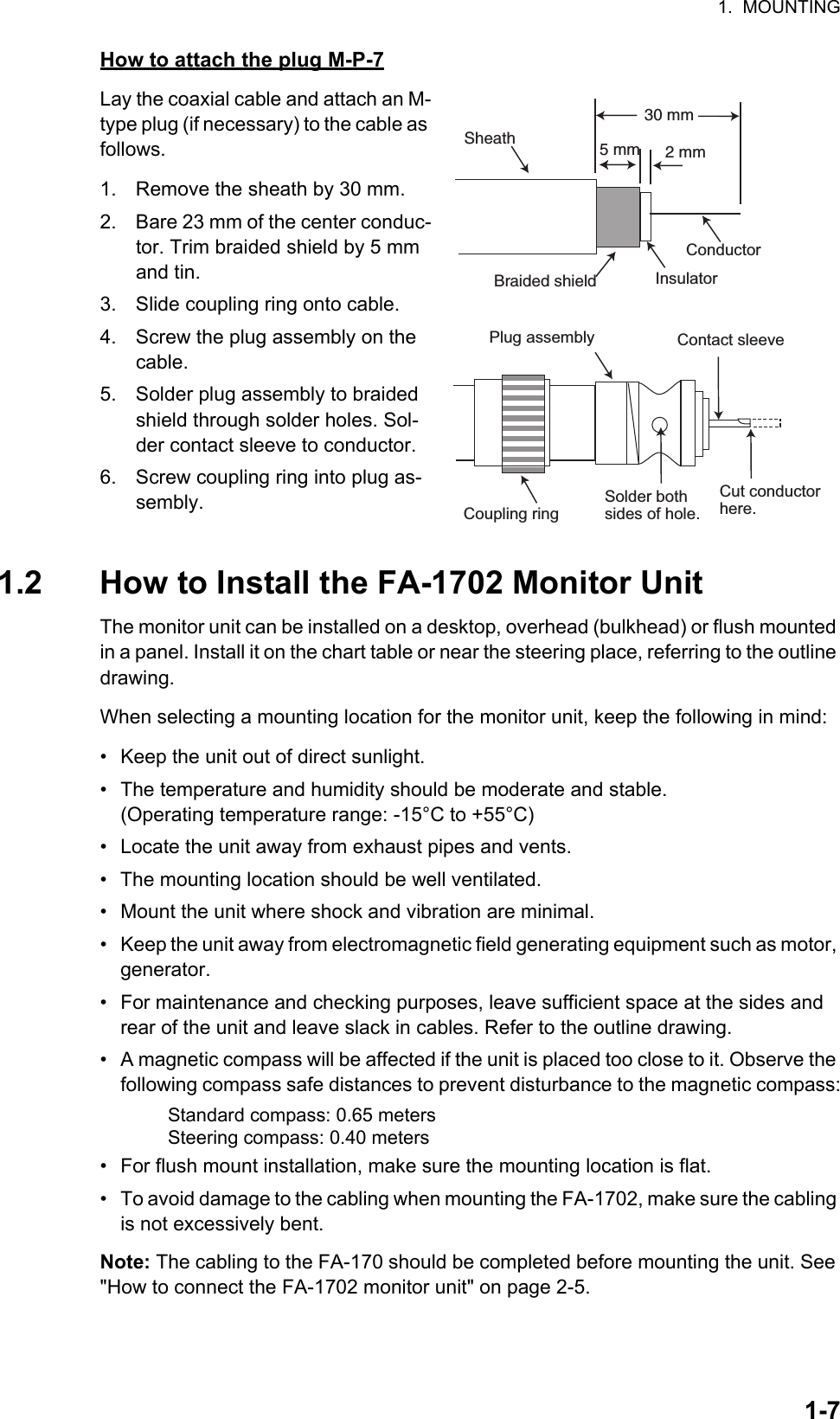

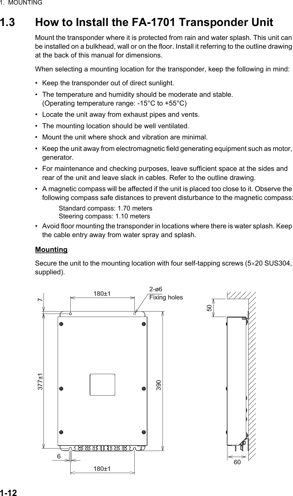
![2. WIRING2-22.2 How to Fabricate the CablesLAN cable fabrication 1 WHT/GRN2 GRN3 WHT/ORG4 BLU5 WHT/BLE6 ORG7 WHT/BRN8 BRNWHT/ORG 1ORG 2WHT/GRN 3BLU 4WHT/BLE 5GRN 6WHT/BRN 7BRN 81 WHT/ORG2 ORG3 WHT/GRN4 BLU5 WHT/BLE6 GRN7 WHT/BRN8 BRNWHT/ORG 1ORG 2WHT/GRN 3BLU 4WHT/BLE 5GRN 6WHT/BRN 7BRN 8Expose inner vinyl sheath.[Cross-over cable] [Straight cable]Remove the outer sheath by approx 25 mm. Be careful not to damage inner shield and cores.Fold back the shield, wrap it onto the outer sheath and cut it, leaving 9 mm.12325 mmapprox. 9 mm456approx. 9 mm approx. 11 mmDrain wireFold back drain wire and cut it, leaving 9 mm.Straighten and flatten the cores in order then cut them, leaving 11 mm.Insert the cable into the modular plug so that the folded part of the shield enters the modular plug. The drain wire must be on the tab side of the jack.18Modular plugCable jacketOuter sheath Inner sheathCover the cable jacket with insulated tape (20 mm width)Approx. 200 mm80ShieldingExpose the inner and outer sheaths as shown to the left.Cover the cable jacket at the cut as shown to the left.Using special crimping tool MPT5-8AS (PANDUIT CORP.), crimp the modular plug. Finally check the plug visually.7](https://usermanual.wiki/Furuno-USA/9ZWFA170.Installation-Manual/User-Guide-2884865-Page-22.png)

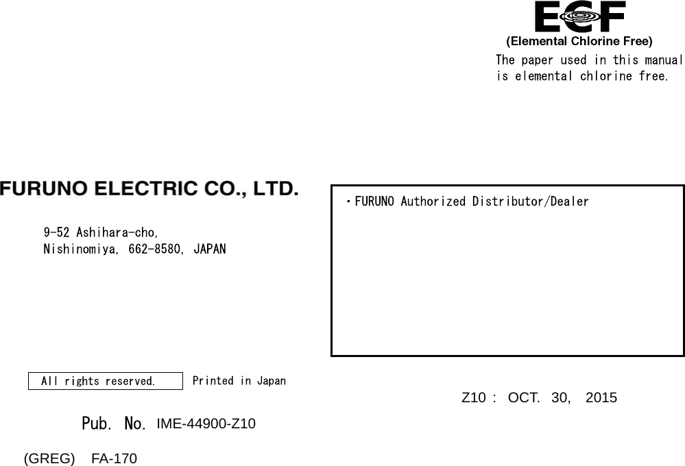
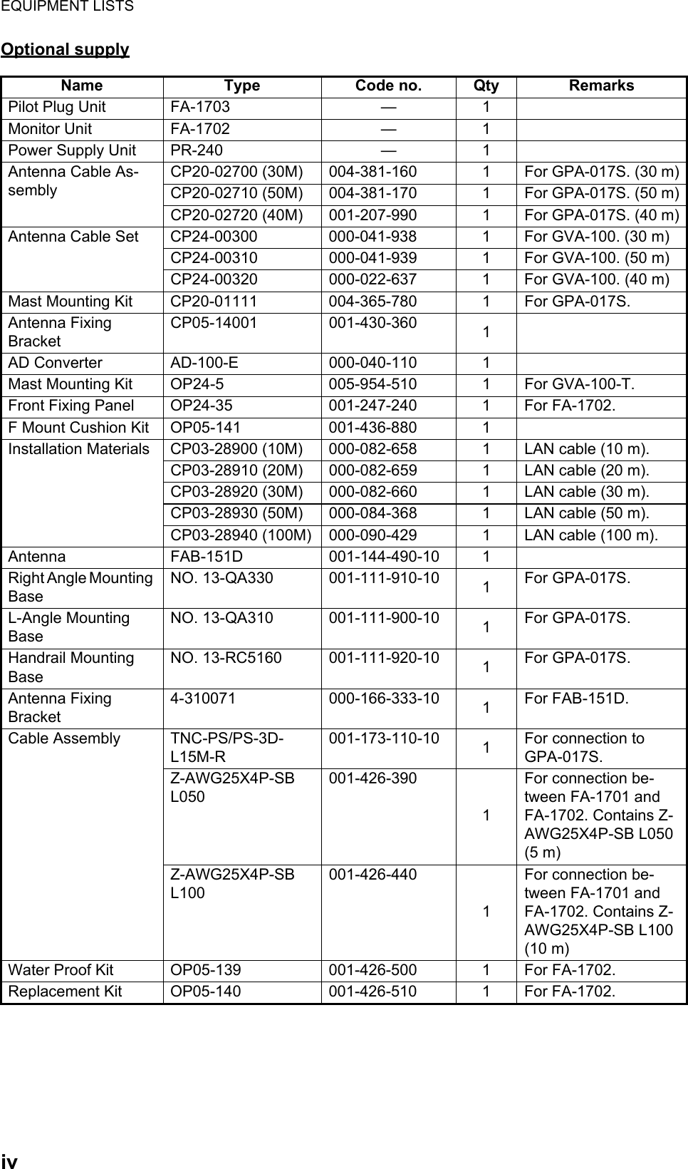
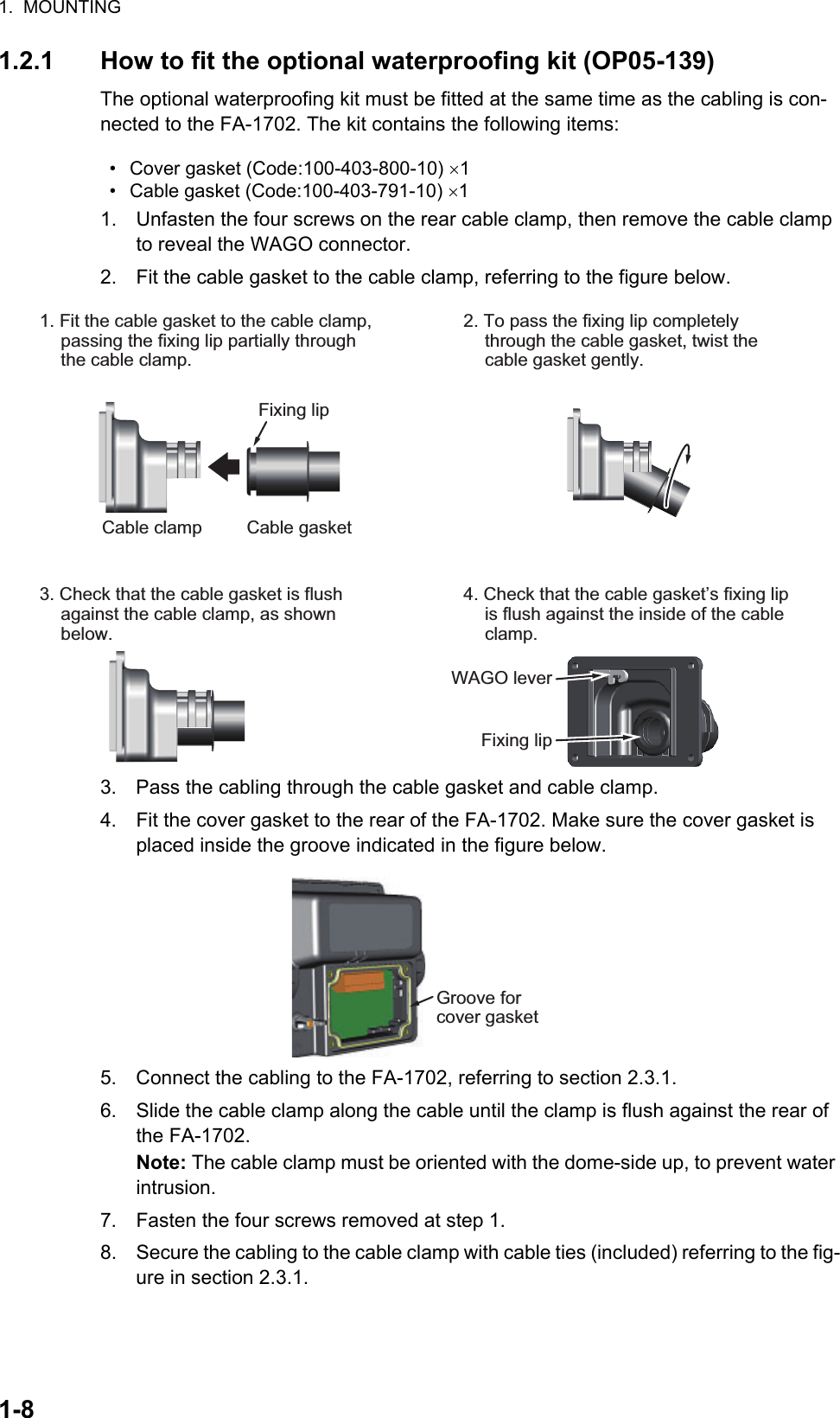
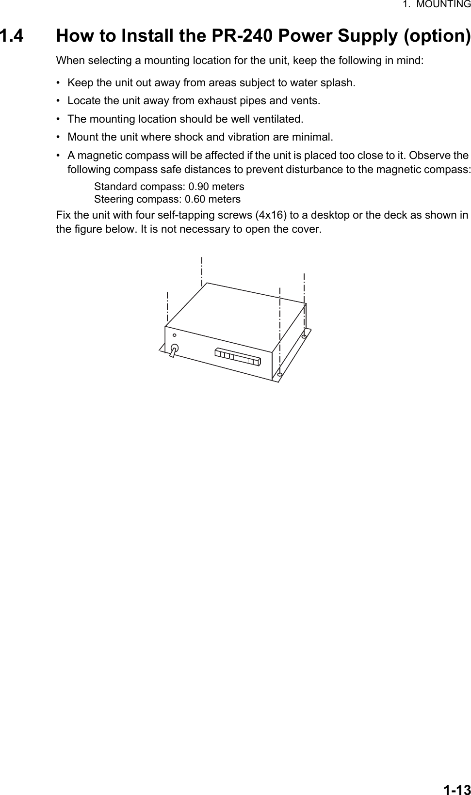
![3-13. SETTING AND ADJUSTMENTAfter installing the equipment, set up the own ship’s static information (MMSI, IMO number, ship’s name, call sign, type of ship and GPS antenna position). Also, set up the I/O ports.How to access the [INITIAL SET] menuThe [INITAL SET] menu can be accessed at any time, however settings are password locked and require a qualified technician or dealer for password input.1. Press the MENU/ESC key to open the menu.2. Select [INITIAL SET], then press the ENT/ACK key.3. Select [EDIT], then press the ENT/ACK key. A pop up options window is dis-played.4. Select [UNLOCK], then press the ENT/ACK key. The password entry screen is displayed.5. Input the password, then press the ENT/ACK key.If the password is correct. the indication for [EDIT] reads "UNLOCK" and the [INITIAL SET] menu items can be edited. The lock icon, found on all settings screens also changes to a blue colored open lock icon.MSGSTATUSUSER SETINITIAL SETCH INFODIAGNOSTICSSERVICEMENU123456LOCKUNLOCKINITIAL SETSHIP’S INFORMATIONANTENNA POSITIONALERT ENABLEI / O PORTPORT PRIORITYNETWORKEDIT : LOCK1234567PASSWORD FOR INITIAL SET: BACKMENU](https://usermanual.wiki/Furuno-USA/9ZWFA170.Installation-Manual/User-Guide-2884865-Page-31.png)
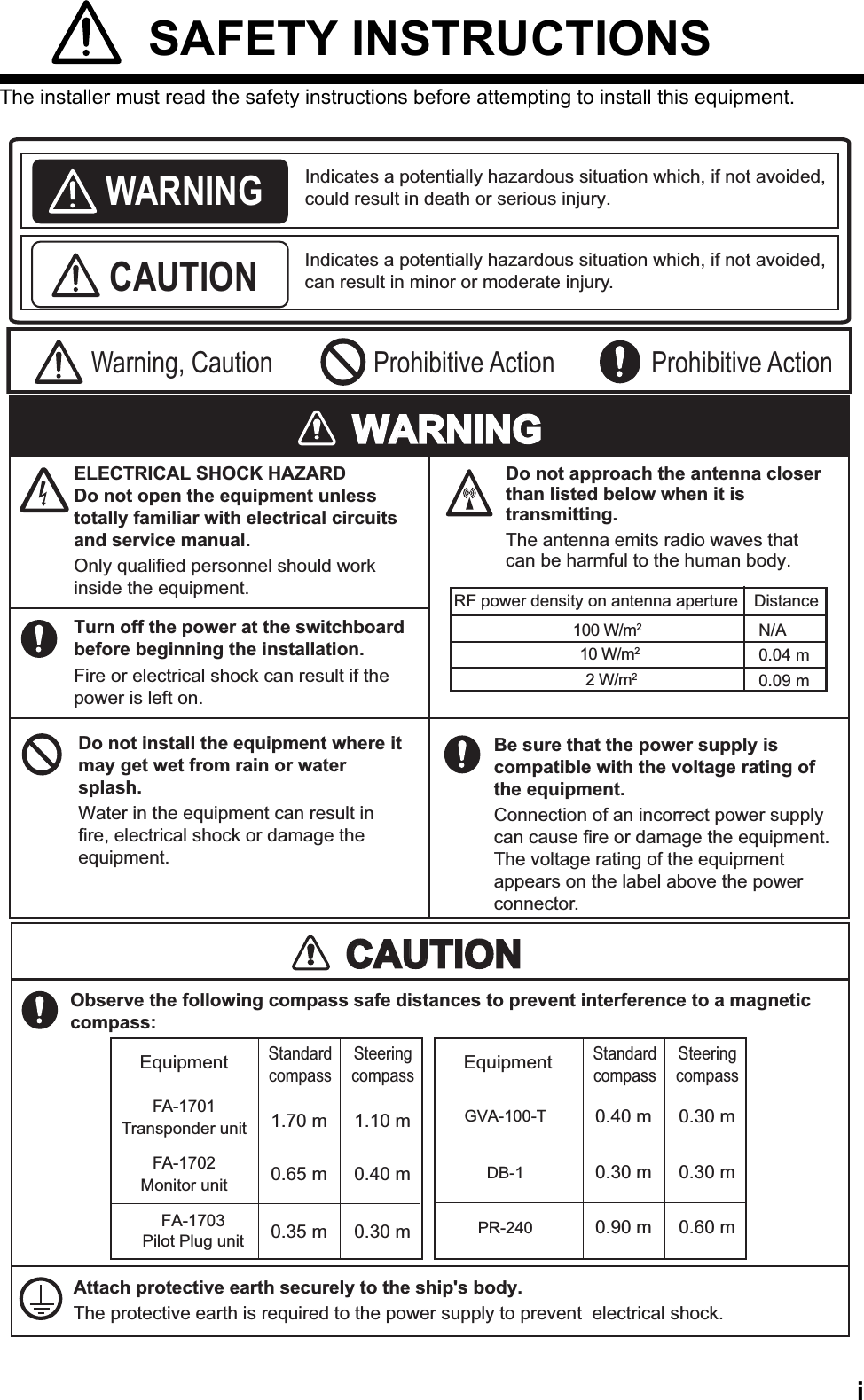
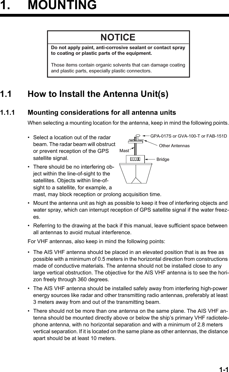
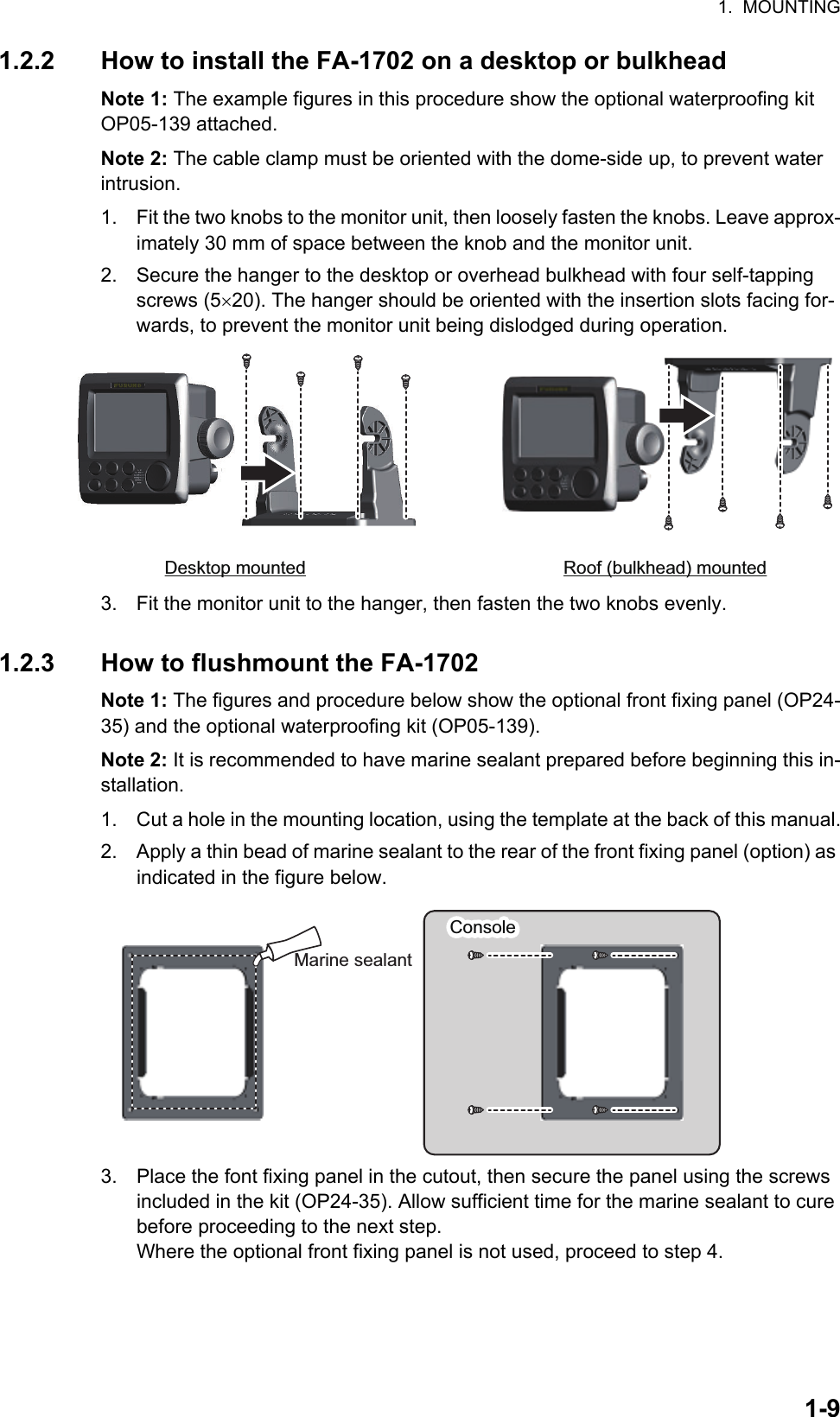
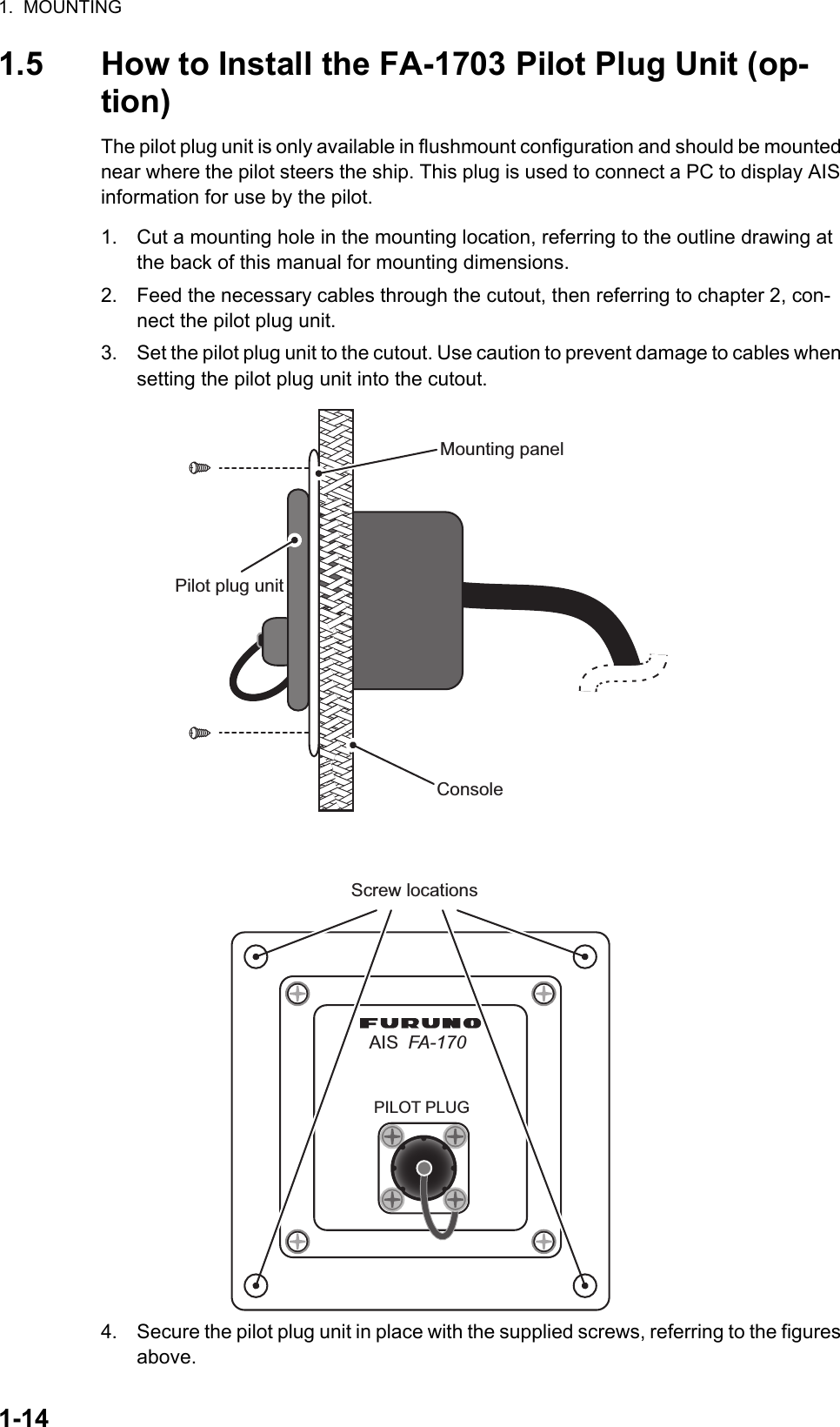
![3. SETTING AND ADJUSTMENT3-23.1 How to Set MMSI, IMO No., Name and Call Sign1. Access the [INITIAL SET] menu, following the procedure outlined in "How to ac-cess the [INITIAL SET] menu" on page 3-1.2. Select [SHIP’S INFORMATION], then press the ENT/ACK key.3. Select [MMSI], then press the ENT/ACK key to display the [MMSI] pop up win-dow.Note: [ENI], [SPEED QUALITY], [COURSE QUALITY], [HEADING QUALITY] and [BLUE SIGN SW] are Inland AIS settings. These items do not appear for other AIS modes.4. Use the arrow keys to set the [MMSI], then press the ENT/ACK key. The selected digit cycles through characters in the following order when is pressed: 1, 2 ... 9, 0, 1, 2... press to cycle through characters in the opposite direction. Press or to move the selection cursor.5. Input the IMO number in a similar manner to MMSI. IMO: Ten digits. If the IMO number has 8 digits, enter “0” twice followed by IMO number. If the ship has no IMO number, enter ten zeros.6. For [NAME] and [CALL SIGN], the software keyboard is displayed when the item is selected.1) Referring to the figure above, press the arrow keys to select a character or keyboard operation.2) Press the ENT/ACK key to confirm your selection.3) Repeat steps 1 and 2 to complete the alphanumeric input.4) Select [SET], then press the ENT/ACK key.7. Select [TYPE OF SHIP] referring to section 1.5 of the operator’s manual, then press the ENT/ACK key.8. After entering data, press the DISP key to close the menu.Note: If you enter incorrect data, do the procedure from step 1.SHIP’S INFORMATIONMMSI 234556789FURUNOMARU1234567890SPEED QUALITY HIGHHIGHHIGHUNUSECOURSE QUALITYHEADING QUALITYBLUE SIGN SW(WIG)24@SEVEN@00100000NAMEIMO NO.CALL SIGNENITYPE OF SHIP00750076[LONG RANGE]CH ACH B: BACKMENU000000000MMSINot shown where [REGULATION] is set to [JAPAN].TEXTCursor position is shown as a blue bar. Backspace - Erase the character to the left of the cursor.Delete - Erase the character to the right of the cursor.Cursor locators - Press ► to move the cursor right, ◄ to move the cursor left.SET - Apply the changes.Current selection is highlighted in blue.Keyboard operation keys](https://usermanual.wiki/Furuno-USA/9ZWFA170.Installation-Manual/User-Guide-2884865-Page-32.png)
![3. SETTING AND ADJUSTMENT3-33.2 Inland AIS Specific SettingsThis section shows how to activate and set up the Inland AIS feature. (If this feature is not required, go to "How to Set MMSI, IMO No., Name and Call Sign" on page 3-2.) The AIS activation key is obtained from the place of purchase.3.2.1 How to Activate the Inland AISInput your key number (received from dealer) to activate the Inland AIS.1. Press the MENU/ESC key to open the menu.2. Select [USER SET] then press the ENT/ACK key.3. Select [ACTIVATE] then press the ENT/ACK key.4. Press the ENT/ACK key to display the alphanumeric pop up window.The selected digit cycles through characters in the following order when is pressed: 1, 2 ... 8, 9, A, B, C ... X, Y, Z, 1, 2... press to cycle through characters in the opposite direction. Press or to move the selection cursor.5. Input the activation key, then press the ENT/ACK key.If you entered the activation key correctly, the indication "ACTIVATED. SYSTEM WILL RESTART" appears then the system is automatically restarted.MSGSTATUSUSER SETINITIAL SETCH INFODIAGNOSTICSSERVICEMENU123456AUTOONHIDEAUTO SORTSART TESTLR RESPONSE234::::USER SETON+00 : 00ONKEY BEEPTIME DIFFLR BROADCASTNOTIFICATION SET156ACTIVATE78::ACTIVATEDEVICE ID AB-12-C3-ZD-AA-N4_ _-_ _-_ _-_ _-_ _-_ _ACITVATE KEY INACTIVATED: SELECTENT: BACKMENU:0ACTIVATE KEY](https://usermanual.wiki/Furuno-USA/9ZWFA170.Installation-Manual/User-Guide-2884865-Page-33.png)
![3. SETTING AND ADJUSTMENT3-43.2.2 How to set blue sign statusBlue sign (a day-sign), which in combination with a white flashing light, must be shown if you are sailing on the port-side shore (against traffic direction).1. Access the INITIAL SET menu, following the procedure outlined in "How to access the [INITIAL SET] menu" on page 3-1.2. Select [SHIP’S INFORMATION] then press the ENT/ACK key. 3. Select [BLUE SIGN SW], then press the ENT/ACK key. A pop up options window is displayed.4. Select [UNUSE] (not in use) or [USE] (in use) as applicable, then press the ENT/ACK key. 3.2.3 Other inland AIS specific settingsInland AIS requires the following additional settings:ENI:1. Select [ENI], then press the ENT/ACK key to display the [ENI] pop up window.2. Use the arrow keys to set the [ENI], then press the ENT/ACK key. The selected digit cycles through characters in the following order when is pressed: 1, 2 ... 9, 0, 1, 2... press to cycle through characters in the opposite direction. Press or to move the selection cursor.Sensor qualitySet [SPEED QUALITY], [COURSE QUALITY] and [HEADING QUALITY] as follows:1. Select [SPEED QUALITY], then press the ENT/ACK key to display the [SENSOR QUALITY (SPEED)] pop up window.2. Select the [HIGH] or [LOW] as appropriate, then press the ENT/ACK key.Select [HIGH] where there is more are multiple referenced sensors, giving a high-er quality reading.Select [LOW] where there is only one or two sensors, giving a reading which may require periodic adjustment.3. Set [COURSE QUALITY] and [HEADING QUALITY] in the same manner.SHIP’S INFORMATIONMMSI 234556789FURUNOMARU1234567890SPEED QUALITY HIGHHIGHHIGHUNUSECOURSE QUALITYHEADING QUALITYBLUE SIGN SW(WIG)24@SEVEN@00100000NAMEIMO NO.CALL SIGNENITYPE OF SHIP00750076[LONG RANGE]CH ACH B: BACKMENUBLUE SIGN SWUSEUNUSE: SELECTENT: CURSOR](https://usermanual.wiki/Furuno-USA/9ZWFA170.Installation-Manual/User-Guide-2884865-Page-34.png)
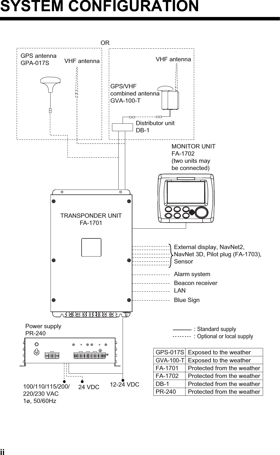
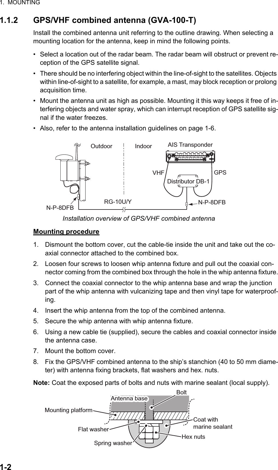
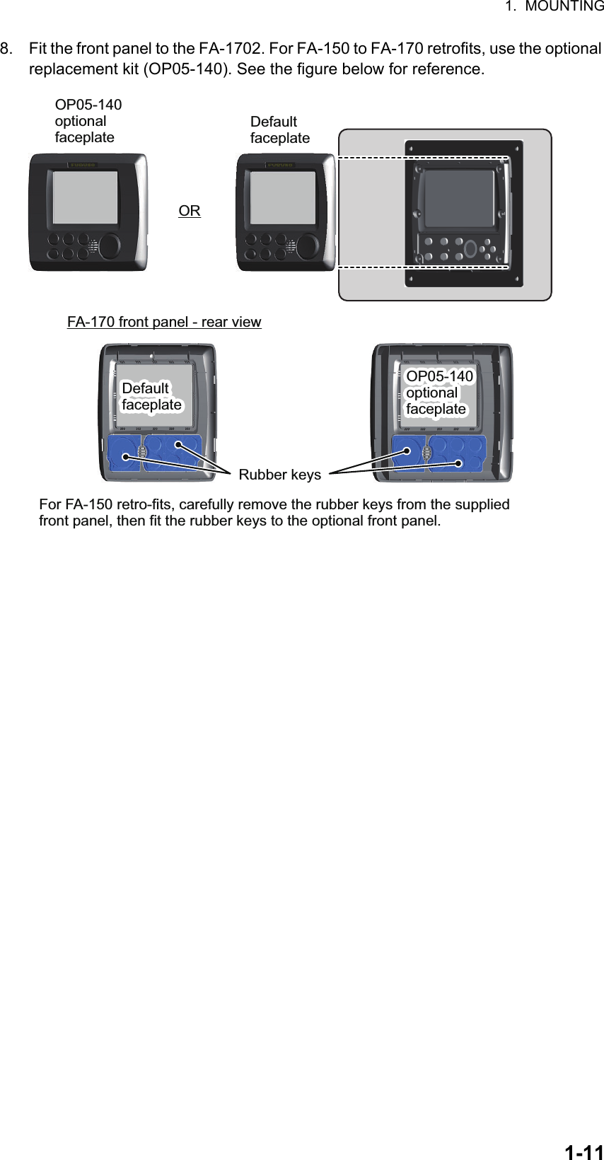
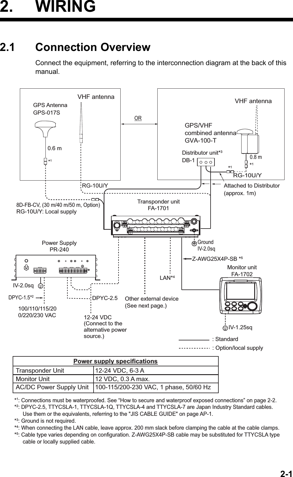
![3. SETTING AND ADJUSTMENT3-53.3 How to Set GPS Antenna Position1. Access the [INITIAL SET] menu, following the procedure outlined in "How to ac-cess the [INITIAL SET] menu" on page 3-1.2. Select [ANTENNA POSITION], then press the ENT/ACK key. The settings screen for [ANTENNA POSITION] is displayed.3. The [LENGTH] option is selected, press the ENT/ACK key to input the vessel length. The available range for length is 0 m to 800 m. Press the ENT/ACK key to apply the setting.4. Select [BEAM], then press the ENT/ACK key to input the vessel beam. The avail-able range for beam is 0 m to 100 m. Press the ENT/ACK key to apply the setting.5. Select the Y indication for the internal antenna, then press the ENT/ACK key. A settings pop up window is displayed. The pop up shows the available setting range at the bottom.The Y axis coordinates are calculated from the stern of your vessel. The setting range varies depending on your vessel’s dimensions.6. Set the bow-stern location for the antenna, then press the ENT/ACK key.7. Select the X indication for internal antenna, then press the ENT/ACK key.The X coordinates are calculated from the center of the vessel. Negative settings give a port-side positioning, positive settings give a starboard-side positioning.8. Set the port-starboard location for the antenna, then press the ENT/ACK key.9. Set the location for the external antenna, then press the ENT/ACK key. A settings pop up window is displayed. The pop up shows the available setting range at the bottom.Note: The settings for the antenna location are reflected at the bottom of the screen, in gray, as [A,B] for bow-stern positioning and [C,D] for port-starboard po-sitioning, and the antenna numbers are also shown in the right-hand mini-window.10. Press the MENU/ESC key to return to the [INITIAL SET] menu.ANTENNA POSITION[SHIP SIZE][ANT POSN][ANT POSN]LENGTHINTERNALEXTERNALINTERNALEXTERNALYYXXBEAM: SELECT0m 0m0m0m0m0m00,0000,00 00,0000,00A,B C,DENT: BACKMENU1212: CURSORX axis Y axis Antenna position XCABDYBEAM(0 m to 100 m)LENGTH(0 m to 800 m)(0 m to 800 m)YX: BACKMENU12Antenna locations are reflected in the right-hand mini-window.](https://usermanual.wiki/Furuno-USA/9ZWFA170.Installation-Manual/User-Guide-2884865-Page-35.png)