Furuno USA 9ZWFA170 Automatic Identification Systems User Manual IME 44900 A

Furuno USA Inc Automatic Identification Systems IME 44900 A

Contents

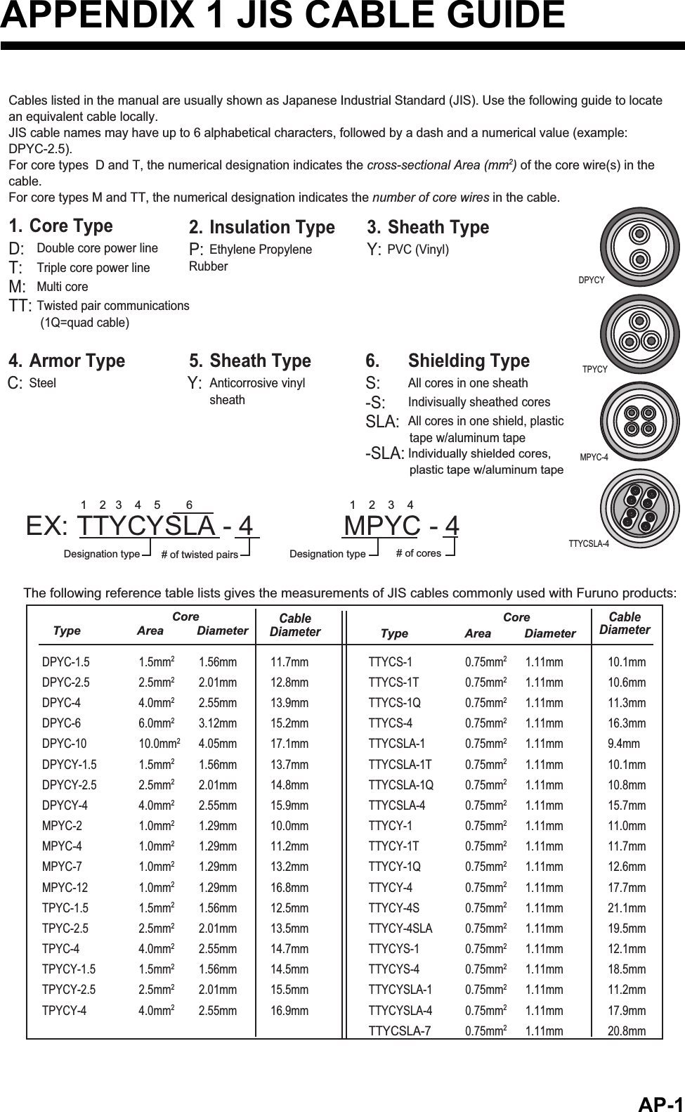
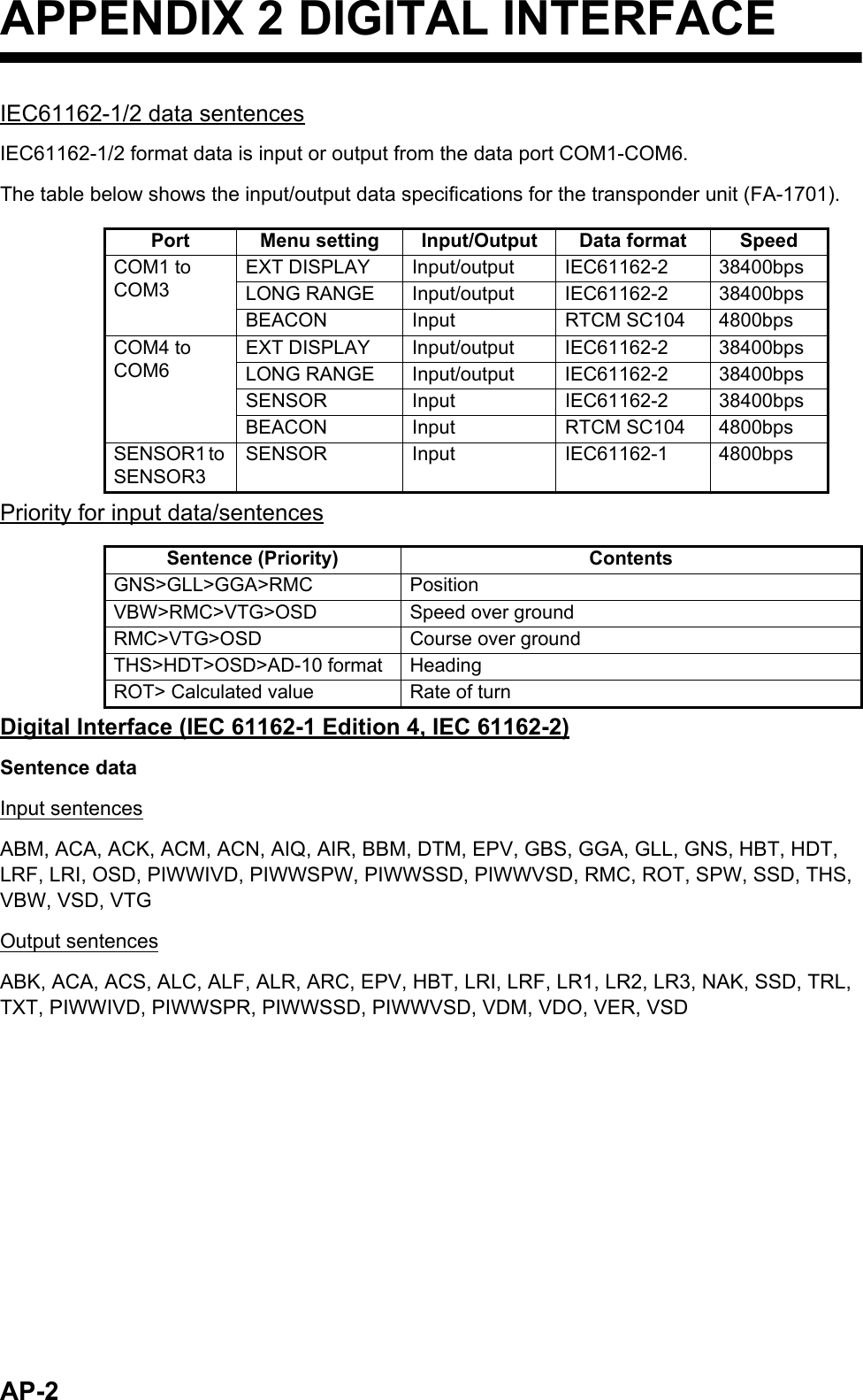
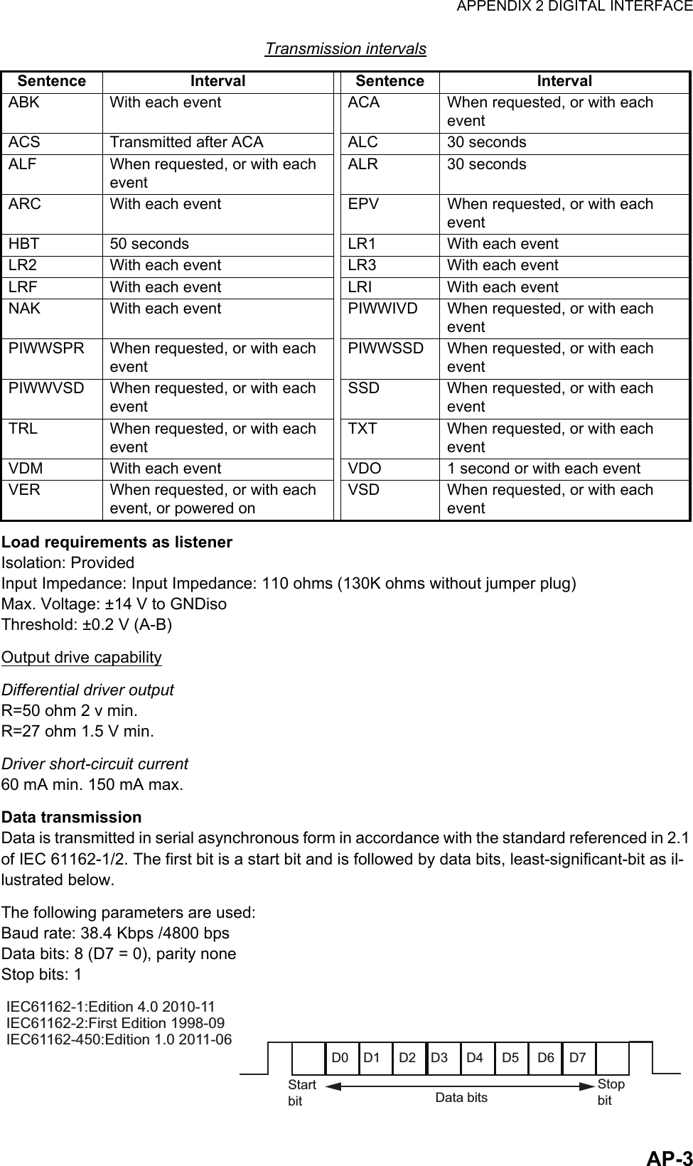
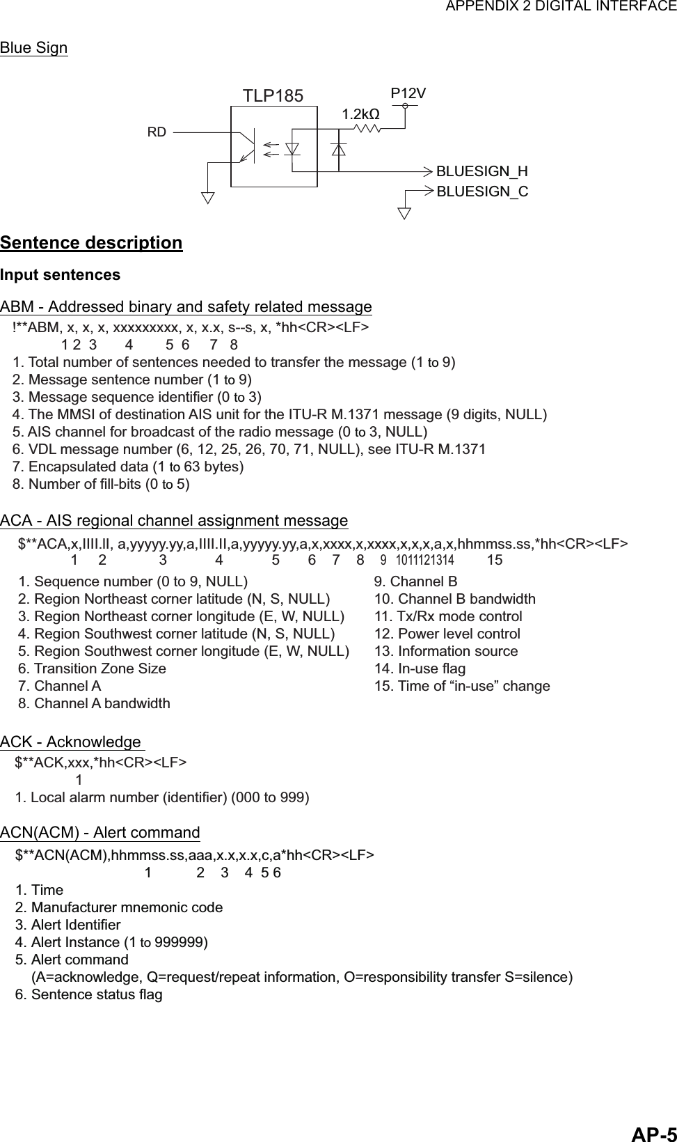
Installation Manual II

3.  SETTING AND ADJUSTMENT3-63.4 How to Enable and Disable AlertsYou can enable or disable alerts from the [ALERT ENABLE] menu. Disabling an alert in this menu will disable all related alerts for the disabled alert. Note: All alerts are set to [ENABLE] by default.1. Access the [INITIAL SET] menu, following the procedure outlined in "How to ac-cess the [INITIAL SET] menu" on page 3-1.2. Select [ALERT ENABLE], then press the ENT/ACK key.Active/unacknowledged alerts are displayed with an alert icon next to the alert ID.3. Select an alert, then press the ENT/ACK key to enable or disable the alert. Enabled alerts are displayed in green color text, disabled alerts are displayed in gray color text.4. Press the MENU/ESC key to return to the [INITIAL SET] menu.ALERT ENABLE: BACK: CURSORMENU: ENABLE/DISABLEENTWARNING1 WARNING2ENABLE001 014026030029005007009010008011025035032002003004DISABLEENABLEHILO001 :TX MALFUNCTIONDISABLE: 8 : 0 : 0: 9Cursor selection is highlightedSelected alert’s detailsDisabled alerts are displayed in gray.
3.  SETTING AND ADJUSTMENT3-73.5 How to Set Up the I/O Ports1. Access the [INITIAL SET] menu, following the procedure outlined in "How to ac-cess the [INITIAL SET] menu" on page 3-1.2. Select [I/O PORT], then press the ENT/ACK key.Note: The figure above shows the default settings for all ports.The available port settings are outlined in the table on the following page.Note 1: When [MODE] is set to [BEACON] or [MONITOR], speed settings are fixed at the default setting.Note 2: For detailed information on data format and related speeds, see "DIGITAL INTERFACE" on page AP-2.Mode definitionsPORT MODE SPEED (baud)COM1 EXT DISPLAY 4800, 38400LONG RANGE 4800, 38400BEACON 4800MONITOR 57600SERVICE 4800, 38400DISABLE -COM2 to COM3 Same as COM1. Same as COM1.COM4 EXT DISPLAY 4800, 38400LONG RANGE 4800, 38400SENSOR 4800, 38400BEACON 4800MONITOR 57600SERVICE 4800, 38400DISABLE -COM5 to COM6 Same as COM4. Same as COM4.SENSOR1 SENSOR Fixed at 4800DISABLE -SENSOR2 & SENSOR3 Same as SENSOR1. Same as SENSOR1.MODE DefinitionEXT DISPLAY External display (Radar, ECDIS, Pilot plug, etc.)LONG RANGE Long range communication device (Inmarsat C, etc.)SENSOR GPS, Gyrocompass, ROT, etc.MONITOR For FA-1702 Monitor Unit.BEACON For Beacon Receiver.SERVICE For service personnel only. Do not use.DISABLE Disable the port.EXT DISPLAYEXT DISPLAYEXT DISPLAYI / O PORTPORTCOM1MODE SPEED38400baudCOM2 EXT DISPLAYEXT DISPLAY38400baudCOM3 EXT DISPLAY 38400baudCOM4SENSORSENSORSENSOR38400baudCOM5 38400baudCOM6 38400baudSENSOR1 4800baudSENSOR2 4800baudSENSOR3 4800baud: SELECT: CURSORENT: BACKENT
3.  SETTING AND ADJUSTMENT3-83.5.1 How to set port priority1. Access the [INITIAL SET] menu, following the procedure outlined in "How to ac-cess the [INITIAL SET] menu" on page 3-1.2. Select [PORT PRIORITY], then press the ENT/ACK key.3. Select the sensor whose priority you want to adjust, then press the ENT/ACK key. The [SENSOR PORT] pop up window is displayed.4. Select the appropriate port, then press the ENT/ACK key.5. Repeat step 3 to step 4 for other port priorities.6. Press the MENU/ESC key to return to the [INITAL SET] menu.3.6 Network Set Up1. Access the [INITIAL SET] menu, following the procedure outlined in "How to ac-cess the [INITIAL SET] menu" on page 3-1.2. Select [NETWORK], then press the ENT/ACK key.3. [IP ADDRESS] is selected. Press the ENT/ACK key to set the IP address for the FA-170 within the network.4. Select and set [SUBNET MASK] and [GATEWAY] in a similar fashion. For NAVNET networks, go to step 5, for other network types, go to step 12.5. Select [NAVNET PORT], then press the ENT/ACK key.6. Input the NAVNET port which this unit is connected to, then press the ENT/ACK key.7. Select [HOST NAME], then press the ENT/ACK key.8. Input the name for this unit within the NAVNET network.9. Select [AIS INFO], then press the ENT/ACK key.PORT PRIORITYPRIORITY1stLL/COG/COGSENSOR1HDG ROT2nd SENSOR23rd SENSOR34th COM4COM5COM6SENSOR3SENSOR1SENSOR2COM6COM4COM5SENSOR3SENSOR1SENSOR2COM6COM4COM55th6th: SELECT: CURSORENT: BACKENTSelected item is highlighted in reverse video.SENSOR PORTSENSOR1SENSOR2SENSOR3COM4COM5COM6NETWORK: CURSOR: SELECT172 . 031 . 024 . 004255 . 255 . 000 . 000000 . 000 . 000 . 000AI0001ENT: BACKMENUIP ADDRESSSUBNET MASKGATEWAYSFI<SAVE>NETWORK  (NAVNET): CURSOR: SELECT172 . 031 . 024 . 004255 . 255 . 000 . 000000 . 000 . 000 . 00010000ENT: BACKMENUIP ADDRESSSUBNET MASKGATEWAYNAVNET PORTAIS0HOST NAMEONAIS INFOOFFZDA INFOOFFGPS INFO[OUTPUT AT STARTUP]<SAVE>Standard network settings screen. NAVNET network settings screen.
3.  SETTING AND ADJUSTMENT3-910. Select [ON] to enable AIS data output to the NAVNET network when this unit is turned on. Select [OFF] to disable AIS data output when this unit is turned on.11. Set [ZDA INFO] and [GPS INFO] in the same manner as [AIS INFO], then go to step 14.12. Select [SFI], then press the ENT/ACK key.13. Set the [SFI] (System Function ID), then press the ENT/ACK key.14. Confirm the settings are correct, then select [<SAVE>] and press the ENT/ACK key. A confirmation pop up is displayed.Note: If no changes are made to the settings, [<SAVE>] is not selectable.15. Select [NO] to change the settings further. Select [YES] to accept the new set-tings, the unit now shuts down automatically to apply the new settings. When the unit is shut down, press the power key to restart the unit.3.7 SERVICE Menu OperationsThe [SERVICE] menu is password protected. Contact FURUNO for password details.The following items require access to the SERVICE for initial setup:•  ALERT MODE settings• Network protocol settings•  Restore Factory settings3.7.1 How to access the SERVICE menu1. From the [MAIN] menu, select [SERVICE], then press the ENT/ACK key. The password input pop up appears.2.  Input the password then press the ENT/ACK key.3.7.2 How to set the alert modeThe alert mode can be set according to the vessel’s configuration. The available alert modes are: [LEGACY ED.1], [LEGACY ED.2], [ALERT IF1] and [ALERT IF2].1. Access the [SERVICE] menu referring to the procedure outlined at the start of this section.2. Select [ALERT SET], then press the ENT/ACK key.3. Select [ALERT MODE], then press the ENT/ACK key.Note: The [OPERATIONAL] setting is for technical personnel only. Do not change this setting.4. Select the appropriate [ALERT MODE] setting, then press the ENT/ACK key.Select [ALERT IF1] for vessels configured with AMS, [ALERT IF2] for vessels con-figured with BAM.5. Press the MENU/ESC key to return to the [INTIAL SET] menu, or press the DISP key to close all open menus.SERVICECH SETAIS SETALERT SETFACTORY SETOTHER SETINITIALIZE123456TEST7MAINTENANCE8DEVELOPER9ALERT SETALERT MODE LEGACY ED.2OPERATIONAL12LEGACY ED.1LEGACY ED.2ALERT IF1ALERT IF2
3.  SETTING AND ADJUSTMENT3-103.7.3 How to set the network protocolSet the LAN network protocol according to your vessel’s on-board network. [NAVNET] protocol should be used where a NavNet series unit is the LAN network hub. Select [450] for all other LAN networks.1. Access the [SERVICE] menu referring to the procedure outlined at the start of this section.2. Select [OTHER SET], then press the ENT/ACK key.3. Select [NW PROTOCOL], then press the ENT/ACK key.Note: The rest of the [OTHER SET] menu items are for technical personnel only. Do not change these setting.4. Select the appropriate protocol, then press the ENT/ACK key. A confirmation pop up is displayed.5. Select [YES] to accept the new setting, [NO] to cancel and return to the options. Selecting [YES] will restart the unit.3.7.4 How to restore factory settingsThis procedure resets the units to factory settings.Be sure to set all appropriate settings from the [INITIAL SET] menu after completing this procedure.1. Access the [SERVICE] menu referring to the procedure outlined at the start of this section.2. Select [INTIALIZE], then press the ENT/ACK key.3. Select [RESTORE FACTORY SET], then press the ENT/ACK key. The confirma-tion pop up window shown below-right is displayed.Note: The rest of the [INTIALIZE] menu items are for technical personnel only. Do not change these settings.4. Select the [YES] or [NO] as appropriate, then press the ENT/ACK key.[YES]: Accept the new settings and restart the unit.[NO]: Cancel and return to the options.OTHER SETNW PROTOCOL 450CHECKSUM12450NAVNETALL  CPASSWINITIALIZERESTORE FACTORY SET123NOINITIALIZE SETTINGS OK?YES
AP-1APPENDIX 1 JIS CABLE GUIDECoreType                 Area          DiameterThe following reference table lists gives the measurements of JIS cables commonly used with Furuno products:TTYCSLA-4MPYC-4TPYCY DPYCY Cable DiameterDPYC-1.5 1.5mm2 1.56mm  11.7mmDPYC-2.5 2.5mm2 2.01mm  12.8mmDPYC-4 4.0mm2 2.55mm  13.9mmDPYC-6 6.0mm2 3.12mm 15.2mmDPYC-10 10.0mm2 4.05mm  17.1mmDPYCY-1.5 1.5mm2 1.56mm 13.7mmDPYCY-2.5 2.5mm2 2.01mm  14.8mmDPYCY-4 4.0mm2 2.55mm  15.9mmMPYC-2 1.0mm2 1.29mm  10.0mmMPYC-4 1.0mm2 1.29mm  11.2mmMPYC-7 1.0mm2 1.29mm  13.2mmMPYC-12 1.0mm2 1.29mm  16.8mmTPYC-1.5 1.5mm2 1.56mm  12.5mmTPYC-2.5 2.5mm2 2.01mm  13.5mmTPYC-4 4.0mm2 2.55mm  14.7mmTPYCY-1.5 1.5mm2 1.56mm  14.5mmTPYCY-2.5 2.5mm2 2.01mm  15.5mmTPYCY-4 4.0mm2 2.55mm  16.9mmTTYCS-1 0.75mm2 1.11mm  10.1mmTTYCS-1T 0.75mm2 1.11mm  10.6mmTTYCS-1Q 0.75mm2 1.11mm  11.3mmTTYCS-4 0.75mm2 1.11mm  16.3mmTTYCSLA-1 0.75mm2 1.11mm  9.4mmTTYCSLA-1T 0.75mm2 1.11mm  10.1mmTTYCSLA-1Q 0.75mm2 1.11mm  10.8mmTTYCSLA-4 0.75mm2 1.11mm  15.7mmTTYCY-1 0.75mm2 1.11mm  11.0mmTTYCY-1T 0.75mm2 1.11mm  11.7mmTTYCY-1Q 0.75mm2 1.11mm  12.6mmTTYCY-4 0.75mm2 1.11mm  17.7mmTTYCY-4S 0.75mm2 1.11mm  21.1mmTTYCY-4SLA 0.75mm2 1.11mm  19.5mmTTYCYS-1 0.75mm2 1.11mm  12.1mmTTYCYS-4 0.75mm2 1.11mm  18.5mmTTYCYSLA-1 0.75mm2 1.11mm  11.2mmTTYCYSLA-4 0.75mm2 1.11mm  17.9mmTTYCSLA-7 0.75mm2 1.11mm  20.8mmEX: TTYCYSLA - 4            MPYC - 4Designation type # of twisted pairs Designation type # of cores1    2   3    4    5        6                                                 1    2    3    4Cables listed in the manual are usually shown as Japanese Industrial Standard (JIS). Use the following guide to locate an equivalent cable locally.JIS cable names may have up to 6 alphabetical characters, followed by a dash and a numerical value (example: DPYC-2.5).For core types  D and T, the numerical designation indicates the cross-sectional Area (mm2) of the core wire(s) in the cable.For core types M and TT, the numerical designation indicates the number of core wires in the cable.1. Core TypeD:  Double core power lineT:  Triple core power lineM:  Multi coreTT: Twisted pair communications (1Q=quad cable)2. Insulation TypeP: Ethylene Propylene Rubber3. Sheath TypeY: PVC (Vinyl)4. Armor TypeC: Steel5. Sheath TypeY:  Anticorrosive vinyl sheath6. Shielding TypeS:  All cores in one sheath-S:  Indivisually sheathed coresSLA:  All cores in one shield, plastic tape w/aluminum tape-SLA: Individually shielded cores, plastic tape w/aluminum tapeCoreType                 Area          DiameterCable Diameter
AP-2APPENDIX 2 DIGITAL INTERFACEIEC61162-1/2 data sentencesIEC61162-1/2 format data is input or output from the data port COM1-COM6.The table below shows the input/output data specifications for the transponder unit (FA-1701).Priority for input data/sentencesDigital Interface (IEC 61162-1 Edition 4, IEC 61162-2)Sentence dataInput sentencesABM, ACA, ACK, ACM, ACN, AIQ, AIR, BBM, DTM, EPV, GBS, GGA, GLL, GNS, HBT, HDT, LRF, LRI, OSD, PIWWIVD, PIWWSPW, PIWWSSD, PIWWVSD, RMC, ROT, SPW, SSD, THS, VBW, VSD, VTGOutput sentencesABK, ACA, ACS, ALC, ALF, ALR, ARC, EPV, HBT, LRI, LRF, LR1, LR2, LR3, NAK, SSD, TRL, TXT, PIWWIVD, PIWWSPR, PIWWSSD, PIWWVSD, VDM, VDO, VER, VSDPort Menu setting Input/Output Data format SpeedCOM1 to COM3EXT DISPLAY Input/output IEC61162-2 38400bpsLONG RANGE Input/output IEC61162-2 38400bpsBEACON Input RTCM SC104 4800bpsCOM4 to COM6EXT DISPLAY Input/output IEC61162-2 38400bpsLONG RANGE Input/output IEC61162-2 38400bpsSENSOR Input IEC61162-2 38400bpsBEACON Input RTCM SC104 4800bpsSENSOR1 to SENSOR3SENSOR Input IEC61162-1 4800bpsSentence (Priority) ContentsGNS>GLL>GGA>RMC PositionVBW>RMC>VTG>OSD Speed over groundRMC>VTG>OSD Course over groundTHS>HDT>OSD>AD-10 format HeadingROT> Calculated value Rate of turn
APPENDIX 2 DIGITAL INTERFACEAP-3Transmission intervalsLoad requirements as listenerIsolation: ProvidedInput Impedance: Input Impedance: 110 ohms (130K ohms without jumper plug)Max. Voltage: ±14 V to GNDisoThreshold: ±0.2 V (A-B)Output drive capabilityDifferential driver outputR=50 ohm 2 v min.R=27 ohm 1.5 V min.Driver short-circuit current60 mA min. 150 mA max.Data transmissionData is transmitted in serial asynchronous form in accordance with the standard referenced in 2.1 of IEC 61162-1/2. The first bit is a start bit and is followed by data bits, least-significant-bit as il-lustrated below.The following parameters are used:Baud rate: 38.4 Kbps /4800 bpsData bits: 8 (D7 = 0), parity noneStop bits: 1Sentence Interval Sentence IntervalABK With each event ACA When requested, or with each eventACS Transmitted after ACA ALC 30 secondsALF When requested, or with each eventALR 30 secondsARC With each event EPV When requested, or with each eventHBT 50 seconds LR1 With each eventLR2 With each event LR3 With each eventLRF With each event LRI With each eventNAK With each event PIWWIVD When requested, or with each eventPIWWSPR When requested, or with each eventPIWWSSD When requested, or with each eventPIWWVSD When requested, or with each eventSSD When requested, or with each eventTRL When requested, or with each eventTXT When requested, or with each eventVDM With each event VDO 1 second or with each eventVER When requested, or with each event, or powered onVSD When requested, or with each eventD0    D1     D2    D3     D4     D5     D6    D7StartbitStopbitData bitsIEC61162-1:Edition 4.0 2010-11IEC61162-2:First Edition 1998-09IEC61162-450:Edition 1.0 2011-06
APPENDIX 2 DIGITAL INTERFACEAP-4Serial & contact interface I/O circuitCOM1, 2COM3 to COM6External Alarm AcknowledgeSensorADM2587EGND1-4RDTD120ΩGND5-8COM1_RD_TERMCOM1_RD_BCOM1_RD_ACOM1_TD_BCOM1_TD_ACOM1_GND_ISOGNDADM2587EGND1-4RDTD120ΩGND5-8COM3_RD_BCOM3_RD_ACOM3_TD_BCOM3_TD_ACOM3_GND_ISOGNDTLP176TLP4176EXT_ALMP3.3VEXT_ALM_CEXT_ALM_HEXT_ALM_NO_HEXT_ALM_NC_HTLP185RDP12VALM_ACK_HALM_ACK_C1.2kΩPC400RDSENSOR1_CSENSOR1_H490ΩGND
APPENDIX 2 DIGITAL INTERFACEAP-5Blue SignSentence descriptionInput sentencesABM - Addressed binary and safety related messageACA - AIS regional channel assignment messageACK - Acknowledge ACN(ACM) - Alert commandTLP185RDP12VBLUESIGN_HBLUESIGN_C1.2kΩ!**ABM, x, x, x, xxxxxxxxx, x, x.x, s--s, x, *hh<CR><LF>            1 2  3       4        5  6     7   81. Total number of sentences needed to transfer the message (1 to 9)2. Message sentence number (1 to 9)3. Message sequence identifier (0 to 3)4. The MMSI of destination AIS unit for the ITU-R M.1371 message (9 digits, NULL)5. AIS channel for broadcast of the radio message (0 to 3, NULL)6. VDL message number (6, 12, 25, 26, 70, 71, NULL), see ITU-R M.1371    7. Encapsulated data (1 to 63 bytes)8. Number of fill-bits (0 to 5)9. Channel B   10. Channel B bandwidth11. Tx/Rx mode control 12. Power level control13. Information source14. In-use flag15. Time of “in-use” change1. Sequence number (0 to 9, NULL)2. Region Northeast corner latitude (N, S, NULL)3. Region Northeast corner longitude (E, W, NULL)4. Region Southwest corner latitude (N, S, NULL)5. Region Southwest corner longitude (E, W, NULL)6. Transition Zone Size7. Channel A8. Channel A bandwidth$**ACA,x,IIII.lI, a,yyyyy.yy,a,IIII.II,a,yyyyy.yy,a,x,xxxx,x,xxxx,x,x,x,a,x,hhmmss.ss,*hh<CR><LF>             1     2             3            4            5       6    7    8    9   1011121314        15$**ACK,xxx,*hh<CR><LF>                   1        1. Local alarm number (identifier) (000 to 999)$**ACN(ACM),hhmmss.ss,aaa,x.x,x.x,c,a*hh<CR><LF>                                1           2    3    4  5 6   1. Time2. Manufacturer mnemonic code3. Alert Identifier4. Alert Instance (1 to 999999)5. Alert command    (A=acknowledge, Q=request/repeat information, O=responsibility transfer S=silence)6. Sentence status flag
APPENDIX 2 DIGITAL INTERFACEAP-6AIQ - Query sentenceAIR - AIS interrogation requestBBM - AIS broadcast binary message.DTM - Datum referenceEPV - Command or report equipment property value$**AIQ,ccc,*hh<CR><LF>             11. Information requested (ACA*3, IWWIVD*1*2, IWWVSD*1*2, IWWSSD*1*2, PIWWIVD*2, PIWWVSD*2, PIWWSSD*2, SSD, TRL, TXT, VER, VSD)*1: Compatible with Tresco Inland ECDIS viewer.*2: Valid only when AIS is in INLAND mode.*3: When ACA is requested, ACS is also sent immediately after ACA.$**AIR,xxxxxxxxx,x.x,x,x.x,x,xxxxxxxxx,x.x,x, a, x.x, x.x, x.x *hh<CR><LF>                   1         2  3  4   5       6          7  8   9  10  11   121. MMSI of interrogated station 12. ITU-R M.1371 message requested from station 13. Message sub-section4. ITU-R M.1371 second message requested from station 15. Message sub-section6. MMSI of interrogated station 27. ITU-R M.1371 message requested from station 28. Message sub-section9. Channel used on request10. No use. Response slot for Message ID 1.1 of Message 1511. No use. Response slot for Message ID 1.2 of Message 1512. No use. Response slot for Message ID 2.1 of Message 15$**BBM,x,x,x,x,xx,s--s,x,*hh<CR><LF>             12 3 4 5    6   71. Total number of sentences needed to transfer the message (1 to 9)2. Sentence number (1 to 9)3. Sequential Message identifier (0 to 9)4. AIS channel for broadcast of the radio message5. VDL message no. (8, 14, 25, 26, 70 or 71, NULL)6. Encapsulated data7. Number of fill-bits, 0 to 5$**DTM,ccc,a,x.x,a,x.x,a,x.x,ccc,*hh<CR><LF>                1  2  3   4  5  6  7    81. Local datum (W84=WGS84, W72=WGS72, S85=SGS85,  P90=PE90,  User defined=999, IHO datum code, NULL)2. Local datum subdivision code (NULL or one character)3. Lat offset, min (-59.99999 to 59.99999)4. N/S 5. Lon offset, min (-59.99999 to 59.99999)6. E/W 7. Altitude offset, meters (no use)8. Reference datum (W84=WGS84, W72=WGS72, S85=SGS85, P90=PE90)$ **EPV,s,cc,c--c,x.x,c--c*hh<CR><LF>             1  2   3     4    5                     1. Sentence status flag (C=Configuration command)2. Equipment type3. Unique indentifier (MMSI)4. Property identifier for property to be set5. Value of property to be set
APPENDIX 2 DIGITAL INTERFACEAP-7GBS - GNSS satellite fault detectionGGA - Global positioning system (GPS) fix dataGLL - Geographic position - latitude/longitude$**GBS, hhmmss.ss, x.x, x.x, x.x, xx, x.x, x.x, x.x h, h, *hh<CR><LF>                     1            2    3     4   5     6    7     8   9 101. UTC time of  GGA or GNS fix associated with this sentence2. Expected error in latitude (0.0 to 999.9)3. Expected error in longitude (0.0 to 999.9)4. Expected error in altitude (no use)5. ID number of most likely failed satellite (no use)6. Probability of missed detection for most likely failed satellite (no use)7. Estimate of bias in meters on most likely failed satellite (no use)8. Standard deviation of bias estimate (no use)9. GNSS system ID10 GNSS signal ID$**GGA, hhmmss.ss, llll.ll, a, yyyyy.yy, a, x, xx, x.x, x.x, M, x.x, M, x.x, xxxx,*hh<CR><LF>                       1            2    3        4       5  6   7    8    9   10  11  12  13   141. UTC of position (0.00 to 235959.99)2. Latitude (0.00000 to 9000.00000)3. N/S4. Longitude (0.00000 to 18000.00000)5. E/W6. GPS quality indicator7. Number of satellites in use,00 to 12, may be different from the number in view (no use)8. Horizontal dilution of precision (no use)9. Antenna altitude above/below mean sea level (geoid) (no use)10. Units of antenna altitude, m (no use)11. Geoidal separation (no use)12. Units of geoidal separation, m (no use)13. Age of differential GPS data (no use)14. Differential reference station ID, 0000 to 1023 (no use)$**GLL,llll.lll,a,yyyyy.yy,a,hhmmss.ss,a,x,*hh<CR><LF>              1    2        3      4        5          6  7      1. Latitude (0.00000 to 9000.00000)2. N/S3. Longitude (0.00000 to 18000.00000)4. E/W5. UTC of position (0.00 to 235959.99)6. Status (A=data valid)7. Mode indicator (A=Autonomous, D=Differential, R=Real time kinematic, F=Float RTK, P=Precise)
APPENDIX 2 DIGITAL INTERFACEAP-8GNS - GNSS fix dataHBT - Heart beat supervisionHDT - Heading - trueLRF - Long-range function$**GNS,hhmmss.ss,llll.ll,a,IIIII.II,a,c--c,xx,x.x,x.x,x.x,x.x,x.x,a*hh<CR><LF>                      1           2    3    4     5  6     7   8   9  10  11  12 131. UTC of position (0.00 to 235959.99)2. Latitude  (0.00000 to 9000.00000)3. N/S4. Longitude (0.00000 to 18000.00000)5. E/W6. Mode indicator (A=Autonomous, D=Differential, E=Estimated Mode, F=Float RTK, M=Manual Input Mode, N=No fix, P=Precise, R=Real Time Kinematic, S=Simulator Mode)7. Total number of satellites in use (Not used)8. HDOP (Not used)9. Antenna altitude, meters (Not used) 10. Geoidal separation (Not used)11. Age of differential data (Not used)12. Differential reference station ID (Not used)13. Navigational status indicator (S=Safe; C=Caution; U=Unsafe; V=Not valid)$--HBT, x. x, A, x*hh<CR><LF>             1     2   31. Configured repeat interval (1 to 999, NULL)2. Equipment status (A/V)3. Sequential sentence identifier (0 to 9, NULL)$**HDT, xxx.x,T*hh<CR><LF>                 1   2   1. Heading, degrees (0.000 to 359.999)2. True (T, NULL)  $**LRF,x,xxxxxxxxx,c--c,c--c,c--c*hh<CR><LF>           1       2           3     4     5  1. Sequence number (0 to 9)2. MMSI of requester3. Name of requester (1 to 20 characters, NULL)4. Function request (1 to 26 characters (Preceded by A, B, C, E, F, I ,O, P, U, W), NULL)A  : Ship’s name, call sign and IMO No. B  : Date and time of message compositionC : PositionE  : Course Over GroundF  : Speed Over GroundI  : Destination and Estimated Time of Arrival (ETA)O : DraughtP : Ship/CargoU  : Ship’s length, breadth and typeW : Persons on board5. Function reply status (1 to 26 characters (Preceded by 2, 3, 4), NULL)2: Information available and provided in the following LR1, LR2, LR3 sentence;3: Information not available from AIS unit;4: Information is available but not provided (i.e. restricted access determined by the ship’s master)
APPENDIX 2 DIGITAL INTERFACEAP-9LRI - Long-range interrogationOSD - Own ship dataRMC - Recommended minimum specific GPS/TRANSIT dataROT - Rate of turnSPW - Security password sentence$**LRI,x,a,xxxxxxxxx,xxxxxxxxx,llll.ll,a,yyyyy.yy,a,llll.ll,a,yyyyy.yy,a*hh<CR><LF>           1 2        3               4           5            6            7           8 1. Sequence number (0 to 9)2. Control flag3. MMSI of requestor4. MMSI of destination5. Latitude - N/S for north-east corner (0000.0000 to 9000.0000, NULL)6. Longitude - E/W for north-east corner (0000.0000 to 18000.0000, NULL)7. Latitude - N/S for south-west corner (0000.0000 to 9000.0000, NULL)8. Longitude - E/W for south-west corner (0000.0000 to 18000.0000, NULL)$**OSD, x.x, A, x.x, a, x.x, a, x.x, x.x, a *hh<CR><LF>                1   2    3   4    5   6   7    8    91. Heading, degrees true (0.00 to 359.99)2. Heading status (A=data valid)3. Vessel course, degrees true (0.00 to 359.99)4. Course reference (B=Bottom tracking log, R=Radar tracking (of fixed target),   P=Positioning system ground reference)5. Vessel speed (0.00 to 999.999)6. Speed refereence, (B/R/P) (See 4.)7. Vessel set, degrees true, manually entered (Not used)8. Vessel drift (speed), manually entered (Not used)9. Speed units (K=km/h  N=Knots S=statute miles/h)$**RMC, hhmmss.ss, A, llll.ll, a, yyyyy.yy, a, x.x, x.x, ddmmyy, x.x, a, a, a *hh<CR><LF>                          1         2   3     4      5          6   7    8        9         10  11  12 13 1. UTC of position fix (0.00 to 235959.99)2. Status (A=data valid)3. Latitude (0000.0000 to 9000.0000)4. N/S5.  Longitude (0000.0000 to 18000.0000)6. E/W7. Speed over ground, knots (0.00 to 999.99)8. Course over ground, degrees true (0.00 to 359.99)9. Date (010100 to 311299)10. Magnetic variation, degrees E/W (Not used)11. E/W (Not used)12. Mode indicator (A= Autonomous, D= Differential, F=Float RTK, P=Precise, R=Real time kinematic)13. Navigational status indication (S=Safe; C=Caution; U=Unsafe; V=Navigational status not valid, equipment is not providing navigational status indication, NULL)$--ROT,x.x,A*hh<CR><LF>                1   2 1. Rate of turn, deg/min, "-"=bow turns to port (-9999.99 to 9999.99)2. Status (A=data valid)$ **SPW,ccc,c--c,x,c--c*hh<CR><LF>               1     2   3   41. Password protected sentence2. Unique identifier (MMSI=000000000 to 999999999, NULL)3. Password level (1=User defined,2=Administator)4. Password (Maximum 32 characters, text only)
APPENDIX 2 DIGITAL INTERFACEAP-10SSD - AIS ship static dataTHS - True heading and statusVBW - Dual ground/water speedVSD - AIS voyage static dataVTG - Course over ground and ground speed$**SSD,c--c,c--c,xxx,xxx,xx,xx,c, aa*hh<CR><LF>                1    2     3    4    5   6 7   81. Ship's call sign (1 to 7 characters, NULL)2. Ship's name (1 to 20 characters, NULL)3. Pos. ref. point distance, "A," from bow (0 to 511 Meters, NULL)4. Pos. ref. point distance, "B," from stern (0 to 511 Meters, NULL)5. Pos. ref. point distance, "C," from port beam (0 to 63 Meters, NULL)6. Pos. ref. point distance, "D," from starboard beam (0 to 63 Meters, NULL)7. DTE indicator flag8. Source identifier (2 characters, NULL)$--THS, x.x, a *hh<CR><LF>                    1   21. Heading, degrees true (0.00 to 359.99)2. Mode indicator (A=Autonomous)$**VBW,x.x,x.x,x,x.x,x.x,x,x.x,x,x.x,x,*hh<CR><LF>              1   2   3  4   5   6  7  8  9  101. (No use) Longitudinal water speed, knots (-9999.99 to 9999.99)2. (No use) Transverse water speed, knots (-9999.99 to 9999.99)3. (No use) Status: water speed, A=data valid V=data invalid4. Longitudinal ground speed, knots (-999.999 to 999.999)5. Transverse ground speed, knots (-999.999 to 999.999)6. Status: ground speed (A=data valid, NULL)7. (No use) Stern transverse water speed, knots (-9999.99 - 9999.99)8. (No use) Status: stern water speed, A=data valid V=data invalid9. (No use) Stern transverse ground speed, knots (-9999.99 - 9999.99)10. (No use) Status: stern ground speed, A=data valid V=data invalid$--VSD,x.x,x.x,x.x,c--c,hhmmss.ss,xx,xx,x.x,x.x*hh<CR><LF>              1   2    3    4            5         6   7   8    91. Type of ship and cargo category (0 to 255, NULL)2. Maximum present static draught (0 to 25.5m, NULL)3. Persons on-board (0 to 8191, NULL)4. Destination (1 to 20 characters, NULL)5. Estimated UTC of arrival at destination (0 to 235959.99, NULL)6. Estimated day of arrival at destination (00 to 31(UTC), NULL)7. Estimated month of arrival at destination (00 to 12(UTC), NULL)8. Navigational status (0 to 15, NULL)9. Regional application flags (0 to 15, NULL)$--VTG, x.x, T, x.x, M, x.x, N, x.x, K, a,*hh <CR><LF>              1    2   3    4    5   6    7    8  91. Course over ground, degrees (0.00 to 359.99)2. T=True (fixed)3. (No use) Course over ground, degrees (0.0 to 359.99)4. (No use) M=Magnetic (fixed)5. Speed over ground, knots (0.00 to 999.99)6. N=Knots (fixed)7. Speed over ground (0.00 to 999.99)8. K=km/h (fixed)9. Mode indicator (A=Autonomous mode, D=Differential mode, P=Precise)
APPENDIX 2 DIGITAL INTERFACEAP-11Output sentencesABK - AIS addressed and binary broadcast acknowledgmentACA - See “ACA - AIS regional channel assignment message” on page AP-5.ACS - Channel management information sourceALC - Cyclic alert list$**ABK,xxxxxxxxx,x,x.x,x,x,*hh<CR><LF>                    1       2  3  4 51. MMSI of the addressed AIS unit2. AIS channel of reception3. Message ID4. Message sequence number5. Type of acknowledgement$**ACS,x,xxxxxxxxx,hhmmss.ss,xx,xx,xxxx,*hh<CR><LF>            1        2                3          4   5    61. Sequence number (0 to 9)2. MMSI of originator (000000000 to 999999999, NULL)3. UTC at receipt of channel management information (000000 to 235959, NULL)4. UTC day (01 to 31, NULL)5. UTC month (01 to 12, NULL)6. UTC year (2010 to 2060, NULL)$**ALC,xx,xx,xx,x.x, aaa,x.x,x.x,x.x,·········,*hh<CR><LF>                 1  2   3   4     5    6    7    8    9          1. Total number of sentences for this message (01 to 99)2. Sentence number (01 to 99)3. Sequential message identifier (00 to 99)4. Number of alert entries5. Manufacturer mnemonic code6. Alert identifier7. Alert instance8. Revision counter9. Additional Alert entries (see Note)Note: Alert entry 0 - n: Each alert entry consists of- Manufacturer Identifier (see ALF Manufactuer Identifier)- Alert Identifier  (see ALF Alert identifier)- Alert instance  (see ALF instance)- Revision counter (see ALF revision counter)Alert entry 1See Note
APPENDIX 2 DIGITAL INTERFACEAP-12ALF - Alert sentenceALR - Set  stateARC - Alert command refusedEPV - Command or report equipment property value”HBT - Heart beat supervision$**ALF,x,x,x,hhmmss.ss,a,a,a,aaa,x.x,x.x,x.x,x,c--c,*hh<CR><LF>               1 2 3         4         5 6 7   8    9  10  11 12 13          1. Total number of ALF sentences for this message (1, 2)2. Sentence number (1, 2)3. Sequential message identifier (0 to 9)4. Time of last change (hhmmss.ss, NULL)5. Alert category (B=Category B, C=Category C, NULL)6. Alert priority (W=Warning, C=Caution, NULL)7. Alert state V=active - unacknowledged, S=active - silenced,A=active - acknowledged or active, O=active - responsibility transferred,U=rectified - unacknowledged, N=normal, NULL8. Manufacturer mnemonic code (FEC, NULL)9. Alert identifier (001 to 999999)10. Alert instance (NULL)11. Revision counter (1 to 99)12. Escalation counter (0 to 9)13. Alert text$**ALR,hhmmss.ss,xxx,A,A,c—c,*hh<CR><LF>                           1         2   3 4    51. Time of alarm condition change, UTC2. Unique alarm number (identifier) at alarm source (000 to 999, NULL)3. Alarm condition (A=threshold exceeded, V=not exceeded)4. Alarm acknowledge state (A=acknowledged, V=not acknowledged)5. Alarm description text (alphanumeric)$**ARC,hhmmss.ss,aaa,x.x,x.x,c*hh<CR><LF>                        1       2     3   4   51. Time2. Manufacturer mnemonic code3. Alert identifier (001 to 99999)4. Alert instance (NULL)5. Refused alert commandA=acknowledge Q=request/repeat informationO=responsibility transferS=silence$ **EPV,s,cc,c--c,x.x,c--c*hh<CR><LF>             1  2   3     4    5                     1. Sentence status flag (Fixed: R=Response)2. Equipment type (Fixed: AI)3. Unique indentifier (MMSI: 00000000 to 999999999)4. Property identifier for property to be set (106 to 113)5. Value of property to be set$--HBT, x. x, A, x*hh<CR><LF>            1     2   31. Configured repeat interval (50)2. Equipment status (A)3. Sequential sentence identifier (0 to 9)
APPENDIX 2 DIGITAL INTERFACEAP-13LRF - See “LRF - Long-range function” on page AP-8.LR1 - Long-range reply with destination for function request “A”LR2 - Long-range reply for function requests “B, C, E, and F”LR3 - Long-range reply for function requests “I, O, P, U and W”LRI - See “LRI - Long-range interrogation” on page AP-9.NAK - Negative acknowledgmentSSD - See "SSD - AIS ship static data" on page AP-10.$**LR1,x,xxxxxxxxx,xxxxxxxxx,c--c,c--c,xxxxxxxxx*hh<CR><LF>            1       2               3           4     5         6  1. Sequence number2. MMSI of responder3. MMSI of requester (reply destination)4. Ship's name (1 to 20 characters)5. Call sign (1 to 7 characters)6. IMO number, (9-digit number)$**LR2,x,xxxxxxxxx,xxxxxx,hhmmss.ss,llll.ll,a,yyyyy.yy,a,x.x,T,x.x,N*hh<CR><LF>            1        2            3              4            5            6          7      8    1. Sequence number2. MMSI of responder3. Date (ddmmyy)4. UTC of Position5. Latitude - N/S6. Longitude - E/W7. Course over ground, degrees True8. Speed over ground, Knots$**LR3,x,xxxxxxxxx,c--c,xxxxxx,hhmmss.ss,x.x,cc,x.x,x.x,cc,x.x*hh<CR><LF>           1       2           3       4            5             6   7   8    9  10 111. Sequence number2. MMSI of responder3. Voyage destination (1 to 20 characters)4. ETA date (ddmmyy)5. ETA time6. Draught7. Ship/cargo 8. Ship length9. Ship breadth10. Ship type11. Persons (0 to 8191)$**NAK,cc,ccc,c--c,x.x,c--c *hh<CR><LF>             1    2    3     4    51. Talker identifier2. Affected sentence formatter3. Unique identifier4. Reason code for negative ackowledgment (0=Query functionality not supported, 1=Sentence formatter not supported, 2=Sentence formatter supported, but not enabled; 3=Senetenceformatter supported and enabled, but temporarily unavailable; 4=Sentence formattersupported, but query for this sentence formatter is not supported; 5=Access denied, forsentence formatter requested; 6=Sentence not accepted due to bad checksum;7=Sentence not accepted due to listener processing issue; 8,9=Reserved for future use;10=Cannot perform the requested operation; 11=cannot fulfill request or command because of a problem with a data field in the sentence; 12 to 48=Reserved for future use; 49=Otherreason as described in field 5.)5.  Negative acknowledgment’s descriptive text
APPENDIX 2 DIGITAL INTERFACEAP-14TRL - AIS transmitter non functioning logTXT - Text transmissionVDM - VHF data-link messageVDO - AIS VHF data-link own-vessel reportVER - VersionVSD - See "VSD - AIS voyage static data" on page AP-10.$**TRL,x.x,x.x,x,xxxxxxxx,hhmmss.ss,xxxxxxxx,hhmmss.ss,x,*hh<CR><LF>                 1    2   3      4                5               6              7           81. Total number of log entries (0 to 10)2. Log entry number (1 to 10, NULL)3. Sequential message indentifier (0 to 9, NULL)4. Switch off date (ddmmyyyy, NULL)5. Switch off UTC time (000000 to 235959, NULL)6. Switch on date (ddmmyy, NULL)7. Switch on UTC time (000000 to 235959, NULL)8. Reason code (1 to 5, NULL) 1=power off, 2=silent mode, 3=transmission switched off by channel management command, 4=equipment malfunction, 5=invalid configuration.$--TXT,xx,xx,xx,c--c*hh<CR><LF>              1 2   3   4  1. Total number of sentences (01 to 99)2. Sentence number (01 to 99)3. Text identifier4. Text message!AIVDM,x,x,x,a,s--s,x,*hh<CR><LF>              1 2 3 4   5    61. Total number of sentences needed to transfer the message (1 to 9)2. Message sentence number (1 to 9)3. Sequential message identifier (0 to 9, NULL)4. AIS channel Number (A, B)5. Encapsulated ITU-R M.1371 radio message (1 - 63 bytes)6. Number of fill-bits (0 to 5)!AIVDO,x,x,x,x,s--s,x,*hh<CR><LF>             1 2 3 4  5   61. Total number of sentences needed to transfer the message (1 to 9)2. Message sentence number (1 to 9)3. Sequential message identifier (0 to 9, NULL)4. AIS channel Number (A, B, C, D, NULL)5. Encapsulated ITU-R M.1371 radio message (1 to 63 bytes)6. Number of fill-bits (0 to 5)$AIVER,x,x,aa,c-c,c-c,c-c,c-c,c-c,c-c,x,*hh<CR><LF>              1 2  3   4    5   6    7    8    9 101. Total number of sentences needed (1 to 9)2. Sentence number (1 to 9)3. Device type (AI)4. Vendor ID5. Unique Identifier6. Manufacturer serial number7. Model code (product code)8. Software revision9. Hardware revision10. Sequential message identifier (0 to 9)
APPENDIX 2 DIGITAL INTERFACEAP-15Inland AIS specific sentencesInput sentences and output sentencesPIWWIVD - Inland waterway voyage dataPIWWSSD - Inland waterway static ship dataPIWWVSD - Inland waterway voyage dataInput only sentencePIWWSPW - Inland AIS security password$PIWWIVD x, x, x, xx.xx, xx.xx, x , xxx, xxxx, xxx, x.x, x.x, x.x, x.x,  hh<CR><LF>   1. Reporting rate: 0 to 15, NULL (See table to the right)    2. No. of blue cones: 0 to 3, 4=B-Flag, 5=unknown (default), NULL   3. Loaded/unloaded: 1=loaded, 2=unloaded, 0=not available (default), NULL   4. Inland draught: 0.01 to 20.00(m), 0=unknown (default), NULL   5. Air draught: 0.01 to 40.00(m), 0=unknown (default), NULL   6. No. of tugboats: 0 to 6, 7=unknown (default), NULL   7. No. of crew members: 0 to 254, 255=unknown (default), NULL   8. No. of passengers: 0 to 8190, 8191=unknown (default), NULL   9. No. of shipboard personnel: 0 to 254, 255=unknown (default), NULL 10. Convoy extensiont o bow: 0.0 to 800.0, NULL 11. Convoy extension to stern: 0.0 to 800.0, NULL 12. Convoy extension to port-side: 0.0 to 100.0, NULL 13. Convoy extension to starboard-side: 0.0 to 100.0, NULL1  2  3     4        5     6     7      8      9    10   11   12  130123456789101112 to 15Return to Autonomous mode10 minutes6 minutes3 minutes1 minute30 seconds15 seconds10 seconds5 secondsNext longerNext shorter2 secondsReserved for future use$PIWWSSD CCCCCCCC, xxxx, xxxx, xxxx, x, x, x, x.x, x.x, x.x, x.x, hh<CR><LF>    1. ENI no. (00000000 to 99999999, NULL)    2. ERI ship type (0 to 9999, NULL)    3. Length of ship (0.0 to 800.0(m), NULL)    4. Beam of ship (0.0 to 100.0(m), NULL)    5. Quality of speed information (1: High, 0: Low, NULL)    6. Quality of course information (1: High, 0: Low, NULL)    7. Quality of heading information (1: High, 0: Low, NULL)    8. B value for internal position (0.0 to 800.0, NULL)    9. C value for internal position (0.0 to 100.0, NULL)  10. B value for external position (0.0 to 800.0, NULL)  11. C value for external position (0.0 to 100.0, NULL)1              2       3       4    5  6  7    8    9   10   11$PIWWVSD x,  x, x,  x, xx.xx, xx.xx, x,  xxx, xxxx, xxx, hh<CR><LF>    1. Reporting rate. 1: SOLAS reporting rate, 2: 2s, 0:not available (default)    2. Blue sign, 1: Not set, 2: Set, 0: Not available (default)    3. Hazardous cargo 0-3, 4=B-Flag, 5=unknown (default)    4. Loaded/unloaded, 1=loaded, 2=unloaded, 0=not available (default)    5. Static draught, 0.01 to 20.00(m), 0=unknown (default)    6. Air draught, 0.01 to 40.00(m), 0=unknown (default)    7. No. of tugboats, 0 to 6,7=unknown (default)    8. No. of crew members, 0 to 254, 255=unknown (default)    9. No. of passengers, 0 to 8190, 8191=unknown (default)  10. No. of shipboard personnel, 0 to 254, 255=unknown (default) 1   2  3  4     5         6     7    8       9     10$PIWWSPW a, x, c - - - c, x, hh<CR><LF>   1. Mode (E: Password input, C: Password change)   2. Password level (1: Maintenance password, 2: User password   3. Password (At least 6 characters)   4. Valid time (0 and 1 to 60 (s))1  2      3       4
APPENDIX 2 DIGITAL INTERFACEAP-16Output only sentencePIWWSPR - Inland AIS security password response$PIWWSPR a, x, x, x, hh<CR><LF>   1. Mode (E: Password input, C: Password change)   2. Password level (1: Maintenance password, 2: User password, NULL)   3. Valid time (0 to 60 (s), NULL)   4. Status (0: Pass, 1: Fail)1  2  3  4
㹎㸿㹁㹉㹇㹌㹅ࠉ㹊㹇㹑㹒(6;)$()&&)$()&&0,-)$()&&86&*1$0(287/,1('(6&5,37,21&2'(θ47<ࣘࢽࢵࢺ81,7㺢㺵㺻㺛㺬㺽㺻㺞㺼㒊75$16321'(581,7)$()&&⾲♧㒊୍ᘧ⟽ワရ021,72581,7&203/(7(6(7)$㺏㺻㺡㺣$17(11$81,7*3$6ணഛရ63$5(3$576ணഛရ63$5(3$57663ᕤ஦ᮦᩱ,167$//$7,210$7(5,$/6㺗㺎㺪㺼㺷⤌ရ&$%/($66(0%/<=$:*;36%/㺗㺎㺪㺼㺷⤌ရ&$%/($66(0%/<71&3636'/05ᕤ஦ᮦᩱ,167$//$7,210$7(5,$/6&3ᅗ᭩'2&80(17ྲྀᢅㄝ᫂᭩ⱥ23(5$72560$18$/(120(᧯సせ㡿᭩ከゝㄒ23(5$7256*8,'((10/*⿦ഛせ㡿᭩ⱥ,167$//$7,210$18$/(1,0(䡶㻙䢀䢚␒ྕᮎᑿ䛾㼇㻖㻖㼉䛿䚸㑅ᢥရ䛾௦⾲䡶䡬䢀䢚䜢⾲䛧䜎䛩䚹㻯㻻㻰㻱㻌㻺㼁㻹㻮㻱㻾㻌㻱㻺㻰㻵㻺㻳㻌㼃㻵㼀㻴㻌㻎㻖㻖㻎㻌㻵㻺㻰㻵㻯㻭㼀㻱㻿㻌㼀㻴㻱㻌㻯㻻㻰㻱㻌㻺㼁㻹㻮㻱㻾㻌㻻㻲㻌㻾㻱㻼㻾㻱㻿㻱㻺㼀㻭㼀㻵㼂㻱㻌㻹㻭㼀㻱㻾㻵㻭㻸㻚䠄␎ᅗ䛾ᑍἲ䛿䚸ཧ⪃್䛷䛩䚹㻌㻌㻰㻵㻹㻱㻺㻿㻵㻻㻺㻿㻌㻵㻺㻌㻰㻾㻭㼃㻵㻺㻳㻌㻲㻻㻾㻌㻾㻱㻲㻱㻾㻱㻺㻯㻱㻌㻻㻺㻸㼅㻚䠅&=%A-1㹎㸿㹁㹉㹇㹌㹅ࠉ㹊㹇㹑㹒(6;)$(*3$1$0(287/,1('(6&5,37,21&2'(θ47<ࣘࢽࢵࢺ81,7㺢㺵㺻㺛㺬㺽㺻㺞㺼㒊75$16321'(581,7)$(⾲♧㒊୍ᘧ⟽ワရ021,72581,7&203/(7(6(7)$㺏㺻㺡㺣$17(11$81,7*3$6ணഛရ63$5(3$576ணഛရ63$5(3$57663ᕤ஦ᮦᩱ,167$//$7,210$7(5,$/6㺗㺎㺪㺼㺷⤌ရ&$%/($66(0%/<=$:*;36%/ᕤ஦ᮦᩱ,167$//$7,210$7(5,$/6&3ᅗ᭩'2&80(17ྲྀᢅㄝ᫂᭩ⱥ23(5$72560$18$/(120(᧯సせ㡿᭩ከゝㄒ23(5$7256*8,'((10/*⿦ഛせ㡿᭩ⱥ,167$//$7,210$18$/(1,0(䡶㻙䢀䢚␒ྕᮎᑿ䛾㼇㻖㻖㼉䛿䚸㑅ᢥရ䛾௦⾲䡶䡬䢀䢚䜢⾲䛧䜎䛩䚹㻯㻻㻰㻱㻌㻺㼁㻹㻮㻱㻾㻌㻱㻺㻰㻵㻺㻳㻌㼃㻵㼀㻴㻌㻎㻖㻖㻎㻌㻵㻺㻰㻵㻯㻭㼀㻱㻿㻌㼀㻴㻱㻌㻯㻻㻰㻱㻌㻺㼁㻹㻮㻱㻾㻌㻻㻲㻌㻾㻱㻼㻾㻱㻿㻱㻺㼀㻭㼀㻵㼂㻱㻌㻹㻭㼀㻱㻾㻵㻭㻸㻚䠄␎ᅗ䛾ᑍἲ䛿䚸ཧ⪃್䛷䛩䚹㻌㻌㻰㻵㻹㻱㻺㻿㻵㻻㻺㻿㻌㻵㻺㻌㻰㻾㻭㼃㻵㻺㻳㻌㻲㻻㻾㻌㻾㻱㻲㻱㻾㻱㻺㻯㻱㻌㻻㻺㻸㼅㻚䠅&=%A-2
㹎㸿㹁㹉㹇㹌㹅ࠉ㹊㹇㹑㹒(6;)$(9)$(+.91$0(287/,1('(6&5,37,21&2'(θ47<ࣘࢽࢵࢺ81,7㺢㺵㺻㺛㺬㺽㺻㺞㺼㒊75$16321'(581,7)$⾲♧㒊୍ᘧ⟽ワရ021,72581,7&203/(7(6(7)$ᕤ஦ᮦᩱ,167$//$7,210$7(5,$/6ᕤ஦ᮦᩱ,167$//$7,210$7(5,$/6&3ᅗ᭩'2&80(17ྲྀᢅㄝ᫂᭩ⱥ23(5$72560$18$/(120(᧯సせ㡿᭩ከゝㄒ23(5$7256*8,'((10/*⿦ഛせ㡿᭩ⱥ,167$//$7,210$18$/(1,0(䡶㻙䢀䢚␒ྕᮎᑿ䛾㼇㻖㻖㼉䛿䚸㑅ᢥရ䛾௦⾲䡶䡬䢀䢚䜢⾲䛧䜎䛩䚹㻯㻻㻰㻱㻌㻺㼁㻹㻮㻱㻾㻌㻱㻺㻰㻵㻺㻳㻌㼃㻵㼀㻴㻌㻎㻖㻖㻎㻌㻵㻺㻰㻵㻯㻭㼀㻱㻿㻌㼀㻴㻱㻌㻯㻻㻰㻱㻌㻺㼁㻹㻮㻱㻾㻌㻻㻲㻌㻾㻱㻼㻾㻱㻿㻱㻺㼀㻭㼀㻵㼂㻱㻌㻹㻭㼀㻱㻾㻵㻭㻸㻚䠄␎ᅗ䛾ᑍἲ䛿䚸ཧ⪃್䛷䛩䚹㻌㻌㻰㻵㻹㻱㻺㻿㻵㻻㻺㻿㻌㻵㻺㻌㻰㻾㻭㼃㻵㻺㻳㻌㻲㻻㻾㻌㻾㻱㻲㻱㻾㻱㻺㻯㻱㻌㻻㻺㻸㼅㻚䠅&=$A-3㹎㸿㹁㹉㹇㹌㹅ࠉ㹊㹇㹑㹒(6;)$('%1$0(287/,1('(6&5,37,21&2'(θ47<ࣘࢽࢵࢺ81,7㺢㺵㺻㺛㺬㺽㺻㺞㺼㒊75$16321'(581,7)$(⾲♧㒊୍ᘧ⟽ワရ021,72581,7&203/(7(6(7)$ศ㓄ჾ',675,%87(581,7'%ணഛရ63$5(3$576ணഛရ63$5(3$57663ᕤ஦ᮦᩱ,167$//$7,210$7(5,$/6㺗㺎㺪㺼㺷⤌ရ&$%/($66(0%/<=$:*;36%/ᕤ஦ᮦᩱ,167$//$7,210$7(5,$/6&3ᕤ஦ᮦᩱ,167$//$7,210$7(5,$/6&3ᅗ᭩'2&80(17ྲྀᢅㄝ᫂᭩ⱥ23(5$72560$18$/(120(᧯సせ㡿᭩ከゝㄒ23(5$7256*8,'((10/*⿦ഛせ㡿᭩ⱥ,167$//$7,210$18$/(1,0(䡶㻙䢀䢚␒ྕᮎᑿ䛾㼇㻖㻖㼉䛿䚸㑅ᢥရ䛾௦⾲䡶䡬䢀䢚䜢⾲䛧䜎䛩䚹㻯㻻㻰㻱㻌㻺㼁㻹㻮㻱㻾㻌㻱㻺㻰㻵㻺㻳㻌㼃㻵㼀㻴㻌㻎㻖㻖㻎㻌㻵㻺㻰㻵㻯㻭㼀㻱㻿㻌㼀㻴㻱㻌㻯㻻㻰㻱㻌㻺㼁㻹㻮㻱㻾㻌㻻㻲㻌㻾㻱㻼㻾㻱㻿㻱㻺㼀㻭㼀㻵㼂㻱㻌㻹㻭㼀㻱㻾㻵㻭㻸㻚䠄␎ᅗ䛾ᑍἲ䛿䚸ཧ⪃್䛷䛩䚹㻌㻌㻰㻵㻹㻱㻺㻿㻵㻻㻺㻿㻌㻵㻺㻌㻰㻾㻭㼃㻵㻺㻳㻌㻲㻻㻾㻌㻾㻱㻲㻱㻾㻱㻺㻯㻱㻌㻻㻺㻸㼅㻚䠅&=%A-4
㹎㸿㹁㹉㹇㹌㹅ࠉ㹊㹇㹑㹒(6;)$-(1$0(287/,1('(6&5,37,21&2'(θ47<ࣘࢽࢵࢺ81,7㺢㺵㺻㺛㺬㺽㺻㺞㺼㒊75$16321'(581,7)$䡶㻙䢀䢚␒ྕᮎᑿ䛾㼇㻖㻖㼉䛿䚸㑅ᢥရ䛾௦⾲䡶䡬䢀䢚䜢⾲䛧䜎䛩䚹㻯㻻㻰㻱㻌㻺㼁㻹㻮㻱㻾㻌㻱㻺㻰㻵㻺㻳㻌㼃㻵㼀㻴㻌㻎㻖㻖㻎㻌㻵㻺㻰㻵㻯㻭㼀㻱㻿㻌㼀㻴㻱㻌㻯㻻㻰㻱㻌㻺㼁㻹㻮㻱㻾㻌㻻㻲㻌㻾㻱㻼㻾㻱㻿㻱㻺㼀㻭㼀㻵㼂㻱㻌㻹㻭㼀㻱㻾㻵㻭㻸㻚䠄␎ᅗ䛾ᑍἲ䛿䚸ཧ⪃್䛷䛩䚹㻌㻌㻰㻵㻹㻱㻺㻿㻵㻻㻺㻿㻌㻵㻺㻌㻰㻾㻭㼃㻵㻺㻳㻌㻲㻻㻾㻌㻾㻱㻲㻱㻾㻱㻺㻯㻱㻌㻻㻺㻸㼅㻚䠅&=$A-5㹎㸿㹁㹉㹇㹌㹅ࠉ㹊㹇㹑㹒(6;*9$7*9$7+.1$0(287/,1('(6&5,37,21&2'(θ47<ࣘࢽࢵࢺ81,7」ྜ✵୰⥺㒊*369+)&20%,1('$17(11$*9$7+.ᕤ஦ᮦᩱ,167$//$7,210$7(5,$/6ᕤ஦ᮦᩱ,167$//$7,210$7(5,$/6&3䡶㻙䢀䢚␒ྕᮎᑿ䛾㼇㻖㻖㼉䛿䚸㑅ᢥရ䛾௦⾲䡶䡬䢀䢚䜢⾲䛧䜎䛩䚹㻯㻻㻰㻱㻌㻺㼁㻹㻮㻱㻾㻌㻱㻺㻰㻵㻺㻳㻌㼃㻵㼀㻴㻌㻎㻖㻖㻎㻌㻵㻺㻰㻵㻯㻭㼀㻱㻿㻌㼀㻴㻱㻌㻯㻻㻰㻱㻌㻺㼁㻹㻮㻱㻾㻌㻻㻲㻌㻾㻱㻼㻾㻱㻿㻱㻺㼀㻭㼀㻵㼂㻱㻌㻹㻭㼀㻱㻾㻵㻭㻸㻚䠄␎ᅗ䛾ᑍἲ䛿䚸ཧ⪃್䛷䛩䚹㻌㻌㻰㻵㻹㻱㻺㻿㻵㻻㻺㻿㻌㻵㻺㻌㻰㻾㻭㼃㻵㻺㻳㻌㻲㻻㻾㻌㻾㻱㻲㻱㻾㻱㻺㻯㻱㻌㻻㻺㻸㼅㻚䠅C4490-Z14-AA-6
㹎㸿㹁㹉㹇㹌㹅ࠉ㹊㹇㹑㹒(6;)$+.1$0(287/,1('(6&5,37,21&2'(θ47<ࣘࢽࢵࢺ81,7⾲♧㒊021,72581,7)$ᕤ஦ᮦᩱ,167$//$7,210$7(5,$/6ᕤ஦ᮦᩱ,167$//$7,210$7(5,$/6&3䡶㻙䢀䢚␒ྕᮎᑿ䛾㼇㻖㻖㼉䛿䚸㑅ᢥရ䛾௦⾲䡶䡬䢀䢚䜢⾲䛧䜎䛩䚹㻯㻻㻰㻱㻌㻺㼁㻹㻮㻱㻾㻌㻱㻺㻰㻵㻺㻳㻌㼃㻵㼀㻴㻌㻎㻖㻖㻎㻌㻵㻺㻰㻵㻯㻭㼀㻱㻿㻌㼀㻴㻱㻌㻯㻻㻰㻱㻌㻺㼁㻹㻮㻱㻾㻌㻻㻲㻌㻾㻱㻼㻾㻱㻿㻱㻺㼀㻭㼀㻵㼂㻱㻌㻹㻭㼀㻱㻾㻵㻭㻸㻚䠄␎ᅗ䛾ᑍἲ䛿䚸ཧ⪃್䛷䛩䚹㻌㻌㻰㻵㻹㻱㻺㻿㻵㻻㻺㻿㻌㻵㻺㻌㻰㻾㻭㼃㻵㻺㻳㻌㻲㻻㻾㻌㻾㻱㻲㻱㻾㻱㻺㻯㻱㻌㻻㻺㻸㼅㻚䠅&=$A-7&2'(127<3(63,7(0121$0(2)33$57287/,1(':*12253(566(73(599(663$5(:25.,1*48$17,7<5(0$5.6&2'(12%2;1236+,31263$5(3$576/,67)2586(6(763(599(66(/7<3(12(6;㺩㺋㺎㺛㺼)*0%9$3%)*/$6678%()86(0)561$0()85812(/(&75,&&2/7'':*12㸦␎ᅗࡢᑍἲࡣࠊཧ⪃್࡛ࡍࠋࠉ',0(16,216,1'5$:,1*ࠉ)255()(5(1&(21/<㸧&3$A-8
D-1Feb.22'05
D-2Feb.22'05
D-3Jan. 9, '03
Mar.27'07 R.EsumiD-4
D-516/Apr/2015 H.MAKI
D-616/Apr/2015 H.MAKI
D-716/Apr/2015 H.MAKI
D-816/Apr/2015 H.MAKI
D-916/Apr/2015 H.MAKI
12 4563BADCNAME名称TITLEkgMASSDWG No.SCALEAPPROVEDCHECKEDDRAWNREF.No.INTERCONNECTION DIAGRAM相互結線図FA-170国際船舶自動識別装置PP12V_PGND3456PON-HPON-C PP54321GND_ISOCOM1-6PTB3-8TB2DISPFA-1701876543PON-HPON-CDISP_TD-ADISP_TD-BDISP_RD-ADISP_RD-BGNDP12V_P91054321COM_RD-ACOM_RD-BCOM_TD-BCOM_TD-ARD-BRD-ATD-BTD-APON-CPON-HP12V_PGND87654321AIS_TD-AAIS_TD-BAIS_RD-AAIS_RD-BFGFG1234567GND_ISOFA-1701 FA-1703TB2 DISP1TB1 COMRD-BRD-ATD-BTD-APON-CPON-HP12V_PGND987654321FGCOMJ301 表示部FA-1702MONITORUNITRD-BRD-ATD-BTD-APON-CPON-HP12V_PGND12345678TB3DISP2PPPPPPPPPPパイロットプラグユニットを経由したトランスポンダ部-表示部の結線CONNECTION BETWEEN TRANSPONDER UNIT AND MONITOR UNIT VIA PILOT PLUG UNITMAX.100mTTYCSLA-7MAX.5mTTYCSLA-4*1 *1RD-BRD-ATD-BTD-APON-CPON-HP12V_PGND987654321FGCOMJ301MONITOR UNIT表示部FA-1702TTYCSLA-4,MAX.100mTB2TB3-8DISPCOM1-6GND_ISONOTE*1: SHIPYARD SUPPLY.*2: OPTION.注記*1)造船所手配。*2)オプション。T.YAMASAKI1m1mN-P-8DFBN-J-30.8mN-J-3N-P-8DFBM-P-7N-P-8DFB TNC-J-3TNCP-NJ0.2mNJ-TP-3DXV,1mN-P-8DFBM-P-71m87654321SILENT-CSILENT-HBLUESIGN-CBLUESIGN-HALM_ACK-HEXT_ALM-CEXT_ALM-HALM_ACK-C*1TTYCSLA-1,MAX.100m*1TTYCSLA-1,MAX.100m*1BLUESIGNDB-1分配器DISTRI-BUTORRG-10/UY*18D-FB-CV,30/40/50m *2RG-10/UY,MAX.20m *1GPA-017SGPSアンテナGPS ANTENNA8D-FB-CV,30/40/50m *2RG-10/UY,MAX.20m *1FAB-151DTNC-P-3M-P-38J7RJ45 LAN選択SELECTTB10トランスポンダ部TRANSPONDER UNITFA-1701ALARM SYSTEMSILENT SWITCHサイレントスイッチアラームシステム-+-+EPE 保護アースIV-2sq. *1AC/DC電源ユニット*2PR-240AC/DC POWERSUPPLY UNIT*1DPYC-2.524VDCDPYC-1.5*1200-230VAC100-115/1φ,50/60Hz12-24VDC 21DC_IN(-)DC_IN(+)TB1 POWER54321TB587654321TB2PON-HPON-CDISP_TD-ADISP_TD-BDISP_RD-ADISP_RD-BGNDP12V_P910NCNC54321COM2_TD-ACOM2_TD-BCOM2_RD-ACOM2_RD-BCOM2_GND_ISO54321COM1_TD-ACOM1_TD-BCOM1_RD-ACOM1_RD-BCOM1_GND_ISOPPTB4TB3PPPP同上DITTOCOM3_TD-ACOM3_TD-BCOM3_RD-ACOM3_RD-B54321COM4_TD-ACOM4_TD-BCOM4_RD-ACOM4_RD-B同上DITTO54321同上DITTOPPCOM5_TD-ACOM5_TD-BCOM5_RD-ACOM5_RD-B54321同上DITTOTB6TB7TB8COM6_TD-ACOM6_TD-BCOM6_RD-ACOM6_RD-B87654321SENS1-HSENS1-CSENS2-CSENS2-HSGSGSENS3-HSENS3-CTB9*1TTYCSLA-1,MAX.100m*1TTYCSLA-1,MAX.100m*1TTYCSLA-1,MAX.100mIV-2sq.*1AIS_TD-AAIS_TD-BAIS_RD-AAIS_RD-BFGFG1234567GND_ISOTB1 COMTTYCSLA-4,MAX.100m*1GNDRD-ATD-ATD-BRD-BTTYCSLA-4,MAX.100m*1SENSOR(IEC61162-1)ROTSPEED LOGGYROCOMPASSSENSOR: GPSDISPCOM6SENSORCOM3COM2COM1COM4COM5GPS ANTVHF ANTVHF ANTGPS ANTPC206486-196541*3パイロットプラグユニットPILOT PLUG UNIT FA-1703*2COM3_GND_ISOCOM4_GND_ISOCOM5_GND_ISOCOM6_GND_ISOTX-ATX-BRX-ARX-BSHIELD206485-1ALM/BS/SILENTTTYCSLA-1Q,MAX.100m*2H.MAKI*1TTYCSLA-4,MAX.100mまたはOR8NR203PF-VVS1.253HUB-100SWITCHING HUBスイッチングハブ*1STP(CAT5)RADAR/ECDISレーダー/ECDIS1φ,50/60Hz100-230VACDPYC-2.5*1IV-2sq.*1RJ45OR STP(CAT5)MAX.100m,φ13FR-FTPC-CY,*13.5m,φ8.6*2VHFアンテナVHF ANTENNA複合空中線部GPS/VHF ANTENNA*3)TYCO ELECTRONICS社(旧AMP社)製。*3: PRODUCED BY TYCO ELECTRONICS (AMP) INC.*4)国際向専用ケーブル。カラーコードは専用ケーブルのもの。TD-ATD-BRD-ARD-BFAB-151D*2PNK/REDPNK/BLKYEL/BLKGRY/BLKWHT/BLKYEL/REDGRY/REDWHT/REDモモ/アカモモ/クロキ/アカキ/クロハイ/アカハイ/クロシロ/アカシロ/クロ*4Z-AWG25X4P-SB,5m(10m),φ8.9MONITOR UNIT表示部FA-1702RD-BRD-ATD-BTD-APON-CPON-HP12V_PGND987654321FGCOMJ301IV-1.25sq.*1U-AIS TRANSPONDER*4: 5m:STANDARD SUPPLY. 10m:OPTION. COLOR CODES SHOW CORES OF THE SUPPLIED CABLE.(IEC61162-1/2)ビーコンRADAR/ECDIS/BEACON05-109-1001-0GSC-001GPA-020Sレーダー/ECDIS/第2表示部 No.2 MONITOR UNIT9/Oct/20159/Oct/2015C4490-C01- BS-113/Oct/2015 H.MAKI

Navigation menu