Furuno USA 9ZWFA170 Automatic Identification Systems User Manual IME 44900 A
Furuno USA Inc Automatic Identification Systems IME 44900 A
Contents
- 1. Installation Manual
- 2. Installation Manual II
- 3. User Manual
- 4. User Manual II
Installation Manual II
3. SETTING AND ADJUSTMENT
3-6
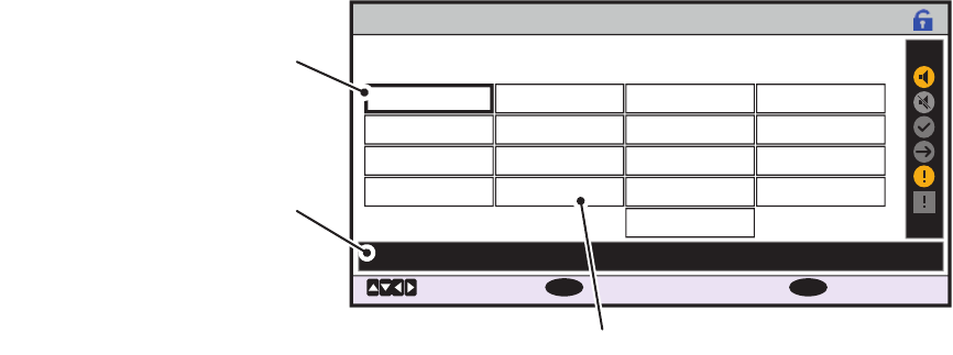
3.4 How to Enable and Disable Alerts
You can enable or disable alerts from the [ALERT ENABLE] menu. Disabling an alert
in this menu will disable all related alerts for the disabled alert.
Note: All alerts are set to [ENABLE] by default.
1. Access the [INITIAL SET] menu, following the procedure outlined in "How to ac-
cess the [INITIAL SET] menu" on page 3-1.
2. Select [ALERT ENABLE], then press the ENT/ACK key.
Active/unacknowledged alerts are displayed with an alert icon next to the alert ID.
3. Select an alert, then press the ENT/ACK key to enable or disable the alert.
Enabled alerts are displayed in green color text, disabled alerts are displayed in
gray color text.
4. Press the MENU/ESC key to return to the [INITIAL SET] menu.
ALERT ENABLE
: BACK
: CURSOR
MENU
: ENABLE/DISABLE
ENT
WARNING1 WARNING2
ENABLE
001 014
026
030
029
005
007
009
010
008
011
025
035
032
002
003
004
DISABLE
ENABLE
HI
LO
001 :
TX MALFUNCTION
DISABLE
: 8 : 0 : 0: 9
Cursor selection is highlighted
Selected alert’s details
Disabled alerts are displayed in gray.
3. SETTING AND ADJUSTMENT
3-7
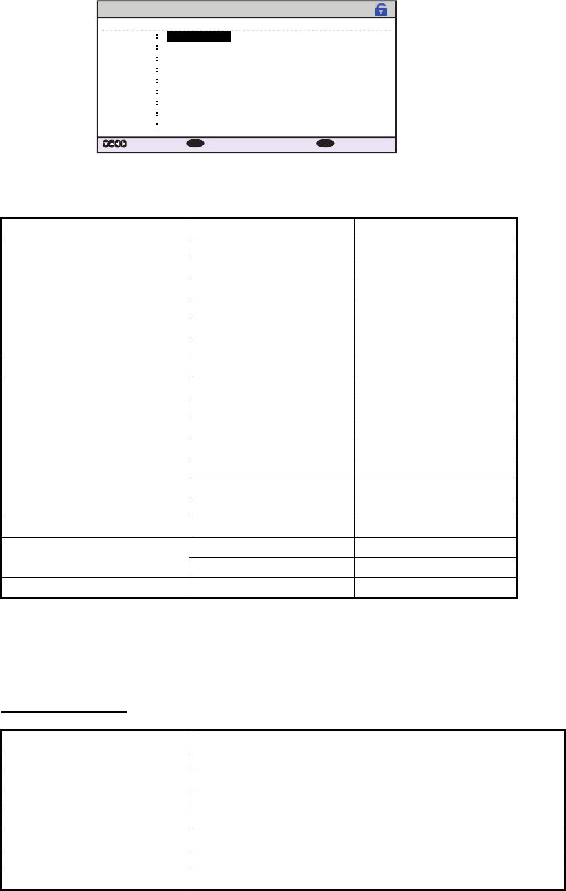
3.5 How to Set Up the I/O Ports
1. Access the [INITIAL SET] menu, following the procedure outlined in "How to ac-
cess the [INITIAL SET] menu" on page 3-1.
2. Select [I/O PORT], then press the ENT/ACK key.
Note: The figure above shows the default settings for all ports.
The available port settings are outlined in the table on the following page.
Note 1: When [MODE] is set to [BEACON] or [MONITOR], speed settings are fixed at
the default setting.
Note 2: For detailed information on data format and related speeds, see "DIGITAL
INTERFACE" on page AP-2.
Mode definitions
PORT MODE SPEED (baud)
COM1 EXT DISPLAY 4800, 38400
LONG RANGE 4800, 38400
BEACON 4800
MONITOR 57600
SERVICE 4800, 38400
DISABLE -
COM2 to COM3 Same as COM1. Same as COM1.
COM4 EXT DISPLAY 4800, 38400
LONG RANGE 4800, 38400
SENSOR 4800, 38400
BEACON 4800
MONITOR 57600
SERVICE 4800, 38400
DISABLE -
COM5 to COM6 Same as COM4. Same as COM4.
SENSOR1 SENSOR Fixed at 4800
DISABLE -
SENSOR2 & SENSOR3 Same as SENSOR1. Same as SENSOR1.
MODE Definition
EXT DISPLAY External display (Radar, ECDIS, Pilot plug, etc.)
LONG RANGE Long range communication device (Inmarsat C, etc.)
SENSOR GPS, Gyrocompass, ROT, etc.
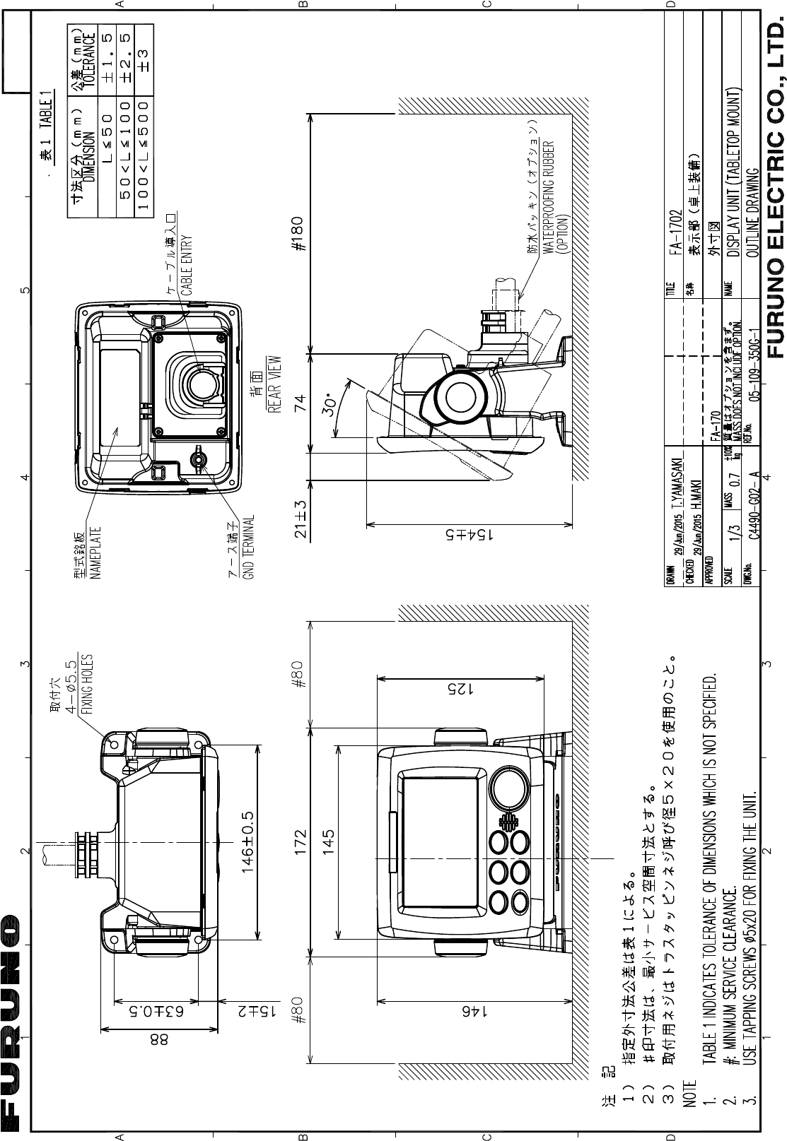
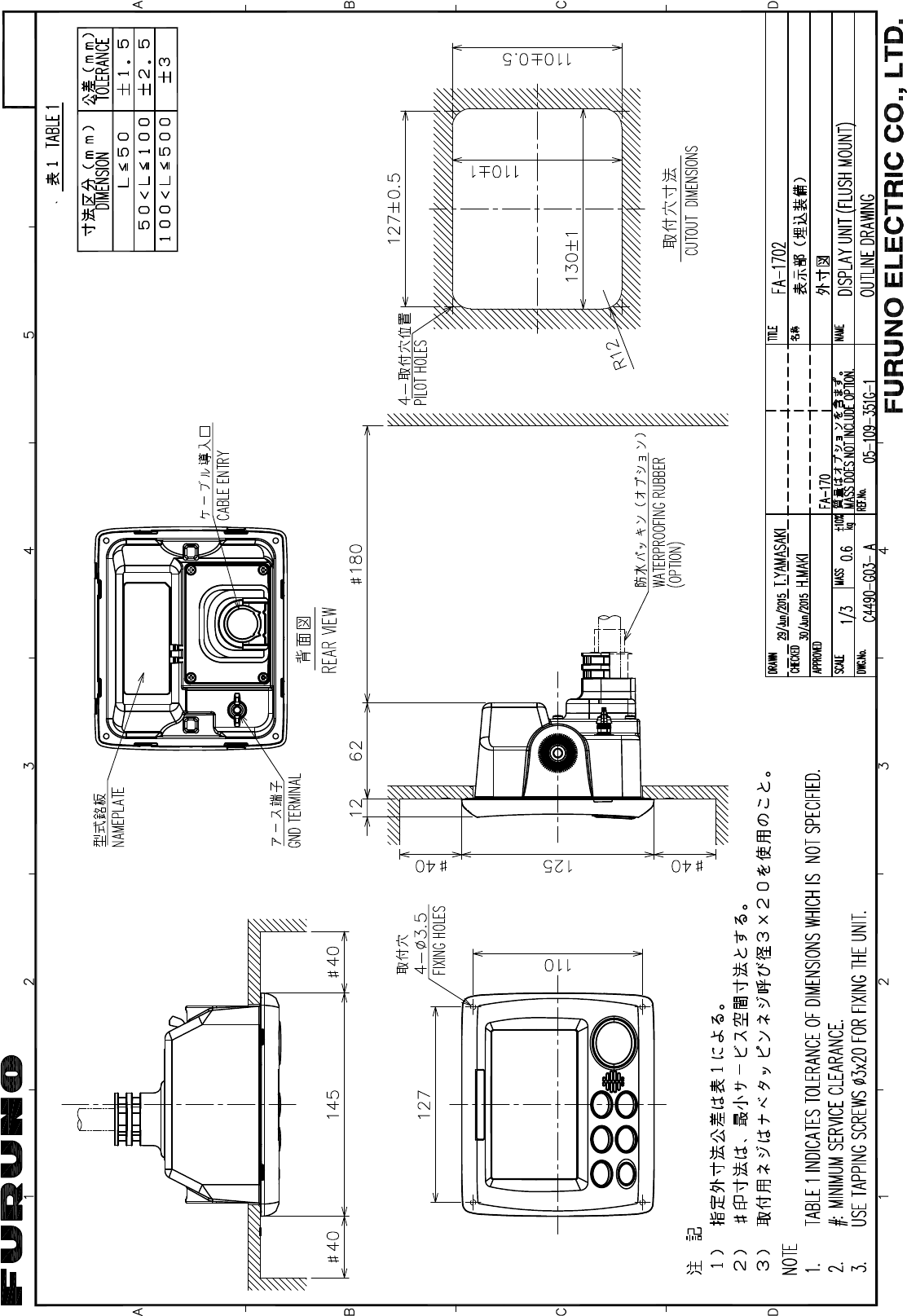
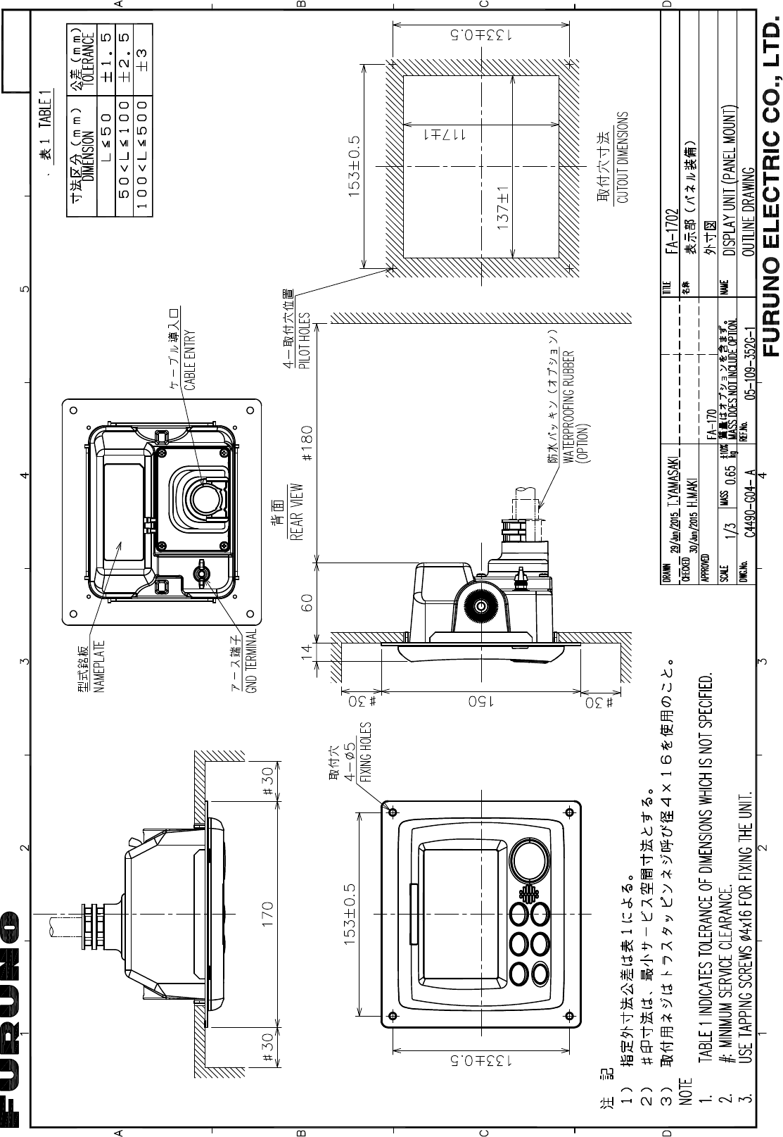
MONITOR For FA-1702 Monitor Unit.
BEACON For Beacon Receiver.
SERVICE For service personnel only. Do not use.
DISABLE Disable the port.
EXT DISPLAY
EXT DISPLAY
EXT DISPLAY
I / O PORT
PORT
COM1
MODE SPEED
38400baud
COM2 EXT DISPLAY
EXT DISPLAY
38400baud
COM3 EXT DISPLAY 38400baud
COM4
SENSOR
SENSOR
SENSOR
38400baud
COM5 38400baud
COM6 38400baud
SENSOR1 4800baud
SENSOR2 4800baud
SENSOR3 4800baud
: SELECT: CURSOR
ENT
: BACK
ENT
3. SETTING AND ADJUSTMENT
3-8
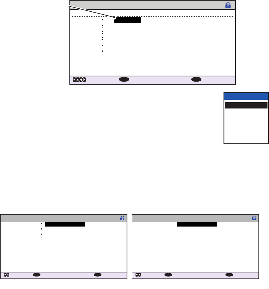
3.5.1 How to set port priority
1. Access the [INITIAL SET] menu, following the procedure outlined in "How to ac-
cess the [INITIAL SET] menu" on page 3-1.
2. Select [PORT PRIORITY], then press the ENT/ACK key.
3. Select the sensor whose priority you want to adjust, then press
the ENT/ACK key. The [SENSOR PORT] pop up window is
displayed.
4. Select the appropriate port, then press the ENT/ACK key.
5. Repeat step 3 to step 4 for other port priorities.
6. Press the MENU/ESC key to return to the [INITAL SET] menu.
3.6 Network Set Up
1. Access the [INITIAL SET] menu, following the procedure outlined in "How to ac-
cess the [INITIAL SET] menu" on page 3-1.
2. Select [NETWORK], then press the ENT/ACK key.
3. [IP ADDRESS] is selected. Press the ENT/ACK key to set the IP address for the
FA-170 within the network.
4. Select and set [SUBNET MASK] and [GATEWAY] in a similar fashion. For
NAVNET networks, go to step 5, for other network types, go to step 12.
5. Select [NAVNET PORT], then press the ENT/ACK key.
6. Input the NAVNET port which this unit is connected to, then press the ENT/ACK
key.
7. Select [HOST NAME], then press the ENT/ACK key.
8. Input the name for this unit within the NAVNET network.
9. Select [AIS INFO], then press the ENT/ACK key.
PORT PRIORITY
PRIORITY
1st
LL/COG/COG
SENSOR1
HDG ROT
2nd SENSOR2
3rd SENSOR3
4th COM4
COM5
COM6
SENSOR3
SENSOR1
SENSOR2
COM6
COM4
COM5
SENSOR3
SENSOR1
SENSOR2
COM6
COM4
COM5
5th
6th
: SELECT: CURSOR
ENT
: BACK
ENT
Selected item is
highlighted in
reverse video.
SENSOR PORT
SENSOR1
SENSOR2
SENSOR3
COM4
COM5
COM6
NETWORK
: CURSOR
: SELECT
172 . 031 . 024 . 004
255 . 255 . 000 . 000
000 . 000 . 000 . 000
AI0001
ENT
: BACK
MENU
IP ADDRESS
SUBNET MASK
GATEWAY
SFI
<SAVE>
NETWORK (NAVNET)
: CURSOR
: SELECT
172 . 031 . 024 . 004
255 . 255 . 000 . 000
000 . 000 . 000 . 000
10000
ENT
: BACK
MENU
IP ADDRESS
SUBNET MASK
GATEWAY
NAVNET PORT
AIS0HOST NAME
ONAIS INFO
OFFZDA INFO
OFFGPS INFO
[OUTPUT AT STARTUP]
<SAVE>
Standard network settings screen. NAVNET network settings screen.

3. SETTING AND ADJUSTMENT
3-9
10. Select [ON] to enable AIS data output to the NAVNET network when this unit is
turned on. Select [OFF] to disable AIS data output when this unit is turned on.
11. Set [ZDA INFO] and [GPS INFO] in the same manner as [AIS INFO], then go to
step 14.
12. Select [SFI], then press the ENT/ACK key.
13. Set the [SFI] (System Function ID), then press the ENT/ACK key.
14. Confirm the settings are correct, then select [<SAVE>] and press the ENT/ACK
key. A confirmation pop up is displayed.
Note: If no changes are made to the settings, [<SAVE>] is not selectable.
15. Select [NO] to change the settings further. Select [YES] to accept the new set-
tings, the unit now shuts down automatically to apply the new settings. When the
unit is shut down, press the power key to restart the unit.
3.7 SERVICE Menu Operations
The [SERVICE] menu is password protected. Contact FURUNO for password details.
The following items require access to the SERVICE for initial
setup:
• ALERT MODE settings
• Network protocol settings
• Restore Factory settings
3.7.1 How to access the SERVICE menu
1. From the [MAIN] menu, select [SERVICE], then press the ENT/ACK key. The
password input pop up appears.
2. Input the password then press the ENT/ACK key.
3.7.2 How to set the alert mode
The alert mode can be set according to the vessel’s configuration. The available alert
modes are: [LEGACY ED.1], [LEGACY ED.2], [ALERT IF1] and [ALERT IF2].
1. Access the [SERVICE] menu referring to the procedure outlined at the start of this
section.
2. Select [ALERT SET], then press the ENT/ACK key.
3. Select [ALERT MODE], then press the ENT/ACK key.
Note: The [OPERATIONAL] setting is
for technical personnel only. Do not
change this setting.
4. Select the appropriate [ALERT MODE]
setting, then press the ENT/ACK key.
Select [ALERT IF1] for vessels configured with AMS, [ALERT IF2] for vessels con-
figured with BAM.
5. Press the MENU/ESC key to return to the [INTIAL SET] menu, or press the DISP
key to close all open menus.
SERVICE
CH SET
AIS SET
ALERT SET
FACTORY SET
OTHER SET
INITIALIZE
1
2
3
4
5
6
TEST
7
MAINTENANCE
8
DEVELOPER
9
ALERT SET
ALERT MODE LEGACY ED.2
OPERATIONAL
1
2
LEGACY ED.1
LEGACY ED.2
ALERT IF1
ALERT IF2

3. SETTING AND ADJUSTMENT
3-10
3.7.3 How to set the network protocol
Set the LAN network protocol according to your vessel’s on-board network. [NAVNET]
protocol should be used where a NavNet series unit is the LAN network hub. Select
[450] for all other LAN networks.
1. Access the [SERVICE] menu referring to the procedure outlined at the start of this
section.
2. Select [OTHER SET], then press the ENT/ACK key.
3. Select [NW PROTOCOL], then press the ENT/ACK key.
Note: The rest of the [OTHER SET]
menu items are for technical personnel
only. Do not change these setting.
4. Select the appropriate protocol, then
press the ENT/ACK key. A confirmation pop up is displayed.
5. Select [YES] to accept the new setting, [NO] to cancel and return to the options.
Selecting [YES] will restart the unit.
3.7.4 How to restore factory settings
This procedure resets the units to factory settings.
Be sure to set all appropriate settings from the [INITIAL SET] menu after completing
this procedure.
1. Access the [SERVICE] menu referring to the procedure outlined at the start of this
section.
2. Select [INTIALIZE], then press the ENT/ACK key.
3. Select [RESTORE FACTORY SET], then press the ENT/ACK key. The confirma-
tion pop up window shown below-right is displayed.
Note: The rest of the [INTIALIZE] menu
items are for technical personnel only.
Do not change these settings.
4. Select the [YES] or [NO] as appropriate,
then press the ENT/ACK key.
[YES]: Accept the new settings and restart the unit.
[NO]: Cancel and return to the options.
OTHER SET
NW PROTOCOL 450
CHECKSUM
1
2
450
NAVNET
ALL C
PASSW
INITIALIZE
RESTORE FACTORY SET
1
2
3
NO
INITIALIZE SETTINGS OK?
YES
AP-1
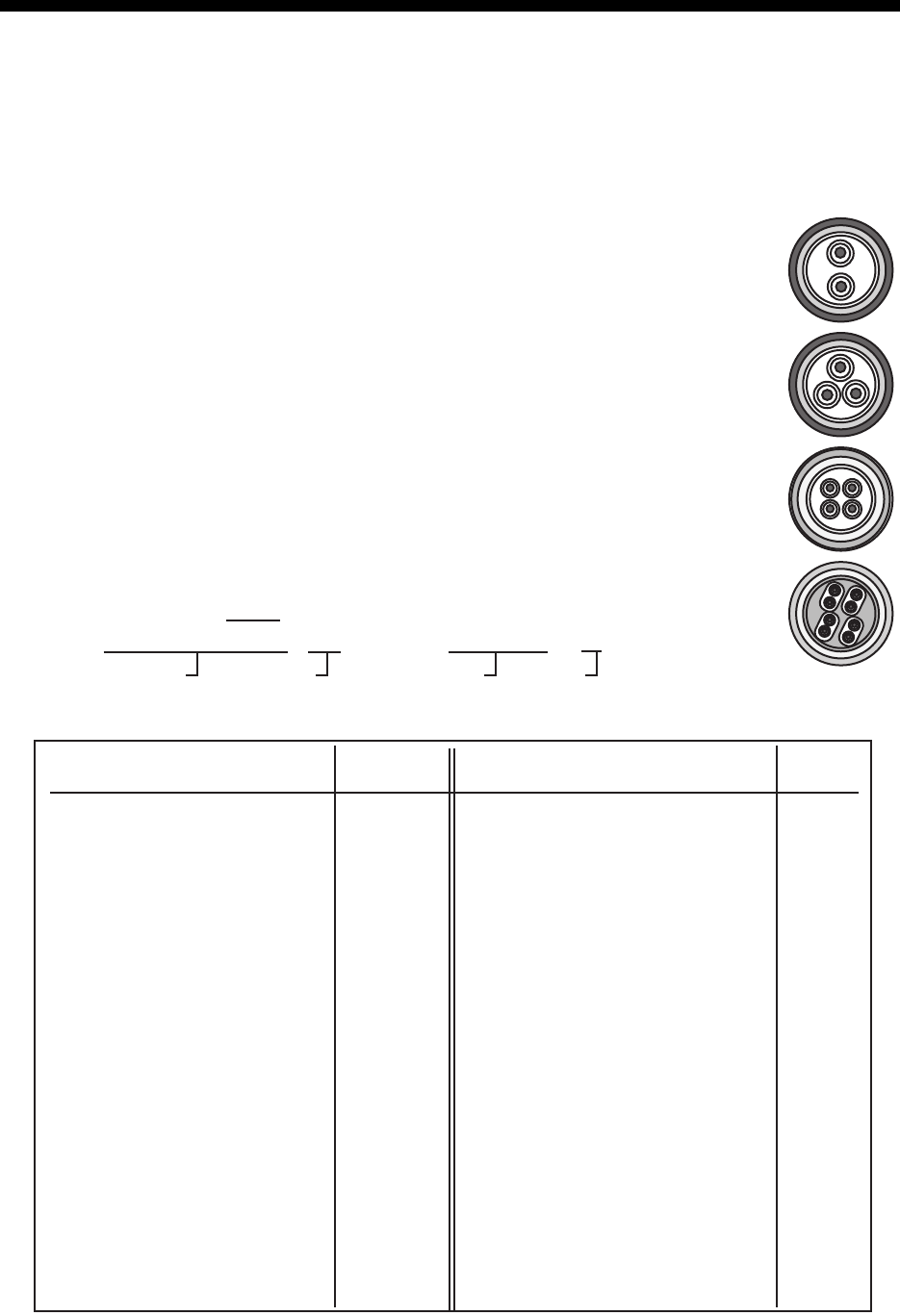
APPENDIX 1 JIS CABLE GUIDE
Core
Type Area Diameter
The following reference table lists gives the measurements of JIS cables commonly used with Furuno products:
TTYCSLA-4
MPYC-4
TPYCY
DPYCY
Cable
Diameter
DPYC-1.5 1.5mm
2
1.56mm 11.7mm
DPYC-2.5 2.5mm
2
2.01mm 12.8mm
DPYC-4 4.0mm
2
2.55mm 13.9mm
DPYC-6 6.0mm
2
3.12mm 15.2mm
DPYC-10 10.0mm
2
4.05mm 17.1mm
DPYCY-1.5 1.5mm
2
1.56mm 13.7mm
DPYCY-2.5 2.5mm
2
2.01mm 14.8mm
DPYCY-4 4.0mm
2
2.55mm 15.9mm
MPYC-2 1.0mm
2
1.29mm 10.0mm
MPYC-4 1.0mm
2
1.29mm 11.2mm
MPYC-7 1.0mm
2
1.29mm 13.2mm
MPYC-12 1.0mm
2
1.29mm 16.8mm
TPYC-1.5 1.5mm
2
1.56mm 12.5mm
TPYC-2.5 2.5mm
2
2.01mm 13.5mm
TPYC-4 4.0mm
2
2.55mm 14.7mm
TPYCY-1.5 1.5mm
2
1.56mm 14.5mm
TPYCY-2.5 2.5mm
2
2.01mm 15.5mm
TPYCY-4 4.0mm
2
2.55mm 16.9mm
TTYCS-1 0.75mm
2
1.11mm 10.1mm
TTYCS-1T 0.75mm
2
1.11mm 10.6mm
TTYCS-1Q 0.75mm
2
1.11mm 11.3mm
TTYCS-4 0.75mm
2
1.11mm 16.3mm
TTYCSLA-1 0.75mm
2
1.11mm 9.4mm
TTYCSLA-1T 0.75mm
2
1.11mm 10.1mm
TTYCSLA-1Q 0.75mm
2
1.11mm 10.8mm
TTYCSLA-4 0.75mm
2
1.11mm 15.7mm
TTYCY-1 0.75mm
2
1.11mm 11.0mm
TTYCY-1T 0.75mm
2
1.11mm 11.7mm
TTYCY-1Q 0.75mm
2
1.11mm 12.6mm
TTYCY-4 0.75mm
2
1.11mm 17.7mm
TTYCY-4S 0.75mm
2
1.11mm 21.1mm
TTYCY-4SLA 0.75mm
2
1.11mm 19.5mm
TTYCYS-1 0.75mm
2
1.11mm 12.1mm
TTYCYS-4 0.75mm
2
1.11mm 18.5mm
TTYCYSLA-1 0.75mm
2
1.11mm 11.2mm
TTYCYSLA-4 0.75mm
2
1.11mm 17.9mm
TTYCSLA-7
0.75mm
2
1.11mm 20.8mm
EX: TTYCYSLA - 4 MPYC - 4
Designation type # of twisted pairs Designation type # of cores
1 2 3 4 5 6 1 2 3 4
Cables listed in the manual are usually shown as Japanese Industrial Standard (JIS). Use the following guide to locate
an equivalent cable locally.
JIS cable names may have up to 6 alphabetical characters, followed by a dash and a numerical value (example:
DPYC-2.5).
For core types D and T, the numerical designation indicates the cross-sectional Area (mm2) of the core wire(s) in the
cable.
For core types M and TT, the numerical designation indicates the number of core wires in the cable.
1. Core Type
D: Double core power line
T: Triple core power line
M: Multi core
TT: Twisted pair communications
(1Q=quad cable)
2. Insulation Type
P: Ethylene Propylene
Rubber
3. Sheath Type
Y: PVC (Vinyl)
4. Armor Type
C: Steel
5. Sheath Type
Y: Anticorrosive vinyl
sheath
6. Shielding Type
S: All cores in one sheath
-S: Indivisually sheathed cores
SLA: All cores in one shield, plastic
tape w/aluminum tape
-SLA: I
ndividually shielded cores,
plastic tape w/aluminum tape
Core
Type Area Diameter
Cable
Diameter
AP-2
APPENDIX 2 DIGITAL INTERFACE
IEC61162-1/2 data sentences
IEC61162-1/2 format data is input or output from the data port COM1-COM6.
The table below shows the input/output data specifications for the transponder unit (FA-1701).
Priority for input data/sentences
Digital Interface (IEC 61162-1 Edition 4, IEC 61162-2)
Sentence data
Input sentences
ABM, ACA, ACK, ACM, ACN, AIQ, AIR, BBM, DTM, EPV, GBS, GGA, GLL, GNS, HBT, HDT,
LRF, LRI, OSD, PIWWIVD, PIWWSPW, PIWWSSD, PIWWVSD, RMC, ROT, SPW, SSD, THS,
VBW, VSD, VTG
Output sentences
ABK, ACA, ACS, ALC, ALF, ALR, ARC, EPV, HBT, LRI, LRF, LR1, LR2, LR3, NAK, SSD, TRL,
TXT, PIWWIVD, PIWWSPR, PIWWSSD, PIWWVSD, VDM, VDO, VER, VSD
Port Menu setting Input/Output Data format Speed
COM1 to
COM3
EXT DISPLAY Input/output IEC61162-2 38400bps
LONG RANGE Input/output IEC61162-2 38400bps
BEACON Input RTCM SC104 4800bps
COM4 to
COM6
EXT DISPLAY Input/output IEC61162-2 38400bps
LONG RANGE Input/output IEC61162-2 38400bps
SENSOR Input IEC61162-2 38400bps
BEACON Input RTCM SC104 4800bps
SENSOR1 to
SENSOR3
SENSOR Input IEC61162-1 4800bps
Sentence (Priority) Contents
GNS>GLL>GGA>RMC Position
VBW>RMC>VTG>OSD Speed over ground
RMC>VTG>OSD Course over ground
THS>HDT>OSD>AD-10 format Heading
ROT> Calculated value Rate of turn
APPENDIX 2 DIGITAL INTERFACE
AP-3
Transmission intervals
Load requirements as listener
Isolation: Provided
Input Impedance: Input Impedance: 110 ohms (130K ohms without jumper plug)
Max. Voltage: ±14 V to GNDiso
Threshold: ±0.2 V (A-B)
Output drive capability
Differential driver output
R=50 ohm 2 v min.
R=27 ohm 1.5 V min.
Driver short-circuit current
60 mA min. 150 mA max.
Data transmission
Data is transmitted in serial asynchronous form in accordance with the standard referenced in 2.1
of IEC 61162-1/2. The first bit is a start bit and is followed by data bits, least-significant-bit as il-
lustrated below.
The following parameters are used:
Baud rate: 38.4 Kbps /4800 bps
Data bits: 8 (D7 = 0), parity none
Stop bits: 1
Sentence Interval Sentence Interval
ABK With each event ACA When requested, or with each
event
ACS Transmitted after ACA ALC 30 seconds
ALF When requested, or with each
event
ALR 30 seconds
ARC With each event EPV When requested, or with each
event
HBT 50 seconds LR1 With each event
LR2 With each event LR3 With each event
LRF With each event LRI With each event
NAK With each event PIWWIVD When requested, or with each
event
PIWWSPR When requested, or with each
event
PIWWSSD When requested, or with each
event
PIWWVSD When requested, or with each
event
SSD When requested, or with each
event
TRL When requested, or with each
event
TXT When requested, or with each
event
VDM With each event VDO 1 second or with each event
VER When requested, or with each
event, or powered on
VSD When requested, or with each
event
D0 D1 D2 D3 D4 D5 D6 D7
Start
bit
Stop
bit
Data bits
IEC61162-1:Edition 4.0 2010-11
IEC61162-2:First Edition 1998-09
IEC61162-450:Edition 1.0 2011-06
APPENDIX 2 DIGITAL INTERFACE
AP-4
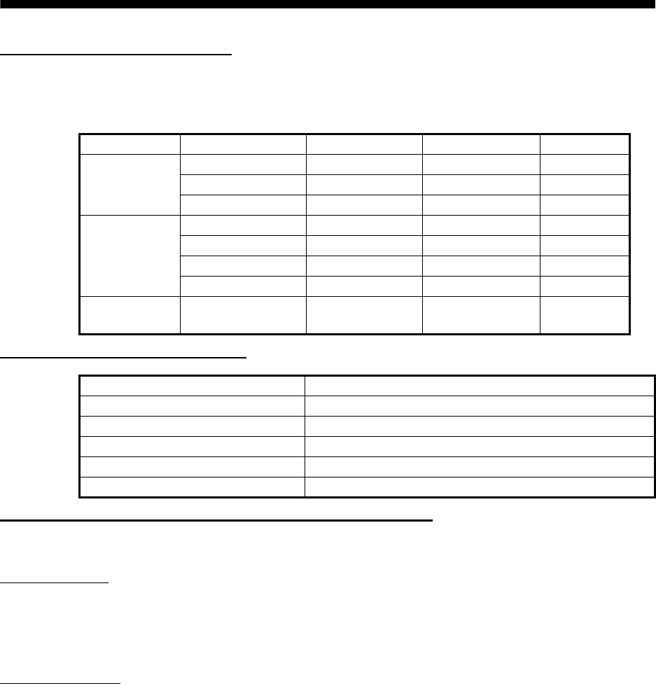
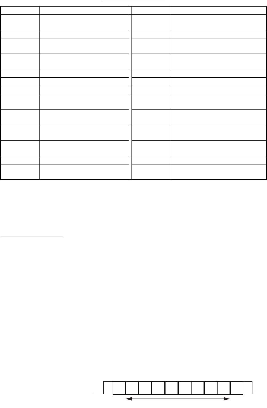
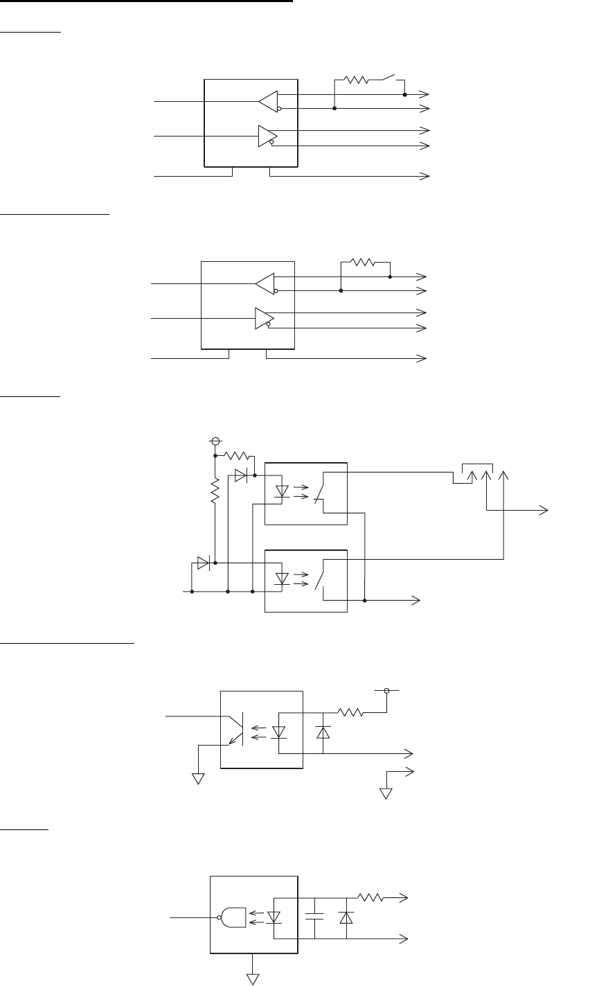
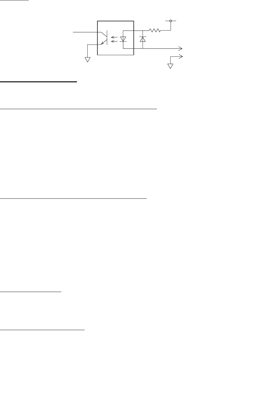
Serial & contact interface I/O circuit
COM1, 2
COM3 to COM6
External
Alarm Acknowledge
Sensor
ADM2587E
GND1-4
RD
TD
120Ω
GND5-8
COM1_RD_TERM
COM1_RD_B
COM1_RD_A
COM1_TD_B
COM1_TD_A
COM1_GND_ISO
GND
ADM2587E
GND1-4
RD
TD
120Ω
GND5-8
COM3_RD_B
COM3_RD_A
COM3_TD_B
COM3_TD_A
COM3_GND_ISO
GND
TLP176
TLP4176
EXT_ALM
P3.3V
EXT_ALM_C
EXT_ALM_H
EXT_ALM_NO_H
EXT_ALM_NC_H
TLP185
RD
P12V
ALM_ACK_H
ALM_ACK_C
1.2kΩ
PC400
RD
SENSOR1_C
SENSOR1_H
490Ω
GND
APPENDIX 2 DIGITAL INTERFACE
AP-5
Blue Sign
Sentence description
Input sentences
ABM - Addressed binary and safety related message
ACA - AIS regional channel assignment message
ACK - Acknowledge
ACN(ACM) - Alert command
TLP185
RD
P12V
BLUESIGN_H
BLUESIGN_C
1.2kΩ
!**ABM, x, x, x, xxxxxxxxx, x, x.x, s--s, x, *hh<CR><LF>
1 2 3 4 5 6 7 8
1. Total number of sentences needed to transfer the message (1 to 9)
2. Message sentence number (1 to 9)
3. Message sequence identifier (0 to 3)
4. The MMSI of destination AIS unit for the ITU-R M.1371 message (9 digits, NULL)
5. AIS channel for broadcast of the radio message (0 to 3, NULL)
6. VDL message number (6, 12, 25, 26, 70, 71, NULL), see ITU-R M.1371
7. Encapsulated data (1 to 63 bytes)
8. Number of fill-bits (0 to 5)
9. Channel B
10. Channel B bandwidth
11. Tx/Rx mode control
12. Power level control
13. Information source
14. In-use flag
15. Time of “in-use” change
1. Sequence number (0 to 9, NULL)
2. Region Northeast corner latitude (N, S, NULL)
3. Region Northeast corner longitude (E, W, NULL)
4. Region Southwest corner latitude (N, S, NULL)
5. Region Southwest corner longitude (E, W, NULL)
6. Transition Zone Size
7. Channel A
8. Channel A bandwidth
$**ACA,x,IIII.lI, a,yyyyy.yy,a,IIII.II,a,yyyyy.yy,a,x,xxxx,x,xxxx,x,x,x,a,x,hhmmss.ss,*hh<CR><LF>
1 2 3 4 5 6 7 8
9 1011121314
15
$**ACK,xxx,*hh<CR><LF>
1
1. Local alarm number (identifier) (000 to 999)
$**ACN(ACM),hhmmss.ss,aaa,x.x,x.x,c,a*hh<CR><LF>
1 2 3 4 5 6
1. Time
2. Manufacturer mnemonic code
3. Alert Identifier
4. Alert Instance (1
to
999999)
5. Alert command
(A=acknowledge, Q=request/repeat information, O=responsibility transfer S=silence)
6. Sentence status flag

APPENDIX 2 DIGITAL INTERFACE
AP-6
AIQ - Query sentence
AIR - AIS interrogation request
BBM - AIS broadcast binary message.
DTM - Datum reference
EPV - Command or report equipment property value
$**AIQ,ccc,*hh<CR><LF>
1
1. Information requested (ACA*3, IWWIVD*1*2, IWWVSD*1*2, IWWSSD*1*2,
PIWWIVD*2, PIWWVSD*2, PIWWSSD*2, SSD, TRL, TXT, VER, VSD)
*1: Compatible with Tresco Inland ECDIS viewer.
*2: Valid only when AIS is in INLAND mode.
*3: When ACA is requested, ACS is also sent immediately after ACA.
$**AIR,xxxxxxxxx,x.x,x,x.x,x,xxxxxxxxx,x.x,x, a, x.x, x.x, x.x *hh<CR><LF>
1 2 3 4 5 6 7 8 9 10 11 12
1. MMSI of interrogated station 1
2. ITU-R M.1371 message requested from station 1
3. Message sub-section
4. ITU-R M.1371 second message requested from station 1
5. Message sub-section
6. MMSI of interrogated station 2
7. ITU-R M.1371 message requested from station 2
8. Message sub-section
9. Channel used on request
10. No use. Response slot for Message ID 1.1 of Message 15
11. No use. Response slot for Message ID 1.2 of Message 15
12. No use. Response slot for Message ID 2.1 of Message 15
$**BBM,x,x,x,x,xx,s--s,x,*hh<CR><LF>
12 3 4 5 6 7
1. Total number of sentences needed to transfer the message (1
to
9)
2. Sentence number (1
to
9)
3. Sequential Message identifier (0
to
9)
4. AIS channel for broadcast of the radio message
5. VDL message no. (8, 14, 25, 26, 70 or 71, NULL)
6. Encapsulated data
7. Number of fill-bits, 0 to 5
$**DTM,ccc,a,x.x,a,x.x,a,x.x,ccc,*hh<CR><LF>
1 2 3 4 5 6 7 8
1. Local datum (W84=WGS84, W72=WGS72, S85=SGS85, P90=PE90,
User defined=999, IHO datum code, NULL)
2. Local datum subdivision code (NULL or one character)
3. Lat offset, min (-59.99999 to 59.99999)
4. N/S
5. Lon offset, min (-59.99999 to 59.99999)
6. E/W
7. Altitude offset, meters (no use)
8. Reference datum (W84=WGS84, W72=WGS72, S85=SGS85, P90=PE90)
$ **EPV,s,cc,c--c,x.x,c--c*hh<CR><LF>
1 2 3 4 5
1. Sentence status flag (C=Configuration command)
2. Equipment type
3. Unique indentifier (MMSI)
4. Property identifier for property to be set
5. Value of property to be set

APPENDIX 2 DIGITAL INTERFACE
AP-7
GBS - GNSS satellite fault detection
GGA - Global positioning system (GPS) fix data
GLL - Geographic position - latitude/longitude
$**GBS, hhmmss.ss, x.x, x.x, x.x, xx, x.x, x.x, x.x h, h, *hh<CR><LF>
1 2 3 4 5 6 7 8 9 10
1. UTC time of GGA or GNS fix associated with this sentence
2. Expected error in latitude (0.0 to 999.9)
3. Expected error in longitude (0.0 to 999.9)
4. Expected error in altitude (no use)
5. ID number of most likely failed satellite (no use)
6. Probability of missed detection for most likely failed satellite (no use)
7. Estimate of bias in meters on most likely failed satellite (no use)
8. Standard deviation of bias estimate (no use)
9. GNSS system ID
10 GNSS signal ID
$**GGA, hhmmss.ss, llll.ll, a, yyyyy.yy, a, x, xx, x.x, x.x, M, x.x, M, x.x, xxxx,*hh<CR><LF>
1 2 3 4 5 6 7 8 9 10 11 12 13 14
1. UTC of position (0.00 to 235959.99)
2. Latitude (0.00000 to 9000.00000)
3. N/S
4. Longitude (0.00000 to 18000.00000)
5. E/W
6. GPS quality indicator
7. Number of satellites in use,00 to 12, may be different from the number in view (no use)
8. Horizontal dilution of precision (no use)
9. Antenna altitude above/below mean sea level (geoid) (no use)
10. Units of antenna altitude, m (no use)
11. Geoidal separation (no use)
12. Units of geoidal separation, m (no use)
13. Age of differential GPS data (no use)
14. Differential reference station ID, 0000 to 1023 (no use)
$**GLL,llll.lll,a,yyyyy.yy,a,hhmmss.ss,a,x,*hh<CR><LF>
1 2 3 4 5 6 7
1. Latitude (0.00000
to
9000.00000)
2. N/S
3. Longitude (0.00000
to
18000.00000)
4. E/W
5. UTC of position (0.00 to 235959.99)
6. Status (A=data valid)
7. Mode indicator (A=Autonomous, D=Differential, R=Real time kinematic,
F=Float RTK, P=Precise)

APPENDIX 2 DIGITAL INTERFACE
AP-8
GNS - GNSS fix data
HBT - Heart beat supervision
HDT - Heading - true
LRF - Long-range function
$**GNS,hhmmss.ss,llll.ll,a,IIIII.II,a,c--c,xx,x.x,x.x,x.x,x.x,x.x,a*hh<CR><LF>
1 2 3 4 5 6 7 8 9 10 11 12 13
1. UTC of position (0.00 to 235959.99)
2. Latitude (0.00000
to
9000.00000)
3. N/S
4. Longitude (0.00000
to
18000.00000)
5. E/W
6. Mode indicator (A=Autonomous, D=Differential, E=Estimated Mode, F=Float RTK, M=Manual
Input Mode, N=No fix, P=Precise, R=Real Time Kinematic, S=Simulator Mode)
7. Total number of satellites in use (Not used)
8. HDOP (Not used)
9. Antenna altitude, meters (Not used)
10. Geoidal separation (Not used)
11. Age of differential data (Not used)
12. Differential reference station ID (Not used)
13. Navigational status indicator (S=Safe; C=Caution; U=Unsafe; V=Not valid)
$--HBT, x. x, A, x*hh<CR><LF>
1 2 3
1. Configured repeat interval (1 to 999, NULL)
2. Equipment status (A/V)
3. Sequential sentence identifier (0 to 9, NULL)
$**HDT, xxx.x,T*hh<CR><LF>
1 2
1. Heading, degrees (0.000 to 359.999)
2. True (T, NULL)
$**LRF,x,xxxxxxxxx,c--c,c--c,c--c*hh<CR><LF>
1 2 3 4 5
1. Sequence number (0
to
9)
2. MMSI of requester
3. Name of requester (1
to
20 characters, NULL)
4. Function request
(1
to
26 characters (Preceded by A, B, C, E, F, I ,O, P, U, W), NULL)
A : Ship’s name, call sign and IMO No.
B : Date and time of message composition
C : Position
E : Course Over Ground
F : Speed Over Ground
I : Destination and Estimated Time of Arrival (ETA)
O : Draught
P : Ship/Cargo
U : Ship’s length, breadth and type
W : Persons on board
5. Function reply status
(1 to 26 characters (Preceded by 2, 3, 4), NULL)
2: Information available and provided in the following LR1, LR2, LR3 sentence;
3: Information not available from AIS unit;
4: Information is available but not provided (i.e. restricted access determined by the ship’s master)

APPENDIX 2 DIGITAL INTERFACE
AP-9
LRI - Long-range interrogation
OSD - Own ship data
RMC - Recommended minimum specific GPS/TRANSIT data
ROT - Rate of turn
SPW - Security password sentence
$**LRI,x,a,xxxxxxxxx,xxxxxxxxx,llll.ll,a,yyyyy.yy,a,llll.ll,a,yyyyy.yy,a*hh<CR><LF>
1 2 3 4 5 6 7 8
1. Sequence number (0 to 9)
2. Control flag
3. MMSI of requestor
4. MMSI of destination
5. Latitude - N/S for north-east corner (0000.0000 to 9000.0000, NULL)
6. Longitude - E/W for north-east corner (0000.0000 to 18000.0000, NULL)
7. Latitude - N/S for south-west corner (0000.0000 to 9000.0000, NULL)
8. Longitude - E/W for south-west corner (0000.0000 to 18000.0000, NULL)
$**OSD, x.x, A, x.x, a, x.x, a, x.x, x.x, a *hh<CR><LF>
1 2 3 4 5 6 7 8 9
1. Heading, degrees true (0.00
to
359.99)
2. Heading status (A=data valid)
3. Vessel course, degrees true (0.00
to
359.99)
4. Course reference (B=Bottom tracking log, R=Radar tracking (of fixed target),
P=Positioning system ground reference)
5. Vessel speed (0.00
to
999.999)
6. Speed refereence, (B/R/P) (See 4.)
7. Vessel set, degrees true, manually entered (Not used)
8. Vessel drift (speed), manually entered (Not used)
9. Speed units (K=km/h N=Knots S=statute miles/h)
$**RMC, hhmmss.ss, A, llll.ll, a, yyyyy.yy, a, x.x, x.x, ddmmyy, x.x, a, a, a *hh<CR><LF>
1 2 3 4 5 6 7 8 9 10
11 12 13
1. UTC of position fix (0.00 to 235959.99)
2. Status (A=data valid)
3. Latitude (0000.0000 to 9000.0000)
4. N/S
5. Longitude (0000.0000 to 18000.0000)
6. E/W
7. Speed over ground, knots (0.00 to 999.99)
8. Course over ground, degrees true (0.00 to 359.99)
9. Date (010100 to 311299)
10. Magnetic variation, degrees E/W (Not used)
11. E/W (Not used)
12. Mode indicator (A= Autonomous, D= Differential, F=Float RTK, P=Precise, R=Real time
kinematic)
13. Navigational status indication (S=Safe; C=Caution; U=Unsafe; V=Navigational status not
valid, equipment is not providing navigational status indication, NULL)
$--ROT,x.x,A*hh<CR><LF>
1 2
1. Rate of turn, deg/min, "-"=bow turns to port (-9999.99
to
9999.99)
2. Status (A=data valid)
$ **SPW,ccc,c--c,x,c--c*hh<CR><LF>
1 2 3 4
1. Password protected sentence
2. Unique identifier (MMSI=000000000 to 999999999, NULL)
3. Password level (1=User defined,2=Administator)
4. Password (Maximum 32 characters, text only)

APPENDIX 2 DIGITAL INTERFACE
AP-10
SSD - AIS ship static data
THS - True heading and status
VBW - Dual ground/water speed
VSD - AIS voyage static data
VTG - Course over ground and ground speed
$**SSD,c--c,c--c,xxx,xxx,xx,xx,c, aa*hh<CR><LF>
1 2 3 4 5 6 7 8
1. Ship's call sign (1 to 7 characters, NULL)
2. Ship's name (1 to 20 characters, NULL)
3. Pos. ref. point distance, "A," from bow (0 to 511 Meters, NULL)
4. Pos. ref. point distance, "B," from stern (0 to 511 Meters, NULL)
5. Pos. ref. point distance, "C," from port beam (0 to 63 Meters, NULL)
6. Pos. ref. point distance, "D," from starboard beam (0 to 63 Meters, NULL)
7. DTE indicator flag
8. Source identifier (2 characters, NULL)
$--THS, x.x, a *hh<CR><LF>
1 2
1. Heading, degrees true (0.00
to
359.99)
2. Mode indicator (A=Autonomous)
$**VBW,x.x,x.x,x,x.x,x.x,x,x.x,x,x.x,x,*hh<CR><LF>
1 2 3 4 5 6 7 8 9 10
1. (No use) Longitudinal water speed, knots (-9999.99 to 9999.99)
2. (No use) Transverse water speed, knots (-9999.99 to 9999.99)
3. (No use) Status: water speed, A=data valid V=data invalid
4. Longitudinal ground speed, knots (-999.999 to 999.999)
5. Transverse ground speed, knots (-999.999 to 999.999)
6. Status: ground speed (A=data valid, NULL)
7. (No use) Stern transverse water speed, knots (-9999.99 - 9999.99)
8. (No use) Status: stern water speed, A=data valid V=data invalid
9. (No use) Stern transverse ground speed, knots (-9999.99 - 9999.99)
10. (No use) Status: stern ground speed, A=data valid V=data invalid
$--VSD,x.x,x.x,x.x,c--c,hhmmss.ss,xx,xx,x.x,x.x*hh<CR><LF>
1 2 3 4 5 6 7 8 9
1. Type of ship and cargo category (0 to 255, NULL)
2. Maximum present static draught (0 to 25.5m, NULL)
3. Persons on-board (0 to 8191, NULL)
4. Destination (1 to 20 characters, NULL)
5. Estimated UTC of arrival at destination (0 to 235959.99, NULL)
6. Estimated day of arrival at destination (00 to 31(UTC), NULL)
7. Estimated month of arrival at destination (00 to 12(UTC), NULL)
8. Navigational status (0 to 15, NULL)
9. Regional application flags (0 to 15, NULL)
$--VTG, x.x, T, x.x, M, x.x, N, x.x, K, a,*hh <CR><LF>
1 2 3 4 5 6 7 8 9
1. Course over ground, degrees (0.00 to 359.99)
2. T=True (fixed)
3. (No use) Course over ground, degrees (0.0 to 359.99)
4. (No use) M=Magnetic (fixed)
5. Speed over ground, knots (0.00 to 999.99)
6. N=Knots (fixed)
7. Speed over ground (0.00 to 999.99)
8. K=km/h (fixed)
9. Mode indicator (
A=Autonomous mode, D=Differential mode, P=Precise)

APPENDIX 2 DIGITAL INTERFACE
AP-11
Output sentences
ABK - AIS addressed and binary broadcast acknowledgment
ACA - See “ACA - AIS regional channel assignment message” on page AP-5.
ACS - Channel management information source
ALC - Cyclic alert list
$**ABK,xxxxxxxxx,x,x.x,x,x,*hh<CR><LF>
1 2 3 4 5
1. MMSI of the addressed AIS unit
2. AIS channel of reception
3. Message ID
4. Message sequence number
5. Type of acknowledgement
$**ACS,x,xxxxxxxxx,hhmmss.ss,xx,xx,xxxx,*hh<CR><LF>
1 2 3 4 5 6
1. Sequence number (0 to 9)
2. MMSI of originator (000000000 to 999999999, NULL)
3. UTC at receipt of channel management information (000000 to 235959, NULL)
4. UTC day (01 to 31, NULL)
5. UTC month (01 to 12, NULL)
6. UTC year (2010 to 2060, NULL)
$**ALC,xx,xx,xx,x.x, aaa,x.x,x.x,x.x,·········,*hh<CR><LF>
1 2 3 4 5 6 7 8 9
1. Total number of sentences for this message (01 to 99)
2. Sentence number (01 to 99)
3. Sequential message identifier (00 to 99)
4. Number of alert entries
5. Manufacturer mnemonic code
6. Alert identifier
7. Alert instance
8. Revision counter
9. Additional Alert entries (see Note)
Note: Alert entry 0 - n: Each alert entry consists of
- Manufacturer Identifier (see ALF Manufactuer Identifier)
- Alert Identifier (see ALF Alert identifier)
- Alert instance (see ALF instance)
- Revision counter (see ALF revision counter)
Alert entry 1
See Note

APPENDIX 2 DIGITAL INTERFACE
AP-12
ALF - Alert sentence
ALR - Set state
ARC - Alert command refused
EPV - Command or report equipment property value”
HBT - Heart beat supervision
$**ALF,x,x,x,hhmmss.ss,a,a,a,aaa,x.x,x.x,x.x,x,c--c,*hh<CR><LF>
1 2 3 4 5 6 7 8 9 10 11 12 13
1. Total number of ALF sentences for this message (1, 2)
2. Sentence number (1, 2)
3. Sequential message identifier (0 to 9)
4. Time of last change (hhmmss.ss, NULL)
5. Alert category (B=Category B, C=Category C, NULL)
6. Alert priority (W=Warning, C=Caution, NULL)
7. Alert state
V=active - unacknowledged, S=active - silenced,
A=active - acknowledged or active, O=active - responsibility transferred,
U=rectified - unacknowledged, N=normal, NULL
8. Manufacturer mnemonic code (FEC, NULL)
9. Alert identifier (001 to 999999)
10. Alert instance (NULL)
11. Revision counter (1 to 99)
12. Escalation counter (0 to 9)
13. Alert text
$**ALR,hhmmss.ss,xxx,A,A,c—c,*hh<CR><LF>
1 2 3 4 5
1. Time of alarm condition change, UTC
2. Unique alarm number (identifier) at alarm source (000 to 999, NULL)
3. Alarm condition (A=threshold exceeded, V=not exceeded)
4. Alarm acknowledge state (A=acknowledged, V=not acknowledged)
5. Alarm description text (alphanumeric)
$**ARC,hhmmss.ss,aaa,x.x,x.x,c*hh<CR><LF>
1 2 3 4 5
1. Time
2. Manufacturer mnemonic code
3. Alert identifier (001 to 99999)
4. Alert instance (NULL)
5. Refused alert command
A=acknowledge
Q=request/repeat information
O=responsibility transfer
S=silence
$ **EPV,s,cc,c--c,x.x,c--c*hh<CR><LF>
1 2 3 4 5
1. Sentence status flag (Fixed: R=Response)
2. Equipment type (Fixed: AI)
3. Unique indentifier (MMSI: 00000000 to 999999999)
4. Property identifier for property to be set (106 to 113)
5. Value of property to be set
$--HBT, x. x, A, x*hh<CR><LF>
1 2 3
1. Configured repeat interval (50)
2. Equipment status (A)
3. Sequential sentence identifier (0 to 9)

APPENDIX 2 DIGITAL INTERFACE
AP-13
LRF - See “LRF - Long-range function” on page AP-8.
LR1 - Long-range reply with destination for function request “A”
LR2 - Long-range reply for function requests “B, C, E, and F”
LR3 - Long-range reply for function requests “I, O, P, U and W”
LRI - See “LRI - Long-range interrogation” on page AP-9.
NAK - Negative acknowledgment
SSD - See "SSD - AIS ship static data" on page AP-10.
$**LR1,x,xxxxxxxxx,xxxxxxxxx,c--c,c--c,xxxxxxxxx*hh<CR><LF>
1 2 3 4 5 6
1. Sequence number
2. MMSI of responder
3. MMSI of requester (reply destination)
4. Ship's name (1 to 20 characters)
5. Call sign (1 to 7 characters)
6. IMO number, (9-digit number)
$**LR2,x,xxxxxxxxx,xxxxxx,hhmmss.ss,llll.ll,a,yyyyy.yy,a,x.x,T,x.x,N*hh<CR><LF>
1 2 3 4 5 6 7 8
1. Sequence number
2. MMSI of responder
3. Date (ddmmyy)
4. UTC of Position
5. Latitude - N/S
6. Longitude - E/W
7. Course over ground, degrees True
8. Speed over ground, Knots
$**LR3,x,xxxxxxxxx,c--c,xxxxxx,hhmmss.ss,x.x,cc,x.x,x.x,cc,x.x*hh<CR><LF>
1 2 3 4 5 6 7 8 9 10 11
1. Sequence number
2. MMSI of responder
3. Voyage destination (1 to 20 characters)
4. ETA date (ddmmyy)
5. ETA time
6. Draught
7. Ship/cargo
8. Ship length
9. Ship breadth
10. Ship type
11. Persons (0 to 8191)
$**NAK,cc,ccc,c--c,x.x,c--c *hh<CR><LF>
1 2 3 4 5
1. Talker identifier
2. Affected sentence formatter
3. Unique identifier
4. Reason code for negative ackowledgment (0=Query functionality not supported, 1=Sentence
formatter not supported, 2=Sentence formatter supported, but not enabled; 3=Senetence
formatter supported and enabled, but temporarily unavailable; 4=Sentence formatter
supported, but query for this sentence formatter is not supported; 5=Access denied, for
sentence formatter requested; 6=Sentence not accepted due to bad checksum;
7=Sentence not accepted due to listener processing issue; 8,9=Reserved for future use;
10=Cannot perform the requested operation; 11=cannot fulfill request or command because
of a problem with a data field in the sentence; 12 to 48=Reserved for future use; 49=Other
reason as described in field 5.)
5. Negative acknowledgment’s descriptive text

APPENDIX 2 DIGITAL INTERFACE
AP-14
TRL - AIS transmitter non functioning log
TXT - Text transmission
VDM - VHF data-link message
VDO - AIS VHF data-link own-vessel report
VER - Version
VSD - See "VSD - AIS voyage static data" on page AP-10.
$**TRL,x.x,x.x,x,xxxxxxxx,hhmmss.ss,xxxxxxxx,hhmmss.ss,x,*hh<CR><LF>
1 2 3 4 5 6 7 8
1. Total number of log entries (0 to 10)
2. Log entry number (1 to 10, NULL)
3. Sequential message indentifier (0 to 9, NULL)
4. Switch off date (ddmmyyyy, NULL)
5. Switch off UTC time (000000 to 235959, NULL)
6. Switch on date (ddmmyy, NULL)
7. Switch on UTC time (000000 to 235959, NULL)
8. Reason code (1 to 5, NULL) 1=power off, 2=silent mode, 3=transmission switched off by
channel management command, 4=equipment malfunction, 5=invalid configuration.
$--TXT,xx,xx,xx,c--c*hh<CR><LF>
1 2 3 4
1. Total number of sentences (01 to 99)
2. Sentence number (01 to 99)
3. Text identifier
4. Text message
!AIVDM,x,x,x,a,s--s,x,*hh<CR><LF>
1 2 3 4 5 6
1. Total number of sentences needed to transfer the message (1 to 9)
2. Message sentence number (1 to 9)
3. Sequential message identifier (0 to 9, NULL)
4. AIS channel Number (A, B)
5. Encapsulated ITU-R M.1371 radio message (1 - 63 bytes)
6. Number of fill-bits (0 to 5)
!AIVDO,x,x,x,x,s--s,x,*hh<CR><LF>
1 2 3 4 5 6
1. Total number of sentences needed to transfer the message (1 to 9)
2. Message sentence number (1 to 9)
3. Sequential message identifier (0 to 9, NULL)
4. AIS channel Number (A, B, C, D, NULL)
5. Encapsulated ITU-R M.1371 radio message (1 to 63 bytes)
6. Number of fill-bits (0 to 5)
$AIVER,x,x,aa,c-c,c-c,c-c,c-c,c-c,c-c,x,*hh<CR><LF>
1 2 3 4 5 6 7 8 9 10
1. Total number of sentences needed (1 to 9)
2. Sentence number (1 to 9)
3. Device type (AI)
4. Vendor ID
5. Unique Identifier
6. Manufacturer serial number
7. Model code (product code)
8. Software revision
9. Hardware revision
10. Sequential message identifier (0 to 9)

APPENDIX 2 DIGITAL INTERFACE
AP-15
Inland AIS specific sentences
Input sentences and output sentences
PIWWIVD - Inland waterway voyage data
PIWWSSD - Inland waterway static ship data
PIWWVSD - Inland waterway voyage data
Input only sentence
PIWWSPW - Inland AIS security password
$PIWWIVD x, x, x, xx.xx, xx.xx, x , xxx, xxxx, xxx, x.x, x.x, x.x, x.x, hh<CR><LF>
1. Reporting rate: 0 to 15, NULL (See table to the right)
2. No. of blue cones: 0 to 3, 4=B-Flag, 5=unknown (default), NULL
3. Loaded/unloaded: 1=loaded, 2=unloaded, 0=not available (default), NULL
4. Inland draught: 0.01 to 20.00(m), 0=unknown (default), NULL
5. Air draught: 0.01 to 40.00(m), 0=unknown (default), NULL
6. No. of tugboats: 0 to 6, 7=unknown (default), NULL
7. No. of crew members: 0 to 254, 255=unknown (default), NULL
8. No. of passengers: 0 to 8190, 8191=unknown (default), NULL
9. No. of shipboard personnel: 0 to 254, 255=unknown (default), NULL
10. Convoy extensiont o bow: 0.0 to 800.0, NULL
11. Convoy extension to stern: 0.0 to 800.0, NULL
12. Convoy extension to port-side: 0.0 to 100.0, NULL
13. Convoy extension to starboard-side: 0.0 to 100.0, NULL
1 2 3 4 5 6 7 8 9 10 11 12 13
0
1
2
3
4
5
6
7
8
9
10
11
12 to 15
Return to Autonomous mode
10 minutes
6 minutes
3 minutes
1 minute
30 seconds
15 seconds
10 seconds
5 seconds
Next longer
Next shorter
2 seconds
Reserved for future use
$PIWWSSD CCCCCCCC, xxxx, xxxx, xxxx, x, x, x, x.x, x.x, x.x, x.x, hh<CR><LF>
1. ENI no. (00000000 to 99999999, NULL)
2. ERI ship type (0 to 9999, NULL)
3. Length of ship (0.0 to 800.0(m), NULL)
4. Beam of ship (0.0 to 100.0(m), NULL)
5. Quality of speed information (1: High, 0: Low, NULL)
6. Quality of course information (1: High, 0: Low, NULL)
7. Quality of heading information (1: High, 0: Low, NULL)
8. B value for internal position (0.0 to 800.0, NULL)
9. C value for internal position (0.0 to 100.0, NULL)
10. B value for external position (0.0 to 800.0, NULL)
11. C value for external position (0.0 to 100.0, NULL)
1 2 3 4 5 6 7 8 9 10 11
$PIWWVSD x, x, x, x, xx.xx, xx.xx, x, xxx, xxxx, xxx, hh<CR><LF>
1. Reporting rate. 1: SOLAS reporting rate, 2: 2s, 0:not available (default)
2. Blue sign, 1: Not set, 2: Set, 0: Not available (default)
3. Hazardous cargo 0-3, 4=B-Flag, 5=unknown (default)
4. Loaded/unloaded, 1=loaded, 2=unloaded, 0=not available (default)
5. Static draught, 0.01 to 20.00(m), 0=unknown (default)
6. Air draught, 0.01 to 40.00(m), 0=unknown (default)
7. No. of tugboats, 0 to 6,7=unknown (default)
8. No. of crew members, 0 to 254, 255=unknown (default)
9. No. of passengers, 0 to 8190, 8191=unknown (default)
10. No. of shipboard personnel, 0 to 254, 255=unknown (default)
1 2 3 4 5 6 7 8
9 10
$PIWWSPW a, x, c - - - c, x, hh<CR><LF>
1. Mode (E: Password input, C: Password change)
2. Password level (1: Maintenance password, 2: User password
3. Password (At least 6 characters)
4. Valid time (0 and 1 to 60 (s))
1 2 3 4

APPENDIX 2 DIGITAL INTERFACE
AP-16
Output only sentence
PIWWSPR - Inland AIS security password response
$PIWWSPR a, x, x, x, hh<CR><LF>
1. Mode (E: Password input, C: Password change)
2. Password level (1: Maintenance password, 2: User password, NULL)
3. Valid time (0 to 60 (s), NULL)
4. Status (0: Pass, 1: Fail)
1 2 3 4
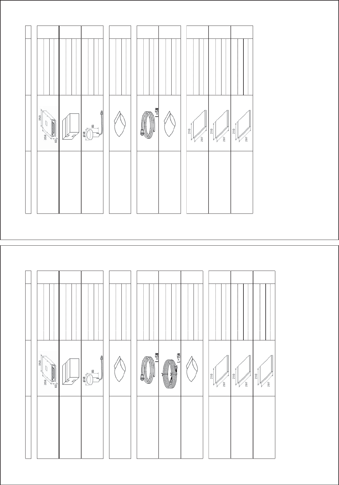
㹎㸿㹁㹉㹇㹌㹅ࠉ㹊㹇㹑㹒
(6;
)$()&&)$()&&0,-)$()&&86&*
1$0(
287/,1(
'(6&5,37,21&2'(θ
47<
ࣘࢽࢵࢺ
81,7
㺢㺵㺻㺛㺬㺽㺻㺞㺼㒊
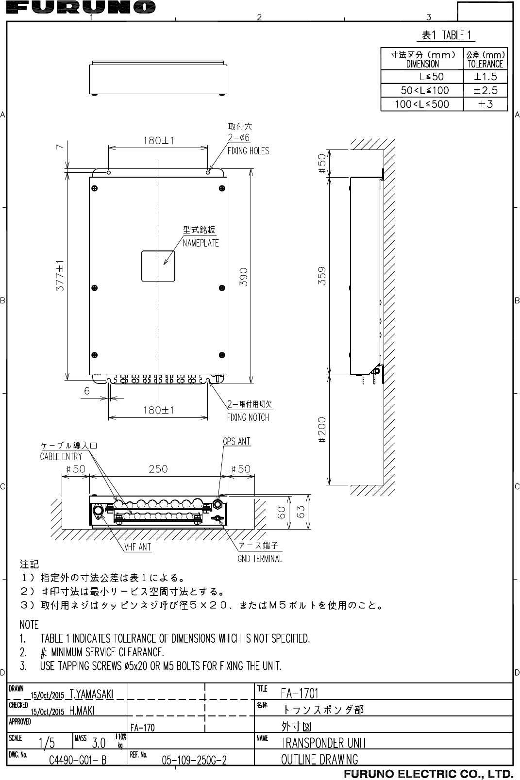
75$16321'(581,7
)$()&&
⾲♧㒊୍ᘧ⟽ワရ
021,72581,7&203/(7(6(7
)$
㺏㺻㺡㺣
$17(11$81,7
*3$6
ணഛရ
63$5(3$576
ணഛရ
63$5(3$576
63
ᕤᮦᩱ
,167$//$7,210$7(5,$/6
㺗㺎㺪㺼㺷⤌ရ
&$%/($66(0%/<
=$:*;36%/
㺗㺎㺪㺼㺷⤌ရ
&$%/($66(0%/<
71&3636'/05
ᕤᮦᩱ
,167$//$7,210$7(5,$/6
&3
ᅗ᭩
'2&80(17
ྲྀᢅㄝ᫂᭩ⱥ
23(5$72560$18$/(1
20(
᧯సせ㡿᭩ከゝㄒ
23(5$7256*8,'((1
0/*
ഛせ㡿᭩ⱥ
,167$//$7,210$18$/(1
,0(
䡶㻙䢀䢚␒ྕᮎᑿ䛾㼇㻖㻖㼉䛿䚸㑅ᢥရ䛾௦⾲䡶䡬䢀䢚䜢⾲䛧䜎䛩䚹
㻯㻻㻰㻱㻌㻺㼁㻹㻮㻱㻾㻌㻱㻺㻰㻵㻺㻳㻌㼃㻵㼀㻴㻌㻎㻖㻖㻎㻌㻵㻺㻰㻵㻯㻭㼀㻱㻿㻌㼀㻴㻱㻌㻯㻻㻰㻱㻌㻺㼁㻹㻮㻱㻾㻌㻻㻲㻌㻾㻱㻼㻾㻱㻿㻱㻺㼀㻭㼀㻵㼂㻱㻌㻹㻭㼀㻱㻾㻵㻭㻸㻚
䠄␎ᅗ䛾ᑍἲ䛿䚸ཧ⪃್䛷䛩䚹㻌㻌㻰㻵㻹㻱㻺㻿㻵㻻㻺㻿㻌㻵㻺㻌㻰㻾㻭㼃㻵㻺㻳㻌㻲㻻㻾㻌㻾㻱㻲㻱㻾㻱㻺㻯㻱㻌㻻㻺㻸㼅㻚䠅
&=%
A
-1
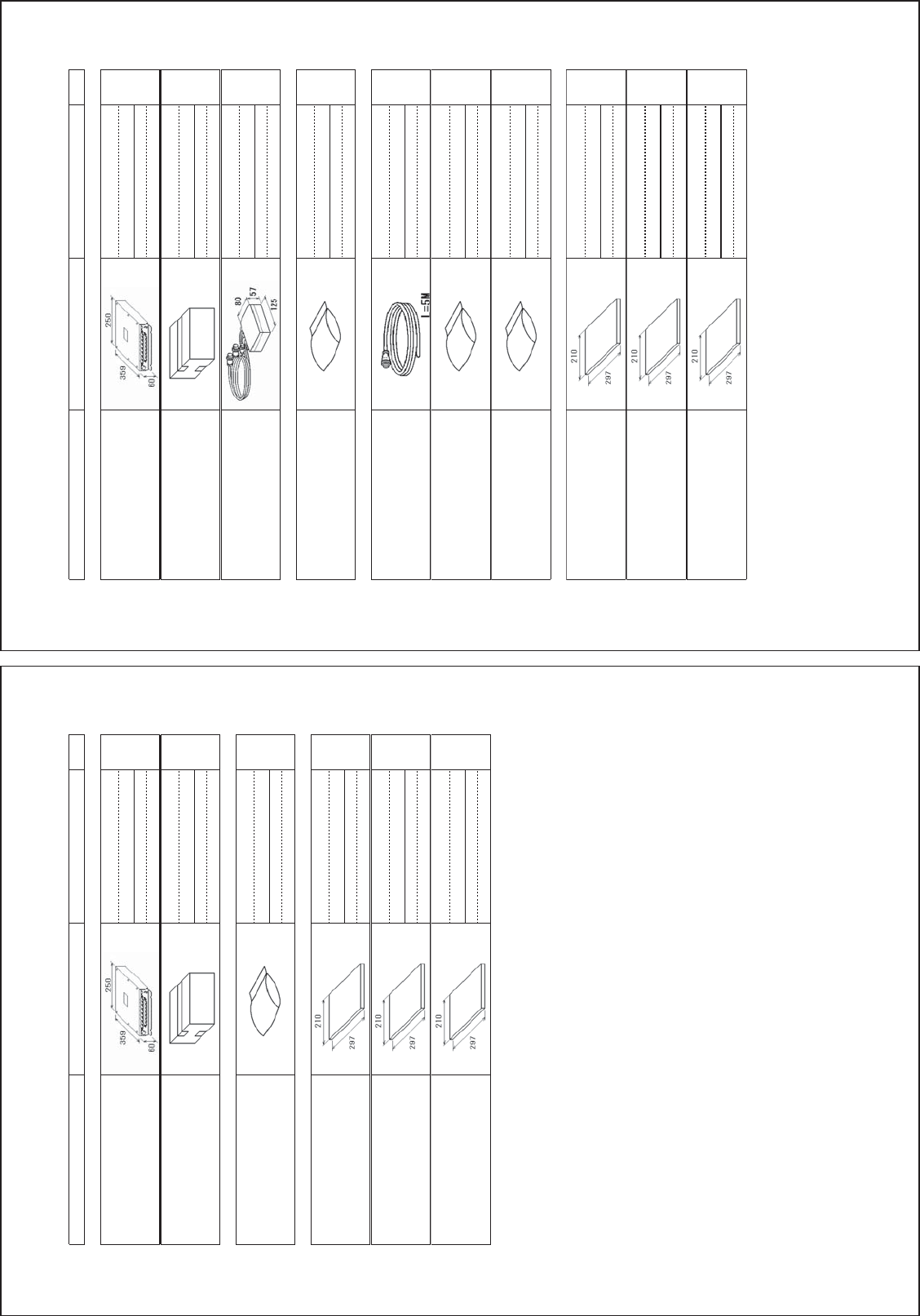
㹎㸿㹁㹉㹇㹌㹅ࠉ㹊㹇㹑㹒
(6;
)$(*3$
1$0(
287/,1(
'(6&5,37,21&2'(θ
47<
ࣘࢽࢵࢺ
81,7
㺢㺵㺻㺛㺬㺽㺻㺞㺼㒊
75$16321'(581,7
)$(
⾲♧㒊୍ᘧ⟽ワရ
021,72581,7&203/(7(6(7
)$
㺏㺻㺡㺣
$17(11$81,7
*3$6
ணഛရ
63$5(3$576
ணഛရ
63$5(3$576
63
ᕤᮦᩱ
,167$//$7,210$7(5,$/6
㺗㺎㺪㺼㺷⤌ရ
&$%/($66(0%/<
=$:*;36%/
ᕤᮦᩱ
,167$//$7,210$7(5,$/6
&3
ᅗ᭩
'2&80(17
ྲྀᢅㄝ᫂᭩ⱥ
23(5$72560$18$/(1
20(
᧯సせ㡿᭩ከゝㄒ
23(5$7256*8,'((1
0/*
ഛせ㡿᭩ⱥ
,167$//$7,210$18$/(1
,0(
䡶㻙䢀䢚␒ྕᮎᑿ䛾㼇㻖㻖㼉䛿䚸㑅ᢥရ䛾௦⾲䡶䡬䢀䢚䜢⾲䛧䜎䛩䚹
㻯㻻㻰㻱㻌㻺㼁㻹㻮㻱㻾㻌㻱㻺㻰㻵㻺㻳㻌㼃㻵㼀㻴㻌㻎㻖㻖㻎㻌㻵㻺㻰㻵㻯㻭㼀㻱㻿㻌㼀㻴㻱㻌㻯㻻㻰㻱㻌㻺㼁㻹㻮㻱㻾㻌㻻㻲㻌㻾㻱㻼㻾㻱㻿㻱㻺㼀㻭㼀㻵㼂㻱㻌㻹㻭㼀㻱㻾㻵㻭㻸㻚
䠄␎ᅗ䛾ᑍἲ䛿䚸ཧ⪃್䛷䛩䚹㻌㻌㻰㻵㻹㻱㻺㻿㻵㻻㻺㻿㻌㻵㻺㻌㻰㻾㻭㼃㻵㻺㻳㻌㻲㻻㻾㻌㻾㻱㻲㻱㻾㻱㻺㻯㻱㻌㻻㻺㻸㼅㻚䠅
&=%
A
-2
㹎㸿㹁㹉㹇㹌㹅ࠉ㹊㹇㹑㹒
(6;
)$(9)$(+.9
1$0(
287/,1(
'(6&5,37,21&2'(θ
47<
ࣘࢽࢵࢺ
81,7
㺢㺵㺻㺛㺬㺽㺻㺞㺼㒊
75$16321'(581,7
)$
⾲♧㒊୍ᘧ⟽ワရ
021,72581,7&203/(7(6(7
)$
ᕤᮦᩱ
,167$//$7,210$7(5,$/6
ᕤᮦᩱ
,167$//$7,210$7(5,$/6
&3
ᅗ᭩
'2&80(17
ྲྀᢅㄝ᫂᭩ⱥ
23(5$72560$18$/(1
20(
᧯సせ㡿᭩ከゝㄒ
23(5$7256*8,'((1
0/*
ഛせ㡿᭩ⱥ
,167$//$7,210$18$/(1
,0(
䡶㻙䢀䢚␒ྕᮎᑿ䛾㼇㻖㻖㼉䛿䚸㑅ᢥရ䛾௦⾲䡶䡬䢀䢚䜢⾲䛧䜎䛩䚹
㻯㻻㻰㻱㻌㻺㼁㻹㻮㻱㻾㻌㻱㻺㻰㻵㻺㻳㻌㼃㻵㼀㻴㻌㻎㻖㻖㻎㻌㻵㻺㻰㻵㻯㻭㼀㻱㻿㻌㼀㻴㻱㻌㻯㻻㻰㻱㻌㻺㼁㻹㻮㻱㻾㻌㻻㻲㻌㻾㻱㻼㻾㻱㻿㻱㻺㼀㻭㼀㻵㼂㻱㻌㻹㻭㼀㻱㻾㻵㻭㻸㻚
䠄␎ᅗ䛾ᑍἲ䛿䚸ཧ⪃್䛷䛩䚹㻌㻌㻰㻵㻹㻱㻺㻿㻵㻻㻺㻿㻌㻵㻺㻌㻰㻾㻭㼃㻵㻺㻳㻌㻲㻻㻾㻌㻾㻱㻲㻱㻾㻱㻺㻯㻱㻌㻻㻺㻸㼅㻚䠅
&=$
A
-3
㹎㸿㹁㹉㹇㹌㹅ࠉ㹊㹇㹑㹒
(6;
)$('%
1$0(
287/,1(
'(6&5,37,21&2'(θ
47<
ࣘࢽࢵࢺ
81,7
㺢㺵㺻㺛㺬㺽㺻㺞㺼㒊
75$16321'(581,7
)$(
⾲♧㒊୍ᘧ⟽ワရ
021,72581,7&203/(7(6(7
)$
ศ㓄ჾ
',675,%87(581,7
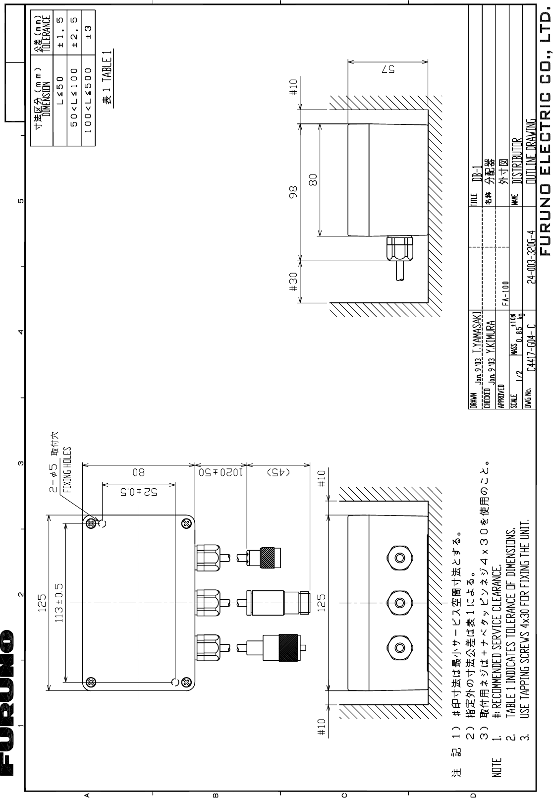
'%
ணഛရ
63$5(3$576
ணഛရ
63$5(3$576
63
ᕤᮦᩱ
,167$//$7,210$7(5,$/6
㺗㺎㺪㺼㺷⤌ရ
&$%/($66(0%/<
=$:*;36%/
ᕤᮦᩱ
,167$//$7,210$7(5,$/6
&3
ᕤᮦᩱ
,167$//$7,210$7(5,$/6
&3
ᅗ᭩
'2&80(17
ྲྀᢅㄝ᫂᭩ⱥ
23(5$72560$18$/(1
20(
᧯సせ㡿᭩ከゝㄒ
23(5$7256*8,'((1
0/*
ഛせ㡿᭩ⱥ
,167$//$7,210$18$/(1
,0(
䡶㻙䢀䢚␒ྕᮎᑿ䛾㼇㻖㻖㼉䛿䚸㑅ᢥရ䛾௦⾲䡶䡬䢀䢚䜢⾲䛧䜎䛩䚹
㻯㻻㻰㻱㻌㻺㼁㻹㻮㻱㻾㻌㻱㻺㻰㻵㻺㻳㻌㼃㻵㼀㻴㻌㻎㻖㻖㻎㻌㻵㻺㻰㻵㻯㻭㼀㻱㻿㻌㼀㻴㻱㻌㻯㻻㻰㻱㻌㻺㼁㻹㻮㻱㻾㻌㻻㻲㻌㻾㻱㻼㻾㻱㻿㻱㻺㼀㻭㼀㻵㼂㻱㻌㻹㻭㼀㻱㻾㻵㻭㻸㻚
䠄␎ᅗ䛾ᑍἲ䛿䚸ཧ⪃್䛷䛩䚹㻌㻌㻰㻵㻹㻱㻺㻿㻵㻻㻺㻿㻌㻵㻺㻌㻰㻾㻭㼃㻵㻺㻳㻌㻲㻻㻾㻌㻾㻱㻲㻱㻾㻱㻺㻯㻱㻌㻻㻺㻸㼅㻚䠅
&=%
A
-4
㹎㸿㹁㹉㹇㹌㹅ࠉ㹊㹇㹑㹒
(6;
)$-(
1$0(
287/,1(
'(6&5,37,21&2'(θ
47<
ࣘࢽࢵࢺ
81,7
㺢㺵㺻㺛㺬㺽㺻㺞㺼㒊
75$16321'(581,7
)$
䡶㻙䢀䢚␒ྕᮎᑿ䛾㼇㻖㻖㼉䛿䚸㑅ᢥရ䛾௦⾲䡶䡬䢀䢚䜢⾲䛧䜎䛩䚹
㻯㻻㻰㻱㻌㻺㼁㻹㻮㻱㻾㻌㻱㻺㻰㻵㻺㻳㻌㼃㻵㼀㻴㻌㻎㻖㻖㻎㻌㻵㻺㻰㻵㻯㻭㼀㻱㻿㻌㼀㻴㻱㻌㻯㻻㻰㻱㻌㻺㼁㻹㻮㻱㻾㻌㻻㻲㻌㻾㻱㻼㻾㻱㻿㻱㻺㼀㻭㼀㻵㼂㻱㻌㻹㻭㼀㻱㻾㻵㻭㻸㻚
䠄␎ᅗ䛾ᑍἲ䛿䚸ཧ⪃್䛷䛩䚹㻌㻌㻰㻵㻹㻱㻺㻿㻵㻻㻺㻿㻌㻵㻺㻌㻰㻾㻭㼃㻵㻺㻳㻌㻲㻻㻾㻌㻾㻱㻲㻱㻾㻱㻺㻯㻱㻌㻻㻺㻸㼅㻚䠅
&=$
A
-5
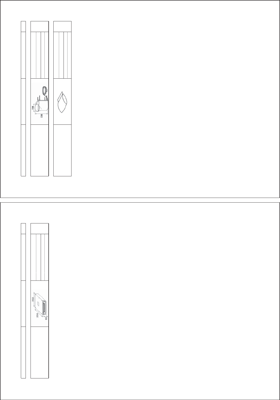
㹎㸿㹁㹉㹇㹌㹅ࠉ㹊㹇㹑㹒
(6;
*9$7*9$7+.
1$0(
287/,1(
'(6&5,37,21&2'(θ
47<
ࣘࢽࢵࢺ
81,7
」ྜ✵୰⥺㒊
*369+)&20%,1('$17(11$
*9$7+.
ᕤᮦᩱ
,167$//$7,210$7(5,$/6
ᕤᮦᩱ
,167$//$7,210$7(5,$/6
&3
䡶㻙䢀䢚␒ྕᮎᑿ䛾㼇㻖㻖㼉䛿䚸㑅ᢥရ䛾௦⾲䡶䡬䢀䢚䜢⾲䛧䜎䛩䚹
㻯㻻㻰㻱㻌㻺㼁㻹㻮㻱㻾㻌㻱㻺㻰㻵㻺㻳㻌㼃㻵㼀㻴㻌㻎㻖㻖㻎㻌㻵㻺㻰㻵㻯㻭㼀㻱㻿㻌㼀㻴㻱㻌㻯㻻㻰㻱㻌㻺㼁㻹㻮㻱㻾㻌㻻㻲㻌㻾㻱㻼㻾㻱㻿㻱㻺㼀㻭㼀㻵㼂㻱㻌㻹㻭㼀㻱㻾㻵㻭㻸㻚
䠄␎ᅗ䛾ᑍἲ䛿䚸ཧ⪃್䛷䛩䚹㻌㻌㻰㻵㻹㻱㻺㻿㻵㻻㻺㻿㻌㻵㻺㻌㻰㻾㻭㼃㻵㻺㻳㻌㻲㻻㻾㻌㻾㻱㻲㻱㻾㻱㻺㻯㻱㻌㻻㻺㻸㼅㻚䠅
C4490-Z14-A
A
-6
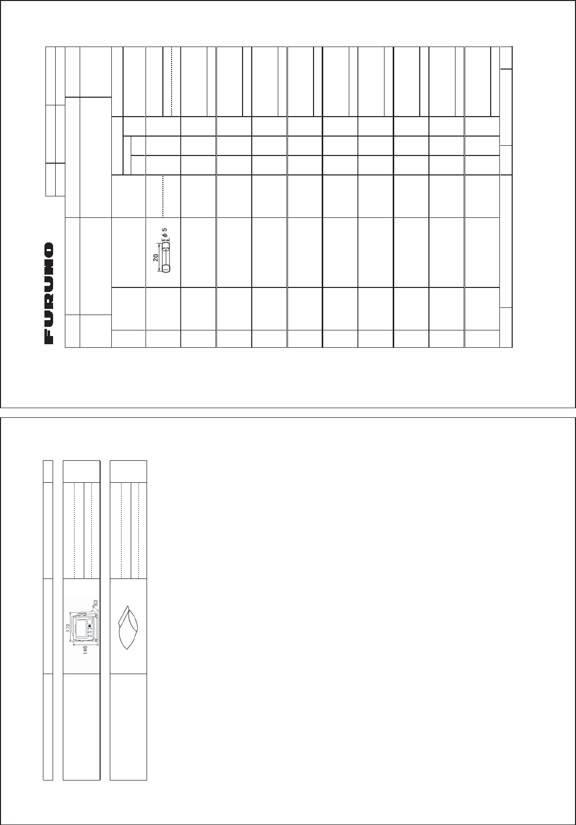
㹎㸿㹁㹉㹇㹌㹅ࠉ㹊㹇㹑㹒
(6;
)$+.
1$0(
287/,1(
'(6&5,37,21&2'(θ
47<
ࣘࢽࢵࢺ
81,7
⾲♧㒊
021,72581,7
)$
ᕤᮦᩱ
,167$//$7,210$7(5,$/6
ᕤᮦᩱ
,167$//$7,210$7(5,$/6
&3
䡶㻙䢀䢚␒ྕᮎᑿ䛾㼇㻖㻖㼉䛿䚸㑅ᢥရ䛾௦⾲䡶䡬䢀䢚䜢⾲䛧䜎䛩䚹
㻯㻻㻰㻱㻌㻺㼁㻹㻮㻱㻾㻌㻱㻺㻰㻵㻺㻳㻌㼃㻵㼀㻴㻌㻎㻖㻖㻎㻌㻵㻺㻰㻵㻯㻭㼀㻱㻿㻌㼀㻴㻱㻌㻯㻻㻰㻱㻌㻺㼁㻹㻮㻱㻾㻌㻻㻲㻌㻾㻱㻼㻾㻱㻿㻱㻺㼀㻭㼀㻵㼂㻱㻌㻹㻭㼀㻱㻾㻵㻭㻸㻚
䠄␎ᅗ䛾ᑍἲ䛿䚸ཧ⪃್䛷䛩䚹㻌㻌㻰㻵㻹㻱㻺㻿㻵㻻㻺㻿㻌㻵㻺㻌㻰㻾㻭㼃㻵㻺㻳㻌㻲㻻㻾㻌㻾㻱㻲㻱㻾㻱㻺㻯㻱㻌㻻㻺㻸㼅㻚䠅
&=$
A
-7
&2'(12
7<3(
63
,7(0
12
1$0(2)
3
3$57
287/,1(
':*12
25
3(5
6
6(7
3(5
9
9(6
63$5(
:25.,1*
48$17,7<
5(0$5.6&2'(12
%2;123
6+,312
63$5(3$576/,67)25
86(
6(763(5
9
9(66(/
7<3(12
(6;
㺩㺋㺎㺛㺼
)*0%9$
3%)
*/$6678%(
)86(
0)561$0(
)85812(/(&75,&&2/7'
':*12
㸦␎ᅗࡢᑍἲࡣࠊཧ⪃್࡛ࡍࠋࠉ',0(16,216,1'5$:,1*ࠉ)255()(5(1&(21/<㸧
&3$
A
-8
D-1
Feb.22'05
D-2
Feb.22'05
D-3
Jan. 9, '03
Mar.27'07 R.Esumi
D-4
D-5
16/Apr/2015 H.MAKI
D-6
16/Apr/2015 H.MAKI
D-7
16/Apr/2015 H.MAKI
D-8
16/Apr/2015 H.MAKI
D-9
16/Apr/2015 H.MAKI
12 456
3
B
A
D
C
NAME
名称
TITLE
kg
MASS
DWG No.
SCALE
APPROVED
CHECKED
DRAWN
REF.No.
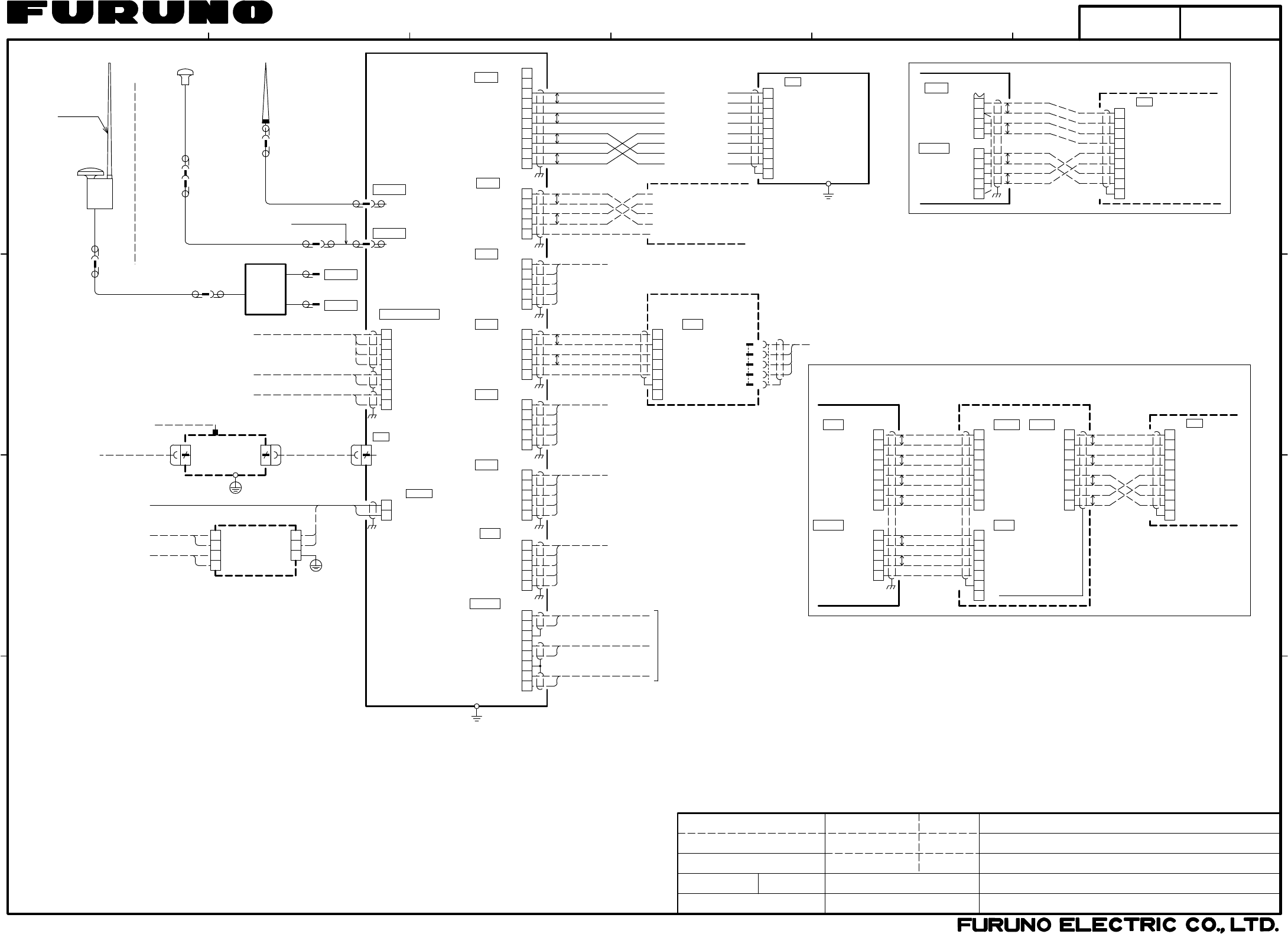
INTERCONNECTION DIAGRAM
相互結線図
FA-170
国際船舶自動識別装置
P
P12V_P
GND
3
4
5
6
PON-H
PON-C P
P
5
4
3
2
1
GND_ISO
COM1-6
P
TB3-8
TB2
DISP
FA-1701
8
7
6
5
4
3
PON-H
PON-C
DISP_TD-A
DISP_TD-B
DISP_RD-A
DISP_RD-B
GND
P12V_P
9
10
5
4
3
2
1
COM_RD-A
COM_RD-B
COM_TD-B
COM_TD-A
RD-B
RD-A
TD-B
TD-A
PON-C
PON-H
P12V_P
GND
8
7
6
5
4
3
2
1
AIS_TD-A
AIS_TD-B
AIS_RD-A
AIS_RD-B
FG
FG
1
2
3
4
5
6
7
GND_ISO
FA-1701 FA-1703
TB2 DISP1
TB1 COM
RD-B
RD-A
TD-B
TD-A
PON-C
PON-H
P12V_P
GND
9
8
7
6
5
4
3
2
1
FG
COM
J301 表示部
FA-1702
MONITOR
UNIT
RD-B
RD-A
TD-B
TD-A
PON-C
PON-H
P12V_P
GND
1
2
3
4
5
6
7
8
TB3DISP2
P
P
P
P
P
P
P
P
P
P
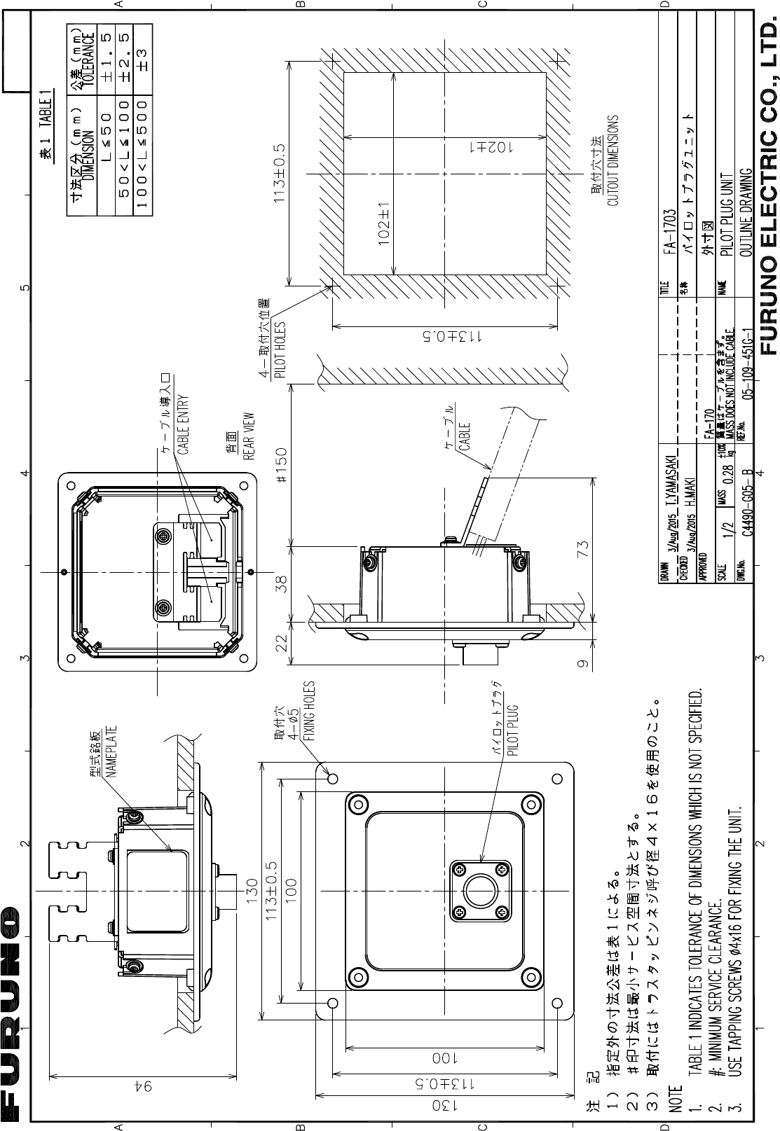
パイロットプラグユニットを経由したトランスポンダ部-表示部の結線
CONNECTION BETWEEN TRANSPONDER UNIT AND MONITOR UNIT VIA PILOT PLUG UNIT
MAX.100m
TTYCSLA-7
MAX.5m
TTYCSLA-4
*1 *1
RD-B
RD-A
TD-B
TD-A
PON-C
PON-H
P12V_P
GND
9
8
7
6
5
4
3
2
1
FG
COM
J301
MONITOR UNIT
表示部
FA-1702
TTYCSLA-4,MAX.100m
TB2
TB3-8
DISP
COM1-6
GND_ISO
NOTE
*1: SHIPYARD SUPPLY.
*2: OPTION.
注記
*1)造船所手配。
*2)オプション。
T.YAMASAKI
1m
1m
N-P-8DFB
N-J-3
0.8m
N-J-3
N-P-8DFB
M-P-7
N-P-8DFB TNC-J-3
TNCP-NJ
0.2m
NJ-TP-3DXV,1m
N-P-8DFB
M-P-7
1m
8
7
6
5
4
3
2
1
SILENT-C
SILENT-H
BLUESIGN-C
BLUESIGN-H
ALM_ACK-H
EXT_ALM-C
EXT_ALM-H
ALM_ACK-C
*1
TTYCSLA-1,MAX.100m
*1
TTYCSLA-1,MAX.100m
*1
BLUESIGN
DB-1
分配器
DISTRI-
BUTOR
RG-10/UY
*1
8D-FB-CV,30/40/50m *2
RG-10/UY,MAX.20m *1
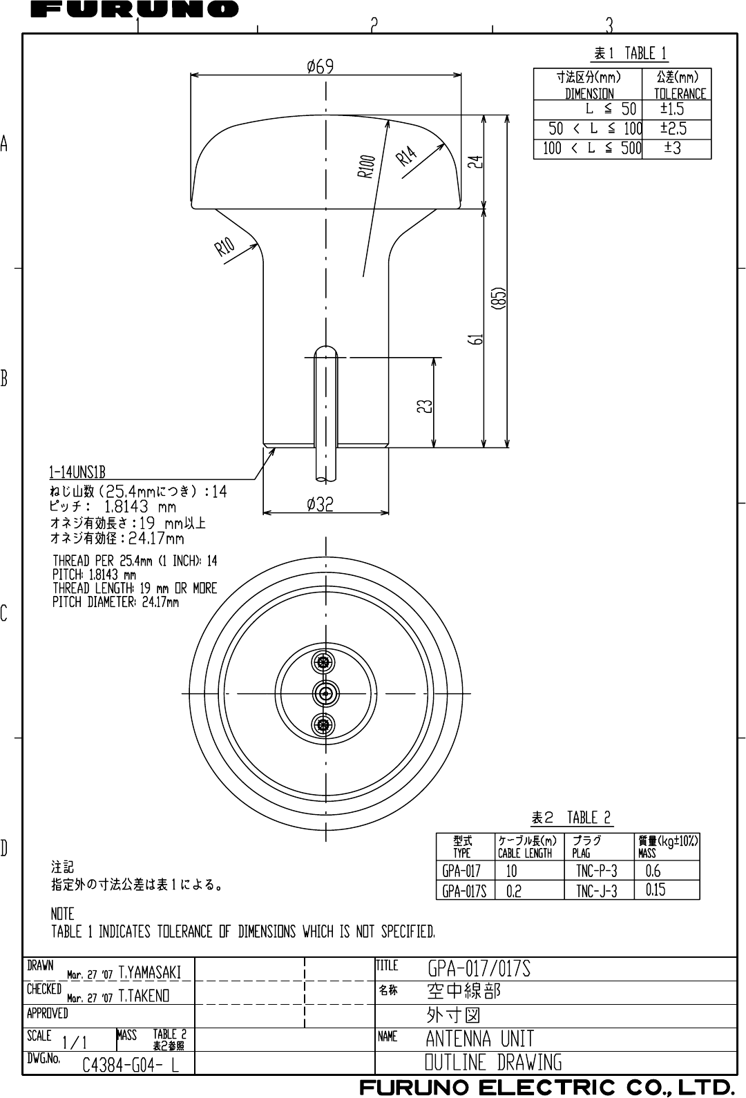
GPA-017S
GPSアンテナ
GPS ANTENNA
8D-FB-CV,30/40/50m *2
RG-10/UY,MAX.20m *1
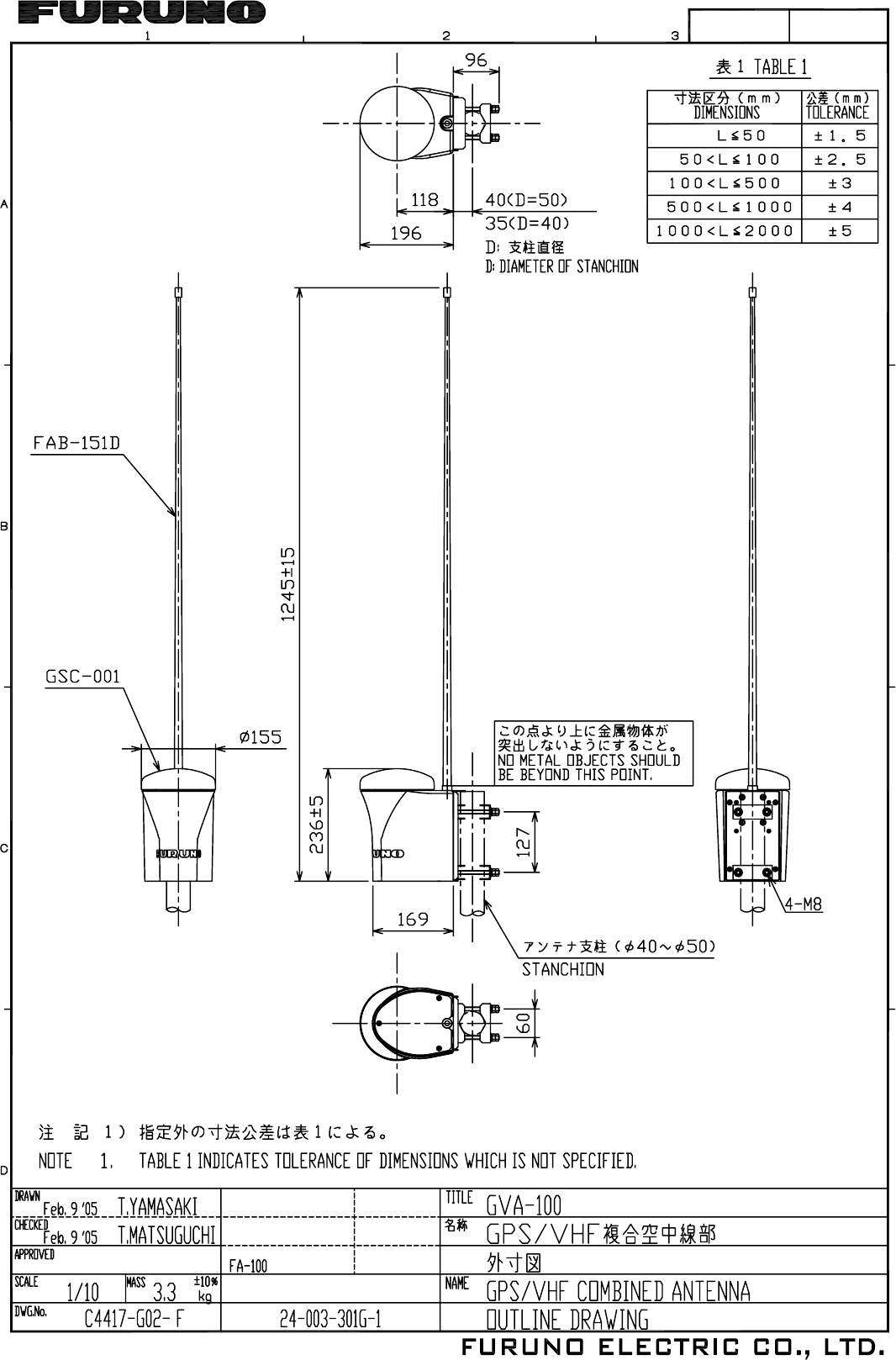
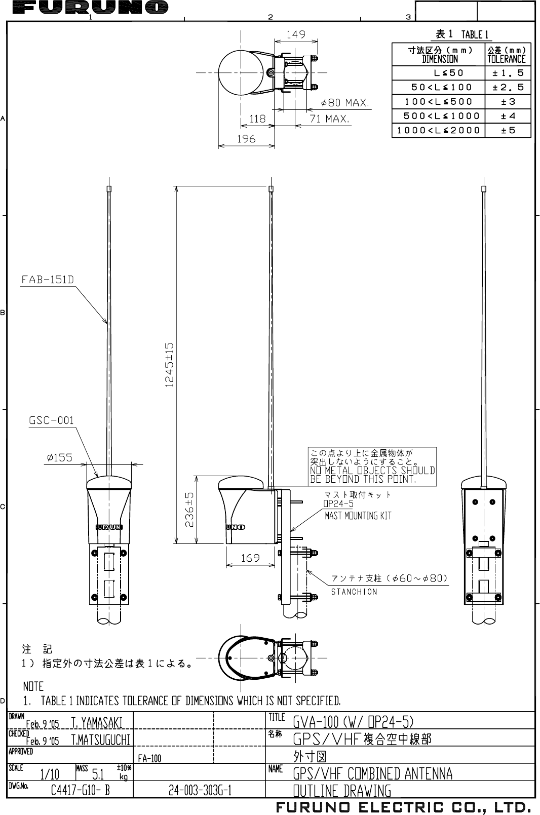
FAB-151D
TNC-P-3
M-P-3
8
J7
RJ45 LAN
選択
SELECT
TB10
トランスポンダ部
TRANSPONDER UNIT
FA-1701
ALARM SYSTEM
SILENT SWITCH
サイレントスイッチ
アラームシステム
-
+
-
+
E
PE 保護アース
IV-2sq. *1
AC/DC電源ユニット
*2
PR-240
AC/DC POWER
SUPPLY UNIT
*1
DPYC-2.5
24VDC
DPYC-1.5
*1
200-230VAC
100-115/
1φ,50/60Hz
12-24VDC 2
1
DC_IN(-)
DC_IN(+)
TB1 POWER
5
4
3
2
1
TB5
8
7
6
5
4
3
2
1
TB2
PON-H
PON-C
DISP_TD-A
DISP_TD-B
DISP_RD-A
DISP_RD-B
GND
P12V_P
9
10
NC
NC
5
4
3
2
1
COM2_TD-A
COM2_TD-B
COM2_RD-A
COM2_RD-B
COM2_GND_ISO
5
4
3
2
1
COM1_TD-A
COM1_TD-B
COM1_RD-A
COM1_RD-B
COM1_GND_ISO
P
P
TB4
TB3
P
P
P
P
同上
DITTO
COM3_TD-A
COM3_TD-B
COM3_RD-A
COM3_RD-B
5
4
3
2
1
COM4_TD-A
COM4_TD-B
COM4_RD-A
COM4_RD-B
同上
DITTO
5
4
3
2
1同上
DITTO
P
P
COM5_TD-A
COM5_TD-B
COM5_RD-A
COM5_RD-B
5
4
3
2
1同上
DITTO
TB6
TB7
TB8
COM6_TD-A
COM6_TD-B
COM6_RD-A
COM6_RD-B
8
7
6
5
4
3
2
1
SENS1-H
SENS1-C
SENS2-C
SENS2-H
SG
SG
SENS3-H
SENS3-C
TB9
*1
TTYCSLA-1,MAX.100m
*1
TTYCSLA-1,MAX.100m
*1
TTYCSLA-1,MAX.100m
IV-2sq.
*1
AIS_TD-A
AIS_TD-B
AIS_RD-A
AIS_RD-B
FG
FG
1
2
3
4
5
6
7
GND_ISO
TB1 COM
TTYCSLA-4,MAX.100m
*1
GND
RD-A
TD-A
TD-B
RD-B
TTYCSLA-4,MAX.100m
*1
SENSOR
(IEC61162-1)
ROT
SPEED LOG
GYROCOMPASS
SENSOR: GPS
DISP
COM6
SENSOR
COM3
COM2
COM1
COM4
COM5
GPS ANT
VHF ANT
VHF ANT
GPS ANT
PC
206486-1
9
6
5
4
1
*3
パイロットプラグユニット
PILOT PLUG UNIT FA-1703
*2
COM3_GND_ISO
COM4_GND_ISO
COM5_GND_ISO
COM6_GND_ISO
TX-A
TX-B
RX-A
RX-B
SHIELD
206485-1
ALM/BS/SILENT
TTYCSLA-1Q,MAX.100m
*2
H.MAKI
*1
TTYCSLA-4,MAX.100m
または
OR
8
NR203PF-VVS1.25
3
HUB-100
SWITCHING HUB
スイッチングハブ
*1
STP(CAT5)
RADAR/ECDIS
レーダー/ECDIS
1φ,50/60Hz
100-230VAC
DPYC-2.5
*1
IV-2sq.
*1
RJ45
OR STP(CAT5)
MAX.100m,φ13
FR-FTPC-CY,
*1
3.5m,φ8.6
*2
VHFアンテナ
VHF ANTENNA
複合空中線部
GPS/VHF ANTENNA
*3)TYCO ELECTRONICS社(旧AMP社)製。
*3: PRODUCED BY TYCO ELECTRONICS (AMP) INC.
*4)国際向専用ケーブル。カラーコードは専用ケーブルのもの。
TD-A
TD-B
RD-A
RD-B
FAB-151D
*2
PNK/RED
PNK/BLK
YEL/BLK
GRY/BLK
WHT/BLK
YEL/RED
GRY/RED
WHT/RED
モモ/アカ
モモ/クロ
キ/アカ
キ/クロ
ハイ/アカ
ハイ/クロ
シロ/アカ
シロ/クロ
*4
Z-AWG25X4P-SB,
5m(10m),φ8.9
MONITOR UNIT
表示部
FA-1702
RD-B
RD-A
TD-B
TD-A
PON-C
PON-H
P12V_P
GND
9
8
7
6
5
4
3
2
1
FG
COM
J301
IV-1.25sq.
*1
U-AIS TRANSPONDER
*4: 5m:STANDARD SUPPLY. 10m:OPTION. COLOR CODES SHOW CORES OF THE SUPPLIED CABLE.
(IEC61162-1/2)
ビーコン
RADAR/ECDIS/BEACON
05-109-1001-0
GSC-001
GPA-020S
レーダー/ECDIS/
第2表示部 No.2 MONITOR UNIT
9/Oct/2015
9/Oct/2015
C4490-C01- B
S-1
13/Oct/2015 H.MAKI