Furuno USA 9ZWFA170 Automatic Identification Systems User Manual OME 44900 A
Furuno USA Inc Automatic Identification Systems OME 44900 A
Contents
User Manual

FA-170
OPERATOR'S MANUAL
www.furuno.com
Model
CLASS A AIS
PRODUCT NAME: U-AIS TRANSPONDER
Z10
(GREG) FA-170
OME-44900-Z10
OCT. 30, 2015:

i
IMPORTANT NOTICES
General
• The operator of this equipment must read and follow the descriptions in this manual. Wrong op-
eration or maintenance can cancel the warranty or cause injury.
• Do not copy any part of this manual without written permission from FURUNO.
• If this manual is lost or worn, contact your dealer about replacement.
• The contents of this manual and equipment specifications can change without notice.
• The example screens (or illustrations) shown in this manual can be different from the screens
you see on your display. The screens you see depend on your system configuration and equip-
ment settings.
• Save this manual for future reference.
• Any modification of the equipment (including software) by persons not authorized by FURUNO
will cancel the warranty.
• All brand and product names are trademarks, registered trademarks or service marks of their
respective holders.
How to discard this product
Discard this product according to local regulations for the disposal of industrial waste. For disposal
in the USA, see the homepage of the Electronics Industries Alliance (http://www.eiae.org/) for the
correct method of disposal.
How to discard a used battery
Some FURUNO products have a battery(ies). To see if your product has a battery, see the chapter
on Maintenance. Follow the instructions below if a battery is used. Tape the + and - terminals of
battery before disposal to prevent fire, heat generation caused by short circuit.
In the European Union
The crossed-out trash can symbol indicates that all types of batteries
must not be discarded in standard trash, or at a trash site. Take the
used batteries to a battery collection site according to your national
legislation and the Batteries Directive 2006/66/EU.
In the USA
The Mobius loop symbol (three chasing arrows) indicates that Ni-Cd
and lead-acid rechargeable batteries must be recycled. Take the used
batteries to a battery collection site according to local laws.
In the other countries
There are no international standards for the battery recycle symbol. The number of symbols can
increase when the other countries make their own recycle symbols in the future.
Cd
Ni-Cd Pb
ii
SAFETY INSTRUCTIONS
The operator must read the safety instructions before attempting to operate this equipment
WARNING
Immediately turn off the power at the
switchboard if water leaks into the
equipment or something is dropped
in the equipment.
Continued use of the equipment can
cause fire or electrical shock. Contact a
FURUNO agent for service.
Do not disassemble or modify the
equipment.
Fire, electrical shock or serious injury
can result.
Do not place liquid-filled containers
on the top of the equipment.
Fire or electrical shock can result if a
liquid spills into the equipment.
Use the proper fuse.
Use of the wrong fuse can cause fire or
permanent damage to the equipment.
ELECTRICAL SHOCK HAZARD
Do not open the equipment.
Only qualified personnel should work
inside the equipment.
WARNING
To avoid electrical shock, do not
remove cover. No user-serviceable
parts inside.
Unit: PR-240 Power Supply
Name: Warning Label (1)
Type: 86-003-1011-3
CodeNo.: 100-263-233-10
WARNING LABEL
A warning label is attached to the AC-DC power
supply. Do not remove the label.
If the label is missing or damaged, contact a
FURUNO agent or dealer about replacement.
Mandatory Action
Prohibitive Action
WARNING
CAUTION
Warning, Caution
Indicates a potentially hazardous situation which, if not avoided,
could result in death or serious injury.
Indicates a potentially hazardous situation which, if not avoided,
can result in minor or moderate injury.
WARNING
Immediately turn off the power at the
switchboard if the equipment is
emitting smoke or fire.
Continued use of the equipment can
cause fire or electrical shock. Contact a
FURUNO agent for service.
Make sure no rain or water splash
leaks into the equipment.
Fire or electrical shock can result if water
leaks in the equipment.
Do not operate the equipment with
wet hands.
Electrical shock can result.
The glass of an LCD panel breaks
easily. Handle the LCD carefully.
Injury can result if the glass breaks.
About the TFT LCD
The TFT LCD is constructed using the latest LCD
techniques, and displays 99.99% of its pixels. The
remaining 0.01% of the pixels may drop out or blink,
however this is not an indication of malfunction.
Do not approach the antenna closer
than listed below when it is
transmitting.
The antenna emits radio waves that
can be harmful to the human body.
RF power density on antenna aperture Distance
100 W/m2
10 W/m2
2 W/m20.09 m
0.04 m
N/A
iii
SYSTEM OVERVIEW
System overview
The Automatic Identification System (AIS) was originally developed to aid the Vessel Traffic Ser-
vices (VTS) by use of a VHF transponder working on Digital Selective Call (DSC) at VHF CH70,
and is still in use along the UK coastal areas and others. Some time later the IMO developed a
Universal AIS using the new sophisticated technology called Self-Organized Time Division Multi-
ple Access (SOTDMA) based on a VHF Data Link (VDL).
The system operates in three modes – autonomous (continuous operation in all areas), assigned
(data transmission interval remotely controlled by authority in traffic monitoring service) and polled
(in response to interrogation from a ship or authority). It is synchronized with GPS time to avoid
conflict among multiple users (IMO minimum 2000 reports per minute and IEC requires 4500 re-
ports on two channels). The VHF channels 87B and 88B are commonly used and in addition there
are local AIS frequencies. Shipborne AIS transponders exchange various data as specified by the
IMO and ITU on either frequency automatically set up by the frequency management telecom-
mand received by the DSC receiver on ship.
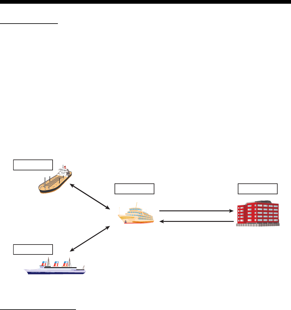
AIS system
Not all ships carry AIS
The Officer of the Watch (OOW) should always be aware that other ships, and in particular leisure
craft, fishing boats and warships, and some coastal shore stations (including Vessel Traffic Ser-
vice centers) might not be fitted with AIS.
The OOW should also be aware that AIS fitted on other ships as a mandatory carriage require-
ment might be switched off by the master if its use might compromise the security of the vessel.
Thus, users are therefore cautioned to always bear in mind that information provided by AIS may
not be giving a complete or correct “picture” of shipping traffic in their vicinity.
VTS Center
Own ship transmits
static/dynamic data*
Transmits and receives
static/dynamic data*
Transmits and receives
static/dynamic data*
*: Static data - MMSI, Name, etc.
Dynamic data - Position, bearing, COG, etc.
VTS Center sends various
information including
weather conditions and
frequency assignments.
Own ship
Other ship1
Other ship2

SYSTEM OVERVIEW
iv
Use of AIS in collision avoidance
As an anti-collision aid, the AIS has the following advantages over radar:
• Information provided in near real-time
• Capable of instant presentation of target course alterations
• Not subject to target swap
• Not subject to target loss in clutter
• Not subject to target loss due to abrupt maneuvers
• Able to “detect” ships within VHF/FM coverage, including in some circumstances, around bends
and behind islands.
When using the AIS for anti-collision purposes it is important to remember that the AIS is an ad-
ditional source of navigation information. It does not replace other navigational systems. The AIS
may not be giving a complete or correct “picture” of shipping traffic in its vicinity.
The use of the AIS does not negate the responsibility of the OOW to comply with all collision reg-
ulation requirements, especially the maintaining of a proper look-out. The prudent navigator uses
all aids available to navigate the ship.
Erroneous information
Erroneous information implies a risk to other ships as well as your own. Poorly configured or im-
properly calibrated sensors might lead to incorrect information being transmitted. It is the user’s
responsibility to ensure that all information entered into the system is correct and up to date.

v
TABLE OF CONTENTS
FOREWORD.................................................................................................................. vii
SYSTEM CONFIGURATION .......................................................................................... ix
1. OPERATION ..........................................................................................................1-1
1.1 Description of Controls ...............................................................................................1-1
1.2 How to Turn the Power On and Off ............................................................................1-2
1.3 How to Adjust the Panel and Display Brilliance..........................................................1-3
1.4 Display Overview........................................................................................................1-4
1.5 Menu Overview...........................................................................................................1-5
1.5.1 Menu operating procedure .............................................................................1-5
1.5.2 How to select a menu option ..........................................................................1-6
1.5.3 How to enter numeric data .............................................................................1-6
1.5.4 How to use the software keyboard for alphanumeric input ............................1-6
1.6 How to Enter Voyage-Related Data ...........................................................................1-7
1.7 How to Set the Notification .......................................................................................1-10
1.8 How to Select a Display............................................................................................1-11
1.8.1 Plotter display...............................................................................................1-12
1.8.2 Target list......................................................................................................1-14
1.8.3 Dangerous (target) list..................................................................................1-15
1.8.4 How to interpret the [TARGET DETAIL] screen ...........................................1-16
1.8.5 Own ship data ..............................................................................................1-18
1.8.6 Alert display..................................................................................................1-19
1.9 Messages .................................................................................................................1-20
1.9.1 How to send a message...............................................................................1-20
1.9.2 Receiving messages ....................................................................................1-22
1.9.3 How to use the message box (MSG BOX) ...................................................1-22
1.10 Regional Operating Channels ..................................................................................1-24
1.10.1 How to view channel information..................................................................1-24
1.10.2 How to edit/view regional channels ..............................................................1-25
1.11 How to Enable/Disable the Key Beep.......................................................................1-28
1.12 Long Range..............................................................................................................1-28
1.12.1 How to set up long range response..............................................................1-28
1.12.2 How to broadcast own ship data ..................................................................1-29
1.13 Pilot Plug (FA-1703, option) .....................................................................................1-30
1.14 Viewing Initial Settings..............................................................................................1-31
1.15 Setting for Time Difference.......................................................................................1-32
2. INLAND AIS OPERATION ....................................................................................2-1
2.1 How to Activate the Inland AIS ...................................................................................2-1
2.2 Selecting AIS Mode....................................................................................................2-2
2.3 How to Enter Voyage-Related Data ...........................................................................2-3
2.4 Static Data..................................................................................................................2-8
2.5 Target List and Dangerous Target List .......................................................................2-9
2.5.1 Target list........................................................................................................2-9
2.5.2 Dangerous (target) list..................................................................................2-11
2.5.3 How to interpret the [TARGET DETAIL] screen ...........................................2-11
2.6 Inland AIS Specific Messaging.................................................................................2-14
2.6.1 How to send a text message ........................................................................2-14
2.6.2 How to view a sent text message.................................................................2-16
2.6.3 ETA and RTA messages..............................................................................2-16
2.6.4 No. of persons message ..............................................................................2-20
2.6.5 EMMA warning message .............................................................................2-21
TABLE OF CONTENTS
vi
2.6.6 Water level message.................................................................................... 2-22
2.7 Viewing Initial Settings ............................................................................................. 2-23
2.8 Setting for Time Difference ...................................................................................... 2-24
3. MAINTENANCE, TROUBLESHOOTING...............................................................3-1
3.1 Maintenance............................................................................................................... 3-1
3.2 Replacement of Fuse ................................................................................................. 3-2
3.3 Troubleshooting ......................................................................................................... 3-2
3.4 Diagnostics................................................................................................................. 3-3
3.4.1 Monitor unit test.............................................................................................. 3-3
3.4.2 Transponder test............................................................................................ 3-4
3.4.3 VHF communication test................................................................................ 3-5
3.4.4 TX on/off log................................................................................................... 3-6
3.5 Alerts .......................................................................................................................... 3-7
3.6 GPS Monitor............................................................................................................... 3-8
3.7 Displaying Sensor Status........................................................................................... 3-9
3.8 How to Restore Default Settings.............................................................................. 3-10
3.9 AIS-SART Test Indication in Target List .................................................................. 3-10
APPENDIX 1 MENU TREE .......................................................................................AP-1
APPENDIX 2 ALERTS, IDS, MEANINGS AND MEASURES...................................AP-7
APPENDIX 3 PARTS LIST/LOCATION..................................................................AP-10
APPENDIX 4 CHANNEL LISTS AND ERI CODES ................................................AP-11
APPENDIX 5 ABBREVIATIONS, UNITS AND SYMBOLS ....................................AP-13
SPECIFICATIONS .....................................................................................................SP-1
INDEX.......................................................................................................................... IN-1

vii
FOREWORD
A Word to the Owner of the FA-170
FURUNO Electric Company thanks you for purchasing the FA-170 AIS Transponder. We are
confident you will discover why the FURUNO name has become synonymous with quality and
reliability.
Since 1948, FURUNO Electric Company has enjoyed an enviable reputation for quality and
reliability throughout the world. This dedication to excellence is furthered by our extensive global
network of agents and dealers.
Your equipment is designed and constructed to meet the rigorous demands of the marine
environment. However, no machine can perform its intended function unless properly operated
and maintained. Please carefully read and follow the operation and maintenance procedures in
this manual.
We would appreciate feedback from you, the end-user, about whether we are achieving our
purposes.
Thank you for considering and purchasing FURUNO.
Features
The FA-170 is a universal AIS (Automatic Identification System) for open sea and inland
waterways, capable of exchanging navigation and ship data between own ship and other ships or
coastal stations.
It complies with IMO MSC.74(69) Annex 3, IMO MSC.302(87), A.694, ITU-R M.1371-5 and DSC
ITU-R M.825. It also complies with IEC 61924-2, IEC 61993-2 (Type testing standard) and IEC
60945 Ed. 4 (EMC and environmental conditions).
The FA-170 consists of VHF and GPS antennas, a transponder unit, a monitor unit, and several
associated units. The transponder contains a VHF transmitter, two TDMA receivers on two parallel
VHF channels, a DSC channel 70 receiver, interface, communication processor, and internal GPS
receiver. The internal GPS is a 12-channel all-in-view receiver with a differential capability, and
provides UTC reference for system synchronization to eliminate clash among multiple users. It
also gives position, COG and SOG when the external GPS fails.
The main features are:
• Safety of navigation by automatically exchanging navigational data between ships and between
ship and coast
• Static data:
- MMSI (Maritime Mobile Service Identity)
- IMO number (where available)
- Call sign & name
- Length and beam
- Type of ship
- Location of position-fixing antenna on the ship

FOREWORD
viii
• Dynamic data:
- Ship’s position with accuracy indication and integrity status
- Universal Time Coordinated (UTC)
- Course over ground (COG)
- Speed over ground (SOG)
- Heading
- Rate of turn (ROT) where available
• Voyage-related data
- Ship’s draught
- Navigational Status (manual input)
- Hazardous cargo (type)
- Destination and ETA (at master’s discretion)
• Short safety-related messages, free messages
• LCD panel satisfies the IMO minimum requirements plus simple plotting modes
• Interfaces for radar, ECDIS, PC for future networking expansion
• GPS/VHF combined antenna for easy installation available
• Built-in GPS receiver for UTC synchronization and backup position-fixing device
• The Inland AIS feature is based on CCNR (Vessel Tracking and Tracing Standard for Inland
Navigation). Inland AIS receives and sends SOLAS AIS information, and interfaces automatic
data input such as blue sign, draught (in centimeters), air draught (height from waterline), haz-
ardous cargo blue cone indication, euro ship identifier and inland ship type. Further, the inland
AIS sends ETA (Estimated Time of Arrival) to lock, bridge, terminal, etc. and displays response
as RTA (Requested Time of Arrival) from the lock, bridge or terminal. Information receivable
from land stations include EMMA warning, water level data, etc.
Program Numbers
: Minor modification
Unit & PC board Program No. Version No. Date of modification
Monitor Unit
(MAIN: 20P8200D)
0550256 01.
Transponder Unit
(R-MOD: 05P0892)
0550255 01.
Transponder Unit
(GPS: 20P8211)
48504650
ix
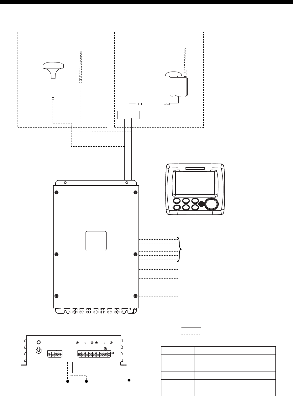
SYSTEM CONFIGURATION
GPS/VHF
combined antenna
GVA-100-T
GPS antenna
GPA-017S
Distributor unit
DB-1
VHF antenna VHF antenna
Power supply
PR-240
100/110/115/200/
220/230 VAC
1
ø, 50/60Hz
12-24 VDC
OR
24 VDC
MONITOR UNIT
FA-1702
(two units may
be connected)
External display, NavNet2,
NavNet 3D, Pilot plug (FA-1703),
Sensor
Beacon receiver
Alarm system
LAN
Blue Sign
GPS-017S Exposed to the weather
GVA-100-T
FA-1701
FA-1702
DB-1
PR-240
Exposed to the weather
Protected from the weather
Protected from the weather
Protected from the weather
Protected from the weather
:
Standard supply
:
Optional or local supply
TRANSPONDER UNIT
FA-1701
SYSTEM CONFIGURATION
x
This page is intentionally left blank.
1-1
1. OPERATION
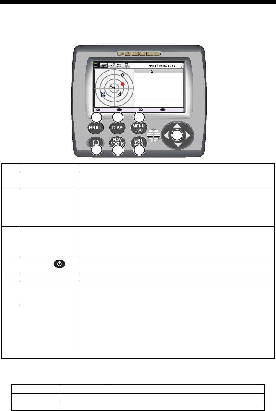
1.1 Description of Controls
Note: The nominal viewing distance is 70 cm.
This manual uses the following terminology for the sake of brevity:
No. Key name Function(s) when pressed
1BRILL key • Displays brilliance setting pop-up window.
• Switches between Day and Night display modes.
2DISP key • Cycles through display screens.
• Switches between Day and Night display modes when brilliance
pop-up window is active.
• Closes all active menu windows and returns to the last used display
screen.
3MENU/ESC key • Opens the menu.
• Goes back one layer in the menu.
• Closes the settings screen, when displayed, and returns to the
menu.
4Power key • Short press to turn the unit on.
• Long press to turn the unit off.
5NAV STATUS key Opens the [NAV STATUS] settings window.
6ENT/ACK key • Confirms the currently selected item on the menu.
• Confirms adjusted settings.
• Acknowledge alerts.
7 Arrow keys • Move the selection cursor.
• Plotter display: or changes display range.
• TARGET LIST display: or changes pages.
• OWN INFORMATION display: or switches between informa-
tion tabs.
• ALERT display: or switches between the alert list and the alert
log. or selects an alert.
Terminology Example Meaning
Select Select [MSG]. Use the arrow keys to select [MSG].
, , , Press . Press the corresponding arrow key.
B
CLASS A
: CURSOR
: SELECT : RANGE
ENT
: NEXT
DISP
MMSI
NAME { NO NAME }
TYPE
POSN
SOG
RNG
HDG
COG
BRG
201502130
130º
135º
225º
10.0kn
3 .0
NM
34º 31
.1234´N
135º 24
.5678´E
A
7
6
1 2 3
45
1. OPERATION
1-2
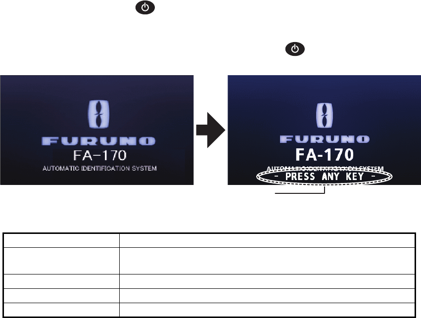
1.2 How to Turn the Power On and Off
Press the power key to turn the equipment on. When powered, the equipment
sounds a beep then proceeds in the sequence shown below.
To turn the power off, press and hold the power key .
The startup screen displays the program version number, serial number and the re-
sults of the ROM and RAM data test, showing "OK" or "NG" (No Good) as the result.
The message "- PRESS ANY KEY -" flashes to indicate that the test is complete.
Press any key to close the test results. If "NG" appears for any of the check results
after the startup test is completed, contact your dealer for advice.
When no errors occur at startup, the plotter display is shown after the test is complet-
ed.
If there is no response from the transponder unit or AIS symbols do not appear, the
message “COMMUNICATION ERROR” appears on the screen. Press any key to
erase the message. Check the connection between the monitor unit and the transpon-
der unit.
The FA-170 should be powered while underway or at anchor. The master may switch
off the AIS if he believes that the continual operation of the AIS might compromise the
safety or security of his ship. The AIS should be restarted when it is safe to do so.
The equipment transmits own ship static data within two minutes of start-up and it is
transmitted at six-minute intervals thereafter. Static data includes MMSI number, IMO
number, call sign, ship name, ship length and width, ship type and GPS antenna po-
sition.
In addition to static data, ship’s dynamic data is also transmitted. This data includes
position with quality indication, SOG, COG, rate of turn, heading, etc. Dynamic data is
transmitted every 2 seconds to 3 minutes depending on ship’s speed and course
change. Voyage-related data, such as ship’s draught, hazardous cargo, destination
and estimated time of arrival, are also transmitted at six-minute intervals.
Indication Description
PROGRAM NUMBER Displays the program number for this FA-170. The indication
"XX.XX" is replaced with the version number.
SERIAL NUMBER Displays the serial number for this FA-170.
ROM(T) / RAM(T) Displays the ROM/RAM test results for the connected FA-1701.
ROM(M) / RAM(M) Displays the ROM/RAM test results for the FA-1702.
PROGRAM NO.
0550255 - xx . xx
1000-42xx - xxxxSERIAL NO.
ROM(T): OK
RAM(T): OK
ROM(M): OK
RAM(M): OK
This indication flashes to show the unit is ready for use. The
automatic startup test results are displayed when tests are
completed.
1. OPERATION
1-3
The FA-170 starts receiving data from AIS-equipped ships as soon as it is turned on,
and those ships’ locations are shown on the plotter display with the AIS symbol. (To
learn more about the plotter display, see section 1.8.) With connection of a radar or
ECDIS, the AIS target symbols may be overlaid on the radar or ECDIS.
Note 1: If no navigation sensor is installed or a sensor such as a gyrocompass has
failed, the AIS automatically transmits “not available data” to AIS-equipped ships.
Note 2: The reporting intervals are as follows:
Note 3: The screen refreshes slower in low ambient temperature.
1.3 How to Adjust the Panel and Display Brilliance
The panel and display brilliance may be adjusted as follows:
1. Press the BRILL key to show the [BRILL LEVEL SETUP] pop up window.
If there is no operation within five seconds, the pop up window automatically clos-
es.
2. Press or to adjust the panel brilliance; or to adjust the display brilliance.
The default panel and display brilliance settings are 15 and 15, respectively. To
restore default settings see "How to Restore Default Settings" on page 3-10.)
Note: The display brilliance can also be adjusted by pressing the BRILL key sev-
eral times to cycle through brilliance levels.
3. Press the ENT/ACK key to close the setting screen and apply the settings.
How to switch between day and night displays
1. Press the BRILL key to show the [BRILL LEVEL SETUP] pop up window.
2. Press the DISP key while the pop up window is shown. The pop up window closes
and the display settings change.
3. Repeat the procedure to reverse the settings.
Ship’s navigational status Nominal reporting interval
Ship at anchor or moored or aground or not under command and
not moving faster than 3 kn
3 minutes
Ship at anchor or moored or aground or not under command and
moving faster than 3 kn
10 seconds
Ship speed 0-14 kn 10 seconds
Ship speed 0-14 kn and changing course 3 1/3 seconds
Ship speed 14-23 kn 6 seconds
Ship speed 14-23 kn and changing course 2 seconds
Ship speed faster than 23 kn 2 seconds
Ship speed faster than 23 kn and changing course 2 seconds
DISPLAY (0 - 17) : 17
PANEL (0 - 17) : 17
: NIGHT : SET
DISP ENT
BRILL LEVEL SETUP (DAY)
1. OPERATION
1-4
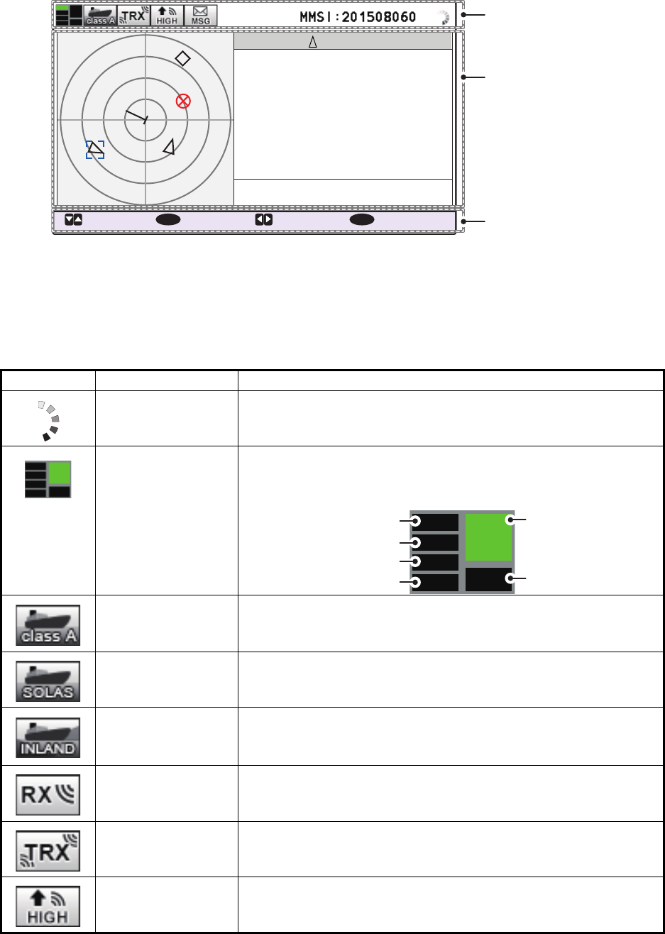
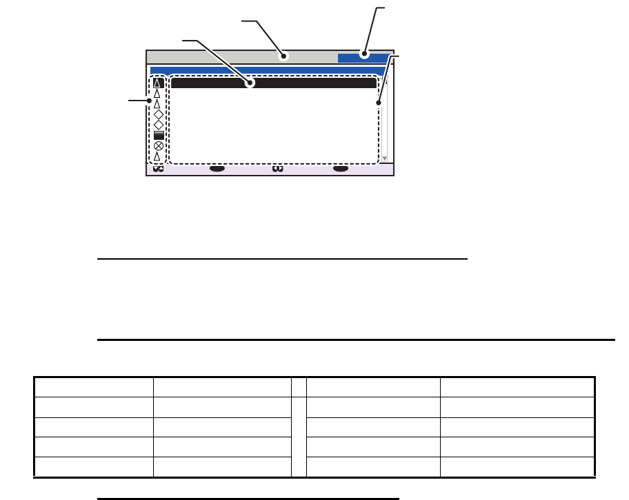
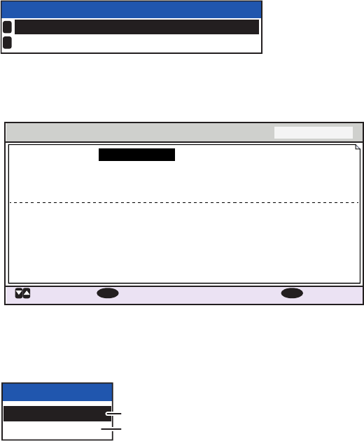
1.4 Display Overview
The FA-170 display is made up of three major areas, as indicated in the Plotter display
example figure below.
The guidance box contents change according to the currently selected display or
menu.
The status bar shows various icons indicating the status of the equipment and shows
the vessel’s own MMSI. The icons which can be displayed in the status bar are listed
in the table below, along with a brief description.
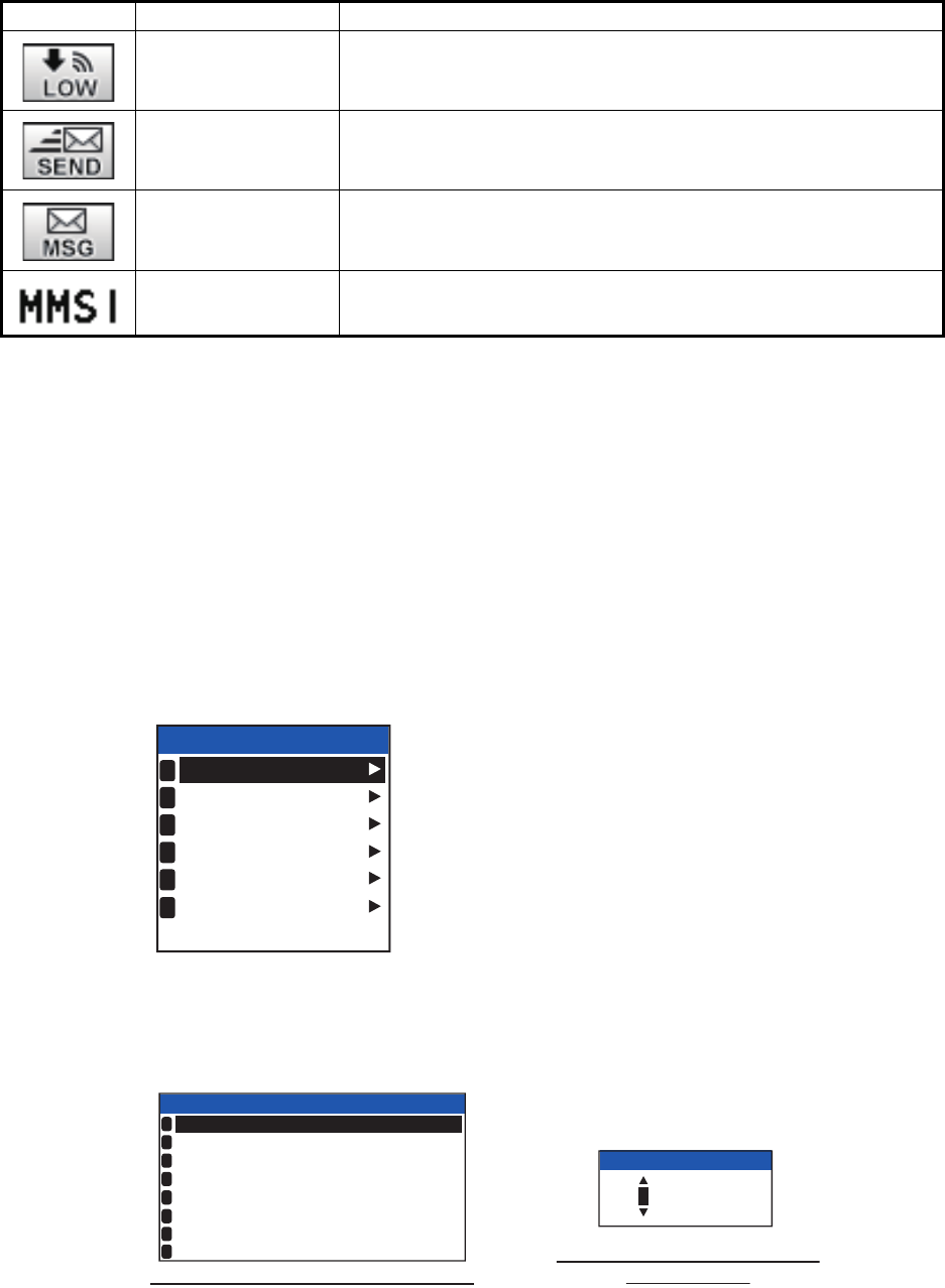
Icon Icon name Description
Operational status The dotted line rotates in a clockwise motion to indicate that the
equipment is working normally.
Contents mini-map Shows the location of the currently selected menu/display, indi-
cated as a green box in the mini-map. The figure below shows
the “locations”, as displayed in the mini-map.
Class A AIS mode Displayed when the equipment is using Class A AIS mode.
SOLAS AIS mode Displayed when the equipment is using SOLAS AIS mode.
INLAND AIS mode Displayed when the equipment is using INLAND AIS mode.
RX (Receive) Displayed when both A and B channel are set to receive mode
(includes OFF). Shown only with CLASS A and INLAND AIS
modes.
TRX (Transmit) Displayed when either channel A or B are set to transmit mode.
Shown only with CLASS A and INLAND AIS modes.
HIGH (power) Displayed when the transmit power level is set to [HIGH].
B
CLASS A
: CURSOR
: FUNC : RANGE
ENT
: NEXT
DISP
MMSI
NAME { NO NAME }
TYPE
POSN
SOG
RNG
HDG
COG
BRG
201502130
130º
135º
225º
10.0kn
3 .0
NM
34º 31
.1234´N
135º 24
.5678´E
A
Status bar
Currently selected display or
menu is shown in the middle
section of the screen.
Guidance box
Plotter
Target list
Own (ship) information
NAV STATUS
Menu
Alert
1. OPERATION
1-5
1.5 Menu Overview
You can access the various functions of your FA-170 from the menu. If you get lost in
operation, press the MENU/ESC key until you return to the main menu. A complete
menu tree is provided in "MENU TREE" on page AP-1.
Note: Inland AIS mode menus may differ from the menus shown in this chapter. For
INLAND AIS mode, see "INLAND AIS OPERATION" on page 2-1.
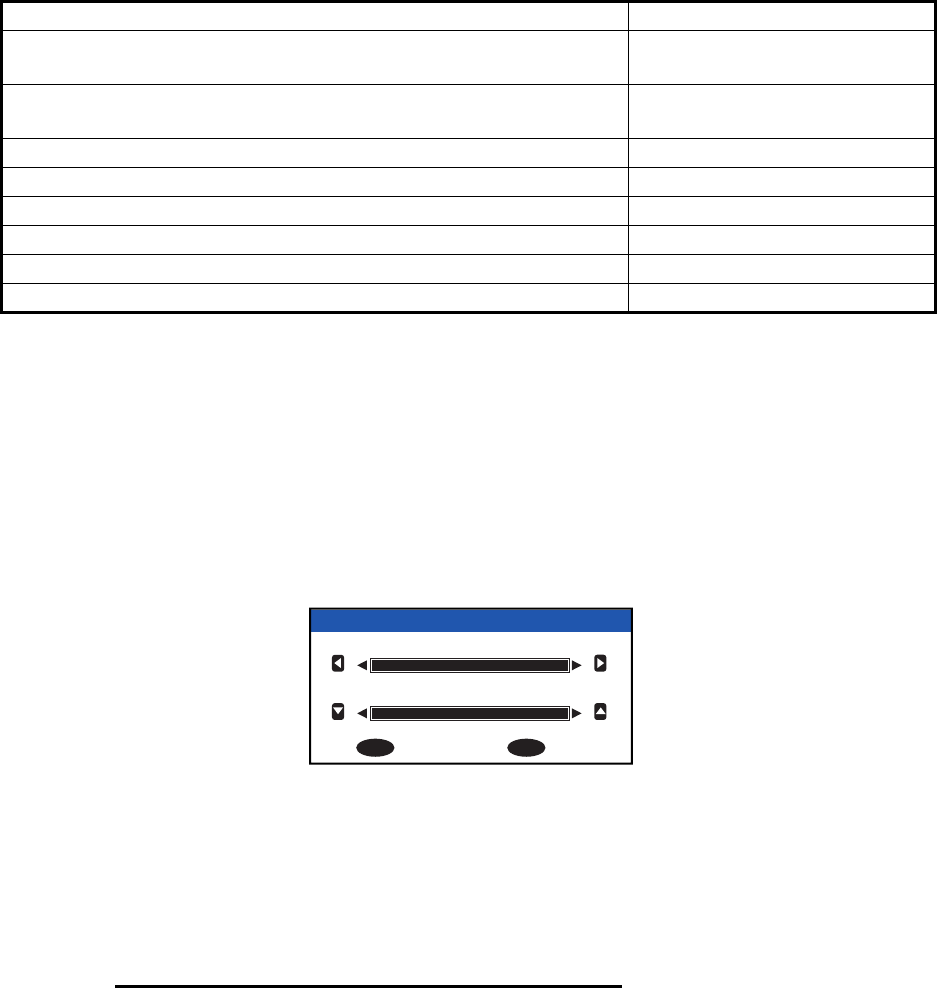
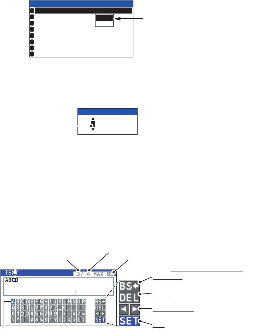
1.5.1 Menu operating procedure
1. Press the MENU/ESC key to display the main menu.
2. Select a main menu item, then press the ENT/ACK key.
3. Select a sub-menu then press the ENT/ACK key.
There are two types of sub-menus: option selection and data input. (Some sub-
menus combine both.) Below are examples of each type of sub-menu.
4. Select a menu item then press the ENT/ACK key.
5. Depending on the menu selected, select an option or input alphanumeric data,
then press the ENT/ACK key.
6. Press the DISP key to close the menu.
LOW (power) Displayed when the transmit power level is set to [LOW].
SEND Displayed during message transmission. Not displayed when
routine messages are transmitted.
MSG Displayed when there are unread messages.
MMSI Own ship MMSI.
Icon Icon name Description
MSG
STATUS
USER SET
INITIAL SET
CH INFO
DIAGNOSTICS
SERVICE
MENU
1
2
3
4
5
6
USER SET sub-menu (Option selection)
TEST TARGET MMSI sub-menu
(Numeric input)
USER SET
ON
ON
HIDE
AUTO
ON
KEY BEEP
TIME DIFF
AUTO SORT
SART TEST
LR RESPONSE
LR BROADCAST
1
2
3
4
5
6
NOTIFICATION SET
7
ACTIVATE
8
:
:
+00:00
:
:
:
:
000000000
TEST TARGET MMSI
1. OPERATION
1-6
1.5.2 How to select a menu option
The example below shows how to select an option from a menu.
1) A window showing the options for the item selected is overlaid on the sub-menu.
For example, the options for [KEY BEEP] are as shown below.
2) Press or to select option desired, then press the ENT/ACK key.
1.5.3 How to enter numeric data
The example below shows how to enter numeric data.
1) Select the appropriate numeric character. Press to display numeric characters
cyclically in ascending order. Press to display numeric characters cyclically in
descending order.
2) Press or to shift the cursor.
3) Repeat steps 1) and 2) to finish entering data.
4) After entering all data, press the ENT/ACK key to register input.
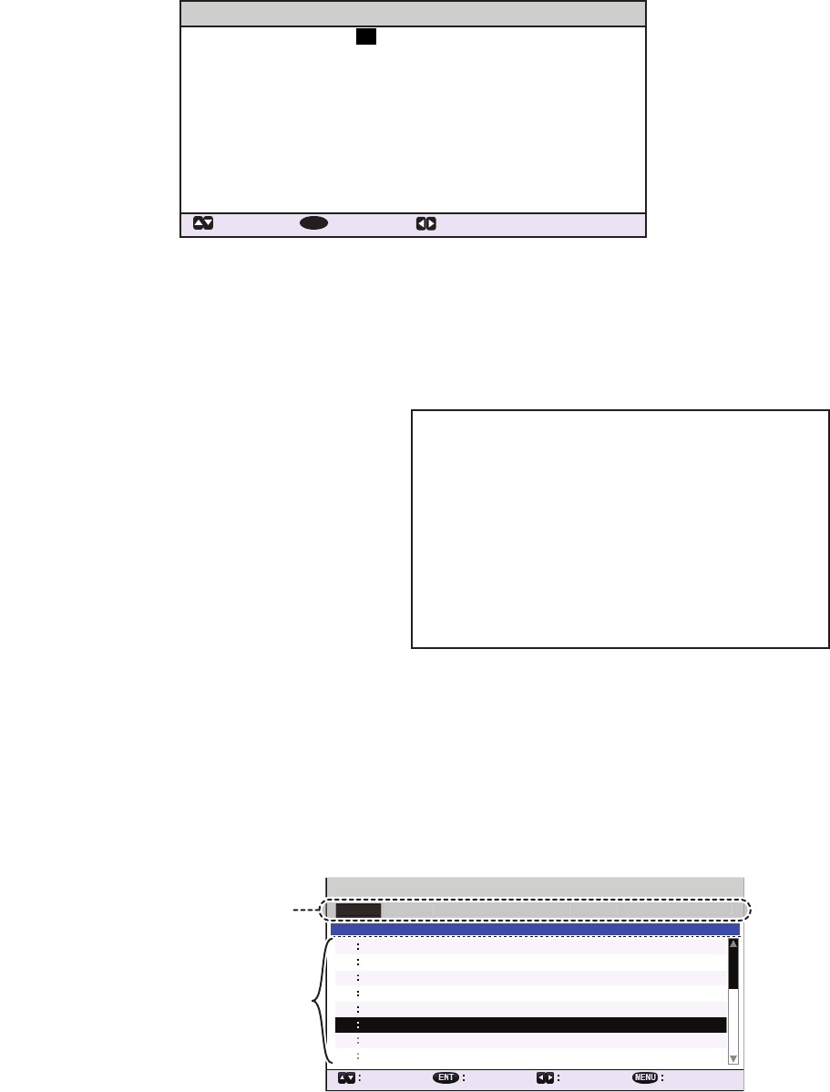
1.5.4 How to use the software keyboard for alphanumeric input
The software keyboard appears when alphanumeric input is possible. Software key-
board operation requires the use of the arrow keys and the ENT/ACK key.
1. Referring to the figure above, press the arrow keys to select a character or key-
board operation.
2. Press the ENT/ACK key to confirm your selection.
3. Repeat steps 1 and 2 to completed the alphanumeric input.
4. Select [SET], then press the ENT/ACK key.
ON
OFF
USER SET
ON
HIDE
AUTO
ON
KEY BEEP
TIME DIFF
AUTO SORT
SART TEST
LR RESPONSE
LR BROADCAST
1
2
3
4
5
6
NOTIFICATION SET
7
ACTIVATE
8
:
:
:
:
Options
window
000000000
TEST TARGET MMSI
Cursor position
is highlighted.
Cursor position is
shown as a blue bar.
Backspace - Erase the character to the
left of the cursor.
Delete - Erase the character to the right
of the cursor.
Cursor locators - Press ► to move the
cursor right, ◄ to move the cursor left.
SET - Apply the changes.
Current selection is highlighted in blue.
Keyboard operation keys
No. of characters
before cursor
Total characters input
Maximum characters allowed
1. OPERATION
1-7
1.6 How to Enter Voyage-Related Data
There are six items on the [NAV STATUS] menu that you will need to enter at the start
of a voyage.
1. Press the NAV STATUS key to open the [NAV STATUS] menu.
The [NAV STATUS] setting is selected by default
2. If your navigational status is different from that shown, follow the procedure below.
If it is the same as shown, go to step 3.
1) Press the ENT/ACK key. The [NAV STATUS] options pop up window appears.
2) Input the appropriate status, then press the ENT/ACK key. Refer to the data
below to select appropriate navigational status.
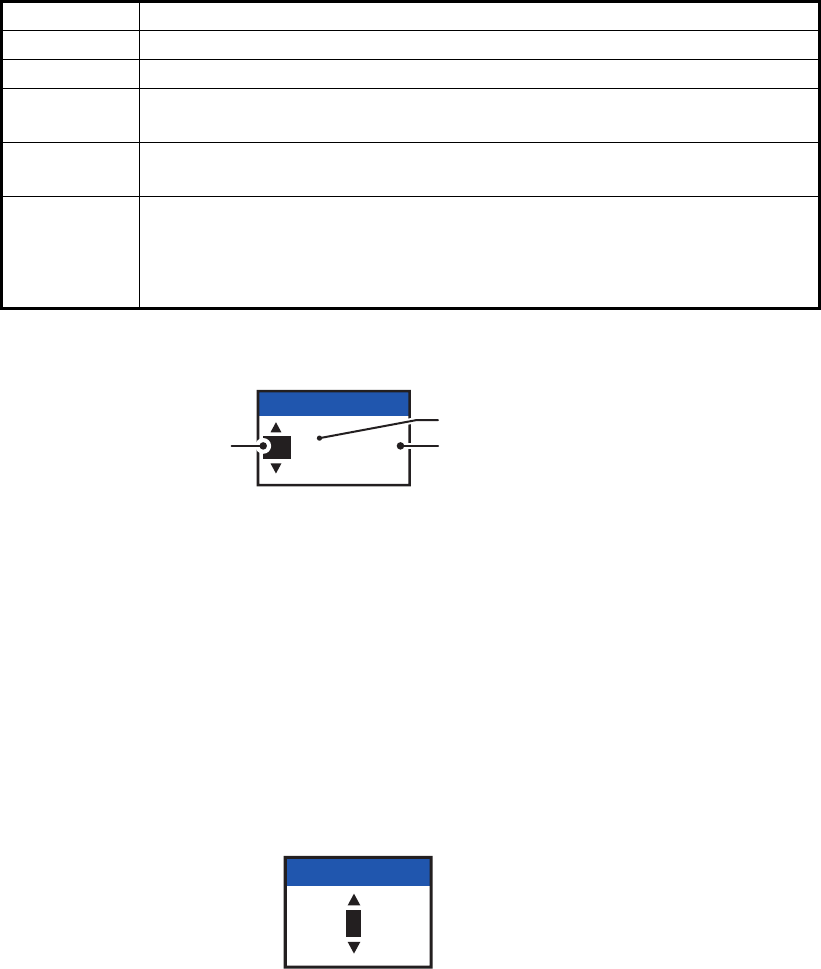
3. Select [DESTINATION], then press the ENT/ACK key. The software keyboard ap-
pears for direct input.
Enter the desired destination then press the ENT/ACK key. You can use up to 20
alphanumeric characters and enter up to 20 destinations.
A list of destinations can also be accessed by selecting [DESTINATION LIST].
• Navigational Status • Cargo type • ETA(LT/UTC) (Arrival time)
• Destination • No. of persons • Draught
NAV STATUS
NAV STATUS PWR-DRIVEN VESSEL PUSHING
AHEAD OR TOWING ALONGSIDE
KOBE
[DESTINATION LIST]
DESTINATION
ETA[UTC]12/MAY 12:32
24 WIG
CARRYING DG, HS, OR,
MP(OS)
CARGO TYPE
DRAUGHT 0 . 0m
1NO. OF PERSONS
: CURSOR
: SELECT
12
ENT
:
:
:
:
:
:
: TAB
00: UNDERWAY USING ENGINE
01: AT ANCHOR
02: NOT UNDER COMMAND
03: RESTRICTED MANEUVERABILITY
04: CONSTRAINED BY HER DRAUGHT
05: MOORED
06: AGROUND
07: ENGAGED IN FISHING
08: UNDERWAY SAILING
09: RESERVED FOR HIGH SPEED CRAFT (HSC)*
1
10: RESERVED FOR WING IN GROUND (WIG)*
2
11: PWR-DRIVEN VESSEL TOWING ASTERN
12: PWR-DRIVEN VESSEL PUSHING AHEAD OR TOWING ALONGSIDE
13: RESERVED FOR FUTURE USE
14: AIS-SART (ACTIVE), MOB-AIS, EPIRB-AIS*
3
15: DEFAULT (ALSO USED BY SART, MOB, EPIRB UNDER TEST)
*1: RESERVED FOR FUTURE AMENDMENT OF
NAVIGATIONAL STATUS FOR SHIPS CARRYING DG, HS,
OR MP, OR IMO HAZARD OR POLLUTANT CATEGORY C,
HIGH SPEED CRAFT (HSC)
*2: RESERVED FOR FUTURE AMENDMENT OF
NAVIGATIONAL STATUS FOR SHIPS CARRYING
DANGEROUS GOODS (DG), HARMFUL SUBSTANCES
(HS) OR MARINE POLLUTANTS (MP), OR IMO HAZARD
OR POLLUTANT CATEGORY A, WING IN GRAND (WIG)
*3: Not selectable for this type of equipment.
DESTINATION LIST
<EDIT>
SEATTLE
OSAKA
SAN FRANCISCO
YOKOHAMA
BRISBANE
= NO ENTRY =
= NO ENTRY =
07
06
05
04
03
02
01
01 / 20
08
DESTINATION
ABERDEEN
<COPY>
CURSOR
EXEC FUNC
BACK
<PASTE>
<CUT>
<SET>
Operation selection bar
<
EDIT
>
<COPY
>
<
PASTE
>
<CUT>
<SET
>
Destinations
1. OPERATION
1-8
Referring to operation descriptions in the table below, press or to select an
operation, press or to select an entry in the list, then press the ENT/ACK key
to confirm the selection.
4. Select [ETA (LT/UTC)], then press the ENT/ACK key. The settings pop up window
shown below appears.
Note 1: The ETA indication appears as "ETA [LT]" when there a time offset is set
from [TIME DIFF] in the [USER SET] menu. When the setting for [TIME DIFF] is
not changed from the default (+00:00) setting, the ETA indication appears as
"ETA [UTC]".
Note 2: Where a GPS is not connected, or the signal is lost/interrupted, the ETA
indication appears as ETA [UTC]. Further, the settings pop up window displays
"NOTE: INPUT THE UTC" at the bottom of the pop up window.
5. Set the ETA date and time, referring to the figure above, then press the ENT/ACK
key.
6. Select [CARGO TYPE], then press the ENT/ACK key. The settings pop up win-
dow shown below appears.
7. Select type of vessel/cargo, referring to the table on the following page, then press
the ENT/ACK key.
Note 1: Only the second digit for the type of vessel is entered here; the first digit
is entered on the [INITIAL SET] menu, during installation.
Note 2: When [Tanker] is selected and the Nav status is [Moored], output power
is automatically switched to 1 W when SOG is less than 3 knots. Further, in the
above condition, when SOG becomes higher than 3 knots, a beep sounds. (The
pop-up message "TX POWER CHANGED" also appears to notify you that the Tx
power has changed). To erase the pop-up message, press the ENT/ACK key or
reduce SOG to below 3 knots.
Operation Description
<SET> Set the currently selection as the destination.
<EDIT> Rename the selected destination.
<CUT> Cut the current selection to temporary memory, leaving the entry empty.
The destination can now be pasted as a different entry.
<COPY> Copy the current selection to temporary memory. The destination can
now be pasted as a different entry.
<PASTE> Paste the entry in temporary memory.
Note 1: Only one entry can be stored in temporary memory at a time. If
you <CUT> two entries successively, the first is deleted.
Note 2: Entries over-written with <PASTE> cannot be restored.
12 / 10 12:32
ETA (UTC)
ETA month
ETA day ETA time
in 24hr format
24
CARGO TYPE

1. OPERATION
1-9
8. Select [DRAUGHT], then press the ENT/ACK key.
9. Input the ship’s draught (setting range: 0 m to 25.5 m) then press the ENT/ACK
key.
10. Select [NO. OF PERSONS], then press the ENT/ACK key.
11. Input total number of persons aboard the ship (setting range: 0-8191) then press
the ENT/ACK key. Enter 8191 for total greater than 8190.
12. Press the DISP key to close the menu.
WIG: Wing in ground
HSC: High speed craft
DG: Dangerous goods
HS: Harmful substances
MP: Marine pollutants
0-9: Undefined
10 FUTURE USE ALL SHIPS OF THIS TYPE 60 PASSENGER SHIPS
A
LL SHIPS OF THIS TYPE
11 FUTURE USE CARRYING DG, HS, OR MP(X) 61 PASSENGER SHIPS CARRYING DG, HS, OR MP(X)
12 FUTURE USE CARRYING DG, HS, OR MP(Y) 62 PASSENGER SHIPS CARRYING DG, HS, OR MP(Y)
13 FUTURE USE CARRYING DG, HS, OR MP(Z) 63 PASSENGER SHIPS CARRYING DG, HS, OR MP(Z )
14 FUTURE USE CARRYING DG, HS, OR MP(OS) 64 PASSENGER SHIPS CARRYING DG, HS, OR MP(OS)
15 FUTURE USE 65 PASSENGER SHIPS FUTURE USE
16 FUTURE USE 66 PASSENGER SHIPS FUTURE USE
17 FUTURE USE 67 PASSENGER SHIPS FUTURE USE
18 FUTURE USE 68 PASSENGER SHIPS FUTURE USE
19 FUTURE USE NO ADDITIONAL INFORMATION 69 PASSENGER SHIPS NO ADDITIONAL INFORMATION
20 WIG
A
LL SHIPS OF THIS TYPE 70 CARGO SHIPS
A
LL SHIPS OF THIS TYPE
21 WIG CARRYING DG, HS, OR MP(X) 71 CARGO SHIPS CARRYING DG, HS, OR MP(X)
22 WIG CARRYING DG, HS, OR MP(Y) 72 CARGO SHIPS CARRYING DG, HS, OR MP(Y)
23 WIG CARRYING DG, HS, OR MP(Z ) 73 CARGO SHIPS CARRYING DG, HS, OR MP(Z )
24 WIG CARRYING DG, HS, OR MP(OS) 74 CARGO SHIPS CARRYING DG, HS, OR MP(OS)
25 WIG FUTURE USE 75 CARGO SHIPS FUTURE USE
26 WIG FUTURE USE 76 CARGO SHIPS FUTURE USE
27 WIG FUTURE USE 77 CARGO SHIPS FUTURE USE
28 WIG FUTURE USE 78 CARGO SHIPS FUTURE USE
29 WIG NO ADDITIONAL INFORMATION
NO ADDITIONAL INFORMATION
79 CARGO SHIPS NO ADDITIONAL INFORMATION
30 FISHING 80 TANKER(S)
TANKER(S)
TANKER(S)
TANKER(S)
TANKER(S)
TANKER(S)
TANKER(S)
TANKER(S)
TANKER(S)
TANKER(S)
A
LL SHIPS OF THIS TYPE
31 TOWING 81 CARRYING DG, HS, OR MP(X)
32 LENGTH OF THE TOW EXCEEDS 200M OR BREADTH EXCEEDS 25M 82 CARRYING DG, HS, OR MP(Y)
33 ENGAGED IN DREDGING OR UNDERWATER OPERATIONS 83 CARRYING DG, HS, OR MP(Z)
34 ENGAGED IN DIVING OPERATIONS 84 CARRYING DG, HS, OR MP(OS)
35 ENGAGED IN MILITARY OPER ATIONS 85 FUTURE USE
36 SAILING 86 FUTURE USE
37 PLEASURE CRAFT 87 FUTURE USE
38 FUTURE USE 88 FUTURE USE
39 FUTURE USE 89 NO ADDITIONAL INFORMATION
40 HSC
A
LL SHIPS OF THIS TYPE 90 OTHER TYPE OF SHIP
A
LL SHIPS OF THIS TYPE
41 HSC CARRYING DG, HS, OR MP(X) 91 OTHER TYPE OF SHIP
42 HSC CARRYING DG, HS, OR MP(Y) 92 OTHER TYPE OF SHIP
43 HSC CARRYING DG, HS, OR MP(Z ) 93 OTHER TYPE OF SHIP )
44 HSC CARRYING DG, HS, OR MP(OS) 94 OTHER TYPE OF SHIP
45 HSC FUTURE USE 95 OTHER TYPE OF SHIP
46 HSC FUTURE USE 96 OTHER TYPE OF SHIP
47 HSC FUTURE USE 97 OTHER TYPE OF SHIP
48 HSC FUTURE USE 98 OTHER TYPE OF SHIP
49 HSC 99 OTHER TYPE OF SHIP
CARRYING DG, HS, OR MP(X)
CARRYING DG, HS, OR MP(Y)
CARRYING DG, HS, OR MP(Z
CARRYING DG, HS, OR MP(OS)
FUTURE USE
FUTURE USE
FUTURE USE
FUTURE USE
50 PILOT VESSEL
51 SEARCH AND RESCUE VESSELS
52 TUGS
53 PORT TENDERS
54 VESSELS WITH ANTI-POLLUTION FACILITIES OR EQUIPMENT
55 LAW ENFORCEMENT VESSELS
56 SPARE-FOR ASSIGNMENTS TO LOCAL VESSELS
57 SPARE-FOR ASSIGNMENTS TO LOCAL VESSELS
58 MEDICAL TRANSPORTS
59
SHIPS & AIRCRAFT OF STATES NOT PARTIES TO AN ARMED CONFLICT
NO ADDITIONAL INFORMATION
00 .0
DRAUGHT
0001
NO. OF PERSONS
1. OPERATION
1-10
1.7 How to Set the Notification
The [NOTIFICATION SET] menu is used to set the following items:
• Enable or disable the alert buzzer.
• Notifications for received [ADDRESSED] and [BROADCAST] messages.
• Notifications for collision detection.
To change the settings in the [NOTIFICATION SET] menu, do the following:
1. Press the MENU/ESC key to open the main menu.
2. Select [USER SET], then press
the ENT/ACK key.
3. Select [NOTIFICATION SET],
then press the ENT/ACK key.
The [NOTIFICATION SET]
screen appears.
4. Select the [BUZZER] item be-
low [ALERT], then press the
ENT/ACK key. The settings
pop up window appears.
5. Select [ON] to enable the alert buzzer, or select [OFF] to disable the alert buzzer,
then press the ENT/ACK to confirm the setting.
6. Select the [ADDRESSED] item below [RX MESSAGE], then press the ENT/ACK
key. The settings pop up window appears.
7. Select the appropriate setting, referring to the table below, then press the ENT/
ACK key.
8. Set the notifications for [BROADCAST] RX messages and [COLLISION DETECT]
in the same manner.
9. Press the DISP key to close the menu.
Setting Description
POPUP + BUZZER Enable both the pop up indication and the buzzer.
POPUP Enable only the pop up indication. (No buzzer.)
OFF Disable notifications.
NOTIFICATION SET
[ALERT]
ADDRESSED
BUZZER
BROADCAST
[RX MESSAGE]
[COLLISION DETECT ]
INDICATION
: CURSOR
: SELECT : BACK
ON
POPUP
POPUP + BUZZER
POPUP
ENT ENT
:
:
:
:
1. OPERATION
1-11
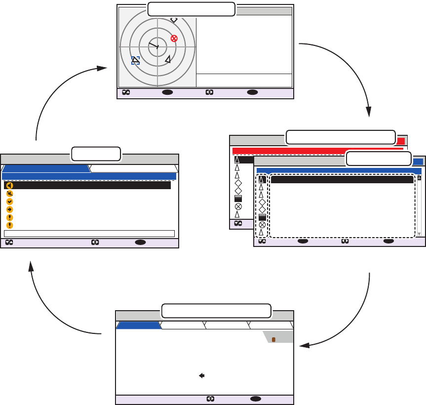
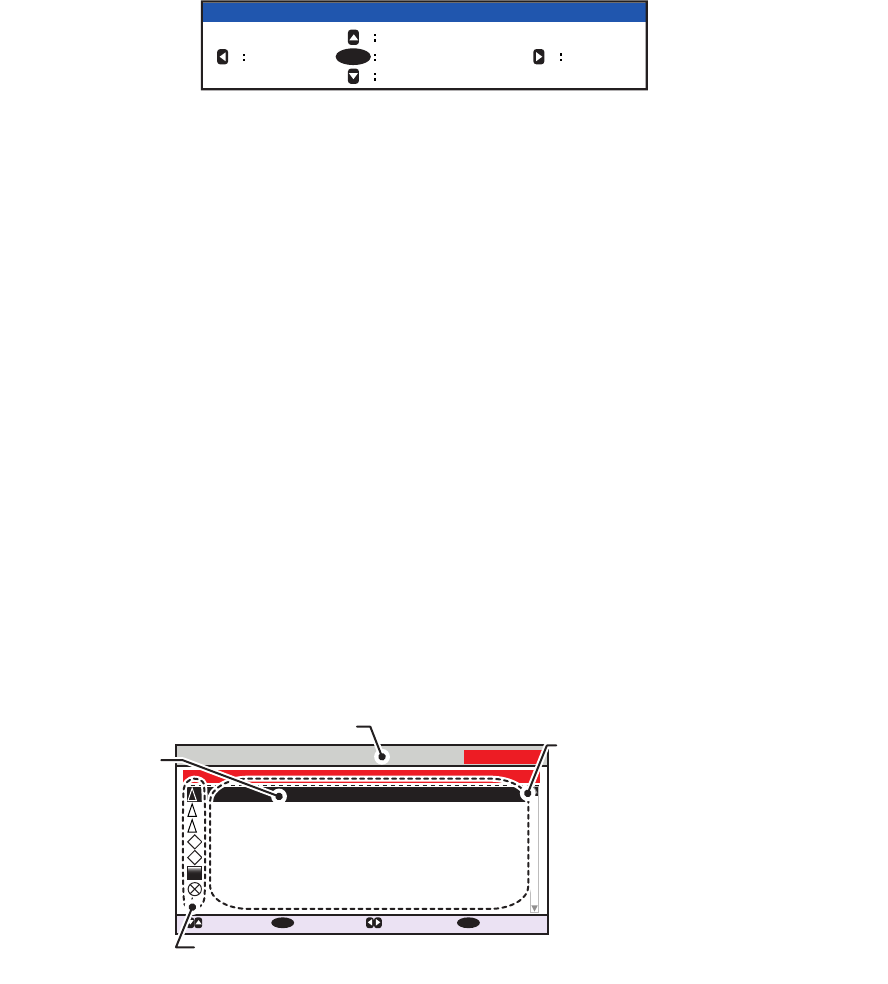
1.8 How to Select a Display
Use the DISP key to select a display. Each time the key is pressed, the display chang-
es in the sequence shown below.
The [DANGEROUS LIST] and [TARGET LIST] are displayed dependent on which list
was last displayed. For example, if the [DANGEROUS LIST] is viewed at any time, the
[TARGET LIST] is hidden in the above cycle and can only be viewed by sorting the
[DANGEROUS LIST]. See section 1.8.2 for details.
DANGEROUS LIST 12:32:01
9-16 (108)
: CURSOR
: FUNC
ENT
: PAGE : NEXT
DISP
SAMPLE SHIP 003 3 .5 100.0 0
SAMPLE SHIP 004 3 .6 110.0
SAMPLE SHIP 005 3 .7 120.0 0
SAMPLE SHIP 006 3 .8 130.0 0
SAMPLE SHIP 007 3 .9 140.0 0
SAMPLE SHIP 008 3 .1 150.0 0
SAMPLE SHIP 002 3 .4 090.0 0
SAMPLE SHIP 002 3 .3 080.0 0
NAME/MMSI/TYPE
RNG[NM] BRG[ ° ] AGE[ ‘
]
B
A
A
SAR
B
ALERT
: CURSOR
: TAB : NEXT
DISP
30/ JAN 17:20 TX MALFUNCTION
29/ JAN 17:50 ANTENNA VSWR EXCEEDS LIMIT
28/ JAN 08:20 RX CHANNEL 1 MALFUNCTION
27/ JAN 12:35 RX CHANNEL 2 MALFUNCTION
26/ JAN 03:45 GENERAL FAILURE
25/ JAN 09:36 ACTIVE AIS-SART
ID:001 : TX MALFUNCTION
TIME [UTC] ALERT 01 /06
LIST : 6 LOG : 20
OWN INFORMATION
: TAB : NEXT
DISP
SENSOR VOYAGE IDENTITY SCALE
UTC
12/NOV/2014 17 :20 :00
34 º 44 .5000 ´N
130º
135 .0º
135 º 21.3000 ´E
108 . 7 º/min ( )
10 .0 kn
HIGH
UNUSED
POSN PA
RAIM
HDG
COG
ROT
SOG
EXTERNAL
DGPS
2
Dangerous target list
Note: The last displayed list is shown.
B
CLASS A
: CURSOR
: SELECT : RANGE
ENT
: NEXT
DISP
MMSI
NAME { NO NAME }
TYPE
POSN
SOG
RNG
HDG
COG
BRG
201502130
130º
135º
225º
10.0kn
3 .0
NM
34º 31
.1234´N
135º 24
.5678´E
A
Alert list
Own (ship) information
TARGET LIST
12:32:01
81-88(334)
: CURSOR
: FUNC
ENT
: PAGE : NEXT
DISP
NAME/MMSI/TYPE
RNG[NM] BRG[ º ] AGE[ ‘
]
B
A
A
SAR
B
SAMPLE SHIP 003 3 .5 100.0 0
SAMPLE SHIP 004 3 .6 110.0
SAMPLE SHIP 005 3 .7 120.0 0
SAMPLE SHIP 006 3 .8 130.0 0
SAMPLE SHIP 007 3 .9 140.0 0
SAMPLE SHIP 008 3 .1 150.0 0
SAMPLE SHIP 002 3 .4 090.0 0
SAMPLE SHIP 002 3 .3 080.0 0
Target list
Plotter display
1. OPERATION
1-12
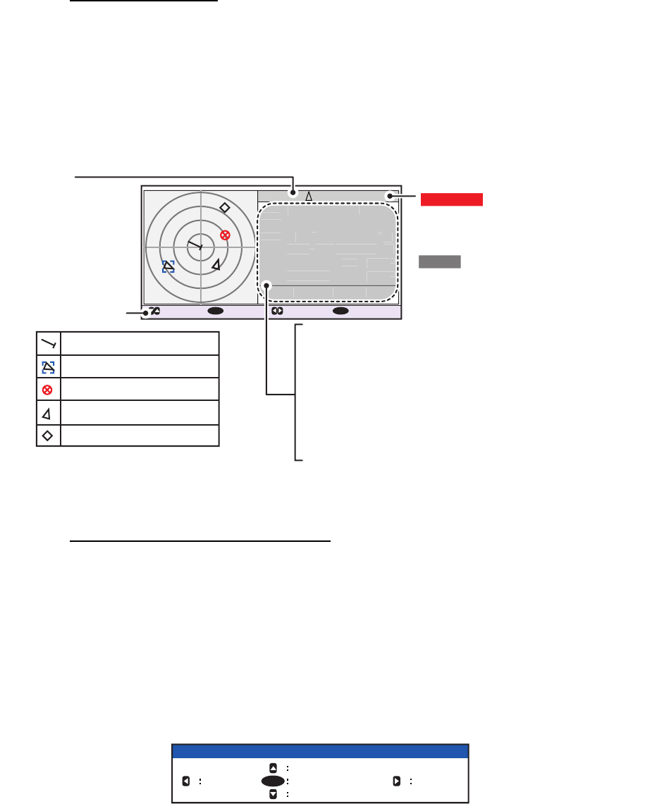
1.8.1 Plotter display
The plotter display, which automatically appears after the power-on sequence, shows
various information for AIS-equipped ships, AIS-SARTs, etc. within the range select-
ed.
Data for ship target
A target marker (hollow triangle) indicates the presence of a vessel equipped with AIS
in a certain location and course. To view detailed information about a vessel, see
paragraph 1.8.2.
If two or more targets occupy a similar position, the display priority order is: selected
target (surrounded by a broken box, as shown in the example below) > non-selected
target.
How to operate the plotter display
1. Press the DISP key to show the plotter display.
2. Press or to select a range. The available ranges are (in nm): 0.125, 0.25, 0.5,
0.75, 1.5, 3, 6, 12, and 24.
3. Press or to select a target. The selected target is highlighted in a blue col-
ored broken box. Further, the selected target’s basic data are displayed on the
right-side of the screen.
4. To view a target’s detailed data, or to sort the target list, select the desired target,
then press the ENT/ACK key. The [FUNCTION] pop up window appears.
• [SORT (NORMAL)]: Press to display and sort the [TARGET LIST] into range
order.
DANGER is displayed here when a
target is calculated to be on a
collision course with your vessel. If
no signal is received from target,
LOST is displayed. The target data
is deleted seven minutes after the
loss of signal from the target.
: FUNC : RANGE
ENT
: NEXT
DISP
B
CLASS A
MMSI
NAME { NO NAME }
TYPE
POSN
SOG
RNG
HDG
COG
BRG
201502130
130º
135º
225º
10.0kn
3 .0
NM
34º 31
.1234´N
135º 24
.5678´E
A
MMSI: Target’s MMSI
NAME: Target vessel’s name (if available)
POSN: Target’s last known position
HDG: Target’s heading
SOG: Target’s Speed Over Ground
COG: Target’s Course Over Ground
RNG: Range to target from Own Ship
BRG: Bearing to target
Target type
(CLASS A, CLASS B,
BS, AtoN, SAR,
AIS-SART, MOB-AIS,
EPIRB-AIS, INLAND)
MMSI
NAME
{
NO NAME
}
P
OSN
SOG
RNG
H
D
G
C
OG
B
R
G
201
5
02130
130
º
135
º
22
5
º
10
.
0
kn
3
.
0
NM
3
4
º
3
1
.
12
34
´
N
1
3
5
º
24
.
567
8
´
E
Key guidance bar
Selected target
Own Ship symbol
AIS-SART
Target (black)
Base station
B
For a full list of AIS icons, and their
meanings, see Appendix 5, at the
back of this manual.
: CURSOR
FUNCTION
NEW MSG
VIEW DETAIL SORT
(DANGER)
SORT
(NORMAL)NAME REQUEST
ENT
1. OPERATION
1-13
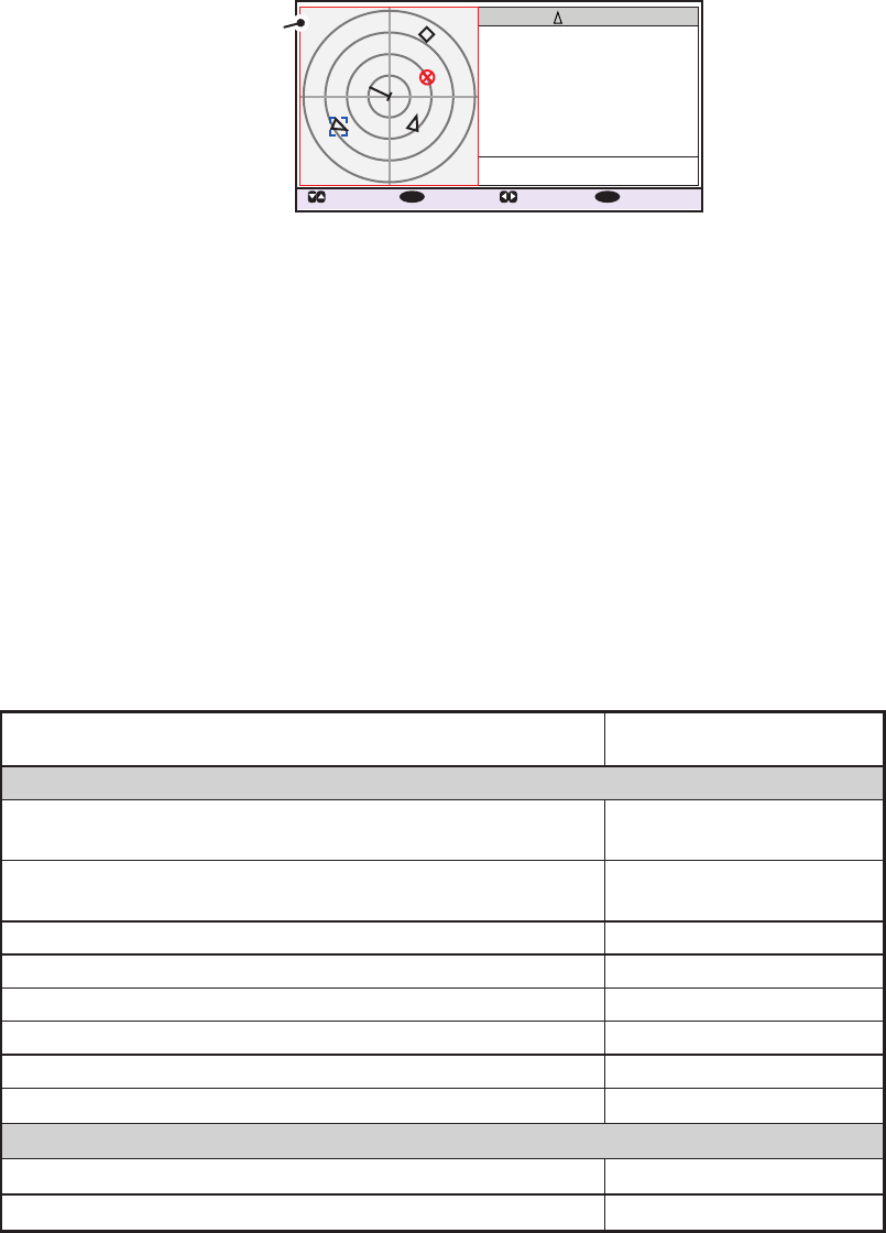
• [SORT (DANGER)]: Press to display and sort the [DANGEROUS TARGET
LIST] in range order.
Note: When [SORT (DANGER)] is selected, all non-dangerous targets are hid-
den on the plotter display and the plotter screen is surrounded by a red box, as
shown in the figure below.
To show any targets which were hidden by this option, select [SORT (NOR-
MAL)] from the [FUNCTION] pop up window.
• [VIEW DETAIL]: Press the ENT/ACK key to open the [TARGET DETAIL]
screen.
• [NEW MSG]: Press to open the text input window to create an AIS message
to the selected target.
• [NAME REQUEST]: Press to send a name request to the target vessel’s AIS.
Note: Name requests cannot be sent to the same target within a short period,
regardless of target. If you have requested the name of a target too soon after
the last request, the pop up message "CANNOT REQUEST NAME" appears.
Wait a short while before requesting the name again.
Note 1: A target is declared a lost target under the conditions shown in the table be-
low. A target is erased from the screen seven minutes (For AIS-SART, 18 minutes)
after no signal is received from the target.
Note 2: When a target is considered to be on a collision course, the audible alert
sounds (if active). Take suitable measures to avoid collision.
Note 3: "DANGER" appears next to the target type when a target is considered to be
on a collision course. Further, when a target becomes a lost target, "LOST" appears
next to the target type.
CLASS A
: CURSOR
: SELECT : RANGE
ENT
: NEXT
DISP
MMSI
NAME { NO NAME }
TYPE
POSN
SOG
RNG
HDG
COG
BRG
201502130
130º
135º
225º
10.0kn
3 .0
NM
34º 31
.1234´N
135º 24
.5678´E
A
B
Plotter surrounded
by red line. Only
dangerous targets
are displayed.
Ship’s navigational status Target declared as
lost target after:
Class A
Class B
Ship at anchor or moored or aground or not under
command and not moving faster than 3 kn.
Ship at anchor or moored or aground or not under
command and moving at more than 3 kn.
0 to 14 kn speed
0 to 14 kn speed with course change
50 seconds
50 seconds
14 to 12 kn speed 30 seconds
14 to 12 kn speed with course change 30 seconds
Speed higher than 23 kn 10 seconds
Speed over ground less than 2 kn 7 minutes
Speed over ground 2 kn or higher 150 seconds
Speed higher than 23 kn with course change 10 seconds
50 seconds
7 minutes
1. OPERATION
1-14
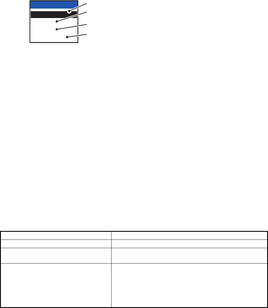
1.8.2 Target list
The [TARGET LIST] can store up to 2048 AIS targets and AIS-SARTs being detected
by the FA-170 across several pages, in the order which they are detected. The list can
be sorted in range order, from closest to farthest.
Note: The last viewed list is displayed when the DISP key is pressed to show either
the [TARGET LIST] or the [DANGEROUS LIST]. To view the [TARGET LIST] when
the [DANGEROUS LIST] is displayed, follow the procedure outlined in step 3 on the
following page.
1. Press the DISP key until the [TARGET LIST] is displayed.
The [NAME/MMSI/TYPE] column of the [TARGET LIST] displays the target ves-
sel’s type in the following formats:
Where the target type is CLASS A/CLASS B/AtoN
The name of the vessel is displayed when the name data is available. Where the
name data is not available, the vessel’s MMSI is displayed.
Where the target type is SAR(VESSEL/AIRCRAFT)/SART/MOB/EPIRB
The format in which data is displayed is listed in the table below.
Where the target type is BASE STATION
"BS:(Base station’s MMSI)" is displayed.
Note 1: If there is no data for the target selected, the fields are displayed as "=NO
TARGET=".
Note 2: Targets are automatically sorted in range order (closest to furthest) when
no key is operated for 30 seconds. Target order is then updated every five sec-
onds.
Active AIS-SARTs take priority and are displayed at the top of the list.
Note 3: When [AUTO SORT] on the [USER SET] menu is [OFF], the range and
bearing to a target are updated. However, target order is not updated. To manu-
ally sort targets, see step 2.
Note 4: To select a target on the plotter display, press or to select the target
then press the ENT/ACK key. Press to cycle through targets from nearest to
furthest; to cycle through targets from furthest to nearest.
TYPE Display format TYPE Display format
SAR vessel "SAR/VESSEL" MOB Active "MOB ACTIVE"
SAR aircraft "SAR/AIRCRAFT" MOB Test "MOB TEST"
SART Active "SART ACTIVE" EPIRB Active "EPIRB ACTIVE"
SART Test "SART TEST" EPIRB Test "EPIRB TEST"
TARGET LIST 12:32:01
81-88(334)
: CURSOR
: FUNC
ENT
: PAGE : NEXT
DISP
NAME/MMSI/TYPE
RNG[km] BRG[ º ] AGE[ ‘
]
B
A
A
SAR
B
SAMPLE SHIP 003 3 .5 100.0 0
SAMPLE SHIP 004 3 .6 110.0
SAMPLE SHIP 005 3 .7 120.0 0
SAMPLE SHIP 006 3 .8 130.0 0
SAMPLE SHIP 007 3 .9 140.0 0
SAMPLE SHIP 008 3 .1 150.0 0
SAMPLE SHIP 002 3 .4 090.0 0
SAMPLE SHIP 002 3 .3 080.0 0
NAME/MMSI/TYPE: Target’s MMSI,
name or type is displayed. Where
name data is available, the vessel
name is displayed.
RNG[km]: Range from OS to target.
BRG[ º ]: Bearing to target.
AGE[ ‘ ]: Time (in minutes) since the
target data was last updated.
Target type symbols.
See Appendix 5 of the
operator’s manual for a
full list of AIS symbols
and their meanings.
Selected target is highlighted.
Time at which the list was last sorted.
Currently displayed target group.
Total detected targets is displayed in
brackets.
1. OPERATION
1-15
2. Press or to scroll through the first 100 targets, press or to scroll through
the targets in groups of 8 (next/previous 8 targets).
The indication "NEXT 100 TARGETS" appears at the bottom of the list if more tar-
gets are available. Select the indication, then press the ENT/ACK key to show the
next 100 targets.
The indication "PREVIOUS 100 TARGETS" appears at the top of the list if there
is one or more pages of targets before the one currently displayed. Select the in-
dication, then press the ENT/ACK key to show the previous 100 targets.
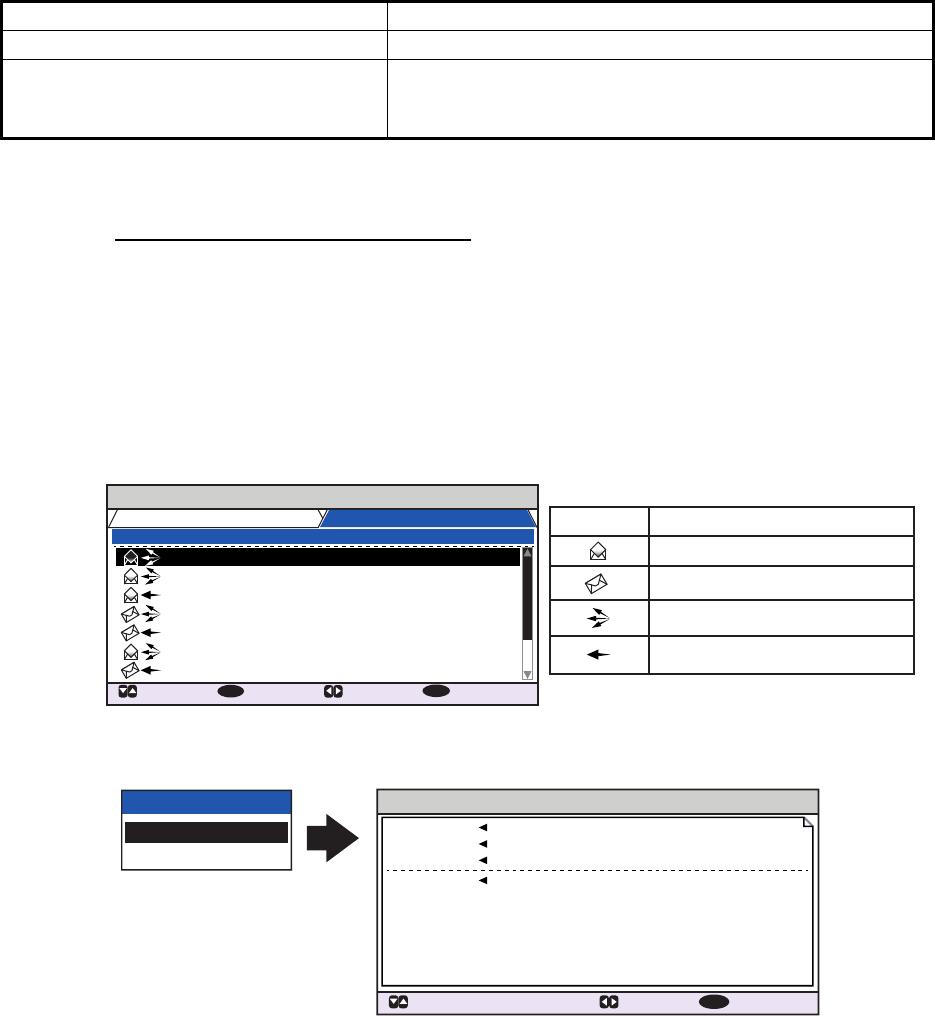
3. To view target data, or to sort the target list, select the desired target, then press
the ENT/ACK key. The target list options pop up window is displayed.
4. Press the DISP key to close the menu.
1.8.3 Dangerous (target) list
Dangerous targets are targets which are calculated to be on a collision course with
your vessel. When a dangerous target is detected, the target and its available details
can be viewed in the [DANGEROUS TARGET LIST].
Note: The operations available from the [DANGEOUS TARGET LIST] are the same
as the [TARGET LIST] operations.To view the [DANGEROUS LIST] when the [TAR-
GET LIST] is displayed, follow the procedure outlined in step 3 of section 1.8.2.
Note: If there are no dangerous targets detected, the fields are displayed as "=NO
TARGET=".
FUNCTION
NEW MSG
VIEW DETAIL SORT
(DANGER)
SORT
(NORMAL)NAME REQUEST
ENT
• [SORT (NORMAL)]: Press ◄ to sort the [TARGET LIST] into range order. The closest target is
displayed at the top of the list.
• [SORT (DANGER)]: Press ► to display and sort the [DANGEROUS TARGET ]LIST in range
order. The closest target is displayed at the top of the list.
• [VIEW DETAIL]: Press the ENT/ACK key to open the [TARGET DETAIL] screen.
• [NEW MSG]: Press ▲ to open the text input window to create an AIS message to the selected
target.
• [NAME REQUEST]: Press ▼ to send a name request to the target vessel’s AIS.
Name requests cannot be sent to the same target within a short period, regardless of target. If
you have requested the name of a target too soon after the last request, or the target is out of
range, or the target has set their AIS to RX only mode, the pop up message "CANNOT
REQUEST NAME" is displayed. Wait a short while before requesting the name again.
DANGEROUS LIST
12:32:01
9-16 (108)
: CURSOR
: FUNC
ENT
: PAGE : NEXT
DISP
SAMPLE SHIP 003 3 .5 100.0 0
SAMPLE SHIP 004 3 .6 110.0
SAMPLE SHIP 005 3 .7 120.0 0
SAMPLE SHIP 006 3 .8 130.0 0
SAMPLE SHIP 007 3 .9 140.0 0
SAMPLE SHIP 008 3 .1 150.0 0
SAMPLE SHIP 002 3 .4 090.0 0
SAMPLE SHIP 002 3 .3 080.0 0
NAME/MMSI/TYPE
RNG[NM] BRG[ ° ] AGE[ ‘
]
B
A
A
SAR
B
Target type symbols. See Appendix 5 for a
full list of AIS symbols and their meanings.
NAME/MMSI/TYPE: Target’s MMSI,
name or type is displayed. Where
name data is available, the vessel
name is displayed.
RNG[NM]: Range from OS to target.
BRG[ º ]: Bearing to target.
AGE[ ‘ ]: Time (in minutes) since the
target data was last updated.
Selected target
is highlighted.
Time at which the list was last sorted.
1. OPERATION
1-16
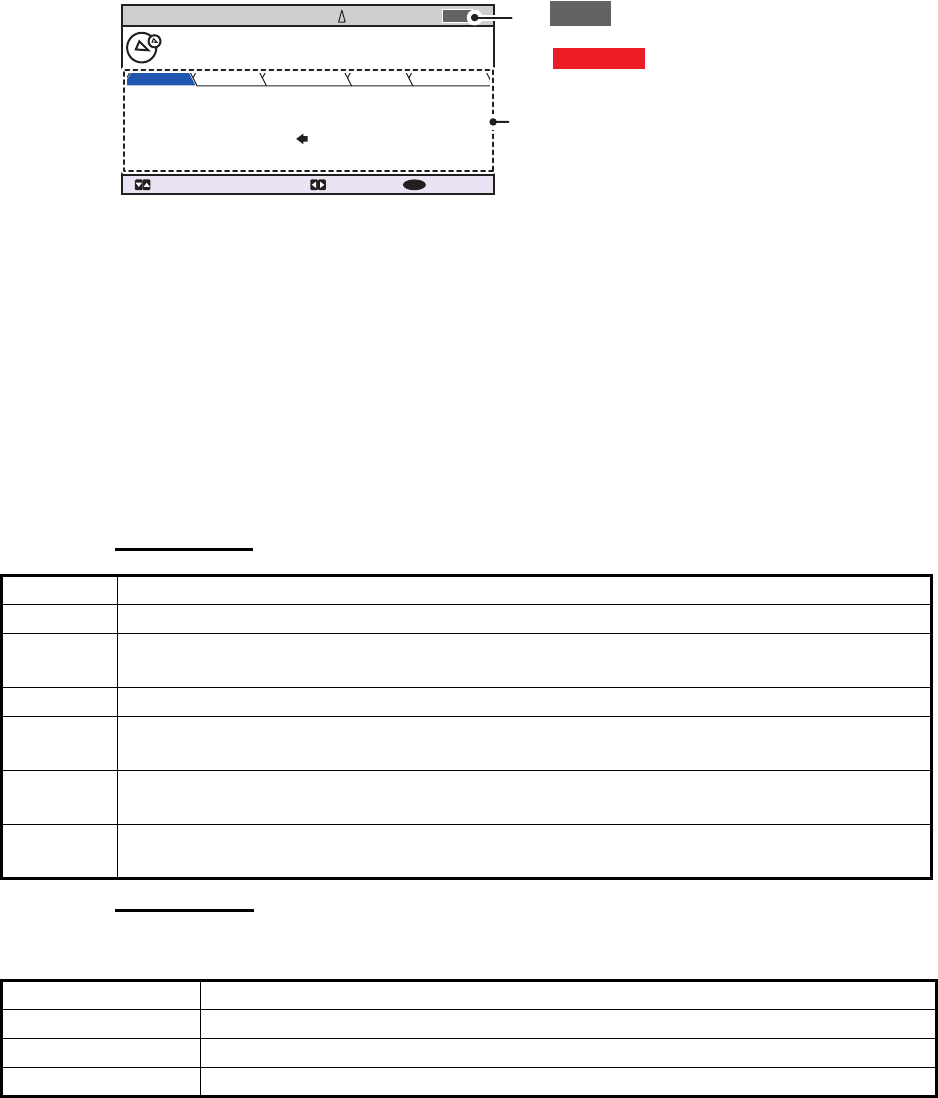
1.8.4 How to interpret the [TARGET DETAIL] screen
The [TARGET DETAIL] screen shows available detailed information about the select-
ed target.
Lost and dangerous targets have the appropriate icon displayed at the top right, as
indicated in the lost target example below.
There are five tabs available for viewing; [SENSOR], [VOYAGE], [IDENTITY],
[SCALE] and [QUALITY]. Press or to change the tab currently displayed.
The selected target’s bearing ([BRG]), range ([RNG]), [MMSI] and [NAME] are dis-
played at the top of the screen regardless of the selected tab. For lost or dangerous
targets, the appropriate icon is displayed at the top right of the screen.
The information displayed on each tab varies, depending on the type of target select-
ed.
The tables on the following pages list each tab’s contents, along with a brief descrip-
tion.
SENSOR tab
VOYAGE tab
The VOYAGE tab is only displayed for CLASS A target types.
Contents Description
POSN Target’s last known position. Displayed for all target types.
ROT Target’s Rate Of Turn. Displayed only for CLASS A, SART, MOB and EPIRB target
types.
ALT Altitude. Displayed only for SAR VESSEL and SAR AIRCRAFT target types.
SOG Target’s Speed Over Ground. Displayed only for CLASS A, CLASS B, SAR VESSEL,
SAR AIRCRAFT, SART, MOB and EPIB target types.
COG Target’s Course Over Ground. Displayed only for CLASS A, CLASS B, SAR VESSEL,
SAR AIRCRAFT, SART, MOB and EPIB target types.
HDG Target’s last known heading. Displayed only for CLASS A, CLASS B, SART, MOB and
EPIRB target types.
Contents Description
NAV STATUS Target’s navigational status (see section 1.6 for details).
DESTINATION Target’s destination.
ETA Target’s Estimated Time of Arrival at the above destination.
TARGET DETAIL
: TAB: TARGET : BACK
MENU
SENSOR VOYAGE IDENTITY SCALE QUALITY
CLASS A
FURUNOMARU
TYPE
34 º 44 .5000 ´N
130 .0º
135 .0º
135 º 21.3000 ´E
108 . 7 º/min ( )
10 .0 kn
POSN
HDG
COG
ROT
SOG
225.4º
3.02NM
BRG
RNG 201503030
NAME
MMSI
LOST
AThe LOST icon is displayed for
lost targets.
The DANGER icon is displayed
for dangerous targets.
When data input to the FA-170 is
interrupted or stopped, indications
for all tabs appear as “----”.

1. OPERATION
1-17
IDENTITY tab
The IDENTITY tab is only displayed for CLASS A, CLASS B, SAR VESSEL, SAR AIR-
CAFT and AtoN target types.
SCALE tab
The SCALE tab is only displayed for SAR VESSEL, SAR AIRCRAFT and AtoN target
types.
QUALITY tab
The QUALITY tab is displayed for all target types.
Contents Description
CALL SIGN Target’s call sign. Not displayed for AtoN target types.
IMO NO. Target’s International Maritime Organization registration number.
TYPE OF SHIP Target’s ship type. Displayed only for CLASS A and CLASS B target types.
REAL AtoN Displayed as "YES" for physical aids to navigation, "NO" for virtual aids to nav-
igation. Displayed only for AtoN target types.
TYPE OF AtoN The type of aids to navigation. Displayed only for AtoN target types.
VENDER ID Target’s AIS maker's ID. Displayed only for CLASS B target types.
Contents Description
SHIP SIZE(LENGTH, BEAM) Target’s ship size (length, beam). Displayed for all above target
types.
ANT POSN(X,Y) Position of target’s antenna. Displayed for all above target types.
DRAUGHT Target ship’s draught. Displayed only for CLASS A target types.
PI Off-position indicator. Displayed only for AtoN target types.
Contents Description
PA Position Accuracy for target ship. (HIGH: High accuracy, LOW: Low accuracy.)
RAIM Target’s RAIM status. (USED: Using RAIM, UNUSED: Not using RAIM.).
TIME STAMP Time at which the target was last detected. Not displayed for AIS base stations.
POSN
QUALITY
Target’s position quality. Possible position qualities are shown in the list below:
Quality indication Meaning
[NO POSITION] Position data not available.
[MANUAL POSITION] Position data is input manually.
[DEAD RECKONING POSITION] Position calculated by dead
reckoning.
[OUTDATED POSITION > 200 M] More than 200 m from last
estimated position.
[POSITION > 10 M] Difference of more than 10 m from last es-
timated position.
[POSITION WITH RAIM > 10 M] Difference of more than 10 m from last es-
timated position.
[POSITION < 10 M] Difference of less than 10 m from last esti-
mated position.
[POSITION WITH RAIM < 10 M] Difference of less than 10 m from last esti-
mated position.
[VALID POSN WITH NO TIME
STAMP]
No time stamp available.
1. OPERATION
1-18
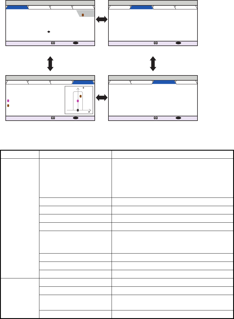
1.8.5 Own ship data
The [OWN INFORMATION] display shows your ship’s data across four tabs. The in-
formation displayed is shown in the figure below. This data should be checked once
per voyage or once per month whichever is shorter. Data may be changed only on the
authority of the master.
The Officer of the Watch should periodically check position, SOG and sensor informa-
tion for quality.
The table below list each tab’s contents along with a brief description.
Tab Item Description
[SENSOR] [UTC], [LT] Date and time.
[UTC]: Universal Time, Coordinated.
[LT]: Local time.
Note: For more information on these indica-
tions, see section 1.15.
[POSN] OS (Own Ship) position.
[ROT] Rate of Turn.
[SOG] Speed Over Ground.
[PA] Positioning accuracy.
[RAIM] RAIM status.
[USED]: RAIM is currently in use.
[UNUSED]: RAIM is not currently in use.
[HDG] Heading.
[COG] Course Over Ground.
GPS status GPS currently in use.
[VOYAGE] [NAV STATUS] Current navigational status.
[DESTINATION] Current destination.
[ETA [UTC]], [ETA [LT]] Estimate Time of Arrival (ETA) at the desti-
nation.
[NO. OF PERSONS] Number of people aboard your vessel.
OWN INFORMATION
: TAB : NEXT
DISP
SENSOR VOYAGE IDENTITY SCALE
UTC
12/NOV/2014 17 :20 :00
34 º 44 .5000 ´N
130 .0º
135 .0º
135 º 21.3000 ´E
108 . 7 º/min ( )
10 .0 kn
HIGH
UNUSED
POSN PA
RAIM
HDG
COG
ROT
SOG
OWN INFORMATION
: TAB : NEXT
DISP
SENSOR VOYAGE IDENTITY SCALE
NAV STATUS
DESTINATION
ETA (UTC)
NO. OF PERSONS
PWR-DRIVEN VESSEL PUSHING
AHEAD OR TOWING ALONGSIDE
KOBE
1850
10/MAY 10:51
12
OWN INFORMATION
: TAB : NEXT
DISP
SENSOR VOYAGE IDENTITY SCALE
MMSI
NAME
IMO NO.
CALL SIGN
TYPE OF SHIP
WIG
ARRYING DG, HS, OR, MP(OS)
24
@SEVEN@
FURUNOMARU
291 740 917
0123456789
OWN INFORMATION
: TAB : NEXT
DISP
120m 60m
0m60m
80m 15m
12 .3m
SENSOR VOYAGE IDENTITY SCALE
SHIP SIZE
LENGTH BEAM
ANT POSN Y X
X
Y
INTERNAL
1
2
EXTERNAL
DRAUGHT
2
1
0
SENSOR tab VOYAGE tab
IDENTITY tabSCALE tab
Press ► or ◄ to cycle
through the tabs.
EXTERNAL
DGPS
2

1. OPERATION
1-19
1.8.6 Alert display
The alert display shows the date and time alerts were generated. For further details,
see section 3.5.
[IDENTITY] [MMSI] Own Ship’s MMSI.
[NAME] Own Ship’s name.
[IMO NO.] Own Ship’s IMO number.
[CALL SIGN] Own Ship’s call sign.
[TYPE OF SHIP] Own Ship’s vessel type. See section 1.6,
step 7 for details.
[SCALE] [SHIP SIZE] Own Ship’s length and beam.
[ANT POSN] Antenna position.
[INTERNAL]: position of internal antenna.
[EXTERNAL]: position of external antenna.
[DRAUGHT] Own Ship’s draught.
Tab Item Description
1. OPERATION
1-20
1.9 Messages
You may send and receive messages via VHF channels, to a specified MMSI or all
AIS-equipped ships in the area. Messages can be sent to warn of safety of navigation;
for example, an iceberg sighted. Routine messages are also permitted.
Short safety-related messages are only an additional means to broadcast safety infor-
mation. They do not remove the requirements of the GMDSS.
When a message is received, the equipment beeps and pop up appears, indicating
the type of message received.
Sent messages are stored in the [MSG BOX] (message box) under the [OUTBOX] tab.
Received messages are stored in the [MSG BOX] under the [INBOX] tab.
The FA-170 can store up to 20 transmitted and up to 20 received messages. When
the [INBOX] or [OUTBOX] becomes full, the oldest message in the box is automatical-
ly deleted to make room for the latest.
1.9.1 How to send a message
This procedure applies to Class A AIS, for Inland AIS, see section 2.6.1.
1. Press the MENU/ESC key to open the main menu.
2. Select [MSG], then press the ENT/ACK key.
3. [NEW MSG] is selected. Press the ENT/ACK key. The [NEW MSG] screen ap-
pears.
4. [MSG TYPE] is selected, press the ENT/ACK key to change the type of message
you wish to send. The options pop up shown below appears.
5. Select the appropriate message type, then press the ENT/ACK key.
For broadcast messages, skip to step 8.
6. Select [TO], then press the ENT/ACK key. A numerical settings pop up appears.
7. Input the MMSI of the ship you wish to send this message to, then press the ENT/
ACK key to close the pop up. See section 1.5 for how to input data.
MSG
NEW MSG
MSG BOX
1
2
NEW MSG TEXT
( )
MSG TYPE
<SEND MSG>
: CURSOR
: SELECT
ADDRESSED
: BACK
ENT
MENU
:
TO 000000000
:
CH ALTERNATE
:
RETRY 3
:
TEXT
( 0 / 85 )
Use the software keyboard
to enter the message here.
:
MSG TYPE
BROADCAST
ADDRESSED
Message to all vessels.
Message to specified vessel only.
1. OPERATION
1-21
8. Select [CH] (Channel), then press the ENT/ACK key. The channel select options
pop up appears.
9. Select the appropriate option, then press the ENT/ACK key.
For broadcast messages, skip to step 12.
10. Select [RETRY], then press the ENT/ACK key. The retry attempts setting pop up
appears.
11. Press to increase the retry attempts, to decrease the retry attempts. The
maximum setting for retries is 3. Press the ENT/ACK key to apply the setting and
close the pop up.
12. Press to highlight the message text, then press the ENT/ACK to display the
software keyboard.
13. Input the new message text, referring to section 1.5.4. The maximum number of
characters allowed is as follows:
• BROADCAST: 90 characters.
• ADDRESSED: 85 characters.
14. Press or to highlight [<SEND MSG>] at the top right of the screen, then press
the ENT/ACK key. A confirmation pop up appears.
15. Select [YES] to send the message or [NO] to cancel the message, then press the
ENT/ACK key.
Note: The following pop up messages may be displayed during sending or after the
message has been sent.
Pop up message Description
MESSAGE SENT SUCCESSFULLY. Displayed after a message is sent successfully.
NO TEXT IN MESSAGE Displayed when the message body is blank and <SEND
MSG> is selected.
FAILED TO SEND MESSAGE.
(CODE:X)
The message failed to send. The code (indicated as "X"
in the example to the left) indicates the reason for the fail-
ure.
"CODE:1" indicates that the message was not acknowl-
edged by the recipient.
"CODE:2" indicates that the message failed to send.
CH
BOTH A & B
ONLY A
ONLY B
ALTERNATE
Sends the same message to both channel A and channel B.
Sends the message to channel A only.
Sends the message to channel B only.
Sends messages on alternating channels. In other words, if
the last message sent on channel A, the next message is
sent on channel B.
1. OPERATION
1-22
1.9.2 Receiving messages
When a message is received, the equipment beeps and a pop up message appears
on the screen. The table below lists the possible messages with a brief description. To
enable/disable these pop ups, see section 1.7.
1.9.3 How to use the message box (MSG BOX)
How to view a received message
To view message contents, follow the procedure below.
1. Press the ENT/ACK to close the pop up window.
2. Press the MENU/ESC key to show the main menu.
3. Select [MSG], then press the ENT/ACK key.
4. Select [MSG BOX], then press the ENT/ACK key. The [OUTBOX] tab is displayed
by default. Press to display the [INBOX] tab.
5. Select the message you wish to view, then press the ENT/ACK key. The message
options pop up window shown below appears.
Select [VIEW DETAIL], then press the ENT/ACK key to display the received mes-
sage’s contents. The figure above shows an example of a received message.
Select [NEW MSG], then press the ENT/ACK key to send a message back to this
message’s sender.
6. Press or to view other messages, press or to switch between viewing
an [INBOX] message and an [OUTBOX] message.
7. Press the DISP key to close the menu.
Pop up message Description
TEXT MESSAGE RECEIVED. Displayed when a broadcast message is received.
TEXT MESSAGE RECEIVED.
MMSI/NAME.
Displayed when an addressed message is received.
MMSI appears by default, however, where name data is
available, the vessel name is also displayed.
MSG BOX TEXT
( )
INBOX: 12
OUTBOX: 10
TIME [UTC]
30 /MAY 17 : 20 BROADCAST
BROADCAST
ENTERPRISE
BROADCAST
NEPTUNE
BROADCAST
NAUTILUS
29 /MAY 16 :05
28 /MAY 16 :15
27 /MAY 17 :20
26 /MAY 17 :20
25 /MAY 17 :20
24 /MAY 17 :20
FROM 01 / 10
: CURSOR
: FUNC
ENT
: TAB
: BACK
MENU
Indication Meaning
This message has been viewed.
This message is unviewed.
Broadcast message
Addressed message
FUNCTION
VIEW DETAIL
NEW MSG
MENU
INBOX MSG DETAIL ( TEXT )
MSG TYPE ADDRESSED
28 / MAY 16 : 15
987654321 / ENTERPRISE
KLINGONS ON STBD BOW.
TIME [UTC]
TO
TEXT
( 21)
: BACK: BOX: MESSAGE
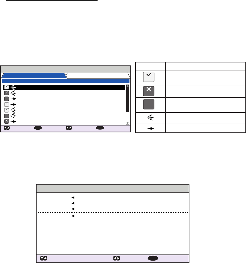
1. OPERATION
1-23
How to view sent messages
1. Press the ENT/ACK to close the pop up window.
2. Press the MENU/ESC key to show the main menu.
3. Select [MSG], then press the ENT/ACK key.
4. Select [MSG BOX], then press the ENT/ACK key. The [OUTBOX] tab is displayed
by default.
5. To view the contents of a message, highlight the message then press the ENT/
ACK key. The message options pop up window appears.
Select [VIEW DETAIL] to display the received message’s contents. The figure be-
low shows an example of a received message.
Select [NEW MSG] to send another message to the recipient.
6. Press or to view other messages, press or to switch between viewing
an [INBOX] message and an [OUTBOX] message.
7. Press the DISP key to close the menu.
MSG BOX ( TEXT )
INBOX: 12
OUTBOX: 10
TIME [UTC]
30 /MAY 18 : 25
BROADCAST
BROADCAST
TITANIC
NAUTILUS
BROADCAST
BROADCAST
MUSASHIMARU
29 /MAY 16 :05
28 /MAY 16 :15
27 /MAY 17 :20
26 /MAY 17 :20
25 /MAY 17 :20
24 /MAY 17 :20
TO 01 / 10
: CURSOR
: FUNC
ENT
: TAB
: BACK
MENU
Indication Meaning
This message was sent
successfully.
This message was not sent.
Waiting for recipient to
acknowledged this message.
Broadcast message
Addressed message
NO
ACK
NO
ACK
OK
OK
OK
OK
NG
NG
NO
ACK
NG
MENU
OUTBOX MSG DETAIL ( TEXT )
MSG TYPE ADDRESSED
28 / MAY 16 : 15
123456789 / TITANIC
ICEBERG COORDINATES RECEIVED.
THANK YOU!
TIME [UTC]
TO
TEXT
( 39 / 85)
: BACK: BOX: MESSAGE

1. OPERATION
1-24
1.10 Regional Operating Channels
AIS operates primarily on two dedicated VHF channels, CH 2087 and CH2088. Where
these channels are not available regionally, the AIS is capable of being automatically
switched to designated alternate channels by means of a message from a shore facil-
ity. Where no shore based AIS or GMDSS sea area A1 station is in place, the AIS
should be switched manually as in paragraph 1.10.2.
A regional operating area is set with the procedure shown below. The most recent
eight areas are memorized.
• Automatic setting of VHF DSC (channel 70) from shore-based AIS.
• Automatic setting by AIS message from shore-based AIS.
• Setting by shipboard system such as ECDIS.
• Manual setting
The default area is as follows:
• Tx power: 12.5 W
• Channel no. 2087, 2088
• Tx/Rx mode: Tx/Rx
1.10.1 How to view channel information
Do the following to view current channel information. To edit channel information, see
paragraph 1.10.2.
1. Press the MENU/ESC key to open the menu.
2. Select [CH INFO]. The [CH INFO] pop up window appears.
3. Press the DISP key to close the display.
CH INFO
REGION LIST
PWR
CH A
CH B
TX / RX A
TX /RX B
HIGH
2087
2088
TXRX
TX
1
Select to display the regional
channel list.
PWR
C
H A
C
H B
TX
/
RX A
TX
/
RX
B
H
IG
H
208
7
2088
T
XR
X
TX
Current channel’s details.
PWR: Power.
CH A: Channel used for channel A.
CH B: Channel used for channel B.
TX / RX A: Channel A TX/RX
settings.
TX / RX B: Channel B TX/RX
settings.
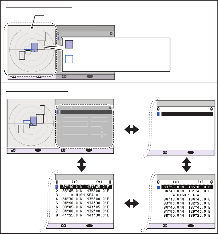
1. OPERATION
1-25
1.10.2 How to edit/view regional channels
You may display the status of regional operating areas currently memorized in the
equipment. Nine of any combination of AIS message from shore-based AIS, DSC
message, manual settings and commands from ECDIS or a PC may be registered and
one will be [HIGH SEA].
• AIS and DSC messages registered within last two hours cannot be edited.
• An item labeled [HIGH SEA] cannot be edited. ([HIGH SEA] are data used for inter-
national waters not controlled by shore-based AIS.)
• If two areas overlap one another the older data is deleted.
• Data older than 24 hours is deleted.
• Area data is deleted when it is more than 500 miles from the area for which it was
registered.
1. Press the MENU/ESC key to open the menu.
2. Select [CH INFO], then press the ENT/ACK key.
3. Select [REGION LIST] then press the ENT/ACK key. The REGION LIST has four
pages of data related to each region, displayed on the left-side of the screen as
shown in the figure below. The right side of the screen displays your current posi-
tion, current region and the selected region.
Press or to change pages.
34º 44. 5´N / 135º21. 3´ E
500
NM
REGION LIST
PWR CH A CH B
CURSOR
: EDIT : DATA
ENT
: BACK
MENU
1
H 2087 / TXRX 2088 / RX
H 2087 / TXRX 2088 / RX
H 2087 / TXRX 2088 / RX
L 1111 / TXRX 2222 / OFF
H 3333 / TXRX 4444 /
TXRX
L 3087 / TXRX 3088 /
RX
L 3087 / TXRX 3088 /
RX
L 3087 / TXRX
= NO ENTRY =
3088 / OFF
2:
:
:
:
:
:
:
:
:
3
4
5
6
7
8
9
REGION LIST
AGE FROM
1
1 : 59
MMSI : 123456789
MMSI : 123456789
MMSI : 987654321
11 : 59
MANUAL INPUT
= HIGH SEA =
23 : 59
MANUAL INPUT
19 : 59
12 : 00
MMSI : 987654321
23 : 59
MMSI : 987654321
23 : 59
= NO ENTRY =
2:
:
:
:
:
:
:
:
:
3
4
5
6
7
8
9
PWR
CH A
C
H B
1
H 2087
/
TXR
X
2088
/
RX
H 2087 / TXR
X
2088 / RX
H 2
08
7
/
TXR
X
2
088
/
RX
L
1111 / TXR
X
2222 /
O
F
F
H
3333
/ TXR
X
4
444 /
TXR
X
L
308
7 / TXR
X
3088
/
RX
L
308
7 / TXR
X
3088
/
RX
L
308
7 / TXR
X
= N
O
ENTRY
=
3088
/
O
F
F
2
:
:
:
:
:
:
:
:
:
3
4
5
6
7
8
9
: DATA : BACK
MENU
REGION LIST
: DATA : BACK
MENU
= NO ENTRY =
:
9
LAT LON
REGION LIST
: DATA : BACK
MENU
= NO ENTRY =
:9
LAT LON
34º 44. 5´N / 135º21. 3´ E
500
NM
REGION LIST
PWR CH A CH B
CURSOR
: EDIT : DATA
ENT
: BACK
MENU
1
H 2087 / TXRX 2088 / RX
H 2087 / TXRX 2088 / RX
H 2087 / TXRX 2088 / RX
L 1111 / TXRX 2222 / OFF
H 3333 / TXRX 4444 /
TXRX
L 3087 / TXRX 3088 /
RX
L 3087 / TXRX 3088 /
RX
L 3087 / TXRX
= NO ENTRY =
3088 / OFF
2:
:
:
:
:
:
:
:
:
3
4
5
6
7
8
9
R
EGION LIS
T
PWR
C
H A
C
H B
:
DATA
:
BA
CK
M
EN
U
1
H 2
08
7
/
TXR
X
2088
/
RX
H 2
08
7
/
TXR
X
2088
/
RX
H 2
08
7
/
TXR
X
2088
/
RX
L
1111
/
TXR
X
2
222 /
O
F
F
H
3333
/
TXR
X
4444
/
TXRX
L
3087
/
TXR
X
3088
/
RX
L
3087
/
TXR
X
3088
/
RX
L
3087
/
TXR
X
=
N
O
ENTRY =
3088 / OF
F
2
:
:
:
:
:
:
:
:
:
3
4
5
6
7
8
9
: Region your vessel is currently in.
(Blue-shaded square)
: Region selected in the [REGION LIST].
(Square is highlighted in blue)
Own Ship’s current position.
Right-side of the screen
Left-side of the screen
1
2:
:
:
:
:
:
:
:
3
4
5
6
7
8
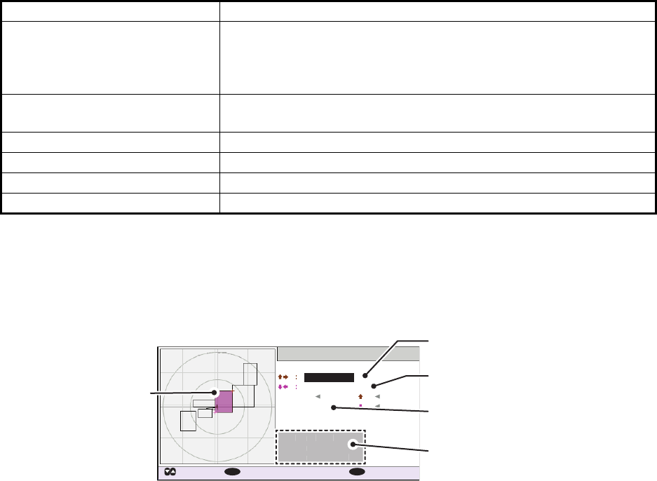
1. OPERATION
1-26
The data displayed on each page of the [REGION LIST] is described in the table
below.
4. Select the desired region number. You can select a region to edit from any page
in the [REGION LIST]. The selected region is highlighted in blue on the plotter
screen.
5. Press the ENT/ACK key to show the selected region’s details. The region is high-
lighted in light red on the plotter screen, as shown in the figure below.
6. The [LAT] setting for the top-right corner of the region is already selected; press
the ENT/ACK key. Input the latitude for the top-right position (northeast point) of
the AIS operating area then press the ENT/ACK key.
7. Press to select the [LON] setting for the top-right corner, then press the ENT/
ACK key. Input the longitude for the right-top position (northeast point) of the AIS
operating area then press the ENT/ACK key.
8. Press to select the [LAT] setting for the bottom-left corner, then press the ENT/
ACK key. Enter latitude for the bottom-left position (southwest point) of the AIS
operating area then press the ENT/ACK key.
9. Press to select the [LON] setting for the bottom-left corner, then press the ENT/
ACK key. Enter longitude for the bottom-left position (southwest point) of the AIS
operating area then press the ENT/ACK key.
Note: The overall area for the selected region in displayed in height (H) and width
(H) values, in gray text. If the set region less than 20 nautical or more than 200
nautical miles long/wide, the height and width values are displayed in red text.
Adjust the dimensions so the length/width of the region is more than 20 nautical
miles and less than 200 nautical miles.
Data Description
Region number Up to eight regions can be assigned and set up. The ninth region
is reserved for open seas and is displayed as "= HIGH SEA =".
The region you are currently in is highlighted in blue (no. 1 in the
example on the previous page).
PWR • H: High power TX setting.
• L: Low power TX setting.
CH A/CH B Channel A/B’s frequency and TX/RX settings.
AGE Time since the channel was registered.
FROM Cause/origin of the last change.
LAT/LON Latitude and Longitude of the region’s corners.
EDIT REGION
[AREA]
37º 10 .0 ´N
33º 50 .0 ´N
H 200NM
131NM
W
137º 45 .0 ´E
135º 00 .0 ´E
[CH]
ZONE
<SAVE>
3NM
PWR
CH A
CH B
HIGH
2087 / TXRX
2088 / RX
:
:
:
:
LAT LON
: CURSOR
: SELECT
137NM
W
ENT
: BACK
MENU
34º 44. 5´N / 135º21. 3´ E
500NM
Selected region is
highlighted in light
red color.
Coordinates for the top-right
corner of the region.
Coordinates for the bottom-left
corner of region.
Transition zone setting.
(1 to 8 NM)
Region channel settings.
[
CH
]
PWR
C
H
A
CH
B
HI
GH
2
08
7
/
TXR
X
208
8 /
RX
:
:
:
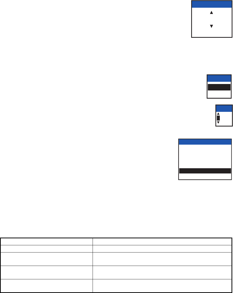
1. OPERATION
1-27
10. Press to select the setting for [ZONE], then press the ENT/
ACK key. A numerical input pop up window appears. The
transition zone works as a buffer between your current region
and the regions immediately adjacent to your current region.
When any vessel enters the transition zone, messages sent
from the adjacent region channel A are received via your re-
gion’s channel B. This helps to locate vessels in adjacent re-
gions.
11. Input the size of the transition zone for this region, then press the ENT/ACK key.
12. Press to select [PWR], then press the ENT/ACK key to show the
channel power options.
13. Select [HIGH] or [LOW] power desired then press the ENT/ACK key.
14. Select the channel indication for [CH A], then press the ENT/ACK key. A
numerical input pop up window appears.
15. Input the channel number for [CH A] then press the ENT/ACK key.
16. Press to select the transmit/receive settings, then press
the ENT/ACK key. An options pop up window appears.
17. Select the appropriate setting, then press the ENT/ACK
key.
[TXRX]: Transmit and receive.
[RX]: Receive only.
[OFF]: Disable the channel.
18. Press to select [<SAVE>], then press the ENT/ACK key. A confirmation pop up
window appears.
Select [YES] to apply the new settings and return to the [REGION LIST], [NO] to
cancel the new settings and return to editing the region.
Note: If you enter invalid data, a pop up message stating the reason for the error
appears. The table on the following page lists the pop up messages for these er-
rors and the recommended action for each error.
Pop up error message Recommended action
INVALID CHANNEL Check the channel setting, re-input the settings.
INVALID REGION SIZE. Check the region size is less than 200 NM and more than
20 NM. Adjust your region size.
INVALID REGION. ADJUST SIZE OR
LOCATION.
Check your region size and location, there is at least one
other region overlapping. Resize or relocate your region.
INVALID OPERATION: REGION
CANNOT BE OVERWRITTEN.
Check the overlapping regions.
Adjust your region size or location.
TRANS ZONE
5
[ 1, 8 ]
PWR
HIGH
LOW
CH A
2087
TX/RX A & B
A : TXRX / B : TXRX
A : TXRX / B : RX
A : RX / B : TXRX
A : RX / B : RX
A : RX / B : OFF
A : OFF / B : RX
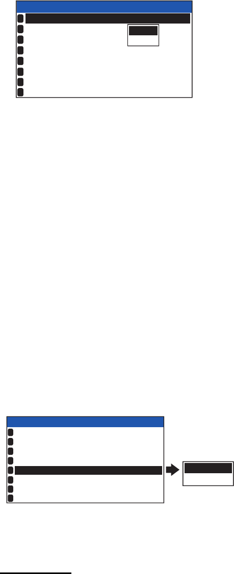
1. OPERATION
1-28
1.11 How to Enable/Disable the Key Beep
You can turn off the beep, which sounds for valid key input.
1. Press the MENU/ESC key to open the menu.
2. Select [USER SET], then press the ENT/ACK key.
3. [KEY BEEP] is already selected, press the ENT/ACK key.
4. Select [ON] or [OFF] as appropriate then press the ENT/ACK key.
5. Press the DISP key to close the menu.
1.12 Long Range
The long range function sets how to reply to a request for own ship data from a distant
station (for example, an Inmarsat C station) and whether to transmit your ship's posi-
tion to a satellite via the AIS VHF communication link or not.
1.12.1 How to set up long range response
The long range response sets how to reply to a request for own ship data from a dis-
tant station, for example, an Inmarsat C station. You may reply automatically or man-
ually.
1. Press the MENU/ESC key to open the menu.
2. Select [USER SET], then press the ENT/ACK key.
3. Select [LR RESPONSE] then press the ENT/ACK key. The options pop up win-
dow appears.
4. Select [AUTO] (auto reply) or [MANUAL] (manual reply) as appropriate then press
the ENT/ACK key.
5. Press the DISP key to close the menu.
Manual reply
For manual reply, the requesting ship's MMSI, name and information requested ap-
pear.Select [REFUSE], then press the ENT/ACK key to send no data, or select [RE-
PLY], then press the ENT/ACK to send data. The screen then changes according to
your selection.w
ON
OFF
USER SET
ON
HIDE
AUTO
ON
KEY BEEP
TIME DIFF
AUTO SORT
SART TEST
LR RESPONSE
LR BROADCAST
1
2
3
4
5
6
NOTIFICATION SET
7
ACTIVATE
8
:
:
:
:
AUTO
MANUAL
USER SET
ON
HIDE
AUTO
ON
KEY BEEP
TIME DIFF
AUTO SORT
SART TEST
LR RESPONSE
LR BROADCAST
1
2
3
4
5
6
NOTIFICATION SET
7
ACTIVATE
8
:
+00 : 00
:
:
:
:
ON
:
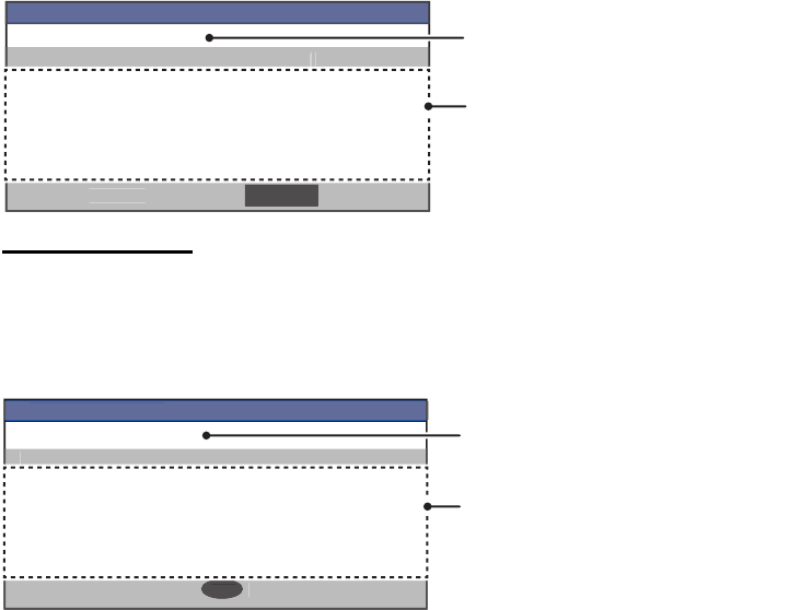
1. OPERATION
1-29
Automatic reply
For automatic reply, the pop up message shown below appears when an automatic
reply is sent. Requested data is automatically transmitted. Press the ENT/ACK key to
close the message.
1.12.2 How to broadcast own ship data
You can broadcast own ship data to a satellite via the AIS VHF communication link.
1. Press the MENU/ESC key to open the menu.
2. Select [USER SET] then press the ENT/ACK key.
3. Select [LR BROADCAST] then press the ENT/ACK key.
4. Select [ON] or [OFF] as appropriate then press the ENT/ACK key.
[ON] sends your ship's position to a satellite via the AIS VHF communication link.
5. Press the DISP key to close the menu.
Note: The availability of this function depends of equipment specifications. The menu
is not shown unless so equipped.
INFORMATION
NAME: HMSS TITANIC
[LONG RANGE REQUEST DETAILS]
NAME/CALL SIGN/IMO NO.
DESTINATION
POSN
LENGTH/BEAM
COG
SOG DRAUGHT
TYPE OF SHIP
NO. OF PERSONS
DATE TIME
REFUSEREPLY
Information requested by the long
range station is displayed here.
Name of requesting station or
vessel.
[
LO
N
G
RAN
G
E RE
Q
UE
S
T DETAIL
S
]
INF
O
RMATI
ON
R
EFUSE
REP
L
Y
INFORMATION
NAME: HMSS TITANIC
[LONG RANGE RESPONSE DETAILS]
NAME/CALL SIGN/IMO NO.
DESTINATION
POSN
LENGTH/BEAM
COG
SOG DRAUGHT
TYPE OF SHIP
NO. OF PERSONS
DATE TIME
: CLOSE WINDOW
ENT
Information sent to the long
range station is displayed here.
[
LO
N
G
RAN
G
E RE
S
P
O
N
S
E DETAIL
S
]
INF
O
RMATI
ON
:
CLOSE WINDO
W
ENT
Name of requesting station or
vessel.
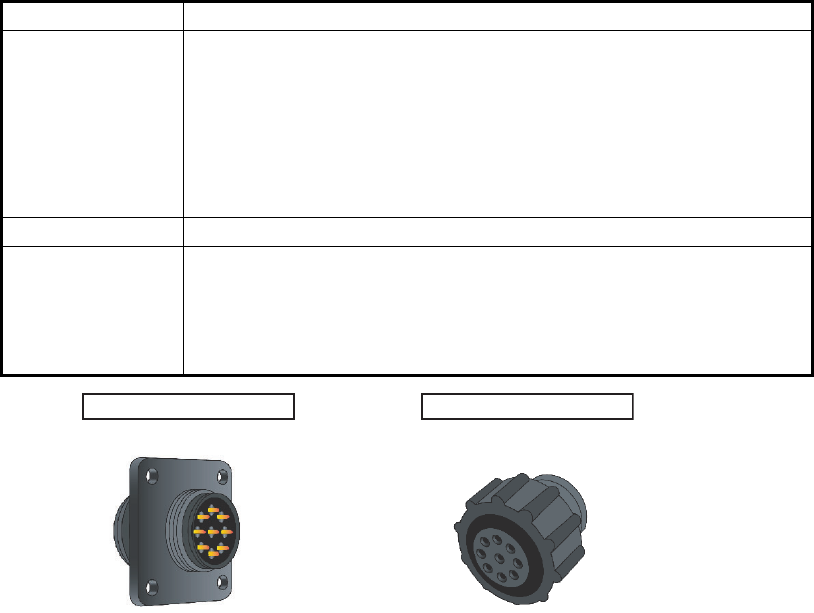
1. OPERATION
1-30
1.13 Pilot Plug (FA-1703, option)
A pilot plug, which is connected between the AIS and a PC, is required to feed AIS
information to a PC. The plug is required for the ships passing through the Panama
Canal and the Saint Lawrence Seaway. The specifications for the pilot plug are as
shown below.
Pilot Plug connectors for FA-1703
Item Specifications
Baud rate 38400 bps
Note: The following setting is required for the FA-170. If the pilot
does not function, check these the following items.
• COM port settings: [INITIAL SET] menu [I/O PORT]. The se-
lected port for the pilot plug must be set to [EXT DISPLAY].
• Check the pilot plug connection at both the FA-170 and the con-
nected PC.
Type AMP 206486-1 (9-pin, male)
Signal
connection
TX-A: Pin 1
TX-B: Pin 4
RX-A: Pin 5
RX-B: Pin 6
SHIELD: Pin 9
Connector for AIS Connector for PC
206486-1 206485-1
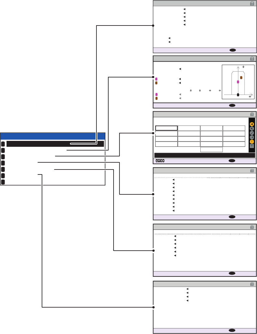
1. OPERATION
1-31
1.14 Viewing Initial Settings
The [INITIAL SET] menu, which is locked with a password to prevent accidental
changes to the ship’s details, is where the installer enters ship’s MMSI, internal and
external antenna positions, ship type, I/O port settings and network settings. You can
view the settings on this menu as follows.
1. Press the MENU/ESC to open the menu.
2. Select [INITIAL SET], then Press the ENT/ACK key.
3. Select item to view then press the ENT/ACK key.
4. Press the DISP key to close the menu.
ANTENNA POSITION
: BACK
MENU
120m 60m
60m
80m
X
Y
2
1
0
[SHIP SIZE ] LENGTH BEAM
[ANT POSN] Y X
[ANT POSN]
A , B C , D
INTERNAL
EXTERNAL
INTERNAL
60 , 60
40 , 80
30 , 30
45 , 15
EXTERNAL
1
2
1
2
0m
15m
ALERT ENABLE
: BACK
: CURSOR
MENU
WARNING1
ENABLE
001 014
026
030
029
005
007
009
010
008
011
025
035
032
002
003
004
DISABLE
ENABLE
HI
LO
001 :
TX MALFUNCTION
DISABLE
WARNING2
: 8 : 0 : 0: 10
PORT
COM1
38400baud
38400baud
38400baud
38400baud
38400baud
38400baud
4800baud
4800baud
4800baud
COM2
COM3
COM4
COM5
COM6
SENSOR1
SENSOR2
SENSOR3 SENSOR
SENSOR
SENSOR
EXT
DISPLAY
EXT
DISPLAY
EXT
DISPLAY
EXT
DISPLAY
EXT
DISPLAY
LONG RANGE
MODE
SPEED
I / O PORT
: BACK
MENU
LOCK
SHIP’S INFORMATION
ANTENNA POSITION
ALERT ENABLE
I / O PORT
PORT PRIORITY
NETWORK
EDIT :
INITIAL SET
1
2
3
4
5
6
7
PRIORITY
LL /
SOG
/
COG
HDG
ROT
2nd
1st
3rd
4th
5th
6th
SENSOR1
SENSOR3 SENSOR3
SENSOR1 SENSOR1
SENSOR2 SENSOR2
SENSOR2
SENSOR3
COM4 COM6
COM4
COM5
COM6
COM4
COM5
COM5
COM6
PORT PRIORITY
: BACK
MENU
IP
ADDRESS
172 . 031 . 024 . 004
255 . 255 . 000 . 000
000 . 000 . 000 . 000
SUBNET MASK
GATEWAY
AI0001
SFI
NETWORK
: BACK
MENU
SHIP’S INFORMATION
MMSI 234567891
PERSEPHONE
987654321
@SEVEN@
NAME
IMO NO.
CALL SIGN
CH C 0075
CH D 0076
[LONG RANGE]
: BACK
MENU
24 (WIG)
TYPE OF SHIP
CARRYING DG, HS, OR, MP(OS)
Note: The availability of some
functions depends on the
equipment specifications of your
vessel. Some items are not
displayed unless the vessel is
equipped accordingly.
Password access is required to
change these settings. Contact
your local dealer to change the
settings if required.
Displayed as “NETWORK (NAVNET)”
when the network type is set to [NAVNET].
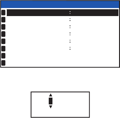
1. OPERATION
1-32
1.15 Setting for Time Difference
You can set the time differences from UTC (Coordinated Universal Time) to show the
local time.
1. Press the MENU/ESC key to open the menu.
2. Select [USER SET] then press the ENT/ACK key.
3. Select [TIME DIFF], then press the ENT/ACK key. The settings pop up window is
displayed.
4. Select the desired time difference then press the ENT/ACK key. You can change
the value with or , the digit with or The setting range is -14:00 to +14:00.
5. Press the DISP key to close the menu.
Note: When a UTC time offset is set, the time display indication for messages and
NAV STATUS screen is indicated as "LT" (Local Time). When there is no offset, the
time display indication for messages and the NAV STATUS screen is indicated as
"UTC" (Coordinated Universal Time).
USER SET
KEY BEEP
AUTO SORT
TIME DIFF
ON
HIDE
AUTO
+00 : 00
ON
SART TEST
LR RESPONSE
LR BROADCAST
NOTIFICATION SET
ACTIVATE
1
2
3
4
5
6
7
8
ON
+ 00:00
[ -14 : 00 , 14 : 00 ]

2-1
2. INLAND AIS OPERATION
This section provides the operating procedures for the Inland AIS feature, which al-
lows use of the AIS transponder on inland waterways or the open sea. Only those pro-
cedures that are different from the Class A AIS transponder are presented.
Ships with Inland AIS transponders on board autonomously determine their actual po-
sition using the Global Positioning System (GPS), which is part of the AIS transpon-
der. Furthermore they broadcast their ID and position to other ships over a distance of
10 to 30 kilometers (depending on the geographical environment). Other ships in the
area receive this information and are able to display their own position and that of oth-
er ships. Inland AIS helps the skipper in his direct nautical decisions, especially in crit-
ical situations, like the approach of a bend or a constriction.
Further, authorities have the possibility to allow electronic submission of cargo lists
e.g. for transports of dangerous cargo. The standard for “Electronic Reporting” (ERI)
allows the digital, language independent submission of cargo or passenger reports
from ships or agencies to authorities. In combination with electronic data exchange
between the authorities of different countries this results in less reporting for the skip-
pers. On the other hand all cargo information is available to authorities in case of an
accident.
2.1 How to Activate the Inland AIS
Input your key number (received from dealer) to activate the Inland AIS. (If the key was
input during the installation, activation key input is not necessary.)
1. Press the MENU/ESC key to open the menu.
2. Select [USER SET] then press the ENT/ACK key.
3. Select [ACTIVATE] then press the ENT/ACK key.
4. Press the ENT/ACK key to display the alphanumeric pop up window.The selected
digit cycles through digits in the following order when is pressed: 1, 2 ... 9, 0,
A, B, C ... X, Y, Z, 1, 2... press to cycle through digits in the opposite direction.
Press or to move the selection cursor.
5. Input the activation key, then press the ENT/ACK key.
If you entered the activation key correctly, the indication "ACTIVATED!" appears then
the system is automatically restarted. The FA-170 starts up with the SOLAS mode ac-
tive.
DEVICE ID
AB-12-C3-ZD-AA-N4
_ _-_ _-_ _-_ _-_ _-_ _
INACTIVATED
:
ACTIVATE KEY
ACTIVATE
: BACK
: SELECT
MENU
ENT
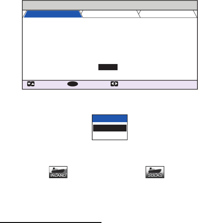
2. INLAND AIS OPERATION
2-2
2.2 Selecting AIS Mode
The Inland AIS has two operating modes: Inland (inland waterways) and SOLAS (SO-
LAS compliant class A AIS transponder). Select desired mode as follows:
1. Press the NAV STATUS key to open the [NAV STATUS] menu.
2. Press to select [AIS MODE] then press the ENT/ACK key. The mode selection
pop up window appears.
3. Select [SOLAS] or [INLAND] as appropriate then press the ENT/ACK key. The
AIS mode icon at the top of the screen changes to display the selected mode.
You are asked if you are sure to reboot the system. Select [YES] then press the ENT/
ACK key to reboot the unit.
Notes on Inland AIS operation
• IMO NO. is transmitted with all zeros.
• The draught used in Inland AIS is “Inland draught”.
NAV STATUS
: TAB
: SELECT:
CURSOR
ENT
VOYAGE
SHIP’S
INFO
SCALE
NAV STATUS
DESTINATION
ETA (UTC)
AIS MODE
DYNAMIC INFO RATE
PWR-DRIVEN VESSEL PUSHING
AHEAD OR TOWING ALONGSIDE
KOBE
[SOLAS LIST ]
SOLAS
AUTO
[INLAND LIST ]
10 / MAY 10 : 51
12
:
:
:
:
:
AIS MODE
SOLAS
INLAND
Inland mode active SOLAS mode active
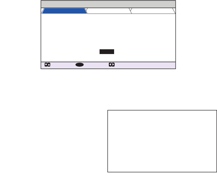
2. INLAND AIS OPERATION
2-3
2.3 How to Enter Voyage-Related Data
Before you embark on a voyage using Inland AIS, set the various related data (see the
list below) on the [NAV STATUS] menu.
1. Press the NAV STATUS key.
The [NAV STATUS] setting is selected by default.
2. If your navigational status is different from that shown, follow the procedure below.
If it is the same as shown, go to step 3.
1) Press the ENT/ACK key. The [NAV STATUS] options pop up window appears.
2) Input the appropriate status, then press the ENT/ACK key. Refer to the data
below to select appropriate navigational status.
3. Select [DESTINATION], then press the ENT/ACK key. The software keyboard ap-
pears for direct input. See section 1.5.4 for how to use the software keyboard.
Enter the desired destination then press the ENT/ACK key. You can use up to 20
alphanumeric characters and enter up to 20 destinations.
• Navigational status
• Destination
• Arrival time
• AIS mode currently in use
• Rate at which your vessel’s dynamic
information is transmitted
• ERI code
• No. of blue cones (for hazardous cargo)
• Cargo status
• No. of persons
• Length and beam of ship
• Draught
NAV STATUS
: TAB
: SELECT:
CURSOR
ENT
VOYAGE
SHIP’S
INFO
SCALE
NAV STATUS
DESTINATION
ETA (UTC)
AIS MODE
DYNAMIC INFO RATE
PWR-DRIVEN VESSEL PUSHING
AHEAD OR TOWING ALONGSIDE
KOBE
[SOLAS LIST ]
SOLAS
AUTO
[INLAND LIST ]
10 / MAY 10 : 51
12
:
:
:
:
:
00: UNDERWAY USING ENGINE
01: AT ANCHOR
02: NOT UNDER COMMAND
03: RESTRICTED MANEUVERABILITY
04: CONSTRAINED BY HER DRAUGHT
05: MOORED
06: AGROUND
07: ENGAGED IN FISHING
08: UNDERWAY SAILING
09: RESERVED FOR HIGH SPEED CRAFT (HSC)*
1
10: RESERVED FOR WING IN GROUND (WIG)*
2
11: PWR-DRIVEN VESSEL TOWING ASTERN
12: PWR-DRIVEN VESSEL PUSHING AHEAD OR TOWING ALONGSIDE
13: RESERVED FOR FUTURE USE
14: AIS-SART (ACTIVE), MOB-AIS, EPIRB-AIS*
3
15: DEFAULT (ALSO USED BY SART, MOB, EPIRB UNDER TEST)
*1: RESERVED FOR FUTURE AMENDMENT OF
NAVIGATIONAL STATUS FOR SHIPS CARRYING DG, HS,
OR MP, OR IMO HAZARD OR POLLUTANT CATEGORY C,
HIGH SPEED CRAFT (HSC)
*2: RESERVED FOR FUTURE AMENDMENT OF
NAVIGATIONAL STATUS FOR SHIPS CARRYING
DANGEROUS GOODS (DG), HARMFUL SUBSTANCES
(HS) OR MARINE POLLUTANTS (MP), OR IMO HAZARD
OR POLLUTANT CATEGORY A, WING IN GRAND (WIG)
*3: Not selectable.
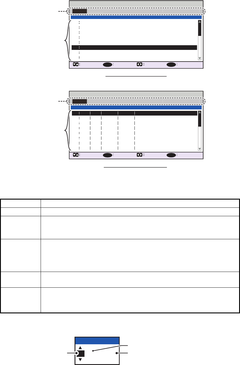
2. INLAND AIS OPERATION
2-4
A list of destinations can also be accessed by selecting [SOLAS LIST] (displayed
as DESTINATION LIST once accessed, as shown in the figure below) or [INLAND
LIST] as appropriate for your AIS mode.
Referring to operation descriptions in the table below, press or to select an
operation, press or to select an entry in the list, then press the ENT/ACK key
to confirm the selection.
4. Select [ETA (LT/UTC)], then press the ENT/ACK key. The settings pop up window
shown below appears.
Note 1: The ETA indication appears as "ETA [UTC]" when there a time offset is
set from [TIME DIFF] in the [USER SET] menu. When the setting for [TIME DIFF]
Operation Description
<SET> Set the currently selection as the destination.
<EDIT> Rename the selected destination. The software keyboard appears when
<EDIT> is selected. See section 1.5.4 for how to use the software key-
board.
<CUT> Cut the current selection to temporary memory, leaving the entry empty.
The destination can now be pasted as a different entry.
Note: Only one entry can be stored in temporary memory at a time. If
you <CUT> two entries successively, the first is deleted.
<COPY> Copy the current selection to temporary memory. The destination can
now be pasted as a different entry.
<PASTE> Paste the entry stored in temporary memory to the selected destination
number.
Note: Entries over-written with <PASTE> cannot be restored.
INLAND DESTINATION LIST
<EDIT>
DE TRI 01234 11111 56789
00000 00000
00000 00000
00000 00000
00000 00000
00000 00000
00000 00000
00000 00000
07
06
05
04
03
02
01
08
INLAND DESTINATION
<COPY>
CURSOR
EXEC FUNC
BACK
<PASTE>
<CUT>
<SET>
01 / 20
ENT
MENU
07
06
08
<EDIT>
05
04
03
02
01
<COPY>
CURSOR
EXEC FUNC
BACK
<PASTE>
<CUT>
<SET>
ENT
MENU
DESTINATION LIST
KOBE
OSAKA
TOKYO
YOKOHAMA
KAWASAKI
= NO ENTRY =
= NO ENTRY =
05
04
03
02
01 / 20
DESTINATION
ABERDEEN
CURSOR
EXEC FUNC
BACK
SOLAS destinations list
INLAND destinations list
Operation selection bar
<
EDIT
>
<COPY
>
<
PASTE>
<CUT
>
<SET
>
Destinations
Operation selection bar
<
EDIT
>
<COPY
>
<
PASTE>
<CUT
>
<SET
>
DESTINATION
Destinations
12 / 10 12:32
ETA (UTC)
ETA month
ETA day ETA time
in 24hr format
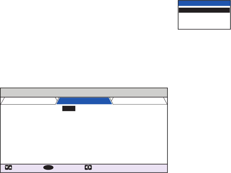
2. INLAND AIS OPERATION
2-5
is not changed from the default (+00:00) setting, the ETA indication appears as
"ETA [LT]".
Note 2: Where a GPS is not connected, or the signal is lost/interrupted, the ETA
indication appears as ETA [UTC]. Further, the settings pop up window displays
"NOTE: INPUT THE UTC" at the bottom of the pop up window.
5. Set the ETA date and time, referring to the figure on the previous page, then press
the ENT/ACK key.
6. Confirm that the AIS mode selected is correct for this voyage. If a mode change
is necessary, change the mode (See section 2.2), then repeat this procedure after
the system restarts. If no change is required, go to step 6.
7. Select [DYNAMIC INFO RATE], then press the ENT/ACK key. The settings pop
up window shown below appears.
If the report rate from a base station is used, this setting is
ignored. For that reason, this setting is not always the same
as the actual report rate.
8. Select the appropriate interval to send dynamic informa-
tion, then press the ENT/ACK key.
Note 1: This setting is fixed to [AUTO] when [AIS MODE] is set to [SOLAS].
Note 2: The new setting take effect after approximately 8 minutes. In the mean-
time, the [AUTO] setting is used, regardless of the on-screen indication.
9. Press to display the [SHIP’S INFO] tab.
10. [ERI CODE] is selected. Press the ENT/ACK key to edit the ERI code type for this
voyage.
For [SOLAS] mode, the [ERI CODE] item is replaced with [CARGO TYPE].
11. Input the ERI code, referring to "ERI Codes" on page AP-12, then press the ENT/
ACK key.
Note: When [Tanker] is selected and the Nav status is [Moored], output power is
automatically switched to 1 W when SOG is less than 3 knots. Further, in the
above condition, when SOG becomes higher than 3 knots, a beep sounds. (The
pop-up message "TX POWER CHANGED" also appears to notify you that the Tx
power has changed). To erase the pop-up message, press the ENT/ACK key or
reduce SOG to below 3 knots.
For SOLAS mode, input the cargo type, referring to step 7 of section 1.6.
DYNAMIC INFO RATE
AUTO
10 sec
5 sec
2 sec
NAV STATUS
: TAB
: SELECT:
CURSOR
ENT
VOYAGE
SHIP’S INFO SCALE
ERI CODE
BLUE CONES
UN/LOADED
PASSENGER
CREW
TANKBARGE
UNKNOWN
- - - - - - - -
254
8190
8160
:
:
:
:
:
PERSONNEL
254
:
NO. OF PERSONS
:
8191