Furuno USA 9ZWFA170 Automatic Identification Systems User Manual OME 44900 A
Furuno USA Inc Automatic Identification Systems OME 44900 A
Contents
- 1. Installation Manual
- 2. Installation Manual II
- 3. User Manual
- 4. User Manual II
User Manual II

2. INLAND AIS OPERATION
2-6
12. Select [BLUE CONES], then press the ENT/ACK key. The pop up window shown
below appears.
Depending on the cargo, up to four “cones” have to be shown on the mast, in day-
light with cones and nighttime with blue lights. The greater the number of the
cones the more hazardous the cargo.
• Select [NO. OF CONES 0] if your ship is not carrying hazardous cargo.
• Select [B-FLAG] if your ship carries explosives or hazardous cargo that ex-
ceeds the hazard level expressed with cones.
• Select [UNKNOWN] if you are unsure of cargo type.
13. Set [BLUE CONES] as necessary, then press the ENT/ACK key.
14. Select [UN/LOADED], then press the ENT/ACK key. The
pop up window shown to the right appears.
15. Select [LOADED] for vessel loaded with cargo, [UNLOAD-
ED] for vessel with no cargo, or [- - -] if you are unsure of the
loading status.
16. Select [CREW] is now selected, then press the ENT/ACK key.
17. Enter number of crew (0-254) then press the ENT/ACK key.
18. Select [PASSENGER], then press the ENT/ACK key.
19. Enter number of passengers (0-8190) then press the ENT/ACK key.
20. Select [PERSONNEL], then press the ENT/ACK key.
21. Enter number of shipboard personnel (persons other than passengers and crew,
0-254) then press the ENT/ACK key.
Note: Crew, passenger and shipboard personnel are sent in RFM55 messages.
22. [NO. OF PERSONS] is selected; press the ENT/ACK key.
23. Enter the total number of persons (sum of crew, passengers and shipboard per-
sonnel) on-board then press the ENT/ACK key.
Note: If the value entered for [CREW], [PASSENGER], [PERSONNEL] or [NO.
OF PERSONS] exceeds the maximum setting listed in the steps above, the value
appears as maximum for that item.
BLUE CONES
UNKNOWN
NO . OF CONES 1
NO . OF CONES 2
NO . OF CONES 3
B-FLAG
NO . OF CONES 0
UN/LOADED
LOADED
UNLOADED
2. INLAND AIS OPERATION
2-7
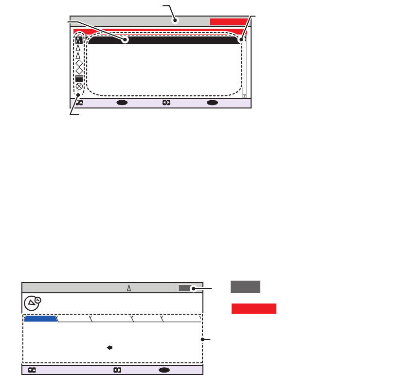
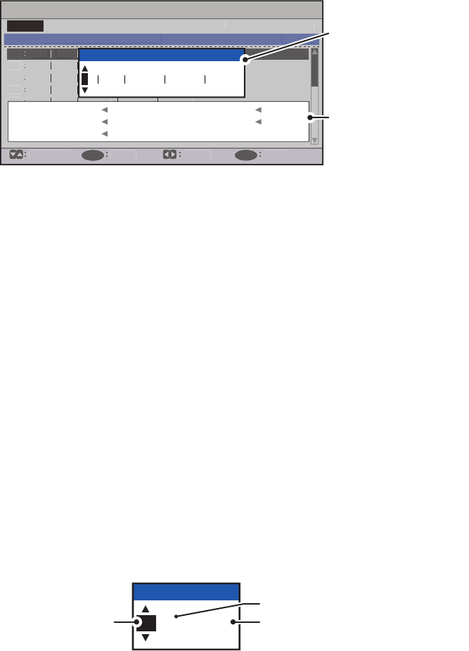
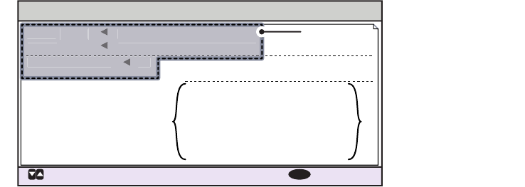
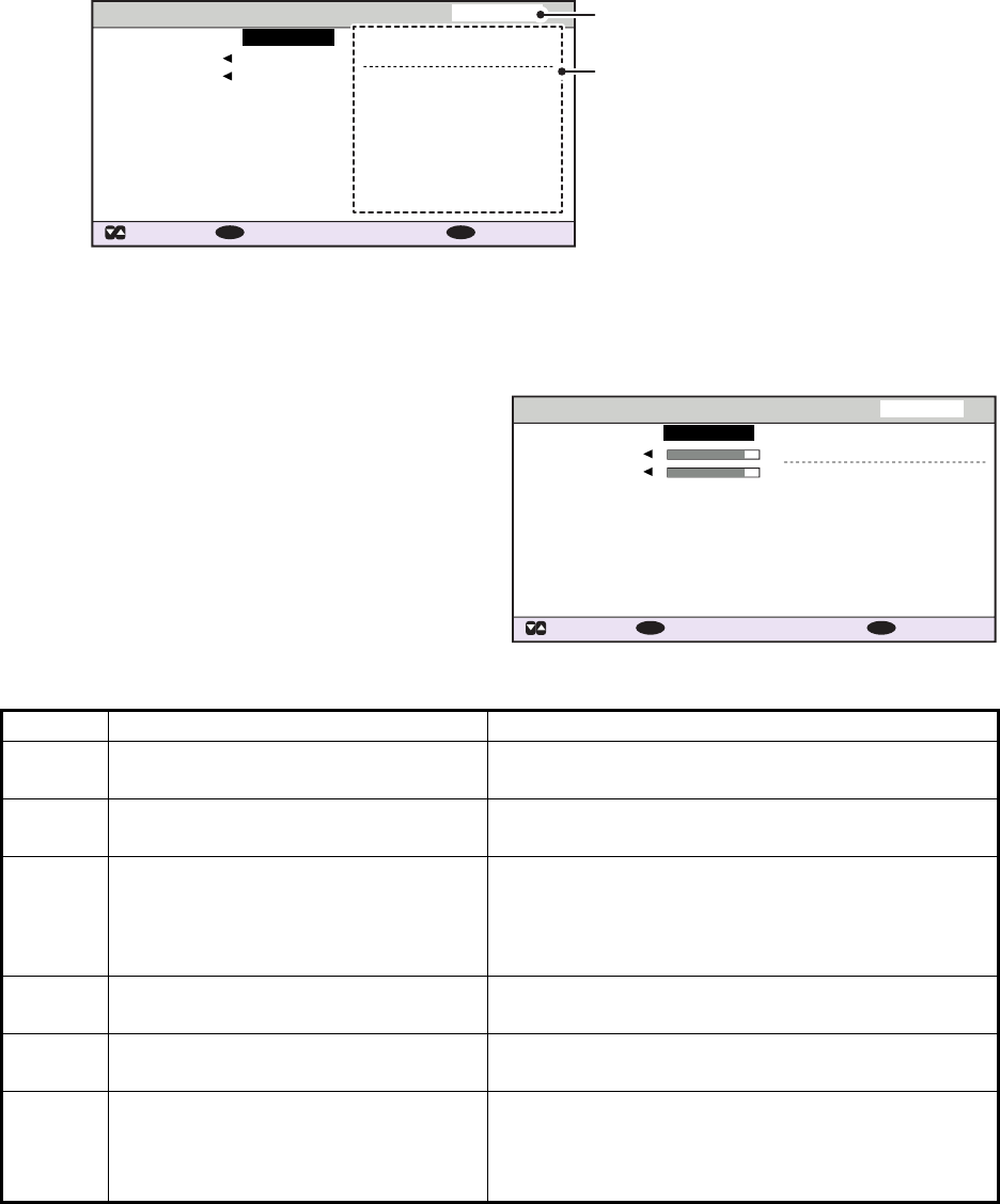
24. Press to display the [SCALE] tab.
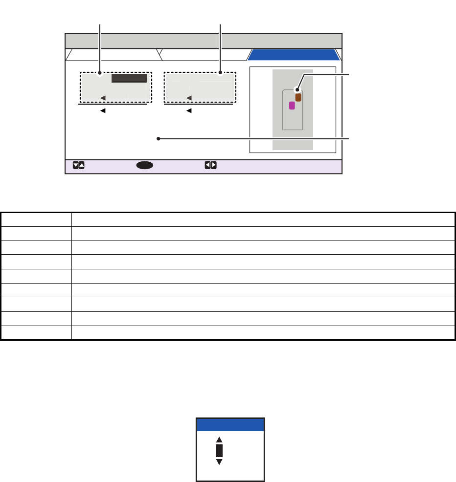
25. Referring to the table below, input the length and beam of your vessel and the con-
voy vessel.
Press the arrow keys to move the selection cursor and highlight the item you wish
to edit, then press the ENT/ACK key. A numerical input pop up window appears
for the selected item.
26. Select [DRAUGHT], then press the ENT/ACK key to display the [DRAUGHT] set-
ting pop up window. The setting range is [0] cm to [2000] cm.
27. Input the draught, then press the ENT/ACK key.
28. Press the DISP key to close the menu.
Menu item Description
[EA] Length of convoy vessel A. Setting range [0] to [6800] dm.
[EB] Length of convoy vessel B. Setting range [0] to [6800] dm.
[EC] Beam of convoy vessel A. Setting range [0] to [400] dm.
[ED] Beam of convoy vessel B. Setting range [0] to [400] dm.
[LS] Own ship length. (Display only, not available for input.)
[BS] Own ship beam. (Display only, not available for input.)
[LC] Shows the total length of the convoy. (Display only, not available for input.)
[BC] Shows the total beam of the convoy. (Display only, not available for input.)
NAV STATUS
: TAB
: SELECT:
CURSOR
ENT
VOYAGE
DRAUGHT
SHIP’S INFO SCALE
EA
:
[CONVOY EXTENSION]
0000dm
EB
LS
LC
:
0000dm
:
0000cm
0dm
0dm
0dm
0dm
ED
BS
BC
:
0000dm
EC
:
0000dm
1
2
0dm
ED
BS
:
0000dm
EC
:
0000dm
EA
:
0000dm
EB
L
S
:
0000dm
0dm
Convoy
layout
Own vessel and convoy
vessel lengths
Own vessel and convoy
vessel beams
Own ship
draught
0000
[0 , 2000 ]
DRAUGHT
2. INLAND AIS OPERATION
2-8
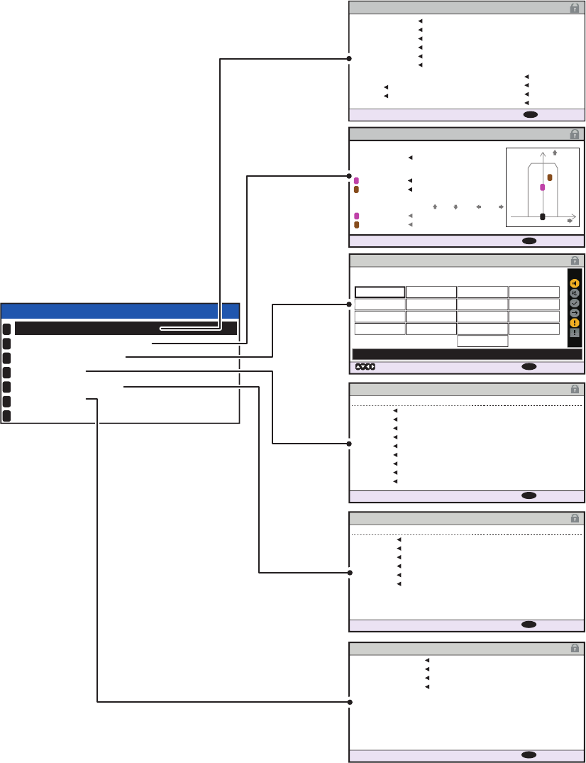
2.4 Static Data
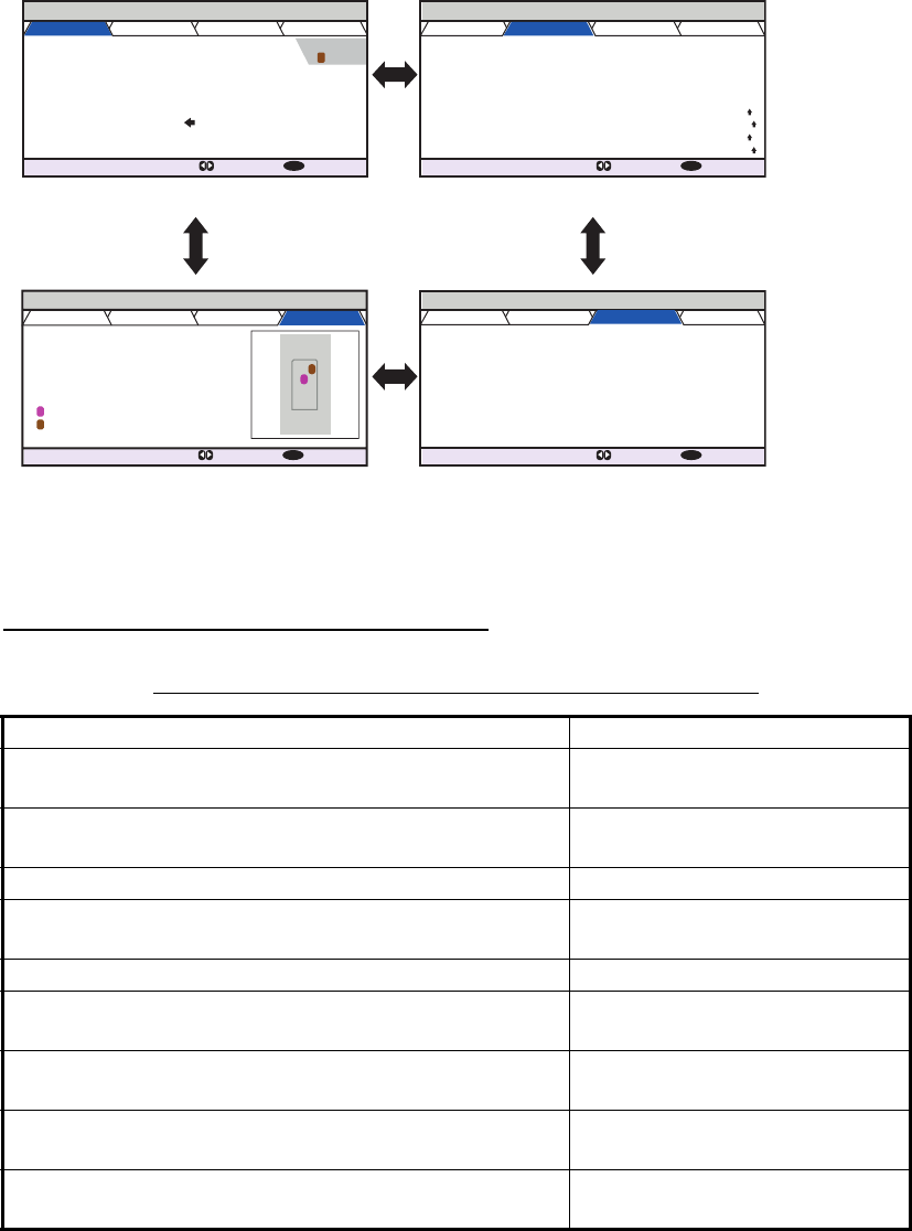
The [OWN INFORMATION] display shows your ship’s data across four tabs. The in-
formation displayed is shown in the figure below. This data should be checked once
per voyage or once per month whichever is shorter. Data may be changed only on the
authority of the master.
The Officer of the Watch should periodically check position, SOG and sensor informa-
tion for quality.
Note: The [TYPE OF SHIP] indication on the [IDENTITY] tab changes to display the
ERI code when INLAND mode is active.
Update rate of dynamic ship information
Ship’s dynamic conditions and nominal reporting interval
Ship’s dynamic conditions Nominal reporting interval
Ship at anchor or moored or aground or not under
command and not moving faster than 3 kn
3 minutes
Ship at anchor or moored or aground or not under
command and moving faster than 3 kn
10 seconds
Ship operating in SOLAS mode, moving 0-14 kn 10 seconds
Ship operating in SOLAS mode, moving 0-14 kn
speed and changing course
3 1/3 seconds
Ship operating in SOLAS mode, moving 14-23 kn 6 seconds
Ship operating in SOLAS mode, moving 14-23 kn and
changing course
2 seconds
Ship operating in SOLAS mode, moving faster than 23
kn
2 seconds
Ship operating in SOLAS mode, moving faster than 23
kn and changing course
2 seconds
Ship operating in inland waterway mode Assigned between 2 seconds
and 10 minutes
OWN INFORMATION
: TAB : NEXT
DISP
SENSOR VOYAGE IDENTITY SCALE
UTC
12/NOV/2014 17 :20 :00
34 º 44 .5000 ´N
130 .0º
135 .0º
135 º 21.3000 ´E
708 . 7 º/min ( )
10 .0 kn
HIGH
UNUSED
POSN PA
RAIM
HDG
COG
ROT
SOG
OWN INFORMATION
: TAB : NEXT
DISP
SENSOR VOYAGE IDENTITY SCALE
NAV STATUS
DESTINATION
ETA(UTC)
NO. OF PERSONS
PERSONNEL
PASSENGER
BLUE SIGN YES
NO. OF CONES 1
UNLOADED
BLUE
CONES
UN/LOADED
CREW
PWR-DRIVEN VESSEL PUSHING
AHEAD OR TOWING ALONGSIDE
KOBE
10 /
MAY
10:51
12
OWN INFORMATION
: TAB : NEXT
DISP
SENSOR VOYAGE IDENTITY SCALE
MMSI
NAME
IMO NO.
CALL SIGN
TYPE OF SHIP
WIG
ARRYING DG, HS, OR, MP(OS)
24
@SEVEN@
ENI
@EIGHT@
FURUNOMARU
2974091719
0123456789
SENSOR tab VOYAGE tab
IDENTITY tabSCALE tab
Press ► or ◄ to cycle
through the tabs.
255
8191
255
8191
OWN INFORMATION
: TAB : NEXT
DISP
SENSOR VOYAGE IDENTITY SCALE
[CONVOY EXTENSION]
[ANT POSN]
EA
500dm
500dm
1000dm
400dm,600dm,250dm,250dm
200dm,800dm,400dm,100dm
0cm
2000dm
500dm
250dm
250dm
1000dm
EB
LS
INT
EXT
DRAUGHT
LC
EC
EC
BS
BC
A, B, C, D
2
1
1
2
EXTERNAL
DGPS
2
2. INLAND AIS OPERATION
2-9
2.5 Target List and Dangerous Target List
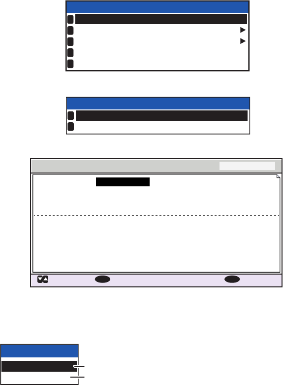
2.5.1 Target list
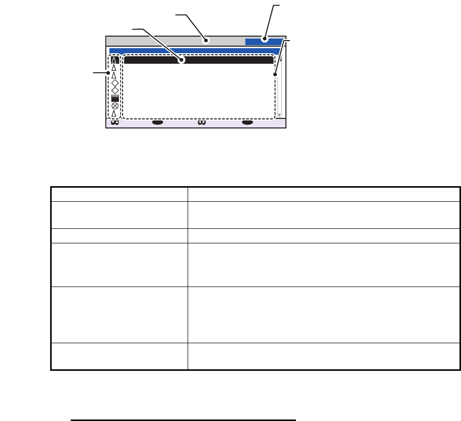
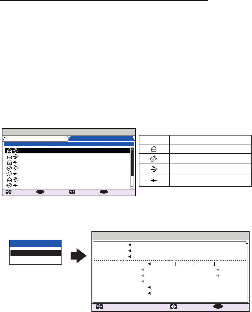
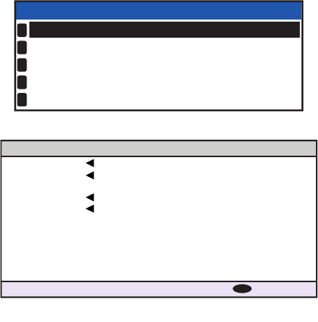
The [TARGET LIST] can store up to 2048 AIS targets and AIS-SARTs being detected
by the FA-170, in the order which they are detected. The list can be sorted in range
order, from closest to farthest.
1. Press the DISP key until the [TARGET LIST] or [DANGEROUS LIST] appears.
Note: The last views list ([DANGEROUS LIST] or [TARGET LIST]) is displayed.
Targets are displayed in groups of 100, however only eight targets are displayed
on the screen at any time. The following operations are used in the TARGET LIST.
The [NAME/MMSI/TYPE] column of the [TARGET LIST] displays the target ves-
sel’s type in the following formats:
For CLASS A/CLASS B/AtoN type targets
Where the vessel name is available, the name is displayed. Where no name data
is available, the MMSI is displayed.
Operation Description
Press or . Scroll up or down the list of targets. The selected target
is highlighted.
Press or . Move to the next group of targets (next 8 targets).
Select [NEXT 100 TAR-
GETS], then press the
ENT/ACK key.
Move to the next page of the target list (next 100 targets).
Note: Displayed only if more than 100 targets are detect-
ed.
Select [PREVIOUS 100
TARGETS], then press the
ENT/ACK key.
Move to the previous page of the target list (last 100 tar-
gets).
Note: Displayed only if more than 100 targets are detect-
ed.
Select a target, then press
the ENT/ACK key.
Display the selected target’s details. See section 2.5.3
for details.
TARGET LIST 12:32:01
81-88(334)
: CURSOR
: FUNC
ENT
: PAGE : NEXT
DISP
NAME/MMSI/TYPE
RNG[km] BRG[ º ] AGE[ ‘
]
B
A
A
SAR
B
SAMPLE SHIP 003 3 .5 100.0 0
SAMPLE SHIP 004 3 .6 110.0
SAMPLE SHIP 005 3 .7 120.0 0
SAMPLE SHIP 006 3 .8 130.0 0
SAMPLE SHIP 007 3 .9 140.0 0
SAMPLE SHIP 008 3 .1 150.0 0
SAMPLE SHIP 002 3 .4 090.0 0
SAMPLE SHIP 002 3 .3 080.0 0
NAME/MMSI/TYPE: Target’s MMSI,
name or type is displayed. Where
name data is available, the vessel
name is displayed.
RNG[km]: Range from OS to target.
BRG[ º ]: Bearing to target.
AGE[ ‘ ]: Time (in minutes) since the
target data was last updated.
Target type symbols.
See Appendix 5 of the
operator’s manual for a
full list of AIS symbols
and their meanings.
Selected target is highlighted.
Time at which the list was last sorted.
Currently displayed target group.
Total detected targets is displayed in
brackets.
2. INLAND AIS OPERATION
2-10
For SAR(VESSEL/AIRCRAFT)/SART/MOB/EPIRB type targets
Note 1: If there is no data for the target selected, the fields are displayed as "=NO
TARGET=".
Note 2: Targets are automatically sorted in range order (closest to furthest) when
no key is operated for 30 seconds. Target order is then updated every five sec-
onds.
Active AIS-SARTs take priority and are displayed at the top of the list.
Note 3: When [AUTO SORT] on the [USER SET] menu is [OFF], the range and
bearing to a target are updated. However, target order is not updated. To manu-
ally sort targets, see step 2.
Note 4: To select a target on the plotter display, press or to select the target
then press the ENT/ACK key. Press to cycle through targets from nearest to
furthest; to cycle through targets from furthest to nearest.
2. To view target data, or to sort the target list, select the desired target, then press
the ENT/ACK key. The target list options pop up window appears.
• [SORT (NORMAL)]: Press to display and sort the [TARGET LIST] into range
order. The closest target is displayed at the top of the list.
• [SORT (DANGER)]: Press to display and sort the [DANGEROUS TARGET
LIST] in range order. The closest target is displayed at the top of the list.
• [VIEW DETAIL]: Press the ENT/ACK key to open the [TARGET DETAIL]
screen.
• [NEW MSG]: Press to open the text input window to create an AIS message
to the selected target.
• [NAME REQUEST]: Press to send a name request to the target vessel’s AIS.
Note: Name requests cannot be sent to the same target within a short period,
regardless of target. If you have requested the name of a target too soon after
the last request, or the target is out of range, or the target has set their AIS to
RX only mode, the pop up message "CANNOT REQUEST NAME" is displayed.
Wait a short while before requesting the name again.
3. Press the DISP key to close the menu.
TYPE Display format
SAR vessel "SAR/VESSEL"
SAR aircraft "SAR/AIRCRAFT"
SART Active "SART ACTIVE"
SART Test "SART TEST"
MOB Active "MOB ACTIVE"
MOB Test "MOB TEST"
EPIRB Active "EPIRB ACTIVE"
EPIRB Test "EPIRB TEST"
AIS Base station "BS: (station’s MMSI/name)"
FUNCTION
NEW MSG
VIEW DETAIL SORT
(DANGER)
SORT
(NORMAL)NAME REQUEST
ENT
2. INLAND AIS OPERATION
2-11
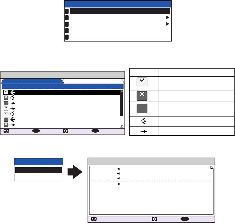
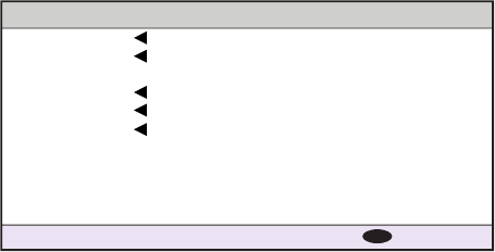
2.5.2 Dangerous (target) list
Dangerous targets are targets which are calculated to be on a collision course with
your vessel. When a dangerous target is detected, the target and its available details
can be viewed in the [DANGEROUS TARGET LIST].
The operations available from the [DANGEOUS TARGET LIST] are the same as the
[TARGET LIST] operations. See section 2.5.1 and section 2.5.3 for details.
Note: When no dangerous targets are detected, the list shows the message "= NO
TARGET =".
2.5.3 How to interpret the [TARGET DETAIL] screen
The [TARGET DETAIL] screen shows available detailed information about the select-
ed target.
Lost and dangerous targets have the appropriate icon displayed at the top right, as
indicated in the lost target example below.
There are five tabs available for viewing; [SENSOR], [VOYAGE], [IDENTITY],
[SCALE] and [QUALITY]. Press or to change the tab currently displayed.
The selected target’s bearing ([BRG]), range ([RNG]), [MMSI] and [NAME] are dis-
played at the top of the screen regardless of the selected tab. For lost or dangerous
targets, the appropriate icon is displayed at the top right of the screen.
The information displayed on each tab varies, depending on the type of target select-
ed.
The tables on the following pages list each tab’s contents, along with a brief descrip-
tion.
DANGEROUS LIST
12:32:01
9-16 (108)
: CURSOR
: FUNC
ENT
: PAGE : NEXT
DISP
SAMPLE SHIP 003 3 .5 100.0 0
SAMPLE SHIP 004 3 .6 110.0
SAMPLE SHIP 005 3 .7 120.0 0
SAMPLE SHIP 006 3 .8 130.0 0
SAMPLE SHIP 007 3 .9 140.0 0
SAMPLE SHIP 008 3 .1 150.0 0
SAMPLE SHIP 002 3 .4 090.0 0
SAMPLE SHIP 002 3 .3 080.0 0
NAME/MMSI/TYPE
RNG[km] BRG[ ° ] AGE[ ‘
]
B
A
A
SAR
B
Target type symbols. See Appendix 5 for a
full list of AIS symbols and their meanings.
NAME/MMSI/TYPE: Target’s MMSI,
name or type is displayed. Where
name data is available, the vessel
name is displayed.
RNG[km]: Range from OS to target.
BRG[ º ]: Bearing to target.
AGE[ ‘ ]: Time (in minutes) since the
target data was last updated.
Selected target
is highlighted.
Time at which the list was last sorted.
TARGET DETAIL
: TAB: TARGET : BACK
MENU
SENSOR VOYAGE IDENTITY SCALE QUALITY
CLASS A
FURUNOMARU
TYPE
34 º 44 .5000 ´N
130 .0º
135 .0º
135 º 21.3000 ´E
108 . 7 º/min ( )
10 .0 km/h
POSN
HDG
COG
ROT
SOG
225.4º
3.02NM
BRG
RNG 201503030
NAME
MMSI
LOST
AThe LOST icon is displayed for
lost targets.
The DANGER icon is displayed
for dangerous targets.
When data input to the FA-170 is
interrupted or stopped, indications
for all tabs appear as “----”.

2. INLAND AIS OPERATION
2-12
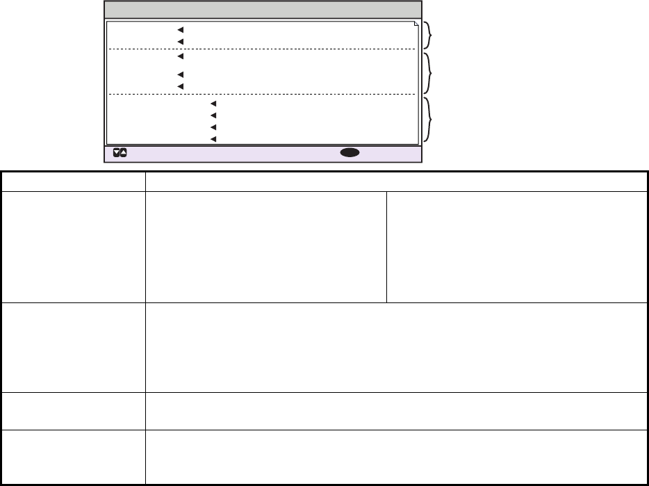
SENSOR tab
VOYAGE tab
The VOYAGE tab is only displayed for CLASS A target types and has two pages.
IDENTITY tab
The IDENTITY tab is only displayed for CLASS A, CLASS B, SAR VESSEL, SAR AIR-
CAFT and AtoN target types.
Contents Description
POSN Target’s last known position. Displayed for all target types.
ROT Target’s Rate Of Turn. Displayed only for CLASS A, SART, MOB and EPIRB target
types.
ALT Altitude. Displayed only for SAR VESSEL and SAR AIRCRAFT target types.
SOG Target’s Speed Over Ground. Displayed only for CLASS A, CLASS B, SAR VESSEL,
SAR AIRCRAFT, SART, MOB and EPIB target types.
COG Target’s Course Over Ground. Displayed only for CLASS A, CLASS B, SAR VESSEL,
SAR AIRCRAFT, SART, MOB and EPIB target types.
HDG Target’s last known heading. Displayed only for CLASS A, CLASS B, SART, MOB and
EPIRB target types.
Contents Description
NAV STATUS Target’s navigational status (see section 1.6 for details).
DESTINATION Target’s destination.
ETA Target’s Estimated Time of Arrival at the above destination.
BLUE SIGN Indicates if the target is carrying hazardous cargo.
BLUE CONES Indicates the number of blue cones (type of hazardous cargo) carried by the
target.
UN/LOADED Indicates if the target is loaded or unloaded.
CREW Indicates the number of crew aboard the target.
PASSENGERS Indicates the number of passengers aboard the target.
PERSONNEL Indicates the number of personnel aboard the target.
NO. OF PERSONS Indicates the total number of people aboard the target.
Contents Description
CALL SIGN Target’s call sign. Not displayed for AtoN target types.
IMO NO. Target’s International Maritime Organization registration number.
TYPE OF SHIP Target’s ship type. Displayed only for CLASS A and CLASS B target types.
REAL AtoN Displayed as "YES" for physical aids to navigation, "NO" for virtual aids to nav-
igation. Displayed only for AtoN target types.
TYPE OF AtoN The type of aid to navigation. Displayed only for AtoN target types.
VENDER ID Target’s AIS maker's ID. Displayed only for CLASS B target types.
ENI Target’s ENI (Unique European Vessel Identification Number).
ERI CODE Target’s ERI (Electronic Reporting International ship type) code.

2. INLAND AIS OPERATION
2-13
SCALE tab
The SCALE tab is only displayed for SAR VESSEL, SAR AIRCRAFT and AtoN target
types.
QUALITY tab
The QUALITY tab is displayed for all target types.
Contents Description
SHIP SIZE(LENGTH, BEAM) Target’s ship size (length, beam). Displayed for all above target
types.
ANT POSN(X,Y) Position of target’s antenna. Displayed for all above target types.
DRAUGHT Target ship’s draught. Displayed only for CLASS A target types.
PI Target’s position. Displayed only for AtoN target types.
CONVOY Target’s convoy length and beam.
Contents Description
PA Position Accuracy for target ship. (H: High accuracy, L: Low accuracy.)
RAIM Target’s RAIM status. (USED: Using RAIM, UNUSED: Not using RAIM.).
TIME STAMP Time at which the target was last detected. Not displayed for AIS base stations.
POSN
QUALITY
Target’s position quality. Possible position qualities are shown in the list below:
Quality indication Meaning
No position Position data not available.
Manual position Position data is input manually.
Dead reckoning position Position calculated by dead
reckoning.
Outdated position > 200 m More than 200 m from last
estimated position.
Position > 10 m Difference of more than 10 m from last es-
timated position.
Position with RAIM > 10 m Difference of more than 10 m from last es-
timated position.
Position < 10 m Difference of less than 10 m from last esti-
mated position.
Position with RAIM < 10 m Difference of less than 10 m from last esti-
mated position.
Valid position with no time stamp No time stamp available.
HDG/SOG/
COG QUALI-
TY
Target’s sensor quality. Possible sensor qualities are shown in the list below:
Quality indication Meaning
HIGH Target is equipped with sensors which
meet the requirements of the VTT Standard
for Inland Navigation.
LOW Target is not equipped with sensors which
meet the requirements of the VTT Standard
for Inland Navigation.
2. INLAND AIS OPERATION
2-14
2.6 Inland AIS Specific Messaging
All sent and received messages are stored in their respective message box. Refer to
the appropriate section below for how to view messages once they are sent or re-
ceived.
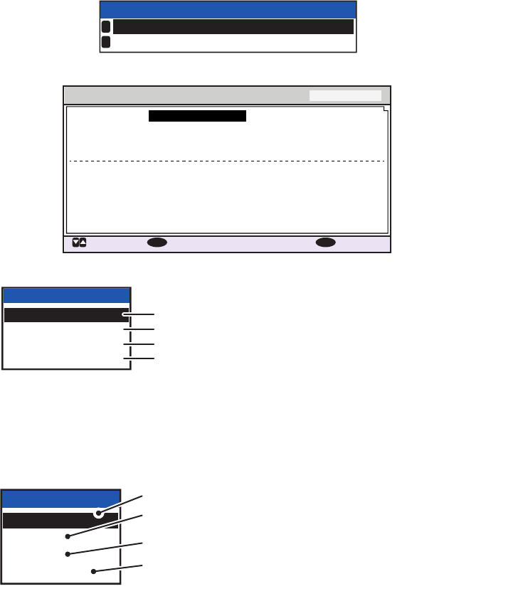
2.6.1 How to send a text message
1. Press the MENU/ESC key to open the menu.
2. Select [MSG], then press the ENT/ACK key.
3. [TEXT] is selected, press the ENT/ACK key.
4. Select [NEW MSG], then press the ENT/ACK key.
5. [MSG TYPE]is selected, press the ENT/ACK key to change the type of message
you wish to send. The options pop up shown below appears.
6. Select the appropriate message type, then press the ENT/ACK key.
For broadcast messages, skip to step 9.
7. Select [TO], then press the ENT/ACK key. A numerical settings pop up appears.
8. Input the MMSI of the ship you wish to send this message to, then press the ENT/
ACK key to close the pop up. See section 1.5 for how to input data.
MSG
TEXT
ETA/RTA
NO. OF PERSONS
WATER LEVEL BOX
EMMA WARNING BOX
1
2
3
4
5
TEXT
NEW MSG
MSG BOX
1
2
NEW MSG TEXT
( )
MSG TYPE
<SEND MSG>
: CURSOR
: SELECT
ADDRESSED
: BACK
ENT
MENU
:
TO 000000000
:
CH ALTERNATE
:
RETRY 3
:
TEXT
( 0 / 85 )
Use the software keyboard
to enter the message here.
:
MSG TYPE
BROADCAST
ADDRESSED
Message to all vessels.
Message to specified vessel only.

2. INLAND AIS OPERATION
2-15
9. Select [CH] (Channel), then press the ENT/ACK key. The channel select options
pop up appears.
10. Select the appropriate option, then press the ENT/ACK key.
For broadcast messages, skip to step 13.
11. Select [RETRY], then press the ENT/ACK key. The retry attempts setting pop up
appears.
12. Press to increase the retry attempts, to decrease the retry attempts. The
maximum setting for retries is 3. Press the ENT/ACK key to apply the setting and
close the pop up.
13. Press to highlight the message text, then press the ENT/ACK to display the
software keyboard.
14. Input the new message text, referring to section 1.5.4. The maximum number of
characters allowed is as follows:
• BROADCAST: 90 characters.
• ADDRESSED: 85 characters.
15. Press or to highlight [<SEND MSG>] at the top right of the screen, then press
the ENT/ACK key. A confirmation pop up appears.
16. Select [YES] to send the message or [NO] to cancel the message, then press the
ENT/ACK key.
CH
BOTH A & B
ONLY A
ONLY B
ALTERNATE
Sends the same message to both channel A and channel B.
Sends the message to channel A only.
Sends the message to channel B only.
Sends messages on alternating channels. In other words, if
the last message sent on channel A, the next message is
sent on channel B.
2. INLAND AIS OPERATION
2-16
2.6.2 How to view a sent text message
1. Press the MENU/ESC key to open the menu.
2. Select [MSG], then press the ENT/ACK key.
3. Select [TEXT], then press the ENT/ACK key.
4. Select [MSG BOX], then press the ENT/ACK key. The message box appears.
5. Select the message you wish to view, then press the ENT/ACK key. The message
options pop up window shown below appears.
Select [VIEW DETAIL], then press the ENT/ACK key to display the received mes-
sage’s contents. The figure above shows an example of a received message.
Select [NEW MSG], then press the ENT/ACK key to send a message back to this
message’s sender.
6. Press or to view other messages, press or to switch between viewing
an [INBOX] message and an [OUTBOX] message.
7. Press the DISP key to close the menu.
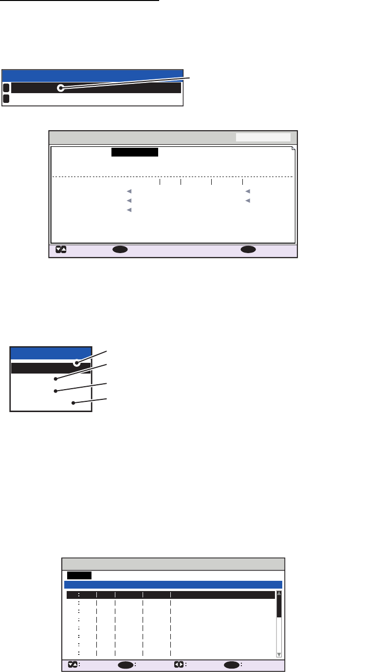
2.6.3 ETA and RTA messages
The purpose of an ETA message is to apply for a time slot at a lock, bridge or terminal.
(Hereafter “lock” refers to lock, bridge or terminal.) The message contains your ship's
ETA at the lock, air draught, the number of assisting tugboats required and the partic-
ulars of the lock (country code, location code, etc.).
Upon receipt of your ETA message, the lock authority responds with an RTA (Re-
quested Time of Arrival) message, usually within 15 minutes of receipt of the ETA
message. The RTA message contains lock operational status, requested time of ar-
rival and the particulars of the lock (country code, location code, etc.).
MSG
TEXT
ETA/RTA
NO. OF PERSONS
WATER LEVEL BOX
EMMA WARNING BOX
1
2
3
4
5
MSG BOX ( TEXT )
INBOX: 12
OUTBOX: 10
TIME [UTC]
30 /MAY 18 : 25
BROADCAST
BROADCAST
TITANIC
NAUTILUS
BROADCAST
BROADCAST
MUSASHIMARU
29 /MAY 16 :05
28 /MAY 16 :15
27 /MAY 17 :20
26 /MAY 17 :20
25 /MAY 17 :20
24 /MAY 17 :20
TO 01 / 10
: CURSOR
: FUNC
ENT
: TAB
: BACK
MENU
Indication Meaning
This message was sent
successfully.
This message was not sent.
Waiting for recipient to
acknowledged this message.
Broadcast message
Addressed message
NO
ACK
NO
ACK
OK
OK
OK
OK
NG
NG
NO
ACK
NG
FUNCTION
VIEW DETAIL
NEW MSG
MENU
INBOX MSG DETAIL ( TEXT )
MSG TYPE ADDRESSED
28 / MAY 16 : 15
987654321 / ENTERPRISE
KLINGONS ON STBD BOW.
TIME [UTC]
TO
TEXT
( 21)
: BACK: BOX: MESSAGE
2. INLAND AIS OPERATION
2-17
How to send an ETA message
1. Press the MENU/ESC key to open the menu.
2. Select [MSG], then press the ENT/ACK key.
3. Select [ETA/RTA], then press the ENT/ACK key.
4. Select [NEW MSG], then press the ENT/ACK key.
5. [TO] is selected. Press the ENT/ACK key. to display the MMSI settings pop up
window.
6. Enter the MMSI of the lock/bridge/terminal you want to pass through then press
the ENT/ACK key.
7. Select [CH], then press the ENT/ACK key.
8. Select the channel over which to send the message then press the ENT/ACK key.
9. Select [RETRY], then press the ENT/ACK key. The retry attempts setting pop up
appears.
10. Press to increase the retry attempts, to decrease the retry attempts. The
maximum setting for retries is 3. Press the ENT/ACK key to apply the setting and
close the pop up.
11. Select [DESTINATION] then press the ENT/ACK key. The [INLAND DESTINA-
TION LIST] appears.
ETA/RTA
NEW MSG
MSG BOX
1
2
The [NEW MSG] option in the [ETA/RTA]
pop up window is not available for selection
in [SOLAS] mode.
NEW MSG (ETA)<SEND MSG>
: CURSOR
: SELECT
000000000
: BACK
ENT
MENU
:
TO
CH
RETRY
DESTINATION
COUNTRY CODE
FAIRWAY NO.
FAIRWAY HECT
ETA[UTC]
AIR DRAUGHT
NO. OF TUGBOATS
:
ALTERNATE
:
:
:
:
:
3
DE
DE
LOCATION
CODE
TRI
11111
TERMINAL
CODE
01234
56789
12/
MA
Y
0 .0cm
0
12:32
TRI
01234
11111
56789
CH
BOTH A & B
ONLY A
ONLY B
ALTERNATE
Sends the same message to both channel A and channel B.
Sends the message to channel A only.
Sends the message to channel B only.
Sends messages on alternating channels. In other words, if
the last message sent on channel A, the next message is
sent on channel B.
INLAND DESTINATION LIST
<EDIT>
DE TRI 01234 11111 56789
00000 00000
00000 00000
00000 00000
00000 00000
00000 00000
00000 00000
00000 00000
07
06
05
04
03
02
01
08
INLAND DESTINATION
<COPY>
CURSOR
EXEC FUNC
BACK
<PASTE>
<CUT>
<SET>
01 / 20
ENT
MENU
2. INLAND AIS OPERATION
2-18
12. Referring to section 2.3, select or edit an existing destination or create a new des-
tination. The figure below shows an example destination and the edit pop up win-
dows.
When setting an destination for the [INLAND DESTINATION LIST] the following
details are required.
• Country code: The UN country code of your destination. (Referring to ISO
3166.)
• Three letter location code.
• Fairway number and hectometer.
• Terminal code.
Note: For location codes, fairway numbers (and hectometers) and terminal codes,
refer to the ERI (Electronic Reporting International) Guide Part IV Annex 2 for ex-
amples.
13. Input or edit the destination as appropriate, then press the ENT/ACK key.
Press to increase the value (or the next character, in alphabetical order), press
decrease the value (or the previous character, in alphabetical order). Press
to move the selection cursor to the right, to move the cursor to the left.
14. Select [<SET>], then press the ENT/ACK key.
15. Select [ETA (UTC)], then press the ENT/ACK key. The settings pop up window
shown below appears.
16. Select [AIR DRAUGHT], then press the ENT/ACK key.
17. Enter your ship's air draught then press the ENT/ACK key. (Air draught is the ver-
tical distance measured from the ship's waterline to the highest point on the ship.)
18. Select [NO. OF TUGBOATS], then press the ENT/ACK key.
19. Enter the no. of assisting tugboats (0-6) your ship requires then press the ENT/
ACK key. Enter [0] for none.
20. Press or to highlight [<SEND MSG>] at the top right of the screen, then press
the ENT/ACK key. The system will now attempt to send the message.
00000 00000
05
INLAND DESTINATION LIST
<EDIT>
DE TRI 01234 11111 56789
04
03
02
01
INLAND DESTINATION
<COPY>
CURSOR
EXEC FUNC
BACK
<PASTE>
<CUT>
<SET>
01 / 20
ENT
MENU
00000
00000
05
INLAND DESTINATION LIS
T
<
EDIT
>
D
E
TR
I
0123
4
11111
56
7
89
04
03
02
01
INLAND DE
S
TINATI
ON
<
COPY
>
C
UR
SO
R
EXE
C
F
UN
C
B
A
CK
<
PASTE>
<CUT
>
<
SET
>
01 / 2
0
ENT
MENU
TRI
01234
11111
56789
DE
COUNTRY CODE
FAIRWAY NO.
FAIRWAY HECT
LOCATION
CODE
TERMINAL CODE
TRI
01234
11111
56789
INLAND DESTINATION
DE
Editing pop up window.
Currently selected
destination’s details.
12 / 10 12:32
ETA (UTC)
ETA month
ETA day ETA time
in 24hr format
2. INLAND AIS OPERATION
2-19
How to view sent ETA messages and received RTA messages
A lock authority responds to an ETA message with an RTA message. An RTA mes-
sage contains the date and time the lock authority requests that your ship arrive to the
lock, lock status and the particulars of the lock (country code, location code, etc.)
When an RTA message is received, a pop up showing the message "RTA MESSAGE
RECEIVED." appears. The pop up also shows the sender’s MMSI ID, or the sender’s
name it if is included in the message.
To view past messages, do the following:
1. Press the MENU/ESC key to open the menu.
2. Select [MSG], then press the ENT/ACK key.
3. Select [ETA/RTA], then press the ENT/ACK key.
4. Select [MSG BOX], then press the ENT/ACK key. The message box appears.
Press or to switch between the [OUTBOX(ETA)] and [INBOX(RTA)] tabs.
5. Select the message you wish to view, then press the ENT/ACK key. The message
options pop up window shown below appears.
Select [VIEW DETAIL], then press the ENT/ACK key to display the received mes-
sage’s contents. The figure above shows an example of a received message.
Select [NEW MSG], then press the ENT/ACK key to send a message back to this
message’s sender.
6. Press or to view other messages, press or to switch between viewing
an [INBOX] message and an [OUTBOX] message.
7. Press the DISP key to close the menu.
MSG BOX (ETA/RTA)
INBOX(RTA): 12
OUTBOX(ETA): 10
TIME [UTC]
30 /MAY 17 : 20 BROADCAST
BROADCAST
ENTERPRISE
BROADCAST
NEPTUNE
BROADCAST
NAUTILUS
29 /MAY 16 :05
28 /MAY 16 :15
27 /MAY 17 :20
26 /MAY 17 :20
25 /MAY 17 :20
24 /MAY 17 :20
FROM 01 / 10
: CURSOR
: FUNC
ENT
: TAB
: BACK
MENU
Indication Meaning
This message has been viewed.
This message is unviewed.
Broadcast message
Addressed message
INBOX MSG DETAIL (RTA)
: MESSAGE : BOX
: BACK
MENU
MSG TYPE RTA
30 / AUG 18 : 30
FROM
TIME [UTC]
DESTINATION
COUNTRY CODE
FAIRWAY NO.
FAIRWAY HECT
ETA[UTC]
STATUS
MMSI / Sender’s name appears here
DE
DE
LOCATION
CODE
TRI
11111
TERMINAL
CODE
01234
56789
12/
MA
Y
LIMITED OPERATION
12:32
TRI
01234
11111
56789
FUNCTION
VIEW DETAIL
NEW MSG
2. INLAND AIS OPERATION
2-20
2.6.4 No. of persons message
A number of persons message informs authorities or ships how many persons (pas-
sengers, crew, shipboard personnel) you have on board your ship. Send this message
on request or in case of an event.
1. Press the MENU/ESC key to open the menu.
2. Select [MSG] then press the ENT/ACK key.
3. Select [NO. OF PERSONS] then press the ENT/ACK key.
4. Select [NEW MSG], then press the ENT/ACK key.
5. [MSG TYPE] is selected; press the ENT/ACK key.
6. Select the appropriate message type, then press the ENT/ACK key.
IFM messages require the total number of people on board.
RFM messages require a breakdown of the total people on board (No. of crew,
passengers and personnel).
7. Select [CH], then press the ENT/ACK key.
8. Select the channel to use to send the message then press the ENT/ACK key.
9. Select [RETRY], then press the ENT/ACK key. The retry attempts setting pop up
appears.
10. Press to increase the retry attempts, to decrease the retry attempts. The
maximum setting for retries is 3. Press the ENT/ACK key to apply the setting and
close the pop up.
11. Select and enter the total number for [NO. OF PERSONS] (IFM message) or
[CREW], [PASSENGER] and [PERSONNEL] (RFM message), then press the
ENT/ACK key.
12. Press or to highlight [<SEND MSG>] at the top right of the screen, then press
the ENT/ACK key. The system will now attempt to send the message.
NO. OF PERSONS
NEW MSG
MSG BOX
1
2
NEW MSG (PERSONS)
MSG TYPE
<SEND MSG>
: CURSOR
: SELECT
IFM / ADDRESSED
: BACK
ENT
MENU
:
TO 000000000
:
CH ALTERNATE
:
RETRY 3
:
NO. OF PERSONS : 0
MSG TYPE
IFM / BROADCAST
IFM / ADDRESSED
RFM / BROADCAST
RFM / ADDRESSED
IFM message to all vessels on the same channel.
IFM message to specified vessel only.
RFM message to all vessels on the same channel.
RFM message to specified vessel only.
CH
BOTH A & B
ONLY A
ONLY B
ALTERNATE
Sends the same message to both channel A and channel B.
Sends the message to channel A only.
Sends the message to channel B only.
Sends messages on alternating channels. In other words, if
the last message sent on channel A, the next message is
sent on channel B.
2. INLAND AIS OPERATION
2-21
2.6.5 EMMA warning message
EMMA (European Multiservice Meteorological Awareness) warnings are sent by base
stations to skippers to inform them of special meteorological situations. EMMA does
not provide continuous weather information, but only warnings of wind, rain, snow and
ice, thunderstorm, fog, extreme temperatures (low and high), flood, fire in the forest.
These messages are additional to the Notices to Skippers warnings.
When you receive an EMMA warning, the "EMMA WARNING RECEIVED" pop up
window appears and shows the MMSI or name of the sending agency. To see the con-
tents of the message, do the following:
1. Press the MENU/ESC key to open the menu.
2. Select [MSG] then press the ENT/ACK key.
3. Select [EMMA WARNING BOX] then press the ENT/ACK key.
4. Select a message then press the ENT/ACK key.
The EMMA warning message looks something like example below. To view the
other messages, press or .
5. Press the MENU/ESC key to close the message.
The information includes the following:
• Start time of validity
• End time of validity
• Fairway section start and end
co-ordinates
• Type of weather warning
• Minimum value
• Maximum value
• Classification of warning
• Wind direction
Item Description
TYPE [FIRE IN THE FORESTS], [FOG],
[FLOOD], [HIGH TEMPERATURE],
[LOW TEMPERATURE], [RAIN],
[SNOW AND ICE], [THUNDER-
STORM], [WIND]
Units of measurement are as follows:
• km/h (wind)
• °C (temperature)
• cm/h (snow)
• l/m2h (rain)
• m (visibility distance in fog)
MIN, MAX VALUE The minimum and maximum value of respective item over one hour. For ex-
ample, if the minimum and maximum values for snow and ice are 1 and 4 re-
spectively, this means that 1-4 cm of snow or ice has fallen in one hour.
The indication range is -254 to +254, or "- - - -" in case where a value is not
reported, for example, fire in the forests and flood.
CLASS Weather classification: [SLIGHT], [MEDIUM], [STRONG/HEAVY] or "- - - - -
- - -" (unknown)
WIND DIRECTION [NORTH], [NORTH EAST], [EAST], [SOUTH EAST], [SOUTH], [SOUTH
WEST], [WEST], [NORTH WEST] or "- - - -" (Where no wind data is avail-
able.)
EMMA WARNING MSG DETAIL
TIME [UTC]
30 /SEP 17: 20
26 /JAN 15: 00 ~ 26 / JAN 18 :00
34 º25 .0000 ‘N 34 º35 .0000 ‘N
134 º25 .0000 ‘E 134 º35 .0000 ‘E
123456789 / NAUTILUS
TERM
[UTC]
AREA
TYPE WIND
MEDIUM
NORTH EAST
36 ~ 50 [km/h]
CLASS
WIND
DIRECTION
VALUE (MIN~MAX)
FROM
: MESSAGE
: BACK
MENU
~
Time and date the
message was received.
Time frame (from date/time
to date/time) and area
(coordinates) of the warning.
Type of weather warning,
class of warning and other
details of the warning.
2. INLAND AIS OPERATION
2-22
2.6.6 Water level message
The water level message is sent by base stations to inform skippers about actual wa-
ter levels in their area. It is additional short-term information to the water levels distrib-
uted via Notices to Skippers. The message contains the country code (location),
gauge ID and water level.
When you receive a water level message, a pop up displays "WATER LEVEL MES-
SAGE RECEIVED.".
To see the contents of the message, do the following:
1. Press the MENU key to open the menu.
2. Select [MSG] then press the ENT/ACK key.
3. Select [WATER LEVEL BOX] then press the ENT/ACK key.
4. Select a message then press the ENT/ACK key.
5. Press the MENU/ESC key to close the message.
WATER LEVEL MSG DETAIL
4 . 24m
5 . 33m
1 . 23m
- 1 . 22m
TIME [UTC]
30 /SEP 17: 20
123456789 / NAUTILUS
FROM
COUNTRY CODE JP
GAUGE
ID
0007
0015
0255
2047
WATER LEVEL
: MESSAGE
: BACK
MENU
National unique gauge IDNational unique gauge IDNational unique gauge ID Positive or negative valuePositive or negative valuePositive or negative value
TIME
[
U
TC
]
30
/
S
EP 17: 2
0
12
3
4
56
7
89
/ NA
U
TIL
US
F
R
OM
COU
NTRY C
O
D
E
J
P
Time/date received, sender’s
details and country code.
Time/date received, sender’s
details and country code.
2. INLAND AIS OPERATION
2-23
2.7 Viewing Initial Settings
The [INITIAL SET] menu, which is locked with a password to prevent accidental
changes to the ship’s details, is where the installer enters ship’s MMSI, internal and
external antenna positions, ship type, I/O port settings and network settings. You can
view the settings on this menu as follows.
1. Press the MENU/ESC to open the menu.
2. Press the ENT/ACK key twice.
3. Select item to view then press the ENT/ACK key.
4. Press the DISP key to close the menu.
SHIP’S INFORMATION
MMSI 234567891
PERSEPHONE
987654321
00100000
@SEVEN@
NAME
IMO NO.
CALL SIGN
ENI
CH C 0075
CH D 0076
[LONG RANGE]
: BACK
MENU
24 (WIG)
TYPE OF SHIP
HIGHSPEED QUALITY
COURSE QUALITY
HEADING QUALITY
BLUE SIGN SW
HIGH
HIGH
USE
ANTENNA POSITION
: BACK
MENU
120dm 60dm
60dm
80dm
X
Y
2
1
0
[SHIP SIZE ] LENGTH BEAM
[ANT POSN] Y X
[ANT POSN]
A , B C , D
INTERNAL
EXTERNAL
INTERNAL
60 , 60
40 , 80
30 , 30
45 , 15
EXTERNAL
1
2
1
2
0dm
15dm
ALERT ENABLE
: BACK
: CURSOR
MENU
WARNING1
ENABLE
001 014
026
030
029
005
007
009
010
008
011
025
035
032
002
003
004
DISABLE
ENABLE
HI
LO
001 :
TX MALFUNCTION
DISABLE
WARNING2
: 8 : 0 : 0: 10
PORT
COM1
38400baud
38400baud
38400baud
38400baud
38400baud
38400baud
4800baud
4800baud
4800baud
COM2
COM3
COM4
COM5
COM6
SENSOR1
SENSOR2
SENSOR3 SENSOR
SENSOR
SENSOR
EXT
DISPLAY
EXT
DISPLAY
EXT
DISPLAY
EXT
DISPLAY
EXT
DISPLAY
LONG RANGE
MODE
SPEED
I / O PORT
: BACK
MENU
LOCK
SHIP’S INFORMATION
ANTENNA POSITION
ALERT ENABLE
I / O PORT
PORT PRIORITY
NETWORK
EDIT :
INITIAL SET
1
2
3
4
5
6
7
PRIORITY
LL /
SOG
/
COG
HDG
ROT
2nd
1st
3rd
4th
5th
6th
SENSOR1
SENSOR3 SENSOR3
SENSOR1 SENSOR1
SENSOR2 SENSOR2
SENSOR2
SENSOR3
COM4 COM6
COM4
COM5
COM6
COM4
COM5
COM5
COM6
PORT PRIORITY
: BACK
MENU
IP
ADDRESS
172 . 031 . 024 . 004
255 . 255 . 000 . 000
000 . 000 . 000 . 000
SUBNET MASK
GATEWAY
AI0001
SFI
NETWORK
: BACK
MENU
Note: The availability of some
functions depends on the
equipment specifications of your
vessel. Some items are not
displayed unless the vessel is
equipped accordingly.
Password access is required to
change these settings. Contact
your local dealer to change the
settings if required.
Displayed as “NETWORK (NAVNET)”
when the network type is set to [NAVNET].
2. INLAND AIS OPERATION
2-24
2.8 Setting for Time Difference
You can set the time differences from UTC (Coordinated Universal Time) to show the
local time.
1. Press the MENU/ESC key to open the menu.
2. Select [USER SET] then press the ENT/ACK key.
3. Select [TIME DIFF], then press the ENT/ACK key. The settings pop up window is
displayed.
4. Select the desired time difference then press the ENT/ACK key. You can change
the value with or , the digit with or The setting range is -14:00 to +14:00.
5. Press the DISP key to close the menu.
Note: When a UTC time offset is set, the time display indication for messages and
NAV STATUS screen is indicated as "LT" (Local Time). When there is no offset, the
time display indication for messages and the NAV STATUS screen is indicated as
"UTC" (Coordinated Universal Time).
USER SET
KEY BEEP
AUTO SORT
TIME DIFF
ON
HIDE
AUTO
+00 : 00
ON
SART TEST
LR RESPONSE
LR BROADCAST
NOTIFICATION SET
ACTIVATE
1
2
3
4
5
6
7
8
ON
+ 00:00
[ -14 : 00 , 14 : 00 ]
3-1
3. MAINTENANCE, TROUBLE-
SHOOTING
3.1 Maintenance
Regular maintenance is necessary to maintain performance. A monthly maintenance
program should be established and should at least include the items listed in the table
below.
Item Check point
Connectors Check that all connectors on the rear panel of the transponder unit
and monitor unit are firmly connected.
Cabling Check cabling for damage. Replace if damaged.
Ground terminal Check the ground terminal on the monitor unit and transponder unit
for rust. Clean if necessary.
Ground wire Check that the ground wire on the monitor unit and transponder unit
is firmly fastened.
Monitor unit,
Transponder
unit.
Dirt and dust should be removed from units with a soft, dry cloth. For
the LCD, wipe it carefully to prevent scratching, using tissue paper
and an LCD cleaner. To remove dirt or salt deposits, use an LCD
cleaner, wiping slowly with tissue paper so as to dissolve the dirt or
salt. Change paper frequently so the salt or dirt will not scratch the
LCD. Do not use solvents such as thinner, acetone or benzene for
cleaning any unit; they can remove paint and marks and deform the
equipment.
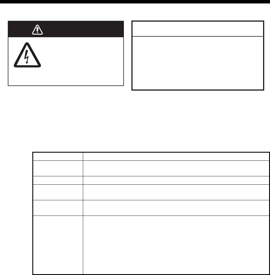
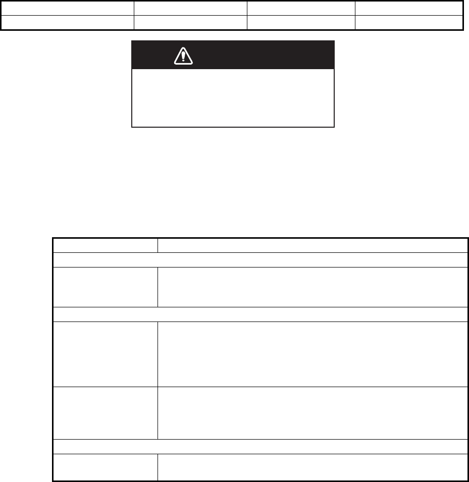
WARNINGWARNING
ELECTRICAL SHOCK HAZARD
Do not open the equipment.
Only qualified personnel
should work inside the
equipment.
NOTICE
Do not apply paint, anti-corrosive sealant
or contact spray to coating or plastic
parts of the equipment.
Those items contain organic solvents that
can damage coating and plastic parts,
especially plastic connectors.
3. MAINTENANCE, TROUBLESHOOTING
3-2
3.2 Replacement of Fuse
The transponder unit contains a 8A fuse which protects the equipment from overvolt-
age, reverse polarity and equipment fault. If the power cannot be turned on, the fuse
may be blown. Contact your local dealer for advice.
3.3 Troubleshooting
The troubleshooting table below provides common symptoms of trouble and the
means to rectify them. If you cannot restore normal operation, do not attempt to check
inside the equipment. Refer any repair work to a qualified technician.
Unit Fuse type Specification Code No.
Transponder unit FA-1701 FGMB 125V 8 A PBF 12 to 24VDC 000-191-004
Symptom Remedy
Power
Cannot turn on the
power.
• Check that the power cable between the transponder and
monitor units for damage.
• Check the power supply.
Transmitting, receiving messages
Cannot transmit or
receiver.
• Check that the VHF antenna cable is firmly fastened.
• Check the VHF antenna for damage.
• For TX messages, try a different TX channel.
CLASS A: See section 1.9.1.
INLAND: See section 2.6.1.
Can transmit but
message is sent to
wrong party.
Check that the[ MSG TYPE] is set to [ADDRESSED] and the
MMSI entered at [TO] is correct.
For CLASS-A, see section 1.9.1.
For INLAND: See section 2.6.1.
Position data
No position data. • Check the GPS antenna for damage.
• Check the GPS antenna cable and its connectors.
WARNING
Use the proper fuse.
Use of a wrong fuse can cause fire or
result in damage to the equipment.
3. MAINTENANCE, TROUBLESHOOTING
3-3
3.4 Diagnostics
The FA-170 provides diagnostic tests to check the monitor unit and transponder unit
for proper operation.
3.4.1 Monitor unit test
The monitor unit test shows program no., and checks the ROM, RAM, LCD and con-
trols.
1. Press the MENU/ESC key to open the main menu.
2. Select [DIAGNOSTICS] then press the ENT/ACK key.
3. [MONITOR TEST] is already selected; press the ENT/ACK key.
a) The screen in the test displays the monitor unit’s program number and serial
number.
b) The ROM and RAM are checked. The results of the ROM/RAM check are
shown as "OK" or "NG" (No Good). If "NG" appears, try the test again. If "NG"
still appears, contact your dealer for advice.
DIAGNOSTICS
MONITOR TEST
TRANSPONDER TEST
COMMUNICATION TEST
TX ON/OFF LOG
CLEAR MEMORY
1
2
3
4
5
MONITOR TEST
PROGRAM NO. 0550256-XX.XX
XXXXXX
“XX.XX” indicates software version number.
OK
OK
ROM
RAM
: BACK
SERIAL NO.
MENU
3. MAINTENANCE, TROUBLESHOOTING
3-4
3.4.2 Transponder test
The transponder tests two aspects of the transponder: transponder memory and inter-
nal GPS receiver.
To run this test, do the following:
1. Press the MENU/ESC key to open the main menu.
2. Select [DIAGNOSTICS] then press the ENT/ACK key.
3. Select [TRANSPONDER TEST] then press the ENT/ACK key.
4. The transponder program number and serial number are displayed and the ROM
and RAM are checked. The results of the ROM and RAM check are displayed as
"OK" or "NG" (No Good). For any "NG", contact your dealer for advice.
The GPS test results are displayed the format shown below.
5. Press the MENU/ESC key to return to the [DIAGNOSTICS] sub-menu.
OK: Normal
NG: No Good - Appears along with reason for NG.
• ROM ERROR
• RAM ERROR
• MEMORY ERROR
• COM ERROR
• ANTENNA ERROR
TRANSPONDER TEST
PROGRAM NO. 0550255-XX.XX
1000-42xx-xxx
OK
OK
OK
SERIAL NO.
ROM
RAM
GPS
: BACK
MENU
3. MAINTENANCE, TROUBLESHOOTING
3-5
3.4.3 VHF communication test
The VHF communication test checks for proper transmission and reception over the
VHF channel.
1. Press the MENU/ESC key to open the main menu.
2. Select [DIAGNOSTICS] then press the ENT/ACK key.
3. Select [COMMUNICATION TEST] then press the ENT/ACK key.
4. Input the required MMSI, referring to the list at the right of the screen. You can
also select the test target from the list at the right of the screen using the arrow
keys, then press the ENT/ACK key.
5. Select [START] then press the ENT/ACK key.
When the test is complete, the re-
sults are displayed for both chan-
nel A and B, along with a reason
for test failure where applicable.
"OK": Normal
"NG": No Good. Unable to com-
municate with specified vessel’s
(MMSI) channel.
The result "NG" appears with a number explaining the failure. The number and
meanings are listed in the table below.
6. Press the MENU/ESC key to return to the [DIAGNOSTICS] sub-menu.
Number Reason Measures
1 No response. The message was not
acknowledged by the test target.
Change targets, then repeat the test.
2 Own ship MMSI is not set. Refer to the installation manual for this equipment
and input the MMSI.
3 The FA-170 is set to “receive only”
and cannot send a test message.
Change the setting for [CH INFO] to [TX/RX AorB]
from the [REGION LIST]. See section 1.10.2.
Note: The system automatically transmits when
the setting is changed to [TX/RX AorB].
4 The FA-170 is in silent mode and
cannot send a test message.
Disable silent mode.
5 Less than one minute interval be-
tween messages sent.
Wait for more than one minute, then repeat the
test.
6 Failed for an unknown reason. (Oth-
er than those above.)
There may be an obstacle (land mass, etc.) be-
tween your vessel and the test vessel. Manually
input a different test target MMSI then repeat the
test.
COMMUNICATION TEST
: BACK: SELECT
MENUENT
< START >
TEST TARGET [ 15NM-25NM TARGETS ]
RNGMMSI
15NM
16NM
17NM
17NM
19NM
20NM
20NM
111111110
222222220
333333330
444444440
555555550
666666660
777777770
= NO ENTRY =
1:
2:
3:
4:
5:
6:
7:
8:
:
CH A RESULT - -
- -
CH B RESULT
[ NG REASONS ]
1=NO RESPONSE
2=NO MMSI
3=RECEIVE ONLY
4=SILENT MODE
5=OTHER
000000000
: CURSOR
Select [START], then press the ENT/ACK
key to begin the communications test.
Available test targets list showing the
MMSI of each target and range to target.
The FA-170 automatically selects targets
with a range of 15 NM to 25 NM for this
list with CLASS A type targets listed
above other types.
COMMUNICATION TEST
: BACK: SELECT
MENUENT
< STOP >
TEST TARGET [ 15NM-25NM TARGETS ]
RNGMMSI
15NM
16NM
17NM
17NM
19NM
20NM
20NM
111111110
222222220
333333330
444444440
555555550
666666660
777777770
= NO ENTRY =
1:
2:
3:
4:
5:
6:
7:
8:
:
CH A RESULT
CH B RESULT
[ NG REASONS ]
1=NO RESPONSE
2=NO MMSI
3=RECEIVE ONLY
4=SILENT MODE
5=OTHER
000000000
: CURSOR
3. MAINTENANCE, TROUBLESHOOTING
3-6
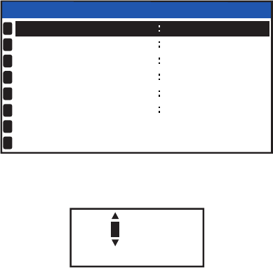
3.4.4 TX on/off log
The [TX ON/OFF LOG] shows the date and time at which transmissions were started
or stopped. The time and date at which unit was turned off is also displayed.
1. Press the MENU/ESC key to open the main menu.
2. Select [DIAGNOSTICS] then press the ENT/ACK key.
3. Select [TX ON/OFF LOG] then press the ENT/ACK key.
The reasons which may be displayed are listed in the table below, along with their
meaning.
4. Press or to move the cursor and display other log entries.
The cursor selects two lines, as shown in reverse video in the figure above. The
contents of each log entry are:
• Top line: Date and time at which transmission was turned off and reason trans-
mission was turned off.
Note: If transmission is turned off for more than 15 minutes, one of the reasons
listed below is displayed.
• Bottom line: Date and time at which transmission was turned on.
5. Press the MENU/ESC key to return to the [DIAGNOSTICS] sub-menu.
Reason Meaning
POWER OFF Transmission disabled due to unit power off.
SILENT MODE Transmission disabled due to unit operating in SI-
LENT mode.
CH MANAGEMENT COMMAND Transmission disabled due to CH INFO receive
mode.
EQUIPMENT MALFUNCTION Transmission disabled due to equipment malfunc-
tion.
INVALID CONFIGURATION Transmission disabled due to invalid settings.
Reason Meaning
"POWER OFF" Transmission ceased as the power was turned
off.
"SILENT MODE" Transmission ceased due to activation of [SI-
LENT] mode.
"CH MANAGEMENT COMMAND" Transmission ceased due to current channel
settings.
"EQUIPMENT MALFUNCTION" Transmission ceased due to equipment fault.
"INVALID CONFIGURATION" Transmission ceased due to invalid settings.
TX ON/OFF LOG
: CURSOR
: BACK
ENT
- - / - - - / - - - - - - : - - : - -
30/APL/2015 8:35:00
29/APL/2015 8:35:00
29/APL/2015 17:20:00
28/APL/2015 17:20:00
27/APL/2015 17:20:00
CH MANAGEMENT COMMAND
CH MANAGEMENT COMMAND
CH MANAGEMENT COMMAND
38/APL/2015 8:35:00
37/APL/2015 8:35:00
TX-OFF REASON
008 / 020
TIME [UTC]
TX-ON
EQUIPMENT MALFUNCTION
3. MAINTENANCE, TROUBLESHOOTING
3-7
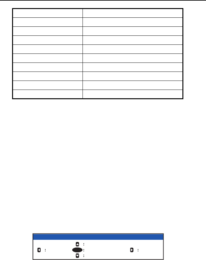
3.5 Alerts
The buzzer sounds for equipment errors and is accompanied by a flashing indication
at the bottom of the screen. Press the ENT/ACK key to silence the buzzer and ac-
knowledge the alert.
If there are multiple alerts, each alert must be acknowledged individually.
The indication at the bottom of the screen remains until the alert cause is removed or
rectified.
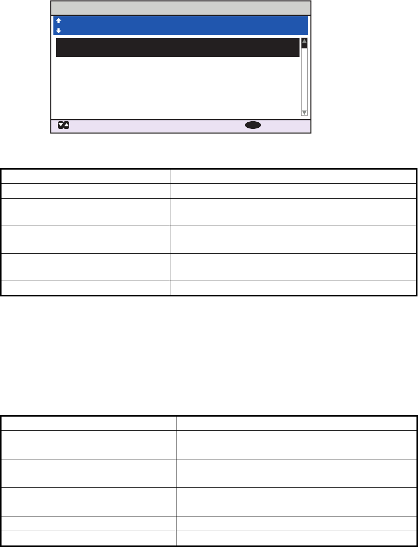
To see which alert(s) has been violated, display the [ALERT] log as shown in the pro-
cedure below.
1. Press the DISP key to show the [ALERT] log.
2. Use or to select an alert. Each alert is displayed with the date and time at
which it was generated. Where there is no date/time data available, the date/time
indication appears as “- -/- - - - -:- -”.
Select an alert to display the alert ID and brief description a box at the bottom of
the screen, as shown in the example above.
3. Press or to change the displayed tab.
The [LIST] tab shows active alerts only, in order from newest to oldest.
The [LOG] tab shows the latest 20 alerts which have been acknowledged and rec-
tified.
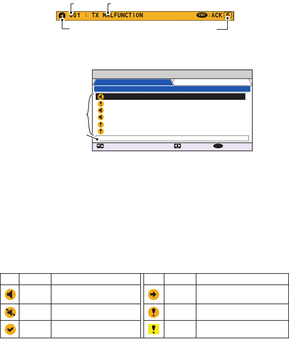
Each active alert entry is accompanied by an alert icon, indicating the state of the alert.
The alert icons displayed on the FA-170 are listed in the table below with a brief de-
scription.
See "ALERTS, IDS, MEANINGS AND MEASURES" on page AP-7 for a full list of
alerts, alert IDs, their meanings and possible counter-measures.
Alert icon
Alert code Alert message
Number of unacknowlegdge alerts
ALERT
: CURSOR
: TAB : NEXT
DISP
30/ JAN 17:20 TX MALFUNCTION
29/ JAN 17:50 ANTENNA VSWR EXCEEDS ..
28/ JAN 08:20 RX CHANNEL 1 MALFUNCTION
27/ JAN 12:35 RX CHANNEL 2 MALFUNCTION
26/ JAN 03:45 UTC SYNC INVALID
25/ JAN 09:36 ACTIVE AIS-SART
ID:001 : TX MALFUNCTION
TIME [UTC] ALERT 01 /06
LIST : 6 LOG : 20
Alert icons
Selected alert’s
alert ID and
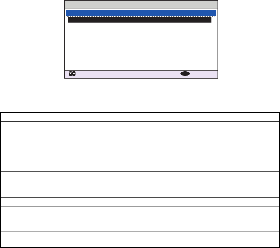
description.
Warning
Icon Priority Meaning
Active-unacknowledged
notification, icon is flashing.*
Warning Active-silenced notification,
icon is flashing.*
*: Flashing at 0.5 second intervals.
Warning Rectified-unacknowledged
notification, icon is flashing.*
Warning Active-responsibility transferred
notification, icon is lit steadily.
Warning Active-acknowledged
notification, icon is lit steadily.
Caution Active, icon is lit steadily.
Icon Priority Meaning

3. MAINTENANCE, TROUBLESHOOTING
3-8
3.6 GPS Monitor
The GPS monitor display shows information about the built-in GPS receiver, including
position, speed over ground, course over ground, date, time, mode position accuracy,
position-fixing status and RAIM status.
1. Press the MENU/ESC key to open the menu.
2. Select [STATUS], then press the ENT/ACK key.
3. Select [INTERNAL GPS], then press the ENT/ACK key.
4. Press the DISP key to close the display.
Indication Description Indication Description
UTC Date and time MODE Selected GPS mode
• [GPS]: GPS is used for position fix.
• [DGPS]: DGPS is used for position
fix.
• [NO FIX]: The system is unable to cal-
culate a position fix.
LAT Latitude of current position STATUS GPS status
• [2D]: Two dimensional GPS fix.
• [3D]: Three dimensional GPS fix.
• [D2D]: Two dimensional DGPS fix.
• [D3D]: Three dimensional DGPS fix.
• [DOP]: Dilution of precision fix.
• [NO FIX]: The system is unable to cal-
culate a position fix.
LON Longitude of current position PA Position accuracy (HIGH = Less than 10
m, LOW = more than 10m)
SOG Speed Over Ground RAIM Current RAIM status
(USED or UNUSED)
COG Course Over Ground
UTC
LAT
LON
SOG
COG
MODE
STATUS
PA
RAIM
28/NOV/2014 16:26:15
34º44.5000´N
135º21.3000´E
110.9kn
350.0º
DGPS
NO FIX
HIGH
UNUSED
INTERNAL GPS
: BACK
MENU
3. MAINTENANCE, TROUBLESHOOTING
3-9
3.7 Displaying Sensor Status
The [SENSOR STATUS] screen shows currently connected sensors’ status.
1. Press the MENU/ESC key.
2. Select [STATUS], then press the ENT/ACK key.
3. Select [SENSOR STATUS] then press the ENT/ACK key.
4. Press the DISP key to close the display. The table on the following page lists the
possible sensor status messages and their meanings.
Sensor Status Message Meaning
EXTERNAL DGNSS IN USE Using external DGNSS
EXTERNAL GNSS IN USE Using external GNSS
INTERNAL DGNSS IN USE
(BEACON)
Using internal DGNSS beacon
INTERNAL DGNSS IN USE
(MESSAGE 17)
MSG 17 corrects internal GNSS with differential correction
INTERNAL GNSS IN USE Using internal GNSS
EXTERNAL SOG/COG IN USE Using external SOG/COG
INTERNAL SOG/COG IN USE Using internal SOG/COG
HEADING VALID Heading data normal
RATE OF TURN INDICATOR IN USE ROT data normal
OTHER ROT SOURCE IN USE Value calculated from HDT, or ROT device used and talker
is other than TI.
CHANNEL MANAGEMENT
PARAMETERS CHANGED
Channel changed (displayed about 30 s)
SENSOR STATUS
: CURSOR
: BACK
MENU
01 : No. 1 EXTERNAL DGNSS IN USE
02 : No. 4 INTERNAL DGNSS IN USE (MESSAGE 17)
03 : No. 7 INTERNAL SOG / COG IN USE
04 : No. 10 OTHER ROT SOURCE IN USE
SENSOR STATUS 01 /04
3. MAINTENANCE, TROUBLESHOOTING
3-10
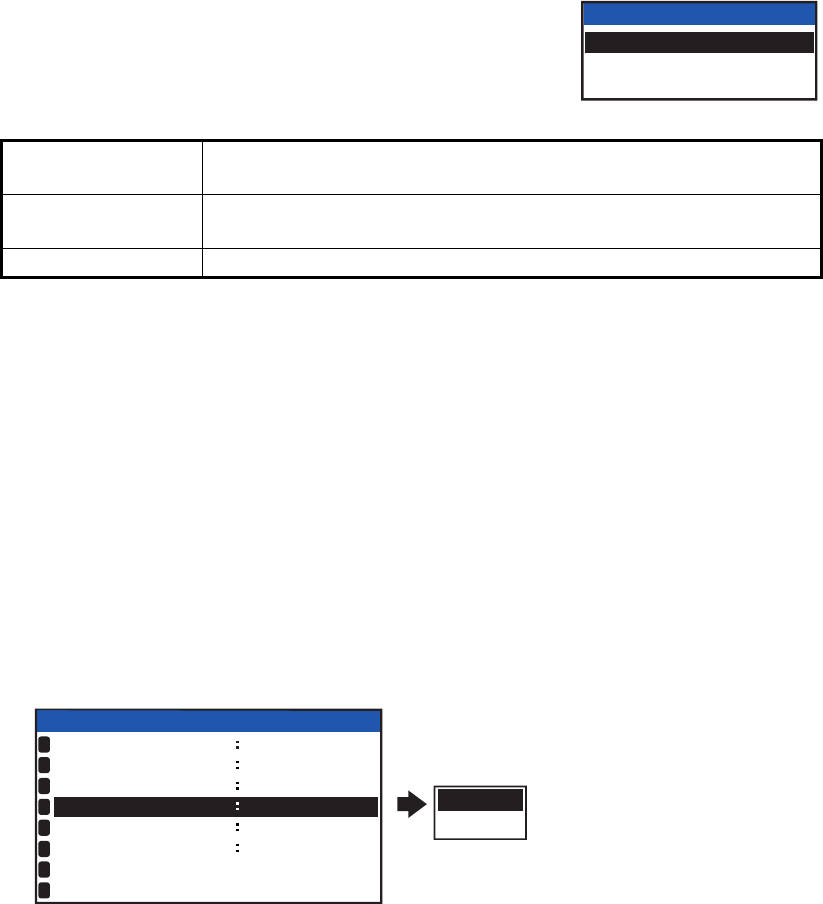
3.8 How to Restore Default Settings
You may clear all or specific settings to start afresh with default settings. When all data
is cleared, the default settings for all items in the [USER SET] menu restored, all mes-
sages and the alert history are cleared. GPS data is also cleared; however, MMSI and
IMO numbers, ship’s name and call sign are not cleared.
1. Press the MENU/ESC key to open the menu.
2. Select [DIAGNOSTICS] then press the ENT/ACK key.
3. Select [CLEAR MEMORY] then press the ENT/ACK
key.
4. Select [CLEAR ALL], [CLEAR MONITOR SET] or
[CLEAR GPS] as appropriate then press the ENT/ACK
key. A confirmation pop up window appears.
5. Select [YES] then press the ENT/ACK key.
For [CLEAR ALL] and [CLEAR MONITOR SET], a beep sounds then the equip-
ment restarts.
3.9 AIS-SART Test Indication in Target List
The FA-170 can confirm if an AIS-SART station is functioning correctly. This test re-
quires message 1 data or Message 14 data. Note that this setting is deactivated when
the power is turned off.
Note: This function tests if an AIS-SART station is functioning correctly, it is not a
SART diagnostic tool for FA-170.
1. Press the MENU/ESC key to open the menu.
2. Select [USER SET], then press the ENT/ACK key.
3. Select [SART TEST], then press the ENT/ACK key.
4. Select [SHOW], then press the ENT/ACK key.
5. Press the DISP key to close the menu.
6. Press the DISP to show the [TARGET LIST]. If the [DANGEROUS TARGET] is
displayed, switch to the [TARGET LIST], referring to step 3 of section 1.8.2.
7. Select [SART] then press the ENT/ACK key to show detailed information for the
AIS-SART station.
8. Confirm that the [STATUS] field is showing "SART TEST".
CLEAR ALL Restores all settings to default, except items in the [INITIAL SET]
menu (MMSI No., IMO No., ship’s name and call sign, etc.)
CLEAR MONITOR
SET
Restore default settings for dimmer, contrast, key beep and noti-
fications.
CLEAR GPS Clears GPS Almanac to receive latest Almanac.
CLEAR MEMORY
CLEAR ALL
CLEAR MONITOR SET
CLEAR GPS
SHOW
HIDE
USER SET
KEY BEEP
AUTO SORT
TIME DIFF
ON
HIDE
AUTO
+00 : 00
ON
SART TEST
LR RESPONSE
LR BROADCAST
NOTIFICATION SET
ACTIVATE
1
2
3
4
5
6
7
8
ON

APPENDIX 1 MENU TREE
MAIN MENU
├
1 MSG
├
2 STATUS
├
3 USER SET Bold Itali
c
: Default
├
4 INITIAL SET
├
5 CH INFO
├
6 DIAGNOSTICS
└
7 SERVICE
(
For service personnel onl
y)
1 MSG
├
NEW MSG
└
MSG BOX
├
INBOX
└
OUTBOX
2 STATUS
├
INTERNAL GPS
└
SENSOR STATUS
3 USER SET
├
KEY BEEP (ON , OFF)
├
TIME DIFF (-11:00 to +14:00, default: +00:00 )
├
A
UTO SORT
(
ON , OFF
)
├
SART TEST
(
SHOW, HID
E
)
├
LR RESPONSE
(
AUT
O
, MANUAL
)
├
LR BROADCAST
(
ON , OFF
)
├
NOTIFICATION SET
│
├
A
LERT ―BUZZER (ON , OFF)
│
├
RX MESSAGE
│
│
├
ADDRESSED (POPUP+BUZZER , POPUP, OFF)
│
│
└
BROADCAST (POPUP+BUZZER , POPUP, OFF)
│
│
│
└
COLLISION DETECT
│
└
INDICATION (POPUP+BUZZER , POPUP, OFF)
│
└
ACTIVATE
4 INITIAL SET
├
SHIP'S INFORMATION
│
├
MMSI
(
000000000 to 999999999,default: ---------
)
│
├
NAME
(
Maximum 20 characters, default: BLANK
)
│
├
IMO NO.
(
0000000000 to 1073741823
)
│
├
CALL SIGN
(
Maximum 7 characters, default: BLANK
)
│
├
TYPE OF SHIP
(
00 to 99
)
│
└
LONG RANGE
│
├
CH C
(
0075, 1075 , 0076, 1076
)
│
└
CH D
(
0075, 1075, 0076, 107
6
)
│
├
A
NTENNA POSITION
│
├
SHIP SIZE
│
│
├
LENGTH
(
0m to 800m
)
│
│
└
BEAM
(
0m to 100m
)
│
└
A
NT POSN
│
├
INTERNAL Y
(
0m to 511m
)
│
├
INTERNAL X
(
-31m to 32 m, default: 0m
)
│
├
EXTERNAL Y
(
0m to 511m
)
│
└
EXTERNAL X
(
-31m to 32m, default: 0m
)
│
Continued on following page.
Class-A Menu Tree
AP-1

APPENDIX 1 MENU TREE
├
A
LERT ENABLE
│
├
WARNING1
(
001,002,003,004,014,026,029,030
)
(
ON , OFF
)
│
└
WARNING2
(
005,007,008,009,010,011,025,032,035,BAM*
)
(
ON , OFF
)
│
├
I/O PORT
│
├
COM1
│
│
├
MODE
(
EXT DISPLA
Y
, LONG RANGE, BEACON, MONITOR, SERVICE, DISABLE
)
│
│
└
SPEED
(
57600baud, 38400baud , 4800baud
)
│
├
COM2
(
SAME AS COM 1
)
│
├
COM3
(
SAME AS COM 1
)
│
│
COM4
│
│
├
MODE (EXT DISPLAY , LONG RANGE, SENSOR, BEACON, MONITOR, SERVICE, DISABLE)
│
│
└
SPEED
(
57600baud, 38400baud , 4800baud
)
│
├
COM5
(
SAME AS COM 4
)
│
├
COM6
(
SAME AS COM 4
)
│
├
SENSOR1
│
│
├
MODE
(
SENSO
R
, DISABLE
)
│
│
└
SPEED
(
Fixed at 4800baud
)
│
├
SENSOR2
(
SAME AS SENSOR 1
)
│
└
SENSOR3
(
SAME AS SENSOR 1
)
│
├
PORT PRIORITY
│
├
1st
│
│
├
LL/SOG/COG
(
SENSOR1 , SENSOR2, SENSOR3, COM4, COM5, COM6
)
│
│
├
HDG
(
SENSOR1, SENSOR2, SENSOR3 , COM4, COM5, COM6
)
│
│
└
ROT
(
SENSOR1, SENSOR2, SENSOR3 , COM4, COM5, COM6
)
│
├
2nd
│
│
├
LL/SOG/COG
(
SENSOR1, SENSOR
2
, SENSOR3, COM4, COM5, COM6
)
│
│
├
HDG
(
SENSOR1 , SENSOR2, SENSOR3, COM4, COM5, COM6
)
│
│
└
ROT
(
SENSOR1 , SENSOR2, SENSOR3, COM4, COM5, COM6
)
│
├
3rd
│
│
├
LL/SOG/COG
(
SENSOR1, SENSOR2, SENSOR3 , COM4, COM5, COM6
)
│
│
├
HDG
(
SENSOR1, SENSOR
2
, SENSOR3, COM4, COM5, COM6
)
│
│
└
ROT
(
SENSOR1, SENSOR
2
, SENSOR3, COM4, COM5, COM6
)
│
├
4th
│
│
├
LL/SOG/COG
(
SENSOR1, SENSOR2, SENSOR3, COM
4
, COM5, COM6
)
│
│
├
HDG
(
SENSOR1, SENSOR2, SENSOR3, COM4, COM5, COM
6
)
│
│
└
ROT
(
SENSOR1, SENSOR2, SENSOR3, COM4, COM5, COM
6
)
│
├
5th
│
│
├
LL/SOG/COG
(
SENSOR1, SENSOR2, SENSOR3, COM4, COM
5
, COM6
)
│
│
├
HDG
(
SENSOR1, SENSOR2, SENSOR3, COM
4
, COM5, COM6
)
│
│
└
ROT
(
SENSOR1, SENSOR2, SENSOR3, COM
4
, COM5, COM6
)
│
└
6th
│
├
LL/SOG/COG
(
SENSOR1, SENSOR2, SENSOR3, COM4, COM5, COM
6
)
│
├
HDG
(
SENSOR1, SENSOR2, SENSOR3, COM4, COM
5
, COM6
)
│
└
ROT
(
SENSOR1, SENSOR2, SENSOR3, COM4, COM
5
, COM6
)
│
├
NETWORK
│
├
IP ADDRESS
(
000.000.000.000 to 255.255.255.255, default: 172.031.024.00
4
)
│
├
SUBNET MASK
(
000.000.000.000 to 255.255.255.255, default: 255.255.000.000
)
│
├
GATEWAY
(
000.000.000.000 to 255.255.255.255
)
│
└
SFI
(
AI0001 to AI9999
)
│
│
│
│
│
│
Continued from previous pa
g
e.
Continued on followin
g
pa
g
e.
*: Displayed only when
connected to BAMS.
AP-2

APPENDIX 1 MENU TREE
├
NETWORK
(
NAVNET
)
│
├
IP ADDRESS
(
000.000.000.000 to 255.255.255.255
,
default: 172.031.024.00
4
)
│
├
SUBNET MASK
(
000.000.000.000 to 255.255.255.255
,
default: 255.255.000.000
)
│
├
GATEWAY
(
000.000.000.000 to 255.255.255.255
)
│
├
NAVNET PORT
(
10000 to 30000
)
│
├
HOST NAME
(
AIS0 to AIS9
)
│
├
A
IS INFO
(
ON
,
OFF
)
│
├ZDA INFO
(
ON
,
OF
F
)
│
└
GPS INFO
(
ON, OF
F
)
└
EDIT
5 CH INFO
└
REGION LIST
├
A
REA
(
top ri
g
ht corner coordinates
)
│
├
LAT; default: --º --.-' -
(
current coordinates
)
│
└
LON; default: --º --.-' -
(
current coordinates
)
├
A
REA
(
bottom left corner cordinates
)
, same as top ri
g
ht coordinates.
├
ZONE
(
1 to 8, default: 5
)
└
CH
├
PWR
(
HIG
H
, LOW
)
├
CH A
(
Channel no./TXRX, RX, OFF
)
; default: 2087/TXRX .
└
CH B
(
Channel no./TXRX, RX, OFF
)
; default: 2088/TXRX .
6 DIAGNOSTICS
├
MONITOR TEST
├
TRANSPONDER TEST
├
COMMUNICATION TEST
├
TX ON/OFF LOG
└
CLEAR MEMORY
(
CLEAR ALL , CLEAR MONITOR SET, CLEAR GPS
)
7 SERVICE
(
Re
q
uires
p
assword access. For service
p
ersonnel onl
y)
Continued from previous pa
g
e.
AP-3

APPENDIX 1 MENU TREE
MAIN MENU
├
1 MSG
├
2 STATUS Bold Itali
c
: Default
├
3 USER SET
├
4 INITIAL SET
├
5 CH INFO
├
6 DIAGNOSTICS
└
7 SERVICE
(
For service personnel onl
y)
1 MSG
├
TEXT
│
├
NEW MSG
│
└
MSG BO
X
├
ETA/RT
A
│
├
NEW MSG* *: Not available in SOLAS mode.
│
└
MSG BO
X
├
NO. OF PERSONS
│
├
NEW MSG
│
└
MSG BO
X
├
EMMA WARNING BO
X
└
WATER LEVEL BO
X
2 STATUS
├
INTERNAL GPS
└
SENSOR STATUS
3 USER SET
├
KEY BEEP
(
ON , OFF
)
├
TIME DIFF
(
-11:00 to +14:00
)
, default: +00:00
├
A
UTO SORT
(
ON , OFF
)
├
SART TEST
(
SHOW, HID
E
)
├
LR RESPONSE
(
AUT
O
, MANUAL
)
├
LR BROADCAST
(
ON , OFF
)
├
NOTIFICATION SET
│
├
A
LERT ―BUZZER
(
ON , OFF
)
│
├
RX MESSAGE
│
│
├
A
DDRESSED
(
POPUP+BUZZER , POPUP, OFF
)
│
│
└
BROADCAST
(
POPUP+BUZZER , POPUP, OFF
)
│
└
COLLISION DETECT
│
└
INDICATION
(
POPUP+BUZZER , POPUP, OFF
)
└
A
CTIVATE
4 INITIAL SET
├
SHIP'S INFORMATION
│
├
│
│
│
├
NAME
(
Maximum 20 characters, default: BLANK
)
│
├
IMO NO.
(
0000000000 to 1073741823
)
│
├
CALL SIGN
(
Maximum 7 characters, default: BLANK
)
│
├
ENI
(
Maximum 8 characters, default: BLANK
)
│
├
TYPE OF SHIP
(
00 to 99
)
│
└
LONG RANGE
│
├
CH C
(
0075, 1075 , 0076, 1076
)
│
└
CH D
(
0075, 1075, 0076, 107
6
)
│
├
SPEED QUALITY
(
HIGH, LOW
)
│
├
COURSE QUALITY
(
HIGH, LOW
)
│
├
HEADING QUALITY
(
HIGH, LOW
)
│
├
BLUE SIGN
(
US
E
, UNUSE
)
│
│
│
│
Continued on followin
g
pa
g
e.
Inland Menu Tree
MMSI (000000000, 200000000 to 799999999 or 982000000 to 987999999,
default: ---------
)
AP-4

APPENDIX 1 MENU TREE
├
A
NTENNA POSITION
│
├
SHIP SIZE
│
│
├
LENGTH
(
0dm to 800dm
)
│
│
└
BEAM
(
0dm to 100dm
)
│
└
A
NT POSN
│
├
INTERNAL Y
(
0dm to 5110dm
)
│
├
INTERNAL X
(
-310dm to 302dm, default: 0dm
)
│
├
EXTERNAL Y
(
0dm to 5110dm
)
│
└
EXTERNAL X
(
-310dm to 320dm, default: 0dm
)
├
A
LERT ENABLE
│
├
WARNING1
(
001,002,003,004,014,026,029,030
)
*
│
│
(
501,502,503,504,514,526,529,530
)
**
│
└
WARNING2
(
005,007,008,009,010,011,025,032,035
)
*
│
(
505,507,508,509,510,511,525,532,535,BAM
)
**
│
├
I/O PORT
│
├
COM1
│
│
├
MODE
(
EXT DISPLA
Y
, LONG RANGE, BEACON, MONITOR, SERVICE, DISABLE
)
│
│
└
SPEED
(
57600baud, 38400baud , 4800baud
)
│
├
COM2
(
SAME AS COM 1
)
│
├
COM3
(
SAME AS COM 1
)
│
│
COM4
│
│
├
MODE (EXT DISPLAY , LONG RANGE, SENSOR, BEACON, MONITOR, SERVICE, DISABLE)
│
│
└
SPEED
(
57600baud, 38400baud , 4800baud
)
│
├
COM5
(
SAME AS COM 4
)
│
├
COM6
(
SAME AS COM 4
)
│
├
SENSOR1
│
│
├
MODE
(
SENSO
R
, DISABLE
)
│
│
└
SPEED
(
Fixed at 4800baud
)
│
├
SENSOR2
(
SAME AS SENSOR 1
)
│
└
SENSOR3
(
SAME AS SENSOR 1
)
├
PORT PRIORITY
│
├
1st
│
│
├
LL/SOG/COG
(
SENSOR1 , SENSOR2, SENSOR3, COM4, COM5, COM6
)
│
│
├
HDG
(
SENSOR1, SENSOR2, SENSOR3 , COM4, COM5, COM6
)
│
│
└
ROT
(
SENSOR1, SENSOR2, SENSOR3 , COM4, COM5, COM6
)
│
├
2nd
│
│
├
LL/SOG/COG
(
SENSOR1, SENSOR
2
, SENSOR3, COM4, COM5, COM6
)
│
│
├
HDG
(
SENSOR1 , SENSOR2, SENSOR3, COM4, COM5, COM6
)
│
│
└
ROT
(
SENSOR1 , SENSOR2, SENSOR3, COM4, COM5, COM6
)
│
├
3rd
│
│
├
LL/SOG/COG
(
SENSOR1, SENSOR2, SENSOR3 , COM4, COM5, COM6
)
│
│
├
HDG
(
SENSOR1, SENSOR
2
, SENSOR3, COM4, COM5, COM6
)
│
│
└
ROT
(
SENSOR1, SENSOR
2
, SENSOR3, COM4, COM5, COM6
)
│
├
4th
│
│
├
LL/SOG/COG
(
SENSOR1, SENSOR2, SENSOR3, COM
4
, COM5, COM6
)
│
│
├
HDG
(
SENSOR1, SENSOR2, SENSOR3, COM4, COM5, COM
6
)
│
│
└
ROT
(
SENSOR1, SENSOR2, SENSOR3, COM4, COM5, COM
6
)
│
├
5th
│
│
├
LL/SOG/COG
(
SENSOR1, SENSOR2, SENSOR3, COM4, COM
5
, COM6
)
│
│
├
HDG
(
SENSOR1, SENSOR2, SENSOR3, COM
4
, COM5, COM6
)
│
│
└
ROT
(
SENSOR1, SENSOR2, SENSOR3, COM
4
, COM5, COM6
)
│
└
6th
│
├
LL/SOG/COG
(
SENSOR1, SENSOR2, SENSOR3, COM4, COM5, COM
6
)
│
├
HDG
(
SENSOR1, SENSOR2, SENSOR3, COM4, COM
5
, COM6
)
│
└
ROT
(
SENSOR1, SENSOR2, SENSOR3, COM4, COM
5
, COM6
)
Continued from previous pa
g
e.
Continued on following page
Displayed only for
A
LERT IF2 alert
**:*: Displayed for alert modes
other than ALERT IF2.
AP-5

APPENDIX 1 MENU TREE
├
NETWORK
│
├
IP ADDRESS
(
000.000.000.000 to 255.255.255.255, default: 172.031.024.00
4
)
│
├
SUBNET MASK
(
000.000.000.000 to 255.255.255.255, default: 255.255.000.000
)
│
├
GATEWAY
(
000.000.000.000 to 255.255.255.255
)
│
└
SFI
(
AI0001 to AI9999
)
├
NETWORK
(
NAVNET
)
│
├
IP ADDRESS
(
000.000.000.000 to 255.255.255.255, default: 172.031.024.00
4
)
│
├
SUBNET MASK
(
000.000.000.000 to 255.255.255.255, default: 255.255.000.000
)
│
├
GATEWAY
(
000.000.000.000 to 255.255.255.255
)
│
├
NAVNET PORT
(
10000 to 30000
)
│
├
HOST NAME
(
AIS0 to AIS9
)
│
├
A
IS INFO
(
ON , OFF
)
│
├
ZDA INFO
(
ON, OF
F
)
│
└
GPS INFO
(
ON, OF
F
)
└
EDIT
5 CH INFO
└
REGION LIST
├
A
REA
(
top ri
g
ht corner coordinates
)
│
├
LAT; default: --º --.-' -
(
current coordinates
)
│
└
LON; default: --º --.-' -
(
current coordinates
)
├
A
REA
(
bottom left corner cordinates
)
, same as top ri
g
ht coordinates.
├
ZONE
(
1 to 8, default: 5
)
└
CH
├
PWR
(
HIG
H
, LOW
)
├
CH A
(
Channel no./TXRX, RX, OFF
)
; default: 2087/TXRX .
└
CH B
(
Channel no./TXRX, RX, OFF
)
; default: 2088/TXRX .
6 DIAGNOSTICS
├
MONITOR TEST
├
TRANSPONDER TEST
├
COMMUNICATION TEST
├
TX ON/OFF LOG
└
CLEAR MEMORY
(
CLEAR ALL , CLEAR MONITOR SET, CLEAR GPS
)
7 SERVICE
(
Re
q
uires
p
assword access. For service
p
ersonnel onl
y)
Continued from previous pa
ge
AP-6
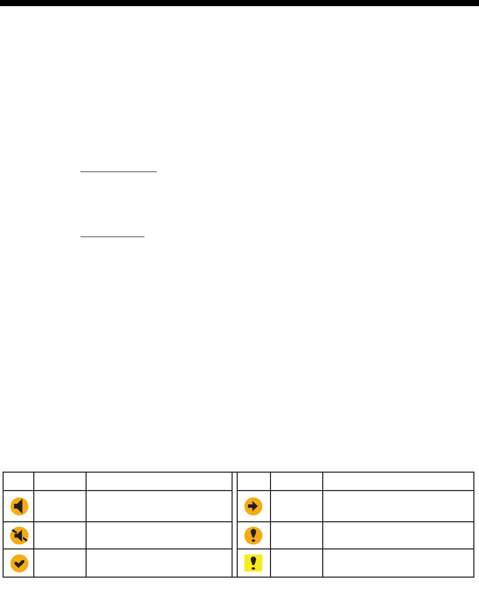
AP-7
APPENDIX 2 ALERTS, IDS, MEAN-
INGS AND MEASURES
The FA-170 displays alerts at the bottom of the screen, as they occur. You can see all alerts,
current and past, from the [ALERT LIST] screen. The ID for each alert is different, depending on
whether there is a BAM (Bridge Alert Management) system or an AMS (Alert Management
System) connected.
The table on the following page shows the alert ID, displayed message, meaning and measures
for each alert.
Note 1: Detection of RX malfunction
Note 2: Detection of TX malfunction
MPU detects TX malfunction (ID:001) in the following cases:
Each active alert entry is accompanied by an alert icon, indicating the state of the alert. The alert
icons displayed on the FA-170 are listed in the table below with a brief description.
1) Detection of TDMA RX malfunction
Frequency error
PLL chip on TRX-PWR board generates lock or unlock signal for synthesizer.
MPU watches and sets status flag which reflects data of ALR sentence.
ID 003 for RX1, ID 004 for RX2
2) Detection of DSC RX malfunction
General error
A DSC error will occur when the FA-170 cannot detect a correct signal strength from
the DSC receive circuit 120 seconds.
1) The signal indicated "LOCK" is not received from the PLL chip on the TRX-PWR
board.
2) The voltage of monitoring signal on the TRX-PWR board is abnormal. The reason
for TRX-PWR board malfunction can be a hardware problem or software problem
causing a continuous transmission that exceeds 250 msec.
Note: The hardware stops automatically because of the continuous transmission.
3) Invalid MMSI
4) An excessively high VSWR (Voltage Standing Wave Ratio) for the AIS antenna de-
tected.
Warning
Icon Priority Meaning
Active-unacknowledged
notification, icon is flashing.*
Warning Active-silenced notification,
icon is flashing.*
*: Flashing at 0.5 second intervals.
Warning Rectified-unacknowledged
notification, icon is flashing.*
Warning Active-responsibility transferred
notification, icon is lit steadily.
Warning Active-acknowledged
notification, icon is lit steadily.
Caution Active, icon is lit steadily.
Icon Priority Meaning

APPENDIX 2 ALERTS, IDS, MEANINGS AND MEASURES
AP-8
Alert ID Displayed message Meaning Measures
(BAM ID)
001
(501)
TX MALFUNCTION Transmission stopped due to
a failure.
Check antenna and FA-170
connections.
Check that the Own Ship
MMSI is set.
Consult your dealer if the
problem is not rectified.
002
(502)
LEGACY/ALERT IF1:
ANTENNA VSWR EX-
CEEDS LIMIT
ALERT IF2: ANTENNA
MALFUNCTION
High VSWR for the AIS an-
tenna detected.
Check the antenna. Consult
your dealer if the problem is
not rectified.
003
(503)
RX CHANNEL 1 MAL-
FUNCTION
RX1 failure. Circuit board may be dam-
aged. Contact your dealer.
004
(504)
RX CHANNEL 2 MAL-
FUNCTION
RX2 failure.
005
(505) *1
RX CHANNEL 70 MAL-
FUNCTION
Failed to receive DSC mes-
sage.
007
(507) *1
UTC SYNC INVALID No synchronization with
UTC.
Internal GPS has no fix.
Check weather and surround-
ing for obstacles. If the error
appears frequently, contact
your dealer.t
008
(508) *1
MKD CONNECTION
LOST
Communication failure be-
tween the transponder and
the monitor unit.
Check connection between
units. Consult your dealer if
the problem is not rectified.
009
(509) *1
INT/EXT GNSS POSI-
TION MISMATCH
Mismatch of position data
between internal GNSS and
external GNSS. After taking
into account the antenna
position, there is a difference
of over 100 m.
Check calibration and
location setting for both GPS
antennas.
010
(510) *1
NAV STATUS INCOR-
RECT
Mismatch between ship’s
speed and [NAVSTATUS]
information.
Check [NAV STATUS] menu
settings. Adjust settings
appropriately.
011
(511)*1
LEGACY/ALERT IF1:
HEADING SENSOR
OFFSET
ALERT IF2: MIS-
MATCH BETWEEN
HDG AND COG
Mismatch between COG and
HDT. There is a difference of
over 45° for more than five
minutes at a speed of over
five knots.
Check connection to sensor.
014
(514)
ACTIVE AIS-SART AIS-SART message
received
Check the message.
025
(525)
EXTERNAL EPFS
LOST
Signal from external
navigational aids lost or
interrupted.
Check connection to EPFS
devices.

APPENDIX 2 ALERTS, IDS, MEANINGS AND MEASURES
AP-9
Note 1: The Alert IDs listed in parentheses are output when the FA-170 is connected to a BAM
(Bridge Alert Management) system.
Note 2: Alert ID 600950 is only output when a BAM (Bridge Alert Management) is connected and
is given “Caution” priority level.
Note 3: Where the [ALERT MODE] is set to [Legacy Ed.1/Ed.2], alert priority level for all alerts is
fixed at “Warning”.
Note 4: Where the [ALERT MODE] is set to [ALERT IF1] or [ALERT IF2] the alerts shown with “*1”
in the table above are assigned “Caution” priority level.
026
(526)
NO POSITION SEN-
SOR IN USE
No position data available. Check connection to sensor.
029
(529)
NO VALID SOG IN-
FORMATION
SOG information is invalid.
030
(530)
NO VALID COG IN-
FORMATION
COG information is invalid.
032
(532) *1
HEADING LOST / IN-
VALID
HDG information is lost or
invalid.
035
(535) *1
NO VALID ROT INFOR-
MATION
No ROT information
available.
600950 BAM COM ERROR Communication failure
between the BAMS and the
transponder unit.
Check connection between
unit and BAM.
Alert ID Displayed message Meaning Measures
(BAM ID)
AP-10
APPENDIX 3 PARTS LIST/LOCATION
Parts List
This equipment contains complex modules in which fault diagnosis and repair down to component
level are not practical (IMO A.694(17)/8.3.1). Only some discrete components are used. FURUNO
Electric Co., Ltd. believes identifying these components is of no value for shipboard maintenance;
therefore, they are not listed in the manual. Major modules can be located on the parts location
photo on the following pages.
Parts Location
Monitor Unit
Transponder unit
Model FA-170
Unit
MONITOR UNIT,
TRANSPONDER UNIT
ELECTRICAL PARTS LIST
Blk.No.
TYPE, NAME LOCATION
PRINTED CIRCUIT BOARD
F U R U N O
20P8200D, MAIN
05P0894, C-IF
05P0893, TRX-PWR
05P0891, T-IF
20P8211, GPS
05P0892, R-MOD
MONITOR UNIT FA-1702
MONITOR UNIT FA-1702
TRANSPONDER UNIT FA-1701
TRANSPONDER UNIT FA-1701
TRANSPONDER UNIT FA-1701
TRANSPONDER UNIT FA-1701
Remove the C-IF board, then remove the grounding plate to expose the main board.
C-IF board
(05P0894)
C-IF board
(05P0894)
Grounding
plate
Grounding
plate
MAIN board
(20P8200D)
TRX-PWR
board
05P0893
TRX-PWR
board
05P0893
T-IF board
05P0891
T-IF board
05P0891
GPS board 20P8211GPS board 20P8211
R-MOD board
05P0892
R-MOD board
05P0892 Bottom layer
Middle layer
Top layer

AP-11
APPENDIX 4 CHANNEL LISTS AND
ERI CODES
International mode VHF channel list
USA mode VHF channel list
Note: 1 W power on CH13 and CH67.
Ch No.
1001
1002
1003
1004
1005
6
1007
1018
1019
1020
1021
1022
1023
1024
1025
1026
1027
1028
1060
1061
1062
1063
1064
1065
1066
67
68
69
70
71
72
73
74
75
76
77
1078
1079
1080
1081
1082
1083
1084
1085
1086
1087
Ch No.
1088
Freq.
156.05
156.1
156.15
156.2
156.25
156.3
156.35
156.9
156.95
157
157.05
157.1
157.15
157.2
157.25
157.3
157.35
157.4
156.025
156.075
156.125
156.175
156.225
156.275
156.325
156.375
156.425
156.475
156.525
156.575
156.625
156.675
156.725
156.775
156.825
156.875
156.925
156.975
157.025
157.075
157.125
157.175
157.225
157.275
157.325
157.375
Freq.
157.425
Ch No. Freq.
160.65
160.7
160.75
160.8
160.85
160.95
156.4
156.45
156.5
156.55
156.6
156.65
156.7
156.75
156.8
156.85
161.5
161.55
161.6
161.65
161.7
161.75
161.8
161.85
161.9
161.95
162
160.625
160.675
160.725
160.775
160.825
160.875
160.925
161.525
Ch No. Freq.
161.575
161.625
161.675
161.725
161.775
161.825
161.875
161.925
161.975
162.025
2001
2002
2003
2004
2005
2007
8
9
10
11
12
13
14
15
16
17
2018
2019
2020
2021
2022
2023
2024
2025
2026
2027
2028
2060
2061
2062
2063
2064
2065
2066
2078
2079
2080
2081
2082
2083
2084
2085
2086
2087
2088
Ch No.
1001
1003
1005
6
1007
1018
1019
1020
1021
1022
1023
1024
1025
1026
1027
1028
1061
1063
1064
1065
1066
67
68
69
70
71
72
73
74
75
76
77
1078
1079
1080
1081
1082
1083
1084
1085
1086
1087
Ch No.
1088
Freq.
156.05
156.15
156.25
156.3
156.35
156.9
156.95
157
157.05
157.1
157.15
157.2
157.25
157.3
157.35
157.4
156.075
156.175
156.225
156.275
156.325
156.375
156.425
156.475
156.525
156.575
156.625
156.675
156.725
156.775
156.825
156.875
156.925
156.975
157.025
157.075
157.125
157.175
157.225
157.275
157.325
157.375
Freq.
157.425
Ch No. Freq.
160.65
160.7
160.75
160.8
160.85
160.95
156.4
156.45
156.5
156.55
156.6
156.65
156.7
156.75
156.8
156.85
161.5
161.55
161.6
161.65
161.7
161.75
161.8
161.85
161.9
161.95
162
160.625
160.675
160.725
160.775
160.825
160.875
160.925
161.525
Ch No. Freq.
161.575
161.625
161.675
161.725
161.775
161.825
161.875
161.925
161.975
162.025
2001
2002
2003
2004
2005
2007
8
9
10
11
12
13
14
15
16
17
2018
2019
2020
2021
2022
2023
2024
2025
2026
2027
2028
2060
2061
2062
2063
2064
2065
2066
2078
2079
2080
2081
2082
2083
2084
2085
2086
2087
2088

APPENDIX 4 CHANNEL LISTS AND ERI CODES
AP-12
ERI Codes
Note: ERI codes 8070, 8440 and 8460 are displayed in abbreviated format.
8000
ERI code
U
No
V
V
V
V
V
V
V
V
V
V
V
V
V
V
C
C
C
C
C
C
C
C
C
C
C
C
C
C
C
C
C
C
C
C
C
C
C
C
V
V
V
V
V
V
V
V
V
V
V
V
V
V
V
V
V
V
V
V
No
C
C
C
C
C
No
No
AIS code
First
digit
Second
digit
Ship name (EN)
VESSEL., TYPE UNKNOWN
MOTOR FREIGHTER
MOTOR TANKER
MOTOR TANKER, LIQUID CARGO, TYPE N
MOTOR TANKER, LIQUID CARGO, TYPE C
MOTOR TANKER, DRY CARGO AS IF LIQUID (E.G. CEMENT)
CONTAINER VESSEL
GAS TANKER
MOTOR FREIGHTER, TUG
MOTOR FREIGHTER WITH ONE OR MORE SHIPS ALONGSIDE
MOTOR FREIGHTER WITH TANKER
MOTOR FREIGHTER PUSHING ONE OR MORE FREIGHTERS
MOTOR FREIGHTER PUSHING AT LEAST ONE TANK-SHIP
TUG, FREIGHTER
TUG, FREIGHTER, COUPLED
TUG, FREIGHTER/TANKER, COUPLED
FREIGHTBARGE
FREIGHTBARGE WITH CONTAINERS
TANKBARGE
TANKBARGE, GAS
PUSHTOW, ONE CARGO BARGE
PUSHTOW, TWO CARGO BARGES
PUSHTOW, THREE CARGO BARGES
PUSHTOW, FOUR CARGO BARGES
PUSHTOW, FIVE CARGO BARGES
PUSHTOW, SIX CARGO BARGES
PUSHTOW, SEVEN CARGO BARGES
PUSHTOW, EIGHT CARGO BARGES
PUSHTOW, NINE CARGO BARGES
PUSHTOW, ONE TANK/GAS BARGE
PUSHTOW, 2 BARGES AT LEAST ONE TANKER/GAS BARGE
PUSHTOW, 3 BARGES AT LEAST ONE TANKER/GAS BARGE
PUSHTOW, 4 BARGES AT LEAST ONE TANKER/GAS BARGE
PUSHTOW, 5 BARGES AT LEAST ONE TANKER/GAS BARGE
PUSHTOW, 6 BARGES AT LEAST ONE TANKER/GAS BARGE
PUSHTOW, 7 BARGES AT LEAST ONE TANKER/GAS BARGE
PUSHTOW, 8 BARGES AT LEAST ONE TANKER/GAS BARGE
PUSHTOW, 9 OR MORE BARGES AT LEAST ONE TANKER/GAS BARGE
TUG, SINGLE
TUG, ONE OR MORE TOWS
TUG, ASSISTING A VESSEL OR LINKED COMBINATION
PUSHBOAT, SINGLE
PASSENGER SHIP, FERRY, CRUISE SHIP, RED CROSS SHIP
FERRY
RED CROSS SHIP
CRUISE SHIP
PASSENGER SHIP WITHOUT ACCOMMODATION
SERVICE VESSEL, POLICE PATROL, PORT SERVICE
OBJECT, TOWED, NOT OTHERWISE SPECIFIED
FISHING BOAT
BUNKERSHIP
BARGE, TANKER, CHEMICAL
OBJECT, NOT OTHERWISE SPECIFIED
GENERAL CARGO VESSEL MARITIME
UNIT CARRIER MARITIME
BULK CARRIER MARITIME
TANKER
LIQUIFIED GAS TANKER
PLEASURE CRAFT, LONGER THAN 20 METRES
FAST SHIP
HYDROFOIL
VESSEL, WORK MAINTENANCE CRAFT, FLOATING DERRICK,
CABLE SHIP, BUOY SHIP, DREDGE
TANKBARGE, LIQUID CARGO, TYPE N
TANKBARGE, LIQUID CARGO, TYPE C
TANKBARGE, DRY CARGO AS IF LIQUID (E.G. CEMENT)
TUG, TANKER
MOTOR TANKER, TUG
Full
code
8010
8020
8021
8022
8023
8030
8040
8050
8060
8070
8080
8090
8100
8110
8120
8130
8140
8150
8160
8161
8162
8163
8170
8180
8210
8220
8230
8240
8250
8260
8270
8280
8290
8310
8320
8330
8340
8350
8360
8370
8380
8390
8400
8410
8420
8430
8440
8441
8442
8443
8444
8450
8460
8470
8480
8490
8500
8510
1500
1510
1520
1530
1540
1850
1900
1910
9 9
9 9
9 9
9 9
9 0
9 0
9 0
8 0
8 0
8 0
8 0
8 0
8 0
8 0
8 0
8 0
5 2
3 1
3 1
9 9
9 9
9 9
9 9
8 0
9 9
7 9
7 9
7 9
8 0
8 0
3 7
4 9
4 9
3 0
3 3
6 9
6 9
6 9
6 9
5 8
7 9
7 9
7 9
7 9
8 9
8 9
8 9
8 9
7 9
7 9
7 9
7 9
7 9
7 9
7 9
7 9
7 9
7 9
7 9
8 9
8 9
8 9
3 1
3 1
8 0
8 0
8 0

AP-13
APPENDIX 5 ABBREVIATIONS, UNITS
AND SYMBOLS
Numerical abbreviations
A:
B:
C:
D:
Abbreviation Meaning Abbreviation Meaning
2D Two Dimensional Positioning 3rd Third
3D Three Dimensional Positioning 4th Fourth
1st First 5th Fifth
2nd Second 6th Sixth
Abbreviation Meaning Abbreviation Meaning
ACK Acknowledge ANT Antenna
AGE Time elapsed from acquisition. APR April
AIS Automatic Identification
System
AtoN Aids to Navigation
AUG August
ALARM Alarm AUTO Automatic
ALT Altitude
Abbreviation Meaning Abbreviation Meaning
BAM Bridge Alert Management BRG Bearing
BASE Base Station BRILL Brilliance
baud Baud rate BS Beam of ship, Back Space, Base
Station
BC Beam of convoy
Abbreviation Meaning Abbreviation Meaning
CH Channel CONT Contrast
COG Course Over the Ground CPU Central Processing Unit
COM, COMM Communication
Abbreviation Meaning Abbreviation Meaning
D2D Differential and 2D DGNSS Differential GNSS
D3D Differential and 3D DGPS Differential GPS
DATE Date DIFF Difference
DAY Day DISP Display
DEC December DNGR Danger
DEL Delete DOP Dilution Of Precision
DEST Destination DPTH Depth
DG Dangerous Goods DSC Digital Selective Calling

APPENDIX 5 ABBREVIATIONS, UNITS AND SYMBOLS
AP-14
E:
F:
G:
H:
I:
J:
Abbreviation Meaning Abbreviation Meaning
E East ENI Unique European Vessel
Identification Number
EA Extension A ENT Enter
EB Extension B EPIRB Emergency Position Indicating Ra-
dio Beacon
EC Extension C EPFS Electronic Position Fixing
System
ECDIS Electronic Chart Display
Information System
EMMA European Multiservice
Meteorological Awareness
system
ERI Electronic Reporting International
(ship type) code
ESC Escape
ETA Estimated Time of Arrival
EXT External
Abbreviation Meaning Abbreviation Meaning
FEB February FL Flood
FI Fire in the forests FO Fog
FIX Fix FUNC FUNCTION
Abbreviation Meaning Abbreviation Meaning
GNSS Global Navigation Satellite
System
GPS Global Positioning System
Abbreviation Meaning Abbreviation Meaning
H Height HI High
HDG Heading HS Harmful Substances
(applies to AIS)
HDT Data sentence (Heading-true)
HECT Hectometer HSC High Speed Craft
Abbreviation Meaning Abbreviation Meaning
ID Identification INFO Information
IEC International Electrotechnical
Commission
INT Internal
IF Interface I/O Input/Output
IFM International Function
Message
IP Internet Protocol (Address)
IMO International Maritime
Organization
ISO International Standards
Organization
Abbreviation Meaning Abbreviation Meaning
JAN January JUN June
JUL July

APPENDIX 5 ABBREVIATIONS, UNITS AND SYMBOLS
AP-15
L:
M:
N:
O:
P:
Abbreviation Meaning Abbreviation Meaning
L Low, left LO Low
LAN Local Area Network LOG Log
LAT Latitude LON Longitude
LC Length of convoy LR Long Range
LCD Liquid Crystal Display LS Length of ship
L/L Latitude/Longitude LT Local Time
LL Latitude/Longitude
Abbreviation Meaning Abbreviation Meaning
MAR March MMSI Maritime Mobile Services
Identity number
MAX Maximum MP Maritime Pollutant
(applies to AIS)
MAY May
MENU Menu MPU Micro processing Unit
MIN Minimum MSG Message
MKD Minimum Keyboard Display MOB Man Overboard
Abbreviation Meaning Abbreviation Meaning
N North NIGHT Night
NAME Name NG No Good
NAV Navigation NO. Number
NAV STATUS Navigational status NOV November
NE Northeast NW Northwest
Abbreviation Meaning Abbreviation Meaning
OCT October ON On
OFF Off OS Other Substances, Own Ship
OK O.K.
Abbreviation Meaning Abbreviation Meaning
PA Position Accuracy PORT Port
PI Position Indicator POSN Position
PLL Phase Locked Loop PWR Power

APPENDIX 5 ABBREVIATIONS, UNITS AND SYMBOLS
AP-16
R:
S:
T:
U:
V:
W:
Abbreviation Meaning Abbreviation Meaning
RA Rain ROM Read Only Memory
RAIM Receiver Autonomous
Integrity Monitoring
ROM(M) ROM (Monitor Unit)
ROM(T) ROM (Transponder Unit)
RAIN Rain ROT Rate Of Turn
RAM Random Access Memory RSSI Received Signal Strength
Indication
RAM(M) RAM (Monitor Unit)
RAM(T) RAM (Transponder Unit) RTA Requested Time of Arrival
RFM Regional Function Message RX Receive
RNG Range
Abbreviation Meaning Abbreviation Meaning
S South SFI System Function ID
SAR Search And Rescue SIM Simulation
SART Search And Rescue
Transponder
SN Snow and Ice
SART ACT. SART active SOG Speed Over the Ground
SE Southeast SOLAS Safety Of Life At Sea
SEP September STW Speed Through the Water
SET Set (i.e., set and drift, or setting
a value)
SW Southwest, Switch
SYNC Synchronization
Abbreviation Meaning Abbreviation Meaning
TEST Test TOW Vessel engaged in towing oper-
ations
TH Thunderstorm TRANS Transition
TI Turn rate Indicator TRX Transceiver
TIME Time TX Transmit
Abbreviation Meaning Abbreviation Meaning
UN/
LOADED
LOADED or UNLOADED UTC Universal Coordinated Time
Abbreviation Meaning Abbreviation Meaning
VHF Very High Frequency VSWR Voltage Standing Wave Ratio
Abbreviation Meaning Abbreviation Meaning
W West, Wide WI Wind
WARNING Warning WIG Wing In Ground
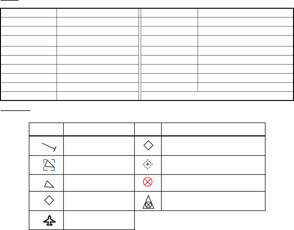
APPENDIX 5 ABBREVIATIONS, UNITS AND SYMBOLS
AP-17
Units
Symbols
Abbreviation Unit Abbreviation Unit
° degree(s) kn knot(s)
°C degree(s) kbps kilo bit per second
bps bit per second l/m2hliter per square meter hour
cm centimeter m meter
cm/h centimeter per hour min minute(s)
dm decimeter msec millisecond
hr Hour(s) NM nautical mile(s)
km kilometer s second(s)
km/h kilometer per hour
Own ship symbol
Symbol Description Symbol Description
Selected target
Unselected target
AIS AtoN (virtual)
AIS SART/AIS MOB/EPIRB AIS
SAR aicraft
SAR vessel
BAIS Base Station
AIS AtoN (physical)
FURUNO
FA-170
SP - 1 E4490S01F
151021
SPECIFICATIONS OF U-AIS TRANSPONDER
FA-170
1 TRANSPONDER UNIT
1.1 TX/RX frequency 156.025 MHz to 162.025 MHz
1.2 Output power 1 W or 12.5 W selectable
1.3 Impedance 50 ohms
1.4 DSC receiver CH70 fixed, 156.525 MHz
1.5 Bandwidth 25 kHz
2 MONITOR UNIT
2.1 Screen 4.3-inch color LCD, 480 x 272 dots (WQVGA)
2.2 Brilliance control 18 steps
2.3 Visible distance 0.7 m nominal
2.4 Buzzer volume 75 to 85 dB (A)
3 GPS RECEIVER
3.1 Receiving frequency 1575.42 MHz
3.2 Tracking code C/A code
3.3 Number of channel 12 channels parallel, 12 satellites
3.4 Accuracy (dependent on ionospheric activity and multipath)
GPS 13 m max. (2drms、HDOP < 4)
DGPS 5 m max. (2drms、HDOP < 4)
3.5 Tracking speed 1000 kn
3.6 Position fixing time Warm start: 12 s, Cold start: 90 s
3.7 Position update interval 1 second typical
3.8 DGPS data receiving RTCM SC-104 ver-2.1
4 INTERFACE
4.1 Number of ports
Serial 6 ports, IEC61162-1 Ed.4 or IEC61162-2 Ed.1
Sensor input 3 port, IEC61162-1 Ed.4, 4800 bps
Alarm I/O 1 port, Contact closure (normal close or open)
LAN 1 port, Ethernet, 100Base-TX, RJ45 connector, Auto MDI/MDIX,
for IEC61162-450 Ed.1
BLUESIGN input 1 port, Relay contact
4.2 Data sentences IEC61162-1/2
Input ABM, ACA, ACK, ACM, ACN, AIQ, AIR, BBM, DTM, EPV, GBS,
GGA, GLL, GNS, HBT, HDT, LRF, LRI, OSD, PIWWIVD,
PIWWSPW, PIWWSSD, PIWWVSD, RMC, ROT, SPW, SSD, THS,
VBW, VSD, VTG
Output ABK, ACA, ACS, ALC, ALF, ALR, ARC, EPV, HBT, LR1, LR2, LR3,
LRF, LRI, NAK, PIWWIVD, PIWWSPR, PIWWSSD, PIWWVSD,
SSD, TRL, TXT, VER, VDM, VDO, VSD
FURUNO
FA-170
SP - 2 E4490S01F
151021
4.3 Proprietary sentences (output only)
PFEC LBK, AIcmd, idatr, ident, idfnc, pidat, pireq
4.4 IEC61162-450 transmission group
Input MISC, TGTD, SATD, NAVD, PROP
Output Arbitrary (default: TGTD)
4.5 Network function (except IEC61162-450)
Data format SNMP, HTTP, Syslog, Furuno Management Protocol (FMP)
Data sentences same as 4.2 sentences
5 POWER SUPPLY
3.1 Transponder unit 12-24 VDC: 6-3 A
3.2 Monitor unit 12 VDC: 0.3 A max. (supplied from transponder unit)
3.3 AC/DC power supply unit (PR-240, option)
100-115/200-230 VAC, 1 phase, 50/60 Hz
6 ENVIRONMENTAL CONDITIONS
6.1 Ambient temperature
GPS/VHF antenna -30°C to +70°C (storage: -30°C to +85°C)
Other units -15°C to +55°C
6.2 Relative humidity 93% or less at +40°C
6.3 Degree of protection
GPS/VHF antenna IP56
Transponder unit IP20, IP22 (bulkhead mount)
Monitor unit IP22, IP35 (option)
Pilot plug unit IP22 (front panel), IPX0 (chassis)
6.4 Vibration IEC 60945 Ed.4
7 UNIT COLOR
7.1 GPS/VHF antenna N9.5
7.2 Transponder/ Monitor unit N2.5
7.3 Pilot plug unit N2.5

IN-1
INDEX
A
AIS-SART test indication .........................3-10
ALERT display .........................................1-19
ALERT LIST...............................................3-7
ALERT LOG...............................................3-7
Alert status .................................................3-7
C
Channels
setting.....................................................1-25
viewing ...................................................1-24
Contrast .....................................................1-3
Controls......................................................1-1
D
Dangerous (target) list ................... 1-15, 2-11
Default settings ........................................3-10
Diagnostics
monitor unit test........................................3-3
TX on/off log.............................................3-6
VHF communication test..........................3-5
Dimmer ......................................................1-3
DISP key ..................................................1-11
Display
icons.........................................................1-4
key guidance............................................1-4
status bar .................................................1-4
E
EMMA warning message (inland AIS) .....2-21
ETA message (inland AIS).......................2-16
F
Fuse replacement ......................................3-2
G
GPS monitor ..............................................3-8
I
Initial settings
class A....................................................1-31
inland AIS...............................................2-23
Inland AIS
activating..................................................2-1
EMMA warning message .......................2-21
ETA message.........................................2-17
mode selection.........................................2-2
no. of persons message.........................2-20
RTA message ........................................2-19
static data.................................................2-8
text message..........................................2-14
time difference setting.................. 1-32, 2-24
voyage-related data entry ........................2-3
water level message ..............................2-22
K
Key beep
on/off ......................................................1-28
L
Long range mode.....................................1-28
M
Maintenance ..............................................3-1
Memory clear ...........................................3-10
Menu
enterring alphanumeric data ....................1-6
selecting an option ...................................1-6
MENU key..................................................1-5
Messages
EMMA warning (inland AIS)...................2-21
ETA (inland AIS) ....................................2-17
receive text, class A ...............................1-22
received message pop up window .........1-22
RTA (inland AIS) ....................................2-19
send text message, class A ...................1-20
water level (inland AIS) ..........................2-22
Monitor unit test .........................................3-3
N
NAV STATUS
enterring voyage-related data ..................1-7
NAV STATUS key.............................. 1-7, 2-3
No. of persons message (inland AIS) ......2-20
Notifications .............................................1-10
alert buzzer ............................................1-10
collision detection...................................1-10
received messages ................................1-10
P
Plotter display ..........................................1-12
Power on/off...............................................1-2
R
RTA message (inland AIS).......................2-19
S
Sensor status .............................................3-9
Static data display....................................1-18
System overview.......................................... iii
T
Target list ......................................... 1-14, 2-9
Troubleshooting .........................................3-2