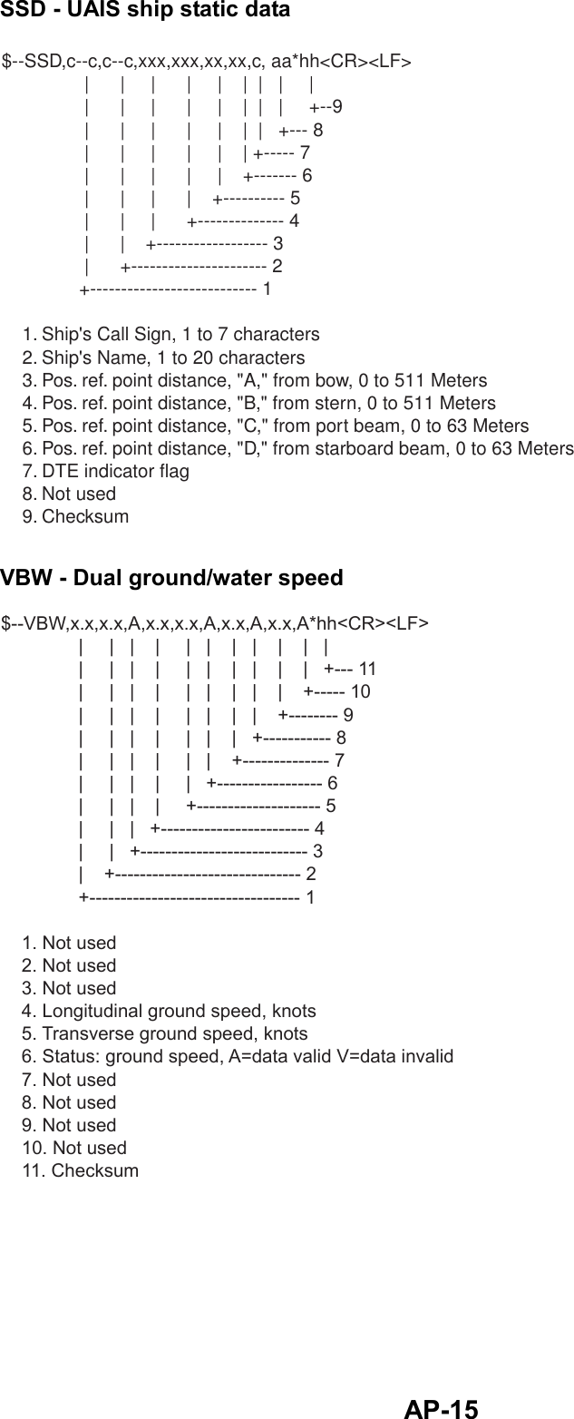
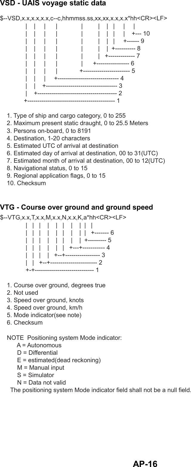
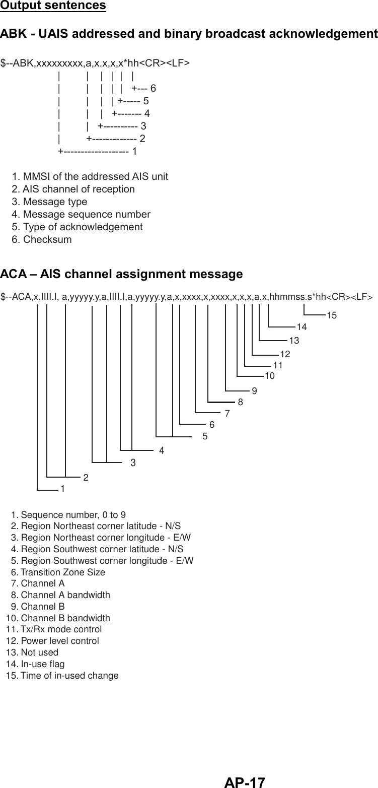
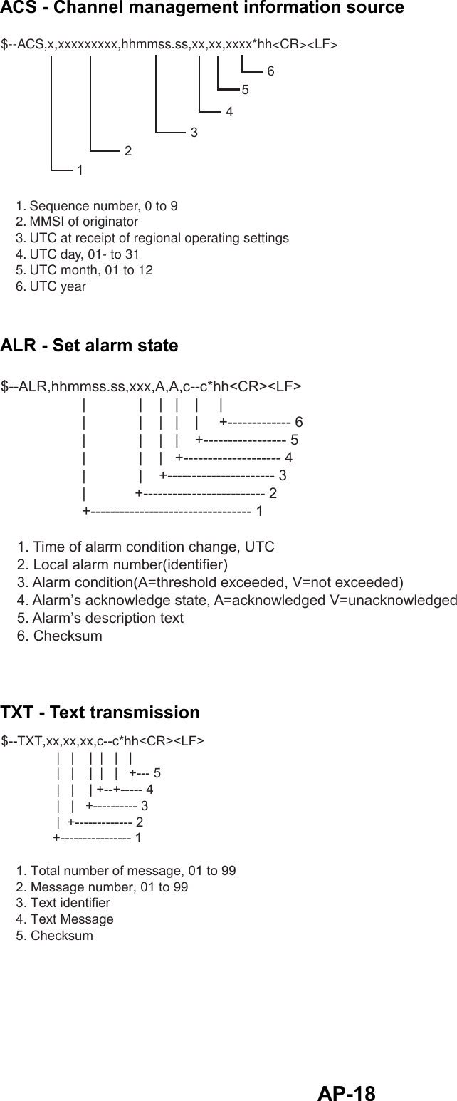
Furuno USA 9ZWFA50 Automatic Identification System User Manual PL
Furuno USA Inc Automatic Identification System PL
UserManual.wiki
>
Furuno USA
>
9ZWFA50 User Manual
>
Operators Manual
Contents
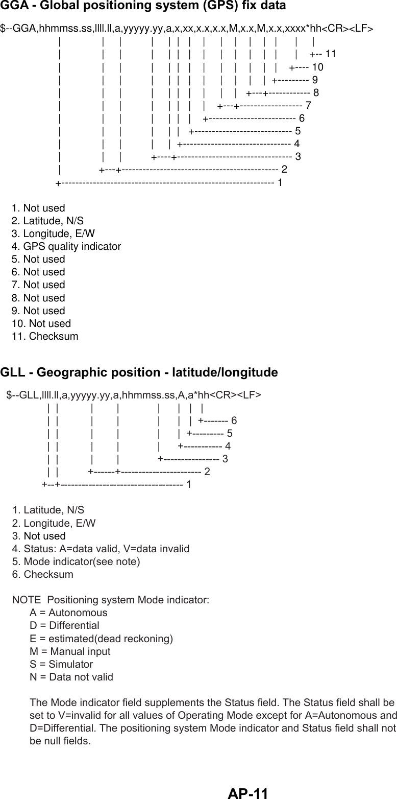
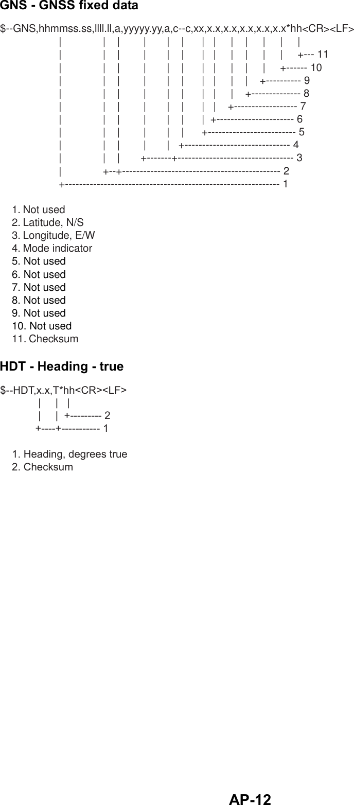
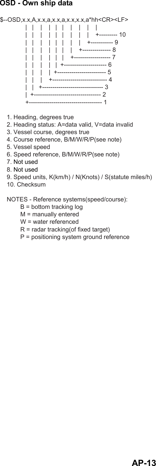
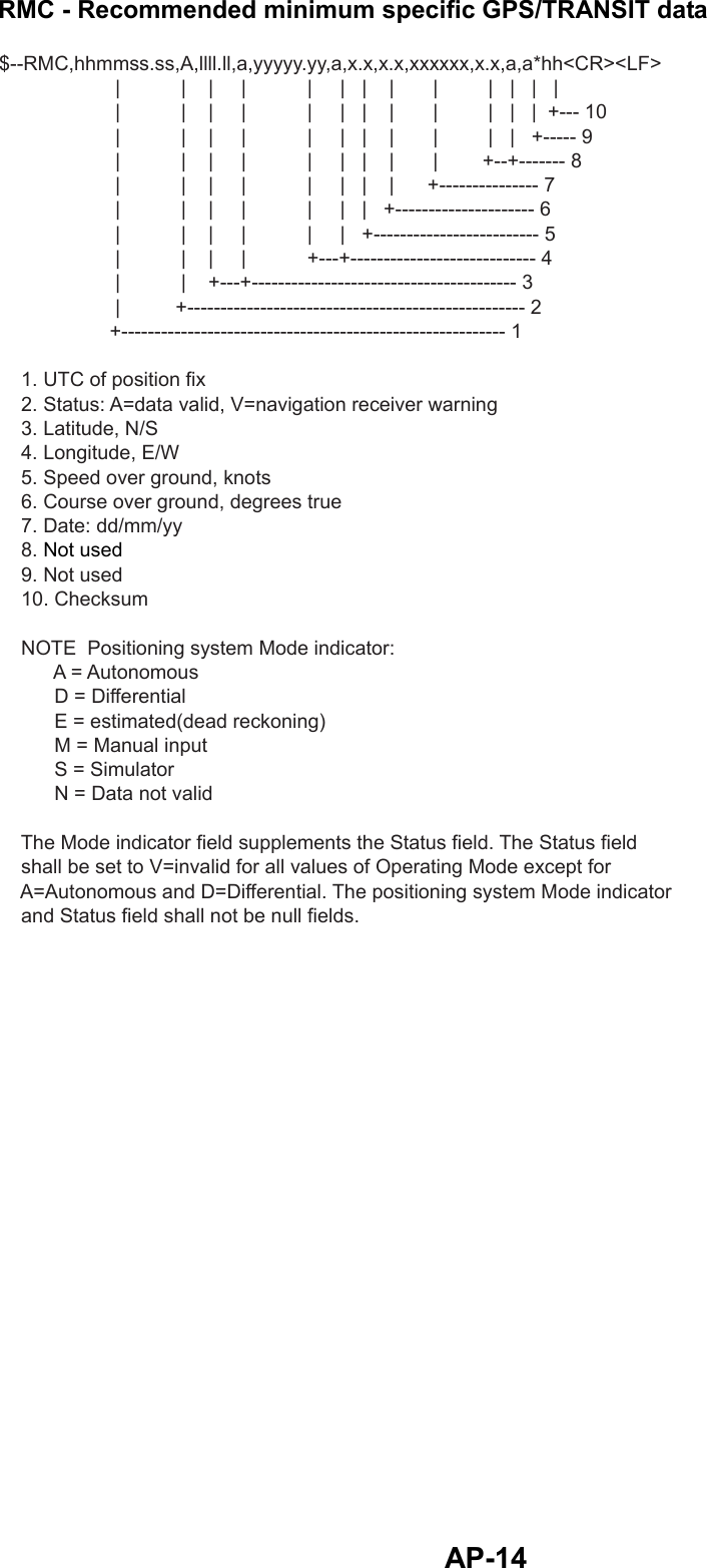
1.
Operators Manual
2.
operation manual
Operators Manual
Navigation menu
Upload a User Manual
Namespaces
Wiki Guide
HTML
PDF
Info
Views
User Manual
Discussion / Help
Navigation