Furuno USA 9ZWFA50 Automatic Identification System User Manual
Furuno USA Inc Automatic Identification System
UserManual.wiki
>
Furuno USA
>
9ZWFA50 User Manual
>
operation manual
Contents
1.
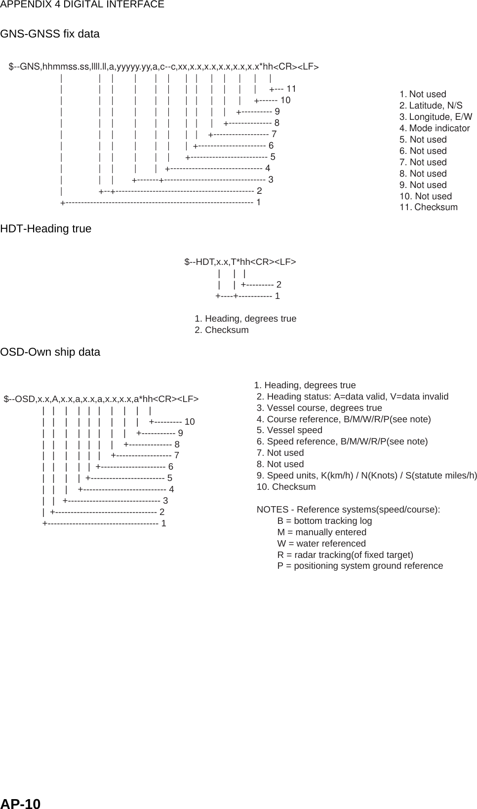
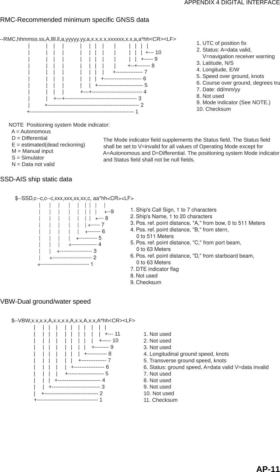
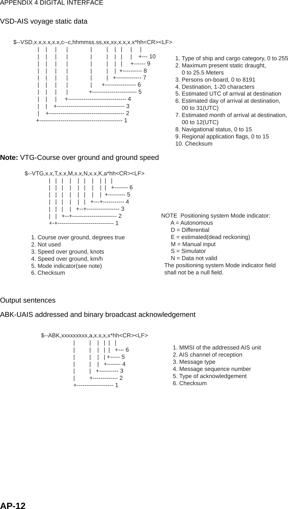
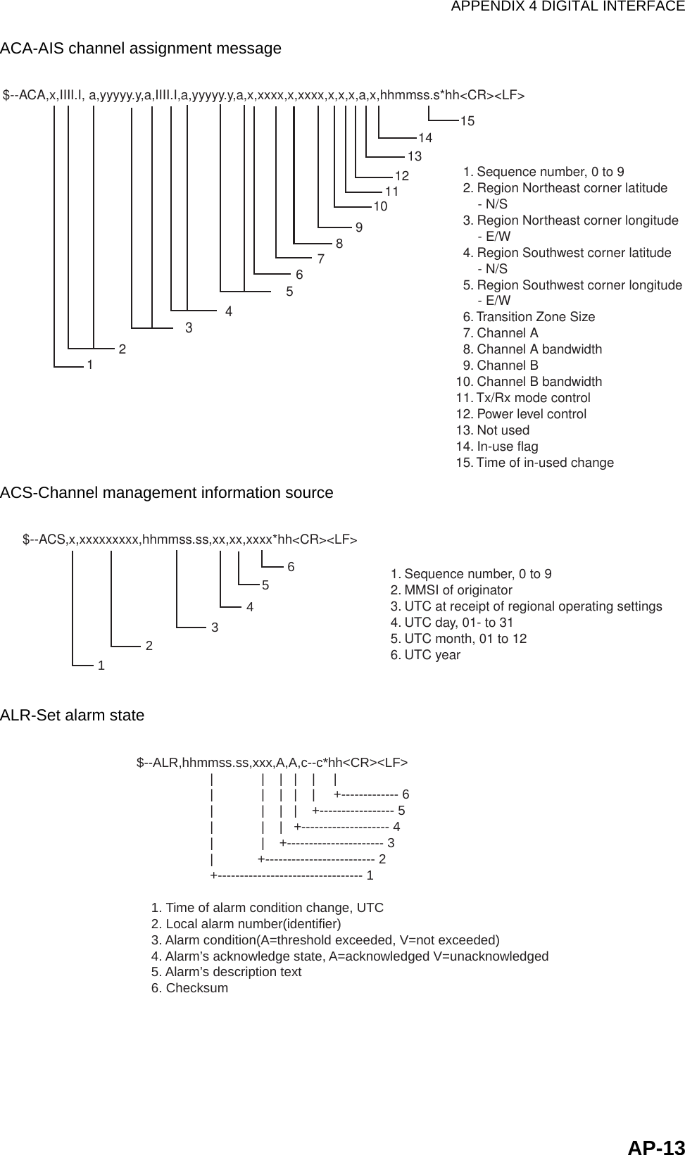
Operators Manual
2.
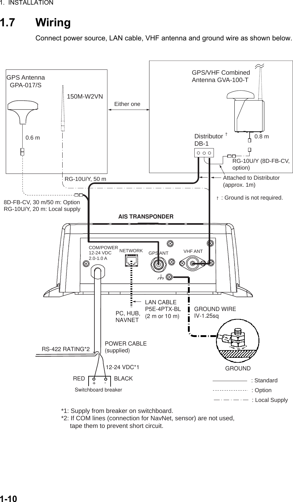
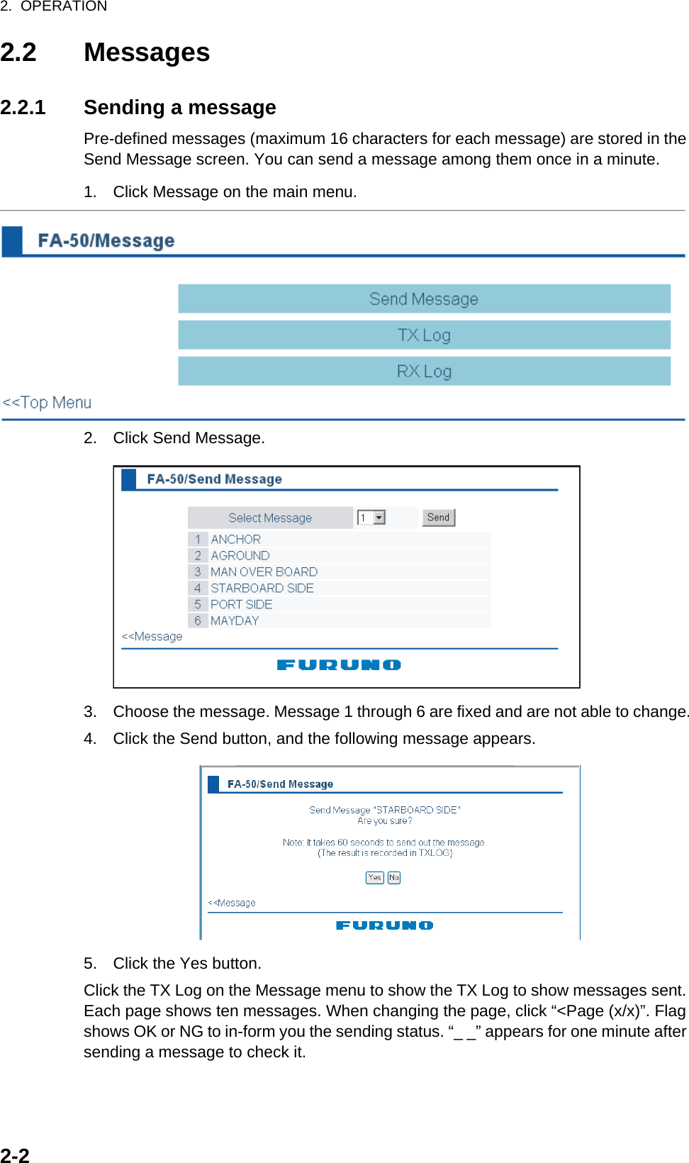
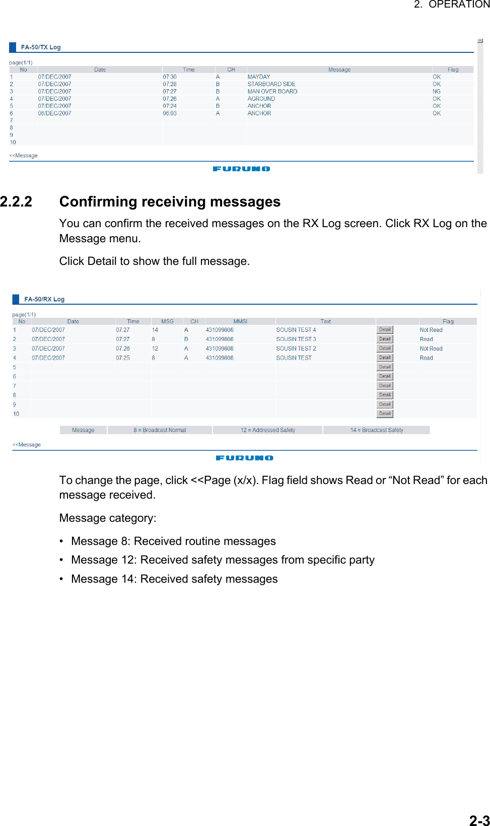
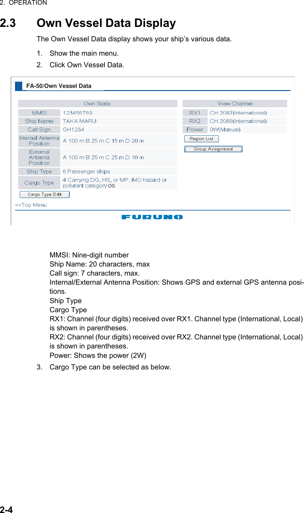
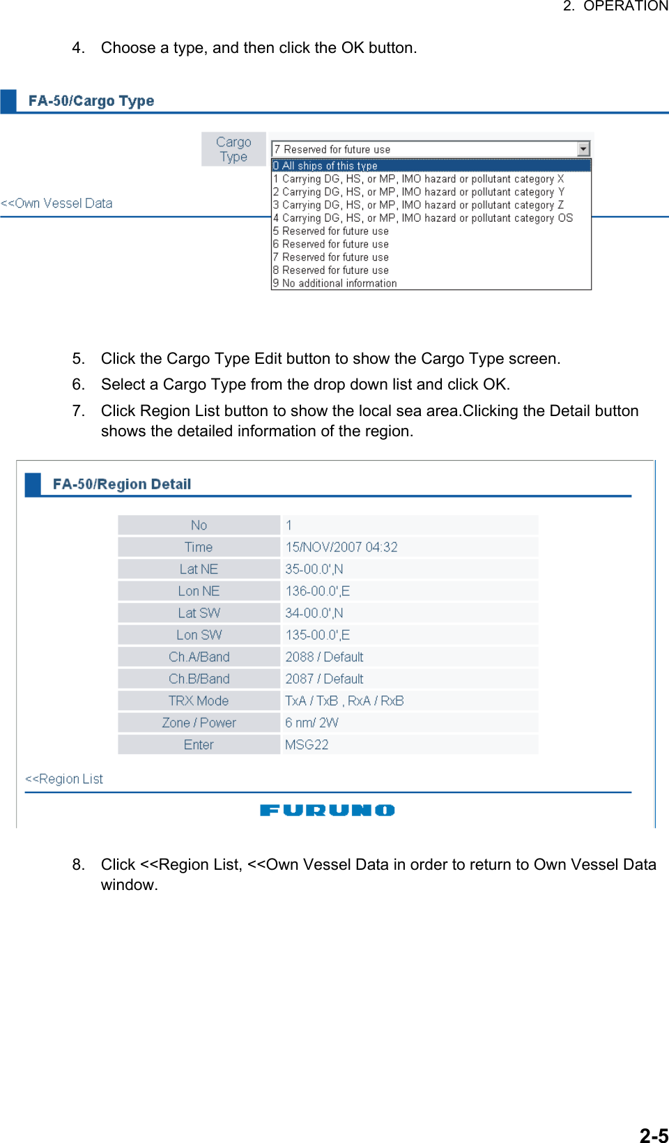
operation manual
operation manual
Navigation menu
Upload a User Manual
Namespaces
Wiki Guide
HTML
PDF
Info
Views
User Manual
Discussion / Help
Navigation
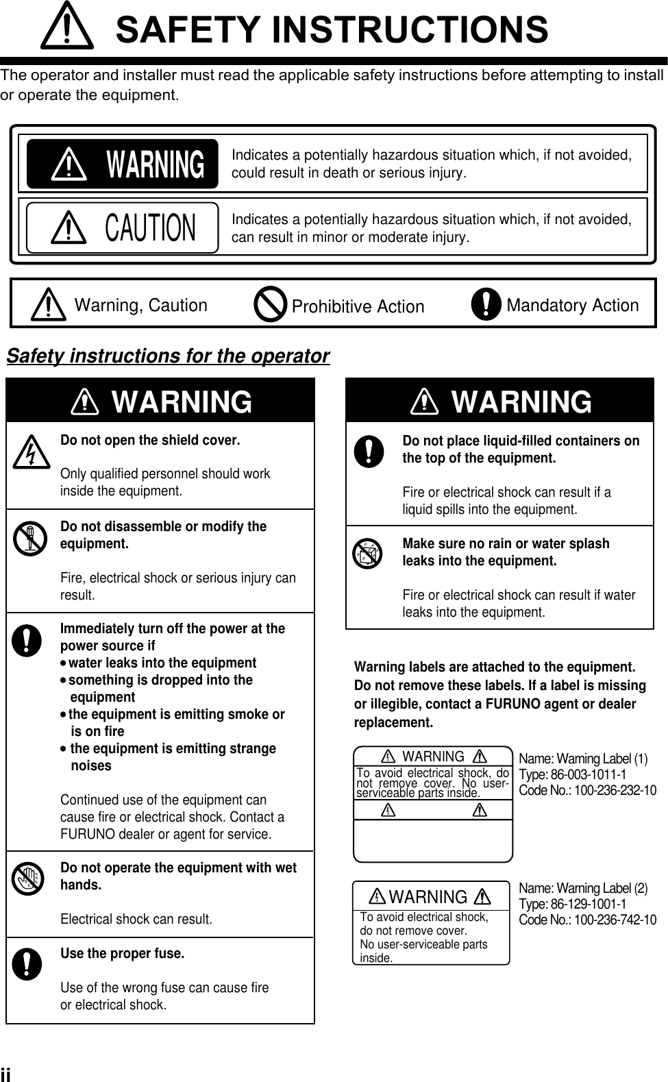
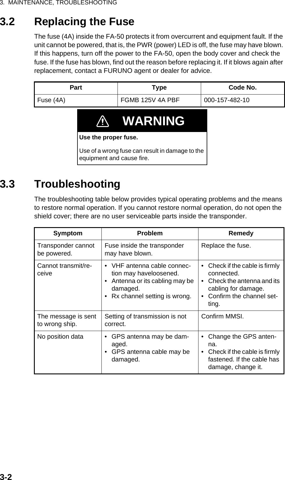
![PACKING LIST24AA-X-9853 -5 GVA-100,GVA-100-TN A M E O U T L I N E DESCRIPTION/CODE № Q'TY1/1ユニット UNIT複合空中線部GPS/VHF COMBINED ANTENNAGVA-100000-053-810-001**工事材料 INSTALLATION MATERIALS CP24-00141コネクタ(N)CONNECTORN-P-8DFB 座金000-140-463-002コンベックスPLASTIC BANDCV-200HT000-809-226-002CV-200HT000-162-191-10アンテナ取付金具ANTENNA FIXING BRACKET24-003-3015-0100-302-670-002ミガキ平座金FLAT WASHERM8 SUS304000-864-130-004六角ナット 1種HEX.NUTM8 SUS304000-863-110-0081.コ-ド番号末尾の[**]は、選択品の代表型式/コードを表します。CODE NUMBER ENDING WITH "**" INDICATES THE CODE NUMBER OF REPRESENTATIVE MATERIAL.(略図の寸法は、参考値です。 DIMENSIONS IN DRAWING FOR REFERENCE ONLY.)24AA-X-9853型式/コード番号が2段の場合、下段より上段に代わる過渡期品であり、どちらかが入っています。 なお、品質は変わりません。TWO TYPES AND CODES MAY BE LISTED FOR AN ITEM. THE LOWER PRODUCT MAY BE SHIPPED IN PLACE OF THE UPPER PRODUCT. QUALITY IS THE SAME.A-1](https://usermanual.wiki/Furuno-USA/9ZWFA50.operation-manual/User-Guide-1011855-Page-56.png)