Furuno USA 9ZWFA50 Automatic Identification System User Manual PL
Furuno USA Inc Automatic Identification System PL
Contents
- 1. Operators Manual
- 2. operation manual
Operators Manual

www.furuno.co.jp

i
IMPORTANT NOTICES
• The descriptions in this manual are intended for readers with a solid knowledge of English.
• No part of this manual may be copied or reproduced without written permission.
• If this manual is lost or worn, contact your dealer about replacement.
• The contents of this manual and equipment specifications are subject to change without notice.
• The example screens (or illustrations) shown in this manual may not match the screens you
see on your display. The screen you see depends on your system configuration and equipment
settings.
• Store this manual in a convenient place for future reference.
• FURUNO will assume no responsibility for the damage caused by improper use or modification
of the equipment (including software) by an unauthorized agent or a third party.
• When it is time to discard this product it must be done according to local regulations for dis-
posal of industrial waste. For disposal in the USA, refer to the Electronics Industries Alliance
(http://www.eiae.org/).
ii
WARNING
Indicates a potentially hazardous situation which, if not avoided,
could result in death or serious injury.
CAUTION
Indicates a potentially hazardous situation which, if not avoided,
can result in minor or moderate injury.
Warning, Caution Mandatory Action
Prohibitive Action
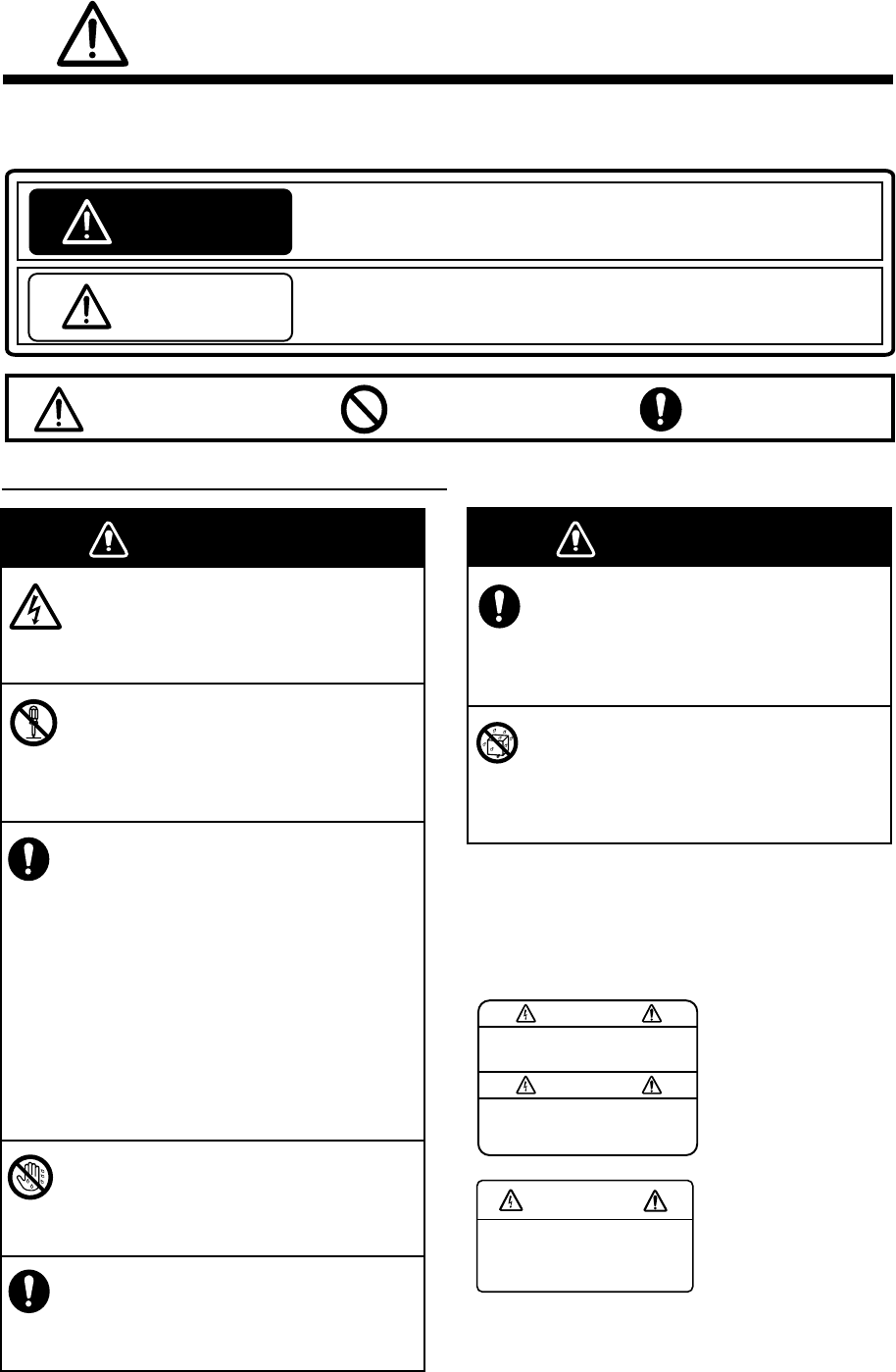
SAFETY INSTRUCTIONS
The operator and installer must read the applicable safety instructions before attempting to
install or operate the equipment.
WARNING
WARNING
Do not open the equipment.
Only qualified personnel should work
inside the equipment.
Do not disassemble or modify the
equipment.
Fire, electrical shock or serious injury can
result.
Immediately turn off the power at the
power source if
water leaks into the equipment
something is dropped into the
equipment
the equipment is emitting smoke or
is on fire
the equipment is emitting strange
noises
Continued use of the equipment can
cause fire or electrical shock. Contact a
FURUNO dealer or agent for service.
Do not operate the equipment with wet
hands.
Electrical shock can result.
Use the proper fuse.
Use of the wrong fuse can cause fire
or electrical shock.
WARNING
Do not place liquid-filled containers on
the top of the equipment.
Fire or electrical shock can result if a
liquid spills into the equipment.
Make sure no rain or water splash
leaks into the equipment.
Fire or electrical shock can result if water
leaks into the equipment.
.
WARNING
To avoid electrical shock, do
not remove cover. No user-
serviceable parts inside.
Name: Warning Label (1)
Type: 86-003-1011-1
Code No.: 100-236-231
WARNING
To avoid electrical shock,
do not remove cover.
No user-serviceable parts
inside.
Name: Warning Label (2)
Type: 86-129-1001-1
Code No.: 100-236-741
Warning labels are attached to the equipment.
Do not remove these labels. If a label is missing
or illegible, contact a FURUNO agent or dealer
about replacement.
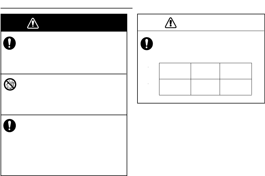
Safety instructions for the operator
iii
CAUTION
Observe the following compass safe
distances to prevent interference to a
magnetic compass:
Turn off the power at the switchboard
before beginning the installation.
Fire or electrical shock can result if the
power is left on.
Do not install the equipment where it
may get wet from rain or water splash.
Water in the equipment can result in fire,
electrical shock or damage to the equipment.
Be sure that the power supply is
compatible with the voltage rating of the
equipment.
Connecting an incompatible power supply
can cause fire or damage the equipment.
The voltage rating appears on the inlet
of power.
Standard
compass
Steering
compass
0.30 m 0.30 m
FA-50
WARNING
Safety instructions for the installer

iv
TABLE OF CONTENTS
FOREWORD .........................................................................................................v
SYSTEM CONFIGURATION...............................................................................vii
SYSTEM OVERVIEW.........................................................................................viii
1. INSTALLATION ................................................................................................1
1.1 Equipment Lists ..................................................................................................................1
1.2 AIS transponder FA-50 .......................................................................................................2
1.3 Whip Antenna ..................................................................................................................... 3
1.4 GPS Antenna...................................................................................................................... 4
1.5 GPS/VHF Combined Antenna ............................................................................................6
1.6 Power Supply (option) ........................................................................................................8
1.7 Wiring .................................................................................................................................9
1.8 Setting Adjustments..........................................................................................................11
2. OPERATION ...................................................................................................16
2.1 AIS Transponder FA-50....................................................................................................16
2.2 Messages ......................................................................................................................... 17
2.3 Own Vessel Data Display .................................................................................................18
2.4 Alarm Status .....................................................................................................................20
2.5 Sensor Status ...................................................................................................................21
3. MAINTENANCE, TROUBLESHOOTING........................................................22
3.1 Maintenance .....................................................................................................................22
3.2 Replacing the Fuse...........................................................................................................23
3.3 Troubleshooting................................................................................................................23
3.4 Diagnostics .......................................................................................................................24
APPENDIX ......................................................................................................AP-1
Menu Tree ..........................................................................................................................AP-1
VHF CHANNEL LIST..........................................................................................................AP-2
Parts List.............................................................................................................................AP-4
Parts Location.....................................................................................................................AP-5
Digital Interface...................................................................................................................AP-6
SPECIFICATIONS...........................................................................................SP-1
OUTLINE DRAWINGS ...................................................................................... D-1
INTERCONNECTION DIAGRAM...................................................................... S-1

v
FOREWORD
A Word to the Owner of the FA-50
Congratulations on your choice of the FURUNO FA-50 AIS Transponder. We are con-
fident you will see why the FURUNO name has become synonymous with quality and
reliability.
For over 50 years FURUNO Electric Company has enjoyed an enviable reputation for
quality marine electronics equipment. This dedication to excellence is furthered by our
extensive global network of agents and dealers.
This equipment is designed and constructed to meet the rigorous demands of the ma-
rine environment. However, no machine can perform its intended function unless op-
erated and maintained properly. Please carefully read and follow the recommended
procedures for operation and maintenance.
Thank you for considering and purchasing FURUNO equipment.
Features
The FA-50 is a Class B AIS (Automatic Identification System) capable of exchanging
navigation and ship data between own ship and other ships or coastal stations. It com-
plies with IMO MSC. 74(69) Annex 3, A.694, ITU-R M.1371-2 and DSC ITU-R M.825.3
It also complies with IEC 62287-1 (Type testing standard), IEC 60945 (EMC and en-
vironmental conditions).
FA-50 consists of VHF and GPS antennas, a transponder unit and several associated
units. The transponder contains a VHF transmitter, two TDMA receivers on two paral-
lel VHF channels, interface, communication processor, and internal GPS receiver.
The internal GPS is a 12-channel all-in-view receiver with a differential capability. It
also gives position, COG and SOG when the external GPS wails. FA-50 receives
DSC, time-sharing with TDMA receiver.
The main features are
• Safety of navigation by automatically exchanging navigational data
• Static data
-MMSI (Maritime Mobile Service Identity)
-Call sign & name
-Length and beam
-Type of ship
-Location of position-fixing antenna on the ship

vi
• Dynamic data:
-Ship’s position with accuracy indication and integrity status
-Universal Time Coordinated (UTC)
-Course over ground (COG)
-Speed over ground (SOG)
-Heading
• Voyage-related data
-Hazardous cargo (type)
• Short safety-related messages, pre-set messages
• Interfaces for radar, PC for future networking expansion
• GPS/VHF combined antenna for easy installation available
• Built-in GPS receiver for position-fixing device
Program Version
**: Minor change
Item Program No. Version No. Date
FA-50 AIS Transponder Main Program xxx xxx July 2007
vii
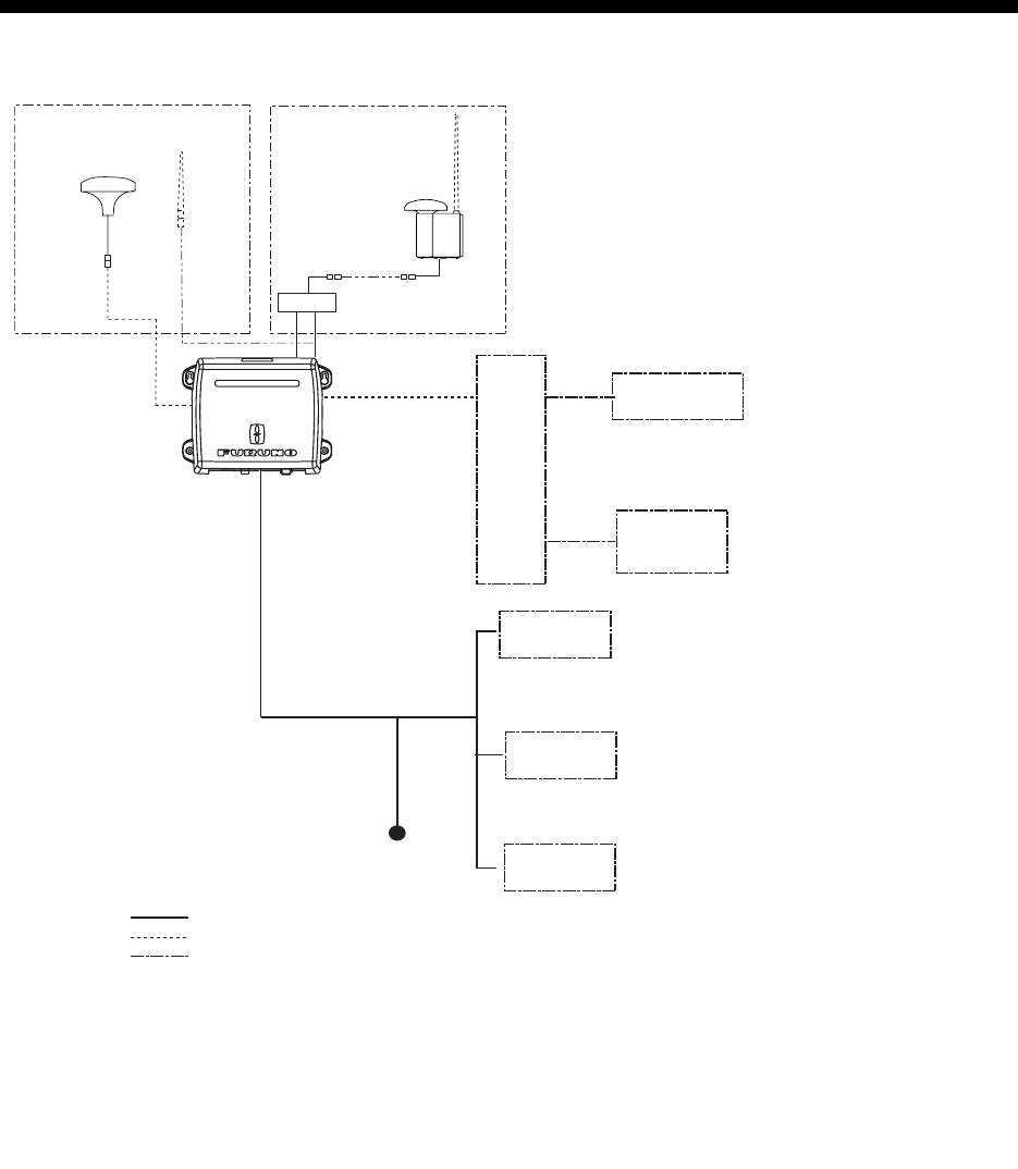
SYSTEM CONFIGURATION
AIS TRANSPONDER
FA-50
HUB
SENSOR
OR
12-24 VDC IF-1500AIS
OR
FR-8xx2 SERIES
GPS* (ex. GP-150)
SPEED LOG
GYROCOMPASS
SATELLITE COMPASS
NAVNET
RADAR
CHART PLOTTER
ECDIS
PILOT PLUG
PC
w/FAISPC MX
EXTERNAL
DISPLAY
: Standard supply
: Optional supply
: Local supply
NAVNET
EXTERNAL
DISPLAY
GPS/VHF
combined antenna
GVA-100
GPS antenna
GPA-017S or 017
Distributor unit
DB-1
VHF
antenna
Either
*Usaually FA-50 uses the internal GPS. When connecting the
external GPS, use one which satisfies the followings.
1) Outputs DTM sentence (WGS-84 can be chosen.)
2) Outputs GBS sentence.
3) Outputs sentences with the mode indicator;
4) The measured result of internal and external GPSs should be
within 26 m.(These antenna should be located within 6 m.)
We, FURUNO, prepare GPS navigator GP-150 as the equipment
meetin
g
with requirements shown above.
GNS: Ver.3.0 and later
GLL: Ver.2.0 and later
GGA: Ver.2.0 and later
RMC: Ver.1.5 and later
viii
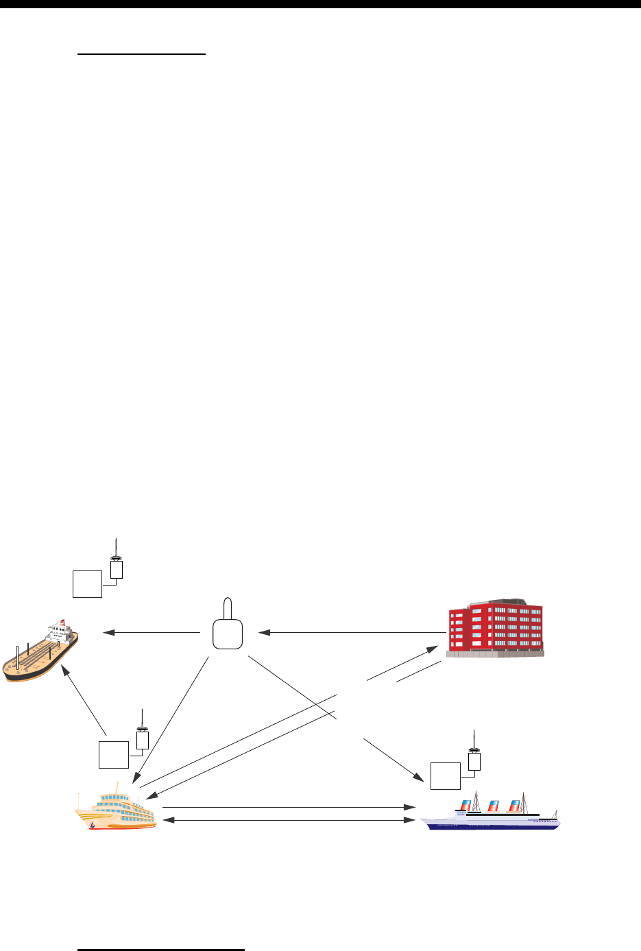
SYSTEM OVERVIEW
System overview
The Automatic Identification System (AIS) was originally developed to aid the Vessel
Traffic Services (VTS) by use of a VHF transponder working on DIgital Selective Call
(DSC) at VHF CH70, and is still in use along the UL coastal areas and others. Some
time later the IMO developed a Universal AIS using the new sophisticated technology
called Carrier-Sence Time Division Multiple Access (CSTDMA) based on a VHF Data
Link (VDL).
The system operates in three methods - autonomous (continuous operation in all ar-
eas), assigned (data transmission interval remotely controlled by authority in traffic
monitoring service) and polled (in response to interrorgation from a ship or authority).
It is synchronized with GPS time to avoid conflict among multiple users (IMO minimum
2000 reports per minute and IEC requires 4500 reports on two channels). The VHF
channels 87B and 88B are commonly used and in addition there are local AIS frequen-
cies. Shipborne AIS transponders exchange various data as specified by the IMO and
ITU on either frequency automatically set up by the frequency management telecom-
mand received by the DSC on ship. AIS has Class A and Class B; Class A is the stan-
dard for SOLAS ships, Class B is for non-SOLAS. There are two type of transmission
method, SOTD MA (Self Organising Time Division Multiple Access) and CSTD MA
(Carrier Sence Time Division Multiple Access). Class B is the inexpencive and simple
AIS for easy mounting on boats.
Not all ships carry AIS
VTS center
Aids to
Navigation
(AtoN)
Transponder
VTS Center transmits TDMA CH
management message including
code, type, position, etc. of buoys
every 3 min, and the AtoN broadcasts
these messages for ships.
All ships broadcast Static and Dynamic information (autonomous and
continuous mode). If OS wants to know information about ship 1, OS shall
send an interrogation in polling mode; then ship 1 will transmit her
response on the same VHF channel without operator intervention.
Interrogation and Response
Static and Dynamic information incl.
MMSI, Name, POSN, HDG, COG, SOG
Ship 1
Own ship
The VTS center transmits a command on
frequency assignment, slots, report rate,
VHF output power, channel spacing, etc.
(Assigned mode)
AIS-fitted AtoN broadcasts its
identification, type of operation,
location, displacement, etc. at
3 min intervals or at a reporting
rate designated by the
Administration authorities.
Transponder
Trans-
ponder

ix
The Officer of the Watch (OOW) should always be aware that other ships, and in par-
ticular leisure craft, fishing boats and warships, and some coastal shore stations (in-
cluding Vessel Traffic Service centers) might not be fitted with AIS.
The OOW should also be aware that AIS fitted on other ships as a mandatory carriage
requirement might be switched off by the master if its use might compromise the se-
curity of the vessel. Thus, users are therefore cautioned to always bear in mind that
information provided by AIS may not be giving a complete or correct “picture” of ship-
ping traffic in their vicinity.
Use of AIS in collision avoidance
As an anti-collision aid the AIS has the following advantages over radar:
• Information provided in near real-time
• Capable of instant presentation of target course alterations
• Not subject to target swap
• Not subject to target loss in clutter
• Not subject to target loss due to fast maneuvers
• Able to detect ships within VHF/FM coverage, including in some circumstances,
around bends and behind islands.
When using the AIS for anti-collision purposes it is important to remember that the AIS
is an additional source of navigation information. It does not replace other navigational
systems. The AIS may not be giving a complete or correct “picture” of shipping traffic
in its vicinity.
The use of the AIS does not negate the responsibility of the OOW to comply with all
collision regulation requirements, especially the maintaining of a proper look-out. The
prudent navigator uses all aids available to navigate the ship.
Erroneous information
Erroneous information implies a risk to other ships as well as your own. Poorly config-
ured or improperly calibrated sensors might lead to incorrect information being trans-
mitted. It is the user’s responsibility to ensure that all information entered into the
system is correct and up to date.
1
1. INSTALLATION
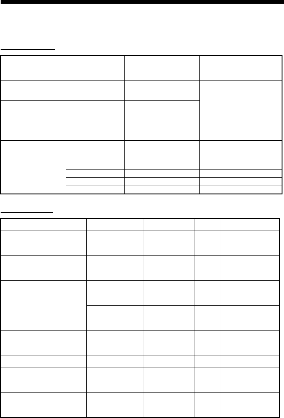
1.1 Equipment Lists
Standard supply
Optional supply
Name Type Code No. Qty Remarks
AIS Transponder FA-50-E - 1
GPS/VHF combined
antenna GVA-100 - 1 Select one.
GPS Antenna
(Select one) GPA-017S - 1 set
GPA017 - 1 set
Spare parts 1 set Fuse, FGB0-A 4A AC125V
Accessories 1 set FAISPC-MX (CD)
Installation Materials CP24-00141 005-952-330 1 set For transponder
CP24-00502 005-955-560 1 set For GPA-017S
- - 1 set For GPA-017
CP24-00141 005-952-330 1 set For GVA-100
CP24-00101 005-950-730 1 set For DB-1
Name Type Code No. Qty Remarks
AC-DC power supply PR-240-CE - 1
Whip antenna 150M-W2VN 000-113-498 1 For outside Japan
FAB-151D 000-572-029 1 For Japan only
Antenna fixing bracket 4-310071 000-572-184 1 For FAB-151D
Antenna cable set CP20-02700 004-381-160 1 For GPA-017S
CP20-02710 004-381-170 1 For GPA-017S
CP24-00300 000-041-938 1 For GVA-100
CP24-00310 000-041-939 1 For GVA-100
Coaxial cable TNC-PS-3D-15 000-133-670 1 TNC-TNC, 15 m
Right-angle antenna base No.13-QA330 000-803-239 1 For GPA-017/S
L-angle antenna base No.13-QA310 000-803-240 1 For GPA-017/S
Antenna base for rail mount No.13-RC5160 000-806-114 1 For GPA-017/S
Mast mount fixture CP20-01111 004-365-780 1 For GPA-017/S
AIS viewer FAISPC-MX 1
LAN cable P5E-4PTX-BL 1 2 m/10 m
2
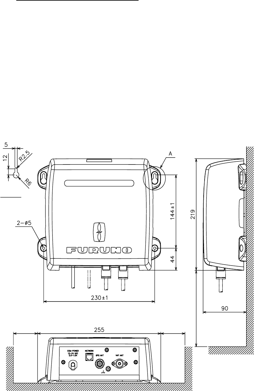
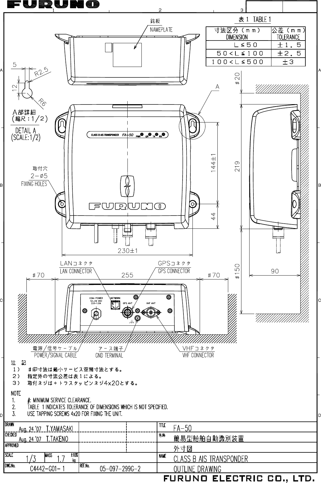
1.2 AIS Transponder FA-50
Mounting considerations, mounting
The FA-50 can be mounted on a desktop, deck or on a bulkhead. When selecting a
mounting location, keep the following points in mind:
• The temperature and humidity should be moderate and stable.
• Locate the unit away from exhaust pipes and vents.
• The mounting location should be well ventilated.
• Mount the unit where shock and vibration are minimal.
• Keep the unit away from electromagnetic field-generating equipment such as
motors and generators.
• A magnetic compass will be affected if the FA-50 is placed too close to it. Observe
the compass safe distances noted in the safety instructions to prevent disturbance
to the magnetic compass.
• Fix the unit to the mounting location with 4x20 self-tapping screws (supplied).
MORE THAN
70
"A" DETAIL
MORE THAN
70
All dimensions
in millimeters.
MORE THAN 150
3
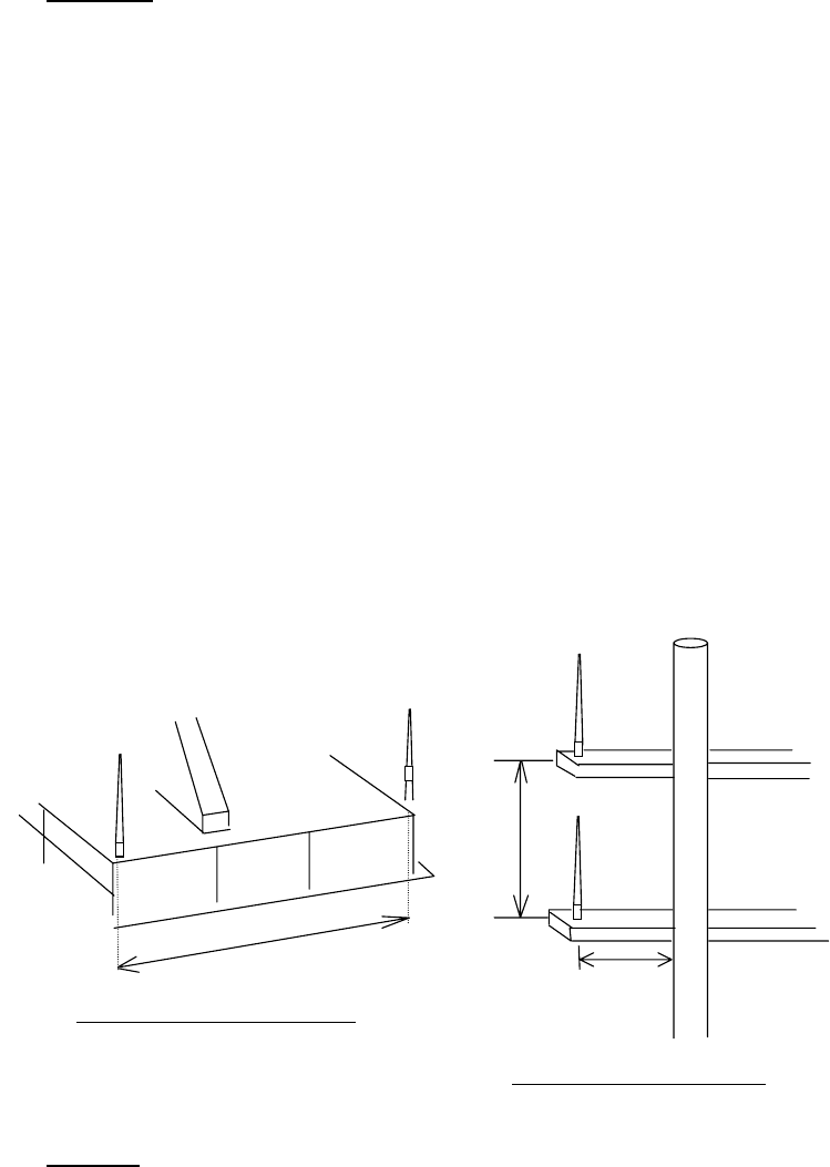
1.3 Whip Antenna
Location
The location of the AIS VHF-antenna should be carefully considered. Digital commu-
nication is more sensitive than analog/voice communication to interference created by
reflections in obstructions like masts and booms. It may be necessary to relocate the
VHF radiotelephone antenna to minimize interference effects. To minimize interfer-
ence effects, the following guidelines apply:
• The AIS VHF antenna should be placed in an elevated position that is as free as
possible with a minimum of 0.5 meters in the horizontal direction from constructions
made of conductive materials. The antenna should not be installed close to any
large vertical obstruction. The objective for the AIS VHF antenna is to see the hori-
zon freely through 360 degrees.
• There should not be more than one antenna on the same plane. The AIS VHF
antenna should be mounted directly above or below the ship’s primary VHF radio-
telephone antenna, with no horizontal separation and with a minimum of 2.8 meters
vertical separation. If it is located on the same plane as other antennas, the dis-
tance apart should be at least 10 meters.
• Install the VHF whip antenna (option) referring to the outline drawing at the back of
this manual. Separate this antenna from other VHF radiotelephone antennas as
shown below to prevent interference to the FA-50.
Cabling
• Use coaxial cable type 5D-2V or the equivalent.
• The cable should be kept as short as possible to minimize signal attenuation, and
the maximum length is 50 meters.
• All outdoor-installed connectors on coaxial cables should be fitted with preventive
isolation such as vulcanizing tape to protect against water penetration into the
antenna cable.
• Coaxial cables should be installed in separate signal cable channels/tubes and at
least 10 cm away from power supply cables. Crossing of cables should be done at
right angles (90 degrees). The minimum bend radius of the coaxial cable should be
5 times the cable's outer diameter.
Horizontal separation distance
More than 10 m
Vertical separation distance
Other VHF
whip antenna
More than 0.5 m
More than
2.8 m
Whip antenna
for AIS
4
1.4 GPS Antenna
Install the GPS antenna unit referring to the drawing on page D-5 or D-6 at the back
of this manual. When selecting a mounting location for the antenna, keep in mind the
following points.
• Select a location out of the radar beam. The radar beam will obstruct or prevent
reception of the GPS satellite signal.
• There should be no interfering object within the line-of-sight to the satellites.
Objects within line-of-sight to a satellite, for example, a mast, may block recep-
tion or prolong acquisition time.
• Mount the antenna unit as high as possible to keep it free of interfering objects
and water spray, which can interrupt reception of GPS satellite signal if the water
freezes.
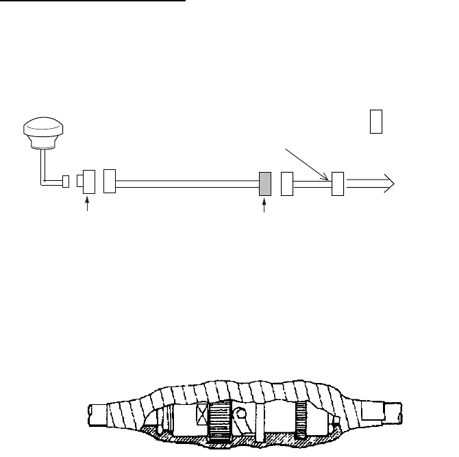
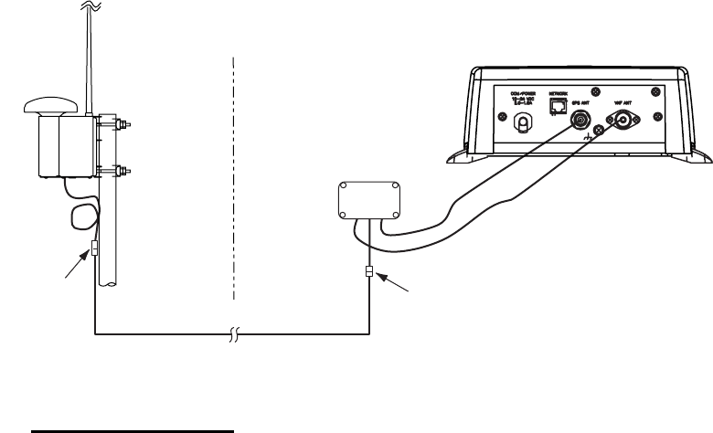
Extending antenna cable
Three types of antenna cable extensions are optionally available.
a) Antenna cable set CP20-02700
• Waterproofing connector
Wrap connector with vulcanizing tape and then vinyl tape. Bind the tape end with a
cable-tie.
Waterproofing connector
b) Antenna cable set CP20-02710 (8D-FB-CV, 50m)
Connect the cable the same as a) above.
c) Cable type RG-10/UY (shipyard supply)
Note: The length of this cable should be less than 20 m to prevent signal loss. The
coax. coupling cable assy.(type: NJ-TP+3DXV-1, code no. 000-123-809), coaxial con-
nector(N-P-8DFB; supplied), vulcanizing tape and vinyl tape are required. Fabricate
both ends of the cable as shown in the figure on the next page.
Antenna Unit
Antenna Cable
30m 1 m
Fabricate locally. (See next page.)
N-P-8DFB
FA-50
: Connector
Conversion
Cable Assy.
NJ-JP-3DXV-1
TNCP-NJ
0.6m
5
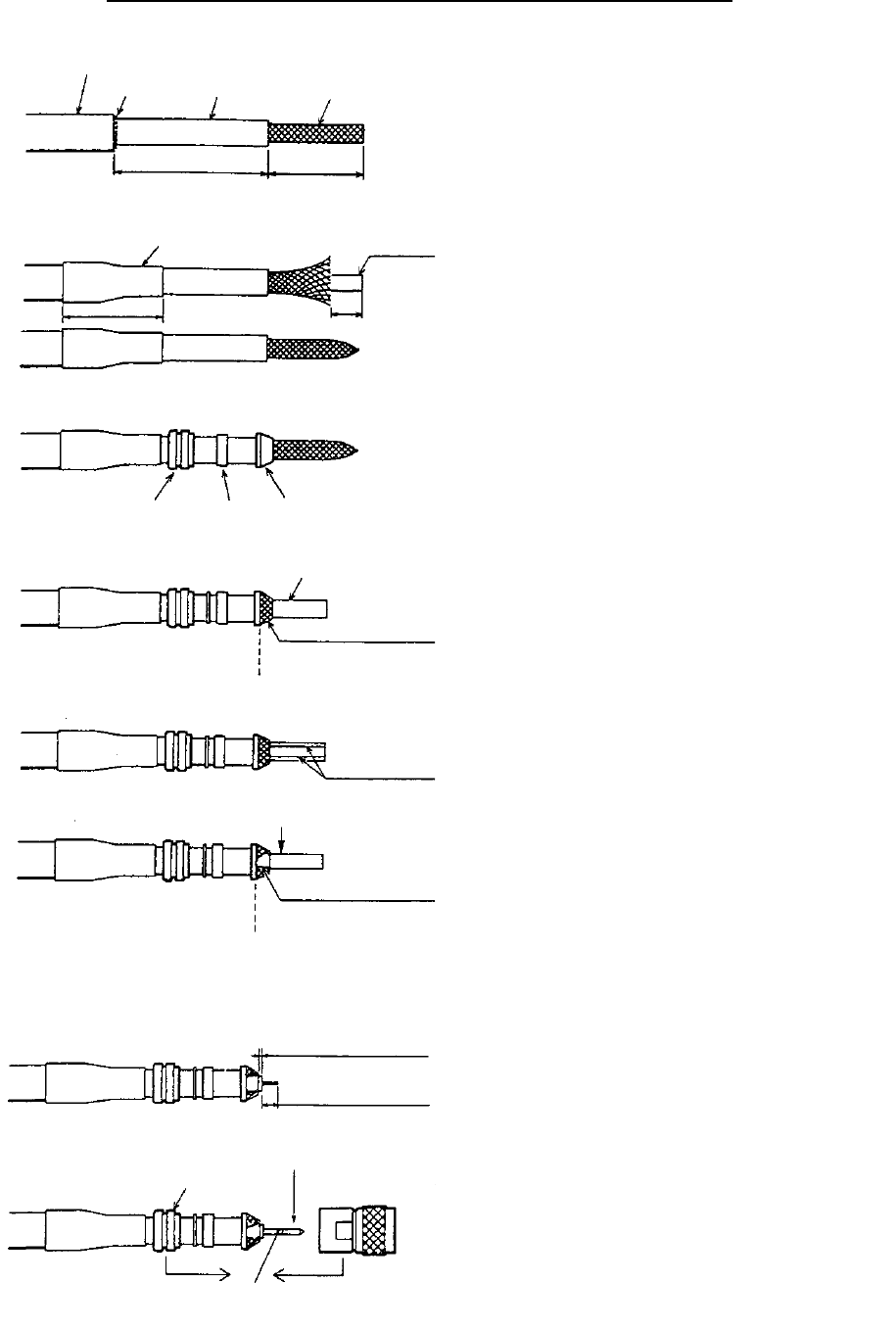
How to attach the connector N-P-8DFB for cable 8D-FB-CV
How to attach connector N-P-8DFB
Outer Sheath
Armor
Dimensions in millimeters.
Inner Sheath Shield
Remove outer sheath and armor by the dimensions
shown left.
Expose inner sheath and shield by the dimensions
shown left.
Cut off insulator and core by 10mm.
Twist shield end.
Slip on clamp nut, gasket and clamp as shown left.
Fold back shield over clamp and trim.
Cut aluminum foil at four places, 90° from one
another.
Fold back aluminum foil onto shield and trim.
Expose the insulator by 1mm.
Expose the core by 5mm.
Slip the pin onto the conductor. Solder them togethe
r
through the hole on the pin.
Insert the pin into the shell. Screw the clamp nut into
the shell.
(Tighten by turning the clamp nut. Do not tighten by
turning the shell.)
Cover with heat-shrink tubing and heat.
30 10
Clamp
Nut Gasket
(reddish
brown)
Clamp
Aluminum Foil
Trim shield here.
Trim aluminum
tape foil here.
Insulator
1
5
Clamp Nut Pin
Shell
Solder through
the hole.
50 30
6
1.5 GPS/VHF Combined Antenna
Install the combined antenna unit referring to the outline drawing. When selecting a
mounting location for the antenna, keep in mind the following points.
• Select a location out of the radar beam. The radar beam will obstruct or prevent
reception of the GPS satellite signal.
• There should be no interfering object within the line-of-sight to the satellites.
Objects within line-of-sight to a satellite, for example, a mast, may block recep-
tion or prolong acquisition time.
• Mount the antenna unit as high as possible. Mounting it this way keeps it free of
interfering objects and water spray, which can interrupt reception of GPS satel-
lite signal if the water freezes.
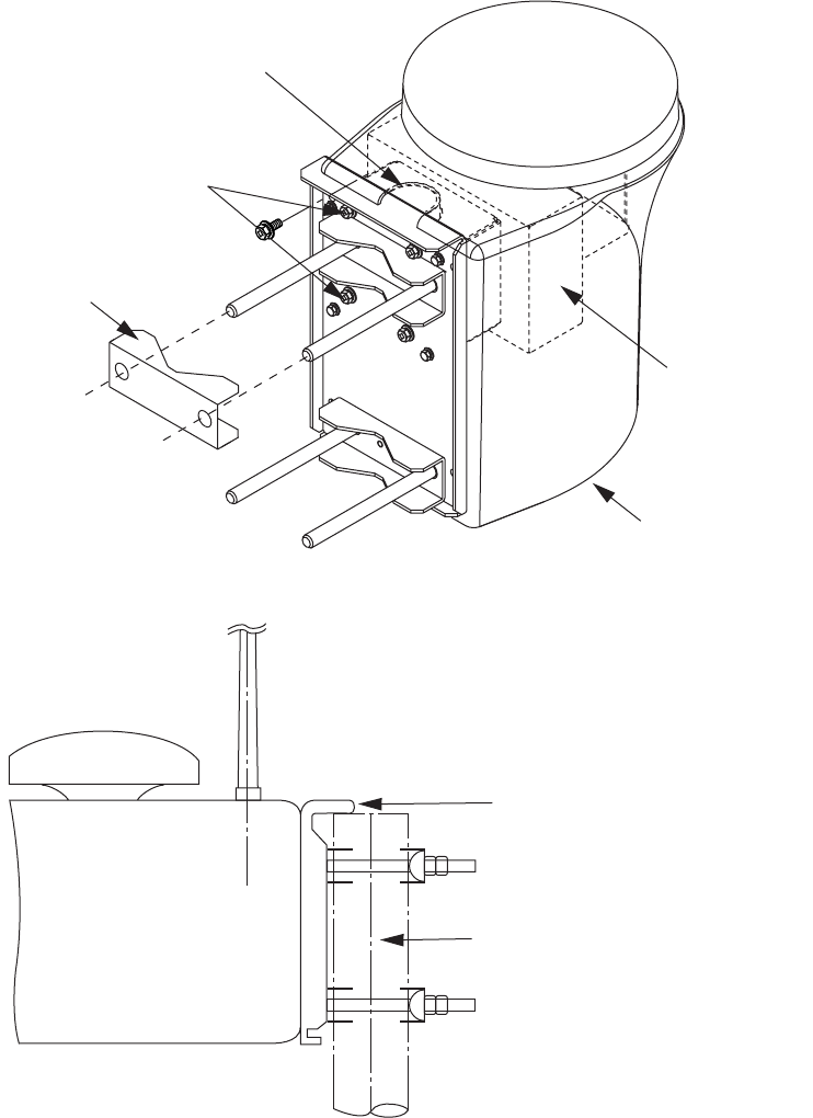
Installation overview of GPS/VHF combined antenna
Mounting procedure
1. Dismount the bottom cover, cut the cable-tie inside the unit and take out the coax-
ial connector attached to the combined box.
2. Loosen four screws to loosen whip antenna fixture and pull out the coaxial con-
nector coming from the combined box through the hole in the whip antenna fixture.
3. Connect the coaxial connector to the whip antenna base and wrap the junction
part of the whip antenna with vulcanizing tape and then vinyl tape for waterproof-
ing.
4. Insert the whip antenna from the top of the combined antenna.
5. Secure the whip antenna with whip antenna fixture.
6. Using a new plastic band (supplied), secure the cables and coaxial connector
inside the antenna case.
7. Mount the bottom cover.
8. Fix the GPS/VHF combined antenna to the ship’s stanchion (40 to 50 mm diame-
ter) with antenna fixing brackets, flat washers and hex. nuts.
Note: Coat the exposed parts of bolts and nuts with silicon sealant.
Outdoor Indoor
N-P-8DFB
N-P-8DFB
Distributor DB-1
GPS
AIS Transponder
FA-50
VHF
RG-10U/Y
7
GPS/VHF Combined antenna
A
ntenna fixing bracket
Loosen four screws.
(M5x16)
Bottom cover
Combined box
Whip antenna fixture
Stanchion
The top of the stanchion comes
into contact with the flange.
8
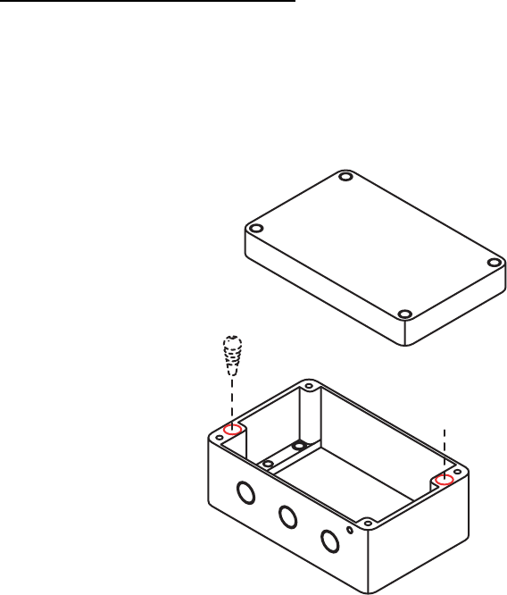
Installing distributor unit DB-1
The length of the cable between the distributor unit and transponder unit is 1 m so lo-
cate the distributor unit within 1 m from the transponder unit. Fix the distributor unit on
the bulkhead, facing the cable entrance downward. Remove the lid of the distributor
unit and secure the unit with two self-tapping screws.
Note: Be sure no foreign material or water enters the distributor unit.
1.6 Power Supply (option)
When selecting a mounting location for the unit, keep the following in mind:
• Keep the unit out away from areas subject to water splash.
• Locate the unit away from exhaust pipes and vents.
• The mounting location should be well ventilated.
• Mount the unit where shock and vibration are minimal.
• A magnetic compass will be affected if the unit is placed too close to it. Observe
the following compass safe distances to prevent disturbance to the magnetic
compass:
-Steering compass: 0.6 m
-Standard compass: 0.9 m
Fix the unit with four self-tapping screws (4x16) to a desktop or the deck as shown in
the figure below. It is not necessary to open the cover.
Self-tapping screw
(4x30)
9
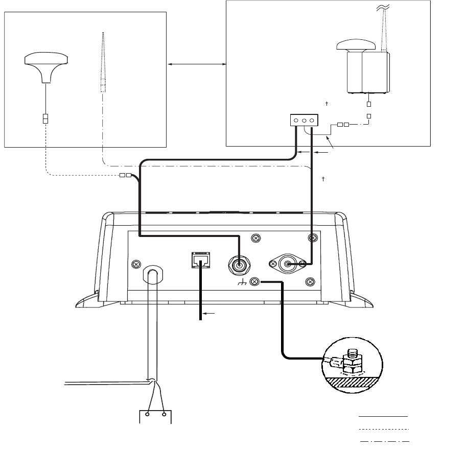
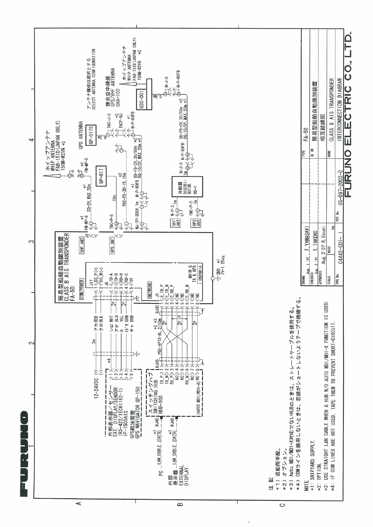
1.7 Wiring
Connect power source, LAN cable, VHF antenna and ground wire as shown
below.
RED BLACK
PC, HUB,
NAVNET
GROUND
GROUND WIRE
IV-1.25sq
LAN CABLE
P5E-4PTX-BL
(2 m or 10 m)
AIS TRANSPONDER
POWER CABLE
(supplied)
12-24 VDC
RS-422 RATING
Switchboard breaker
+-: Standard
: Option
: Local Supply
GPS Antenna
GPA-017/S
150M-W2VN
or FAB-151D
Either one
RG-10U/Y
RG-10U/Y (8D-FB-CV
for more than 20 m)
Attached to Distributor
(approx. 1m)
Distributor unit
DB-1
GPS/VHF Conbined
Antenna GVA-100
8D-FB-CV, 30 m/50 m: Option
RG-10U/Y: Local supply
0.6 m
*
*
*
0.8 m
: Ground is not required.
Note 1: Supply from breaker on switchboard.
Note 2: If COM lines (connection for NavNet, sensor) are not used, tape tham to prevent short circuit.
10
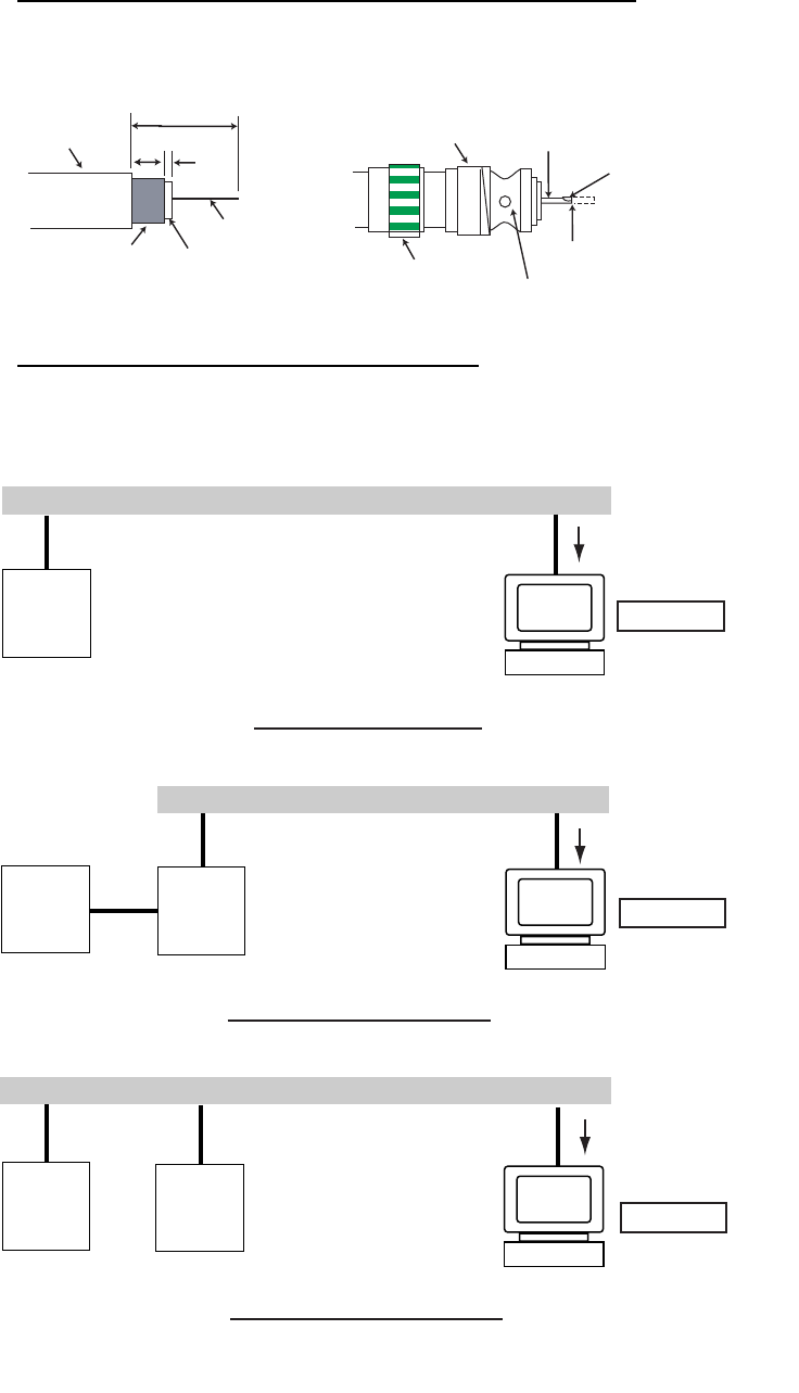
Attaching coaxial connector (M-P-5) to coaxial cable
The antenna cable (coaxial cable, type 5D-2V) is terminated at the FA-50 with an
M-P-5 coaxial connector. Attach the connector to the cable as shown below.
Connection of AIS viewer (FAISPC-MX)
The AIS viewer may be connected to the FA-50 directly, or to both FA-50 and NavNet
vx2. See the figure below for connection examples.
Sheath 30 mm
7 mm 2
mm
Conductor
Insulator
Braided
shield
Fasten tightly. Contact sleeve
Cut conductor here.
Coupling
ring
Solder here.
Solder here.
DIRECT CONNECTION
PC FAISPC-MX
FA-50 NavNet
VX2*
LAN
Data sentences
VDM, VDO, L/L,
SOG, COG, HDT
NavNet VX2 CONNECTION
PC FAISPC-MX
FA-50 NavNet
VX2
LAN Data sentences
VDM, VDO,
L/L, SOG, COG, HDT
NavNet vx2 CONNECTION
PC FAISPC-MX
FA-50
LAN
Data sentences
VDM, VDO
*Required updating software.
11
1.8 Setting and Adjustments
After installing the equipment, set up the COM port, Network and own ship’s static in-
formation (MMSI, ship’s name, call sign, antenna position and type of ship). The FA-
50 is set up from the PC or external display. The procedure below shows how to set
up any setting from a PC.
1.8.1 COM Port Setup, Network Setup
NOTICE: Only one FA-50 may be connected to the network.
Start up
1. Start up the PC and enter IP address and subnet mask.
1) Right-click My Network and Properties.
2) Right-click Local Area Network and Properties.
3) Select Internet Protocol and Properties.
4) Enter IP address 172.31.24.xxx (xxx=any three digits from 1 to 254, except 3).
5) Enter subnet mask 255.255.0.0.
2. Open Internet Explorer and do the following:
1) Click Tools on the menu bar.
2) Click Internet Options.
3) The General tab is selected. Click Settings at Temporary Internet Files.
4) Click the radio button “Every visit to the page” at “Check for newer versions of
stored page”.
5) Click the OK button.
6) Click the OK button again.
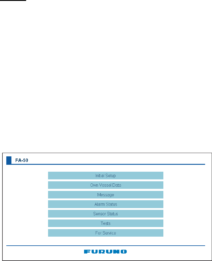
3. Enter URL as http://172.31.24.3 and press the Enter key.
12
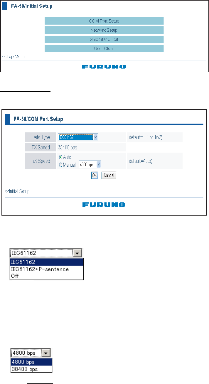
4. Click Initial Setup to show the Initial Setup screen.
COM port setup
5. Click COM PORT Setup to show the COM Port Setup screen.
6. The default setting for Data Type is IEC61162, which is suitable for most installa-
tions. If change is necessary, click the Data Type drop-down list and choose data
type as applicable, among the following choices.
IEC61162: Transmit and receive IEC61162 format data via COM port. (P sen-
tences are received but not transmitted.)
IEC61162+ P-sentence: Transmit and receive IEC61162+P sentences format
data via COM port.
Off: FA-50 transmits no data.
With the radio buttons at RX Speed, choose how RX speed is regulated, Auto or
Manual. For manual, choose speed from the drop-down list.
Note: Tx speed is fixed at 38400 bps.
7. Click OK to confirm setting.
8. Click "<<Port Setup" to return to the Port Setup menu.
(default=IEC61162)
13
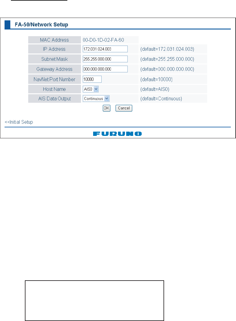
NETWORK setup
9. Click Network Setup to show the Network Setup screen.
10.Enter the IP address assigned to the FA-50.
11.Enter subnet mask for the network.
12.Enter gateway address.
13.For NavNet connection, enter NavNet port number at NavNet Port Number. Enter
ten-thousandths and one-thousandths places
14.At Host Name, enter host name to be used in NavNet, AIS0 - AIS9.
15. At AIS Data Output, select how to output AIS data.
Auto: Auto-detect of where to output AIS data.
Continuous: Output data continuously. Select if interfaced with FAISPC_MX.
Note: It is not necessary to change the settings of NavNet Port Number, Host
Name and AIS Data Output. Connection is available without adjusting them.
16.Click the OK button to finish.
17.If you changed a setting, the message below appears.
18.Click the Yes button to restart. "ER" LED on the FA-50 lights. After the LED goes
off access is given.
19.The message “Please close the window.” appears. Close the browser.
After restart is completed, it is necessary to access the FA-50 using new values. For
example, if you changed the IP address, use the new address to access the FA-50.
You must restart your FA-50
before the new settings take effect.
Do you want to restart your FA-50 now?
(It will take about 1 minute to restart your FA-50).
14
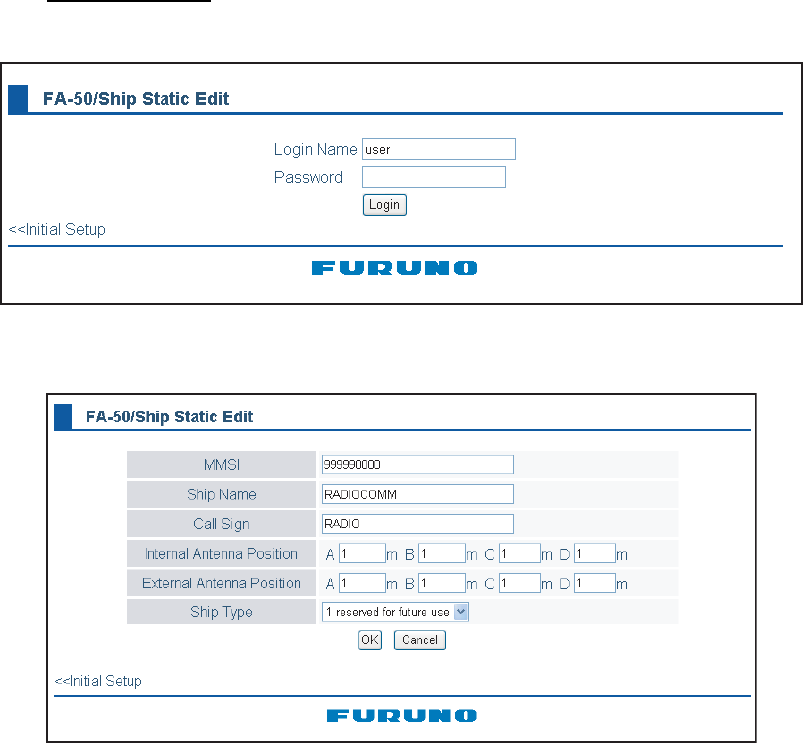
Ship static edit
20.Click Ship Static Edit to show the Network Setup menu.
21.Enter the password. The Ships Static Edit screen appears. Note that the pass-
word is known by only the FURUNO dealer.
22.Enter ship’s MMSI (Maritime Mobile Service Identity) in nine digits.
23.Enter ship’s name, using up to 20 alphanumeric characters.
24.Enter call sign, using seven alphanumeric characters.
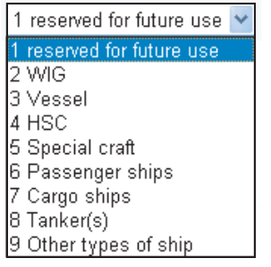
25.Set Internal/External antenna positions as follows:
1) Enter distance for for location “A” of FA-50 GPS antenna.
A: Distance from bow to GPS antenna position, setting range: 0-511 m
2) Enter distance for location B, C and D similar to how you did for “A” above.
B: Distance from stern to GPS antenna position, setting range: 0-511 m
C: Distance from port to GPS antenna position, setting range: 0-63 m
D: Distance from starboard to GPS antenna position, setting range: 0-63 m
3) Enter distance for location of an external GPS antenna (if connected) similar to
how you did for the internal GPS antenna.
15
26.Click the down-allow button for Ship Type to show the option window, and then
choose a ship type. (WOIG: Wing in ground, HSC: High speed craft)
27.After finishing all settings, Click the OK button.
16
2. OPERATION
2.1 AIS Transponder FA-50
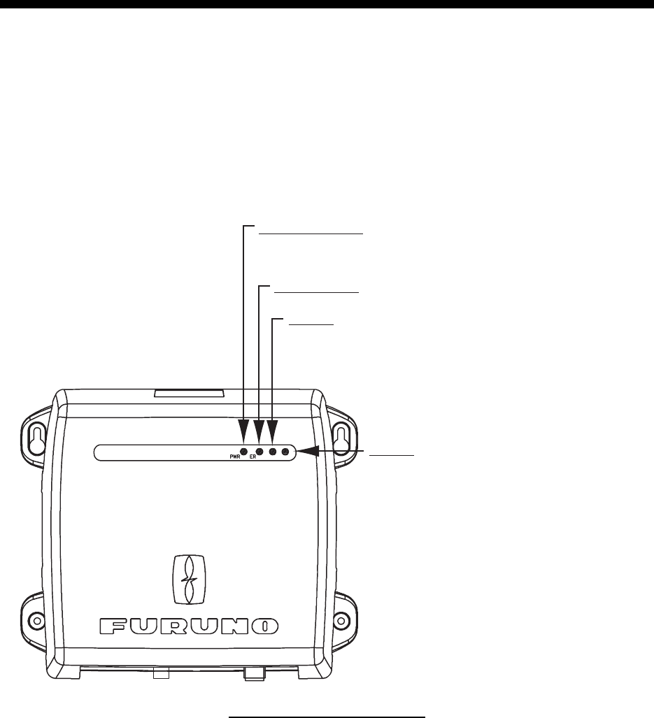
The FA-50 has no power switch. Power is fed from the ship’s switchboard, and a pow-
er switch on the switchboard turns the FA-50 on or off. When powered, the PWR LED
(green) on the cover lights. The three other LEDs on the cover flash or light with equip-
ment state. The ER LED (red) lights while the equipment is being initialized, and flash-
es when equipment error is found. The RX LED (orange) lights when receiving.The TX
LED lights blue when transmitting, orange when TX time out is occurs.
Sending/receiving Messages
You may send and receive messages via the VHF link, to a specified destination (MM-
SI) or all ships in the area. Messages can be sent to wan of safety of navigation; for
example, an iceberg sighted. Routine messages are also permitted.
Short safety-related messages are only an additional means to broadcast safety infor-
mation. they do not remove the requirements of the GMDSS.
The contents of the message may be viewed on the receive message log.
RX LED
Lights (in orange) 50 ms when channel
RX1/RX2 is receiving.
ER (Error) LED
Flashes (in red) for RAM, ROM, RX1+RX2 error.
PWR (Power) LED
Lights (in green) when power is on.
TX
TX LED
-Lights (in blue) when channel TX1/TX2 is
transmitting.
-Lights (in orange) when TX1/TX2 cannot be
transmitted continuously (Tx time out*.)
RX
*Lights also when not registering MMSI.
17
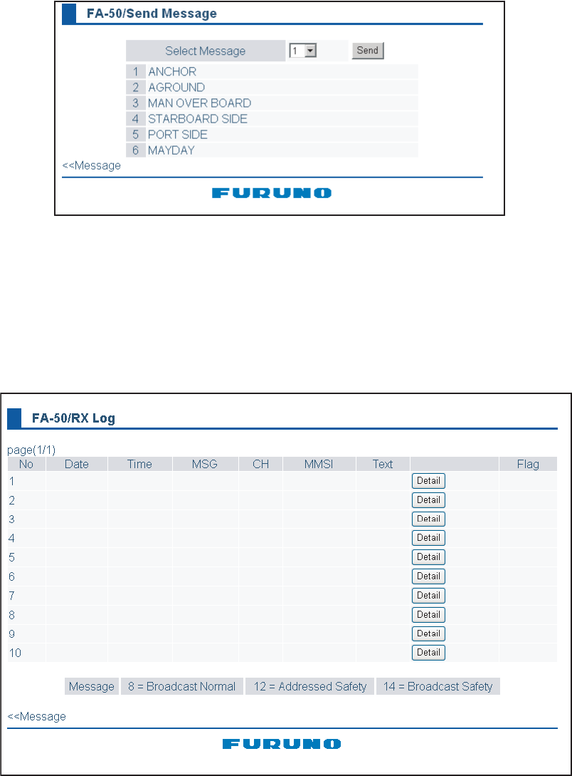
2.2 Messages
2.2.1 Sending a message
14 pre-difined messages (maximum 16 characters for each message) are stored in the Send Mes-
sage screen. You can send a message among from these once in a minute.
1. Click Message on the main menu.
2. Click the Send Message.
3. Choose the message to be sent, among from No.1 to 10 pre-set.
4. Click the Send button.
2.2.2 Confirming receiving messages
You can confirm the received messsages on the RX Log screen. Click “RX Log” on
the main menu.
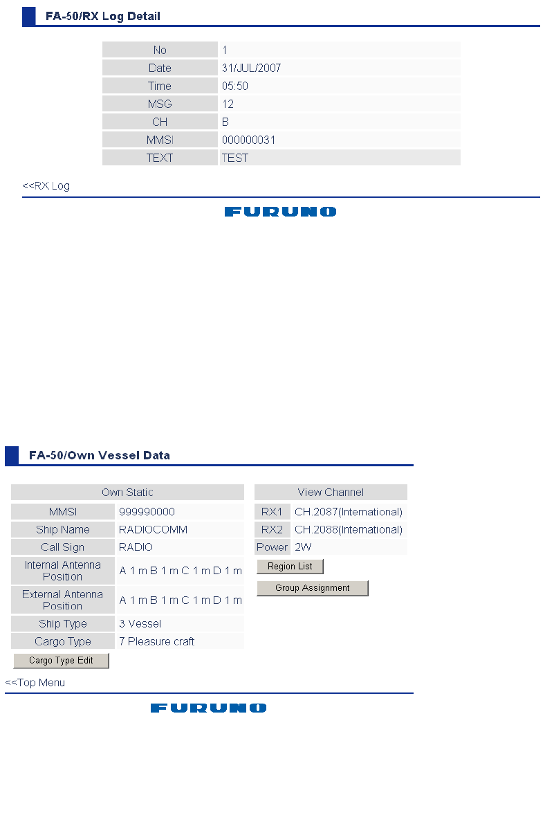
18
For detailed information about a messgae, click appropriate “Detail” to show the RX
Log Detail screen.
2.3 Own Vessel Data Display
The Own Vessel Data display shows your ship’s MMSI No., RX channel Nos., and
channel selection method.
1. Show the main menu.
2. Click Own Vessel Data.
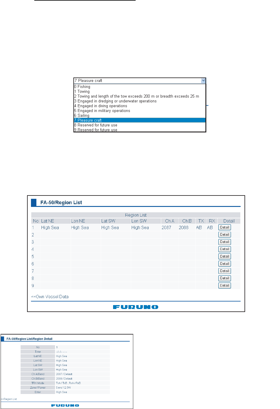
19
Description of own vessel data
MMSI: MMSI number (nine-digit number).
Ship Name: Ship’s name (20 characters)
Call Sign: Call signe (7 characters)
Internal/External Antenna Position: Shows antenna posiiton.
Ship Type: The ship type is shown by a digit number.
Cargo Type: Choose the cargo type as below.
1) Click the Cargo Type Edit button to show the Cargo Type screen.
2) Choose a type, and then click the OK button.
RX1: Channel (four digits) received over RX1. Channel type (International, Local) is
shown in parentheses.
RX2: Channel (four digits) received over RX2. Channel type (International, Local) is
shown in parentheses.
Power: Shows the power (2W).
Region List: Click this button to shwo the region list
“Detail” button shows the detailed information of the desired region.
Time: Time to enter the region
Lat NE: Latitude for the right-upper corner (North-East) of the region
Lon NE: Longitude for the right-upper corner (North-East) of the region
Lat SW: Latitude for the left-lower corner (Soutgh-West) of the region
Lon SW: Longitude for the left-lower corner (North-East) of the region
Ch A/Band, Ch B/Band: Channel No./Band
TRX Mode: TRX mode
Zone/Power: Trans zone/Power
Enter: Registered route;
High Sea (Default), MSG22 (Adr) (Message 22 for individual),
MSG 22 (Message 22 for all ships), DSC (DSC)
20
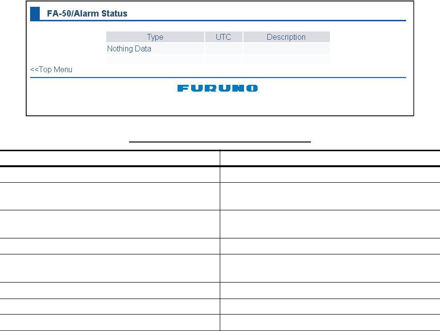
2.4 Alarm Status
The alarm status log shows the latest 25 dates and times alarms were violated. Click
“Alarm Status” on the main menu to show the alarm status log.
Note: When the transmitting is contuned more than one second, the equipment cut it off.
Description of Alarm Status indications
Alarm Status Indication Meaning
TX TX malfunction (and Error LED lights.)
CH1 TDMA RX1 Board trouble. TX stopped on cor-
responding TX channel.
CH2 TDMA RX2 Board trouble. TX stopped on cor-
responding TX channel
COG Invalid COG data.
EPFS No data from external navigator. Continued
operation possible.
HDG Invalid/nonexistent HDG data
L/L No L/L data
SOG Invalid SOG data
21
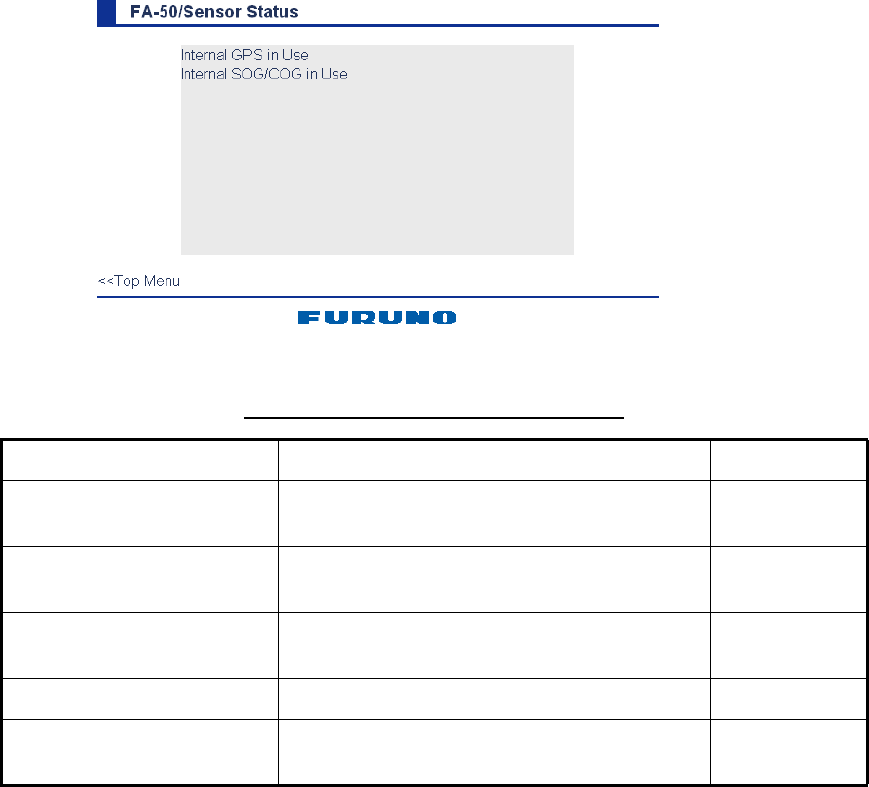
2.5 Sensor Status
The sensor status display provides information about sensors connected to the FA-50.
1. Show the main menu.
2. Click Sensor Status. The illustration below shows typical sensor status indications.
*1 Whichever navigator is in use.
*2 Displayed for 30 seconds after changing channel parameters. (It is necessary to
update the display.)
Description of sensor status indications
Indication Meaning Remarks
DGPS in use
(Internal/external)
DGPS currently in use See *1
GPS in use
(Internal/External)
GPS currently in use See *1
SOG/COG in use
(Internal/External)
SOG/COG currently in use
Heading valid Valid heading data
Channel Management
Parameters Changed
Channel parameters have been changed. See *2
22
3 MAINTENANCE,
TROUBLESHOOTING
3.1 Maintenance
Regular maintenance helps maintain good performance. Check the items listed below
at least monthly to help keep your equipment in good working order.
Maintenance table
Item Check point, remedy
Wiring Check that each cable and wire are securely fastened.
Refasten if necessary.
Ground Check ground point for rust. Clean if necessary.
VHF antenna Check VHF antenna and its cabling for damage.
Replace if necessary.
Cabinet Dust and dirt should be removed from the cabinet with a soft, dry
cloth. Do not use chemical-based cleaners; they can remove
paint and markings.
WARNING
Do not open the equipment
unless totally familiar with
electrical circuits and
service manual.
Only qualified personnel
should work inside the
equipment.
NOTICE
Do not apply paint, anti-corrosive sealant
or contact spray to coating or plastic
parts of the equipment.
Those items contain organic solvents that
can damage coating and plastic parts,
especially plastic connectors.
23
3.2 Replacing the Fuse
The fuse (4A) inside the FA-50 protects it from overcurrent and equipment fault. If the
unit cannot be powered, that is, the PWR (power) LED is off, the fuse may have blown.
If this happens, turn off the power to the FA-50, open the cover and check the fuse. If
the fuse has blown, find out the reason before replacing it. If it blows again after re-
placement, contact a FURUNO agent or dealer for advice.
3.3 Troubleshooting
The troubleshooting table below provides typical operating problems and the means
to restore normal operation. If you cannot restore normal operation, do not attempt to
check inside the receiver; there are no user serviceable parts inside the receiver.
Part Type Code No.
Fuse (4A) FGMB AC125V 4A PBF 000-157-482-10
Troubleshooting table
Symptom Problem Remedy
Receiver cannot be
powered.
Fuse inside the receiver may
have blown.
Replace the fuse.
Cannot receive. • VHF antenna may have
loosened.
• Antenna or its cabling may be
damaged.
• Rx channel is malfunctioning.
• Check if the antenna is firmly
fastened.
• Check the antenna and its
cabling for damage.
• Confirm the channel setting.
WARNING
Use the proper fuse.
Use of a wrong fuse can result in damage
to the equipment and cause fire.
24
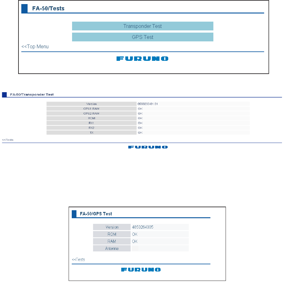
3.4 Diagnostics
The built-in diagnostic facility displays program version no. and checks RAM, ROM,
RX channels and GPS antenna for proper operation.
1. Open Internet Explorer and show the main menu.
2. Click Test to show the Test display.
3. Click “Transponder Test” or “GPS Test” to show the appropriate test screen.
Transponder test: The program version number appears on the first line. The CPU1
RAM and CPU2 RAM, ROM and the two RX channels and TX are checked for proper
operation, and the results are displayed as OK or NG (No Good). For any NG, try re-
setting the power and checking connections. If NG condition persists, contact your
dealer for advice.
GPS test: The program version number appears on the first line. The ROM, RAM and
connection with antenna (including power line), and the results are displayed as OK
or NG (No Good). For any NG, try resetting the power and checking connections. If
NG condition persists, contact your dealer for advice.
OK
AP-1
APPENDIX
Menu Tree
Initial Setup COM Port Setup Data Type
(
IEC61162
, IEC61162+P-sentence, Off)
Tx Speed (
38400 bps
)
RX Speed
(
Auto
, Manual (
4800 bps
, 38400 bps))
Network Setup MAC Address
IP Address (
172.031.024.003
)
Subnet Mask (
255.255.000.000
)
Gateway Address (
000.000.000.000
)
NavNet Port Number (
10000
)
Host Name (AIS0-AIS9,
AIS0
)
AIS Data Output (
Continuous
, Auto)
Ship Static Edit (Required a password.)
User Clear (Yes, No)
Own Vessel Data Own Static
(MMSI, Ship Name, Call Sign, Internal Antenna Position,
External Antenna Position, Ship Type,
Cargo Type (0-7,
7 Pleasure craft
))
View Channel
(RX1, RX2, Power, Region List, Group Assignment)
Message Send Message (shows pre-defined 10 messages,
1
)
Tx Log
Rx Log
Alarm Status
Sensor Status Transponder Test
(Version, CPU1RAM, CPU2RAM, ROM, RX1, RX2)
GPS Test (Version, ROM, RAM, Antenna)
For Service (Required a password.)

AP-2
VHF CHANNEL LIST
International mode
Ch No. Frequency (MHz) Ch No. Frequency (MHz)
1001 156.05 1088 157.425
1002 156.1 2001 160.65
1003 156.15 2002 160.7
1004 156.2 2003 160.75
1005 156.25 2004 160.8
6 156.3 2005 160.85
1007 156.35 2007 160.95
1018 156.9 8 156.4
1019 156.95 9 156.45
1020 157 10 156.5
1021 157.05 11 156.55
1022 157.1 12 156.6
1023 157.15 13 156.65
1024 157.2 14 156.7
1025 157.25 15 156.75
1026 157.3 16 156.8
1027 157.35 17 156.85
1028 157.4 2018 161.5
1060 156.025 2019 161.55
1061 156.075 2020 161.6
1062 156.125 2021 161.65
1063 156.175 2022 161.7
1064 156.225 2023 161.75
1065 156.275 2024 161.8
1066 156.325 2025 161.85
67 156.375 2026 161.9
68 156.425 2027 161.95
69 156.475 2028 162
70 156.525 2060 160.625
71 156.575 2061 160.675
72 156.625 2062 160.725
73 156.675 2063 160.775
74 156.725 2064 160.825
75 156.775 2065 160.875
76 156.825 2066 160.925
77 156.875 2078 161.525
1078 156.925 2079 161.575
1079 156.975 2080 161.625
1080 157.025 2081 161.675
1081 157.075 2082 161.725
1082 157.125 2083 161.775
1083 157.175 2084 161.825
1084 157.225 2085 161.875
1085 157.275 2086 161.925
1086 157.325 2087 161.975
1087 157.375 2088 162.025

AP-3
USA mode
(CH16 operates on 1W)
Ch No. Frequency (MHz) Ch No. Frequency (MHz)
1001 156.05 1088 157.425
2001 160.65
1003 156.15 2002 160.7
2003 160.75
1005 156.25 2004 160.8
6 156.3 2005 160.85
1007 156.35 2007 160.95
1018 156.9 8 156.4
1019 156.95 9 156.45
1020 157 10 156.5
1021 157.05 11 156.55
1022 157.1 12 156.6
1023 157.15 13 156.65
1024 157.2 14 156.7
1025 157.25 15 156.75
1026 157.3 16 156.8
1027 157.35 17 156.85
1028 157.4 2018 161.5
2019 161.55
1061 156.075 2020 161.6
2021 161.65
1063 156.175 2022 161.7
1064 156.225 2023 161.75
1065 156.275 2024 161.8
1066 156.325 2025 161.85
67 156.375 2026 161.9
68 156.425 2027 161.95
69 156.475 2028 162
70 156.525 2060 160.625
71 156.575 2061 160.675
72 156.625 2062 160.725
73 156.675 2063 160.775
74 156.725 2064 160.825
75 156.775 2065 160.875
76 156.825 2066 160.925
77 156.875 2078 161.525
1078 156.925 2079 161.575
1079 156.975 2080 161.625
1080 157.025 2081 161.675
1081 157.075 2082 161.725
1082 157.125 2083 161.775
1083 157.175 2084 161.825
1084 157.225 2085 161.875
1085 157.275 2086 191.925
1086 157.325 2087 161.975
1087 157.375 2088 162.025
A
P-4
Parts List
This equipment contains complex modules in which fault diagnosis and repair down to
component level are not practical (IMO A.694(17)/8.3.1). Only some discrete components
are used. FURUNO Electric Co., Ltd. believes identifying these components is of no value
for shipboard maintenance; therefore, they are not listed in the manual. Major modules
can be located on the parts location photo on page AP-5.
F U R U N O
Model FA-50
Unit
ELECTRICAL PARTS LIST
Blk.No.
NAME TYPE
PRINTED CIRCUIT BOARD
MAIN&TX&GPS 05P0814
POWER 05P0809
RX1 05P0808
RX2 05P0808
Tranponder
A
P-5
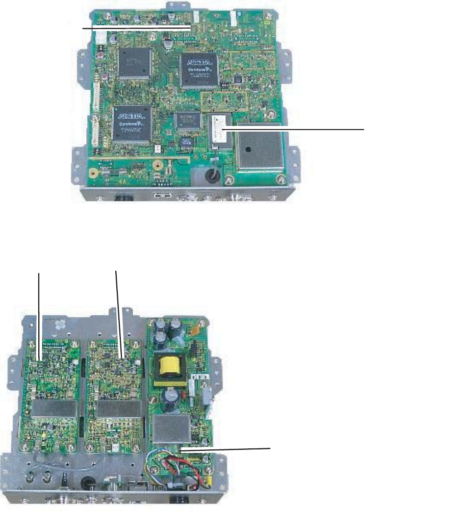
Parts Location
Transponder
GPS receiver
GN-8093
MAIN&TX&GPS Board
05P0814
Transponder, cover opened (upper)
RX1 Board
05P0808 RX2 Board
05P0808
POWER Board
05P0809
Transponder, cover removed (lower)

A
P-6
Digital Interface
Sentence data
Input sentences
ACK, AIQ, BBM, DSC, DSE, DTM, GBS, GGA, GLL, GNS, HDT, OSD, RMC, SSD, VBW,
VSD, VTG
Output sentences
ABK, ACA, ACS, ALR, TXT, VDM, VDO
Transmission interval
ABK: With each event
ACA, ACS: At RX/Switch information ion the region
ALR: 25 s during alarm, 2 min normally no alarm
TXT: Status is changed.
VDM: At RX VHF
VDO: 1 s
Load requirements as listener
Isolation: opto coupler
Input Impedance: 470 ohms
Max. Voltage: ±15 V
Threshold: 3 mA (In case of FURUNO device talker connection)
Output drive capability
Differential driver output
R=54 ohm 1.1 v min.
R=60 ohm 1.1 V min.
Driver short-circuit current
250 mA max.
Data transmission
Data format and protocol are transmitted in serial asynchronous form in accordance with
the standard referenced in 2.1 of IEC 61162-1. The first bit is a start bit and is followed by
data bits, least-significant-bit as illustrated below.
The following parameters are used:
Baud rate: 38.4 Kbps /4800 bps
Data bits: 8 (D7 = 0), parity none
Stop bits: 1
D0 D1 D2 D3 D4 D5 D6 D7
Start
bit
Stop
bit
Data bits
A
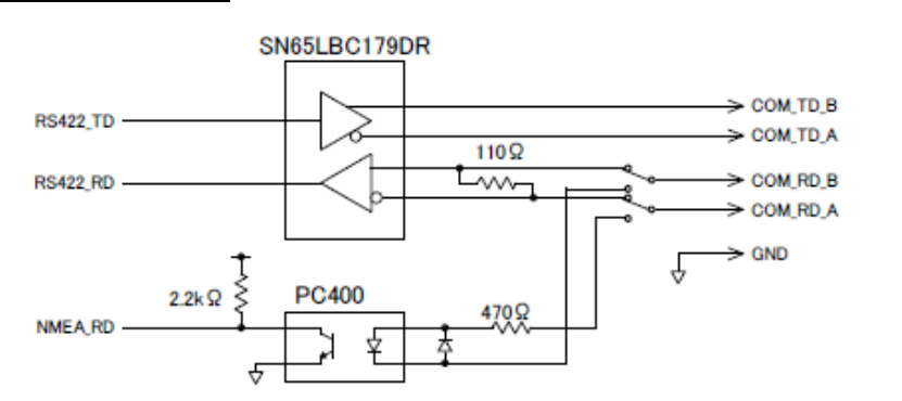
P-7
Serial interface I/O circuit
Input/Output Buffer

A
P-8
Sentence description
Input sentences
ACK - Acknowledge alarm
$--ACK,xxx*hh<CR><LF>
| +--------------------- 2
+------------------------ 1
1. Local alarm number(identifier)
2. Checksum
AIQ – AIS query
$--AIQ,ccc,*hh<CR><LF>
| |
| |
| +------------------------------ 2
+------------------------------------- 1
1. Query data
2. Checksum
BBM - UAIS broadcast binary message.
!--BBM,x,x,x,x,x.x,s--s,x*hh<CR><LF>
| | | | | | | |
| | | | | | | +--- 8
| | | | | | +------ 7
| | | | | +--------- 6
| | | | +------------- 5
| | | +---------------- 4
| | +------------------ 3
| +-------------------- 2
+---------------------- 1
1. Total number of sentences needed to transfer the message, 1 to 9
2. Message sentence number, 1 to 9
3. Sequential Message identifier, 0 to 9
4. AIS channel for broadcast of the radio message
5. VDL message number(8 or 14), see ITU-R M.1371
6. Binary data
7. Number of fill-bits, 0 to 5
8. Checksum
A
P-9
DSC – Digital selective calling information
$--DSC,xxxxxxxxxx,xx,xx,xx,xx,xx,x*hh<CR><LF>
| | | | | | | |
| | | | | | | +------- 8
| | | | | | +--------- 7
| | | | | +----------- 6
| | | | +-------------- 5
| | | +----------------- 4
| | +-------------------- 3
| +----------------------- 2
+------------------------------ 1
1. Maritime mobile service identity(MMSI)
(see note 3)
2. Format specifier(see note 2)
3. Categry(see note 2)
4. Nature of distress(see note 2)
5. First telecommand(see note 2)
6. Second telecommand(see note 2)
7. Acknowledgement type(see note 1)
8. Checksum
NOTES
1 Acknowledgement type:R - Acknowledge RQ
B - Acknowledge BQ
S - End of sequence of EOS
2 Last two digits of symbol number described in ITU-R M.493-6, Table 3.
3 MMSI of the called station for a DSC call to be initiated; MMSI of the
calling station in a received DSC call.
DSE – Expanded digital selective calling
$--DSE,x,x,a,xxxxxxxxxx,xx,c--c,.......,xx,c--c*hh<CR><LF>
| | | | | | | | | |
| | | | | | | | | +------- 8
| | | | | | | +--+----------- 7
| | | | | | +--------------------- 6
| | | | +--+--------------------------- 5
| | | +------------------------------------- 4
| | +-------------------------------------------- 3
| +---------------------------------------------- 2
+------------------------------------------------ 1
1. Total number of messages
2. Message number
3. Query/reply flag
4. Vessel MMSI
5. Data set '1'
6. Additional data sets
7. Data set 'n'
8. Checksum
A
P-10
DTM - Datum reference
$--DTM,ccc,a,x.x,a,x.x,a,x.x,ccc*hh<CR><LF>
| | | | | | | | |
| | | | | | | | +--- 7
| | | | | | | +------ 6
| | | | | | +---------- 5
| | | | +---+------------- 4
| | +---+------------------- 3
| +------------------------- 2
+---------------------------- 1
1. Local datum W84 - WGS84
W72 - WGS72
S85 - SGS85
P90 - PE90
999 - User defined
IHO datum code
2. Not used
3. Lat offset, min, N/S
4. Lon offset, min, E/W
5. Not used
6. Reference dattum W84 - WGS84
W72 - WGS72
S85 - SGS85
P90 - PE90
7. Checksum
GBS - GNSS satellite fault detection
$--GBS,hhmmss.ss,x.x,x.x,x.x,xx,x.x,x.x,x.x*hh<CR><LF>
| | | | | | | | |
| | | | | | | | +--------- 9
| | | | | | | +------------ 8
| | | | | | +---------------- 7
| | | | | +-------------------- 6
| | | | +----------------------- 5
| | | +--------------------------- 4
| | +------------------------------- 3
| +----------------------------------- 2
+------------------------------------------- 1
1. Not used
2. Expected error in latitude
3. Expected error in longitude
4. Not used
5. Not used
6. Not used
7. Not used
8. Not used
9. Checksum
A
P-11
GGA - Global positioning system (GPS) fix data
$--GGA,hhmmss.ss,llll.ll,a,yyyyy.yy,a,x,xx,x.x,x.x,M,x.x,M,x.x,xxxx*hh<CR><LF>
| | | | | | | | | | | | | | |
| | | | | | | | | | | | | | +-- 11
| | | | | | | | | | | | | +---- 10
| | | | | | | | | | | | +--------- 9
| | | | | | | | | | +---+------------ 8
| | | | | | | | +---+------------------ 7
| | | | | | | +------------------------- 6
| | | | | | +---------------------------- 5
| | | | | +------------------------------- 4
| | | +----+--------------------------------- 3
| +---+--------------------------------------------- 2
+------------------------------------------------------------- 1
1. Not used
2. Latitude, N/S
3. Longitude, E/W
4. GPS quality indicator
5. Not used
6. Not used
7. Not used
8. Not used
9. Not used
10. Not used
11. Checksum
GLL - Geographic position - latitude/longitude
$--GLL,llll.ll,a,yyyyy.yy,a,hhmmss.ss,A,a*hh<CR><LF>
| | | | | | | |
| | | | | | | +------- 6
| | | | | | +--------- 5
| | | | | +----------- 4
| | | | +---------------- 3
| | +------+----------------------- 2
+--+----------------------------------- 1
1. Latitude, N/S
2. Longitude, E/W
3. Not used
4. Status: A=data valid, V=data invalid
5. Mode indicator(see note)
6. Checksum
NOTE Positioning system Mode indicator:
A = Autonomous
D = Differential
E = estimated(dead reckoning)
M = Manual input
S = Simulator
N = Data not valid
The Mode indicator field supplements the Status field. The Status field shall be
set to V=invalid for all values of Operating Mode except for A=Autonomous and
D=Differential. The positioning system Mode indicator and Status field shall not
be null fields.
A
P-12
GNS - GNSS fixed data
$--GNS,hhmmss.ss,llll.ll,a,yyyyy.yy,a,c--c,xx,x.x,x.x,x.x,x.x,x.x*hh<CR><LF>
| | | | | | | | | | | | |
| | | | | | | | | | | | +--- 11
| | | | | | | | | | | +------ 10
| | | | | | | | | | +---------- 9
| | | | | | | | | +-------------- 8
| | | | | | | | +------------------ 7
| | | | | | | +---------------------- 6
| | | | | | +------------------------- 5
| | | | | +------------------------------ 4
| | | +-------+--------------------------------- 3
| +--+--------------------------------------------- 2
+------------------------------------------------------------- 1
1. Not used
2. Latitude, N/S
3. Longitude, E/W
4. Mode indicator
5. Not used
6. Not used
7. Not used
8. Not used
9. Not used
10. Not used
11. Checksum
HDT - Heading - true
$--HDT,x.x,T*hh<CR><LF>
| | |
| | +--------- 2
+----+----------- 1
1. Heading, degrees true
2. Checksum
A
P-13
OSD - Own ship data
$--OSD,x.x,A,x.x,a,x.x,a,x.x,x.x,a*hh<CR><LF>
| | | | | | | | | |
| | | | | | | | | +--------- 10
| | | | | | | | +----------- 9
| | | | | | | +-------------- 8
| | | | | | +------------------ 7
| | | | | +--------------------- 6
| | | | +------------------------ 5
| | | +--------------------------- 4
| | +------------------------------ 3
| +--------------------------------- 2
+------------------------------------ 1
1. Heading, degrees true
2. Heading status: A=data valid, V=data invalid
3. Vessel course, degrees true
4. Course reference, B/M/W/R/P(see note)
5. Vessel speed
6. Speed reference, B/M/W/R/P(see note)
7. Not used
8. Not used
9. Speed units, K(km/h) / N(Knots) / S(statute miles/h)
10. Checksum
NOTES - Reference systems(speed/course):
B = bottom tracking log
M = manually entered
W = water referenced
R = radar tracking(of fixed target)
P = positioning system ground reference
A
P-14
RMC - Recommended minimum specific GPS/TRANSIT data
$--RMC,hhmmss.ss,A,llll.ll,a,yyyyy.yy,a,x.x,x.x,xxxxxx,x.x,a,a*hh<CR><LF>
| | | | | | | | | | | | |
| | | | | | | | | | | | +--- 10
| | | | | | | | | | | +----- 9
| | | | | | | | | +--+------- 8
| | | | | | | | +--------------- 7
| | | | | | | +--------------------- 6
| | | | | | +------------------------- 5
| | | | +---+---------------------------- 4
| | +---+---------------------------------------- 3
| +--------------------------------------------------- 2
+---------------------------------------------------------- 1
1. UTC of position fix
2. Status: A=data valid, V=navigation receiver warning
3. Latitude, N/S
4. Longitude, E/W
5. Speed over ground, knots
6. Course over ground, degrees true
7. Date: dd/mm/yy
8. Not used
9. Not used
10. Checksum
NOTE Positioning system Mode indicator:
A = Autonomous
D = Differential
E = estimated(dead reckoning)
M = Manual input
S = Simulator
N = Data not valid
The Mode indicator field supplements the Status field. The Status field
shall be set to V=invalid for all values of Operating Mode except for
A=Autonomous and D=Differential. The positioning system Mode indicator
and Status field shall not be null fields.
A
P-15
SSD - UAIS ship static data
$--SSD,c--c,c--c,xxx,xxx,xx,xx,c, aa*hh<CR><LF>
| | | | | | | | |
| | | | | | | | +--9
| | | | | | | +--- 8
| | | | | | +----- 7
| | | | | +------- 6
| | | | +---------- 5
| | | +-------------- 4
| | +------------------ 3
| +---------------------- 2
+--------------------------- 1
1. Ship's Call Sign, 1 to 7 characters
2. Ship's Name, 1 to 20 characters
3. Pos. ref. point distance, "A," from bow, 0 to 511 Meters
4. Pos. ref. point distance, "B," from stern, 0 to 511 Meters
5. Pos. ref. point distance, "C," from port beam, 0 to 63 Meters
6. Pos. ref. point distance, "D," from starboard beam, 0 to 63 Meters
7. DTE indicator flag
8. Not used
9. Checksum
VBW - Dual ground/water speed
$--VBW,x.x,x.x,A,x.x,x.x,A,x.x,A,x.x,A*hh<CR><LF>
| | | | | | | | | | |
| | | | | | | | | | +--- 11
| | | | | | | | | +----- 10
| | | | | | | | +-------- 9
| | | | | | | +----------- 8
| | | | | | +-------------- 7
| | | | | +----------------- 6
| | | | +-------------------- 5
| | | +------------------------ 4
| | +--------------------------- 3
| +------------------------------ 2
+---------------------------------- 1
1. Not used
2. Not used
3. Not used
4. Longitudinal ground speed, knots
5. Transverse ground speed, knots
6. Status: ground speed, A=data valid V=data invalid
7. Not used
8. Not used
9. Not used
10. Not used
11. Checksum
A
P-16
VSD - UAIS voyage static data
$--VSD,x.x,x.x,x.x,c--c,hhmmss.ss,xx,xx,x.x,x.x*hh<CR><LF>
| | | | | | | | | |
| | | | | | | | | +--- 10
| | | | | | | | +------ 9
| | | | | | | +---------- 8
| | | | | | +------------- 7
| | | | | +---------------- 6
| | | | +----------------------- 5
| | | +------------------------------ 4
| | +----------------------------------- 3
| +--------------------------------------- 2
+------------------------------------------- 1
1. Type of ship and cargo category, 0 to 255
2. Maximum present static draught, 0 to 25.5 Meters
3. Persons on-board, 0 to 8191
4. Destination, 1-20 characters
5. Estimated UTC of arrival at destination
6. Estimated day of arrival at destination, 00 to 31(UTC)
7. Estimated month of arrival at destination, 00 to 12(UTC)
8. Navigational status, 0 to 15
9. Regional application flags, 0 to 15
10. Checksum
VTG - Course over ground and ground speed
$--VTG,x.x,T,x.x,M,x.x,N,x.x,K,a*hh<CR><LF>
| | | | | | | | | |
| | | | | | | | | +------- 6
| | | | | | | | +--------- 5
| | | | | | +---+----------- 4
| | | | +--+----------------- 3
| | +--+----------------------- 2
+-+----------------------------- 1
1. Course over ground, degrees true
2. Not used
3. Speed over ground, knots
4. Speed over ground, km/h
5. Mode indicator(see note)
6. Checksum
NOTE Positioning system Mode indicator:
A = Autonomous
D = Differential
E = estimated(dead reckoning)
M = Manual input
S = Simulator
N = Data not valid
The positioning system Mode indicator field shall not be a null field.

A
P-17
Output sentences
ABK - UAIS addressed and binary broadcast acknowledgement
$--ABK,xxxxxxxxx,a,x.x,x,x*hh<CR><LF>
| | | | | |
| | | | | +--- 6
| | | | +----- 5
| | | +------- 4
| | +---------- 3
| +------------- 2
+------------------- 1
1. MMSI of the addressed AIS unit
2. AIS channel of reception
3. Message type
4. Message sequence number
5. Type of acknowledgement
6. Checksum
ACA – AIS channel assignment message
$--ACA,x,IIII.I, a,yyyyy.y,a,IIII.I,a,yyyyy.y,a,x,xxxx,x,xxxx,x,x,x,a,x,hhmmss.s*hh<CR><LF>
1. Sequence number, 0 to 9
2. Region Northeast corner latitude - N/S
3. Region Northeast corner longitude - E/W
4. Region Southwest corner latitude - N/S
5. Region Southwest corner longitude - E/W
6. Transition Zone Size
7. Channel A
8. Channel A bandwidth
9. Channel B
10. Channel B bandwidth
11. Tx/Rx mode control
12. Power level control
13. Not used
14. In-use flag
15. Time of in-used change
15
14
13
12
11
10
9
8
7
6
5
4
3
2
1

A
P-18
ACS - Channel management information source
$--ACS,x,xxxxxxxxx,hhmmss.ss,xx,xx,xxxx*hh<CR><LF>
1. Sequence number, 0 to 9
2. MMSI of originator
3. UTC at receipt of regional operating settings
4. UTC day, 01- to 31
5. UTC month, 01 to 12
6. UTC year
6
5
4
3
2
1
ALR - Set alarm state
$--ALR,hhmmss.ss,xxx,A,A,c--c*hh<CR><LF>
| | | | | |
| | | | | +------------- 6
| | | | +----------------- 5
| | | +-------------------- 4
| | +---------------------- 3
| +------------------------- 2
+--------------------------------- 1
1. Time of alarm condition change, UTC
2. Local alarm number(identifier)
3. Alarm condition(A=threshold exceeded, V=not exceeded)
4. Alarm’s acknowledge state, A=acknowledged V=unacknowledged
5. Alarm’s description text
6. Checksum
TXT - Text transmission
$--TXT,xx,xx,xx,c--c*hh<CR><LF>
| | | | | |
| | | | | +--- 5
| | | +--+----- 4
| | +---------- 3
| +------------- 2
+---------------- 1
1. Total number of message, 01 to 99
2. Message number, 01 to 99
3. Text identifier
4. Text Message
5. Checksum
A
P-19
VDM - VHF data-link message
!--VDM,x,x,x,a,s--s,x*hh<CR><LF>
| | | | | | |
| | | | | | +--- 7
| | | | | +----- 6
| | | | +-------- 5
| | | +------------ 4
| | +-------------- 3
| +---------------- 2
+------------------ 1
1. Total number of sentences needed to transfer the message, 1 to 9
2. Message sentence number, 1 to 9
3. Sequential message identifier, 0 to 9
4. AIS channel
5. Encapsulated ITU-R M.1371 radio message
6. Number of fill-bits, 0 to 5
7. Checksum
VDO - UAIS VHF data-link own-vessel report
!--VDO,x,x,x,a,s--s,x*hh<CR><LF>
| | | | | | |
| | | | | | +--- 7
| | | | | +----- 6
| | | | +-------- 5
| | | +------------ 4
| | +-------------- 3
| +---------------- 2
+------------------ 1
1. Total number of sentences needed to transfer the message, 1 to 9
2. Message sentence number, 1 to 9
3. Sequential message identifier, 0 to 9
4. AIS channel
5. Encapsulated ITU-R M.1371 radio message
6. Number of fill-bits, 0 to 5
7. Checksum
FURUNO
FA-50
SPECIFICATIONS OF CLASS B AIS TRANSPONDER
FA-50
1 GENERAL
1.1 Type Class B AIS Transponder
1.2 RX capacity 2250 report/minute, 1channel
4500 report/minute, 2channel
1.3 RX system CSTDMA dual wave simultaneous reception
1.4 Synchronous framing Indirect synchronize from external oscillator
1.5 Operating mode Autonomous, Assigned, polled/interrogation response
1.6 Frequency switching Automatic
1.7 Prevention of abnormal TX Auto-suspend for detecting TX more than 1 second
1.8 Regulations IMO MSC.140 (76), IEC 62287-1, ITU-R M.1371-2,
DSC ITU R M.825-3, IEC 60945 ed.4 adopted
2 TRANSMITTER
2.1 Frequency range 156.025 MHz to 162.025 MHz (F1D)
2.2 Output power 1W/2W
2.3 Channel interval 25 kHz
2.4 Frequency deviation ±3 ppm or less
2.5 Transmit speed 9600 bps ± 50 ppm
2.6 Spurious Emission 9 kHz to 1 GHz, -36 dBm or less
1 GHz to 4 GHz, -30 dBm or less
3 AIS RECEIVER
3.1 Frequency range 156.025 MHz to 162.025 MHz (DSC: 156.525 MHz)
3.2 Oscillator frequency 1st local oscillator: f + (51.136/51.236 MHz)
2
nd local oscillator: 51.1/51.2 MHz
3.3 Intermediate frequency 1st: 51.136/51.236 MHz, 2nd: 36 kHz
3.4 Receiving system Double-conversion superheterodyne
3.5 Sensitivity -107 dBm (PER 20% or less)
3.6 Error at high input level -7 dBm
3.7 Co-channel rejection 10 dB
3.8 Adjacent channel selectivity 70 dB
3.9 Spurious response 70 dB (50 MHz to 520 MHz)
3.10 Inter-modulation 65 dB
3.11 Sensitivity suppression 86 dB (±5 MHz, ±10 MHz)
4 DSC RECEIVER (TIMESHARING SYSTEM)
4.1 Frequency 156.525 MHz (CH70)
4.2 Sensitivity -107 dBm or less
4.3 Error at high input level -7 dBm
SP - 1 E4442S01A
070828
FURUNO
FA-50
4.4 Co-channel rejection 10 dB
4.5 Adjacent channel selectivity 70 dB
4.6 Spurious response 70 dB
4.7 Inter-modulation 65 dB
4.8 Sensitivity suppression 84 dB
4 GPS RECEIVER
4.1 Receiving frequency 1575.42 MHz
4.2 Tracking code C/A code
4.3 Number of channel 12 channels parallel, 12 satellites
4.4 Position fixing method All in view, 8-state Kalman filter
4.5 Position accuracy 10 m approx., 95% of the time, (HDOP ≤ 4)
DGPS: 5m approx., 95% of the time
4.6 Tracking velocity 900 kts
4.7 Position fixing time Warm start: 36 s typical, Cold start: 43 s typical
4.8 Geoids WGS84
4.9 Position update interval 1 s
4.10 DGPS data correcting By AIS information
5 INTERFACE
5.1 COM I/O
Input: RS-422 (38.4kbps) / IEC61162-1 (4800bps)
ACK, BBM, DTM, GBS, GGA, GLL, GNS, HDT, OSD, RMC,
SSD, VBW, VSD, VTG, AIQ, DSC, DSE, PFEC
Output: RS-422 (38.4kbps)
ABK, ACA, ACS, ALR, VDM, VDO, TXT, PFEC
5.2 NETWORK Ethernet 10BASE-T/100BASE-TX
Input: ACK, BBM, DTM, GBS, GGA, GLL, GNS, HDT, OSD, RMC,
SSD, VBW, VSD, VTG, AIQ, DSC, DSE, PFEC
Output: ABK, ACA, ACS, ALR, VDM, VDO, TXT, PFEC
5.3 Function alarm LED indication, series data output
6 POWER SUPPLY
12-24 VDC: 2.0-1.0 A
7 ENVIRONMENTAL CONDITIONS
7.1 Ambient temperature
Antenna unit -30°C to +70°C
Transponder -15°C to +55°C
7.2 Relative humidity 93% at +40°C
7.3 Degree of protection
Antenna unit IPX6
SP - 2 E4442S01A
070828
FURUNO
FA-50
SP - 3 E4442S01A
070828
Transponder IP20
7.4 Bearing vibration IEC 60945
8 COATING COLOR
8.1 GPS antenna unit N9.5
8.2 Transponder N2.5
Aug.30'07 R.Esumi
OME-44420-Z