Furuno USA 9ZWFS1575 GMDSS SSB User Manual FS1575 2575 5075 OME Frontcover
Furuno USA Inc GMDSS SSB FS1575 2575 5075 OME Frontcover
Contents
- 1. users manual part 1A
- 2. users manaul part 1B
- 3. users manual part 2
- 4. users manual part 3
users manual part 1A
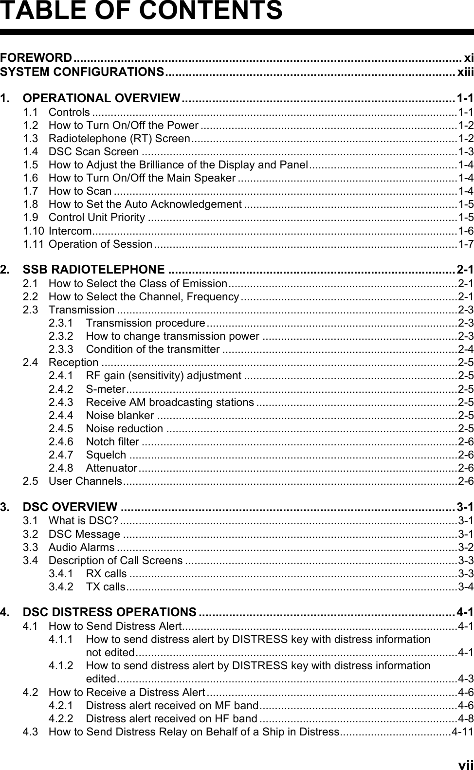
![SAFETY INSTRUCTIONSiiiThe TFT LCD is constructed using the latest LCD techniques, and displays 99.99% of its pixels. The remaining 0.01% of the pixels may drop out or blink, however this is not an indication of malfunction.About the TFT LCDWarning labels are attached to the equipment. Do not remove any label. If a label is missing or damaged, contact a FURUNO agent or dealer about replacement.Name: Warning Label 1Type: 86-003-1011-3Code No.: 100-236-233-10WARNING CAUTIONDo not operate the [DISTRESS] key except in case of a life-endangering situation on your vessel.Operating the [DISTRESS] key transmits the distress alert. Accidental transmission may prevent search and rescue operations for actual emergency. If the distress alert is accidentally transmitted, contact the nearest station to cancel the alert.If the distress alert is accidentally transmitted, contact the nearest coast station and inform them of the accidental transmission, providing the following data:a) Ship's nameb) Ship's call sign and DSC numberc) Position at time of transmissiond) Time of transmissionWARNING LABELSDo not apply strong pressure to the LCD, which is made of glass.Injury can result if the LCD breaks.Name: Warning LabelType: 14-055-4202-1Code No.: 100-245-221-10Name: High Temp Warning LabelType: 05-089-2142-0Code No.: 100-301-620-10](https://usermanual.wiki/Furuno-USA/9ZWFS1575.users-manual-part-1A/User-Guide-1777363-Page-5.png)
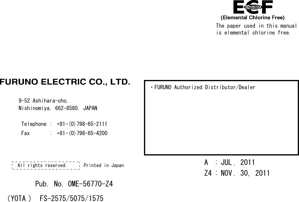
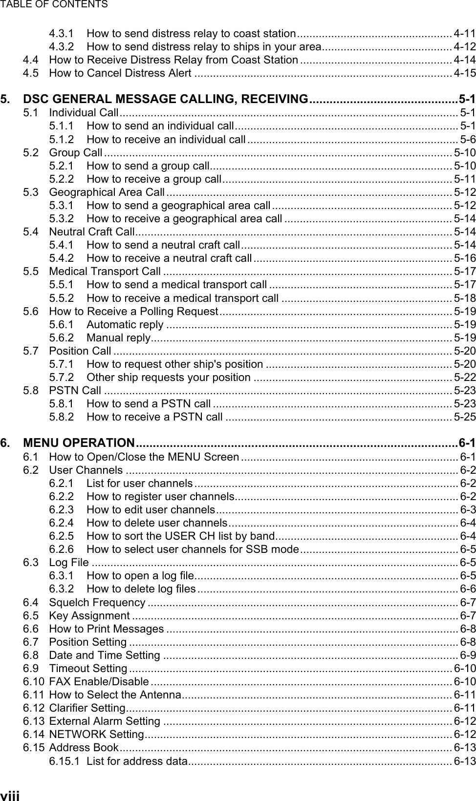
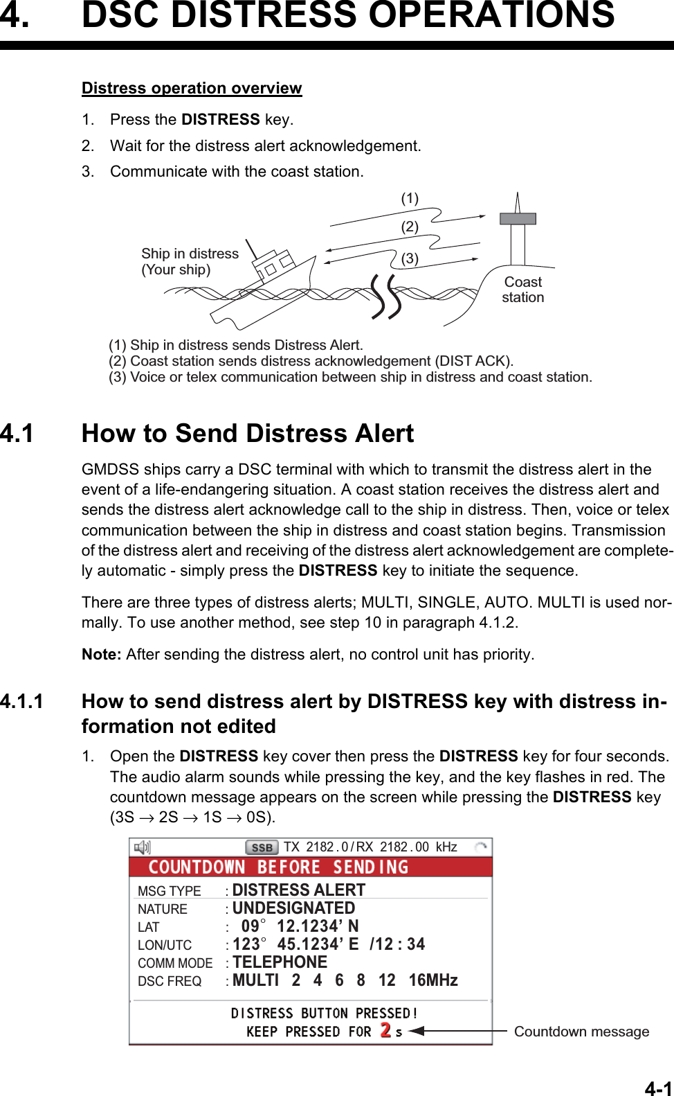
![ivDISTRESS ALERTHow to send distress alertBelow is the procedure for transmitting a distress alert via radiotelephone. Transmit the distress alert when a life-endangering situation occurs on your vessel.1. Open the DISTRESS key cover then press the DISTRESS key for four seconds. The following screen appears.2. When the message "Sending DISTRESS ALERT." appears on the screen, release the DIS-TRESS key. The audio alarm sounds for two seconds.After the distress alert has been sent, the following screens appear in order.3. The audio alarm sounds. Press the CANCEL key to silence the audio alarm.4. Communicate with the coast station via radiotelephone as below.a) Say “MAYDAY” three times.b) Say “This is ...” name of your ship and call sign three times.c) Give nature of distress and assistance needed.d) Give description of your ship (type, color, number of persons onboard, etc.).Note: If you do not receive the distress alert acknowledge call, the equipment automatically re-transmits the distress alert after 3 min 30 seconds to 4 min 30 seconds. Then awaits the distress alert acknowledge call. This is repeated until the distress alert is acknowledged.CountdownTX 2182 . 0 / RX 2182 . 00 kHzMSG TYPE : DISTRESS ALERTNATURE : UNDESIGNATEDLAT : 09° 12.1234’ NLON/UTC : 123° 45.1234’ E /12 : 34COMM MODE : TELEPHONEDSC FREQ : MULTI 2 4 6 8 12 16MHzWhen distress acknowledge call is received by coast stationPRINTTX 2182 . 0 / RX 2182 . 00 kHz09° 12.1234’ N/ 123° 45.1234’ E / 12 : 34CHANGE[ WAIT FOR ACK ]TX 2182 . 0 / RX 2182 . 00 kHz2, 4, 6, 8, 12, 16 MHz](https://usermanual.wiki/Furuno-USA/9ZWFS1575.users-manual-part-1A/User-Guide-1777363-Page-6.png)
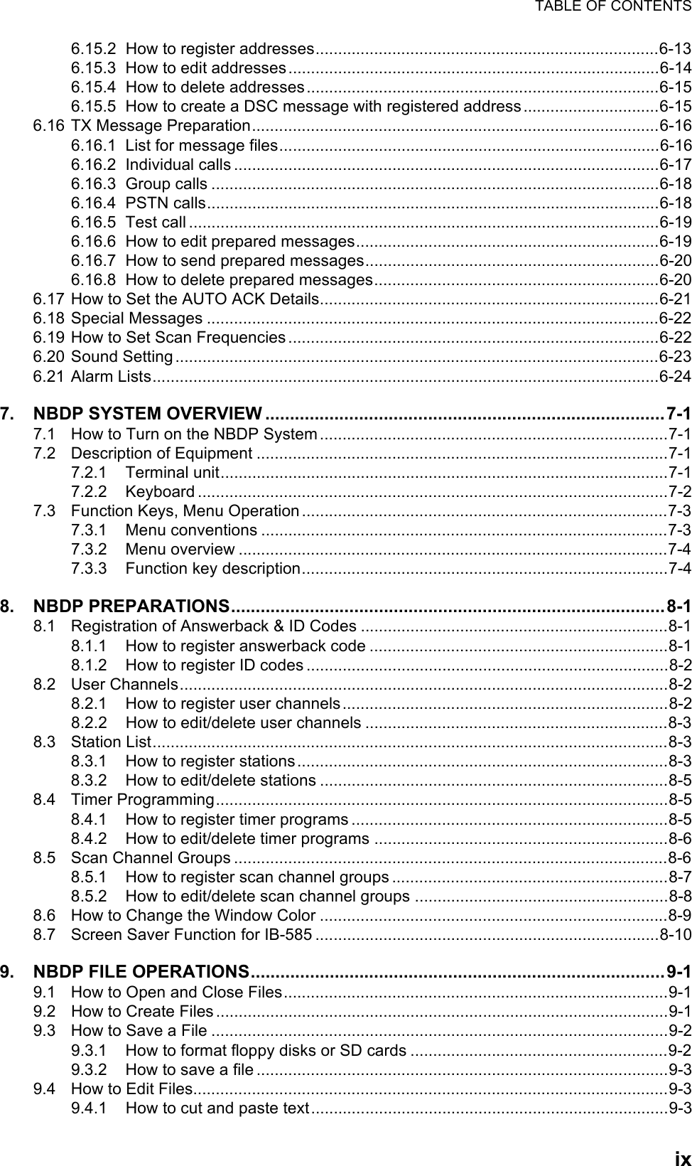
![DISTRESS ALERTvHow to cancel distress alertYou can cancel the distress alert while it is being sent or while waiting for its acknowledgement as follows.1. Rotate the ENTER knob to select [CANCEL] in the user options area then push the knob.The following message appears on the screen.2. Rotate the ENTER knob to select [Yes] then push the knob to cancel the distress alert.After transmitting the distress cancel call, the following message appears on the screen.3. Push the ENTER knob to erase the message. The screen for the selection of frequency ap-pears.PRINTTX 2182 . 0 / RX 2182 . 00 kHz09° 12.1234’ N/ 123° 45.1234’ E / 12 : 34CHANGE[ WAIT FOR ACK ]User options area2, 4, 6, 8, 12, 16 MHzPRINTTX 2182 . 0 / RX 2182 . 00 kHzDISTRESS CANCEL MODESELECT FREQUENCY AND : ENTER 2M-2182.0kHz 8M- 8291.0kHz 4M-4125.0kHz 12M-12290.0kHz 6M-6215.0kHz 16M-16420.0kHz](https://usermanual.wiki/Furuno-USA/9ZWFS1575.users-manual-part-1A/User-Guide-1777363-Page-7.png)
![DISTRESS ALERTvi4. Rotate the ENTER knob to select a frequency then push the knob. The following message appears on the screen.5. Communicate with all ships via radiotelephone referring to the message at step 4.6. Push the ENTER knob. The screen for the selection of frequency appears again. The frequen-cy marked by asterisk shows that the call cancellation by voice was completed for that fre-quency.7. Repeat steps 4 through 6 to cancel for ALL frequencies. When cancellation on all frequencies is completed, the options [Finish] and [Resend] appear.8. Rotate the ENTER knob to select [Finish] then push the knob.PRINTTX 2182 . 0 / RX 2182 . 00 kHzDISTRESS CANCEL MODESELECT FREQUENCY AND : ENTER 2M-2182.0kHz 8M- 8291.0kHz 4M-4125.0kHz 12M-12290.0kHz 6M-6215.0kHz 16M-16420.0kHz *PRINTTX 16420 . 0 / RX 16420 . 00 kHzDISTRESS CANCEL MODESELECT FREQUENCY AND : ENTER 2M-2182.0kHz 8M- 8291.0kHz 4M-4125.0kHz 12M-12290.0kHz 6M-6215.0kHz 16M-16420.0kHz *Finish Resend*****](https://usermanual.wiki/Furuno-USA/9ZWFS1575.users-manual-part-1A/User-Guide-1777363-Page-8.png)
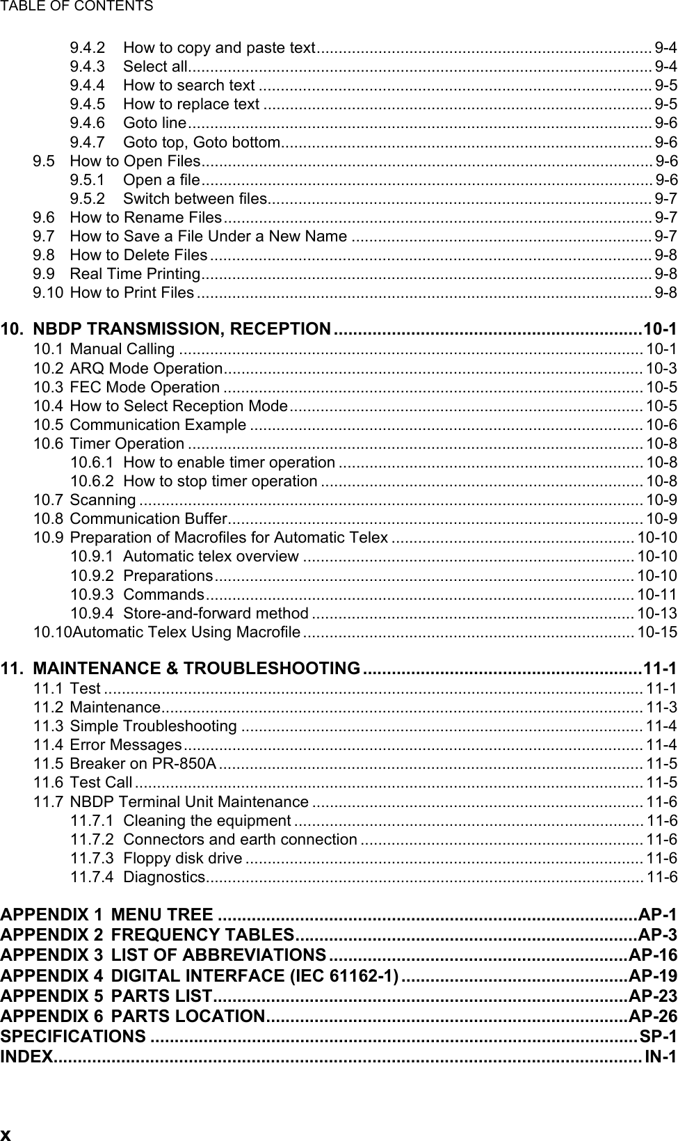
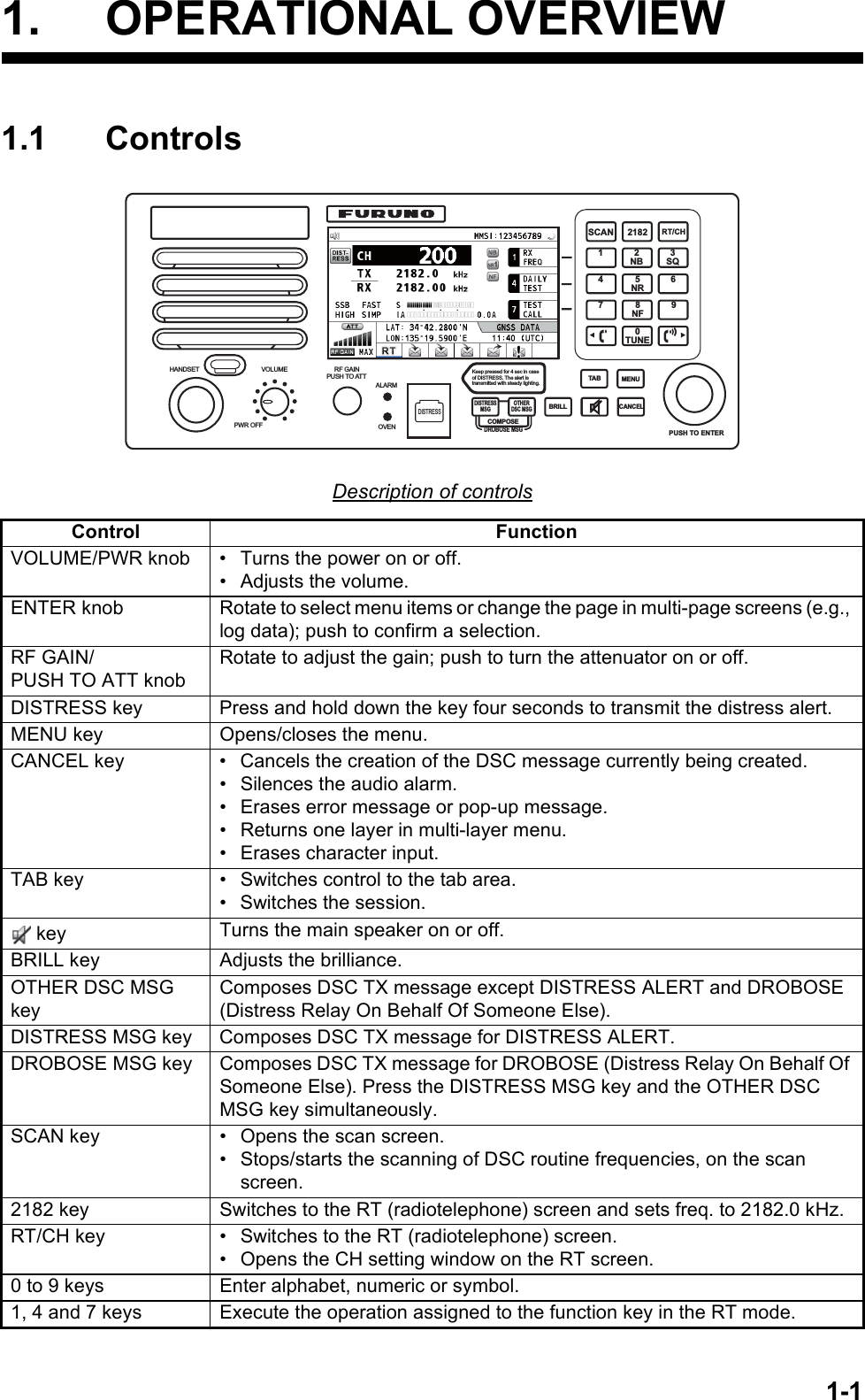
![1. OPERATIONAL OVERVIEW1-31.4 DSC Scan ScreenPress the SCAN key to show the DSC scan screen. This screen scans and receives the distress and routine frequencies.Indication MeaningMain speaker on or offCH ChannelTX TX frequency ( : while transmitting)RX RX frequencySSB/TLX/AM/FAX Class of emissionOFF/SLOW/FAST (AGC)Auto gain control ([OFF]: no adjustment, [SLOW]: low-speed, [FAST]: high-speed)HIGH/MID/LOW(1)/LOW2Output power ([LOW2]: FS-5075 only, minimum output power)SIMP/S-DUP/DUP Communication mode ([SIMP]: simplex, [S-DUP]: semi-duplex, [DUP]: full-duplex (only for FS-5075, option))IA/IC/VC/RF/VS Transceiver unit status ([IA]: antenna current, [IC]: collector current,[VC]: collector voltage, [RF]: RF output, [VS]: source voltage)S S-meter, displays the strength of received signal.NB Noise blanker ( :On, No indication: Off)NR2/NR1/OFF Noise reduction ( : High, : Low, No indication: Off)NF Notch filter ( : On, No indication: Off)SQ Squelch ( : On, No indication: Off)MMSI Own ship's ID (nine digits)LAT, LON Own ship's position (LAT: Latitude, LON: Longitude)GNSS UTC (universal time coordinated)ATT Attenuator ( : On, No indication: Off)RF GAIN Adjusted value of gainMaximum six distress and routine frequencies scanned.RX: Transceiver unit(WR2 shown when optional antenna for routine frequencies is installed.)135°19 . 5900 ' E34°42 . 2800 ' N](https://usermanual.wiki/Furuno-USA/9ZWFS1575.users-manual-part-1A/User-Guide-1777363-Page-19.png)
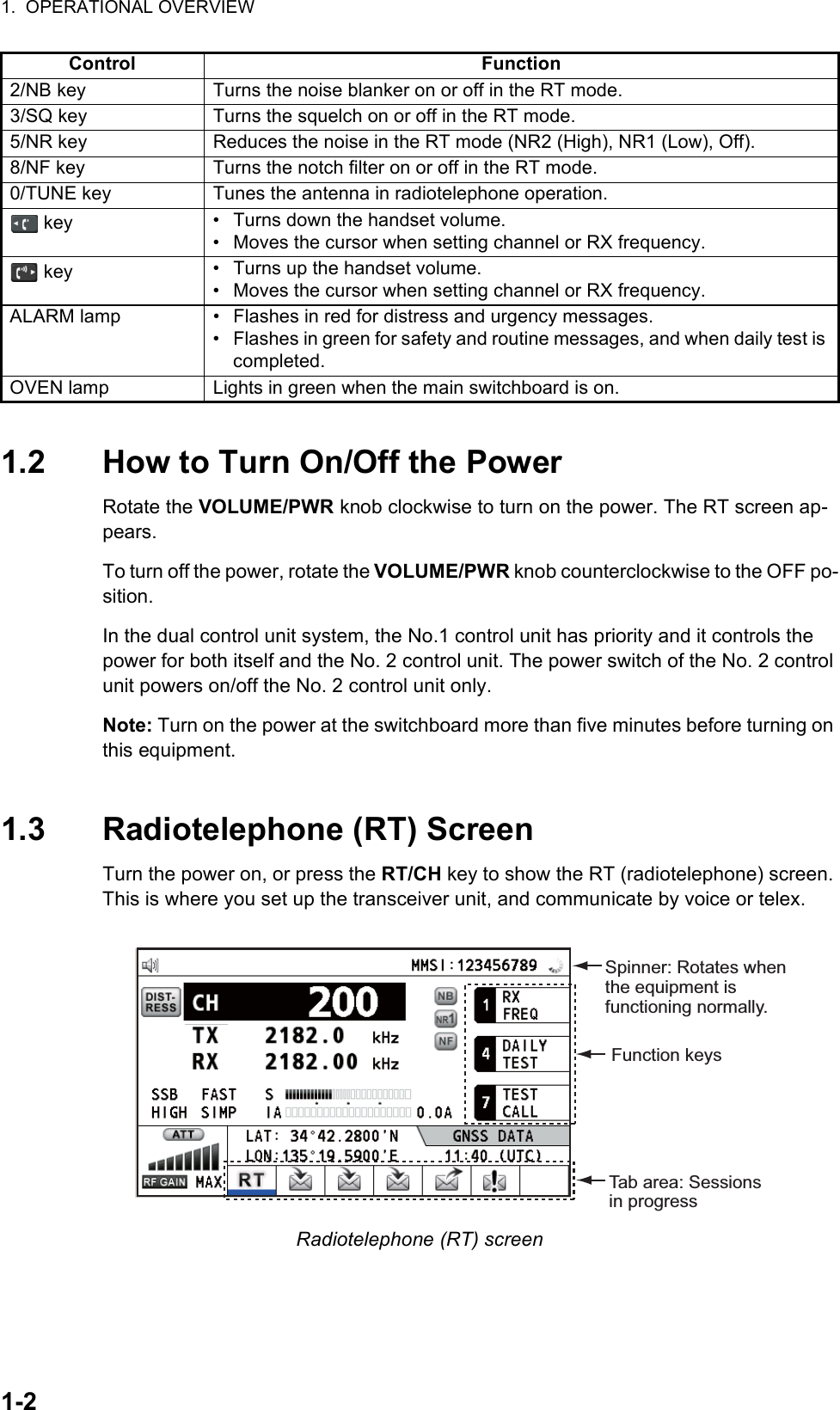
![1. OPERATIONAL OVERVIEW1-41.5 How to Adjust the Brilliance of the Display and PanelYou can adjust the brilliance of the display and the panel as follows:1. Press the BRILL key to show the [BRILL LEVEL SETUP] window.2. Press the 1 key to switch the [DAY/NIGHT] mode.3. To adjust the [DISPLAY] brilliance, rotate the ENTER knob or press the BRILL key.(Default setting: 17 for [DAY], 7 for [NIGHT])4. To adjust the [PANEL] brilliance, press the or key.(Default setting: 17 for [DAY], 12 for [NIGHT])5. Push the ENTER knob to save the settings and close the window. To cancel the settings, press the CANCEL key instead of the ENTER knob to close the window.Note 1: The equipment keeps values for [DAY] and [NIGHT] separately.Note 2: The window closes automatically when there is no operation for four seconds.Note 3: When you turn on the power with the display brilliance set to 0, the setting au-tomatically changes to 1.1.6 How to Turn On/Off the Main SpeakerYou can turn the main speaker (other than DSC communication, error, and key beep) on/off.1. Press the key to alternately disable or enable the main speaker.2. To adjust the volume of the main speaker, rotate the VOLUME/PWR knob (cw: volume up, ccw: volume down).1.7 How to ScanThe DSC screen scans multiple routine frequencies according to operator-set interval. For how to set frequency to scan, see section 6.19.Note that voice and telex communication are not available when scanning.Speaker ON Speaker OFF](https://usermanual.wiki/Furuno-USA/9ZWFS1575.users-manual-part-1A/User-Guide-1777363-Page-20.png)
![1. OPERATIONAL OVERVIEW1-51. Press the SCAN key to show the DSC scan screen. Scanning starts. When re-ceiving the appropriate frequency signal, the scanning stops, and the frequency is highlighted and flashes.2. Press the SCAN key again to stop scanning the routine frequencies.Note: You can not stop the scanning manually for the distress alert.3. Rotate the ENTER knob to move the cursor to the desired routine frequency which you want to watch. You can scan only the frequency selected by cursor.4. Press the SCAN key to restart the scanning.Note: When scanning starts, the active session (refer to section 1.11) is automatically put on hold.1.8 How to Set the Auto AcknowledgementIndividual, PSTN (public switched telephone network), position, polling and test calls can be acknowledged automatically or manually. This is set on the [ACK SETTINGS] in the [DSC] menu (see section 6.17).Note: When own ship's communication is high priority, set to manual acknowledge-ment.The auto acknowledgement is not sent in the following cases:• Other session is active (except individual call).• There are RT or DSC sessions (for individual call).• Channel is in use.• ECC is NG (No Good).Note: The auto acknowledgement for the individual call is sent only when the pro-posed channel or communication mode is not available.1.9 Control Unit PriorityIf you operate the No.1 control unit while the No.2 control unit is being operated, the right to operate is shifted to the No.1 control unit. The control unit not having priority shows the following:• The unit name currently in use: No.1 control unit, No.2 control unit or NBDP• The ongoing operation: Composing messages, Transmitting, CommunicatingThe control unit which you operate has priority in the following conditions:• The handset goes OFF HOOK.• Display the menus or setting windows.• Display each function screen (for example, Log).• Press a key or rotate a knob. (The priority is lost after four seconds.)• NBDP is communicating.](https://usermanual.wiki/Furuno-USA/9ZWFS1575.users-manual-part-1A/User-Guide-1777363-Page-21.png)
![1. OPERATIONAL OVERVIEW1-61.10 IntercomThe built-in intercom permits voice communications between two control units.CallingYou can call over the intercom in on or off hook condition.1. Press the MENU key.2. Rotate the ENTER knob to select [INTERCOM] then push the knob. The pop-up for calling appears and the called party's control unit rings. To cancel calling, press the CANCEL key.3. When the called party picks up their handset, the pop-up for calling disappears and the INTERCOM CONNECTED screen appears. Start communications.Note: You do not have to press the PTT switch to communicate.4. If needed, adjust the handset volume with or key.5. Hang up the handset or press the CANCEL key to turn the intercom off. The last-used screen or the RT screen appears.Answering1. The control unit rings, and both the pop-up for calling and a message, which sug-gests you to pick up the handset, appear. To cancel reply, press the CANCEL key.2. Pick up the handset, and the alarm stops. The pop-up for calling disappears and the INTERCOM CONNECTED screen appears. Start communications.3. Hang up the handset or press the CANCEL key to turn the intercom off. The last-used screen or the RT screen appears.](https://usermanual.wiki/Furuno-USA/9ZWFS1575.users-manual-part-1A/User-Guide-1777363-Page-22.png)
![1. OPERATIONAL OVERVIEW1-71.11 Operation of SessionDescription of sessionThere are two types of sessions: RT session and DSC session. When a session starts, the appropriate icon for the session appears in the tab area.How to finish a single sessionRT session1. Press the TAB key to select the RT icon in the tab area.2. Rotate the ENTER knob to select [QUIT] then push the knob.DSC sessionThe cursor is in the tab area when the DSC session starts. Rotate the ENTER knob to select [QUIT] then push the knob.RT session DSC sessionsTab areaStep 1: Press the TAB key to select the RT icon.Step 2: Rotate the ENTER knob to select [QUIT]. [SELECT AN ACK] ELAPSED TIME: INDIVIDUAL MSG 00H00M58SFROM : 123456789 CAPTAIN_2575COMM MODE : TELEPHONECOMM FREQ : TX 2170.0 /RX 2170.0 kHzINFO PRINT HOLD QUITACCEPT UNABLE PROPOSETX 2177.0/ RX 2177.00 kHzRotate the ENTER knob to select [QUIT].](https://usermanual.wiki/Furuno-USA/9ZWFS1575.users-manual-part-1A/User-Guide-1777363-Page-23.png)
![1. OPERATIONAL OVERVIEW1-8How to start a new sessionWhen another session is active:• When sending the distress alert, all sessions except the distress alert TX session automatically close then the distress alert TX session starts.• When doing an RT session or sending a non-distress DSC message, the currently active session is put on hold then the RT session or non-distress DSC message TX session starts.• When receiving a DSC message, its session is put on hold.When no other session is active:• When sending the distress alert, all sessions except the distress alert TX session automatically close then the distress alert TX session starts.• When sending a non-distress DSC message, its session becomes the active ses-sion.How to switch sessionsWhen one session is active and another message arrives, a new session for the re-ceived message does not start automatically. Only one session can be active. For ex-ample, when you are transmitting a DSC message and another message arrives, the option [ACTIVE] appears to indicate the start of a new session. [SELECT AN ACK] INDIVIDUAL MSG ELAPSED TIME : 00H00M58SFROM : 123456789 CAPTAIN_2575COMM MODE : TELEPHONECOMM FREQ : TX 2170.0 / RX 2170.0 kHzACTIVE INFO PRINT QUITTX 2182.0/ RX 2182.00 kHzRTPress the TAB key to move the cursor to the tab area.To select a session, press the TAB key. The cursor is here. [RT : SSB] CH : 200 TX : 2182.0 kHz RX : 2182.00 kHzInformation for the session selected by cursor. With [ACTIVE] selected, push the ENTER knob to switch the active session. To switch the option for the session (ACTIVE, INFO, PRINT, QUIT), rotate the ENTER knob. User options areaTab area(Continued on next page)Information for the session underlined in blue (RT in this case)](https://usermanual.wiki/Furuno-USA/9ZWFS1575.users-manual-part-1A/User-Guide-1777363-Page-24.png)
![1. OPERATIONAL OVERVIEW1-9How to close a sessionTo manually close a session, select it with the TAB key. Rotate the ENTER knob to select [QUIT] in the user options area then push the knob. The session icon disap-pears from the tab area.When there is no operation for specific time (see section 6.9), the inactive session is automatically closed.Processing when the number of session is maximumA maximum of seven sessions can be displayed in the tab area. If a seventh session starts, the following message appears on the screen. Press the CANCEL key to close the message. Close a session to make space for the new session.If the eighth session is for sending a distress alert, all sessions except that session automatically close, and the session starts. [SELECT AN ACK] ELAPSED TIME: INDIVIDUAL MSG 00H01M12SFROM : 123456789 CAPTAIN_2575COMM MODE : TELEPHONECOMM FREQ : TX 2170.0 /RX 2170.0 kHzINFO PRINT HOLD QUITACCEPT UNABLE PROPOSETX 2177.0/ RX 2177.00 kHzRTOnly the screen for the selected session appears. [WAIT FOR ACK] INDIVIDUAL MSG ELAPSED TIME : 00H05M24STO : 987654321 CAPTAIN_5075COMM MODE : TELEPHONECOMM FREQ : TX 2170.0 / RX 2170.0 kHzACTIVE INFO PRINT QUITTX 2177.0/ RX 2177.00 kHzRTTo finish this session, rotate the ENTER knob to select [QUIT] then push the knob.NO ACTIVEThe icon disappears.(Continued from previous page)Note: When waiting for the ACK, that is, the session is in progress, the confirmation message appears. Rotate the ENTER knob to select [YES] or [NO] then push the knob.](https://usermanual.wiki/Furuno-USA/9ZWFS1575.users-manual-part-1A/User-Guide-1777363-Page-25.png)
![2-12. SSB RADIOTELEPHONEYou can do SSB communications from any screen which displays the communication frequency.2.1 How to Select the Class of EmissionYou can select the class of emission from among the following:• [SSB]: Single Sideband• [TLX]: Telex• [AM]: AM (RX only)• [FAX]: FAX (RX only. Connect a FAX to this equipment to print FAX messages.)At the RT screen, select the class of emission as follows:1. Rotate the ENTER knob to highlight the class of emission (default: [SSB]) then push the knob. When you rotate the ENTER knob clockwise, the cursor moves from [CH] downward.2. Rotate the ENTER knob to select the class of emission desired then push the knob. AGC is automatically turned on or off according to the class of emission.3. You can change AGC as below.1) Rotate the ENTER knob to select the AGC mode indication then push the knob.2) Rotate the ENTER knob to select [OFF], [SLOW] or [FAST] then push the knob.2.2 How to Select the Channel, FrequencySelect the channel or transmitting/receiving frequency to use for the SSB.Note: To set the SSB radiotelephone to 2182 kHz/J3E, press the 2182 key.• [SSB]: [FAST] • [TLX], [FAX]: [OFF] • [AM]: [SLOW]Class of emissionAGC mode (Automatic Gain Control)This icon appears when the frequency is for distress.](https://usermanual.wiki/Furuno-USA/9ZWFS1575.users-manual-part-1A/User-Guide-1777363-Page-27.png)
![2. SSB RADIOTELEPHONE2-2Channel1. Rotate the ENTER knob to select [CH] on the RT screen then push the knob. You can also show the channel setting window by pressing the RT/CH key.2. A channel can be entered directly with the numeric keys, or by using the ENTER knob. See below for details.Enter channel with the numeric keys:Use the numeric keys to enter channel then push the ENTER knob.Select band and band channel with the ENTER knob:1) Use the or key to place the cursor in the band or band channel position, whichever you want to change.2) Rotate the ENTER knob to set band or band channel desired.3) Push the ENTER knob to close the setting window.Frequency1. Rotate the ENTER knob to select [TX] or [RX] then push the knob.2. Enter frequency by one of the methods below.Enter frequency with the numeric keys:Use the numeric keys to enter frequency then push the ENTER knob. For exam-ple, to enter 2161 kHz, key in 2, 1, 6, 1, 0. (Note: Keying in 2-1-6-1 sets 216.1 kHz.) Be sure to include zero for 100 Hz place.Select frequency with the ENTER knob (for RX only):1) Use the or key to change the range which the cursor covers.2) Rotate the ENTER knob to set frequency desired.3) Push the ENTER knob to close the setting window.Note: When TX and RX frequencies are different, first enter TX then enter RX.Channel setting windowCursor position for selection of band channel 2 0 0Cursor position for selection of band 2 0 02 4 6 8 12 16 18 22 25 01 02----- 029ITU band User bandSetting RangeITU Band (SSB, TLX): 2/4/6/8/12/16/18/22/25ITU Band (CW): 4/6/8/12/16/22/25User Band: 01-029 (First zero is necessary)ITU Channel (SSB): 00 - XXITU Channel (TLX): 000 - XXXITU Channel (CW): 001 - XXXUser Channel: 01 - 992182.0TX RX2182.00](https://usermanual.wiki/Furuno-USA/9ZWFS1575.users-manual-part-1A/User-Guide-1777363-Page-28.png)
![2. SSB RADIOTELEPHONE2-32.3 TransmissionAfter selecting the class of emission and frequency, you can transmit by pressing the PTT switch on the handset.2.3.1 Transmission procedureMaximum transmission power is achieved only when the antenna impedance and transmitter impedance match each other. Because the antenna impedance changes with frequency, antenna impedance matching with the transmitter impedance is done with the antenna coupler. The antenna coupler automatically tunes the transmitter to a wide range of different antenna lengths. The available range is;• Wire antenna 10 to 18 meters long (horizontal part)• Whip antenna eight meters long (Horizontal feeder is two meters or longer.)• Whip antenna 10 meters longTo initiate the tuning, do the following:1. Press the PTT switch on the handset. Tuning is automatically adjusted at first transmission after frequency is changed. For manual tuning, press the 0/TUNE key on the RT screen. If tuning fails, the message "TUNE NG" appears and the output power is automatically set to [LOW] (for FS-1575/2575) or [LOW2] (for FS-5075).2. Hold the handset close to your mouth, press the PTT switch and speak clearly.Note: When tuning is initiated in the two control unit system, the screen of the idle con-trol unit shows "OCCUPIED (CONTROLLER 1 (or 2))". In this case, only the DISTRESS key is operative on the idle control unit.2.3.2 How to change transmission powerTo minimize possible interference to other stations, reduce the transmission power. This should be done when using the transceiver in a harbor, near the shore or close to communication partner (other ship).1. Rotate the ENTER knob to select [HIGH], [MID], [LOW] (for FS-1575/2575), [LOW1] (for FS-5075) or [LOW2] (for FS-5075) (whichever is displayed), then push the knob.HIGH MID LOW1LOW2HIGH MID LOWFor FS-5075For FS-1575/2575135°19 . 5900 ' E34°42 . 2800 ' N](https://usermanual.wiki/Furuno-USA/9ZWFS1575.users-manual-part-1A/User-Guide-1777363-Page-29.png)
![2. SSB RADIOTELEPHONE2-42. Rotate the ENTER knob to select the option desired then push the knob.Note: The temperature of the power amplifier is monitored. When its temperature ris-es above a certain temperature, output power is automatically reduced.2.3.3 Condition of the transmitterWhile transmitting, you can display [IA] (antenna current), [IC] (collector current), [VC] (collector voltage), [RF] (RF output) or [VS] (source voltage) on the RT screen.1. Rotate the ENTER knob to select [IA], [IC], [VC], [RF] or [VS] (whichever is dis-played) then push the knob.2. Rotate the ENTER knob to select the option desired then push the knob.Check the transmission powerDuring transmission, the IA bar deflects according to the current being fed from the antenna coupler to the antenna feeder. The unit of readout is amperes. The antenna current varies with the effective antenna impedance. The reading differs by the fre-quency and antenna length. The output power is proportional to the square of an an-tenna current.FS-1575/2575 FS-5075[HIGH] No reducing[MID] 125 Wpep 350 Wpep[LOW] 90 Wpep -[LOW1] - 200 Wpep[LOW2] - 110 WpepAntenna current](https://usermanual.wiki/Furuno-USA/9ZWFS1575.users-manual-part-1A/User-Guide-1777363-Page-30.png)
![2. SSB RADIOTELEPHONE2-52.4 ReceptionCheck if the class of emission and receiving frequency are set properly. If necessary, set them again referring to sections 2.1 and 2.2.2.4.1 RF gain (sensitivity) adjustmentIn normal use the sensitivity should be set for maximum. If the audio on the received channel is unclear or interfered with other signals, adjust (usually reduce) sensitivity to improve clarity.Rotate the RF GAIN/PUSH TO ATT knob to adjust gain (sensitivity). The setting value is displayed at the lower left-hand side of the screen, with analog and digital indications.2.4.2 S-meterThe S-meter shows relative signal strength coming into the receiver front end.2.4.3 Receive AM broadcasting stations1. If the RT screen is not displayed, press the RT/CH key to display the RT screen.2. Rotate the ENTER knob to select the current class of emission then push the knob.3. Rotate the ENTER knob to select [AM] then push the knob (see section 2.1).4. Rotate the ENTER knob to select [RX] then push the knob.5. Enter RX frequency with the numeric keys then push the ENTER knob (see "Fre-quency" in section 2.2).2.4.4 Noise blankerThe noise blanker removes pulse noise. Press the 2/NB key on the RT screen to turn the noise blanker on and off alternately. When the noise blanker function is active, is displayed on the RT screen.2.4.5 Noise reductionThe noise reduction circuit analyzes speech component and noise component, and reduces only noise component. Press the 5/NR key on the RT screen. Each time you press the 5/NR key, the effect of noise reduction changes in the sequence of ([NR2] S-meter](https://usermanual.wiki/Furuno-USA/9ZWFS1575.users-manual-part-1A/User-Guide-1777363-Page-31.png)
![2. SSB RADIOTELEPHONE2-6(High) → [NR1] (Low) → Off). When the noise reduction function is active, or is displayed on the RT screen.2.4.6 Notch filterThe notch filter removes mixed CW (continuous wave) or beat signal interference. Press the 8/NF key on the RT screen to turn the notch filter on and off alternately. When the notch filter function is active, is displayed on the RT screen.2.4.7 SquelchSquelch on/offThe squelch mutes the audio output in the absence of an incoming signal. Press the 3/SQ key on the RT screen to turn the squelch on and off alternately. When radio noise is too jarring during stand-by condition, it can be muted by activating the squelch. When the squelch function is active, is displayed on the RT screen.Squelch frequencyTo adjust the squelch frequency, see section 6.4.2.4.8 AttenuatorThe attenuator reduces total gain and prevents saturation. Push the RF GAIN/PUSH TO ATT knob on the RT screen to turn the attenuator on and off alternately. When the attenuator function is active, is displayed on the RT screen.2.5 User ChannelsThe [USER CH] menu provides for registration of user TX and RX channels, where permitted. For further details, contact your dealer. See section 6.2 for the procedure.NOTICEFURUNO will assume no responsibility for the disturbance caused by the unlawful or improper setting of user channels.](https://usermanual.wiki/Furuno-USA/9ZWFS1575.users-manual-part-1A/User-Guide-1777363-Page-32.png)
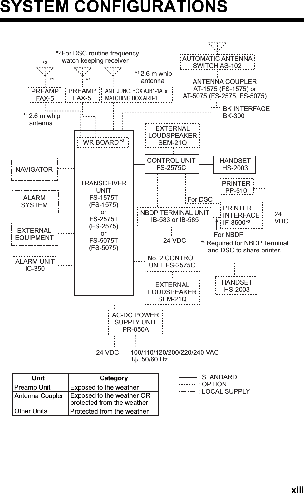
![3-13. DSC OVERVIEW3.1 What is DSC?DSC is an acronym meaning Digital Selective Calling. It is a digital distress and gen-eral calling system in the MF and HF bands used by ships for transmitting distress alerts and general calls and by coast stations for transmitting the associated acknowl-edgements.For DSC distress, safety and urgency callings in the MF and HF bands, the frequen-cies are 2187.5, 4207.5, 6312.0, 8414.5, 12577.0, and 16804.5 kHz.3.2 DSC MessageDSC calls are roughly divided in two groups: distress messages and general (safety, urgency and routine) messages. Below are the types of DSC messages.*SPECIAL MSG: To send these messages, set [SPECIAL MSG] to [ABLE]. See section 6.18.Call DescriptionDISTRESS ALERT Your ship sends distress message.DISTRESS RELAY AREAYour ship relays distress call to all ships in a specific geographical area.DISTRESS RELAY INDIVIDUALYour ship relays distress call to a coast station.MEDICAL MSG* Inform areas that your ship is carrying medical supplies.NEUTRAL MSG* Inform areas that your ship is not a participant in armed conflict.INDIVIDUAL MSG Call to a specific address.PSTN MSG Call over Public Switched Telephone Network (PSTN).TEST MSG Send test signal to a station to test your station's functionality.GROUP MSG Call to a specific group.AREA MSG Call to all ships in a specific geographical area.POSITION MSG Your ship requests position of other ships.POLLING MSG Confirm if your ship is within communicating range with other ships. (Re-ceive and answer only)Distress, Safety, Urgency DSC calls Routine DSC CallOptionRoutine DSC CallTRANSCEIVER UNIT CONTROL UNITDistress, Safety, Urgency and Routine DSC Calls](https://usermanual.wiki/Furuno-USA/9ZWFS1575.users-manual-part-1A/User-Guide-1777363-Page-33.png)
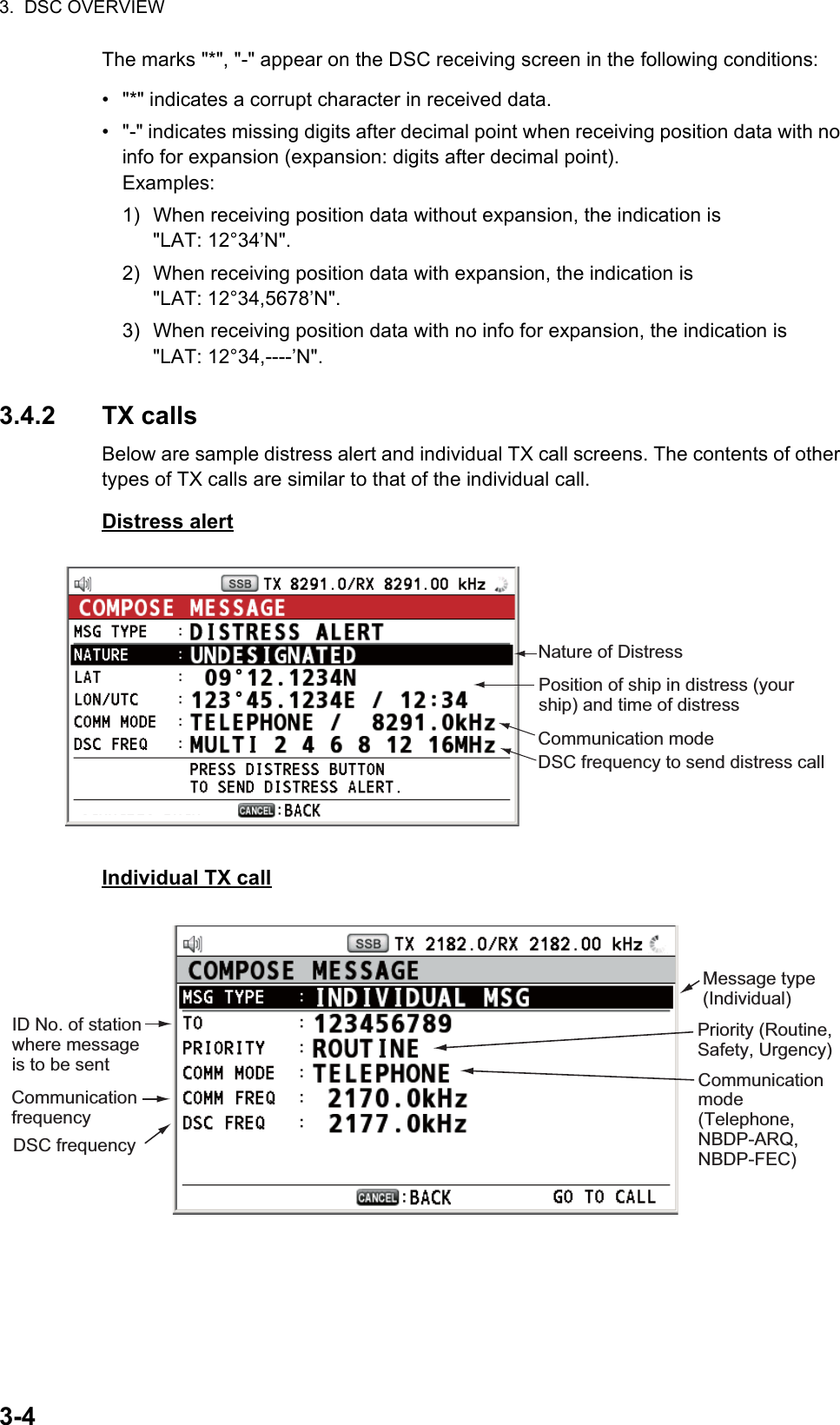
![3. DSC OVERVIEW3-33.4 Description of Call ScreensThis section provides the information necessary for interpreting the receive and send call screens.3.4.1 RX callsBelow are sample distress alert and individual RX call screens. The contents of other types of RX calls are similar to that of the individual call.Distress alertIndividual RX callDistress alert sent 2200 Hz, continuous (2 seconds)Own ship position not updated 2000 Hz (250 ms) and 0 Hz (500 ms)Distress alert call received 2200 Hz and 1300 Hz (250 ms)Distress relay call received 2200 Hz and 1300 Hz (250 ms)Distress relay ack call received 2200 Hz (500 ms) and 1300 Hz (500 ms)Distress ack call received 2200 Hz (500 ms) and 1300 Hz (500 ms)Urgency call received 2200 Hz and 0 Hz (250 ms)Urgency ack call received 2200 Hz and 0 Hz (500 ms)Alarm Frequency (interval)Working frequency to useCall typeElapsed time since distress alert receivedID No. (MMSI) of ship in distressCommunication mode and suggested channel Available user options Session in progressRF gainSpeaker iconDSC frequencyPosition of ship in distressNature of distressDistance to ship in distress34°42.2800’N/135°19.5900’W/14:12Working frequency to useSpeaker iconElapsed time since call receivedID No. (MMSI) of ship sending this messageCommunication frequencyRF gainAvailable user options Communication modeSession in progress Call type[SELECT AN ACK] INDIVIDUAL MSGELAPSED TIME: 00H00M16SFROM :COMM MODE :COMM FREQ :123456789TELEPHONETX 2170.0/RX 2170.0 kHzSACCEPT BTX 2177.0 /RX 2177.00kHz](https://usermanual.wiki/Furuno-USA/9ZWFS1575.users-manual-part-1A/User-Guide-1777363-Page-35.png)
![4. DSC DISTRESS OPERATIONS4-2When the countdown shows 0S, the distress alert is sent. The audio alarm sounds for two seconds and the message "Sending DISTRESS ALERT." appears. The screen shows the contents of the distress alert call. The DISTRESS key lights in red and only the icon for DISTRESS transmission ( ) is displayed in the tab ar-ea.After the distress alert has been sent, the screen changes as below. Wait to re-ceive the distress acknowledge call from a coast station. The elapsed time since transmission is displayed. At this time, the icons for other DSC received messag-es except the distress alert acknowledge call are not displayed. You can only con-firm them in the log.Note: If you do not receive the distress alert acknowledge call, the equipment au-tomatically re-transmits the distress alert after 3 min 30 seconds to 4 min 30 sec-onds. Then awaits the distress alert acknowledge call. This is repeated until the distress alert is acknowledged.You can temporarily stop the countdown for next retransmission by selecting [PAUSE] in the user options area. [PAUSE] indication changes to [START] and [PAUSE] is displayed instead of the countdown indication. To restart, select [START]. The countdown restarts and [START] indication in the user options area changes to [PAUSE].Also, you can re-send the distress alert manually by pressing the DISTRESS key for four seconds.When the distress acknowledge call is received, the audio alarm sounds, the LED flashes in red, and the icon for DISTRESS transmission ( ) appears. The screen changes as below.Elapsed time since distress alert transmissionUser options areaPRINTTX 2182 . 0 / RX 2182 . 00 kHz09° 12.1234’ N/ 123° 45.1234’ E / 12 : 34Tab areaCHANGE[ WAIT FOR ACK ]2, 4, 6, 8, 12, 16 MHz](https://usermanual.wiki/Furuno-USA/9ZWFS1575.users-manual-part-1A/User-Guide-1777363-Page-38.png)
![4. DSC DISTRESS OPERATIONS4-32. Press the CANCEL key to silence the audio alarm. Then, the LED stops flashing, and the pop-up message disappears.3. Communicate with the coast station via radiotelephone, following the instructions below. If the distress alert was sent using the MULTI mode, the radiotelephone automatically sets the working frequency on which the distress acknowledge call is first received.a) Say “MAYDAY” three times.b) Say “This is ...” name of your ship and call sign three times.c) Give nature of distress and assistance needed.d) Give description of your ship (type, color, number of persons onboard, etc.).4.1.2 How to send distress alert by DISTRESS key with distress in-formation editedIf you have a time to prepare the distress information, send the distress alert as fol-lows:1. Press the DISTRESS MSG key to display the following screen.2. With [NATURE] selected, push the ENTER knob.3. Rotate the ENTER knob to select nature of distress, among the following 11 se-lections, then push the knob.• UNDESIGNATED • FIRE • FLOODING• COLLISION • GROUNDING • LISTING• SINKING • DISABLED&ADR(IFT) • ABANDONING• PIRACY • MAN OVERBOARDCount up the elapsed time after receiving distress acknowledge call.Icon for DISTRESS transmitting09° 12.1234’ N/ 123° 45.1234’ E / 12 : 34](https://usermanual.wiki/Furuno-USA/9ZWFS1575.users-manual-part-1A/User-Guide-1777363-Page-39.png)
![4. DSC DISTRESS OPERATIONS4-44. With [LAT] and [LON/UTC] selected, push the ENTER knob.[GNSS]: The position information from GNSS is automatically shown.[MANUAL]: Input your position manually.[NO INFO]: No information.5. Rotate the ENTER knob to select [GNSS], [MANUAL] or [NO INFO] then push the knob. For [MANUAL], go to step 6. For others, go to step 7.6. Use the numeric keys to enter latitude, longitude and UTC time. (If necessary, switch coordinates: 1 key to switch to North (East for longitude); 2 key to switch to South (West for longitude).) Push the ENTER knob.7. With [COMM MODE] selected, push the ENTER knob.8. Rotate the ENTER knob to select [TELEPHONE] or [NBDP-FEC] then push the knob.9. With [DSC FREQ] selected, push the ENTER knob.10. Rotate the ENTER knob to select the DSC frequency desired then push the knob.[MULTI]: Transmit the distress alert on three to six frequencies (in numerical or-der), which you can select among 2 MHz, 4 MHz, 6 MHz, 8 MHz, 12 MHz and 16 MHz. 2 MHz and 8 MHz are automatically selected and cannot be excluded.[SINGLE]: You can transmit on the distress frequency of your selection. Select one frequency among 2 MHz, 4 MHz, 6 MHz, 8 MHz, 12 MHz and 16 MHz.[AUTO]: Transmit the distress alert on 2 MHz at first (40 to 60 seconds). If the dis-tress alert is not acknowledged, transmission occurs in this sequence:2nd: 8 MHz, 3rd: 16 MHz, 4th: 4 MHz, 5th: 12 MHz and 6th: 6 MHzLatitude setting windowLongitude setting windowPush the ENTER knob.Push the ENTER knob.UTC setting windowPush the ENTER knob.Rotate the ENTER knob to select the desired frequency then push the knob. Each push of the ENTER knob displays (selected) or removes (deselected) the asterisk. After setting, rotate the ENTER knob to select [EXIT] then push the knob.](https://usermanual.wiki/Furuno-USA/9ZWFS1575.users-manual-part-1A/User-Guide-1777363-Page-40.png)
![4. DSC DISTRESS OPERATIONS4-511. Press the DISTRESS key for four seconds to send the distress alert. The audio alarm sounds while pressing the key, and the key flashes in red. The countdown message appears on the screen while pressing the DISTRESS key (3S → 2S → 1S → 0S) (refer to the illustration at step 1 in paragraph 4.1.1.). When the count-down shows 0S, the distress alert is sent. The audio alarm sounds for two sec-onds and the message "Sending DISTRESS ALERT." appears.12. When the distress acknowledge call is received, use the telephone or telex to communicate with the coast station. For NBDP, follow the procedure in “Commu-nicating by NBDP terminal unit” on this page. For telephone, follow step 3 on paragraph 4.1.1. If you selected [MULTI] at step 10, you can communicate via telephone, on the communication frequency which the distress acknowledge call is received. If it is necessary to change the frequency, do the following:1) Rotate the ENTER knob to select [CHANGE] in the user options area then push the knob.2) Rotate the ENTER knob to select the appropriate frequency then push the knob.Communication by NBDP terminal unitThe message "STATION ENTRY COMPLETED FROM DSC. Press any key to es-cape." appears on the NBDP's screen.1. Press any key on the NBDP terminal unit to erase the message.2. Press the function key F3 on the keyboard of the NBDP terminal unit to open the [Operate] menu.3. Select [Call Station] then press the ENTER knob.4. With [DSC] selected, press the Enter key to connect the communication line. "Connect" appears in reverse video.5. Type and transmit your message, giving the following information:• Ship's name and call sign09° 12’ N/ 123° 45’ E / 12 : 34INFO PRINT HOLD QUIT CHANGEFor IB-585, these items are not displayed when sending the distress alert.](https://usermanual.wiki/Furuno-USA/9ZWFS1575.users-manual-part-1A/User-Guide-1777363-Page-41.png)
![4. DSC DISTRESS OPERATIONS4-6• Nature of distress and assistance needed• Description of your ship6. Press the function key F10 to disconnect the line.For NBDP details, see chapters 7 through 10.4.2 How to Receive a Distress AlertWhen you receive a distress alert from a ship in distress, the audio alarm sounds and the LED flashes in red. The icon for DISTRESS receiving ( ) appears in the tab area and the pop-up message "DISTRESS ALERT message received! [CANCEL]: Stop alarm" appears on the screen.Press the CANCEL key to silence the audio alarm. Wait for the distress acknowledge call from a coast station. If you do not receive the distress acknowledge call from a coast station, which usually takes about five minutes from the time of receiving a dis-tress alert, follow the flow charts in this section to determine your action.Note: An asterisk (*) appearing in a distress alert message indicates an error at the asterisk’s location.4.2.1 Distress alert received on MF bandDo the following:• Continue watching on 2182 kHz. Wait for coast station to acknowledge the distress call. Watch until “SEELONCE FINI” is announced.• If multiple DSC distress alerts are received from the same ship in distress and it is near your ship, communicate with RCC or coast station and send distress acknowl-edge call to the ship in distress under the direction of RCC or coast station.• Watch on the distress frequency.](https://usermanual.wiki/Furuno-USA/9ZWFS1575.users-manual-part-1A/User-Guide-1777363-Page-42.png)
![4. DSC DISTRESS OPERATIONS4-7Action for ship receiving distress alert on MF bandSend the distress acknowledge call to ship in distress (on MF band)Note: You must wait at least five minutes before you can acknowledge a distress alert, to allow time for a coast station to transmit the distress acknowledge.Transmit the distress acknowledge call to the ship in distress only when you do not receive it from a coast station and you are able to aid the ship in distress. First, contact the ship in distress over radiotelephone.When you receive a distress alert from a ship in distress, the audio alarm sounds and the LED flashes in red. The icon for DISTRESS receiving appears in the tab area and the pop-up message "DISTRESS ALERT message received! [CANCEL]: Stop alarm" appears on the screen.To terminate transmission of the distress alert, send acknowledge call as follows.1. Press the CANCEL key to silence the audio alarm and stop the flashing of the LED.DSC distress alert received.Press the CANCEL key to silence alarm.Listen on 2182 kHzfor 5 minutes.Did you receiveacknowledge fromCS and/or RCC?No No NoYesYes YesYesNoIs distress traffic in progress?Is the DSC distress call continuing?Is your ship able to aid ship in distress?Acknowledge the alert by radiotelephone to the ship in distress on 2182 kHz.Inform CS and/or RCC.Enter details in log.CS = Coast StationRCC = Rescue Coordination Center09° 12.1234’ N/ 123° 45.1234’ W / 12 : 342182 . 02187 . 5 kHz](https://usermanual.wiki/Furuno-USA/9ZWFS1575.users-manual-part-1A/User-Guide-1777363-Page-43.png)
![4. DSC DISTRESS OPERATIONS4-82. If you do not receive the distress acknowledge call from a coast station and you have received the distress alert more than twice, contact the ship in distress over radiotelephone.3. Rotate the ENTER knob to select [ACK] in the user options area then push the knob. The following message appears on the screen.4. Rotate the ENTER knob to select [Yes] then push the knob to transmit the distress acknowledge call to the ship in distress. The screen changes as below.Note: You can not edit the message for the distress acknowledge call.4.2.2 Distress alert received on HF bandIf you receive a distress alert on the HF band, the audio alarm sounds and the LED flashes in red. The icon for DISTRESS receiving ( ) appears in the tab area and the pop-up message "DISTRESS ALERT message received! [CANCEL]: Stop alarm" ap-pears on the screen. Press the CANCEL key to silence the audio alarm and stop the flashing of the LED. The screen for receiving the distress alert appears. Wait for the distress acknowledge call from a coast station. If you do not receive the distress ac-knowledge call from a coast station, which usually takes about five minutes from the time of receiving a distress alert, follow the flow chart in this section to determine your action.• Watch on the distress frequency.FROM : 987654321[ SENDING ]09° 12.1234’ N/ 123° 45.1234’ W / 12 : 34FROM : 987654321[ SENDING ]09° 12.1234’ N/ 123° 45.1234’ W / 12 : 34[ACKNOWLEDGED]DI STRESS ACK00H01M18SHOLD QUITRELAY ACK CHANGEDI STRESS ACK2187.5 / RX 2187.50 kHz2182.0TX 2187.5 kHzTX 2182.0 / RX 2182.00 kHz2182.0TX 2187.5 kHz](https://usermanual.wiki/Furuno-USA/9ZWFS1575.users-manual-part-1A/User-Guide-1777363-Page-44.png)