Furuno USA 9ZWFS1575 GMDSS SSB User Manual FS1575 2575 5075 OME Frontcover
Furuno USA Inc GMDSS SSB FS1575 2575 5075 OME Frontcover
Contents
- 1. users manual part 1A
- 2. users manaul part 1B
- 3. users manual part 2
- 4. users manual part 3
users manual part 3
10. NBDP TRANSMISSION, RECEPTION
10-2
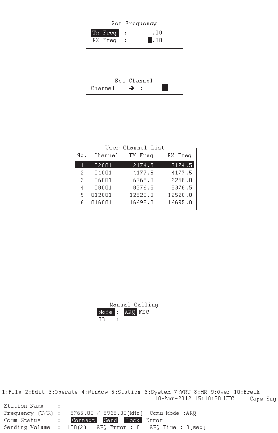
For IB-585:
• To enter the frequency, press the 9 key to select [Set Frequency]. Go to step 3.
• To enter the ITU or user channel, press the 0 key to select [Set Channel]. Go to
step 4.
3. Input a pair of TX and RX frequencies. Go to step 5.
4. Input the user channel. To select the user channel from the list, press the → key
to display [User Channel List]. Press the ↑ or ↓ key to select the desired user
channel.
5. Press the Enter key.
Note: You can not set frequency or user channel in the following cases;
• When opening the menu from the control panel (FS-2575C).
• When communicating by radiotelephone.
• When the DSC scan screen is displayed.
• When sending DSC calls.
6. Press the function key F3 then the 8 key to select [Manual Calling].
7. Press the ← or → key to select a communication mode.
8. Press the ↓ key then input party's ID number.
9. Press the Enter key to connect the communication line. "Channel Busy Check"
appears. If the line is free, "Connect", "Send" and "Lock" appear in highlight as be-
low.
10. NBDP TRANSMISSION, RECEPTION
10-3
For the ARQ mode, go to step 10. For the FEC mode, type your message then go
to step 13.
10. Press the function key F7. The party's answerback code appears on the screen.
Note: Step 10 and 11 are needed for ship-to-ship calling only.
11. Press the function key F8. Your ship's answerback code is sent to the party.
12. Press the Enter key and type your message.
13. If you want to receive other party's response, press the function key F9.
14. Press the function key F10 to disconnect the line.
10.2 ARQ Mode Operation
In ARQ operation, one station (information sending station) sends data to another
block by block, then listens for the acknowledge signal between blocks from the infor-
mation receiving station which requests either the next block or retransmission of the
last block if there is an error. The request can be repeated up to 32 times until the com-
plete block is received free of error.
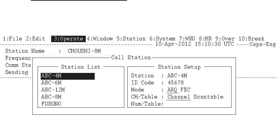
How to establish connection
1. Press the function key F3 to open the [Operate] menu.
2. Press the 1 key to select [Call Station].
3. Select a station. (Station must be registered for use in the ARQ mode).
4. Press the Enter key. The message "Calling Station" appears. If the message
shown below appears, check both the power of the radiotelephone and the con-
nections between the radiotelephone and the NBDP terminal unit.
Message: "Station calling suspended. Check interconnections between the termi-
nal and main units. Press any key to escape."
When an acknowledge signal is detected, "Connect" appears in reverse video on
the [Comm Status] line.
Note: If the signal conditions are poor, connection can take a while. If the line
could not be connected in one minute, the calling stops. The message "Station
calling suspended" appears. Try step 3 again, one minute later. Should the signal
conditions worsen during message transmission, "Error" appears in reverse video
on the [Comm Status] line and the line is disconnected.
5. Transmit message by one of the following methods:
Connect Send Lock
10. NBDP TRANSMISSION, RECEPTION
10-4
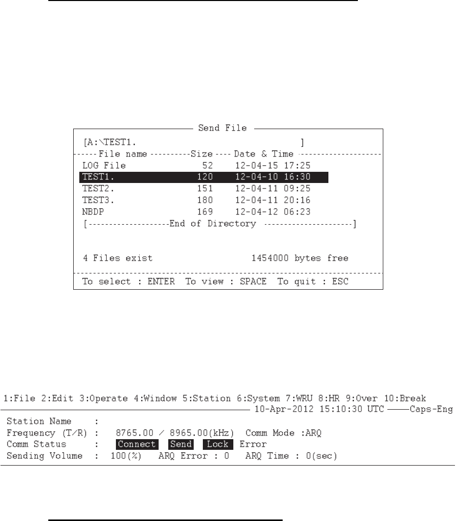
How to send a file stored on a floppy disk or an SD card
1. Press the function key F7 to request the answerback code of the other station.
Verify that the code from the station called is correct.
2. Press the function key F8 to transmit your own identity (answerback code).
3. Press the function key F3 then the 3 key to open the [Send File] window.
4. Press the ↑ or ↓ key to select the file to send and press the Enter key.
5. Press the Enter key again.
Sending volume (percentage of message transmitted, counts upward as the mes-
sage is being transmitted), ARQ error count and ARQ transmission time appear
on the screen. "Lock" appears in reverse video when the mark and space signals
in the received signal are normal. [ARQ Error] shows the number of errors found
during transmission. [ARQ Time] is the time in seconds the communication con-
nected.
6. After the message is transmitted, press the function key F10 to disconnect the
line.
How to type a message from the keyboard
1. After exchanging answerback code by the function keys F7 and F8, type your
message directly from the keyboard.
2. To change the direction of traffic, press the function key F9, or + and ? in order.
The other station becomes the information sending station, your station becomes
the information receiving station. Receive a message from the sending station.
3. After you have completed communications, press the function key F7 to request
the answerback code of the other station.
4. Press the function key F8 to transmit your own answerback code.
5. Press the function key F10 to disconnect the line.
Note: When you are requested to change the direction of traffic while transmitting a
message, or communication is interrupted because of an error, some of the final char-
acters on the screen may not be sent to the receiving station.

10. NBDP TRANSMISSION, RECEPTION
10-5
How to stop transmission
1. Press the function key F3 then the 4 key. The message "Send Canceled" appears
on the screen. Transmission is stopped but the line is still connected.
2. Press the function key F10 to disconnect the line.
10.3 FEC Mode Operation
The FEC mode transmits the same data twice for less errors. Compared with the ARQ
mode, the FEC mode is better for communication when the signal is weak.
1. Press the function key F3.
2. Press the 1 key to open the [Call Station] menu.
3. Press the ↑ or ↓ key to select a station which is registered for the FEC mode.
4. Press the Enter key. "Connect" appears in reverse video.
5. Transmit a message directly input from the keyboard, or do the following to trans-
mit a message stored on a floppy disk or an SD card:
1) Press the function key F3 then the 3 key to select [File to Send].
2) Press the ↑ or ↓ key to select the file to send then press the Enter key.
6. After the message is transmitted, press the function key F10 to disconnect the
line.
Note 1: When communication is force-quitted by control display, some of the final
characters may not be sent to the receiving station.
Note 2: When the continuous transmission by FEC mode exceeds one minutes, the
output power reduces to low automatically to prevent overheating.
10.4 How to Select Reception Mode
1. Press the function key F3 then the 6 key to open the [Manual Reception] menu.
2. Press the ← or → key to select the reception mode:
[AUTO]: Automatic reception in ARQ or FEC mode
[ARQ]: International radiotelex ARQ mode
[FEC]: International radiotelex FEC mode
3. Press the Enter key. The reception mode appears on the screen.
All received (and transmitted) mes-
sages are saved to a floppy disk or an
SD card when [TX/RX MSG Save] is
[ON] in the [System] menu. The file is automatically named (see the figure).
Note 1: Press the function key F10 to cancel NBDP reception (quit waiting for connec-
tion).
Note 2: For NBDP procedure controlled by DSC function, the function key F10 is not
available to cancel NBDP reception. Select [QUIT] option on the control panel to can-
cel NBDP reception.
Note 3: During reception in FEC mode, the characters which are not detected be-
cause of reception error are displayed as "*".
12 04 10 0 0. X X X
Year month date Serial number from 000
10. NBDP TRANSMISSION, RECEPTION
10-6
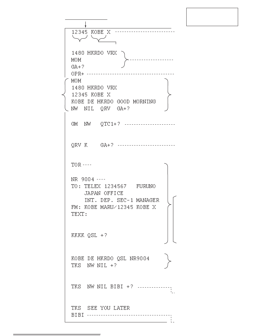
10.5 Communication Example
Call the coast station following the procedure in section 10.2. Then, communicate with
the coast station. Below is a communication example.
Communications example
If this is your first
communications with a
particular coast station,
the coast station asks
you selcall no., ship
name, call sign and
A
AIC (your enterprises
name for which to
charge toll call). That
registers you with the
coast station.
Thereafter, if your
answerback code is
correct, automatic
transmission is possible.
Coast station disconnects the line.
Own answerback code
Automatically sent from Coast
station (ex. Hong Kong)
Type at your side
(GM=Good Morning. I have a
message for you.)
Receiver: Telex no.1234567
FURUNO ELEC. CO.
Sender: KOBE MARU
Type message
Message completed. Can you
acknowledge receipt?
From coast station
From HKRDO to KOBE.
Received NR9004. Thank you.
No more to send.
Type at your side
(Thank you. I have nothing to
send. Bye Bye.
From coast station
(Thank you. See you later.)
From coast station
(Send your message.)
Type at your side
(To send a message
file, type MOM before
TOR and wait awhile.)
Type at your side within 30 s.
(Call operator manually.)
Message from coast station
(Wait. From HKRDO to KOBE.
Nothing to send. Do you have
anything to send?)
Call completed,
connected with
coast station To send message
to ship
Selcall No. Ship name or call sign
Teleprinting Over Radio
(Message TX starts.)
Msg No.
Type message.
End message.

10. NBDP TRANSMISSION, RECEPTION
10-7
Table of abbreviations
Command and abbreviation
Abbreviation Question Answer or Advice
QRA What is the name of your station? My station name is ...
QRC By what private enterprise are the ac-
counts for charges for your station set-
tled?
The accounts for my station are settled
by the private enterprise ...
QRU Have you any thing for me? I have nothing for you.
QRV Are you ready? I am ready.
QRX When will you call me again? I will call you again at ... hours [on ...
kHz].
QSJ What is the charge to be collected to ...
including your internal charge?
The charge to be collected to ... includ-
ing my internal charge is ...
QSL Can you acknowledge receipt? I can acknowledge receipt.
QSX Will you listen to ... [call sign] on ... kHz? I am listening to ... [call sign] on ... kHz.
QTA Shall I cancel message number ...? Cancel message number ...
QTC How many messages have you to send? I have ... message for you.
QTU What are the hours your station is open? My station is open from ... to ... hours.
Abbreviation Definition
BK Signal used to interrupt a transmission progress.
CFM Confirm
DE From ...
K Invitation to transmit.
NIL I have noting to send to you.
NW Now
PSE Please
R Received
REF Reference to ...
SVC Prefix indicating a service telegram.
Command Function
TGM+ To indicate that the following message is a radiotelegram.
MSG+ To indicate that the ship station needs to be connected immediately any message
held.
OPR+ Call operator.
URG+ Safety, urgency and distress message.
MED+ Request medical advice.
TEST+ Request coast station to send a test message for checking the ship station.
BRK+ To clear the connection with the coast station.
Abbreviation Function
GA+ I am ready. Transmit your command.
MOM Wait a moment.
MSG+ Request pending messages from the shore.
KKKK or NNNN Terminate a message.
XXXXX Typo
10. NBDP TRANSMISSION, RECEPTION
10-8
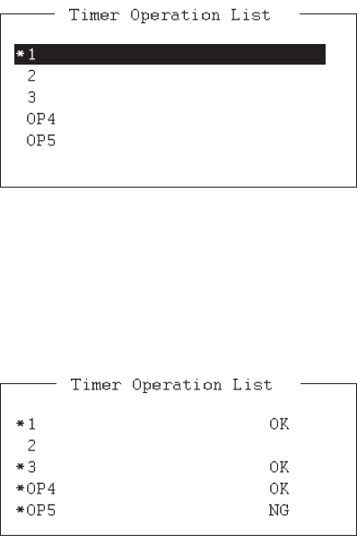
10.6 Timer Operation
A built-in timer permits automatic transmission and reception of telex messages.
10.6.1 How to enable timer operation
1. Press the function key F3 to open the [Operate] menu.
2. Press the 7 key to open the [Timer Operation List].
3. Press the ↑ or ↓ key to select the operation (name) to execute.
4. Press the Enter key. An asterisk appears beside the operation selected and "T.
Op" appears in reverse video on the communication status screen. If a file stored
on a floppy disk or an SD card is to be sent, be sure the floppy disk or the SD card
containing the file is inserted in the drive.
5. If desired, select another operation (name) then press the Enter key.
6. Press the Esc key.
When the predetermined time passed, the NBDP terminal unit automatically sends or
receives the message. The results of timer operation are displayed as either [OK] or
[NG] (No Good) on the [Timer Operation List] window.
10.6.2 How to stop timer operation
1. Press the function key F3.
2. Press the 7 key.
3. Press the ↑ or ↓ key to select the operation (name) which has an asterisk attached
to it then press the Enter key. Remove all asterisks to cancel all timer programs.
"T. Op" disappears from the communication status screen.
10. NBDP TRANSMISSION, RECEPTION
10-9
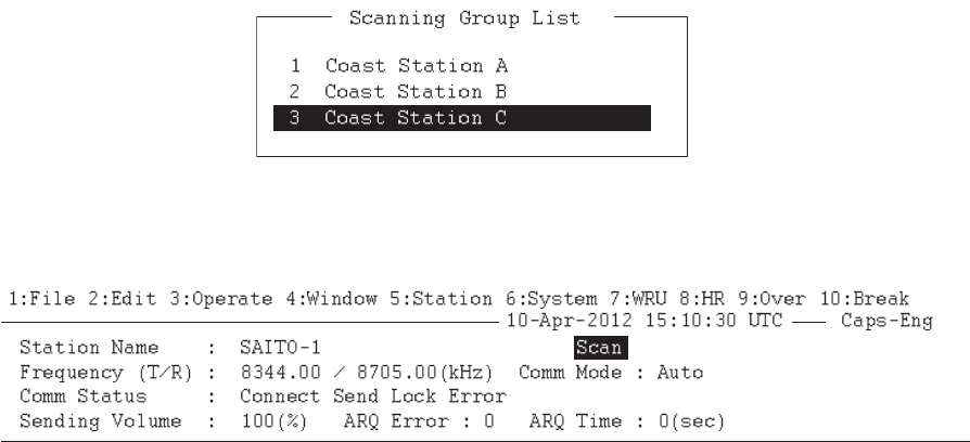
10.7 Scanning
The radio equipment scans a group of operator-selected frequencies (channels), and
stops scanning when a signal is received. See section 8.5 for registeration of scan
group.
1. Press the function key F3 then the 5 key to open [Scanning Group List]. You can
confirm the scan channel by pressing the ↑ or ↓ key while pressing the Shift key.
2. Press the ↑ or ↓ key to select a scan group then press the Enter key. The scan-
ning starts and the indication "Scan" appears in reverse video. Further, the name
of the scan group appears in the [Station Name] field.
Communication status screen
3. Press the function key F3 then the 5 key to stop scanning. "Scan" disappears from
the communication status screen.
10.8 Communication Buffer
The communication buffer is a temporary memory which stores the transmitted and
received messages. To display the contents of the communication buffer, do the fol-
lowing:
1. If necessary, close the [Edit] window 1 or 2, pop-up, or menu.
2. Press the Pg Up or Page Up, or Pg Dn or Page Down key. The contents of the
communication buffer are displayed.
Press the P key while pressing the Ctrl key to print them. Press the function key F1
then the 9 key to erase the contents of the buffer. To erase the contents from the
screen, do one of the following:
• Press the Pg Dn or Page Down key on the last page.
• Press the ↓ key at the bottom line.
• Press the Esc key.
*
10. NBDP TRANSMISSION, RECEPTION
10-10
10.9 Preparation of Macrofiles for Automatic Telex
10.9.1 Automatic telex overview
This section shows you how to communicate with a coast station which handles auto-
matic telex transmission, using macrofiles. You need to register communication chan-
nels and stations, and prepare macrofiles.
The coast stations using automatic telex are MCI Marine Services (North America),
Sydney Radio (Australia), Lyngby Radio (Denmark), and others. The procedure is
mostly common to all coast stations, however refer to the coast station's traffic manual
for details.
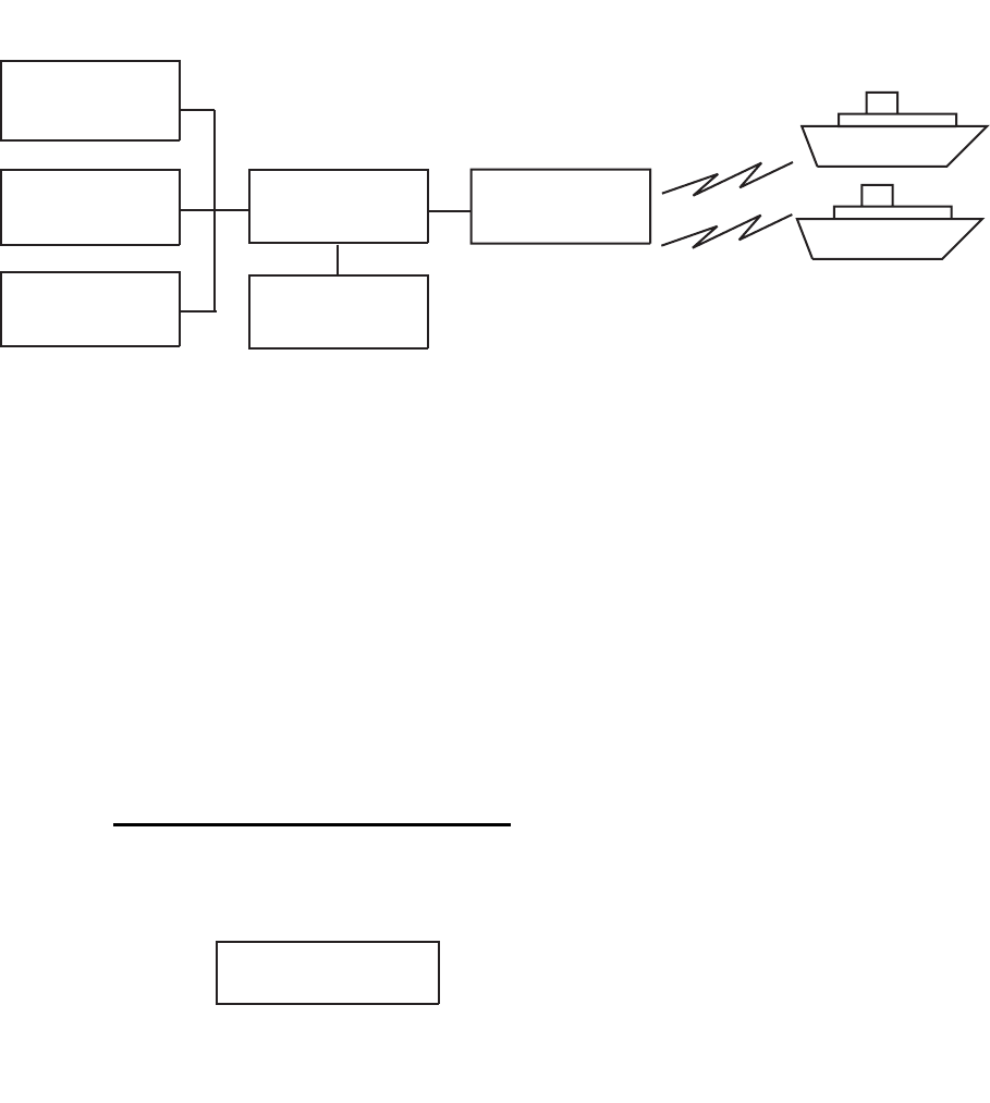
Sample of automatic telex network
The services available in automatic telex are
• Message transfer between ship and coast station (store-and-forward)
• Connection with landline telex (direct dialing)
• Multi address
10.9.2 Preparations
You need to register the following three items to use automatic telex.
How to register answerback code
The coast station assigns a telex number. This number functions as an answerback
code. An answerback code contains the following:
The procedure to register the answerback code is the same as which appears in
paragraph 8.1.1. If an answerback code was registered before the commissioning of
• Answerback code • Scan groups • Station names
INTERNATIONAL
TELEX NETWORK
STORE-AND-
FORWARD
DIRECT
DIALING
MULTI-
ADDRESS
CENTRAL
SYSTEM
SYSTEM
CONTROL
SUB-STATION
SHIP
OOOOO SHIP X
OOOOO: Coast station-assigned five-digit telex code
SHIP: Ship name
X: For shipboard station, normally X is entered

10. NBDP TRANSMISSION, RECEPTION
10-11
the coast station, a new answerback code must be entered. Contact FURUNO or an
authorized FURUNO agent or dealer to enter a new answerback code.
How to register scan groups
The central system emits a free-signal to indicate a coast station radio channel is in
idle condition and available for ship-to-shore calls. The free-signal is detected and rec-
ognized by the shipboard equipment as a permission to start the transmission. Then,
the shipboard operator initiates a call.
You can automatically scan search for the free-signal by registering coast station radio
channels in scan group(s). The procedure to register scan groups for coast station use
is the same as that which appears in paragraph 8.5.1.
How to register stations
The next step is to enter station name. The procedure is the same as that shown in
paragraph 8.3.1.
10.9.3 Commands
The following tables describe the commands for macro operation.
Command
(Prefixed with @) Parameter Content
CALL S: Station Name Calling station name and ID on
assigned parameter
FREE (support command
for CALL)
Two digits, 0-99 min Free-channel signal searching
time according to assigned pa-
rameter (default setting: 10 min)
$R$ Detect free-channel signal of
200 ms dot pattern
$RR$ Detect free-channel signal of
300 ms dot pattern
$RRR$ Detect free-channel signal of
400 ms dot pattern
$RRRR$ Detect free-channel signal of
500 ms dot pattern
$RRRRR$ Detect free-channel signal of
600 ms dot pattern
$RRRRRR$ Detect free-channel signal of
700 ms dot pattern
$RRRRRRR$ Detect free-channel signal of
800 ms dot pattern
$RRRRRRRR$ Detect free-channel signal of
900 ms dot pattern
The combination of two
capital letters and "c".
For example: $EcR$
Detect free-channel signal like
ARQ call block E, RQ, R "c" for
repetition signal RQ.

10. NBDP TRANSMISSION, RECEPTION
10-12
Example: Commands
For details, see the coast station's traffic manual.
RETRY (support com-
mand for CALL)
Two digits, 0-99 min Calling according to assigned
parameter (default setting: 10
min)
CASE Text For receiving a message (des-
ignated by parameter) transmit-
ted by coast station
TIMEOUT (support com-
mand for CALL)
Two digits, 0-99 min Time allotted for reception of
message by CASE command
SEND Text Text transmitted according to
assigned parameters
A: file name Send a file from floppy disk
WRU
HR
OVER
BREAK
None Function keys F7 - F10
DISPLAY Text Text of message appears
INPUT None Waiting for keyboard input.
Transmit keyboard input mes-
sage.
Command Function
BRK+ Disconnect communications line
DIRTLX ...... + Direct dialing telex (receive only)
KKKK Terminate message
LTR+ For telex letters mailed from Operations Station to destinations
worldwide
MED+ Request medical advice
OPR+ Request operating assistance
POS+ Send position data
STA+ Status requested on a store-and-forward message
TLX ...... + Store-and-forward method
Command
(Prefixed with @) Parameter Content
10. NBDP TRANSMISSION, RECEPTION
10-13
10.9.4 Store-and-forward method
The following is the sequence of events for transmission of a file by the store-and-for-
ward method.
1. Ship station sends message to coast station.
2. Coast station stores message in memory buffer.
3. Ship station and coast station clear the radio circuit.
4. Coast station sends message to subscriber designated.
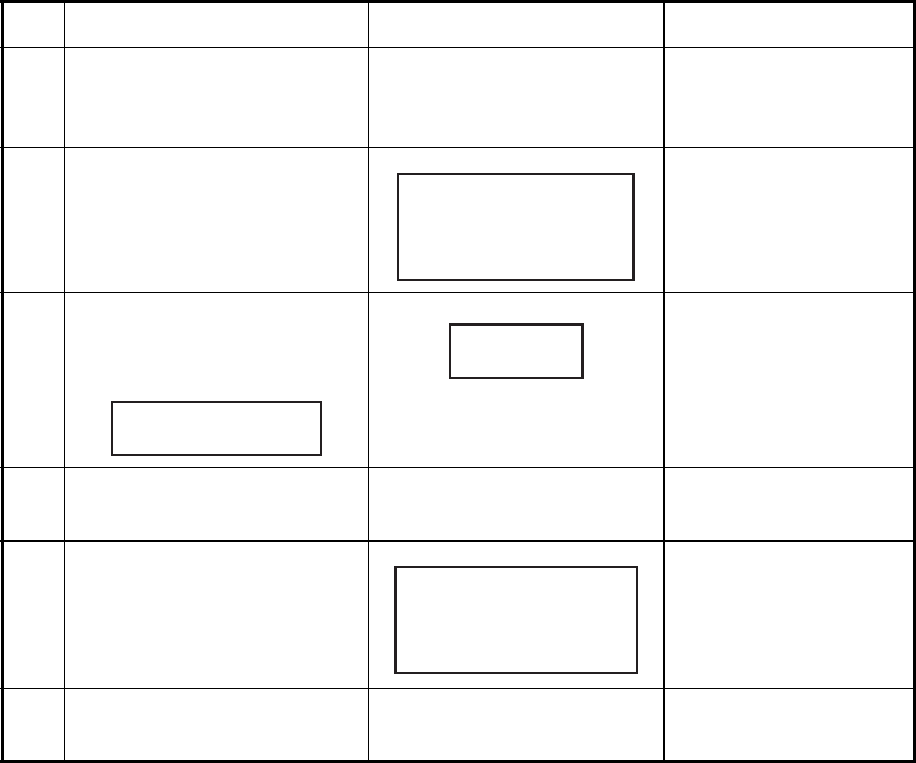
Actual procedure for store-and-forward telex
Procedure to prepare a macrofile for store-and-forward method
You need a macrofile to enable automatic message transmission by store-and-for-
ward method. After preparing it, save it to a floppy disk for future use.
1. Press the function key F1 to open the [File] menu.
2. For IB-585, press the B key. For IB-583, press the 1 key.
No. Procedure Display Remarks
1 Call a coast station. "Connect" appears in re-
verse video and bell
sounds.
Free-signal found; ra-
dio circuit ready.
2 Transmit WRU signal. Initial identity ex-
change between
coast station and ship-
board station.
3 Key in subscriber's telex
number. Example: (Hong
Kong) 12345
Request to start mes-
sage transmission.
4 Transmit file. Message transmis-
sion.
5 When transmission is com-
pleted, type KKKK.
Transmit your answer-
back code. Receive
other party's answer-
back code.
6 Transmit BREAK command
to clear radio circuit.
00190 TLG DK
26XXX SHIP X
GA+?
TLX80212345+
MSG+?
26XXX SHIP X
00190 TLG DK
GA+?
10. NBDP TRANSMISSION, RECEPTION
10-14
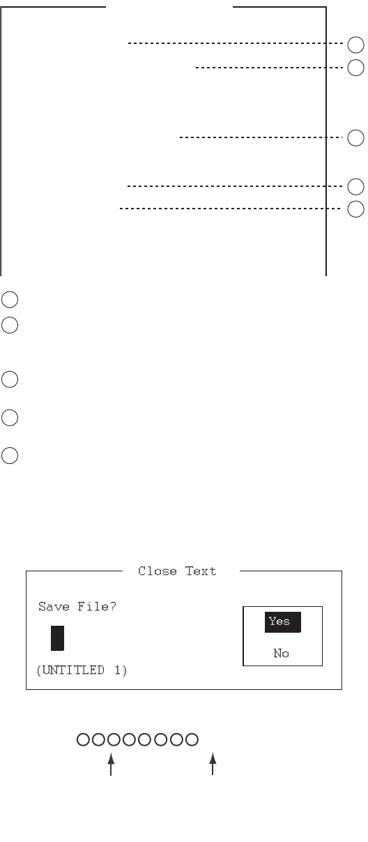
3. Prepare the macrofile. Below is a simple example.
Sample macrofile for store-and-forward method
4. Press the function key F1 to open the [File] menu.
5. Press the 3 key. The [Close Text] appears.
6. Press the Enter key then enter a file name as follows:
7. Press the Enter key.
< [1] UNTITLED1 >
@FREE $RRR$
@CALL S:LYNGBY RADIO
@WRU
@CASE GA+?
@SEND TLX80212345+
@CASE MSG+?
@SEND
A: \ABC
@SEND KKKK
@CASE GA+?
@SEND BRK+
Search dot pattern free signal until it is found
1
2
3
4
5
Station name (Example: LYNGBY RADIO)
Who are you?
Station identity exchange
Subscriber's telex number (in example, 802 is country
code of Hong Kong) for store-and-forward method
Location and name of file message
A: \ABC
Request for termination of message
1
2
3
4
5
.MCR
File name (max.
14 characters in
conjunction with
identifier)
Extension name
10. NBDP TRANSMISSION, RECEPTION
10-15
DIRTLX macrofile
Sample DIRTLX macrofile
Sample DIRLTX macrofile
10.10 Automatic Telex Using Macrofile
This section describes how to transmit a telex message using a macrofile.
Basic procedure
1. Register an answerback code (telex number assigned by the coast station).
2. Register the coast station frequency and channel to a scan group.
3. Register the station name including the scan group name.
4. Retrieve a macrofile. Include the station name and the message file name. Type
the message and save the file.
5. Open the macro operation menu and select a macrofile. Your message will be
transmitted automatically. Below is the sequence of automatic message transmis-
sion to a coast station.
1) Search for free-signal
2) Call coast station on one of its radio channels
3) After connection is established, identity exchange
4) Transmission of service category and subscriber's address
5) Transmission of message
< [1] UNTITLED1 >
@FREE $RRR$
@CALL S:LYNGBY RADIO
@WRU
@CASE GA+?
@SEND DIRTLX725644325+
@CASE MSG+?
@SEND
A: \ABC
@SEND KKKK
@CASE GA+?
@SEND BRK+
Search dot pattern free signal until it is found
1
2
3
4
5
Station name (Example: LYNGBY RADIO)
Who are you?
Station identity exchange
Subscriber's telex number (in example, 72 is country
code of Japan) for direct dialing mode
Location and name of file message
A: \ABC
Request for termination of message
1
2
3
4
5
10. NBDP TRANSMISSION, RECEPTION
10-16
6) Transmission of termination of message signal
7) Identity exchange
8) Clearing of radio circuit
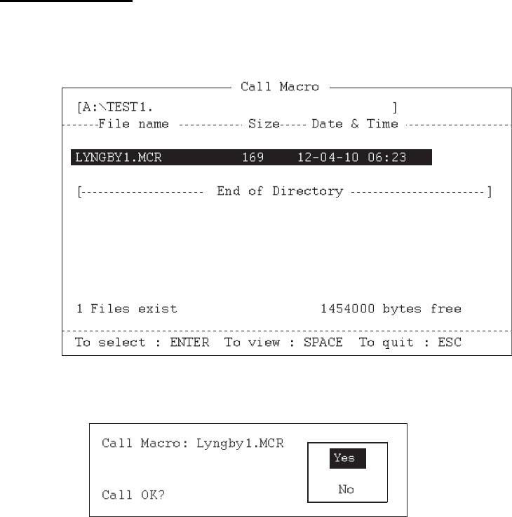
Actual procedure
1. Press the function key F3 to open the [Operate] menu.
2. Press the 2 key to open the [Call Macro] window.
3. Press the ↓ key to select a macrofile.
4. Press the Enter key.
5. Press the Enter key to confirm the macrofile selected. The message "Wait for
Free Signal" appears. Your message is transmitted automatically.
11-1
11. MAINTENANCE &
TROUBLESHOOTING
11.1 Test
Do the following tests to check the radiotelephone for proper operation.
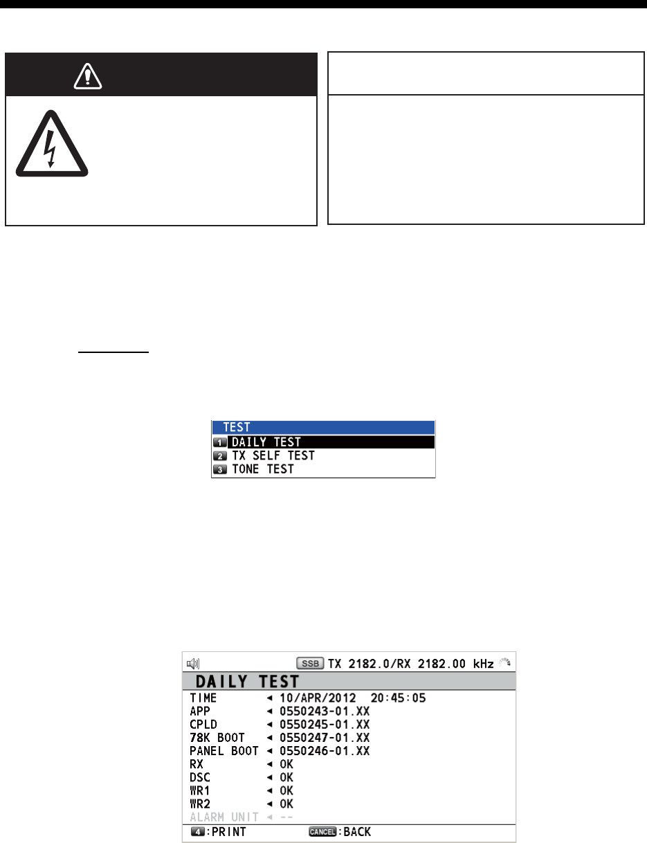
Daily test
1. Rotate the ENTER knob to select [TEST] on the [MENU] screen then push the
knob.
2. With [DAILY TEST] selected, push the ENTER knob to start the test. After com-
pleting the test, the audio alarm sounds and the screen shown below appears.
This screen shows:
• Program version numbers.
• Test results for RX, DSC, WR1 and WR2, shown as [OK] or [NG] (No Good).
For NG, contact your dealer for advice. The DSC test checks, using a DSC sig-
nal, the encode and decode functions of the signal processor.
To print out the test result manually, press the 4 key. Automatic printing of the daily
test is available. See section 6.6.
WARNING
WARNING
NOTICE
Do not apply paint, anti-corrosive sealant
or contact spray to plastic parts or
equipment coating.
Those items contain products that can
damage plastic parts and equipment coating.
ELECTRICAL SHOCK HAZARD
Do not open the equipment.
Only qualified personnel
should work inside the
equipment.
11. MAINTENANCE & TROUBLESHOOTING
11-2
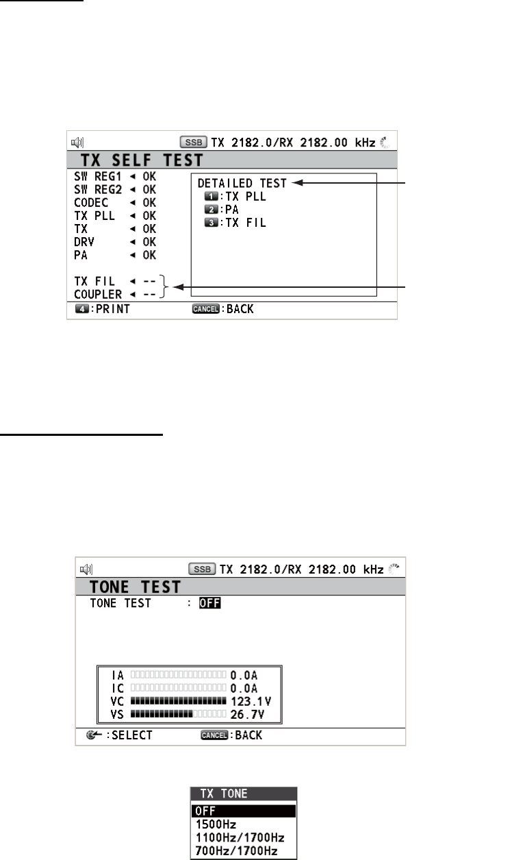
TX self test
1. Rotate the ENTER knob to select [TEST] on the [MENU] screen then push the
knob.
2. Rotate the ENTER knob to select [TX SELF TEST] then push the knob. [OK] or
[NG] (No Good) appears as the test result for each item. For [NG], contact your
dealer for advice.
[SW REG1], [SW REG2]: For FS-2575/5075
[DRV]: For FS-2575/5075
[PA2], [COMB] ([DETAILED TEST] for [PA]): For FS-5075
Others: For FS-1575/2575/5075
Tone test (SSB mode)
You can execute tone test with lowering transmission power.
1. Rotate the ENTER knob to select [TEST] on the [MENU] screen then push the
knob.
2. Rotate the ENTER knob to select [TONE TEST] then push the knob.
3. With [OFF] selected, push the ENTER knob.
4. Rotate the ENTER knob to select the item desired then push the knob. Press the
PTT switch of the handset to output the tone signal from the speaker.
Unexecuted items
Press the 1, 2 or
3 key to see the
detailed test result
for [TX PLL], [PA]
or [TX FIL].

11. MAINTENANCE & TROUBLESHOOTING
11-3
11.2 Maintenance
Regular maintenance helps to keep your equipment in good condition and prevents
future problems. Check the items shown in the table below.
Item Check point Remedy/Remarks
Antenna Check for physical damage and corro-
sion.
Replace damaged parts.
Wire antenna Check that the antenna is properly
spanned and separated sufficiently
from metallic structures.
If necessary, re-span antenna.
Insulators for
antenna
Check for salt water deposits on insula-
tors. Check that connection at the lead-
in insulator is tight and rust-free.
Replace damaged insulator(s). Re-
move salt water deposits. Clean with
fresh water, then dry. Remove rust,
then tighten bolts and lock nuts. Cover
metallic surface with sealing compound.
Antenna cou-
pler
• Check condition of antenna terminal,
ground, coaxial cable and control ca-
ble.
• Check that coupler lid and cable
glands are firmly secured.
• Check for physical damage, corro-
sion and salt water deposits.
• Tighten the loosened connections.
• Fasten the lid firmly and evenly to
prevent water leakage.
• Replace if damaged.
Control unit • Check ground connection, control ca-
ble, and external equipment.
• Confirm that there are no objects on
the top of the control unit.
• Remove dust from control unit with
soft cloth.
Note: Do not use chemical cleaners to
clean the control unit; they can remove
paint or markings and deform the equip-
ment.
• Tighten the loosened connections;
remove foreign materials from con-
nectors.
• Remove any objects.
• Wipe the LCD carefully to prevent
scratching, using tissue paper and an
LCD cleaner. To remove dirt or salt
deposits, use an LCD cleaner, wiping
slowly with tissue paper so as to dis-
solve the dirt or salt. Change paper
frequently so the salt or dirt does not
scratch the LCD.
Transceiver
unit
• Check connection at signal cable, co-
axial cable, control cable, power ca-
ble, and navigator.
• Confirm that there are no objects on
the top of the cabinet.
• Tighten loosened connections; re-
move foreign materials from connec-
tors.
• Remove any objects.
Power supply Check that the supply voltage at trans-
mission is within the rated range (21.6
to 31.2 VDC at the power connector).
If not within the range, check power
source. Low voltage may cause erratic
operation.

11. MAINTENANCE & TROUBLESHOOTING
11-4
11.3 Simple Troubleshooting
The table below provides possible problems and the means with which to restore nor-
mal operation. If normal operation cannot be restored, do not attempt to check inside
the equipment. Any servicing should be referred to a qualified technician.
11.4 Error Messages
The table below shows error messages, their meanings, and remedies. To delete the
messages, press the CANCEL key. If other error occurs, contact your dealer.
Problem Probable cause Remedy
Power cannot be
turned on.
• Mains switchboard is off.
• (DC) voltage is too high.
• Battery has discharged, or poor
contact at terminals.
• Turn on the mains switchboard.
• Check supply voltage.
• Recharge the battery and tighten
the battery terminals.
Display indications do
not appear.
Display brilliance is too low. Press the BRILL key to adjust the
display brilliance.
Power is on but no
sound from the main
speaker.
Main speaker is off. Press the key to turn on the main
speaker.
Poor articulation Wrong class of emission. Class of emission should match that
of incoming signal.
Output power re-
duced to LOW
Power is automatically reduced to
protect against overheating due to
continuous transmission.
Wait until the unit cools.
Antenna coupler can-
not tune antenna
• Antenna is disconnected or short-
ed to ground.
• Antenna is out of tunable length.
• Poor grounding of antenna cou-
pler.
• Breaker in coupler has tripped.
• Connection cable loosened or dis-
connected.
• Check the antenna connection.
• Recommended length is 10 to 18
meters.
• Check coupler ground.
• Check mains voltage and polarity.
If normal, reset the breaker.
• Check the cable.
Error message Meaning Remedy
ERROR:
TX PLL UNLOCK
[CANCEL]: Stop alarm
TX PLL is unlocked. Transmission is
stopped.
Contact your dealer.
ERROR:
RX PLL UNLOCK
[CANCEL]: Stop alarm
RX PLL is unlocked. Reception is
stopped.
Contact your dealer.
ERROR:
WR1(2) PLL UNLOCK
[CANCEL]: Stop alarm
WR1(2) PLL is unlocked. Reception
is stopped.
Contact your dealer.
ERROR:
Tx power reduced.
Main AMP heated.
[CANCEL]: Stop alarm
Power amplifier is too hot. Trans-
mission power is reduced to one
level lower.
Allow amplifier to cool.
ERROR:
Tx power reduced.
Ship's main failure.
[CANCEL]: Stop alarm
AC power is interrupted and re-
placed with DC power (only when
connecting PR-850A).
Can use DC power with low trans-
mission power. Check AC power
and decrease the transmission
power to the minimum.
System was rebooted. Unusual event is detected. System restarts automatically.

11. MAINTENANCE & TROUBLESHOOTING
11-5
11.5 Breaker on PR-850A
The AC-DC power supply unit PR-850A has a circuit breaker. If the breaker has
tripped, find the reason before resetting the breaker.
11.6 Test Call
This function sends a test signal to a coast or ship station, over one of six distress and
safety frequencies. For that reason, it should not be executed unnecessarily. You can
prepare a test call beforehand (see paragraph 6.16.5).
1. Press the OTHER DSC MSG key to open the [COMPOSE MESSAGE].
2. Rotate the ENTER knob to select [MSG TYPE] then push the knob.
3. Rotate the ENTER knob to select [TEST MSG] then push the knob. [PRIORITY]
is automatically set to [SAFETY].
4. With [TO] selected, push the ENTER knob.
5. Rotate the ENTER knob to select [DIRECT INPUT] or [ADDRESS BOOK DATA]
then push the knob.
[ADDRESS BOOK DATA]: Select a MMSI from the [ADDRESS BOOK] (see
section 6.15) then push the ENTER knob.
[DIRECT INPUT]: Enter the MMSI of the station where to send the test message
then push the ENTER knob.
6. With [DSC FREQ] selected, push the ENTER knob.
7. Rotate the ENTER knob to select DSC frequency then push the knob.
8. With [GO TO CALL] selected, push the ENTER knob to send the test message.
The screen is changed to one for transmission. After the call is sent, the equip-
ment waits for acknowledgement of the call. The timer starts counting up the time
to wait for acknowledgement.
9. Do one of the following.
Test acknowledge message received
The audio alarm sounds and the message "TEST ACK received! [CANCEL]: Stop
alarm" appears. Press the CANCEL key to silence the alarm.
ERROR:
VC error!
Please restart
the power supply.
[CANCEL]: Stop alarm
VC voltage decreases. Transmis-
sion is stopped.
Reset the power. If normal opera-
tion is not restored, contact your
dealer.
Error message Meaning Remedy
POWER
ON
ON
OFF
AC INPUT 50/60Hz DC OUTPUT
Breaker

11. MAINTENANCE & TROUBLESHOOTING
11-6
No response
Re-send call: Rotate the ENTER knob to select [RESEND] in the user options area
then push the knob.
Cancel call: Rotate the ENTER knob to select [QUIT] in the user options area then
push the knob.
11.7 NBDP Terminal Unit Maintenance
Regular maintenance is important for good performance. A regular maintenance pro-
gram should be established and should at least include the items mentioned below.
11.7.1 Cleaning the equipment
Wipe the LCD carefully to prevent scratching, using tissue paper and an LCD cleaner.
To remove dirt or salt deposits, use an LCD cleaner, wiping slowly with tissue paper
so as to dissolve the dirt or salt. Change paper frequently so the salt or dirt does not
scratch the LCD. Do not use solvents such as thinner, acetone or benzene for clean-
ing. Also, do not use degreaser or antifog solution, as they can strip the coating from
the LCD.
11.7.2 Connectors and earth connection
Periodically check the connectors for proper seating and the earth connection for rust.
Remove rust to maintain a good ground system.
11.7.3 Floppy disk drive
Foreign materials on the floppy disk drive head can scratch the magnetic materials on
the floppy, resulting in loss of data. Clean the floppy disk drive head regularly with a
floppy disk drive cleaning disk to prevent erasure of information stored on disks.
11.7.4 Diagnostics
General diagnostics
1. Press the function key F6 to open the [System] menu.
Setup
Slave Delay
TX/RX MSG Save
Edit Before sending
TX POWER*
Header/Footer*
Time System
Time & Date
Window Color
Self Test
Lock Change Default
xx msec (10 - 50 msec)
OFF ON
OFF ON
HIGH MID LOW
OFF ON
OFF UTC SMT JST
10/Apr/2012 10:00:00
System
For serviceman
No need to change.
Only serviceman
can change.
*: Only for IB-585
11. MAINTENANCE & TROUBLESHOOTING
11-7
2. Select [Change] at [Setup].
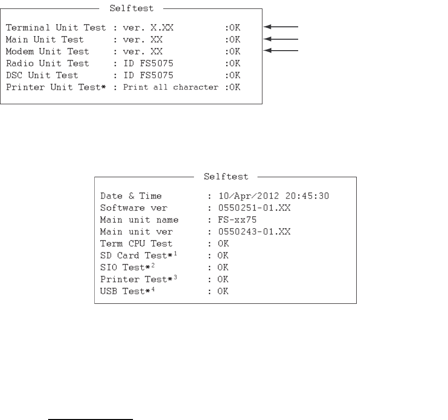
3. Select [Self Test] at the bottom of the screen.
4. Press the Enter key. The results of the self test are displayed a short time later.
Selftest results for IB-583
Selftest results for IB-585
Self test results
The test results are shown as [OK] or [NG] (No Good). For any [NG], check the con-
nection of the equipments then try the self test again. If it appears again, call for ser-
vice. When the test is completed, the message "Selftest Completed. Press any key to
escape." appears.
X.XX: Version No.
*: "NG" and "Printer not ready" when printer is off or abnormal.
IB-583
Main terminal soft (T-CPU board)
NBDP modem
XX: Version No.
xx: FS-1575, FS-2575 or FS-5075
*1: “NG” when the SD card is not inserted.
*2: “NG” when FS-xx75 is turned off.
*3: "NG" and "Printer not ready" when printer is off or abnormal.
*4: The message “Press 3 keys” appears. Press any three keys.
11. MAINTENANCE & TROUBLESHOOTING
11-8
This page is intentionally left blank.
AP-1
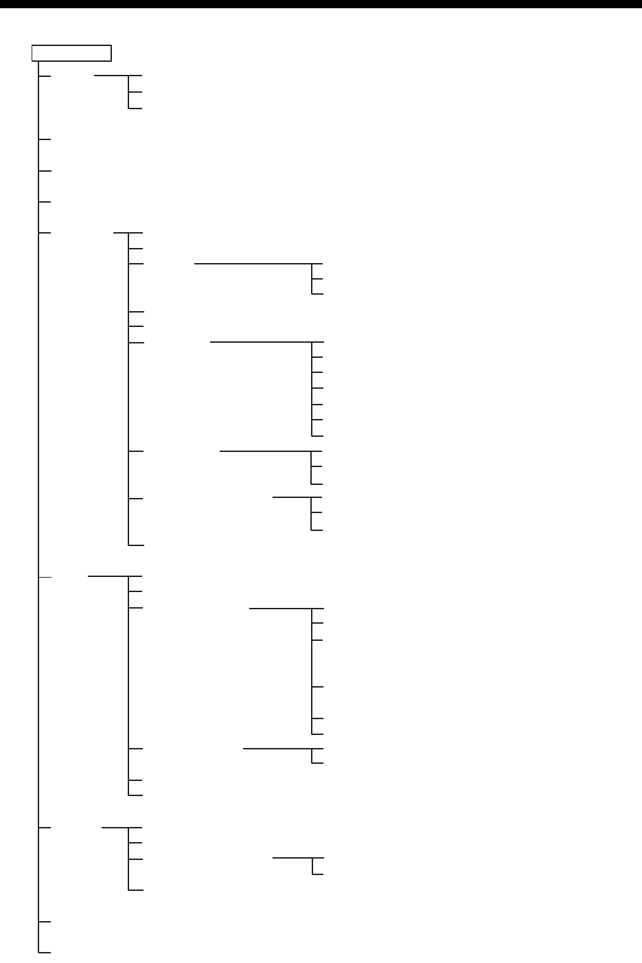
APPENDIX 1 MENU TREE
MENU key Bold: Default setting
TEST
USER CH
(open user channel list)
LOG (open log data list)
INTERCOM
SYSTEM
DSC
AUDIO
ALARM (open alarm list)
SERVICE (For serviceman)
DAILY TEST
TX SELF TEST
TONE TEST
SQ FREQ (500Hz - 2000Hz, 1000Hz)
KEY ASSIGN (F1 (RX FREQ), F2 (DAILY TEST), F3 (TEST CALL))
PRINT
POSITION (open setting window)
DATE/TIME (open setting window)
TIMEOUT
RX SETUP
EXTERNAL ALARM
NETWORK
ADDRESSBOOK (open address data list)
MSG FILE (open message file list)
ACK SETTINGS
SPECIAL MSG
ROUTINE SCAN
DISTRESS SCAN
KEY CLICK (0 - 3, 2)
OFF HOOK SP (SP ON, MUTE)
ORDINARY ALARM
ALARM DISTANCE (500NM, OFF)
TX MSG (AUTO, MANUAL)
RX MSG (AUTO, MANUAL)
DAILY TEST (AUTO, MANUAL)
MENU END (10MIN, NO TIMEOUT)
DSC GENERAL (15MIN, NO TIMEOUT)
RX DISTRESS (15MIN, NO TIMEOUT)
SSB (10SEC, 30SEC, 10MIN)
TELEX (10SEC, 30SEC, 10MIN, NO TIMEOUT)
FAX (10SEC, 30SEC, 10MIN, NO TIMEOUT)
AM (10SEC, 30SEC, 10MIN, NO TIMEOUT)
FAX RX (ENABLE, DISABLE)
ANT SELECT (TRX ANT, RX ANT)
CLARIFIER (ON, OFF)
URGENCY (ON, OFF)
SAFETY (ON, OFF)
ROUTINE (ON, OFF)
SAFETY (0 - 5, 5)
ROUTINE (0 - 5, 5)
INDIVIDUAL (MANUAL, AUTO (UNABLE))
PSTN (AUTO (ABLE), AUTO (UNABLE))
REASON (NO REASON, BUSY,
EQUIP ERROR, CAN'T USE MODE,
CAN'T USE CH)
POSITION MSG (AUTO (ABLE),
AUTO (UNABLE), MANUAL)
POLLING MSG (AUTO, MANUAL)
TEST MSG (AUTO, MANUAL)
NEUTRAL (ABLE, UNABLE)
MEDICAL (ABLE, UNABLE)
APPENDIX 1 MENU TREE
AP-2
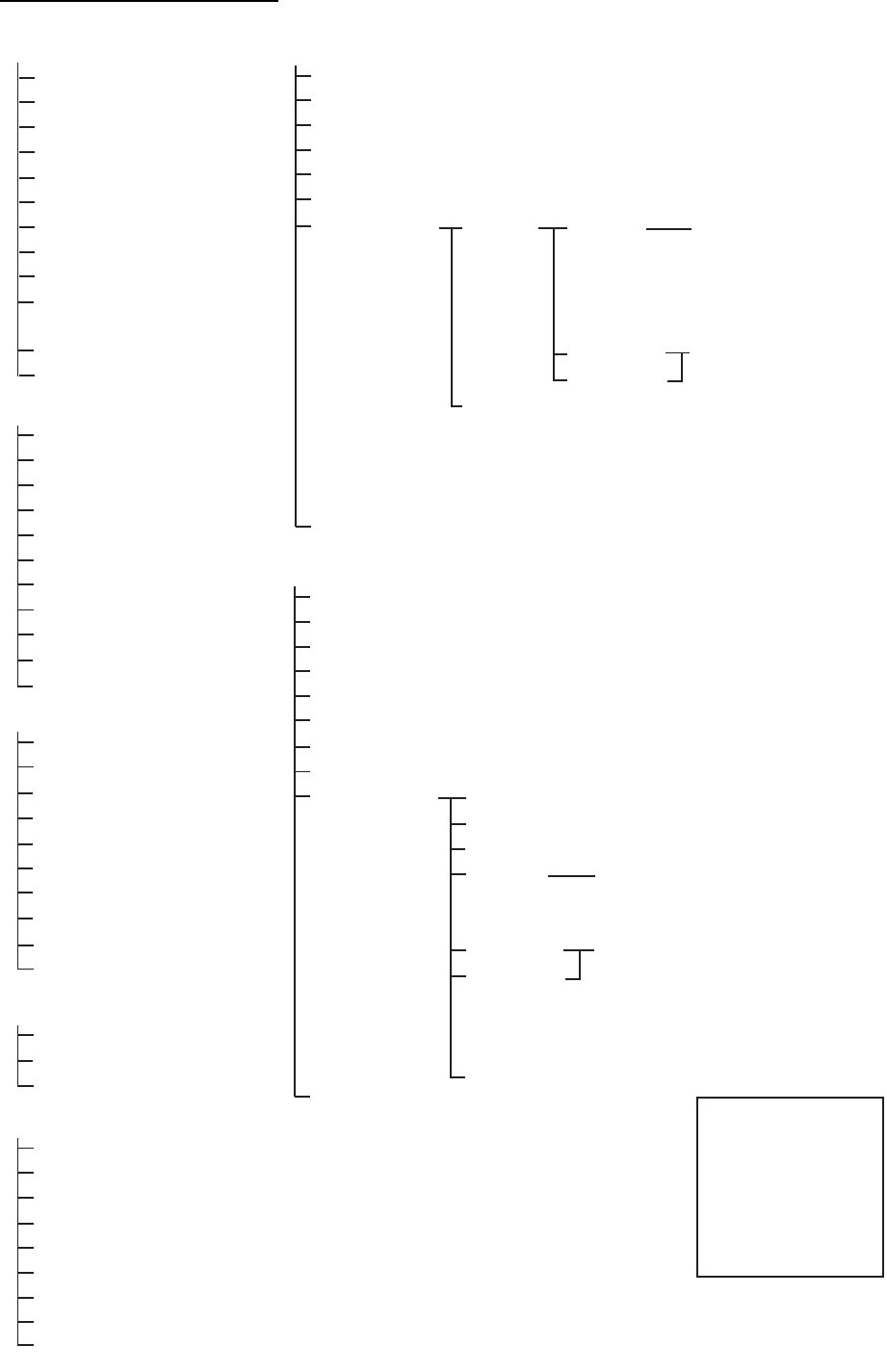
NBDP terminal unit (telex)
Bold: Default setting
F1: File
F2: Edit
F3: Operate
F4: Window
1: New
2: Open
3: Close
4: Delete
5: Rename
6: Real Time Printing
7: File to Print
8: Cancel Priniting
9: Clear Buffer
0: Floppy Disk Format*1 or
SD Card Format*2
A: Remove SD Card*2
B: New Macro*2
1: Undo
2: Cut
3: Copy
4: Paste
5: Select All
6: Search
7: Replace
8: Goto Top
9: Goto Bottom
0: Goto Line
A: Change Text
1: Call Station
2: Macro Operation
3: File to Send
4: Cancel Sending
5: Scan (Start/Stop)
6: Manual Reception
7: Timer Operation
8: Manual Calling
9: Set Frequency
0: Set Channel*2
1: Calendar
2: Distress Frequency Table
3: Screen Saver*2 (OFF, ON)
F7: WRU (Who are you?)
F8: HR (Here is)
F9: Over
F5: Station
F6: System*1
1: Station Entry
2: Timer Operation (Entry)
3: Scan Entry
4: User Channel Entry*1
5*3: Answerback Code Entry
6*3: Group ID Entry (4/5 digit)
7*3: Group ID Entry (9 digit)
8*3: Select ID Entry (4/5 digit)
9*3: Select ID Entry (9 digit)
Setup (Lock, Change, Default)
Slave Delay (0-50 msec, 8)
TX/RX MSG Save (OFF, ON)
Edit Before Sending (OFF, ON)
Time System (OFF, UTC, SMT, JST)
Time & Date
Window Color
Self Test
Window
Color
Setup
Default Color
Window
Fore Color
Back Color
BASE WINDOW,
BACK SCROLL,
EDIT 1-2, FUNCTION,
SUB MENU 1-3,
MESSAGE
L-WHITE, YELLOW,
L-MAGENTA, L-RED,
L-CYAN, L-GREEN,
L-BLUE, GRAY,
WHITE, BROWN,
MAGENTA, RED,
CYAN, GREEN,
BLUE, BLACK
*1: For IB-583
*2: For IB-585
*3: For IB-585, the
numbers after 5
are moved up.
*4: For FS-1575/2575
*5: For FS-5075
F6: System*2
Setup (Lock, Change, Default)
Slave Delay (10-50 msec, 12)
TX/RX MSG Save (OFF, ON)
Edit Before Sending (OFF, ON)
TX Power (HIGH, MID, LOW*4, (LOW1, LOW2)*5)
Header/Footer (OFF, ON)
Time System (OFF, UTC, SMT, JST)
Time & Date
Window Color
Self Test
Window Color Edit
Target Present (1, 2, 3)
Load Default
Window
Fore Color
Back Color
Brightness (0 - 10, 10)
BASE WINDOW, BACK SCROLL,
EDIT 1-2, FUNCTION,
SUB MENU 1-3, MESSAGE
WHITE, BLACK, L-WHITE, GRAY,
L-BLUE, BLUE, L-GREEN,
GREEN, L-CYAN, CYAN,
L-RED, RED, L-MAGENTA,
MAGENTA, L-YELLOW, YELLOW
F10: Break
F11: Setup*2 (For serviceman)

AP-3
APPENDIX 2 FREQUENCY TABLES
DSC frequency table
*: Ship-to-ship
TX (kHz) RX (kHz) Remarks File Name
2187.5 2187.5 Distress and Safety
Frequencies
4207.5 4207.5
6312.0 6312.0
8414.5 8414.5
12577.0 12577.0
16804.5 16804.5
2189.5 (2177.0*) 2177.0 International Frequen-
cies
INTL-2M
4208.0 4219.5 INTL-4M
6312.5 6331.0 INTL-6M
8415.0 8436.5 INTL-8M
12577.5 12657.0 INTL-12M
16805.0 16903.0 INTL-16M
18898.5 19703.5 INTL-18M
22374.5 22444.0 INTL-22M
25208.5 26121.0 INTL-25M
4208.5 4220.0 Local-1 Frequencies LOCAL1-4M
6313.0 6331.5 LOCAL1-6M
8415.5 8437.0 LOCAL1-8M
12578.0 12657.5 LOCAL1-12M
16805.5 16903.5 LOCAL1-16M
18899.0 19704.0 LOCAL1-18M
22375.0 22444.5 LOCAL1-22M
25209.0 26121.5 LOCAL1-25M
4209.0 4220.5 Local-2 Frequencies LOCAL2-4M
6313.5 6332.0 LOCAL2-6M
8416.0 8437.5 LOCAL2-8M
12578.5 12658.0 LOCAL2-12M
16806.0 16904.0 LOCAL2-16M
18899.5 19704.5 LOCAL2-18M
22375.5 22445.0 LOCAL2-22M
25209.5 26122.0 LOCAL2-25M

APPENDIX 2 FREQUENCY TABLES
AP-4
Custom channels (to be programmed by FURUNO dealers)
CH NO Ship Receive (kHz) Ship Transmit (kHz) Remarks

APPENDIX 2 FREQUENCY TABLES
AP-5
MF band working carrier frequencies (ref. US CFR 47 Part 80.371)
Above frequencies are not programmed. Contact a FURUNO representative.
1 = Unlimited use December 15 to April 1
2 = 2206 kHz for distress only
3 = Limited to pep of 150 W
Region Ship Transmit
(kHz)
Ship Receive
(kHz)
East Coast
West Coast
2031.5
2118.0
2126.0
2142.0
2166.0
2198.0
2366.0
2382.0
2390.0
2400.0
2406.0
2490.0
2514.01
2522.0
2538.0
2558.0
2590.0
2450.0
2482.0
2566.0
2400.0
2506.0
2003.0
2009.0
2009.0
2031.5
2126.0
2206.0
2382.0
2406.0
2430.0
2450.0
2442.0
2566.0
2566.0
2522.0
2598.0
2466.0
2506.0
2482.0
Region Ship Transmit
(kHz)
Ship Receive
(kHz)
Gulf Coast 2009.0
2134.0
2142.0
2158.01
2166.0
2206.0
2366.0
2382.0
2430.0
2458.0
2466.0
2530.0
2538.0
2550.01
2558.0
2598.0
2450.0
2482.0
2572.0
2506.0
Great Lakes22118.0
2158.0
2206.0
2514.0
2550.0
2582.0
Alaska 2131.0
2134.0
2237.0
2240.0
2309.0
2312.0
2397.0
2400.0
Hawaii 2134.0 2530.0
Caribbean
Guam
2009.0
2086.03
2134.0
2506.0
2585.0
2530.0
2009.0 2506.0

APPENDIX 2 FREQUENCY TABLES
AP-6
MF band SSB working carrier frequencies
CH NO Ship Transmit
(kHz)
Ship Receive
(kHz)
241
242
243
244
245
1635
1638
1641
1644
1647
2060
2063
2066
2069
2072
246
247
248
249
250
1650
1653
1656
1659
1662
2075
2078
2081
2084
2087
251
252
253
254
255
1665
1668
1671
1674
1677
2090
2093
2096
2099
2102
256
257
258
259
260
1680
1683
1686
1689
1692
2105
2108
2111
2114
2117
261
262
263
264
265
1695
1698
1701
1704
1707
2120
2123
2126
2129
2132
266
267
268
269
270
1710
1713
1716
1719
1722
2135
2138
2060
2063
2066
CH NO Ship Transmit
(kHz)
Ship Receive
(kHz)
271
272
273
274
275
1725
1728
1731
1734
1737
2069
2072
2075
2078
2081
276
277
278
279
280
1740
1743
1746
1749
1752
2084
2087
2090
2093
2096
281
282
283
284
285
1755
1758
1761
1764
1767
2099
2102
2105
2108
2111
286
287
288
289
290
1770
1773
1776
1779
1782
2114
2117
2120
2123
2126
291
292
293
294
295
1785
1788
1791
1794
1797
2129
2132
2135
2138
2060

APPENDIX 2 FREQUENCY TABLES
AP-7
4/6 MHz ITU SSB carrier frequencies (ITU RR Appendix 16)
ITU CH NO Ship RX
401
402
403
404
405
4357
4360
4363
4366
4369
4065
4068
4071
4074
4077
406
407
408
409
410
4372
4375
4378
4381
4384
4080
4083
4086
4089
4092
411
412
413
414
415
4387
4390
4393
4396
4399
4095
4098
4101
4104
4107
416
417
418
419
420
4402
4405
4408
4411
4414
4110
4113
4116
4119
4122
421
422
423
424
425
4417
4420
4423
4426
4429
4125
4128
4131
4134
4137
426
427
428
429
430
431
432 (01)
433 (02)
434 (03)
435 (04)
436 (05)
Ship TX
4 MHz SSB (J3E)
4432
4435
4351
4354
4146
4149
4000
4003
4006
4009
4012
4140
4143
4351
4354
4146
4149
4000
4003
4006
4009
4012
437 (06)
438 (07)
439 (08)
440 (09)
441 (10)
4015
4018
4021
4024
4027
4015
4018
4021
4024
4027
442 (11)
443 (12)
444 (13)
445 (14)
446 (15)
4030
4033
4036
4039
4042
4030
4033
4036
4039
4042
447 (16)
448 (17)
449 (18)
450 (19)
451 (20)
452 (21)
4045
4048
4051
4054
4057
4060
4045
4048
4051
4054
4057
4060
CH NOs in ( ) are ITU NOs (RR Section C-1).
ITU CH NO Ship RX
601
602
603
604
605
6501
6504
6507
6510
6513
6200
6203
6206
6209
6212
606
607
608
609
610
611
6516
6519
6522
6224
6227
6230
6215
6218
6221
6224
6227
6230
Ship TX
6 MHz SSB (J3E)
These frequencies are factory programmed.

APPENDIX 2 FREQUENCY TABLES
AP-8
8 MHz ITU SSB carrier frequencies (ITU RR Appendix 16)
ITU CH NO Ship RX
801
802
803
804
805
8719
8722
8725
8728
8731
8195
8198
8201
8204
8207
806
807
808
809
810
8734
8737
8740
8743
8746
8210
8213
8216
8219
8222
811
812
813
814
815
8749
8752
8755
8758
8761
8225
8228
8231
8234
8237
816
817
818
819
820
8764
8767
8770
8773
8776
8240
8243
8246
8249
8252
821
822
823
824
825
8779
8782
8785
8788
8791
8255
8258
8261
8264
8267
840 (01)
841 (02)
842 (03)
843 (04)
844 (05)
Ship TX
8 MHz SSB (J3E) - Duplex
8794
8797
8800
8803
8806
CH NOs in ( ) are ITU NOs (RR Section C-1).
ITU CH NO Ship RX
8101
8104
8107
8110
8113
Ship TX
8 MHz SSB (J3E) - Simplex
826
827
828
829
830
8270
8273
8276
8279
8282
8809
8812
8291
8707
8710
831
832
833
834
835
8285
8288
8291
8707
8710
8713
8716
836
837
8713
8716
8294
8297
838
839
8294
8297
8101
8104
8107
8110
8113
845 (06)
846 (07)
847 (08)
848 (09)
849 (10)
8116
8119
8122
8125
8128
8116
8119
8122
8125
8128
850 (11)
851 (12)
852 (13)
853 (14)
854 (15)
8131
8134
8137
8140
8143
8131
8134
8137
8140
8143
855 (16)
856 (17)
857 (18)
858 (19)
859 (20)
8146
8149
8152
8155
8158
8146
8149
8152
8155
8158
860 (21)
861 (22)
862 (23)
863 (24)
864 (25)
8161
8164
8167
8170
8173
8161
8164
8167
8170
8173
865 (26)
866 (27)
867 (28)
868 (29)
869 (30)
8176
8179
8182
8185
8188
8176
8179
8182
8185
8188
870 (31) 8191 8191

APPENDIX 2 FREQUENCY TABLES
AP-9
12/16 ITU SSB carrier frequencies (ITU RR Appendix 16)
CH NO Ship RX
1201
1202
1203
1204
1205
13077
13080
13083
13086
13089
12230
12233
12236
12239
12242
Ship TX
12 MHz SSB (J3E)
1206
1207
1208
1209
1210
13092
13095
13098
13101
13104
12245
12248
12251
12254
12257
1211
1212
1213
1214
1215
13107
13110
13113
13116
13119
12260
12263
12266
12269
12272
1216
1217
1218
1219
1220
13122
13125
13128
13131
13134
12275
12278
12281
12284
12287
1221
1222
1223
1224
1225
13137
13140
13143
13146
13149
12290
12293
12296
12299
12302
1226
1227
1228
1229
1230
13152
13155
13158
13161
13164
12305
12308
12311
12314
12317
1231
1232
1233
1234
1235
13167
13170
13173
13176
13179
12320
12323
12326
12329
12332
1236
1237
1238
1239
1240
1241
1242
1243
1244
1245
1246
13182
13185
13188
13191
13194
13197
12353
12356
12359
12362
12365
12335
12338
12341
12344
12347
12350
12353
12356
12359
12362
12365
Above is factory programmed.
CH NO Ship RX
1601
1602
1603
1604
1605
17242
17245
17248
17251
17254
16360
16363
16366
16369
16372
Ship TX
16 MHz SSB (J3E)
1606
1607
1608
1609
1610
17257
17260
17263
17266
17269
16375
16378
16381
16384
16387
1611
1612
1613
1614
1615
17272
17275
17278
17281
17284
16390
16393
16396
16399
16402
1616
1617
1618
1619
1620
17287
17290
17293
17296
17299
16405
16408
16411
16414
16417
1621
1622
1623
1624
1625
17302
17305
17308
17311
17314
16420
16423
16426
16429
16432
1626
1627
1628
1629
1630
17317
17320
17323
17326
17329
16435
16438
16441
16444
16447
1631
1632
1633
1634
1635
17332
17335
17338
17341
17344
16450
16453
16456
16459
16462
1636
1637
1638
1639
1640
17347
17350
17353
17356
17359
16465
16468
16471
16474
16477
1641
1642
1643
1644
1645
17362
17365
17368
17371
17374
16480
16483
16486
16489
16492
1646
1647
1648
1649
1650
17377
17380
17383
17386
17389
16495
16498
16501
16504
16507
CH NO Ship RX
1651
1652
1653
1654
1655
17392
17395
17398
17401
17404
16510
16513
16516
16519
16522
Ship TX
16 MHz SSB (J3E)
1656
1657
1658
1659
1660
17407
16528
16531
16534
16537
16525
16528
16531
16534
16537
1661
1662
1663
16540
16543
16546
16540
16543
16546

APPENDIX 2 FREQUENCY TABLES
AP-10
18/19, 22, 25/26 ITU SSB carrier frequencies (ITU RR Appendix 16)
CH NO Ship RX
1801
1802
1803
1804
1805
19755
19758
19761
19764
19767
18780
18783
18786
18789
18792
Ship TX
18/19 MHz SSB (J3E)
1806
1807
1808
1809
1810
19770
19773
19776
19779
19782
18795
18798
18801
18804
18807
1811
1812
1813
1814
1815
1816
1817
1818
1819
1820
19785
19788
19791
19794
19797
18825
18828
18831
18834
18837
18810
18813
18816
18819
18822
18825
18828
18831
18834
18837
1821
1822
18840
18843
CH NO Ship RX
2201
2202
2203
2204
2205
22696
22699
22702
22705
22708
22000
22003
22006
22009
22012
Ship TX
22 MHz SSB (J3E)
2206
2207
2208
2209
2210
22711
22714
22717
22720
22723
22015
22018
22021
22024
22027
2211
2212
2213
2214
2215
22726
22729
22732
22735
22738
22030
22033
22036
22039
22042
2216
2217
2218
2219
2220
22741
22744
22747
22750
22753
22045
22048
22051
22054
22057
2221
2222
2223
2224
2225
22756
22759
22762
22765
22768
22060
22063
22066
22069
22072
2226
2227
2228
2229
2230
22771
22774
22777
22780
22783
22075
22078
22081
22084
22087
2231
2232
2233
2234
2235
22786
22789
22792
22795
22798
22090
22093
22096
22099
22102
2236
2237
2238
2239
2240
22801
22804
22807
22810
22813
22105
22108
22111
22114
22117
2241
2242
2243
2244
2245
22816
22819
22822
22825
22828
22120
22123
22126
22129
22132
2246
2247
2248
2249
2250
22831
22834
22837
22840
22843
22135
22138
22141
22144
22147
CH NO Ship RX
2251
2252
2253
2254
2255
22846
22849
22852
22159
22162
22150
22153
22156
22159
22162
Ship TX
22 MHz SSB (J3E)
2256
2257
2258
2259
2260
22165
22168
22171
22174
22177
18840
18843
22165
22168
22171
22174
22177
CH NO Ship RX
2501
2502
2503
2504
2505
26145
26148
26151
26154
26157
25070
25073
25076
25079
25082
Ship TX
25/26 MHz SSB (J3E)
2506
2507
2508
2509
2510
2511
2512
2513
2514
2515
2516
2517
26160
26163
26166
26169
26172
25100
25103
25106
25109
25112
25115
25118
25085
25088
25091
25094
25097
25100
25103
25106
25109
25112
25115
25118

APPENDIX 2 FREQUENCY TABLES
AP-11
MF band telex frequency table
CH NO Ship TX
(NBDP, DSC)
2001
2002
2003
2004
2005
2006
2007
2008
2009
2010
2011
2012
2013
2014
2015
2016
2017
2018
2019
2020
2021
2022
2023
2024
2025
2026
2027
2028
2029
2030
2031
2032
2033
2034
2035
2036
2142.0
2142.5
2143.0
2143.5
2144.0
2144.5
2145.0
2145.5
2146.0
2146.5
2147.0
2147.5
2148.0
2148.5
2149.0
2149.5
2150.0
2150.5
2151.0
2151.5
2152.0
2152.5
2153.0
2153.5
2154.0
2154.5
2155.0
2155.5
2156.0
2156.5
2157.0
2157.5
2158.0
2158.5
2159.0
2159.5
Ship RX
(NBDP, DSC)
1607.0
1607.5
1608.0
1608.5
1609.0
1609.5
1610.0
1610.5
1611.0
1611.5
1612.0
1612.5
1613.0
1613.5
1614.0
1614.5
1615.0
1615.5
1616.0
1616.5
1617.0
1617.5
1618.0
1618.5
1619.0
1619.5
1620.0
1620.5
1621.0
1621.5
1622.0
1622.5
1623.0
1623.5
1624.0
1624.5
NBDP/DSC
DSC

APPENDIX 2 FREQUENCY TABLES
AP-12
ITU Telex frequency table (1/4)
4210.5
4211.0
4211.5
4212.0
4212.5
4213.0
4213.5
4214.0
4214.5
4215.0
4177.5
4215.5
4216.0
4216.5
4217.0
4217.5
4218.0
4218.5
4219.0
4202.5
4203.0
4203.5
4204.0
4204.5
4205.0
4205.5
4206.0
4206.5
4207.0
4207.5
4219.5
4220.0
4220.5
4172.5
4173.0
4173.5
4174.0
4174.5
4175.0
4175.5
4176.0
4176.5
4177.0
4177.5
4178.0
4178.5
4179.0
4179.5
4180.0
4180.5
4181.0
4181.5
4202.5
4203.0
4203.5
4204.0
4204.5
4205.0
4205.5
4206.0
4206.5
4207.0
4207.5
4208.0
4208.5
4209.0
6001
6002
6003
6004
6005
6006
6007
6008
6009
6010
6011
6012
6013
6014
6015
6016
6017
6018
6019
6020
6021
6022
6023
6024
6025
6026
6027
6028
6029
6030
6031
6032
6033
6034
6035
6036
6037
6038
6039
6040
6041
6042
6043
6044
6045
6046
6047
6048
6049
6050
6051
6052
6053
6054
6055
6056
6057
6058
6059
6060
6061
6314.5
6315.0
6315.5
6316.0
6316.5
6317.0
6317.5
6318.0
6318.5
6319.0
6268.0
6319.5
6320.0
6320.5
6321.0
6321.5
6322.0
6322.5
6323.0
6323.5
6324.0
6324.5
6325.0
6325.5
6326.0
6326.5
6327.0
6327.5
6328.0
6328.5
6329.0
6329.5
6330.0
6330.5
6300.5
6301.0
6301.5
6302.0
6302.5
6303.0
6303.5
6304.0
6304.5
6305.0
6305.5
6306.0
6306.5
6307.0
6307.5
6308.0
6308.5
6309.0
6309.5
6310.0
6310.5
6311.0
6311.5
6312.0
6331.0
6331.5
6332.0
6263.0
6263.5
6264.0
6264.5
6265.0
6265.5
6266.0
6266.5
6267.0
6267.5
6268.0
6268.5
6269.0
6269.5
6270.0
6270.5
6271.0
6271.5
6272.0
6272.5
6273.0
6273.5
6274.0
6274.5
6275.0
6275.5
6281.0
6281.5
6282.0
6282.5
6283.0
6283.5
6284.0
6284.5
6300.5
6301.0
6301.5
6302.0
6302.5
6303.0
6303.5
6304.0
6304.5
6305.0
6305.5
6306.0
6306.5
6307.0
6307.5
6308.0
6308.5
6309.0
6309.5
6310.0
6310.5
6311.0
6311.5
6312.0
6312.5
6313.0
6313.5
8001
8002
8003
8004
8005
8006
8007
8008
8009
8010
8011
8012
8013
8014
8015
8016
8017
8018
8019
8020
8021
8022
8023
8024
8025
8026
8027
8028
8029
8030
8031
8032
8033
8034
8035
8036
8037
8038
8039
8040
8041
8042
8043
8044
8045
8046
8047
8048
8049
8050
8051
8052
8053
8054
8055
8056
8057
8058
8059
8060
8061
8062
8063
8064
8065
8376.5
8417.0
8417.5
8418.0
8418.5
8419.0
8419.5
8420.0
8420.5
8421.0
8421.5
8422.0
8422.5
8423.0
8423.5
8424.0
8424.5
8425.0
8425.5
8426.0
8426.5
8427.0
8427.5
8428.0
8428.5
8429.0
8429.5
8430.0
8430.5
8431.0
8431.5
8432.0
8432.5
8433.0
8433.5
8434.0
8434.5
8435.0
8435.5
8436.0
8396.5
8397.0
8397.5
8398.0
8398.5
8399.0
8399.5
8400.0
8400.5
8401.0
8401.5
8402.0
8402.5
8403.0
8403.5
8404.0
8404.5
8405.0
8405.5
8406.0
8406.5
8407.0
8407.5
8408.0
8408.5
8376.5
8377.0
8377.5
8378.0
8378.5
8379.0
8379.5
8380.0
8380.5
8381.0
8381.5
8382.0
8382.5
8383.0
8383.5
8384.0
8384.5
8385.0
8385.5
8386.0
8386.5
8387.0
8387.5
8388.0
8388.5
8389.0
8389.5
8390.0
8390.5
8391.0
8391.5
8392.0
8392.5
8393.0
8393.5
8394.0
8394.5
8395.0
8395.5
8396.0
8396.5
8397.0
8397.5
8398.0
8398.5
8399.0
8399.5
8400.0
8400.5
8401.0
8401.5
8402.0
8402.5
8403.0
8403.5
8404.0
8404.5
8405.0
8405.5
8406.0
8406.5
8407.0
8407.5
8408.0
8408.5
12001
12002
12003
12004
12005
12006
12007
12008
12009
12010
12011
12012
12013
12014
12015
12016
12017
12018
12019
12020
12021
12022
12023
12024
12025
12026
12027
12028
12029
12030
12031
12032
12033
12034
12035
12036
12037
12038
12039
12040
12041
12042
12043
12044
12045
12046
12047
12048
12049
12050
12051
12052
12053
12054
12055
12056
12057
12058
12059
12060
12061
12062
12063
12064
12065
12579.5
12580.0
12580.5
12581.0
12581.5
12582.0
12582.5
12583.0
12583.5
12584.0
12584.5
12585.0
12585.5
12586.0
12586.5
12587.0
12587.5
12588.0
12588.5
12589.0
12589.5
12590.0
12590.5
12591.0
12591.5
12592.0
12592.5
12593.0
12593.5
12594.0
12594.5
12595.0
12595.5
12596.0
12596.5
12597.0
12597.5
12598.0
12598.5
12599.0
12599.5
12600.0
12600.5
12601.0
12601.5
12602.0
12602.5
12603.0
12603.5
12604.0
12604.5
12605.0
12605.5
12606.0
12606.5
12607.0
12607.5
12608.0
12608.5
12609.0
12609.5
12610.0
12610.5
12611.0
12611.5
12477.0
12477.5
12478.0
12478.5
12479.0
12479.5
12480.0
12480.5
12481.0
12481.5
12482.0
12482.5
12483.0
12483.5
12484.0
12484.5
12485.0
12485.5
12486.0
12486.5
12487.0
12487.5
12488.0
12488.5
12489.0
12489.5
12490.0
12490.5
12491.0
12491.5
12492.0
12492.5
12493.0
12493.5
12494.0
12494.5
12495.0
12495.5
12496.0
12496.5
12497.0
12497.5
12498.0
12498.5
12499.0
12499.5
12500.0
12500.5
12501.0
12501.5
12502.0
12502.5
12503.0
12503.5
12504.0
12504.5
12505.0
12505.5
12506.0
12506.5
12507.0
12507.5
12508.0
12508.5
12509.0
16001
16002
16003
16004
16005
16006
16007
16008
16009
16010
16011
16012
16013
16014
16015
16016
16017
16018
16019
16020
16021
16022
16023
16024
16025
16026
16027
16028
16029
16030
16031
16032
16033
16034
16035
16036
16037
16038
16039
16040
16041
16042
16043
16044
16045
16046
16047
16048
16049
16050
16051
16052
16053
16054
16055
16056
16057
16058
16059
16060
16061
16062
16063
16064
16065
16807.0
16807.5
16808.0
16808.5
16809.0
16809.5
16810.0
16810.5
16811.0
16811.5
16812.0
16812.5
16813.0
16813.5
16814.0
16814.5
16815.0
16815.5
16816.0
16816.5
16817.0
16817.5
16818.0
16695.0
16818.5
16919.0
16819.5
16820.0
16820.5
16821.0
16821.5
16822.0
16822.5
16823.0
16823.5
16824.0
16824.5
16825.0
16825.5
16826.0
16826.5
16827.0
16827.5
16828.0
16828.5
16829.0
16829.5
16830.0
16830.5
16831.0
16831.5
16832.0
16832.5
16833.0
16833.5
16834.0
16834.5
16835.0
16835.5
16836.0
16836.5
16837.0
16837.5
16838.0
16838.5
16683.5
16684.0
16684.5
16685.0
16685.5
16686.0
16686.5
16687.0
16687.5
16688.0
16688.5
16689.0
16689.5
16690.0
16690.5
16691.0
16691.5
16692.0
16692.5
16693.0
16693.5
16694.0
16694.5
16695.0
16695.5
16696.0
16696.5
16697.0
16697.5
16698.0
16698.5
16999.0
16999.5
16700.0
16700.5
16701.0
16701.5
16702.0
16702.5
16703.0
16703.5
16704.0
16704.5
16705.0
16705.5
16706.0
16706.5
16707.0
16707.5
16708.0
16708.5
16709.0
16709.5
16710.0
16710.5
16711.0
16711.5
16712.0
16712.5
16713.0
16713.5
16714.0
16714.5
16715.0
16715.5
18001
18002
18003
18004
18005
18006
18007
18008
18009
18010
18011
18012
18013
18014
18015
18016
18017
18018
18019
18020
18021
18022
18023
18024
18025
18026
18027
18028
18029
18030
18031
18032
18033
18034
18035
18036
18037
18038
18039
18040
18041
18042
18043
18044
18045
18046
18047
18048
18049
18050
18051
18052
18053
18054
18055
18056
18057
18058
18059
19681.0
19681.5
19682.0
19682.5
19683.0
19683.5
19684.0
19684.5
19685.0
19685.5
19686.0
19686.5
19687.0
19687.5
19688.0
19688.5
19689.0
19689.5
19690.0
19690.5
19691.0
19691.5
19692.0
19692.5
19693.0
19693.5
19694.0
19694.5
19695.0
19695.5
19696.0
19696.5
19697.0
19697.5
19698.0
19698.5
19699.0
19699.5
19700.0
19700.5
19701.0
19701.5
19702.0
19702.5
19703.0
18893.0
18893.5
18894.0
18894.5
18895.0
18895.5
18896.0
18896.5
18897.0
18897.5
18898.0
19703.5
19704.0
19704.5
18870.5
18871.0
18871.5
18872.0
18872.5
18873.0
18873.5
18874.0
18874.5
18875.0
18875.5
18876.0
18876.5
18877.0
18877.5
18878.0
18878.5
18879.0
18879.5
18880.0
18880.5
18881.0
18881.5
18882.0
18882.5
18883.0
18883.5
18884.0
18884.5
18885.0
18885.5
18886.0
18886.5
18887.0
18887.5
18888.0
18888.5
18889.0
18889.5
18890.0
18890.5
18891.0
18891.5
18892.0
18892.5
18893.0
18893.5
18894.0
18894.5
18895.0
18895.5
18896.0
18896.5
18897.0
18897.5
18898.0
18898.5
18899.0
18899.5
22001
22002
22003
22004
22005
22006
22007
22008
22009
22010
22011
22012
22013
22014
22015
22016
22017
22018
22019
22020
22021
22022
22023
22024
22025
22026
22027
22028
22029
22030
22031
22032
22033
22034
22035
22036
22037
22038
22039
22040
22041
22042
22043
22044
22045
22046
22047
22048
22049
22050
22051
22052
22053
22054
22055
22056
22057
22058
22059
22060
22061
22062
22063
22064
22065
22376.5
22377.0
22377.5
22378.0
22378.5
22379.0
22379.5
22380.0
22380.5
22381.0
22381.5
22382.0
22382.5
22383.0
22383.5
22384.0
22384.5
22385.0
22385.5
22386.0
22386.5
22387.0
22387.5
22388.0
22388.5
22389.0
22389.5
22390.0
22390.5
22391.0
22391.5
22392.0
22392.5
22393.0
22393.5
22394.0
22394.5
22395.0
22395.5
22396.0
22396.5
22397.0
22397.5
22398.0
22398.5
22399.0
22399.5
22400.0
22400.5
22401.0
22401.5
22402.0
22402.5
22403.0
22403.5
22404.0
22404.5
22405.0
22405.5
22406.0
22406.5
22407.0
22407.5
22408.0
22408.5
22284.5
22285.0
22285.5
22286.0
22286.5
22287.0
22287.5
22288.0
22288.5
22289.0
22289.5
22290.0
22290.5
22291.0
22291.5
22292.0
22292.5
22293.0
22293.5
22294.0
22294.5
22295.0
22295.5
22296.0
22296.5
22297.0
22297.5
22298.0
22298.5
22299.0
22299.5
22300.0
22300.5
22301.0
22301.5
22302.0
22302.5
22303.0
22303.5
22304.0
22304.5
22305.0
22305.5
22306.0
22306.5
22307.0
22307.5
22308.0
22308.5
22309.0
22309.5
22310.0
22310.5
22311.0
22311.5
22312.0
22312.5
22313.0
22313.5
22314.0
22314.5
22315.0
22315.5
22316.0
22316.5
25001
25002
25003
25004
25005
25006
25007
25008
25009
25010
25011
25012
25013
25014
25015
25016
25017
25018
25019
25020
25021
25022
25023
25024
25025
25026
25027
25028
25029
25030
25031
25032
25033
25034
25035
25036
25037
25038
25039
25040
25041
25042
25043
25044
25045
25046
25047
25048
25049
25050
25051
25052
25053
25054
25055
25056
25057
25058
25059
25060
25061
25062
25063
25064
25065
26101.0
26101.5
26102.0
26102.5
26103.0
26103.5
26104.0
26104.5
26105.0
26105.5
26106.0
26106.5
26107.0
26107.5
26108.0
26108.5
26109.0
26109.5
26110.0
26110.5
26111.0
26111.5
26112.0
26112.5
26113.0
26113.5
26114.0
26114.5
26115.0
26115.5
26116.0
26116.5
26117.0
26117.5
26118.0
26118.5
26119.0
26119.5
26120.0
26120.5
25193.0
25193.5
25194.0
25194.5
25195.0
25195.5
25196.0
25196.5
25197.0
25197.5
25198.0
25198.5
25199.0
25199.5
25200.0
25200.5
25201.0
25201.5
25202.0
25202.5
25203.0
25203.5
25204.0
25204.5
25205.0
25173.0
25173.5
25174.0
25174.5
25175.0
25175.5
25176.0
25176.5
25177.0
25177.5
25178.0
25178.5
25179.0
25179.5
25180.0
25180.5
25181.0
25181.5
25182.0
25182.5
25183.0
25183.5
25184.0
25184.5
25185.0
25185.5
28186.0
25186.5
25187.0
25187.5
25188.0
25188.5
25189.0
25189.5
25190.0
25190.5
25191.0
25191.5
25192.0
25192.5
25193.0
25193.5
25194.0
25194.5
25195.0
25195.5
25196.0
25196.5
25197.0
25197.5
25198.0
25198.5
25199.0
25199.5
25200.0
25200.5
25201.0
25201.5
25202.0
25202.5
25203.0
25203.5
25204.0
25204.5
25205.0
4001
4002
4003
4004
4005
4006
4007
4008
4009
4010
4011
4012
4013
4014
4015
4016
4017
4018
4019
4020
4021
4022
4023
4024
4025
4026
4027
4028
4029
4030
4031
4032
4033
RX
4 MHz BAND
No. TX RX
6 MHz BAND
No. TX RX
8 MHz BAND
No. TX RX
12 MHz BAND
No. TX RX
16 MHz BAND
No. TX RX
18/19 MHz BAND
No. TX RX
22 MHz BAND
No. TX RX
25/26 MHz BAND
No. TX
ITU TELEX FREQUENCY TABLE (1/4)

APPENDIX 2 FREQUENCY TABLES
AP-13
ITU Telex frequency table (2/4)
8066
8067
8068
8069
8070
8071
8072
8073
7074
8075
8076
8077
8078
8079
8080
8409.0
8409.5
8410.0
8410.5
8411.0
8411.5
8412.0
8412.5
8413.0
8413.5
8414.0
8414.5
8436.5
8437.0
8437.5
8409.0
8409.5
8410.0
8410.5
8411.0
8411.5
8412.0
8412.5
8413.0
8413.5
8414.0
8414.5
8415.0
8415.5
8416.0
12066
12067
12068
12069
12070
12071
12072
12073
12074
12075
12076
12077
12078
12079
12080
12081
12082
12083
12084
12085
12086
12087
12088
12089
12090
12091
12092
12093
12094
12095
12096
12097
12098
12099
12100
12101
12102
12103
12104
12105
12106
12107
12108
12109
12110
12111
12112
12113
12114
12115
12116
12117
12118
12119
12120
12121
12122
12123
12124
12125
12126
12127
12128
12129
12130
12612.0
12612.5
12613.0
12613.5
12614.0
12614.5
12615.0
12615.5
12616.0
12616.5
12617.0
12617.5
12618.0
12618.5
12619.0
12619.5
12620.0
12620.5
12621.0
12621.5
12622.0
12520.0
12622.5
12623.0
12623.5
12624.0
12624.5
12625.0
12625.5
12626.0
12626.5
12627.0
12627.5
12628.0
12628.5
12629.0
12629.5
12630.0
12630.5
12631.0
12631.5
12632.0
12632.5
12633.0
12633.5
12634.0
12634.5
12635.0
12635.5
12636.0
12636.5
12637.0
12637.5
12638.0
12638.5
12639.0
12639.5
12640.0
12640.5
12641.0
12641.5
12642.0
12642.5
12643.0
12643.5
12509.5
12510.0
12510.5
12511.0
12511.5
12512.0
12512.5
12513.0
12513.5
12514.0
12514.5
12515.0
12515.5
12516.0
12516.5
12517.0
12517.5
12518.0
12518.5
12519.0
12519.5
12520.0
12520.5
12521.0
12521.5
12522.0
12522.5
12523.0
12523.5
12524.0
12524.5
12525.0
12525.5
12526.0
12526.5
12527.0
12527.5
12528.0
12528.5
12529.0
12529.5
12530.0
12530.5
12531.0
12531.5
12532.0
12532.5
12533.0
12533.5
12534.0
12534.5
12535.0
12535.5
12536.0
12536.5
12537.0
12537.5
12538.0
12538.5
12539.0
12539.5
12540.0
12540.5
12541.0
12541.5
16066
16067
16068
16069
16070
16071
16072
16073
16074
16075
16076
16077
16078
16079
16080
16081
16082
16083
16084
16085
16086
16087
16088
16089
16090
16091
16092
16093
16094
16095
19096
16097
16098
16099
16100
16101
16102
16103
16104
16105
16106
16107
16108
16109
16110
16111
16112
16113
16114
16115
16116
16117
16118
16119
16120
16121
16122
16123
16124
16125
16126
16127
16128
16129
16130
16839.0
16839.5
16840.0
16840.5
16841.0
16841.5
16842.0
16842.5
16843.0
16843.5
16844.0
16844.5
16845.0
16845.5
16846.0
16846.5
16847.0
16847.5
16848.0
16848.5
16849.0
16849.5
16850.0
16850.5
16851.0
16851.5
16852.0
16852.5
16853.0
16853.5
16854.0
16854.5
16855.0
16855.5
16856.0
16856.5
16857.0
16857.5
16858.0
16858.5
16859.0
16859.5
16860.0
16860.5
16861.0
16861.5
16862.0
16862.5
16863.0
16863.5
16864.0
16864.5
16865.0
16865.5
16866.0
16866.5
16867.0
16867.5
16868.0
16868.5
16869.0
16869.5
16870.0
16870.5
16871.0
16716.0
16716.5
16717.0
16717.5
16718.0
16718.5
16719.0
16719.5
16720.0
16720.5
16721.0
16721.5
16722.0
16722.5
16723.0
16723.5
16724.0
16724.5
16725.0
16725.5
16726.0
16726.5
16727.0
16727.5
16728.0
16728.5
16729.0
16729.5
16730.0
16730.5
16731.0
16731.5
16732.0
16732.5
16733.0
16733.5
16739.0
16739.5
16740.0
16740.5
16741.0
16741.5
16742.0
16742.5
16743.0
16743.5
16744.0
16744.5
16745.0
16745.5
16746.0
16746.5
16747.0
16747.5
16748.0
16748.5
16749.0
16749.5
16750.0
16750.5
16751.0
16751.5
16752.0
16752.5
16753.0
22066
22067
22068
22069
22070
22071
22072
20073
22074
22075
22076
22077
22078
22079
22080
22081
22082
22083
22084
22085
22086
22087
22088
22089
22090
22091
22092
22093
22094
22095
22096
22097
22098
22099
22100
22101
22102
22103
22104
22105
22106
22107
22108
22109
22110
22111
22112
22113
22114
22115
22116
22117
22118
22119
22120
22121
22122
22123
22124
22125
22126
22127
22128
22129
22130
22409.0
22490.5
22410.0
22410.5
22411.0
22411.5
22412.0
22412.5
22413.0
22413.5
22414.0
22414.5
22415.0
22415.5
22416.0
22416.5
22417.0
22417.5
22418.0
22418.5
22419.0
22419.5
22420.0
22420.5
22421.0
22421.5
22422.0
22422.5
22423.0
22423.5
22424.0
22424.5
22425.0
22425.5
22426.0
22426.5
22427.0
22427.5
22428.0
22428.5
22429.0
22429.5
22430.0
22430.5
22431.0
22431.5
22432.0
22432.5
22433.0
22433.5
22434.0
22434.5
22435.0
22435.5
22436.0
22436.5
22437.0
22437.5
22438.0
22438.5
22439.0
22439.5
22440.0
22440.5
22441.0
22317.0
22317.5
22318.0
22318.5
22319.0
22319.5
22320.0
22320.5
22321.0
22321.5
22322.0
22322.5
22323.0
22323.5
22324.0
22324.5
22325.0
22325.5
22326.0
22326.5
22327.0
22327.5
22328.0
22328.5
22329.0
22329.5
22330.0
22330.5
22331.0
22331.5
22332.0
22332.5
22333.0
22333.5
22334.0
22334.5
22335.0
22335.5
22336.0
22336.5
22337.0
22337.5
22338.0
22338.5
22339.0
22339.5
22340.0
22340.5
22341.0
22341.5
22342.0
22342.5
22343.0
22343.5
22344.0
22344.5
22345.0
22345.5
22346.0
22346.5
22347.0
22347.5
22348.0
22348.5
22349.0
25066
25067
25068
25069
25070
25071
25072
25073
25074
25205.5
25206.0
25206.5
25207.0
25207.5
25208.0
26121.0
26121.5
26122.0
25205.5
25206.0
25206.5
25207.0
25207.5
25208.0
25208.5
25209.0
25209.5
RX
4 MHz BAND
No. TX RX
6 MHz BAND
No. TX RX
8 MHz BAND
No. TX RX
12 MHz BAND
No. TX RX
16 MHz BAND
No. TX RX
18/19 MHz BAND
No. TX RX
22 MHz BAND
No. TX RX
25/26 MHz BAND
No. TX
ITU TELEX FREQUENCY TABLE (2/4)

APPENDIX 2 FREQUENCY TABLES
AP-14
ITU Telex frequency table (3/4)
12131
12132
12133
12134
12135
12136
12137
12138
12139
12140
12141
12142
12143
12144
12145
12146
12147
12148
12149
12150
12151
12152
12153
12154
12155
12156
12157
12158
12159
12160
12161
12162
12163
12164
12165
12166
12167
12168
12169
12170
12171
12172
12173
12174
12175
12176
12177
12178
12179
12180
12181
12182
12183
12184
12185
12186
12187
12188
12189
12190
12191
12192
12193
12194
12644.0
12644.5
12645.0
12645.5
12646.0
12646.5
12647.0
12647.5
12648.0
12648.5
12649.0
12649.5
12650.0
12650.5
12651.0
12651.5
12652.0
12652.5
12653.0
12653.5
12654.0
12654.5
12655.0
12655.5
12656.0
12656.5
12560.0
12560.5
12561.0
12561.5
12562.0
12562.5
12563.0
12563.5
12564.0
12564.5
12565.0
12565.5
12566.0
12566.5
12567.0
12567.5
12568.0
12568.5
12569.0
12569.5
12570.0
12570.5
12571.0
12571.5
12572.0
12572.5
12573.0
12573.5
12574.0
12574.5
12575.0
12575.5
12576.0
12576.5
12577.0
12657.0
12657.5
12658.0
12542.0
12542.5
12543.0
12543.5
12544.0
12544.5
12545.0
12545.5
12546.0
12546.5
12547.0
12547.5
12548.0
12548.5
12549.0
12549.5
12555.0
12555.5
12556.0
12556.5
12557.0
12557.5
12558.0
12558.5
12559.0
12559.5
12560.0
12560.5
12561.0
12561.5
12562.0
12562.5
12563.0
12563.5
12564.0
12564.5
12565.0
12565.5
12566.0
12566.5
12567.0
12567.5
12568.0
12568.5
12569.0
12569.5
12570.0
12570.5
12571.0
12571.5
12572.0
12572.5
12573.0
12573.5
12574.0
12574.5
12575.0
12575.5
12576.0
12576.5
12577.0
12577.5
12578.0
12578.5
16131
16132
16133
16134
16135
16136
16137
16138
16139
16140
16141
16142
16143
16144
16145
16146
16147
16148
16149
16150
16151
16152
16153
16154
16155
16156
16157
16158
16159
16160
16161
16162
16163
16164
16165
16166
16167
16168
16169
16170
16171
16172
16173
16174
16175
16176
16177
16178
16179
16180
16181
16182
16183
16184
16185
16186
16187
16188
16189
16190
16191
16192
16193
16194
16195
16871.5
16872.0
16872.5
16873.0
16873.5
16874.0
16874.5
16875.0
16875.5
16876.0
16876.5
16877.0
16877.5
16878.0
16878.5
16879.0
16879.5
16880.0
16880.5
16881.0
16881.5
16882.0
16882.5
16883.0
16883.5
16884.0
16884.5
16885.0
16885.5
16886.0
16886.5
16887.0
16887.5
16888.0
16888.5
16889.0
16889.5
16890.0
16890.5
16891.0
16891.5
16892.0
16892.5
16893.0
16893.5
16894.0
16894.5
16895.0
16895.5
16896.0
16896.5
16897.0
16897.5
16898.0
16898.5
16899.0
16899.5
16900.0
16900.5
16901.0
16901.5
16902.0
16902.5
16785.0
16785.5
16753.5
16754.0
16754.5
16755.0
16755.5
16756.0
16756.5
16757.0
16757.5
16758.0
16758.5
16759.0
16759.5
16760.0
16760.5
16761.0
16761.5
16762.0
16762.5
16763.0
16763.5
16764.0
16764.5
16765.0
16765.5
16766.0
16766.5
16767.0
16767.5
16768.0
16768.5
16769.0
16769.5
16770.0
16770.5
16771.0
16771.5
16772.0
16772.5
16773.0
16773.5
16774.0
16774.5
16775.0
16775.5
16776.0
16776.5
16777.0
16777.5
16778.0
16778.5
16779.0
16779.5
16780.0
16780.5
16781.0
16781.5
16782.0
16782.5
16783.0
16783.5
16784.0
16784.5
16785.0
16785.5
22131
22132
22133
22134
22135
22136
22137
22138
22139
22140
22141
22142
22143
22144
22145
22146
22147
22148
22149
22150
22151
22152
22153
22154
22155
22156
22157
22158
22159
22160
22161
22162
22163
22164
22165
22166
22167
22168
22169
22170
22171
22172
22173
22174
22175
22176
22177
22178
22179
22180
22181
22182
22183
22441.5
22442.0
22442.5
22443.0
22443.5
22352.0
22352.5
22353.0
22353.5
22354.0
22354.5
22355.0
22355.5
22356.0
22356.5
22357.0
22357.5
22358.0
22358.5
22359.0
22359.5
22360.0
22360.5
22361.0
22361.5
22362.0
22362.5
22363.0
22363.5
22364.0
22364.5
22365.0
22365.5
22366.0
22366.5
22367.0
22367.5
22368.0
22368.5
22369.0
22369.5
22370.0
22370.5
22371.0
22371.5
22372.0
22372.5
22373.0
22373.5
22374.0
22444.0
22444.5
22445.0
22349.5
22350.0
22350.5
22351.0
22351.5
22352.0
22352.5
22353.0
22353.5
22354.0
22354.5
22355.0
22355.5
22356.0
22356.5
22357.0
22357.5
22358.0
22358.5
22359.0
22359.5
22360.0
22360.5
22361.0
22361.5
22362.0
22362.5
22363.0
22363.5
22364.0
22364.5
22365.0
22365.5
22366.0
22366.5
22367.0
22367.5
22368.0
22368.5
22369.0
22369.5
22370.0
22370.5
22371.0
22371.5
22372.0
22372.5
22373.0
22373.5
22374.0
22374.5
22375.0
22375.5
RX
4 MHz BAND
No. TX RX
6 MHz BAND
No. TX RX
8 MHz BAND
No. TX RX
12 MHz BAND
No. TX RX
16 MHz BAND
No. TX RX
18/19 MHz BAND
No. TX RX
22 MHz BAND
No. TX RX
25/26 MHz BAND
No. TX
ITU TELEX FREQUENCY TABLE (3/4)

APPENDIX 2 FREQUENCY TABLES
AP-15
ITU Telex frequency table (4/4)
16196
16197
16198
16199
16200
16201
16202
16203
16204
16205
16206
16207
16208
16209
16210
16211
16212
16213
16214
16215
16216
16217
16218
16219
19220
16221
16222
16223
16224
16225
16226
16227
16228
16229
16230
16231
16232
16233
16234
16235
16236
16786.0
16786.5
16787.0
16787.5
16788.0
16788.5
16789.0
16789.5
16790.0
16790.5
16791.0
16791.5
16792.0
16792.5
16793.0
16793.5
16794.0
16794.5
16795.0
16795.5
16796.0
16796.5
16797.0
16797.5
16798.0
16798.5
16799.0
16799.5
16800.0
16800.5
16801.0
16801.5
16802.0
16802.5
16803.0
16803.5
16804.0
16804.5
16903.0
16903.5
16904.0
16786.0
16786.5
16787.0
16787.5
16788.0
16788.5
16789.0
16789.5
16790.0
16790.5
16791.0
16791.5
16792.0
16792.5
16793.0
16793.5
16794.0
16794.5
16795.0
16795.5
16796.0
16796.5
16797.0
16797.5
16798.0
16798.5
16799.0
16799.5
16800.0
16800.5
16801.0
16801.5
16802.0
16802.5
16803.0
16803.5
16804.0
16804.5
16805.0
16805.5
16806.0
RX
4 MHz BAND
No. TX RX
6 MHz BAND
No. TX RX
8 MHz BAND
No. TX RX
12 MHz BAND
No. TX RX
16 MHz BAND
No. TX RX
18/19 MHz BAND
No. TX RX
22 MHz BAND
No. TX RX
25/26 MHz BAND
No. TX
ITU TELEX FREQUENCY TABLE (4/4)

AP-16
APPENDIX 3 LIST OF ABBREVIA-
TIONS
Control unit
Abbreviations
Abbreviation Term Abbreviation Term
ACK Acknowledge LV Level
AGC Automatic Gain Control MAR March
ANT Antenna MMSI Maritime Mobile Services
Identity number
APP Application MSG Message
APR April NB Noise Blanker
ATT Attenuator NBDP Narrow Band Direct Printing
AUG August NF Notch Filter
BRILL Brilliance NOV November
COMM Communication NR Noise Reduction
DEC December OCT October
DSC Digital Selective Calling PSTN Public Switched Telephone
Networks
DUP Duplex PWR Power
ENT Enter REF Reference
EQUIP Equipment RF Radio Frequency
FEB February RX Receive
FREQ Frequency S-DUP Semi-Duplex
GMDSS Global Maritime Distress and
Safety System
SEP September
GNSS Global Navigation Satellite
System
SIMP Simplex
INFO Information SP Speaker
INTERCOM Intercommunication System SQ Squelch
INTL International TLX Telex
JAN January TRX Transmit and Receive
JUL July TX Transmit
JUN June UTC Coordinated Universal Time/
Universal Time, Coordinated
LAT Latitude WR Watch Receiver
LON Longitude
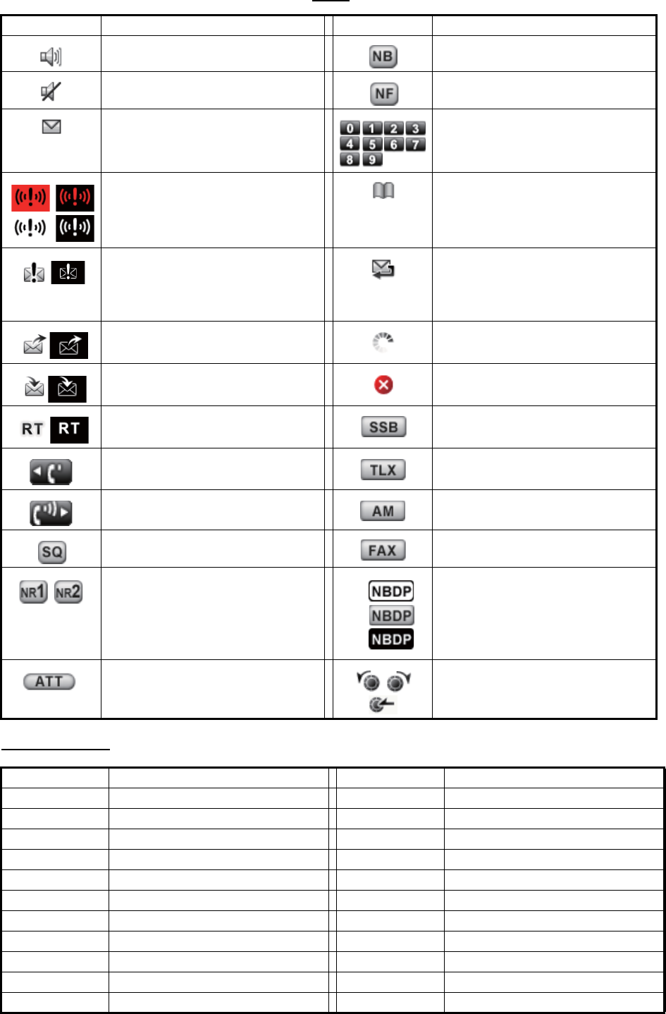
APPENDIX 3 LIST OF ABBREVIATIONS
AP-17
Icons
Telex (NBDP)
Icon Meaning Icon Meaning
Speaker ON Noise blanker ON
Speaker OFF Notch filter ON
Unread message Number keys
Send a distress alert of your
ship.
Name of the ship registerd in ad-
dress book
• Receive a distress alert from
a ship in distress.
• Send a distress relay on be-
half of a ship in distress.
Auto ACK for individual mes-
sage is ON.
Send a general (safety, urgency
or routine) message.
Data is being updated regularly.
Receive a general (safety, ur-
gency or routine) message.
Unsolved error
Communicate via radiotele-
phone
Class of emission is SSB.
Turn down the handset volume. Class of emission is TLX.
Turn up the handset volume. Class of emission is AM.
Squelch ON Class of emission is FAX.
Noise reduction: NR1 (Low),
NR2 (High)
Class of emission is NBDP.
1: Watch
2: Scan
3: Communication
Attenuator ON ENTER knob
Abbreviation Meaning Abbreviation Meaning
ACK Acknowledge CFM Confirm
ADV Advise CH Channel
AGN Again COL Collation
Alt Alternative Comm Mode Communication Mode
Apr April Comm Status Communication Status
ARQ Automatic Repetition request CRV How do you receive?
Aug August Ctrl Control
BI (GS) Good bye Dec December
BK I cut off. DER Out of order
Caps Capital and Small Dir Direction
CFEC Collective FEC DSC Digital Selective Call
1
2
3

APPENDIX 3 LIST OF ABBREVIATIONS
AP-18
DWN Down Over Change-over
EEE Error P (or 0) Stop your transmission.
Eng English PLS (PSE) Please
Esc Escape PPR Paper
Feb February Prt Scr Print Screen
FEC Forward Error Correcting R (RCD) Received
FM From RAP I will call you again.
Fn Function RD Read
Freq Frequency RE Referring to
Fri Friday RPT Repeat
GA Go ahead. Rus Russian
HR Here is RX Receiving
ID Identification Data Sat Saturday
Jan January ScrLk Scroll Lock
JST Japanese Standard Time SD Secure Digital
Jul July sec second
Jun June Sep September
Mar March SFEC Selective FEC
MNS Minutes SIO Serial Input and Output
MOM Wait (Waiting) SMT Ship’s Mean Time
Mon Monday SRY Sorry
msec milli second Sun Sunday
MSG Message SVP Please
MUTI Mutilated TAX What is the charge?
NA Correspondence to this sub-
scriber is not admitted.
TEST MSG Please send a test message?
NBDP Narrow Band Direct Print THRU You are in communication with
telex position.
NC No circuits Thu Thursday
NCH Subscriber’s number has been
changed.
TKS (TNX) Thanks
NG Non-Good TLX Telex
Nov November T.op Timer Operation
NP The called party is not or no
longer is a subscriber.
Tue Tuesday
NR Indicate your call number. TX Transmission
Num Number USB Universal Serial Bus
NumLk Numerical Key Lock UTC Coordinated Universal Time/
Universal Time, Coordinated
OCC Subscriber is engaged. Ver Version
Oct October Wed Wednesday
OK Okey WRU Who are you
Abbreviation Meaning Abbreviation Meaning

AP-19
APPENDIX 4 DIGITAL INTERFACE
(IEC 61162-1)
I/O Sentences
Input sentences (IEC 61162-1)
GGA, GLL, ZDA, GNS, RMC
Input sentence description
• GGA - Global positioning system (GPS) fix data
• GLL - Geographic position - latitude/longitude
• ZDA - Time and date
$**GGA,hhmmss.ss,llll.lll,a,yyyyy.yyy,a,x,xx,x.x,x.x,M,x.x,M,x.x,xxxx*hh<CR><LF>
1 2 3 4 5 6 7 8 9 10 11 12 13 14
1. UTC of position (000000.00 - 235959.99)
2. Latitude (0000.0000 - 9000.0000)
3. N/S
4. Longitude (00000.0000 - 18000.0000)
5. E/W
6. GPS quality indicator (1 - 7)
7. Number of satllite in use (no use)
8. Horizontal dilution of precision (no use)
9. Antenna altitude above/below mean sealevel (no use)
10. Unit, m
11. Geoidal separation (no use)
12. Unit, m
13. Age of differential GPS data (no use)
14. Differential reference station ID (no use)
$**GLL,llll.lll,a,yyyyy.yyy,a,hhmmss.ss,a,x*hh<CR><LF>
1 2 3 4 5
6 7
1. Latitude (0000.0000 - 9000.0000)
2. N/S
3. Longitude (00000.0000 - 18000.0000)
4. E/W
5. UTC of position (000000.00 - 235959.99)
6. Status (A=data valid V=data invalid)
7. Mode indicator (A=Autonomous D=Differential
E=Estimated (dead reckoning) mode M=Manual input mode
N=No fix S=Simulator mode
$**ZDA,hhmmss.ss,xx,xx,xxxx,xx,xx*hh<CR><LF>
1 2 3 4 5 6
1. UTC (000000.00 - 235959.99)
2. Day (01 - 31)
3. Month (01 -12)
4. Year (2000 - 2049)
5. Local zone, hours (no use)
6. Loca zone, minutes (no use)

APPENDIX 4 DIGITAL INTERFACE (IEC 61162-1)
AP-20
• GNS - GNSS fix data
• RMC - Recommended minimum specific GNSS data
$**GNS,hhmmss.ss,llll.lll,a,IIIII.III,a,c--c,xx,x.x,x.x,x.x,x.x,x.x,a*hh<CR><LF>
1 2
3 4 5 6 7 8 9 10 11 12 13
1. UTC of position (000000.00 - 235959.99)
2. Latitude (0000.0000 - 9000.0000)
3. N/S
4. Longitude (00000.0000 - 18000.0000)
5. E/W
6. Mode indicator
N=No fix A=Autonomous D=Differential P=Precise R=Real Time Kinematic
F=Float RTK E=Estimated Mode M=Manual Input Mode S=Simulator Mode
7. Total number of satellites in use (00 - 99)
8. HDOP (no use)
9. Antenna altitude, meters (no use)
10. Geoidal separation (no use)
11. Age of differential data (no use)
12. Differential reference station ID (no use)
13. Navigational status indicator (S=Safe C=Caution U=Unsafe V=Navigational status not valid)
$**RMC,hhmmss.ss,A,llll.ll,a,yyyyy.yy,a,x.x,x.x,ddmmyy,x.x,a,a,a*hh<CR><LF>
1 2 3 4 5 6 7 8 9 10
11 12 13
1. UTC of position fix (000000.00 - 235959.99)
2. Status (A=data valid, V=navigation receiver warning)
3. Latitude (0000.0000 - 9000.0000)
4. N/S
5. Longitude (00000.0000 - 18000.0000)
6. E/W
7. Speed over ground, knots (no use)
8. Course over ground, degrees true (no use)
9. Date (010100 - 311249)
10. Magnetic variation, degrees (no use)
11. E/W
12. Mode indicator (A= Autonomous D= Differential E=Estimated (dead reckoning) mode
F=Float RTK M=Manual input mode N=No fix P=Precise R=Real time kinematic S=Simulator mode
13. Navigational status indicator (S=Safe C=Caution U=Unsafe V=Navigational status not valid)

APPENDIX 4 DIGITAL INTERFACE (IEC 61162-1)
AP-21
Output sentences (IEC 61162-1)
DSC, DSE
Output sentence description
• DSC - Digital selective calling information
• DSE - Expanded digital selective calling
$CTDSC,xx,xxxxxxxxxx,xx,xx,xx,x.x,x.x,xxxxxxxxxx,xx,a,a*hh<CR><LF>
1 2 3 4 5 6 7 8 9
10 11
1. Format specifier (2 digits)
2. Address (10 digits)
3. Category (2 digits or NULL)
4. Nature of Distress or first telecommand (2 digits or NULL)
5. Type of Communication or second telecommand (2 digits)
6. Position or Channel /Frequency (Max. 4 digits)
7. Time or Tel. No. (Max. 16 digits)
8. MMSI of ship in distress (10 digits or NULL)
9. Nature of distress (2 digits or NULL)
10. Acknowledgement (R=Acknowledge request B=Acknowledgement S=Neither (end of sequence)
11. Expansion indicator (E or NULL)
$CTDSE,x,x,a,xxxxxxxxxx,xx,c--c,..........,xx,c--c*hh<CR><LF>
1 2 3 4 5 6 7 8 9
1. Total number of sentences (fixed value)
2. Sentence number (fixed value)
3. Query/reply flag (fixed value A=Automatic)
4. Vessel MMSI (10 digits)
5. Data set ‘1’ (code field, fixed value 00)
6. Data set ‘1’ (data field, Enhanced position resolution, Max. 8 characters)
7. Additional data sets*
8. Data set ‘n’ (code field)*
9. Data set ‘n’ (data field)*
*: This equipment outputs only “Data set 1”.
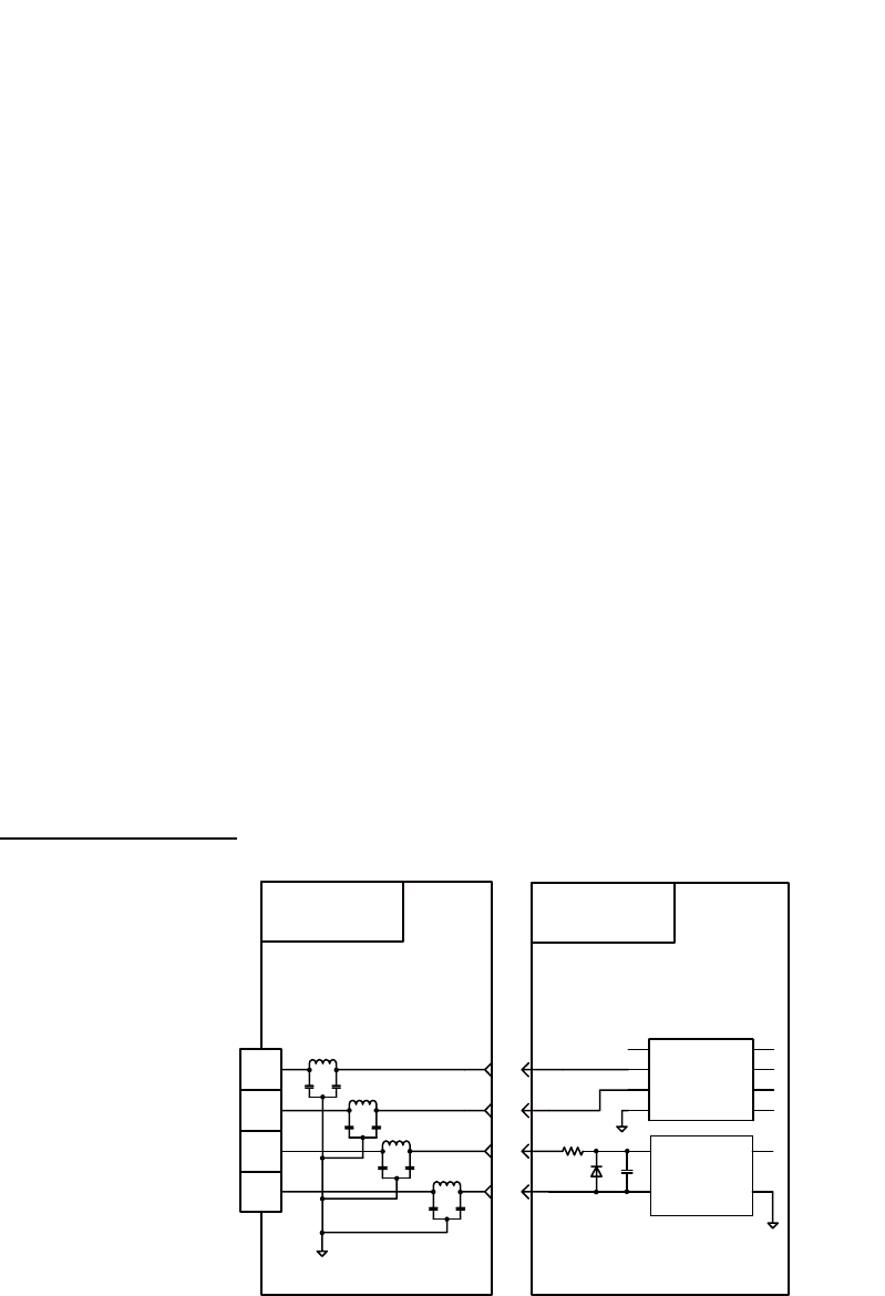
APPENDIX 4 DIGITAL INTERFACE (IEC 61162-1)
AP-22
P - sentences
pireq (input), pidat (output)
P - sentence description
• PFEC,pireq - Equipment information request
When this sentence is input, the equipment outputs the PFEC,pidat sentence.
• PFEC,pidat - Equipment information
Schematic diagram
Load requirements as a listener
Isolation: Optocoupler Input impedance: 470Ω Max. voltage: ±15 V Threshold: 4 mA
$ PFEC, pireq *hh<CR><LF>
$ PFEC,pidat, 0, FS-xxxx *hh<CR><LF>
1 2
1. ID (fixed value)
2. Model name (FS-1575, FS-2575, FS-5075)
$ PFEC,pidat, 1, 01.01 *hh<CR><LF>
1 2
1. ID (fixed value)
2. Software version (00.00 - 99.99)
$ PFEC,pidat, 4, 0000, 0000, 4000, 0000, 0000, 0000, 0000, 0000 *hh<CR><LF>
1 2 3 4 5 6 7 8 9
1. ID (fixed value)
2 to 9. Unit division code (fixed value)
$ PFEC,pidat, 5, 0, *hh<CR><LF>
1 2
1. ID (fixed value)
2. Browser control (fixed value)
TD-A
TD-B
RD-A
RD-B
T-IF
05P0861
J1
TB6
R254
470Ω
FL5
MOT
05P0860
J7
1
2
3
4
FL6
FL7
FL9
9
10
11
12
8
7
6
5
1
3
U3
SN65HVD10DR
U6
PC400
4
3
2
1
4
5
CR4
1SS355
C240
100pF
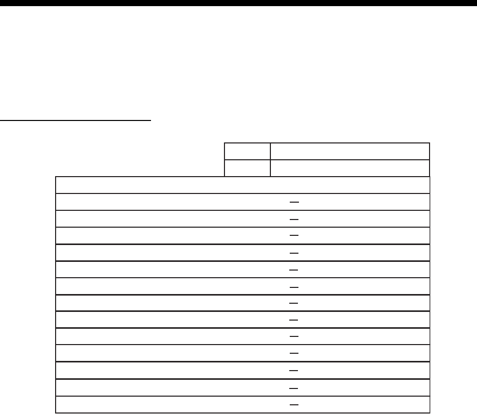
AP-23
APPENDIX 5 PARTS LIST
This equipment contains complex modules in which fault diagnosis and repair down to component
level are not practical (IMO A.694(17)/8.3.1). Only some discrete components are used. FURUNO
Electric Co., Ltd. Believes identifying these components is of no value for shipboard maintenance;
therefore, they are not listed in this manual. Major modules can be located on the parts location
photos on pages AP-25 thru AP-27.
Transceiver unit FS-1575T
Unit
Model
Code No.
ELECTRICAL PARTS LIST FS-1575
Transceiver Unit FS-1575T
05P0864, LF
05P0868, PA
05P0874, PWR
05P0847A, WR1
05P0856, TX
05P0842, RX
05P0862B, RX-FIL
05P0861, T-IF
05P0860, MOT
05P0859, T-CPU
05P0871, P-SW
05P0847B, WR2
05P0876A, TX-FIL
PRINTED CIRCUIT BOARD
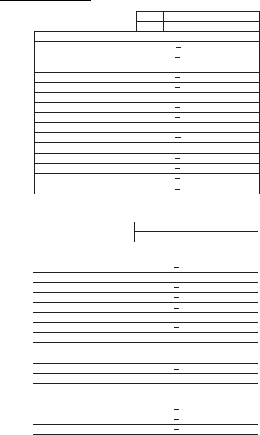
APPENDIX 5 PARTS LIST
AP-24
Transceiver unit FS-2575T
Transceiver unit FS-5075T
Unit
Model
Code No.
ELECTRICAL PARTS LIST
FS-2575
Transceiver Unit FS-2575T
05P0873, SW-REG
05P0866B, DRV
05P0867B, PA
05P0874, PWR
05P0864, PA-IF
05P0847A, WR1
05P0856, TX
05P0842, RX
05P0862B, RX-FIL
05P0861, T-IF
05P0860, MOT
05P0859, T-CPU
05P0871, P-SW
05P0847B, WR2
05P0870B, TX-FIL
PRINTED CIRCUIT BOARD
Unit
Model
Code No.
ELECTRICAL PARTS LIST FS-5075
Transceiver Unit FS-5075T
05P0867A, PA
05P0866A, DRV
05P0873, SW-REG
05P0869, COMB
05P0872, FET
05P0871, P-SW
05P0874, PWR
05P0847A, WR1
05P0856, TX
05P0842, RX
05P0863, DUP-FIL
05P0861, T-IF
05P0860, MOT
05P0859, T-CPU
05P0864, PA-IF
05P0847B, WR2
05P0862A, RX-FIL
05P0870A, TX-FIL
PRINTED CIRCUIT BOARD
APPENDIX 5 PARTS LIST
AP-25
Control unit FS-2575C
Antenna Coupler AT-1575
Antenna Coupler AT-5075
Unit
Model
Code No.
ELECTRICAL PARTS LIST
FS-1575, FS-2575, FS-5075
Control Unit FS-2575C
05P0844, PANEL
05P0853, C-IF
05P0852, C-CPU
PRINTED CIRCUIT BOARD
Unit
Model
Code No.
ELECTRICAL PARTS LIST FS-1575
Antenna Coupler AT-1575
05P0883, COUP
PRINTED CIRCUIT BOARD
Unit
Model
Code No.
ELECTRICAL PARTS LIST
FS-2575, FS--5075
Antenna Coupler AT-5075
05P0875, COUP
PRINTED CIRCUIT BOARD
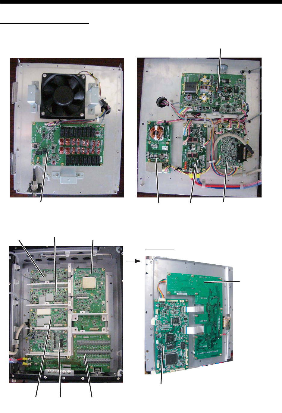
AP-26
APPENDIX 6 PARTS LOCATION
Transceiver unit FS-1575T
05P0868
150WPA
05P0874
PWR
05P0871
P-SW
05P0864A
PA-IF
05P0856
TX
05P0842
RX
05P0862B
RX-FIL
05P0861A
T-IF
Rear side
05P0860
MOT
05P0859
T-CPU
05P0847B
WR2
05P0876
150WTX-FIL
05P0847A
WR1
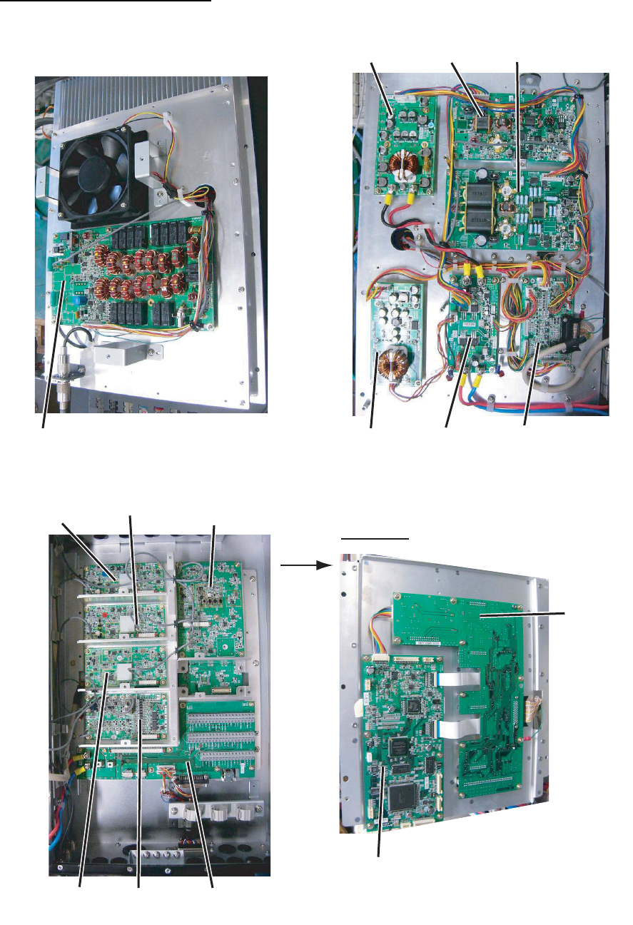
APPENDIX 6 PARTS LOCATION
AP-27
Transceiver unit FS-2575T
05P0873
SW-REG
05P0866B
DRV
05P0867B
PA
05P0874
PWR
05P0871
P-SW
05P0864
PA-IF
05P0847B
WR2
05P0856
TX
05P0842
RX
05P0862B
RX-FIL
05P0861
T-IF
Rear side
05P0860
MOT
05P0859
T-CPU
05P0847A
WR1
05P0870B
TX-FIL
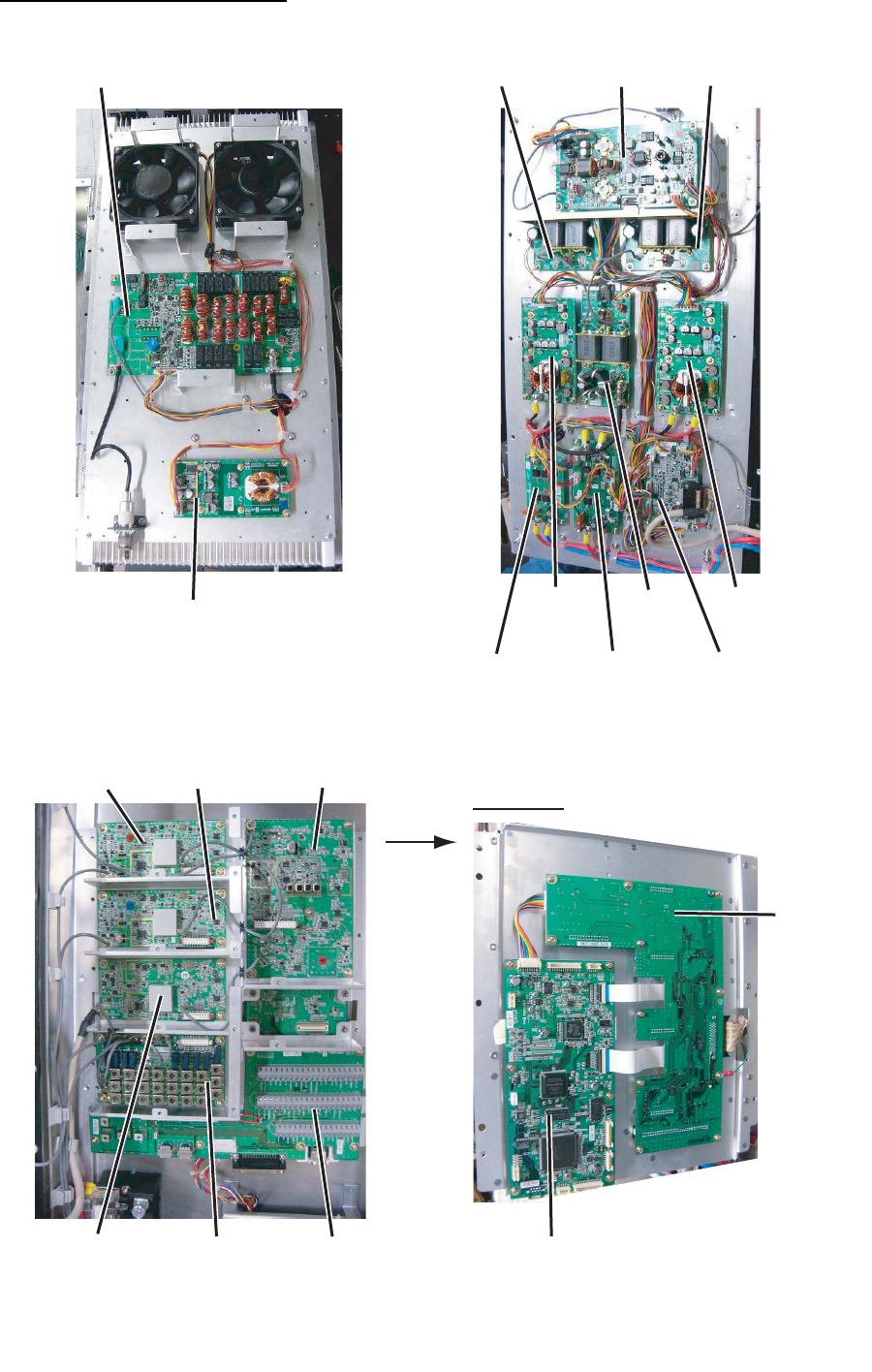
APPENDIX 6 PARTS LOCATION
AP-28
Transceiver unit FS-5075T
05P0867A
PA
05P0866A
DRV 05P0867A
PA
05P0872
FET
05P0871
P-SW 05P0864
PA-IF
05P0847B
WR2
05P0856
TX
05P0842
RX - 05P0863
DUP-FIL
- 05P0862A
RX-FIL
(underneath
DUP-FIL Board)
05P0861
T-IF
Rear side
05P0860
MOT
05P0859
T-CPU
05P0873
SW-REG
05P0873
SW-REG 05P0869
COMB
05P0874
PWR
05P0870A
TX-FIL
05P0847A
WR1
APPENDIX 6 PARTS LOCATION
AP-29
Control unit FS-2575C
Antenna coupler AT-1575
05P0844 (PANEL)
05P0853 (C-IF)
05P0852 (C-CPU)
05P0883
COUP
APPENDIX 6 PARTS LOCATION
AP-30
Antenna coupler AT-5075
05P0875
COUP

FURUNO
FS-1575/2575/5075
SP - 1 E5678S01G-M
SPECIFICATIONS OF SSB RADIOTELEPHONE
FS-1575/2575/5075
1 MF/HF DIGITAL RADIOTELEPHONE
1.1 GENERAL
1.1.1 Communication system
FS-1575/2575 Semi-duplex or simplex
FS-5075 Full-duplex (option required), semi-duplex or simplex
1.1.2 Class of emission J3E: Telephone
F1B (J2B): DSC and NBDP
H3E: reception only
A1A, F3C: requires settings for communications
1.1.3 Number of channel User programmable: 256 TX/RX pairs
All ITU channels incorporated (include DSC/NBDP), SSB, TLX, CW
1.1.4 Warming up 1 minute approx. (oven 15 minutes approx.)
1.2 TRANSMITTER
1.2.1 Frequency range 1,605 kHz to 27.5 MHz (100 Hz step)
1.2.2 RF output power
FS-1575 MF/HF: 150 Wpep
FS-2575 MF/HF: 250 Wpep
FS-5075 MF: 400 Wpep, HF: 500 Wpep
1.2.3 Frequency stability ±10 Hz
1.2.4 MIC in sensitivity 1 kHz, 94 dBA maximum power: -9 dB to -3 dB
1.2.5 Line in sensitivity 1 kHz, -16 dBm maximum power: -9 dB to -3 dB
1.2.6 Audio frequency range 350 Hz to 2.7 kHz (within 6dB)
1.3 RECEIVER
1.3.1 Receiving system Double-conversion superheterodyne
1.3.2 Frequency range 100 kHz-29,999.99 kHz (10 Hz step)
1.3.3 Sensitivity (SINAD 20 dB)
Frequency Range J3E
100 kHz to 300 kHz 35 dBµV
300 kHz to 1.6 MHz 25 dBµV
1.6 MHz to 4.0 MHz 13 dBµV
4.0 MHz to 30 MHz 7 dBµV
1.3.4 Intermediate frequency 1st: 53.964 kHz, 2nd: 36 kHz
1.3.5 Spurious response Better than 60 dB
1.3.6 Audio output power Speaker: 3 W/4 ohm
Handset: 10 mW/150 ohm
Line output: 0 dBm/600 ohm
1.3.7 Standard features AGC, Noise blanker, Voice-activated squelch, Noise reduction,
Notch filter, Attenuator
FURUNO
FS-1575/2575/5075
SP - 2 E5678S01G-M
2 DSC/WATCH KEEPING RECEIVER
2.1 DIGITAL SELECTIVE CALLING
2.1.1 Frequency shift Mark: F-85Hz, Space: F+85 Hz (F: assigned frequency)
2.1.2 Baud rate 100 bps ± 30 x 10-6
2.1.3 Protocol ITU-R Rec.493-13, 541-9
2.1.4 Modulation FSK
2.2 DSC/WATCH RECEIVER (DISTRESS)
2.2.1 Frequency range 2187.5/ 4207.5/ 6312.0/ 8414.5/ 12577.0/ 16804.5 kHz
2.2.2 Class of emission F1B (J2B)
2.2.3 Antenna impedance 50 ohm
2.2.4 Sensitivity 0 dBμV or less
2.2.5 Intermediate frequency 1st: 35.964 MHz, 2nd: 36 kHz
2.2.6 Frequency stability ±10 Hz
2.2.7 Output power for preamp 12 VDC: 0.15 A max.
2.2.8 Spurious response Better than 60 dB
2.3 DSC/WATCH RECEIVER (GENERAL FREQUENCY, OPTION)
2.3.1 Frequency range 1605 kHz to 27.5 MHz
2.3.2 Class of emission F1B (J2B)
2.3.3 Antenna impedance 50 ohm
2.3.4 Sensitivity 0 dBμV or less
2.3.5 Intermediate frequency 1st: 44.964 MHz, 2nd: 36 kHz
2.3.6 Output power for preamp 12 VDC: 0.15 A max.
2.3.7 Spurious response Better than 60 dB
3 NBDP FUNCTION (OPTION)
3.1 Communication mode ARQ, FEC
3.2 Protocol ITU-R M625-3, M476-5, M490, M491-1, M492-6
3.3 Modulation FSK
4 CONTROL UNIT
4.1 Display system 4.3-inch color dot matrix
4.2 Pixel 480 x 272 dots
4.3 Brilliance 18 steps (off to maximum brightness)
4.4 Built-in speaker 4 ohms
4.5 Alarm volume 80 to 85 dB(A)
4.6 Visible distance 0.7 m nominal
5 ANTENNA COUPLER
5.1 Tuning system CPU controlled fully automatic tuning system
5.2 Frequency range 1605 kHz to 27.5 MHz
5.3 Input impedance 50 ohm
5.4 Antenna 10 m to 18 m wire or 10 m whip, or
8 m whip + horizontal feeder 2 m or more
FURUNO
FS-1575/2575/5075
SP - 3 E5678S01G-M
5.5 Tuning time Within 15 seconds
6 TERMINAL UNIT (OPTION)
6.1 Display
IB-583 10.4” color TFT LCD, 640 x 480 dots (VGA)
IB-585 10.4” color TFT LCD, 800 x 600 dots (SVGA)
6.2 Brilliance IB-583: 8 steps, IB-585: 11 steps
6.3 External memory
IB-583 3.5” floppy disk
IB-585 SD card: 2 GB max.
6.4 Visible distance 0.7 m nominal
7 INTERFACE
7.1 Input data sentences IEC 61162-1 Ed.4 (2010-11)
Ship’s Position (L/L) GGA, GLL, GNS, RMC
Time ZDA
7.2 LAN Ethernet 10Base-T/100Base-TX
8 POWER SUPPLY
8.1 Transceiver/control unit
FS-1575 24 VDC: 5A (RX), 20 A max. (TX)
FS-2575 24 VDC: 5A (RX), 40 A max. (TX)
FS-5075 24 VDC: 5A (RX), 60 A max. (TX)
8.2 Terminal unit 24 VDC: 0.6 A (IB-583), 12-24 VDC: 0.5-0.3 A (IB-585)
8.3 Printer (PP-510, option) 24 VDC: 1.5 A
8.4 AC/DC power supply unit
PR-300 (for FS-1575, option) 100/110/200/220VAC, 1 phase, 50/60 Hz
PR-850A (for FS-2575/5075, option)
100/110/120/200/220/240VAC, 1 phase, 50/60 Hz
9 ENVIRONMENTAL CONDITION
9.1 Ambient temperature
Antenna coupler -25°C to +55°C
Indoor units -15°C to +55°C
9.2 Relative humidity 93% or less at 40°C
9.3 Degree of protection
Antenna coupler IP56
Transceiver unit IP22 (bulkhead mount only)
Terminal unit IP22
Control unit IP20 (IP22: option required)
9.4 Vibration IEC60945 Ed.4
10 COATING COLOR
10.1 Antenna coupler N9.5 (white)
10.2 Transceiver/control unit N3.0

IN-1
INDEX
A
Abbreviation ..........................................AP-16
Address book
deleting...................................................6-15
editing.....................................................6-14
list...........................................................6-13
registration .............................................6-13
Alarm lists ................................................6-24
Antenna selection ....................................6-11
Area message
receiving.................................................5-14
sending...................................................5-12
Attenuator ..................................................2-6
Audio alarms ..............................................3-2
Auto ACK setting......................................6-21
B
Brilliance ....................................................1-4
C
Channel setting ..........................................2-2
Clarifier setting .........................................6-11
Class of emission.......................................2-1
Control description .....................................1-1
D
Daily test ..................................................11-1
Date and time setting .................................6-9
Digital interface .....................................AP-19
Distress alert
canceling ................................................4-15
receiving...................................................4-6
sending.....................................................4-1
Distress relay
receiving.................................................4-14
sending...................................................4-11
DSC frequency setting ...............................5-2
DSC message............................................3-1
DSC scan screen .......................................1-3
E
Error message .........................................11-4
External alarm setting ..............................6-12
F
FAX setting ..............................................6-10
Frequency setting ......................................2-2
Frequency table ......................................AP-3
G
Group message
receiving.................................................5-11
sending...................................................5-10
Group message preparation ....................6-18
I
Icon .......................................................AP-17
Individual message
receiving...................................................5-6
sending.....................................................5-1
Individual message preparation ...............6-17
Intercom .....................................................1-6
K
Key assignment .........................................6-7
L
Log file
deleting.....................................................6-6
opening ....................................................6-5
M
Maintenance ............................................11-3
Medical message
receiving.................................................5-18
sending...................................................5-17
MENU screen open/close ..........................6-1
Menu tree................................................AP-1
N
NBDP .........................................................7-1
abbreviation.........................................AP-18
answerback code registration ..................8-1
ARQ mode .............................................10-3
automatic telex .....................................10-15
creating file...............................................9-1
deleting file ...............................................9-7
Edit menu .................................................7-5
editing file .................................................9-3
enaming file..............................................9-7
FEC mode..............................................10-5
File menu .................................................7-4
ID code registration ..................................8-2
macrofile...............................................10-10
maintenance...........................................11-6
menu tree..............................................AP-2
Operate menu ..........................................7-5
printing file................................................9-8
reception mode ......................................10-5
saving file .................................................9-2
saving file under new name .....................9-7
scan channel group..................................8-6
scanning.................................................10-9
station list .................................................8-3
Station menu ............................................7-6
System menu ...........................................7-7
timer operation .......................................10-8
timer programming ...................................8-5
user channel.............................................8-2
Window menu ..........................................7-6
Network setting ........................................6-12
INDEX
IN-2
Neutral message
receiving ................................................ 5-16
sending.................................................. 5-14
Noise blanker ............................................ 2-5
Noise reduction ......................................... 2-5
Notch filter ................................................. 2-6
P
Parst list ................................................AP-23
Parst location ........................................AP-26
Polling request message......................... 5-19
Position message
eceiving ................................................. 5-22
sending.................................................. 5-20
Position setting.......................................... 6-8
Power on/off .............................................. 1-2
Printing message ...................................... 6-8
Priority ....................................................... 1-5
PSTN message
receiving ................................................ 5-25
sending.................................................. 5-23
PSTN message preparation.................... 6-18
R
RF gain...................................................... 2-5
RT screen.................................................. 1-2
S
Scanning frequency ......................... 1-4, 6-22
Session ..................................................... 1-7
S-meter ..................................................... 2-5
Sound setting .......................................... 6-23
Speaker..................................................... 1-4
Special message..................................... 6-22
Squelch ..................................................... 2-6
Squelch frequency .................................... 6-7
T
Test call................................................... 11-5
Test message preparation ...................... 6-19
Timeout setting........................................ 6-10
Tone test ................................................. 11-2
Transmission power .................................. 2-3
Troubleshooting ...................................... 11-4
TX self test .............................................. 11-2
U
User channel
deleting.................................................... 6-4
editing...................................................... 6-3
list ............................................................ 6-2
registration .............................................. 6-2
W
Working channel setting............................ 5-3
Working frequency setting......................... 5-3