Furuno USA 9ZWFS1575 GMDSS SSB User Manual FS1575 2575 5075 OME Frontcover
Furuno USA Inc GMDSS SSB FS1575 2575 5075 OME Frontcover
Contents
- 1. users manual part 1A
- 2. users manaul part 1B
- 3. users manual part 2
- 4. users manual part 3
users manual part 1A

SSB RADIOTELEPHONE
FS-1575
FS-2575
FS-5075
OPERATOR'S MANUAL
www.furuno.com
MODEL

The paper used in this manual
is elemental chlorine free.
・FURUNO Authorized Distributor/Dealer
9-52 Ashihara-cho,
Nishinomiya, 662-8580, JAPAN
Telephone : +81-(0)798-65-2111
Fax : +81-(0)798-65-4200
A : JUL 2011
.
Printed in Japan
All rights reserved.
Z4 : NOV . 30, 2011
Pub. No. OME-56770-Z4
(YOTA ) FS-2575/5075/1575

i
IMPORTANT NOTICES
General
• This manual has been authored with simplified grammar, to meet the needs of international us-
ers.
• The operator of this equipment must read and follow the descriptions in this manual. Wrong op-
eration or maintenance can cancel the warranty or cause injury.
• Do not copy any part of this manual without written permission from FURUNO.
• If this manual is lost or worn, contact your dealer about replacement.
• The contents of this manual and equipment specifications can change without notice.
• The example screens (or illustrations) shown in this manual can be different from the screens
you see on your display. The screens you see depend on your system configuration and equip-
ment settings.
• Save this manual for future reference.
• Any modification of the equipment (including software) by persons not authorized by FURUNO
will cancel the warranty.
• All brand and product names are trademarks, registered trademarks or service marks of their
respective holders.
How to discard this product
Discard this product according to local regulations for the disposal of industrial waste. For disposal
in the USA, see the homepage of the Electronics Industries Alliance (http://www.eiae.org/) for the
correct method of disposal.
How to discard a used battery
Some FURUNO products have a battery(ies). To see if your product has a battery, see the chapter
on Maintenance. Follow the instructions below if a battery is used. Tape the + and - terminals of
battery before disposal to prevent fire, heat generation caused by short circuit.
In the European Union
The crossed-out trash can symbol indicates that all types of batteries
must not be discarded in standard trash, or at a trash site. Take the
used batteries to a battery collection site according to your national
legislation and the Batteries Directive 2006/66/EU.
In the USA
The Mobius loop symbol (three chasing arrows) indicates that Ni-Cd
and lead-acid rechargeable batteries must be recycled. Take the
used batteries to a battery collection site according to local laws.
In the other countries
There are no international standards for the battery recycle symbol. The number of symbols can
increase when the other countries make their own recycle symbols in the future.
Cd
Ni-Cd Pb
ii
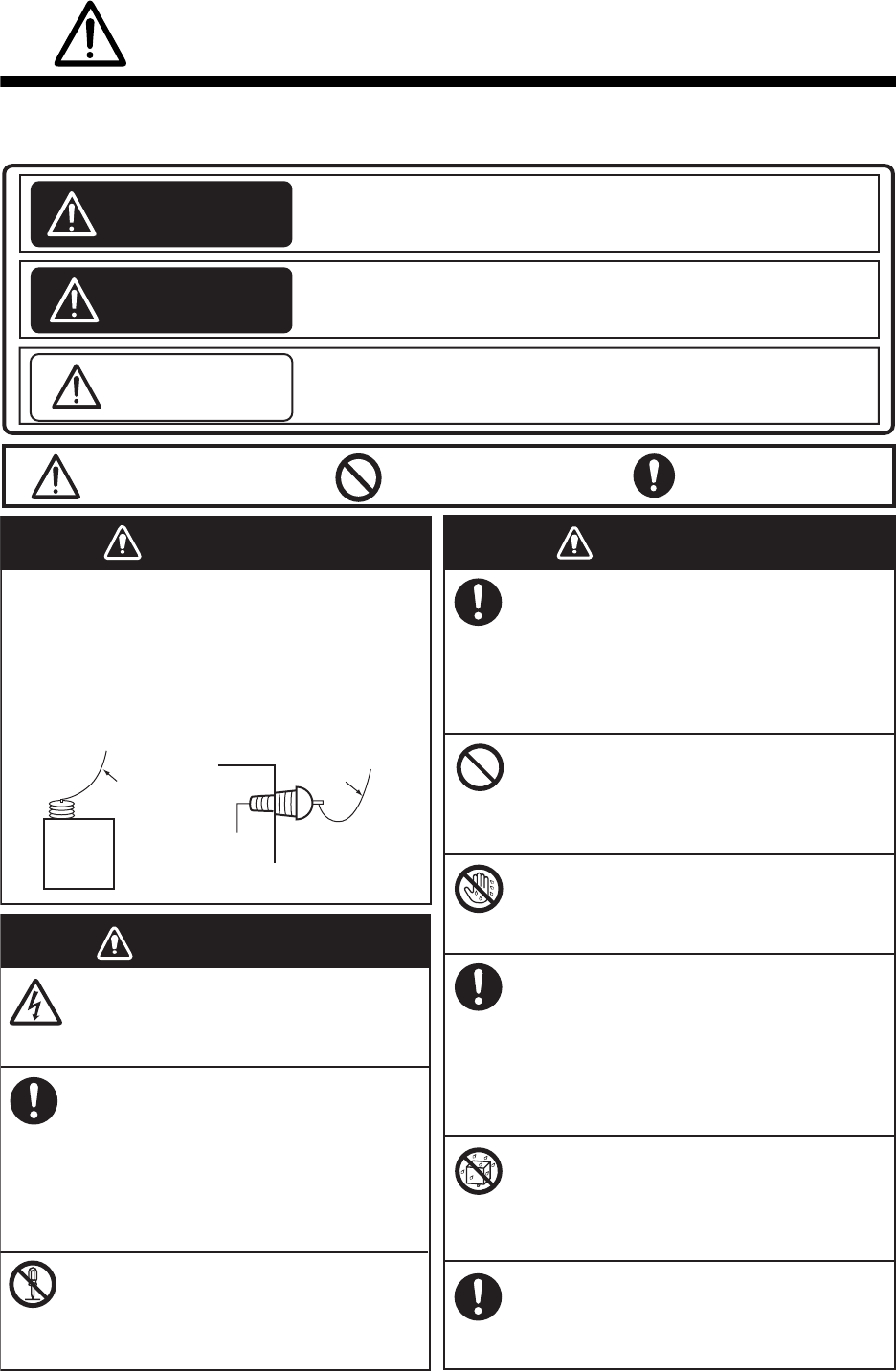
SAFETY INSTRUCTIONS
Indicates a condition that can cause death or serious injury
if not avoided.
Indicates a condition that can cause minor or moderate
injury if not avoided.
Indicates a condition that will result in death or serious injury
if not avoided.
The user and installer must read the appropriate safety instructions before attempting to install
or operate the equipment.
DANGER
WARNING
CAUTION
Warning, Caution Prohibitive Action Mandatory Action
DANGER
WARNING
WARNING
Never touch the SSB antenna, antenna
coupler or lead-in insulator when the
SSB radiotelephone is transmitting.
High voltage which will cause death or
serious injury is present at the locations
shown in the illustration below when the
SSB radiotelephone is transmitting.
Antenna
Coupler
Antenna Wire
(High Voltage)
Indoor Antenna
Wire
Lead-in
Insulator
(High
Voltage)
Do not open the equipment.
Only qualified personnel should work
inside the equipment.
Immediately turn off the power at
the switchboard if water leaks into
the equipment or something is
dropped into the equipment.
Continued use of the equipment can
cause fire or electrical shock. Contact
a FURUNO agent for service.
Do not disassemble or modify the
equipment.
Fire, electrical shock or serious injury
can result.
Immediately turn off the power at
the switchboard if the equipment is
emitting smoke or fire.
Continued use of the equipment can
cause fire or electrical shock. Contact
a FURUNO agent for service.
Do not place liquid-filled containers
on the top of the equipment.
Fire or electrical shock can result if a
liquid spills into the equipment.
Do not operate the equipment with
wet hands.
Electrical shock can result.
Turn off the power immediately if you
feel the equipment is behaving
abnormally.
Turn off the power at the switchboard if
the equipment becomes abnormally
warm or is emitting odd noises. Contact
a FURUNO dealer or agent for advice.
Make sure no rain or water splash
leaks into the equipment.
Fire or electrical shock can result if
water leaks in the equipment.
Use the proper fuse.
Use of the wrong fuse can cause fire or
electrical shock.
SAFETY INSTRUCTIONS
iii
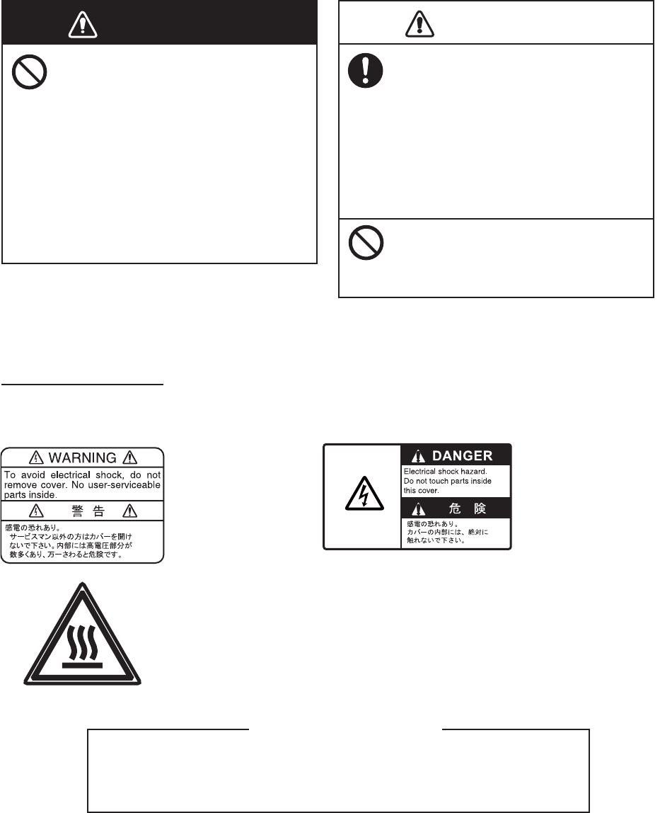
The TFT LCD is constructed using the latest LCD techniques, and displays
99.99% of its pixels. The remaining 0.01% of the pixels may drop out or
blink, however this is not an indication of malfunction.
About the TFT LCD
Warning labels are attached to the equipment. Do not remove any label. If a label is missing or
damaged, contact a FURUNO agent or dealer about replacement.
Name: Warning Label 1
Type: 86-003-1011-3
Code No.: 100-236-233-10
WARNING CAUTION
Do not operate the [DISTRESS]
key except in case of a
life-endangering situation on your
vessel.
Operating the [DISTRESS] key
transmits the distress alert.
Accidental transmission may prevent
search and rescue operations for
actual emergency. If the distress alert
is accidentally transmitted, contact
the nearest station to cancel the
alert.
If the distress alert is accidentally
transmitted, contact the nearest
coast station and inform them of the
accidental
transmission, providing the
following data:
a) Ship's name
b) Ship's call sign and DSC number
c) Position at time of transmission
d) Time of transmission
WARNING LABELS
Do not apply strong pressure to
the LCD, which is made of glass.
Injury can result if the LCD breaks.
Name: Warning Label
Type: 14-055-4202-1
Code No.: 100-245-221-10
Name: High Temp Warning Label
Type: 05-089-2142-0
Code No.: 100-301-620-10
iv
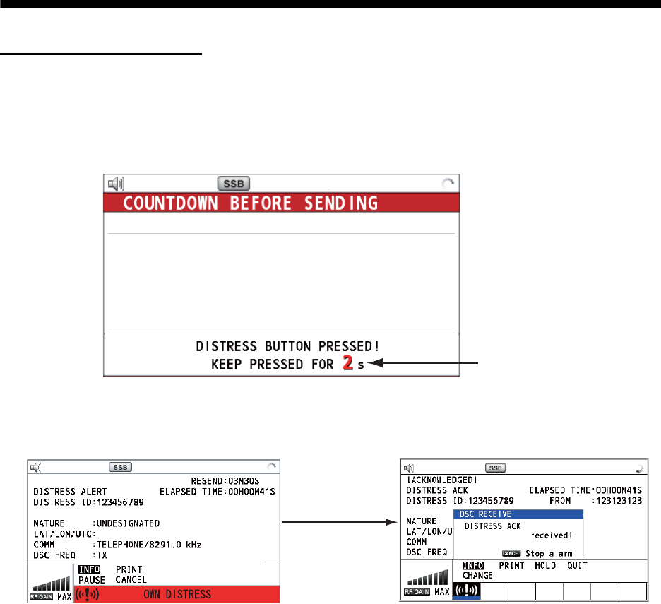
DISTRESS ALERT
How to send distress alert
Below is the procedure for transmitting a distress alert via radiotelephone. Transmit the distress
alert when a life-endangering situation occurs on your vessel.
1. Open the DISTRESS key cover then press the DISTRESS key for four seconds. The following
screen appears.
2. When the message "Sending DISTRESS ALERT." appears on the screen, release the DIS-
TRESS key. The audio alarm sounds for two seconds.
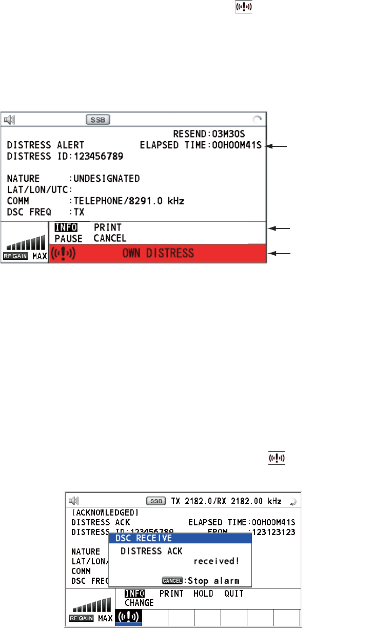
After the distress alert has been sent, the following screens appear in order.
3. The audio alarm sounds. Press the CANCEL key to silence the audio alarm.
4. Communicate with the coast station via radiotelephone as below.
a) Say “MAYDAY” three times.
b) Say “This is ...” name of your ship and call sign three times.
c) Give nature of distress and assistance needed.
d) Give description of your ship (type, color, number of persons onboard, etc.).
Note: If you do not receive the distress alert acknowledge call, the equipment automatically re-
transmits the distress alert after 3 min 30 seconds to 4 min 30 seconds. Then awaits the distress
alert acknowledge call. This is repeated until the distress alert is acknowledged.
Countdown
TX 2182 . 0 / RX 2182 . 00 kHz
MSG TYPE : DISTRESS ALERT
NATURE : UNDESIGNATED
LAT : 09
°
12.1234’ N
LON/UTC : 123
°
45.1234’ E /12 : 34
COMM MODE
: TELEPHONE
DSC FREQ : MULTI 2 4 6 8 12 16MHz
When distress
acknowledge
call is received
by coast station
PRINT
TX 2182 . 0 / RX 2182 . 00 kHz
09° 12.1234’ N/ 123° 45.1234’ E / 12 : 34
CHANGE
[ WAIT FOR ACK ]
TX 2182 . 0 / RX 2182 . 00 kHz
2, 4, 6, 8, 12, 16
MH
z
DISTRESS ALERT
v
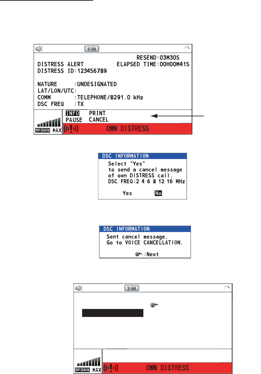
How to cancel distress alert
You can cancel the distress alert while it is being sent or while waiting for its acknowledgement as
follows.
1. Rotate the ENTER knob to select [CANCEL] in the user options area then push the knob.
The following message appears on the screen.
2. Rotate the ENTER knob to select [Yes] then push the knob to cancel the distress alert.
After transmitting the distress cancel call, the following message appears on the screen.
3. Push the ENTER knob to erase the message. The screen for the selection of frequency ap-
pears.
PRINT
TX 2182 . 0 / RX 2182 . 00 kHz
09° 12.1234’ N/ 123° 45.1234’ E / 12 : 34
CHANGE
[ WAIT FOR ACK ]
User options area
2, 4, 6, 8, 12, 16
MH
z
PRINT
TX 2182 . 0 / RX 2182 . 00 kHz
DISTRESS CANCEL MODE
SELECT FREQUENCY AND : ENTER
2M-2182.0kHz 8M- 8291.0kHz
4M-4125.0kHz 12M-12290.0kHz
6M-6215.0kHz 16M-16420.0kHz
DISTRESS ALERT
vi
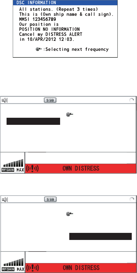
4. Rotate the ENTER knob to select a frequency then push the knob. The following message
appears on the screen.
5. Communicate with all ships via radiotelephone referring to the message at step 4.
6. Push the ENTER knob. The screen for the selection of frequency appears again. The frequen-
cy marked by asterisk shows that the call cancellation by voice was completed for that fre-
quency.
7. Repeat steps 4 through 6 to cancel for ALL frequencies. When cancellation on all frequencies
is completed, the options [Finish] and [Resend] appear.
8. Rotate the ENTER knob to select [Finish] then push the knob.
PRINT
TX 2182 . 0 / RX 2182 . 00 kHz
DISTRESS CANCEL MODE
SELECT FREQUENCY AND : ENTER
2M-2182.0kHz 8M- 8291.0kHz
4M-4125.0kHz 12M-12290.0kHz
6M-6215.0kHz 16M-16420.0kHz
*
PRINT
TX 16420 . 0 / RX 16420 . 00 kHz
DISTRESS CANCEL MODE
SELECT FREQUENCY AND : ENTER
2M-2182.0kHz 8M- 8291.0kHz
4M-4125.0kHz 12M-12290.0kHz
6M-6215.0kHz 16M-16420.0kHz
*
Finish Resend
*
*
*
**

vii
TABLE OF CONTENTS
FOREWORD................................................................................................................... xi
SYSTEM CONFIGURATIONS...................................................................................... xiii
1. OPERATIONAL OVERVIEW.................................................................................1-1
1.1 Controls ......................................................................................................................1-1
1.2 How to Turn On/Off the Power ...................................................................................1-2
1.3 Radiotelephone (RT) Screen......................................................................................1-2
1.4 DSC Scan Screen ......................................................................................................1-3
1.5 How to Adjust the Brilliance of the Display and Panel................................................1-4
1.6 How to Turn On/Off the Main Speaker .......................................................................1-4
1.7 How to Scan ...............................................................................................................1-4
1.8 How to Set the Auto Acknowledgement .....................................................................1-5
1.9 Control Unit Priority ....................................................................................................1-5
1.10 Intercom......................................................................................................................1-6
1.11 Operation of Session ..................................................................................................1-7
2. SSB RADIOTELEPHONE .....................................................................................2-1
2.1 How to Select the Class of Emission..........................................................................2-1
2.2 How to Select the Channel, Frequency......................................................................2-1
2.3 Transmission ..............................................................................................................2-3
2.3.1 Transmission procedure.................................................................................2-3
2.3.2 How to change transmission power ...............................................................2-3
2.3.3 Condition of the transmitter ............................................................................2-4
2.4 Reception ...................................................................................................................2-5
2.4.1 RF gain (sensitivity) adjustment .....................................................................2-5
2.4.2 S-meter...........................................................................................................2-5
2.4.3 Receive AM broadcasting stations .................................................................2-5
2.4.4 Noise blanker .................................................................................................2-5
2.4.5 Noise reduction ..............................................................................................2-5
2.4.6 Notch filter ......................................................................................................2-6
2.4.7 Squelch ..........................................................................................................2-6
2.4.8 Attenuator.......................................................................................................2-6
2.5 User Channels............................................................................................................2-6
3. DSC OVERVIEW ...................................................................................................3-1
3.1 What is DSC? .............................................................................................................3-1
3.2 DSC Message ............................................................................................................3-1
3.3 Audio Alarms ..............................................................................................................3-2
3.4 Description of Call Screens ........................................................................................3-3
3.4.1 RX calls ..........................................................................................................3-3
3.4.2 TX calls...........................................................................................................3-4
4. DSC DISTRESS OPERATIONS ............................................................................4-1
4.1 How to Send Distress Alert.........................................................................................4-1
4.1.1 How to send distress alert by DISTRESS key with distress information
not edited........................................................................................................4-1
4.1.2 How to send distress alert by DISTRESS key with distress information
edited..............................................................................................................4-3
4.2 How to Receive a Distress Alert .................................................................................4-6
4.2.1 Distress alert received on MF band................................................................4-6
4.2.2 Distress alert received on HF band ................................................................4-8
4.3 How to Send Distress Relay on Behalf of a Ship in Distress....................................4-11
TABLE OF CONTENTS
viii
4.3.1 How to send distress relay to coast station.................................................. 4-11
4.3.2 How to send distress relay to ships in your area.......................................... 4-12
4.4 How to Receive Distress Relay from Coast Station ................................................. 4-14
4.5 How to Cancel Distress Alert ................................................................................... 4-15
5. DSC GENERAL MESSAGE CALLING, RECEIVING............................................5-1
5.1 Individual Call.............................................................................................................5-1
5.1.1 How to send an individual call........................................................................ 5-1
5.1.2 How to receive an individual call .................................................................... 5-6
5.2 Group Call ................................................................................................................ 5-10
5.2.1 How to send a group call.............................................................................. 5-10
5.2.2 How to receive a group call.......................................................................... 5-11
5.3 Geographical Area Call............................................................................................ 5-12
5.3.1 How to send a geographical area call.......................................................... 5-12
5.3.2 How to receive a geographical area call ...................................................... 5-14
5.4 Neutral Craft Call...................................................................................................... 5-14
5.4.1 How to send a neutral craft call.................................................................... 5-14
5.4.2 How to receive a neutral craft call ................................................................ 5-16
5.5 Medical Transport Call ............................................................................................. 5-17
5.5.1 How to send a medical transport call ........................................................... 5-17
5.5.2 How to receive a medical transport call ....................................................... 5-18
5.6 How to Receive a Polling Request...........................................................................5-19
5.6.1 Automatic reply ............................................................................................ 5-19
5.6.2 Manual reply................................................................................................. 5-19
5.7 Position Call ............................................................................................................. 5-20
5.7.1 How to request other ship's position ............................................................ 5-20
5.7.2 Other ship requests your position ................................................................ 5-22
5.8 PSTN Call ................................................................................................................ 5-23
5.8.1 How to send a PSTN call ............................................................................. 5-23
5.8.2 How to receive a PSTN call ......................................................................... 5-25
6. MENU OPERATION...............................................................................................6-1
6.1 How to Open/Close the MENU Screen ...................................................................... 6-1
6.2 User Channels ........................................................................................................... 6-2
6.2.1 List for user channels.....................................................................................6-2
6.2.2 How to register user channels........................................................................ 6-2
6.2.3 How to edit user channels.............................................................................. 6-3
6.2.4 How to delete user channels.......................................................................... 6-4
6.2.5 How to sort the USER CH list by band........................................................... 6-4
6.2.6 How to select user channels for SSB mode................................................... 6-5
6.3 Log File ...................................................................................................................... 6-5
6.3.1 How to open a log file..................................................................................... 6-5
6.3.2 How to delete log files .................................................................................... 6-6
6.4 Squelch Frequency .................................................................................................... 6-7
6.5 Key Assignment ......................................................................................................... 6-7
6.6 How to Print Messages .............................................................................................. 6-8
6.7 Position Setting .......................................................................................................... 6-8
6.8 Date and Time Setting ............................................................................................... 6-9
6.9 Timeout Setting........................................................................................................6-10
6.10 FAX Enable/Disable................................................................................................. 6-10
6.11 How to Select the Antenna....................................................................................... 6-11
6.12 Clarifier Setting......................................................................................................... 6-11
6.13 External Alarm Setting ............................................................................................. 6-12
6.14 NETWORK Setting................................................................................................... 6-12
6.15 Address Book........................................................................................................... 6-13
6.15.1 List for address data..................................................................................... 6-13
TABLE OF CONTENTS
ix
6.15.2 How to register addresses............................................................................6-13
6.15.3 How to edit addresses..................................................................................6-14
6.15.4 How to delete addresses..............................................................................6-15
6.15.5 How to create a DSC message with registered address..............................6-15
6.16 TX Message Preparation..........................................................................................6-16
6.16.1 List for message files....................................................................................6-16
6.16.2 Individual calls ..............................................................................................6-17
6.16.3 Group calls ...................................................................................................6-18
6.16.4 PSTN calls....................................................................................................6-18
6.16.5 Test call ........................................................................................................6-19
6.16.6 How to edit prepared messages...................................................................6-19
6.16.7 How to send prepared messages.................................................................6-20
6.16.8 How to delete prepared messages...............................................................6-20
6.17 How to Set the AUTO ACK Details...........................................................................6-21
6.18 Special Messages ....................................................................................................6-22
6.19 How to Set Scan Frequencies ..................................................................................6-22
6.20 Sound Setting...........................................................................................................6-23
6.21 Alarm Lists................................................................................................................6-24
7. NBDP SYSTEM OVERVIEW .................................................................................7-1
7.1 How to Turn on the NBDP System .............................................................................7-1
7.2 Description of Equipment ...........................................................................................7-1
7.2.1 Terminal unit...................................................................................................7-1
7.2.2 Keyboard ........................................................................................................7-2
7.3 Function Keys, Menu Operation.................................................................................7-3
7.3.1 Menu conventions ..........................................................................................7-3
7.3.2 Menu overview ...............................................................................................7-4
7.3.3 Function key description.................................................................................7-4
8. NBDP PREPARATIONS........................................................................................8-1
8.1 Registration of Answerback & ID Codes ....................................................................8-1
8.1.1 How to register answerback code ..................................................................8-1
8.1.2 How to register ID codes ................................................................................8-2
8.2 User Channels............................................................................................................8-2
8.2.1 How to register user channels........................................................................8-2
8.2.2 How to edit/delete user channels ...................................................................8-3
8.3 Station List..................................................................................................................8-3
8.3.1 How to register stations..................................................................................8-3
8.3.2 How to edit/delete stations .............................................................................8-5
8.4 Timer Programming....................................................................................................8-5
8.4.1 How to register timer programs ......................................................................8-5
8.4.2 How to edit/delete timer programs .................................................................8-6
8.5 Scan Channel Groups ................................................................................................8-6
8.5.1 How to register scan channel groups .............................................................8-7
8.5.2 How to edit/delete scan channel groups ........................................................8-8
8.6 How to Change the Window Color .............................................................................8-9
8.7 Screen Saver Function for IB-585 ............................................................................8-10
9. NBDP FILE OPERATIONS....................................................................................9-1
9.1 How to Open and Close Files.....................................................................................9-1
9.2 How to Create Files ....................................................................................................9-1
9.3 How to Save a File .....................................................................................................9-2
9.3.1 How to format floppy disks or SD cards .........................................................9-2
9.3.2 How to save a file ...........................................................................................9-3
9.4 How to Edit Files.........................................................................................................9-3
9.4.1 How to cut and paste text...............................................................................9-3
TABLE OF CONTENTS
x
9.4.2 How to copy and paste text............................................................................ 9-4
9.4.3 Select all......................................................................................................... 9-4
9.4.4 How to search text ......................................................................................... 9-5
9.4.5 How to replace text ........................................................................................ 9-5
9.4.6 Goto line......................................................................................................... 9-6
9.4.7 Goto top, Goto bottom.................................................................................... 9-6
9.5 How to Open Files...................................................................................................... 9-6
9.5.1 Open a file...................................................................................................... 9-6
9.5.2 Switch between files....................................................................................... 9-7
9.6 How to Rename Files................................................................................................. 9-7
9.7 How to Save a File Under a New Name .................................................................... 9-7
9.8 How to Delete Files .................................................................................................... 9-8
9.9 Real Time Printing...................................................................................................... 9-8
9.10 How to Print Files ....................................................................................................... 9-8
10. NBDP TRANSMISSION, RECEPTION................................................................10-1
10.1 Manual Calling ......................................................................................................... 10-1
10.2 ARQ Mode Operation...............................................................................................10-3
10.3 FEC Mode Operation ............................................................................................... 10-5
10.4 How to Select Reception Mode................................................................................ 10-5
10.5 Communication Example ......................................................................................... 10-6
10.6 Timer Operation ....................................................................................................... 10-8
10.6.1 How to enable timer operation ..................................................................... 10-8
10.6.2 How to stop timer operation ......................................................................... 10-8
10.7 Scanning .................................................................................................................. 10-9
10.8 Communication Buffer.............................................................................................. 10-9
10.9 Preparation of Macrofiles for Automatic Telex .......................................................10-10
10.9.1 Automatic telex overview ........................................................................... 10-10
10.9.2 Preparations............................................................................................... 10-10
10.9.3 Commands................................................................................................. 10-11
10.9.4 Store-and-forward method ......................................................................... 10-13
10.10Automatic Telex Using Macrofile ........................................................................... 10-15
11. MAINTENANCE & TROUBLESHOOTING..........................................................11-1
11.1 Test .......................................................................................................................... 11-1
11.2 Maintenance............................................................................................................. 11-3
11.3 Simple Troubleshooting ........................................................................................... 11-4
11.4 Error Messages........................................................................................................ 11-4
11.5 Breaker on PR-850A ................................................................................................ 11-5
11.6 Test Call ...................................................................................................................11-5
11.7 NBDP Terminal Unit Maintenance ........................................................................... 11-6
11.7.1 Cleaning the equipment ............................................................................... 11-6
11.7.2 Connectors and earth connection ................................................................ 11-6
11.7.3 Floppy disk drive .......................................................................................... 11-6
11.7.4 Diagnostics................................................................................................... 11-6
APPENDIX 1 MENU TREE .......................................................................................AP-1
APPENDIX 2 FREQUENCY TABLES.......................................................................AP-3
APPENDIX 3 LIST OF ABBREVIATIONS..............................................................AP-16
APPENDIX 4 DIGITAL INTERFACE (IEC 61162-1) ...............................................AP-19
APPENDIX 5 PARTS LIST......................................................................................AP-23
APPENDIX 6 PARTS LOCATION...........................................................................AP-26
SPECIFICATIONS .....................................................................................................SP-1
INDEX.......................................................................................................................... IN-1

xi
FOREWORD
A Word to the Owner of the FS-1575/2575/5075
Congratulations on your choice of the FURUNO FS-1575/2575/5075 SSB Radiotelephone. We
are confident you will see why the FURUNO name has become synonymous with quality and re-
liability.
Since 1948, FURUNO Electric Company has enjoyed an enviable reputation for innovative and
dependable marine electronics equipment. This dedication to excellence is furthered by our ex-
tensive global network of agents and dealers.
Your equipment is designed and constructed to meet the rigorous demands of the marine envi-
ronment. However, no machine can perform its intended function unless properly installed and
maintained. Please carefully read and follow the operation and maintenance procedures set forth
in this manual.
We would appreciate feedback from you, the end-user, about whether we are achieving our pur-
poses.
Thank you for considering and purchasing FURUNO equipment.
Features
The FS-1575/2575/5075 is an MF/HF SSB Radiotelephone with a built-in DSC/Watch Receiver,
all contained in a surprisingly compact cabinet. An NBDP (Narrow Band Direct Printing) Terminal
Unit is optionally available.
Data is displayed on a large, easy-to-read color LCD. Operation is simplified by the use of few
keys and easy-to-follow menus.
The built-in DSC/Watch Receiver produces and receives digital selective callings for quick and ef-
ficient establishment of distress, urgency, safety and routine communications with other ships and
coast stations that install any MF/HF DSC facilities.
The main features are
General
• Fully meets the following regulations: IMO A.806(19), IMO A.694(17), MSC 36(63), MSC
68(68), IEC 61162-1 Ed.4, IEC 60945 Ed.4, ETS 300 067 Ed.1, EN 300 338, EN 300 373-1, EN
301 033, ITU-R M.476-5, ITU-R M.490, ITU-R M.491-1, ITU-R M.492-6, ITU-R M.493-13, ITU-
R M.541-9, ITU-R M.625-3, ITU-R M.821-1, ITU-R M.1082-1, ITU-R M.1173, MSC/Circ. 862.
• Automatic entry of position with manual override
• Optional printer can automatically print out DSC and NBDP received messages and test results.
DSC/Watch Receiver
• Distress, urgency, safety and routine calling
• Scanning of DSC frequencies for distress and general calls on MF/HF
• File editing capability for readiness in case of emergency
• PSTN (Public Switched Telephone Network) capability standard
FOREWORD
xii
• Log stores 50 each of latest general, distress and transmitted messages, in separate memory
blocks.
SSB
• Receiving voice communication
• Noise blanker function, Noise reduction function, Notch filter function, Squelch function are
available.
• Simplified setting of channel and frequency
NBDP (with optional NBDP Terminal Unit IB-583/IB-585)
• Automatic error-free telex communications and distress message in compliance with GMDSS
requirements
• LCD monitor and keyboard comply with ITU regulations
• Pop-up menus for user-friendly operation
• Memory for 256 operator-customized channels
• Real time message printing with Printer PP-510
Program Number
FS-1575/2575/5075
xx: minor change
Terminal Unit IB-583 (optional unit)
Terminal Unit IB-585 (optional unit)
Location PC board Program No. Version
FS-1575T/2575T/5075T T-CPU (05P0859) 0550243 (APP) 01.xx
0550247 (Boot) 01.xx
MOT (05P0860) 0550245 (CPLD) 01.xx
FS-2575C C-CPU (05P0852) 0550246 (Boot) 01.xx
ANTENNA COUPLER AT-5075 COUP (05P0875) 0550244 01.xx
ANTENNA COUPLER AT-1575 COUP (05P0883) 0550244 01.xx
PC board Program No. Version
TERMINAL 0550209 1.22
PC board Program No. Version
TERMINAL 0550251 01.xx
xiii
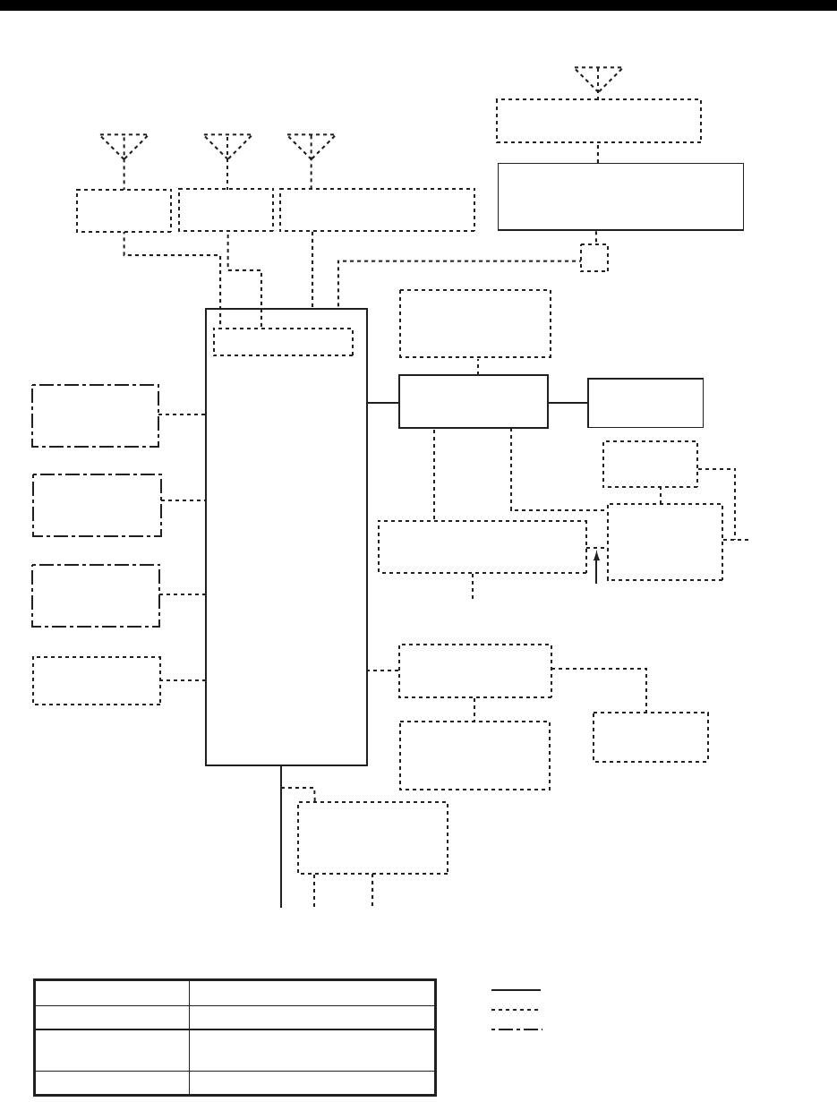
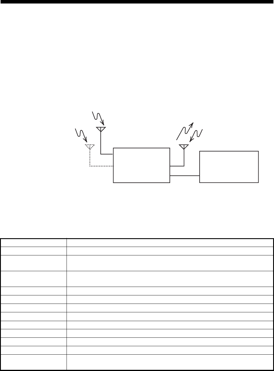
SYSTEM CONFIGURATIONS
*3
*1
*1ANTENNA COUPLER
AT-1575 (FS-1575) or
AT-5075 (FS-2575, FS-5075)
PRINTER
INTERFACE
IF-8500*2
PRINTER
PP-510
24
VDC
ALARM
SYSTEM
NAVIGATOR
EXTERNAL
EQUIPMENT
ALARM UNIT
IC-350
AUTOMATIC ANTENNA
SWITCH AS-102
EXTERNAL
LOUDSPEAKER
SEM-21Q
PREAMP
FAX-5
PREAMP
FAX-5
ANT. JUNC. BOX AJB1-1A or
MATCHING BOX ARD-1
*1 2.6 m whip
antenna
WR BOARD
TRANSCEIVER
UNIT
FS-1575T
(FS-1575)
or
FS-2575T
(FS-2575)
or
FS-5075T
(FS-5075)
CONTROL UNIT
FS-2575C
NBDP TERMINAL UNIT
IB-583 or IB-585
24 VDC *2 Required for NBDP Terminal
and DSC to share printer.
AC-DC POWER
SUPPLY UNIT
PR-850A
24 VDC 100/110/120/200/220/240 VAC
1
φ
, 50/60 Hz
: STANDARD
: OPTION
: LOCAL SUPPLY
Unit Category
Preamp Unit
Antenna Coupler
Other Units
Exposed to the weather
Exposed to the weather OR
protected from the weather
Protected from the weather
HANDSET
HS-2003
HANDSET
HS-2003
EXTERNAL
LOUDSPEAKER
SEM-21Q
BK INTERFACE
BK-300
*3 For DSC routine frequency
watch keeping receiver
No. 2 CONTROL
UNIT FS-2575C
*3
*1 2.6 m whip
antenna
For DSC
For NBDP
SYSTEM CONFIGURATIONS
xiv
This page is intentionally left blank.
1-1
1. OPERATIONAL OVERVIEW
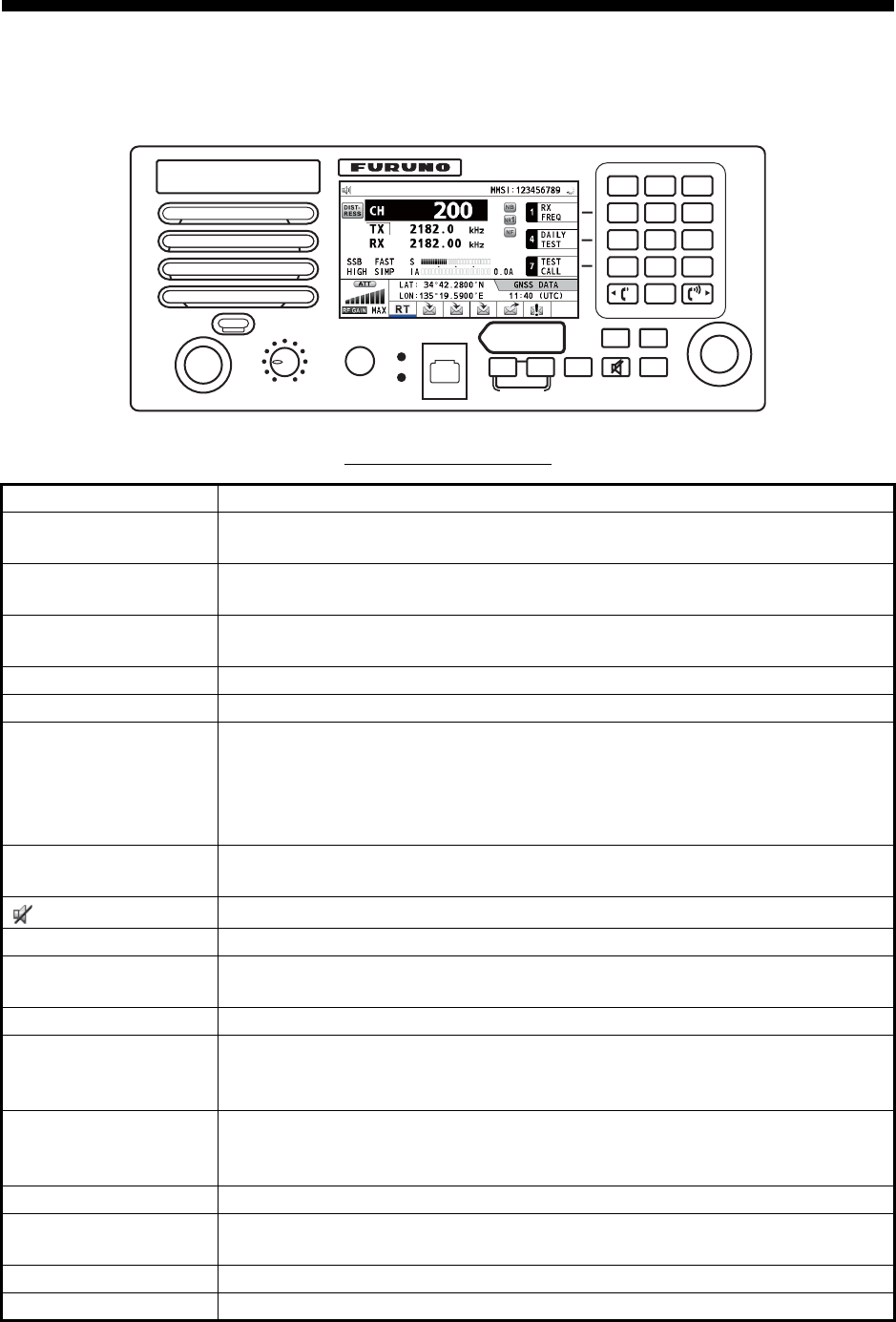
1.1 Controls
Description of controls
Control Function
VOLUME/PWR knob • Turns the power on or off.
• Adjusts the volume.
ENTER knob Rotate to select menu items or change the page in multi-page screens (e.g.,
log data); push to confirm a selection.
RF GAIN/
PUSH TO ATT knob
Rotate to adjust the gain; push to turn the attenuator on or off.
DISTRESS key Press and hold down the key four seconds to transmit the distress alert.
MENU key Opens/closes the menu.
CANCEL key • Cancels the creation of the DSC message currently being created.
• Silences the audio alarm.
• Erases error message or pop-up message.
• Returns one layer in multi-layer menu.
• Erases character input.
TAB key • Switches control to the tab area.
• Switches the session.
key Turns the main speaker on or off.
BRILL key Adjusts the brilliance.
OTHER DSC MSG
key
Composes DSC TX message except DISTRESS ALERT and DROBOSE
(Distress Relay On Behalf Of Someone Else).
DISTRESS MSG key Composes DSC TX message for DISTRESS ALERT.
DROBOSE MSG key Composes DSC TX message for DROBOSE (Distress Relay On Behalf Of
Someone Else). Press the DISTRESS MSG key and the OTHER DSC
MSG key simultaneously.
SCAN key • Opens the scan screen.
• Stops/starts the scanning of DSC routine frequencies, on the scan
screen.
2182 key Switches to the RT (radiotelephone) screen and sets freq. to 2182.0 kHz.
RT/CH key • Switches to the RT (radiotelephone) screen.
• Opens the CH setting window on the RT screen.
0 to 9 keys Enter alphabet, numeric or symbol.
1, 4 and 7 keys Execute the operation assigned to the function key in the RT mode.
SCAN 2182
RT/CH
12
NB
3
SQ
46
97
5
NR
8
NF
0
TUNE
COMPOSE
DROBOSE MSG
PUSH TO ENTER
DISTRESS
MSG OTHER
DSC MSG
BRILL
TAB MENU
CANCEL
HANDSET VOLUME
PWR OFF
RF GAIN
PUSH TO ATT
OVEN
ALARM
DISTRESS
Keep pressed for 4 sec in case
of DISTRESS. The alert is
transmitted with steady lighting.
1. OPERATIONAL OVERVIEW
1-2
1.2 How to Turn On/Off the Power
Rotate the VOLUME/PWR knob clockwise to turn on the power. The RT screen ap-
pears.
To turn off the power, rotate the VOLUME/PWR knob counterclockwise to the OFF po-
sition.
In the dual control unit system, the No.1 control unit has priority and it controls the
power for both itself and the No. 2 control unit. The power switch of the No. 2 control
unit powers on/off the No. 2 control unit only.
Note: Turn on the power at the switchboard more than five minutes before turning on
this equipment.
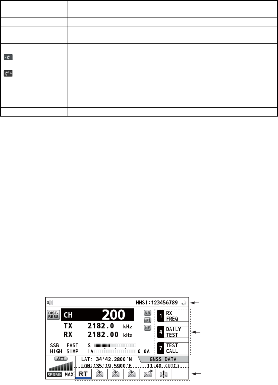
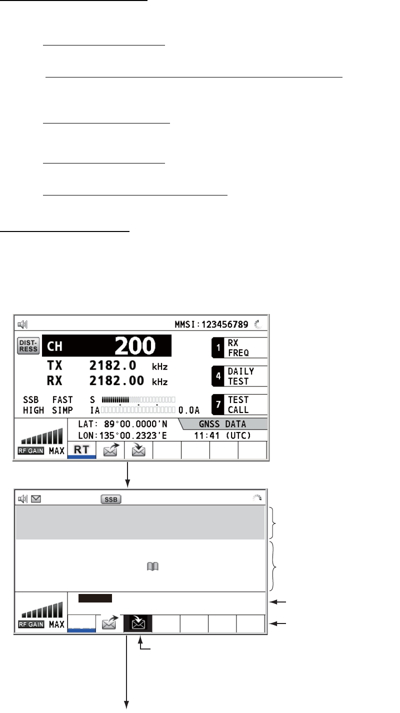
1.3 Radiotelephone (RT) Screen
Turn the power on, or press the RT/CH key to show the RT (radiotelephone) screen.
This is where you set up the transceiver unit, and communicate by voice or telex.
Radiotelephone (RT) screen
2/NB key Turns the noise blanker on or off in the RT mode.
3/SQ key Turns the squelch on or off in the RT mode.
5/NR key Reduces the noise in the RT mode (NR2 (High), NR1 (Low), Off).
8/NF key Turns the notch filter on or off in the RT mode.
0/TUNE key Tunes the antenna in radiotelephone operation.
key • Turns down the handset volume.
• Moves the cursor when setting channel or RX frequency.
key • Turns up the handset volume.
• Moves the cursor when setting channel or RX frequency.
ALARM lamp • Flashes in red for distress and urgency messages.
• Flashes in green for safety and routine messages, and when daily test is
completed.
OVEN lamp Lights in green when the main switchboard is on.
Control Function
Function keys
Tab area: Sessions
in progress
Spinner: Rotates when
the equipment is
functioning normally.
1. OPERATIONAL OVERVIEW
1-3
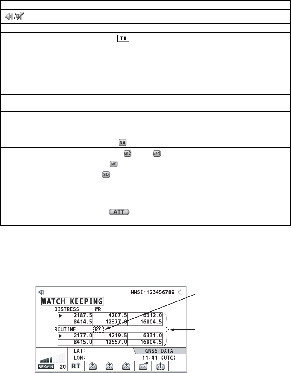
1.4 DSC Scan Screen
Press the SCAN key to show the DSC scan screen. This screen scans and receives
the distress and routine frequencies.
Indication Meaning
Main speaker on or off
CH Channel
TX TX frequency ( : while transmitting)
RX RX frequency
SSB/TLX/AM/FAX Class of emission
OFF/SLOW/FAST
(AGC)
Auto gain control ([OFF]: no adjustment, [SLOW]: low-speed, [FAST]: high-
speed)
HIGH/MID/LOW(1)/
LOW2
Output power ([LOW2]: FS-5075 only, minimum output power)
SIMP/S-DUP/DUP Communication mode ([SIMP]: simplex, [S-DUP]: semi-duplex, [DUP]: full-
duplex (only for FS-5075, option))
IA/IC/VC/RF/VS Transceiver unit status ([IA]: antenna current, [IC]: collector current,
[VC]: collector voltage, [RF]: RF output, [VS]: source voltage)
S S-meter, displays the strength of received signal.
NB Noise blanker ( :On, No indication: Off)
NR2/NR1/OFF Noise reduction ( : High, : Low, No indication: Off)
NF Notch filter ( : On, No indication: Off)
SQ Squelch ( : On, No indication: Off)
MMSI Own ship's ID (nine digits)
LAT, LON Own ship's position (LAT: Latitude, LON: Longitude)
GNSS UTC (universal time coordinated)
ATT Attenuator ( : On, No indication: Off)
RF GAIN Adjusted value of gain
Maximum six distress and
routine frequencies scanned.
RX: Transceiver unit
(WR2 shown when optional
antenna for routine frequencies
is installed.)
135°19
.
5900
'
E
34°42
.
2800
'
N
1. OPERATIONAL OVERVIEW
1-4
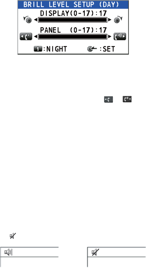
1.5 How to Adjust the Brilliance of the Display and
Panel
You can adjust the brilliance of the display and the panel as follows:
1. Press the BRILL key to show the [BRILL LEVEL SETUP] window.
2. Press the 1 key to switch the [DAY/NIGHT] mode.
3. To adjust the [DISPLAY] brilliance, rotate the ENTER knob or press the BRILL
key.
(Default setting: 17 for [DAY], 7 for [NIGHT])
4. To adjust the [PANEL] brilliance, press the or key.
(Default setting: 17 for [DAY], 12 for [NIGHT])
5. Push the ENTER knob to save the settings and close the window. To cancel the
settings, press the CANCEL key instead of the ENTER knob to close the window.
Note 1: The equipment keeps values for [DAY] and [NIGHT] separately.
Note 2: The window closes automatically when there is no operation for four seconds.
Note 3: When you turn on the power with the display brilliance set to 0, the setting au-
tomatically changes to 1.
1.6 How to Turn On/Off the Main Speaker
You can turn the main speaker (other than DSC communication, error, and key beep)
on/off.
1. Press the key to alternately disable or enable the main speaker.
2. To adjust the volume of the main speaker, rotate the VOLUME/PWR knob (cw:
volume up, ccw: volume down).
1.7 How to Scan
The DSC screen scans multiple routine frequencies according to operator-set interval.
For how to set frequency to scan, see section 6.19.
Note that voice and telex communication are not available when scanning.
Speaker ON Speaker OFF
1. OPERATIONAL OVERVIEW
1-5
1. Press the SCAN key to show the DSC scan screen. Scanning starts. When re-
ceiving the appropriate frequency signal, the scanning stops, and the frequency
is highlighted and flashes.
2. Press the SCAN key again to stop scanning the routine frequencies.
Note: You can not stop the scanning manually for the distress alert.
3. Rotate the ENTER knob to move the cursor to the desired routine frequency which
you want to watch. You can scan only the frequency selected by cursor.
4. Press the SCAN key to restart the scanning.
Note: When scanning starts, the active session (refer to section 1.11) is automatically
put on hold.
1.8 How to Set the Auto Acknowledgement
Individual, PSTN (public switched telephone network), position, polling and test calls
can be acknowledged automatically or manually. This is set on the [ACK SETTINGS]
in the [DSC] menu (see section 6.17).
Note: When own ship's communication is high priority, set to manual acknowledge-
ment.
The auto acknowledgement is not sent in the following cases:
• Other session is active (except individual call).
• There are RT or DSC sessions (for individual call).
• Channel is in use.
• ECC is NG (No Good).
Note: The auto acknowledgement for the individual call is sent only when the pro-
posed channel or communication mode is not available.
1.9 Control Unit Priority
If you operate the No.1 control unit while the No.2 control unit is being operated, the
right to operate is shifted to the No.1 control unit. The control unit not having priority
shows the following:
• The unit name currently in use: No.1 control unit, No.2 control unit or NBDP
• The ongoing operation: Composing messages, Transmitting, Communicating
The control unit which you operate has priority in the following conditions:
• The handset goes OFF HOOK.
• Display the menus or setting windows.
• Display each function screen (for example, Log).
• Press a key or rotate a knob. (The priority is lost after four seconds.)
• NBDP is communicating.

1. OPERATIONAL OVERVIEW
1-6
1.10 Intercom
The built-in intercom permits voice communications between two control units.
Calling
You can call over the intercom in on or off hook condition.
1. Press the MENU key.
2. Rotate the ENTER knob to select [INTERCOM] then push the knob. The pop-up
for calling appears and the called party's control unit rings. To cancel calling,
press the CANCEL key.
3. When the called party picks up their handset, the pop-up for calling disappears
and the INTERCOM CONNECTED screen appears. Start communications.
Note: You do not have to press the PTT switch to communicate.
4. If needed, adjust the handset volume with or key.
5. Hang up the handset or press the CANCEL key to turn the intercom off. The last-
used screen or the RT screen appears.
Answering
1. The control unit rings, and both the pop-up for calling and a message, which sug-
gests you to pick up the handset, appear. To cancel reply, press the CANCEL key.
2. Pick up the handset, and the alarm stops. The pop-up for calling disappears and
the INTERCOM CONNECTED screen appears. Start communications.
3. Hang up the handset or press the CANCEL key to turn the intercom off. The last-
used screen or the RT screen appears.
1. OPERATIONAL OVERVIEW
1-7
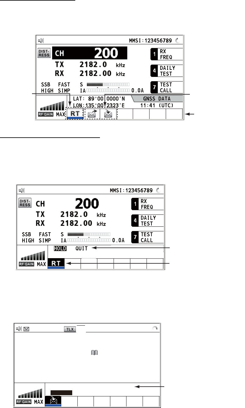
1.11 Operation of Session
Description of session
There are two types of sessions: RT session and DSC session. When a session starts,
the appropriate icon for the session appears in the tab area.
How to finish a single session
RT session
1. Press the TAB key to select the RT icon in the tab area.
2. Rotate the ENTER knob to select [QUIT] then push the knob.
DSC session
The cursor is in the tab area when the DSC session starts. Rotate the ENTER knob to
select [QUIT] then push the knob.
RT session DSC sessions
Tab area
Step 1: Press the TAB key
to select the RT icon.
Step 2: Rotate the ENTER
knob to select [QUIT].
[SELECT AN ACK]
ELAPSED TIME:
INDIVIDUAL MSG 00
H
00
M
58
S
FROM :
123456789
CAPTAIN_2575
COMM MODE :
TELEPHONE
COMM FREQ :
TX 2170.0 /RX 2170.0
kHz
INFO PRINT HOLD QUIT
ACCEPT UNABLE PROPOSE
TX 2177.0/ RX 2177.00 kHz
Rotate the ENTER knob
to select [QUIT].
1. OPERATIONAL OVERVIEW
1-8
How to start a new session
When another session is active:
• When sending the distress alert, all sessions except the distress alert TX session
automatically close then the distress alert TX session starts.
• When doing an RT session or sending a non-distress DSC message, the currently
active session is put on hold then the RT session or non-distress DSC message TX
session starts.
• When receiving a DSC message, its session is put on hold.
When no other session is active:
• When sending the distress alert, all sessions except the distress alert TX session
automatically close then the distress alert TX session starts.
• When sending a non-distress DSC message, its session becomes the active ses-
sion.
How to switch sessions
When one session is active and another message arrives, a new session for the re-
ceived message does not start automatically. Only one session can be active. For ex-
ample, when you are transmitting a DSC message and another message arrives, the
option [ACTIVE] appears to indicate the start of a new session.
[SELECT AN ACK]
INDIVIDUAL MSG ELAPSED TIME : 00H00M58S
FROM : 123456789 CAPTAIN_2575
COMM MODE : TELEPHONE
COMM FREQ : TX 2170.0 / RX 2170.0 kHz
ACTIVE INFO PRINT QUIT
TX 2182.0/ RX 2182.00 kHz
RT
Press the TAB key to move
the cursor to the tab area.
To select a session, press the
TAB key. The cursor is here.
[RT : SSB] CH : 200
TX : 2182.0 kHz
RX : 2182.00 kHz
Information for the session
selected by cursor.
With [ACTIVE] selected, push the ENTER knob to switch
the active session. To switch the option for the session
(ACTIVE, INFO, PRINT, QUIT), rotate the ENTER knob.
User options area
Tab area
(Continued on next page)
Information for the session
underlined in blue (RT in
this case)
1. OPERATIONAL OVERVIEW
1-9
How to close a session
To manually close a session, select it with the TAB key. Rotate the ENTER knob to
select [QUIT] in the user options area then push the knob. The session icon disap-
pears from the tab area.
When there is no operation for specific time (see section 6.9), the inactive session is
automatically closed.
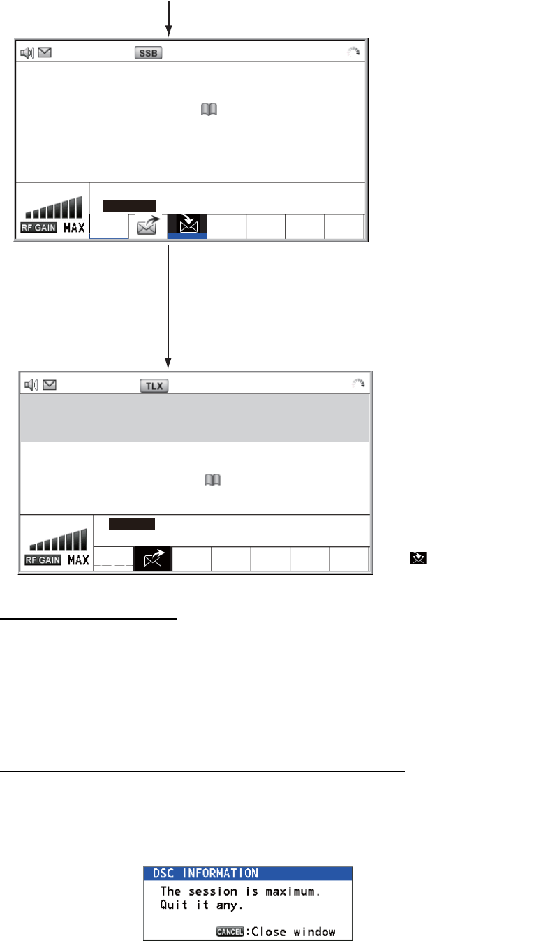
Processing when the number of session is maximum
A maximum of seven sessions can be displayed in the tab area. If a seventh session
starts, the following message appears on the screen. Press the CANCEL key to close
the message. Close a session to make space for the new session.
If the eighth session is for sending a distress alert, all sessions except that session
automatically close, and the session starts.
[SELECT AN ACK] ELAPSED TIME:
INDIVIDUAL MSG 00H01M12S
FROM :
123456789 CAPTAIN_2575
COMM MODE : TELEPHONE
COMM FREQ : TX 2170.0 /RX 2170.0 kHz
INFO PRINT HOLD QUIT
ACCEPT UNABLE PROPOSE
TX 2177.0/ RX 2177.00 kHz
RT
Only the screen for
the selected
session appears.
[WAIT FOR ACK]
INDIVIDUAL MSG ELAPSED TIME : 00H05M24S
TO : 987654321 CAPTAIN_5075
COMM MODE : TELEPHONE
COMM FREQ : TX 2170.0 / RX 2170.0 kHz
ACTIVE INFO PRINT QUIT
TX 2177.0/ RX 2177.00 kHz
RT
To finish this session, rotate the ENTER knob to
select [QUIT] then push the knob.
NO ACTIVE
The icon disappears.
(Continued from
previous page)
Note: When waiting for the ACK, that is, the
session is in progress, the confirmation message
appears. Rotate the ENTER knob to select [YES]
or [NO] then push the knob.
1. OPERATIONAL OVERVIEW
1-10
If the eighth session is for receiving DSC message, the lowest-priority session auto-
matically closes and the message appears.
2-1
2. SSB RADIOTELEPHONE
You can do SSB communications from any screen which displays the communication
frequency.
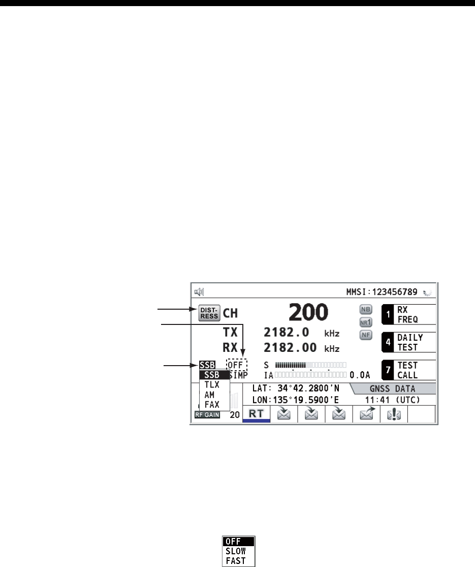
2.1 How to Select the Class of Emission
You can select the class of emission from among the following:
• [SSB]: Single Sideband
• [TLX]: Telex
• [AM]: AM (RX only)
• [FAX]: FAX (RX only. Connect a FAX to this equipment to print FAX messages.)
At the RT screen, select the class of emission as follows:
1. Rotate the ENTER knob to highlight the class of emission (default: [SSB]) then
push the knob. When you rotate the ENTER knob clockwise, the cursor moves
from [CH] downward.
2. Rotate the ENTER knob to select the class of emission desired then push the
knob. AGC is automatically turned on or off according to the class of emission.
3. You can change AGC as below.
1) Rotate the ENTER knob to select the AGC mode indication then push the
knob.
2) Rotate the ENTER knob to select [OFF], [SLOW] or [FAST] then push the
knob.
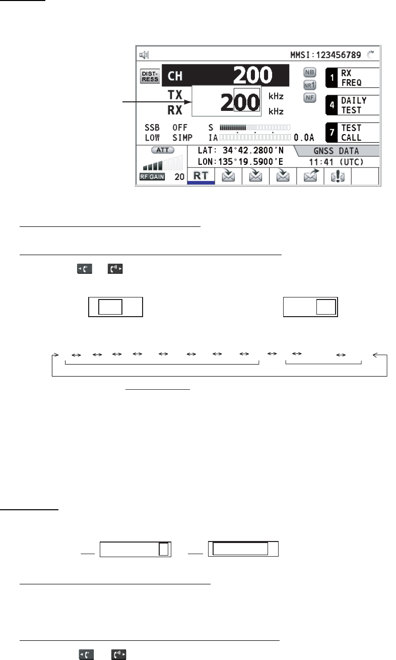
2.2 How to Select the Channel, Frequency
Select the channel or transmitting/receiving frequency to use for the SSB.
Note: To set the SSB radiotelephone to 2182 kHz/J3E, press the 2182 key.
• [SSB]: [FAST] • [TLX], [FAX]: [OFF] • [AM]: [SLOW]
Class of
emission
AGC mode
(Automatic Gain
Control)
This icon appears
when the frequency
is for distress.
2. SSB RADIOTELEPHONE
2-2
Channel
1. Rotate the ENTER knob to select [CH] on the RT screen then push the knob. You
can also show the channel setting window by pressing the RT/CH key.
2. A channel can be entered directly with the numeric keys, or by using the ENTER
knob. See below for details.
Enter channel with the numeric keys:
Use the numeric keys to enter channel then push the ENTER knob.
Select band and band channel with the ENTER knob:
1) Use the or key to place the cursor in the band or band channel position,
whichever you want to change.
2) Rotate the ENTER knob to set band or band channel desired.
3) Push the ENTER knob to close the setting window.
Frequency
1. Rotate the ENTER knob to select [TX] or [RX] then push the knob.
2. Enter frequency by one of the methods below.
Enter frequency with the numeric keys:
Use the numeric keys to enter frequency then push the ENTER knob. For exam-
ple, to enter 2161 kHz, key in 2, 1, 6, 1, 0. (Note: Keying in 2-1-6-1 sets 216.1
kHz.) Be sure to include zero for 100 Hz place.
Select frequency with the ENTER knob (for RX only):
1) Use the or key to change the range which the cursor covers.
2) Rotate the ENTER knob to set frequency desired.
3) Push the ENTER knob to close the setting window.
Note: When TX and RX frequencies are different, first enter TX then enter RX.
Channel setting
window
Cursor position for selection of band channel
2 0 0
Cursor position for selection of band
2 0 0
2 4 6 8 12 16 18 22 25 01 02----- 029
ITU band User band
Setting Range
ITU Band (SSB, TLX): 2/4/6/8/12/16/18/22/25
ITU Band (CW): 4/6/8/12/16/22/25
User Band: 01-029 (First zero is necessary)
ITU Channel (SSB): 00 - XX
ITU Channel (TLX): 000 - XXX
ITU Channel (CW): 001 - XXX
User Channel: 01 - 99
2182.0
TX RX
2182.00
2. SSB RADIOTELEPHONE
2-3
2.3 Transmission
After selecting the class of emission and frequency, you can transmit by pressing the
PTT switch on the handset.
2.3.1 Transmission procedure
Maximum transmission power is achieved only when the antenna impedance and
transmitter impedance match each other. Because the antenna impedance changes
with frequency, antenna impedance matching with the transmitter impedance is done
with the antenna coupler. The antenna coupler automatically tunes the transmitter to
a wide range of different antenna lengths. The available range is;
• Wire antenna 10 to 18 meters long (horizontal part)
• Whip antenna eight meters long (Horizontal feeder is two meters or longer.)
• Whip antenna 10 meters long
To initiate the tuning, do the following:
1. Press the PTT switch on the handset. Tuning is automatically adjusted at first
transmission after frequency is changed. For manual tuning, press the 0/TUNE
key on the RT screen. If tuning fails, the message "TUNE NG" appears and the
output power is automatically set to [LOW] (for FS-1575/2575) or [LOW2] (for FS-
5075).
2. Hold the handset close to your mouth, press the PTT switch and speak clearly.
Note: When tuning is initiated in the two control unit system, the screen of the idle con-
trol unit shows "OCCUPIED (CONTROLLER 1 (or 2))". In this case, only the
DISTRESS key is operative on the idle control unit.
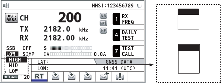
2.3.2 How to change transmission power
To minimize possible interference to other stations, reduce the transmission power.
This should be done when using the transceiver in a harbor, near the shore or close
to communication partner (other ship).
1. Rotate the ENTER knob to select [HIGH], [MID], [LOW] (for FS-1575/2575),
[LOW1] (for FS-5075) or [LOW2] (for FS-5075) (whichever is displayed), then
push the knob.
HIGH
MID
LOW1
LOW2
HIGH
MID
LOW
For FS-5075
For FS-1575/2575
135°19
.
5900
'
E
34°42
.
2800
'
N
2. SSB RADIOTELEPHONE
2-4
2. Rotate the ENTER knob to select the option desired then push the knob.
Note: The temperature of the power amplifier is monitored. When its temperature ris-
es above a certain temperature, output power is automatically reduced.
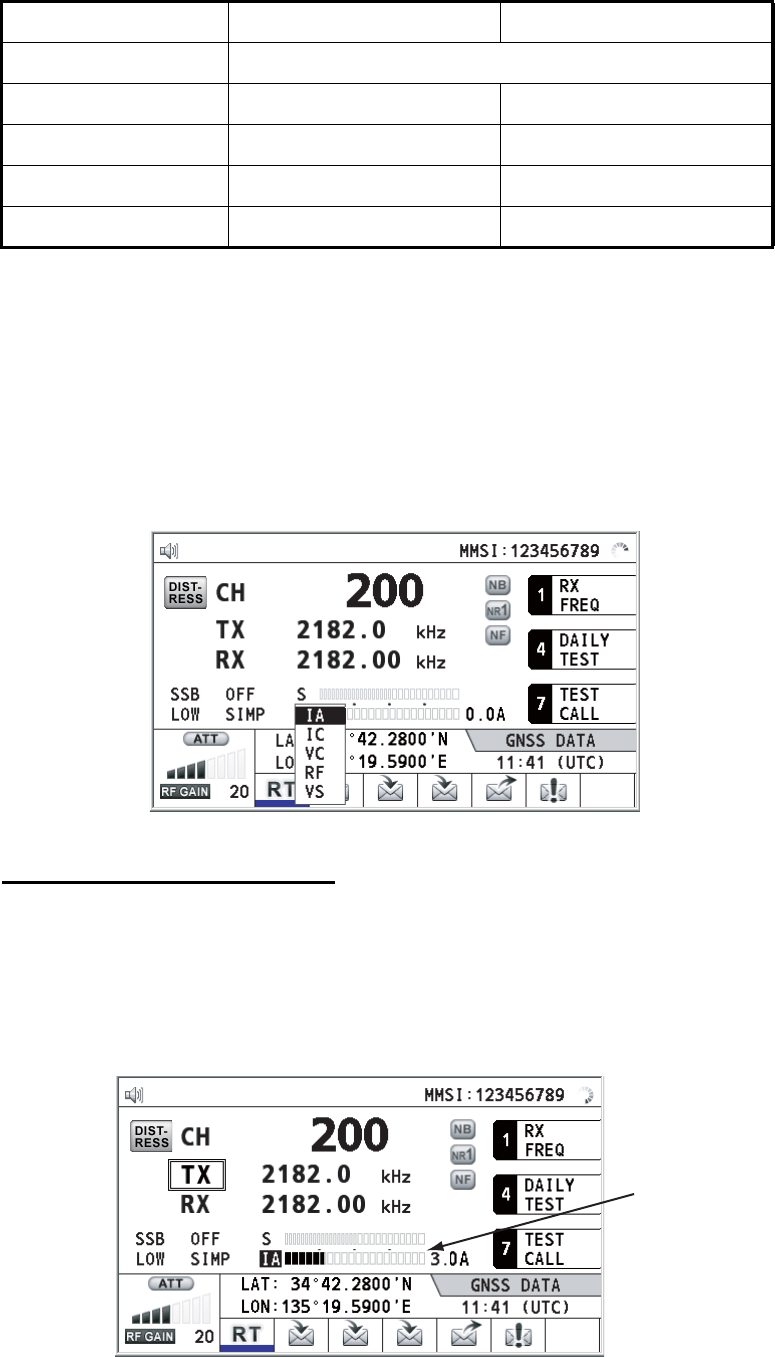
2.3.3 Condition of the transmitter
While transmitting, you can display [IA] (antenna current), [IC] (collector current), [VC]
(collector voltage), [RF] (RF output) or [VS] (source voltage) on the RT screen.
1. Rotate the ENTER knob to select [IA], [IC], [VC], [RF] or [VS] (whichever is dis-
played) then push the knob.
2. Rotate the ENTER knob to select the option desired then push the knob.
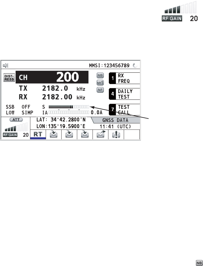
Check the transmission power
During transmission, the IA bar deflects according to the current being fed from the
antenna coupler to the antenna feeder. The unit of readout is amperes. The antenna
current varies with the effective antenna impedance. The reading differs by the fre-
quency and antenna length. The output power is proportional to the square of an an-
tenna current.
FS-1575/2575 FS-5075
[HIGH] No reducing
[MID] 125 Wpep 350 Wpep
[LOW] 90 Wpep -
[LOW1] - 200 Wpep
[LOW2] - 110 Wpep
Antenna
current
2. SSB RADIOTELEPHONE
2-5
2.4 Reception
Check if the class of emission and receiving frequency are set properly. If necessary,
set them again referring to sections 2.1 and 2.2.
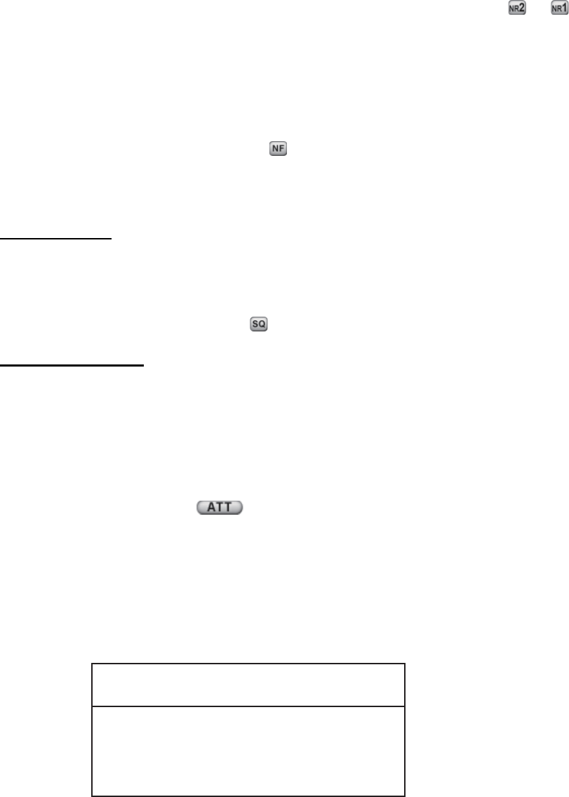
2.4.1 RF gain (sensitivity) adjustment
In normal use the sensitivity should be set for maximum. If the audio on the received
channel is unclear or interfered with other signals, adjust (usually reduce) sensitivity
to improve clarity.
Rotate the RF GAIN/PUSH TO ATT knob to adjust gain (sensitivity).
The setting value is displayed at the lower left-hand side of the
screen, with analog and digital indications.
2.4.2 S-meter
The S-meter shows relative signal strength coming into the receiver front end.
2.4.3 Receive AM broadcasting stations
1. If the RT screen is not displayed, press the RT/CH key to display the RT screen.
2. Rotate the ENTER knob to select the current class of emission then push the
knob.
3. Rotate the ENTER knob to select [AM] then push the knob (see section 2.1).
4. Rotate the ENTER knob to select [RX] then push the knob.
5. Enter RX frequency with the numeric keys then push the ENTER knob (see "Fre-
quency" in section 2.2).
2.4.4 Noise blanker
The noise blanker removes pulse noise. Press the 2/NB key on the RT screen to turn
the noise blanker on and off alternately. When the noise blanker function is active,
is displayed on the RT screen.
2.4.5 Noise reduction
The noise reduction circuit analyzes speech component and noise component, and
reduces only noise component. Press the 5/NR key on the RT screen. Each time you
press the 5/NR key, the effect of noise reduction changes in the sequence of ([NR2]
S-meter
2. SSB RADIOTELEPHONE
2-6
(High) → [NR1] (Low) → Off). When the noise reduction function is active, or
is displayed on the RT screen.
2.4.6 Notch filter
The notch filter removes mixed CW (continuous wave) or beat signal interference.
Press the 8/NF key on the RT screen to turn the notch filter on and off alternately.
When the notch filter function is active, is displayed on the RT screen.
2.4.7 Squelch
Squelch on/off
The squelch mutes the audio output in the absence of an incoming signal. Press the
3/SQ key on the RT screen to turn the squelch on and off alternately. When radio noise
is too jarring during stand-by condition, it can be muted by activating the squelch.
When the squelch function is active, is displayed on the RT screen.
Squelch frequency
To adjust the squelch frequency, see section 6.4.
2.4.8 Attenuator
The attenuator reduces total gain and prevents saturation. Push the RF GAIN/PUSH
TO ATT knob on the RT screen to turn the attenuator on and off alternately. When the
attenuator function is active, is displayed on the RT screen.
2.5 User Channels
The [USER CH] menu provides for registration of user TX and RX channels, where
permitted. For further details, contact your dealer. See section 6.2 for the procedure.
NOTICE
FURUNO will assume no responsibility
for the disturbance caused by the
unlawful or improper setting of user
channels.
3-1
3. DSC OVERVIEW
3.1 What is DSC?
DSC is an acronym meaning Digital Selective Calling. It is a digital distress and gen-
eral calling system in the MF and HF bands used by ships for transmitting distress
alerts and general calls and by coast stations for transmitting the associated acknowl-
edgements.
For DSC distress, safety and urgency callings in the MF and HF bands, the frequen-
cies are 2187.5, 4207.5, 6312.0, 8414.5, 12577.0, and 16804.5 kHz.
3.2 DSC Message
DSC calls are roughly divided in two groups: distress messages and general (safety,
urgency and routine) messages. Below are the types of DSC messages.
*SPECIAL MSG: To send these messages, set [SPECIAL MSG] to [ABLE]. See
section 6.18.
Call Description
DISTRESS ALERT Your ship sends distress message.
DISTRESS RELAY
AREA
Your ship relays distress call to all ships in a specific geographical area.
DISTRESS RELAY
INDIVIDUAL
Your ship relays distress call to a coast station.
MEDICAL MSG* Inform areas that your ship is carrying medical supplies.
NEUTRAL MSG* Inform areas that your ship is not a participant in armed conflict.
INDIVIDUAL MSG Call to a specific address.
PSTN MSG Call over Public Switched Telephone Network (PSTN).
TEST MSG Send test signal to a station to test your station's functionality.
GROUP MSG Call to a specific group.
AREA MSG Call to all ships in a specific geographical area.
POSITION MSG Your ship requests position of other ships.
POLLING MSG Confirm if your ship is within communicating range with other ships. (Re-
ceive and answer only)
Distress, Safety, Urgency DSC calls
Routine DSC Call
Option
Routine DSC Call
TRANSCEIVER
UNIT CONTROL UNIT
Distress, Safety, Urgency and Routine DSC Calls

3. DSC OVERVIEW
3-2
Contents of a DSC call
• Calling category
• Station ID (MMSI)
Your ship ID and sending station ID. Coast station ID begins with 00; Group ID be-
gins with 0.
• Priority
Distress: Grave and imminent danger and request immediate assistance.
Urgency: A calling station has a very urgent call to transmit concerning safety of
ship, aircraft or other vehicle or safety of person.
Safety: A station is about to transmit a call containing an important navigational or
meteorological warning.
Routine: General calling
• Communication mode
TELEPHONE: Telephone (J3E) by SSB radiotelephone
NBDP-ARQ*: Telex (J2B) mode ARQ via NBDP Terminal Unit
NBDP-FEC*: Telex (J2B) mode FEC via NBDP Terminal Unit
*: NBDP terminal unit is required.
• Communication frequency
Working frequency used to call by telephone or NBDP. The sending station may
have the receiving station (ship or coast station) assign the frequency to use.
• Position
Position can be automatically or manually set.
• DSC frequency
DSC frequency to use. If the call priority is SAFETY, URGENCY or DISTRESS, se-
lect a DSC distress frequency.
• End code
The end of a DSC call is indicated with "EOS" (acknowledgement, acknowledge-
ment required, no acknowledgement required).
3.3 Audio Alarms
When you receive a distress alert or general call addressed to your ship, the audio and
visual alarms are released. The audio alarm can be silenced with the CANCEL key.
Call category Call
DISTRESS DISTRESS ALERT, DISTRESS RELAY AREA, DISTRESS
RELAY INDIVIDUAL
GENERAL MEDICAL MSG, NEUTRAL MSG, INDIVIDUAL MSG, PSTN MSG,
TEST MSG, GROUP MSG, AREA MSG, POSITION MSG,
POLLING MSG
Alarm Frequency (interval)
Safety call received 750 Hz and 650 Hz (50 ms)
Routine call received 750 Hz and 650 Hz (50 ms)
While DISTRESS key is pressed for four
seconds
2000 Hz and 0 Hz (500 ms)
3. DSC OVERVIEW
3-3
3.4 Description of Call Screens
This section provides the information necessary for interpreting the receive and send
call screens.
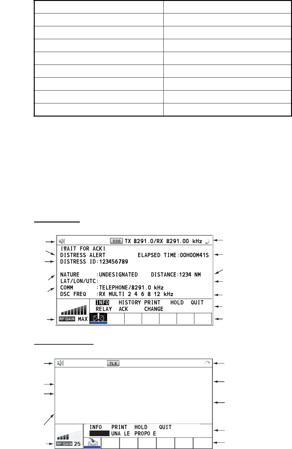
3.4.1 RX calls
Below are sample distress alert and individual RX call screens. The contents of other
types of RX calls are similar to that of the individual call.
Distress alert
Individual RX call
Distress alert sent 2200 Hz, continuous (2 seconds)
Own ship position not updated 2000 Hz (250 ms) and 0 Hz (500 ms)
Distress alert call received 2200 Hz and 1300 Hz (250 ms)
Distress relay call received 2200 Hz and 1300 Hz (250 ms)
Distress relay ack call received 2200 Hz (500 ms) and 1300 Hz (500 ms)
Distress ack call received 2200 Hz (500 ms) and 1300 Hz (500 ms)
Urgency call received 2200 Hz and 0 Hz (250 ms)
Urgency ack call received 2200 Hz and 0 Hz (500 ms)
Alarm Frequency (interval)
Working frequency
to use
Call type
Elapsed time since
distress alert received
ID No. (MMSI)
of ship in
distress
Communication
mode and
suggested
channel Available user options
Session in progress
RF gain
Speaker icon
DSC frequency
Position of ship
in distress
Nature of distress
Distance to ship
in distress
34°42.2800’N/135°19.5900’W/14:12
Working frequency
to use
Speaker icon
Elapsed time since
call received
ID No. (MMSI)
of ship
sending this
message
Communication
frequency
RF gain
Available user options
Communication mode
Session in progress
Call type
[SELECT AN ACK]
INDIVIDUAL MSG
ELAPSED TIME:
00
H
00
M
16
S
FROM :
COMM MODE
:
COMM FREQ
:
123456789
TELEPHONE
TX 2170.0/RX
2170.0 kHz
S
ACCEPT B
TX 2177.0
/
RX 2177.00kHz
3. DSC OVERVIEW
3-4
The marks "*", "-" appear on the DSC receiving screen in the following conditions:
• "*" indicates a corrupt character in received data.
• "-" indicates missing digits after decimal point when receiving position data with no
info for expansion (expansion: digits after decimal point).
Examples:
1) When receiving position data without expansion, the indication is
"LAT: 12°34’N".
2) When receiving position data with expansion, the indication is
"LAT: 12°34,5678’N".
3) When receiving position data with no info for expansion, the indication is
"LAT: 12°34,----’N".
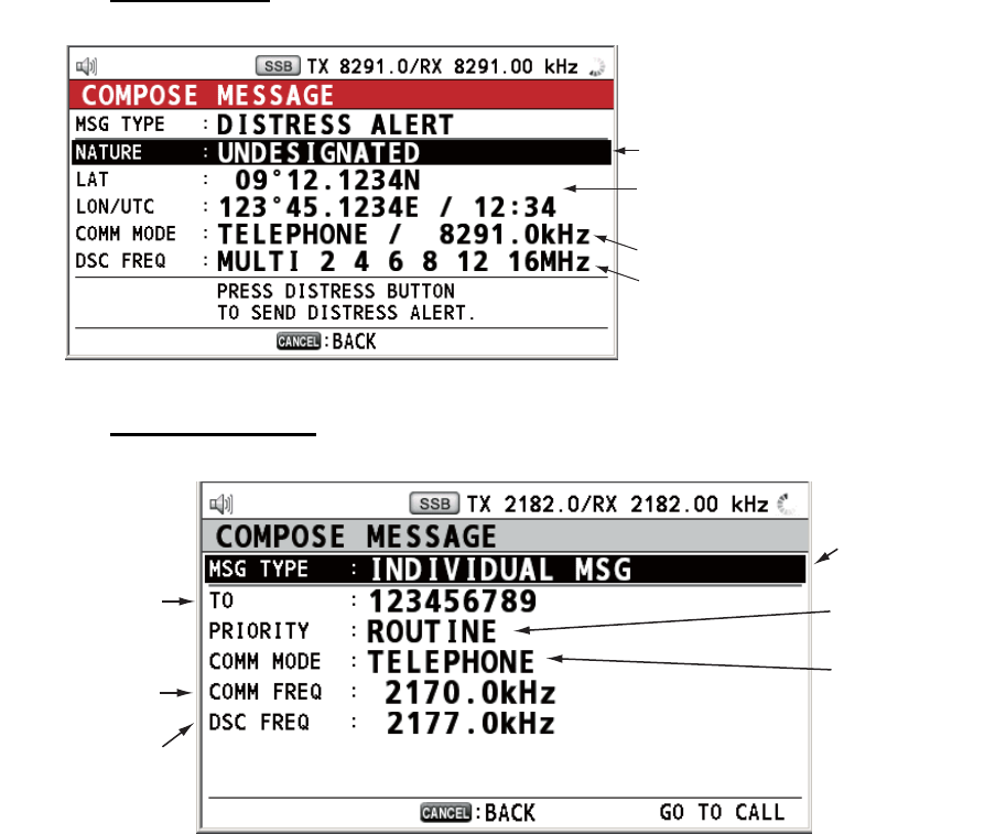
3.4.2 TX calls
Below are sample distress alert and individual TX call screens. The contents of other
types of TX calls are similar to that of the individual call.
Distress alert
Individual TX call
Nature of Distress
Position of ship in distress (your
ship) and time of distress
Communication mode
DSC frequency to send distress call
Message type
(Individual)
ID No. of station
where message
is to be sent
Priority (Routine,
Safety, Urgency)
Communication
mode
(Telephone,
NBDP-ARQ,
NBDP-FEC)
Communication
frequency
DSC frequency
4-1
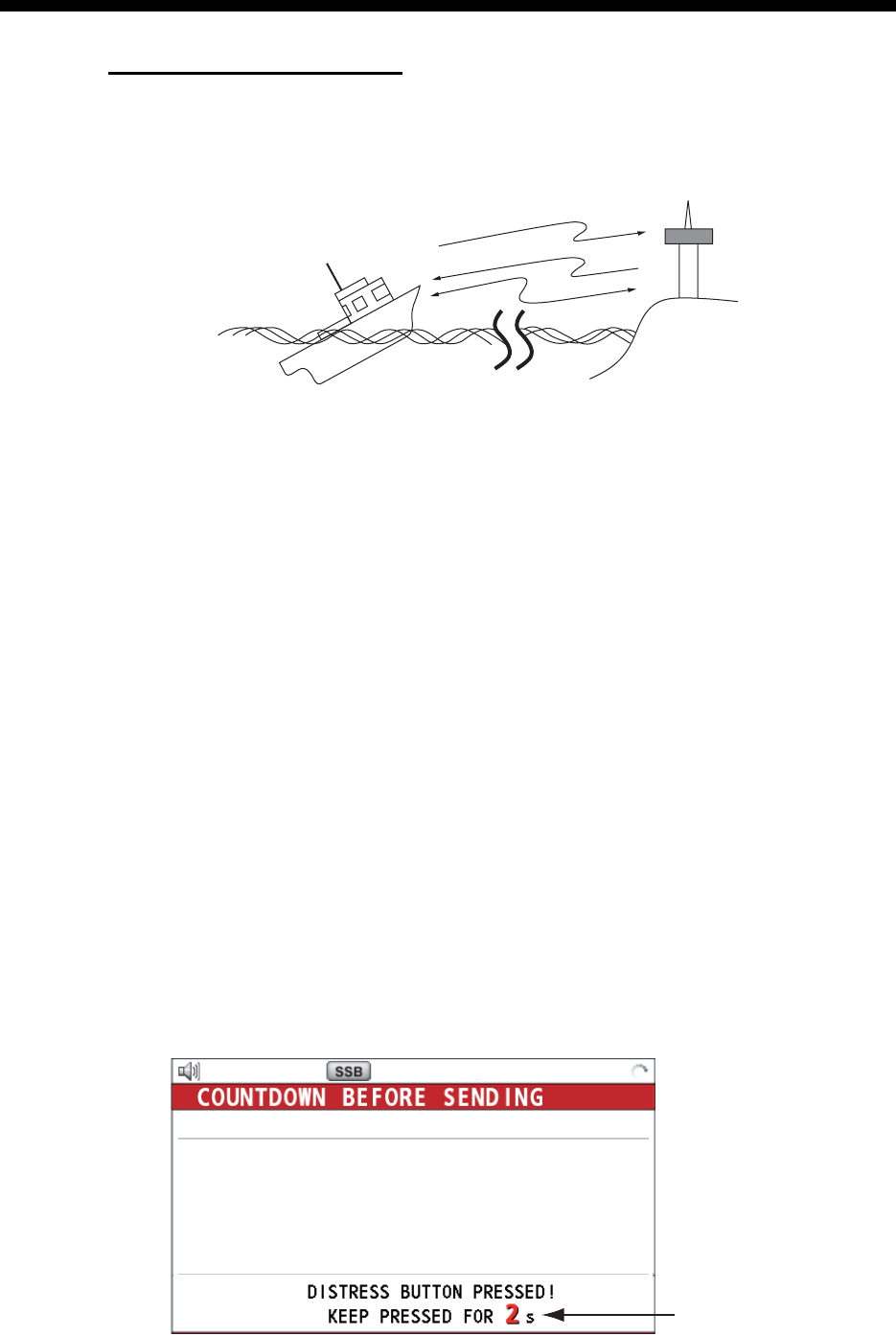
4. DSC DISTRESS OPERATIONS
Distress operation overview
1. Press the DISTRESS key.
2. Wait for the distress alert acknowledgement.
3. Communicate with the coast station.
4.1 How to Send Distress Alert
GMDSS ships carry a DSC terminal with which to transmit the distress alert in the
event of a life-endangering situation. A coast station receives the distress alert and
sends the distress alert acknowledge call to the ship in distress. Then, voice or telex
communication between the ship in distress and coast station begins. Transmission
of the distress alert and receiving of the distress alert acknowledgement are complete-
ly automatic - simply press the DISTRESS key to initiate the sequence.
There are three types of distress alerts; MULTI, SINGLE, AUTO. MULTI is used nor-
mally. To use another method, see step 10 in paragraph 4.1.2.
Note: After sending the distress alert, no control unit has priority.
4.1.1 How to send distress alert by DISTRESS key with distress in-
formation not edited
1. Open the DISTRESS key cover then press the DISTRESS key for four seconds.
The audio alarm sounds while pressing the key, and the key flashes in red. The
countdown message appears on the screen while pressing the DISTRESS key
(3S → 2S → 1S → 0S).
(3)
(2)
(1)
Ship in distress
(Your ship)
(1) Ship in distress sends Distress Alert.
(2) Coast station sends distress acknowledgement (DIST ACK).
(3) Voice or telex communication between ship in distress and coast station.
Coast
station
Countdown message
TX 2182 . 0 / RX 2182 . 00 kHz
MSG TYPE : DISTRESS ALERT
NATURE : UNDESIGNATED
LAT : 09
°
12.1234’ N
LON/UTC : 123
°
45.1234’ E /12 : 34
COMM MODE
: TELEPHONE
DSC FREQ : MULTI 2 4 6 8 12 16MHz
4. DSC DISTRESS OPERATIONS
4-2
When the countdown shows 0S, the distress alert is sent. The audio alarm sounds
for two seconds and the message "Sending DISTRESS ALERT." appears. The
screen shows the contents of the distress alert call. The DISTRESS key lights in
red and only the icon for DISTRESS transmission ( ) is displayed in the tab ar-
ea.
After the distress alert has been sent, the screen changes as below. Wait to re-
ceive the distress acknowledge call from a coast station. The elapsed time since
transmission is displayed. At this time, the icons for other DSC received messag-
es except the distress alert acknowledge call are not displayed. You can only con-
firm them in the log.
Note: If you do not receive the distress alert acknowledge call, the equipment au-
tomatically re-transmits the distress alert after 3 min 30 seconds to 4 min 30 sec-
onds. Then awaits the distress alert acknowledge call. This is repeated until the
distress alert is acknowledged.
You can temporarily stop the countdown for next retransmission by selecting
[PAUSE] in the user options area. [PAUSE] indication changes to [START] and
[PAUSE] is displayed instead of the countdown indication. To restart, select
[START]. The countdown restarts and [START] indication in the user options area
changes to [PAUSE].
Also, you can re-send the distress alert manually by pressing the DISTRESS key
for four seconds.
When the distress acknowledge call is received, the audio alarm sounds, the LED
flashes in red, and the icon for DISTRESS transmission ( ) appears. The
screen changes as below.
Elapsed time
since distress
alert transmission
User options area
PRINT
TX 2182 . 0 / RX 2182 . 00 kHz
09° 12.1234’ N/ 123° 45.1234’ E / 12 : 34
Tab area
CHANGE
[ WAIT FOR ACK ]
2, 4, 6, 8, 12, 16
MH
z
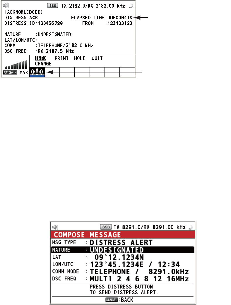
4. DSC DISTRESS OPERATIONS
4-3
2. Press the CANCEL key to silence the audio alarm. Then, the LED stops flashing,
and the pop-up message disappears.
3. Communicate with the coast station via radiotelephone, following the instructions
below. If the distress alert was sent using the MULTI mode, the radiotelephone
automatically sets the working frequency on which the distress acknowledge call
is first received.
a) Say “MAYDAY” three times.
b) Say “This is ...” name of your ship and call sign three times.
c) Give nature of distress and assistance needed.
d) Give description of your ship (type, color, number of persons onboard, etc.).
4.1.2 How to send distress alert by DISTRESS key with distress in-
formation edited
If you have a time to prepare the distress information, send the distress alert as fol-
lows:
1. Press the DISTRESS MSG key to display the following screen.
2. With [NATURE] selected, push the ENTER knob.
3. Rotate the ENTER knob to select nature of distress, among the following 11 se-
lections, then push the knob.
• UNDESIGNATED • FIRE • FLOODING
• COLLISION • GROUNDING • LISTING
• SINKING • DISABLED&ADR(IFT) • ABANDONING
• PIRACY • MAN OVERBOARD
Count up the elapsed time
after receiving distress
acknowledge call.
Icon for DISTRESS transmitting
09
°
12.1234’ N/ 123
°
45.1234’ E / 12 : 34
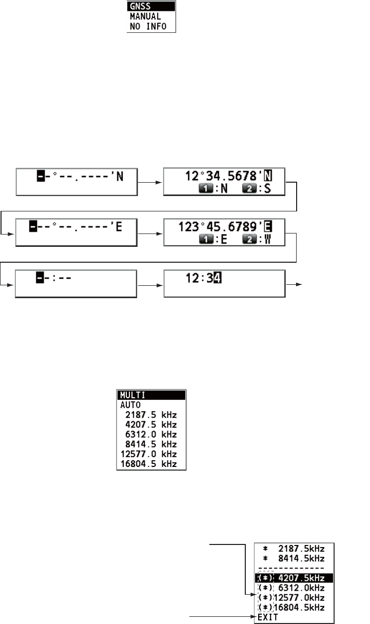
4. DSC DISTRESS OPERATIONS
4-4
4. With [LAT] and [LON/UTC] selected, push the ENTER knob.
[GNSS]: The position information from GNSS is automatically shown.
[MANUAL]: Input your position manually.
[NO INFO]: No information.
5. Rotate the ENTER knob to select [GNSS], [MANUAL] or [NO INFO] then push the
knob. For [MANUAL], go to step 6. For others, go to step 7.
6. Use the numeric keys to enter latitude, longitude and UTC time. (If necessary,
switch coordinates: 1 key to switch to North (East for longitude); 2 key to switch to
South (West for longitude).) Push the ENTER knob.
7. With [COMM MODE] selected, push the ENTER knob.
8. Rotate the ENTER knob to select [TELEPHONE] or [NBDP-FEC] then push the
knob.
9. With [DSC FREQ] selected, push the ENTER knob.
10. Rotate the ENTER knob to select the DSC frequency desired then push the knob.
[MULTI]: Transmit the distress alert on three to six frequencies (in numerical or-
der), which you can select among 2 MHz, 4 MHz, 6 MHz, 8 MHz, 12 MHz and 16
MHz. 2 MHz and 8 MHz are automatically selected and cannot be excluded.
[SINGLE]: You can transmit on the distress frequency of your selection. Select
one frequency among 2 MHz, 4 MHz, 6 MHz, 8 MHz, 12 MHz and 16 MHz.
[AUTO]: Transmit the distress alert on 2 MHz at first (40 to 60 seconds). If the dis-
tress alert is not acknowledged, transmission occurs in this sequence:
2nd: 8 MHz, 3rd: 16 MHz, 4th: 4 MHz, 5th: 12 MHz and 6th: 6 MHz
Latitude setting window
Longitude setting window
Push the
ENTER knob.
Push the
ENTER knob.
UTC setting window
Push the
ENTER knob.
Rotate the ENTER knob to select the
desired frequency then push the
knob. Each push of the ENTER knob
displays (selected) or removes
(deselected) the asterisk.
A
fter setting, rotate the ENTER knob to
select [EXIT] then push the knob.
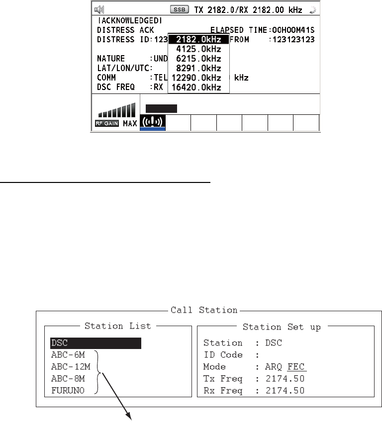
4. DSC DISTRESS OPERATIONS
4-5
11. Press the DISTRESS key for four seconds to send the distress alert. The audio
alarm sounds while pressing the key, and the key flashes in red. The countdown
message appears on the screen while pressing the DISTRESS key (3S → 2S →
1S → 0S) (refer to the illustration at step 1 in paragraph 4.1.1.). When the count-
down shows 0S, the distress alert is sent. The audio alarm sounds for two sec-
onds and the message "Sending DISTRESS ALERT." appears.
12. When the distress acknowledge call is received, use the telephone or telex to
communicate with the coast station. For NBDP, follow the procedure in “Commu-
nicating by NBDP terminal unit” on this page. For telephone, follow step 3 on
paragraph 4.1.1. If you selected [MULTI] at step 10, you can communicate via
telephone, on the communication frequency which the distress acknowledge call
is received. If it is necessary to change the frequency, do the following:
1) Rotate the ENTER knob to select [CHANGE] in the user options area then
push the knob.
2) Rotate the ENTER knob to select the appropriate frequency then push the
knob.
Communication by NBDP terminal unit
The message "STATION ENTRY COMPLETED FROM DSC. Press any key to es-
cape." appears on the NBDP's screen.
1. Press any key on the NBDP terminal unit to erase the message.
2. Press the function key F3 on the keyboard of the NBDP terminal unit to open the
[Operate] menu.
3. Select [Call Station] then press the ENTER knob.
4. With [DSC] selected, press the Enter key to connect the communication line.
"Connect" appears in reverse video.
5. Type and transmit your message, giving the following information:
• Ship's name and call sign
09
°
12’ N/ 123
°
45’ E / 12 : 34
INFO PRINT HOLD QUIT
CHANGE
For IB-585, these items are not displayed
when sending the distress alert.
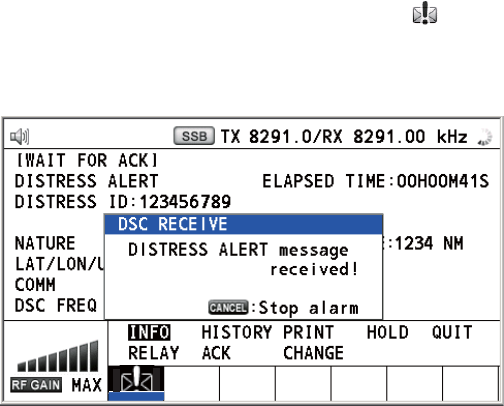
4. DSC DISTRESS OPERATIONS
4-6
• Nature of distress and assistance needed
• Description of your ship
6. Press the function key F10 to disconnect the line.
For NBDP details, see chapters 7 through 10.
4.2 How to Receive a Distress Alert
When you receive a distress alert from a ship in distress, the audio alarm sounds and
the LED flashes in red. The icon for DISTRESS receiving ( ) appears in the tab area
and the pop-up message "DISTRESS ALERT message received! [CANCEL]: Stop
alarm" appears on the screen.
Press the CANCEL key to silence the audio alarm. Wait for the distress acknowledge
call from a coast station. If you do not receive the distress acknowledge call from a
coast station, which usually takes about five minutes from the time of receiving a dis-
tress alert, follow the flow charts in this section to determine your action.
Note: An asterisk (*) appearing in a distress alert message indicates an error at the
asterisk’s location.
4.2.1 Distress alert received on MF band
Do the following:
• Continue watching on 2182 kHz. Wait for coast station to acknowledge the distress
call. Watch until “SEELONCE FINI” is announced.
• If multiple DSC distress alerts are received from the same ship in distress and it is
near your ship, communicate with RCC or coast station and send distress acknowl-
edge call to the ship in distress under the direction of RCC or coast station.
• Watch on the distress frequency.
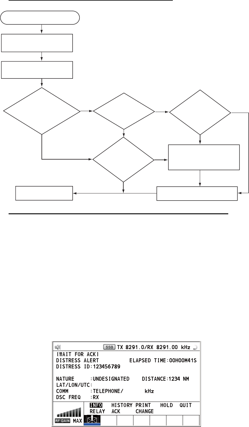
4. DSC DISTRESS OPERATIONS
4-7
Action for ship receiving distress alert on MF band
Send the distress acknowledge call to ship in distress (on MF band)
Note: You must wait at least five minutes before you can acknowledge a distress alert,
to allow time for a coast station to transmit the distress acknowledge.
Transmit the distress acknowledge call to the ship in distress only when you do not
receive it from a coast station and you are able to aid the ship in distress. First, contact
the ship in distress over radiotelephone.
When you receive a distress alert from a ship in distress, the audio alarm sounds and
the LED flashes in red. The icon for DISTRESS receiving appears in the tab area and
the pop-up message "DISTRESS ALERT message received! [CANCEL]: Stop alarm"
appears on the screen.
To terminate transmission of the distress alert, send acknowledge call as follows.
1. Press the CANCEL key to silence the audio alarm and stop the flashing of the
LED.
DSC distress alert received.
Press the CANCEL key
to silence alarm.
Listen on 2182 kHz
for 5 minutes.
Did you receive
acknowledge from
CS and/or RCC?
No No No
Yes
Yes Yes
Yes
No
Is distress traffic
in progress?
Is the DSC
distress call
continuing?
Is your ship
able to aid
ship in
distress?
Acknowledge the alert by
radiotelephone to the ship
in distress on 2182 kHz.
Inform CS and/or RCC.
Enter details in log.
CS = Coast Station
RCC = Rescue Coordination Center
09°
12.1234’ N/ 123°
45.1234’ W / 12 : 34
2182 . 0
2187 . 5 kHz
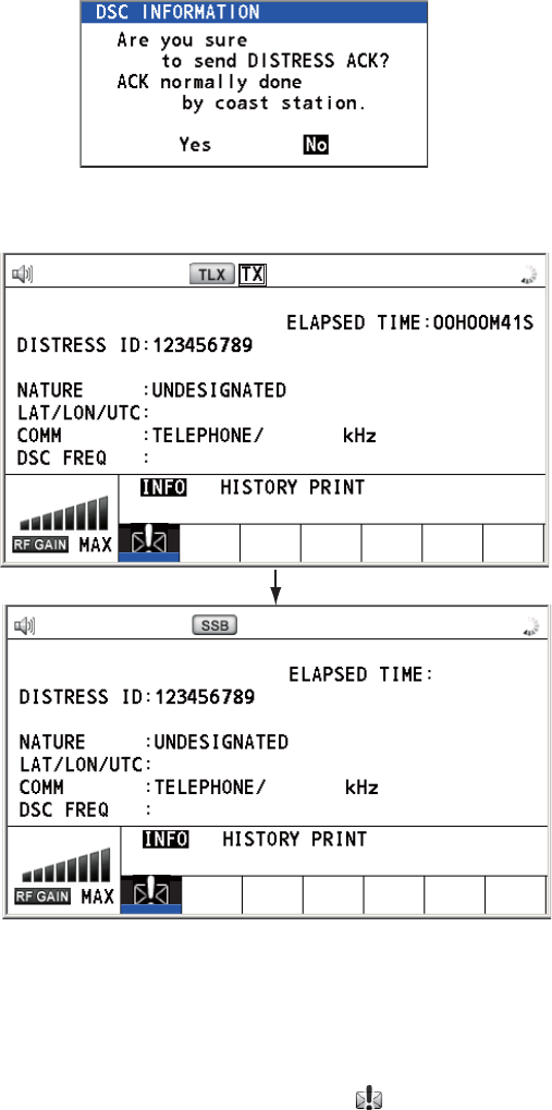
4. DSC DISTRESS OPERATIONS
4-8
2. If you do not receive the distress acknowledge call from a coast station and you
have received the distress alert more than twice, contact the ship in distress over
radiotelephone.
3. Rotate the ENTER knob to select [ACK] in the user options area then push the
knob. The following message appears on the screen.
4. Rotate the ENTER knob to select [Yes] then push the knob to transmit the distress
acknowledge call to the ship in distress. The screen changes as below.
Note: You can not edit the message for the distress acknowledge call.
4.2.2 Distress alert received on HF band
If you receive a distress alert on the HF band, the audio alarm sounds and the LED
flashes in red. The icon for DISTRESS receiving ( ) appears in the tab area and the
pop-up message "DISTRESS ALERT message received! [CANCEL]: Stop alarm" ap-
pears on the screen. Press the CANCEL key to silence the audio alarm and stop the
flashing of the LED. The screen for receiving the distress alert appears. Wait for the
distress acknowledge call from a coast station. If you do not receive the distress ac-
knowledge call from a coast station, which usually takes about five minutes from the
time of receiving a distress alert, follow the flow chart in this section to determine your
action.
• Watch on the distress frequency.
FROM
: 987654321
[ SENDING ]
09
°
12.1234’ N/ 123
°
45.1234’ W / 12 : 34
FROM
: 987654321
[ SENDING ]
09
°
12.1234’ N/ 123
°
45.1234’ W / 12 : 34
[ACKNOWLEDGED]
DI ST
R
ESS ACK
00
H
0
1M1
8
S
HOLD QUIT
RELAY ACK CHANGE
DI ST
R
ESS ACK
2187.5
/
RX 2187.50 kHz
2182.0
TX 2187.5 kHz
TX 2182.0
/
RX 2182.00 kHz
2182.0
TX 2187.5 kHz