Furuno USA 9ZWRTR065 MARINE RADAR User Manual OPERATORS MANUAL
Furuno USA Inc MARINE RADAR OPERATORS MANUAL
UserManual.wiki
>
Furuno USA
>
9ZWRTR065 User Manual
OPERATORS MANUAL
Navigation menu
Upload a User Manual
Namespaces
Wiki Guide
HTML
PDF
Info
Views
User Manual
Discussion / Help
Navigation
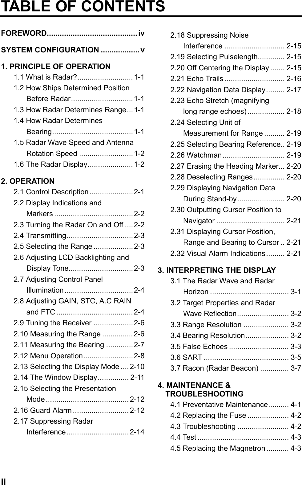

![2-22.2 Display Indications and Markers TRAIL15SG ( IN )FTC1ESIR0.5RangeRange ring intervalEcho trail, AUTO tuningEcho trail elapsed time,echo trail time, tuning indicatorGuard zoneFTC(rain clutter suppressor)Echo stretchInterference rejectorEBLRange ringsCursorHeading markerGuard zoneareaVRM1.5NMHDG 326.8˚SPPulsewidthHeading (requiresheading data)CU OFFCENTEROff center0:00VRMrange EBLbearing Cursorrange Cursorbearing}Range and bearing to cursor or cursor position in latitude and longitude may be displayed by pressing the [HM OFF] key.Presentation mode VRM EBL + CURSOR 0.675NM 232.5˚R 0.681NM 308.7˚R AUTOFigure 2-2 Display indications2.3 Turning the Radar On andOffPress the [POWER] key to turn the radaron or off. The control panel lights and atimer displays the time remaining for warmup of the magnetron (the device whichproduces radar pulses), counting downfrom 1:30.Note: When the power is reapplied within acertain amount of time and circuitsremain charged, the warmup processis skipped—you can transmit withoutone and a half minutes st-by time.The radar antenna emits high frequency radio radiation which can be harmful, particularly to your eyes. Never look directly at the antenna from a distance of less than three feet when the radar is in operation. Always make sure no one is near the antenna before turning on the radar.WARNING!](https://usermanual.wiki/Furuno-USA/9ZWRTR065/User-Guide-107590-Page-11.png)
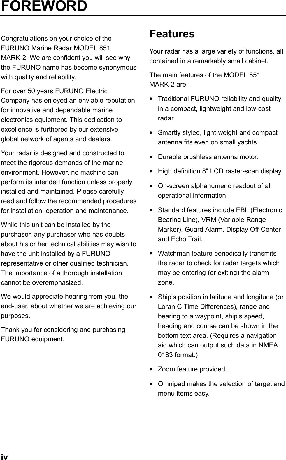
![2-3Note: When the heading signal is lost, theHDG readout at the top of the screenshows ***.*. This warning stays onwhen the heading signal is restoredto warn the operator that the readoutmay be unreliable. After confirmingthe heading readout (if necessary,adjust it), the warning may be erasedby pressing the [DISP MODE] key.2.4 TransmittingAfter the power is turned on and themagnetron has warmed up, ST-BY (Stand-By) appears at the screen center. Thismeans the radar is now fully operational. Instand-by the radar is available for use atanytime—but no radar waves are beingtransmitted.Press the [ST-BY TX] key to transmit.When transmitting, any echoes reflectedfrom targets appear on the display. Thisradar displays echoes in four tones of grayaccording to echo strength.When you won’t be using the radar for anextended period but want to keep it in astate of readiness, press the [ST-BY TX]key to set the radar in stand-by.2.5 Selecting the RangeThe range selected automaticallydetermines the range ring interval, thenumber of range rings, pulselength andpulse repetition rate, for optimal detectioncapability in short to long ranges.ProcedurePress the [– RANGE +] key. The range andrange ring interval appear at the top leftcorner on the display.Tips for selecting the range•When navigating in or around crowdedharbors, select a short range to watchfor possible collision situations.•If you select a lower range while onopen water, increase the rangeoccasionally to watch for vessels thatmay be heading your way.2.6 Adjusting LCDBacklighting and DisplayToneThe [BRILL] key adjusts the LCDbacklighting in eight levels, including off.The [TONE] key adjusts the tone (contrast)of the display in 32 levels, including off.Procedure1. Press the [BRILL] key (or [TONE] key).The display shown in Figure 2-3appears.BRILLDOWNBRILLUPTONEDOWN19 7 <MENU> TO EXITItem selectedfor adjustmentTonesettingTONEUPLCD brilliancesettingFigure 2-3 Display for adjustment ofbrilliance and tone2. Press the [BRILL] key (or [TONE] key)to set level. For fine adjustment, pressomnipad at 12 o'clock/6 o'clock forbrilliance and 3 o'clock/9 o'clock fortone.](https://usermanual.wiki/Furuno-USA/9ZWRTR065/User-Guide-107590-Page-12.png)
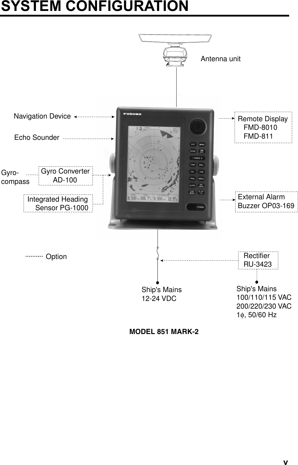
![2-42.7 Adjusting Control PanelIlluminationProcedure1. Press the [MENU] key.2. Press the omnipad at 6 o’clock toselect Backlight/Brilliance and pressthe [ENT] key.3. Press the omnipad at 6 o’clock toselect Panel.4. Press the omnipad at 3 o’clock/9o’clock to select illumination level; 4 isthe highest.5. Press the [ENT] key followed by the[MENU] key.2.8 Adjusting GAIN, STC, A.CRAIN and FTCGeneral procedureThe [ECHO] key enables adjustment of theGAIN, STC, A.C RAIN and FTC.1. Press the [ECHO] key. The followingdisplay appears.AUTO MAN AUTO 1 2 301MAN GAIN STC ◆◆[[0001201ECHO KEYTO EXITCurrent levelItem selectedfor adjustmentSelect auto ormanual bypressing the omnipad at 6 o'clock or 12 o'clock and pressing [ENT]key.Select auto or manual by pressing the omnipad at 6 o'clock or 12 o'clock and pressing [ENT] key.FTCA.C RAINSelect item/optionby pressing appropriateomnipad arrow.Figure 2-4 Display for adjustment of GAIN,STC, A.C RAIN and FTC2. Press the omnipad at 6 o’clock/12o’clock to select item to adjust. Currentselection is circumscribed by dashedrectangle.3. Press the [ENT] key.4. Press the omnipad at 3 o’clock/9o’clock to set level.5. Press the [ECHO] key to finish.How to adjust the GAIN (sensitivity)The GAIN works in precisely the samemanner as the volume control of abroadcast receiver, amplifying the signalsreceived.You can adjust the GAIN automatically ormanually. If you select AUTO, the GAINautomatically adjusted. The range of theGAIN adjustment is from 1 to 3; 3 is thehighest. For manual adjustment, adjust thesensitivity on the highest range—thebackground noise is clearer on that range.The range of GAIN adjustment is from 01to 41. The proper setting is such that thebackground noise is just visible on thescreen. If you set up for too little GAIN,weak echoes may be missed.On the contrary excessive GAIN yields toomuch background noise; strong targetsmay be missed because of the poorcontrast between desired echoes and thebackground noise on the display.](https://usermanual.wiki/Furuno-USA/9ZWRTR065/User-Guide-107590-Page-13.png)
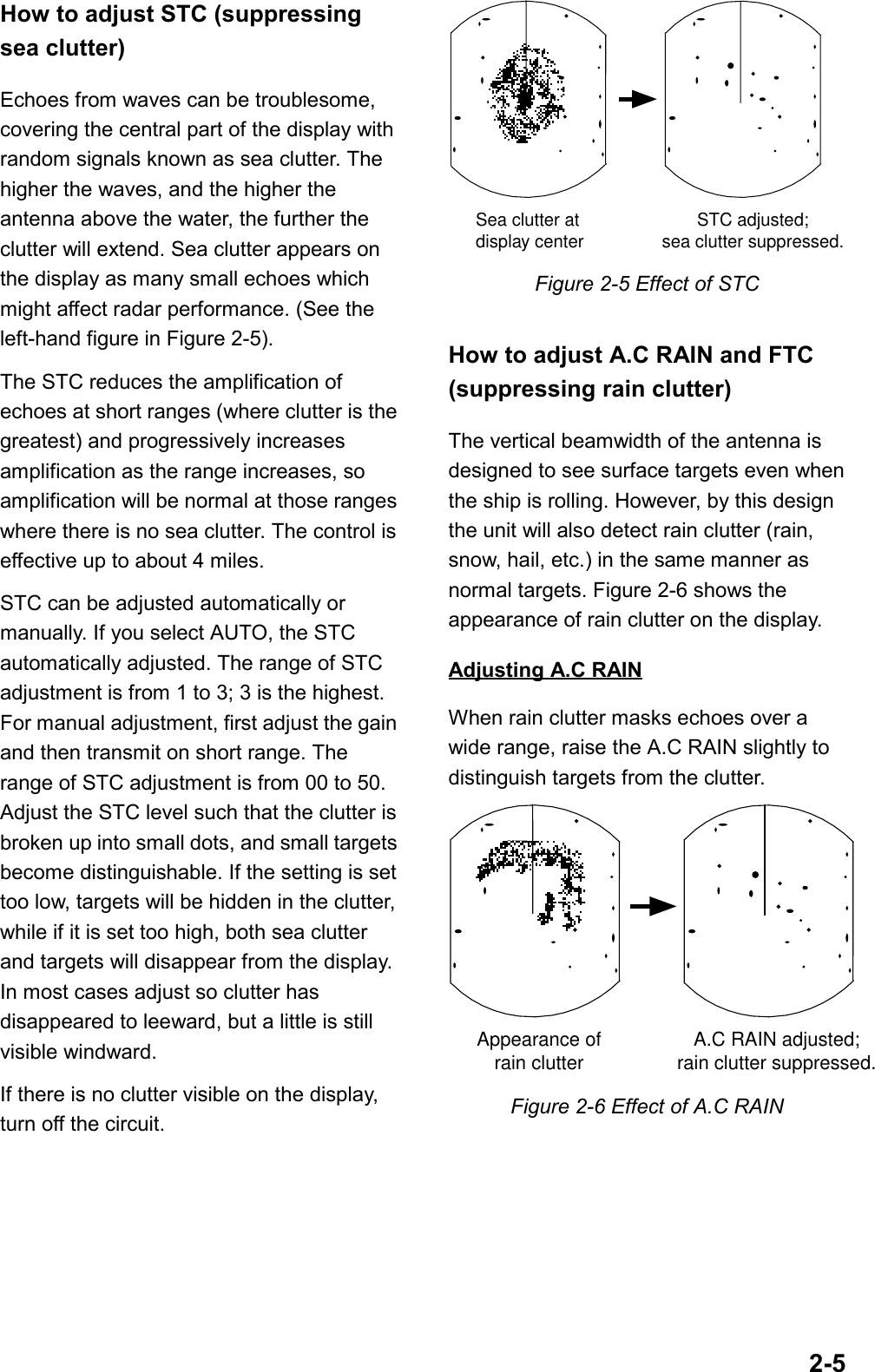
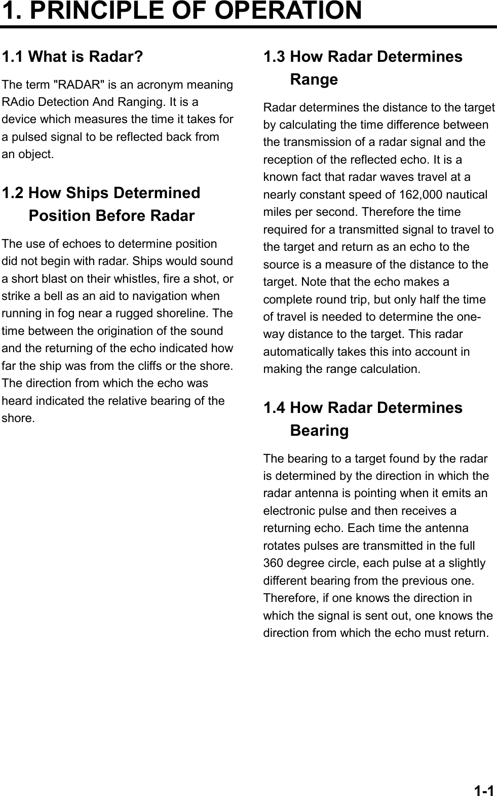
![2-6Adjusting FTCTo suppress rain clutter from heavy stormsor scattered rain clutter, adjust the FTCamong 0, 1 and 2 (0 is off). The FTC circuitsplits up these unwanted echoes into aspeckled pattern, making recognition ofsolid targets easier. FTC and selected levelappear at the top right-hand corner of thedisplay when the circuit is turned on.Note: In addition to reducing clutter, theFTC can be used in fine weather toclarify the picture when navigating inconfined waters. However, with thecircuit activated the receiver is lesssensitive. Therefore, turn off thecircuit when its function is notrequired.2.9 Tuning the ReceiverThe receiver can be tuned automatically ormanually. For automatic tuning the receiveris tuned each time you switch from stand-by to transmit. For manual tuning, thereceiver is properly tuned when the longesttuning indicator appears. (However, thelength of the indicator changes with thenumber of radar echoes, range and otherfactors.) 1.5NM 0.5 AUTOTuningindicatorFigure 2-7 Tuning indicatorManual tuningThe default tuning method is automatic. Toswitch to manual tuning;1. Press the [MENU] key to open themenu.2. Press the omnipad at 6 o’clock toselect Tuning.3. Press the omnipad at 3 o’clock toselect MANUAL.4. Press the [ENT] key followed by the[MENU] key.How to tune manuallyWhile pressing and holding down the [HMOFF] key, press the 9 o'clock or 3 o'clockposition on the omnipad to tune. Tune toshow the longest tuning indicator.2.10 Measuring the RangeYou can measure the range to a targetthree ways: by the range rings, by thecursor, and by the VRM (Variable RangeMarker).By range ringsPress the [RINGS] key to display the rangerings. Count the number of rings betweenthe center of the display and the target.Check the range ring interval (at the top leftcorner) and judge the distance of the echofrom the inner edge of the nearest ring.By cursorOperate the omnipad to place the cursorintersection on the inside edge of the targetecho. The range to the target, as well asthe bearing, appears at the bottom of thedisplay.](https://usermanual.wiki/Furuno-USA/9ZWRTR065/User-Guide-107590-Page-15.png)
![2-7By VRM1. Press the [VRM] key to display theVRM.2. Press the omnipad to place the VRMon the inside edge of the target.3. Check the VRM readout at the bottomleft-hand corner of the display to findthe range to the target.Note: The VRM is automatically anchoredif the omnipad is not operated withinabout 10 seconds.To erase the VRM, press and hold downthe [VRM] key for about two seconds. 1.5NM 0.5VRMrangeVRMTarget VRM EBL + CURSOR 0.675NM 220.9¡R 0.675NM 308.7˚RFigure 2-8 Measuring range by the VRM2.11 Measuring the BearingThere are two ways to measure the bearingto a target: by the cursor, and by the EBL(Electronic Bearing Line).By cursorOperate the omnipad to bisect the targetwith the cursor intersection. The bearing tothe target appears at the bottom right-handcorner of the display.By EBL1. Press the [EBL] key to display the EBL.2. Press the omnipad to bisect the targetwith the EBL.3. Check the EBL readout at the bottomleft-hand corner of the display to findthe bearing to the target.Note: The EBL is automatically anchored ifthe omnipad is not operated withinabout 10 seconds.To erase the EBL, press and hold downthe [EBL] key for about two seconds. 1.5NM 0.5EBLTargetEBLbearing VRM EBL + CURSOR 0.675 NM 300.1˚R 0.675NM 300.1˚R Figure 2-9 Measuring bearing by the EBL](https://usermanual.wiki/Furuno-USA/9ZWRTR065/User-Guide-107590-Page-16.png)
![2-8Tips for measuring the bearing•Bearing measurements of smallertargets are more accurate; the center oflarger target echoes is not as easilyidentified.•Bearings of stationary or slower movingtargets are more accurate than bearingsof faster moving targets.•To minimize bearing errors keep echoesin the outer half of the picture bychanging the range scale; angulardifference becomes difficult to resolveas a target approaches the center of thedisplay.Target on Collision course with your vessel?You can determine if a target might be on a collision course with your vessel by placing the EBL on the target. If it tracks along the EBL as it approaches the screen center it may be on a collision course with your vessel.2.12 Menu OperationThe menu, consisting of six sub menus,mostly contains less-often used functionswhich once preset do not require regularadjustment. To open or close the menu,press the [MENU] key. You can selectitems and options on the menu with theomnipad.Basic menu operation1. Press the [MENU] key to open the mainmenu.● MAIN MENU ●Select item by ▲▼ keysand press ENT key.1. Backlight/Brilliance2. P/L, IR, NR & Radar Mode3. Nav Data4. Mode & Function5. Tuning AUTO MANUAL6. Self Check7. Installation Setup 1. . . . . . . . . . . . . . . . . . . Press HM-OFF to temporarilyhide menu.<Press MENU key to escape>Figure 2-10 Main menu2. Press the omnipad at 6 o’clock/12o’clock to select menu and press the[ENT] key.3. Press the omnipad at 6 o’clock/12o’clock to select a menu item.4. Press the omnipad at 3 o’clock/9o’clock to select an option.5. Press the [ENT] key to registerselection.6. Press the [MENU] key to close themenu.](https://usermanual.wiki/Furuno-USA/9ZWRTR065/User-Guide-107590-Page-17.png)
![2-9Menu descriptionTable 2-1 Menu description TD WideMenu Function1. Selects control panel backlighting; four is maximum backlighting.2. Selects brilliance for echo trails and markers; two is maximum brilliance.1. Selects pulselength for 1.5 and 3 mile ranges.2. Selects radar interference rejector level; 3 provides highest degree of rejection. 3. Turns noise rejector on/off.4. Turns echo stretch on/off.5. Selects presentation mode for CU or WPT-UP.1. Selects navigator among GPS, Loran C and all navigators available. In the "ALL" setting the radar selects a navigator in order of navigator accuracy–GPS, Loran and other.2. Turns navigation data display on/off.3. Selects position display format; latitude and longitude or Loran C TDs.4. Selects unit of measurement for depth; meters, feet or fathoms.5. Selects unit of water temperature measurement; ˚C or ˚F.6. Selects what to display during stand-by; navigation data (requires navigation input) and "STBY".1. Selects window display format; zoom or wide.2. Selects watchman interval among 5 min, 10 min and 20 min. 3. Selects alarm mode; IN (alarm to targets entering the guard zone, or OUT (alarm to targets exiting the guard zone.4. Selects VRM unit; nm, km or sm.5. Selects EBL reference; relative to the ship's heading or true.6. Selects ranges to use. (At least two are selected.) Select range to enable (disable) and press [ENT] key.Tuning Selects AUTO or MANUAL tuning.* Default settings shown in reverse video.● BACKLIGHT/BRILLIANCE MENU ●Select item and optionby ▲▼ keys.1. Panel2. Echo Trail. . . . . . . . . . . . . . . . . . . . . . . . . . . . . . . . . . . . . . . . Press HM-OFF to temporarilyhide menu.<Press MENU for main menu.>● P/L, IR, NR & Radar Mode ●Select item and optionby ▲▼ keys.1. Pulselength2. Int Reject3. Noise Reject4. Echo Stretch5. Radar Mode. . . . . . . . . . . . . . . . . . . . . . . . . . . . . . . . . . . . . . . . Press HM-OFF to temporarilyhide menu.● NAV DATA MENU ●Select item and optionby ▲▼ keys.1. Navigator2. Nav Data Disp3. Pos Disp Mode4. Depth Unit5. Temp Unit6. STBY Display. . . . . . . . . . . . . . . . . . . . . . . . . . . . . . . . . . . . . . . . Press HM-OFF to temporarilyhide menu.<Press MENU for main menu.>ALL GPS LCOFF ONL/LM FA FT˚C ˚FNORM NAVSelect item and optionby ▲▼ keys.1. Window Display2. Watchman3. Alarm Mode4. VRM Unit5. EBL Ref6. Range. . . . . . . . . . . . . . . . . . . . . . . . . . . . . . . . . . . . . . . .Press HM-OFF to temporarilyhide menu.<Press MENU for main menu.>Zoom● MODE & FUNCTION MENU ●Self Check Checks the radar system for proper operation.<Press MENU for main menu.>1 2 3 41 2SHORT LONGOFF 1 2 3OFF ON 5' 10' 20' OUT KM SM TRUE 1/8 1/4 1/2 3/4 1 1.5 2 3 4 6 8 12 16 24 36 48OFFINNMRELCU WPT-UPOFF ON](https://usermanual.wiki/Furuno-USA/9ZWRTR065/User-Guide-107590-Page-18.png)
![2-102.13 Selecting the Display ModeThe display mode may be selected with the[DISP MODE] key. Four modes areavailable (with navigation input): Normal,Normal + Window, Normal + Nav Data, andNormal + Window + Nav Data.Each time the key is pressed the displaymode changes in one of the sequencesshown below, depending on equipmentconnected and menu settings.Window DisplayNav Display WIDE / ZOOMON / OFF VRM EBL +CURSOR **.** NM ***.*˚R ***.**NM ***.*˚ R VRM EBL +CURSOR **.** NM ***.*˚R ***.**NM ***.*˚ RZOOM VRM EBL +CURSOR **.** NM ***.*˚R ***.**NM ***.*˚ RWIDE / ZOOMON / OFFWindow DisplayNav Display VRM EBL +CURSOR **.** NM ***.*˚R ***.**NM ***.*˚ RZOOMWindow display(Zoom or Wide)Normal Normal + WindowNormal + Nav Data Normal + Window + Nav DataNav dataFigure 2-11 Display modes](https://usermanual.wiki/Furuno-USA/9ZWRTR065/User-Guide-107590-Page-19.png)
![2-112.14 The Window DisplayThe window display appears at the bottomleft (or right) 1/4 of the display. Two types ofwindow displays are available: zoom andwide. Zoom doubles the size of the areaselected by the operator, and wide (range-up) compresses and displays the entireradar picture from the next higher range.Note 1: The zoom display does notfunction on the 0.125 and 0.25 nmranges.Note 2: The wide display does not functionon the 48 nm range.Selecting the type of windowdisplay1. Press the [MENU] key.2. Press the omnipad at 6 o’clock toselect Mode & Function and press the[ENT] key.3. Press the omnipad at 6 o’clock toselect Window Display to Zoom orWide as appropriate.4. Press the [ENT] key followed by the[MENU] key.Selecting the area for the zoompicture1. Press the [DISP MODE] key to selectthe window display. The area selector, asolid circle, appears.2. Use the omnipad to place the areaselector on the area to zoom.Note: When you place the area selectorbehind the window display, thewindow display shifts right (or left) soyou may view the circle cursor.3. Press the [ENT] key to confirm thezoom area in the window display. Thearea selector becomes a dashed circleand the cursor can be movedindependently.To reselect area to zoom, press [ENT] or[DISP MODE] and follow steps 2 and 3. Zoom VRM EBL +CURSOR **.** NM ***.*˚R ***.**NM ***.*˚ RWindowdisplayarea VRM EBL +CURSOR **.** NM ***.*˚R ***.**NM ***.*˚ R(1) Press [DISP MODE]to select the windowdisplay.Area selector (1/4 or 1/3 of range)(2) Use the omnipadto select area to zoomand press [ENT]. ZoomFigure 2-12 How to selectthe area to zoom WIDE VRM EBL +CURSOR **.** NM ***.*˚R ***.**NM ***.*˚ RWide displayThe entire picture onthe next higher range.Figure 2-13 Example of wide display](https://usermanual.wiki/Furuno-USA/9ZWRTR065/User-Guide-107590-Page-20.png)
![2-122.15 Selecting the Presentation ModeThis radar provides four presentationmodes: head-up, course-up (course-up orwaypoint-up; selectable on menu), north-up and true motion (requires headingsensor). Press the [DISP MODE] and [HMOFF] keys together to select a presentationmode. Each time the keys are pressed, ifheading signal is input to the radar, thepresentation mode changes in thesequence of HU, CU (or WU), NU, TM. Ifthere is no heading signal input to the radar,the presentation mode is always HU.Note: TM does not function on the 48 nmrange.HU(head-up)CU(course-up)WPT-UP(waypoint-up)NU(north-up) TM(true motion)Selecting course-up mode for CUor WPT-UPYou may select WPT-UP instead of CU onthe menu.CU (course-up)An azimuth stabilized display in which aline connecting the center with the top ofthe display indicates own ship’s intendedcourse (namely, own ship’s previousheading just before this mode has beenselected).Target pips are painted at their measureddistances and in their directions relative tothe intended course which is maintained atthe 0-degree position while the headingline moves in accordance with ship’syawing and course change. This mode isuseful to avoid smearing of picture duringcourse change.WPT-UP (waypoint-up)An azimuth stabilized display in which theline connecting the center with the top ofthe display indicates the bearing to the“TO” waypoint, which is selected on thenavigational equipment connected to theradar. When navigating a route and ownship enters the arrival zone of a waypoint,the radar displays the bearing to the next“TO” waypoint.Procedure1. Press the [MENU] key to open themenu.2. Press the omnipad at 6 o’clock toselect 2. P/L, IR, NR & Radar Mode.3. Press the [ENT] key.4. Press the omnipad at 6 o’clock toselect Radar Mode.5. Press the omnipad at 3 o’clock/9o’clock to select the option CU orWPT-UP as desired.6. Press the [ENT] key followed by the[MENU] key.2.16 Guard AlarmThe guard alarm allows the operator to setthe desired range and bearing for a guardzone. When ships, islands, landmasses,etc. enter (or exit, depending on type ofguard zone in use) the guard zone anaudible alarm sounds to call the operator’sattention. The alarm is very effective as ananticollision aid when using an autopilot ornavigating in narrow channels.](https://usermanual.wiki/Furuno-USA/9ZWRTR065/User-Guide-107590-Page-21.png)
![2-13The guard alarm is a useful anti-collision aid, but does not relieve the operator of the responsibility to also keep a visual lookout for possible collision situations. The alarm should never be used as the sole means for detecting possible collision situations.CAUTIONSelecting guard zone typeThe guard alarm can be set to sound ontargets entering (guard in) or exiting (guardout) the guard zone. Select type of guardzone as follows.1. Press the [MENU] key to display themenu.2. Press the omnipad at 6 o’clock toselect Mode & Function and press the[ENT] key.3. Press the omnipad at 6 o’clock toselect Alarm Mode.4. Press the omnipad at 3 o’clock/9o’clock to select IN or OUT asappropriate.5. Press the [ENT] key followed by the[MENU] key.Dashed line:no alarmIN ALARM OUT ALARMGuardzoneFigure 2-14 In and out alarmsSetting the guard zone1. Mentally create the guard zone youwant to display. See Figure 2-15 (1).2. Operate the omnipad to set cursor ontop (bottom) left edge of the guard zone.Press the [GUARD] key. *G (IN) (or G(OUT)), with asterisk blinking, appearsat the top right-hand corner on thedisplay. (The asterisk indicates theguard zone is partially set.) See Figure2-15 (2).3. Operate the omnipad to set cursor onbottom (top) right edge of the guardzone and press the [GUARD] key. Theasterisk disappears. See Figure 2-15(3).4. Guard zone appears on the display.See Figure 2-15 (4).Silencing the audible alarmAny ships, landmasses, etc. coming into(or going out of) the guard zone will triggerthe audible alarm and display the guardzone in reverse video. You can silence thealarm by pressing the [GUARD] key. Whenthis is done, G (ACKN) replaces G (IN) (orG (OUT)).Press the [GUARD] key again to reactivatethe alarm. G (IN) (or G (OUT)) replaces G(ACKN).](https://usermanual.wiki/Furuno-USA/9ZWRTR065/User-Guide-107590-Page-22.png)
![2-14Canceling the guard zonePress and hold down the [GUARD] keyuntil the guard zone disappears.Notes on the guard alarm•When the radar range is less than onehalf of the guard zone range, the guardzone disappears from the display andG (IN) (or G (OUT)) is displayed inreverse video. If this happens, raise therange to redisplay the guard zone.•A target echo does not always mean alandmass, reef, ships or surface objectsbut can imply returns from sea surfaceor precipitation. As the level of thesereturns varies with environment, theoperator should properly adjust the STC,GAIN (sensitivity), A. C RAIN and FTCto be sure the alarm system does notoverlook target echoes.Guard zoneto set * G (IN)(2) Drag cursor totop left corner ofzone and press[GUARD]. Asterisk blinkingDrag cursorhere.(1) Mentally createthe guard zone to set.G (IN)(3) Drag cursor tobottom right cornerof zone and press[GUARD].(4) Guard zonecompleted.G (IN)GuardzoneDrag cursorhere.Figure 2-15 How to set a guard zone2.17 Suppressing Radar InterferenceRadar interference may occur when nearanother shipborne radar operating in thesame frequency band as your radar. Its on-screen appearance is many bright dotseither scattered at random or in the form ofdotted lines extending from the center tothe edge of the display. Figure 2-16illustrates interference in the form of curvedspokes. Interference effects aredistinguishable from normal echoesbecause they do not appear in the sameplace on successive rotations of theantenna.Figure 2-16 Radar interferenceFour levels of interference are available,including off. 3 provides the highest level ofrejection.Procedure1. Press the [MENU] key.2. Press the omnipad at 6 o’clock toselect P/L, IR, NR & Radar Mode andpress the [ENT] key.3. Press the omnipad at 6 o’clock toselect Int Reject.4. Press the omnipad at 3 o’clock/9o’clock to select level desired; 3provides the greatest degree ofinterference rejection.5. Press [ENT] and [MENU] keys.IR appears at the top right corner on thedisplay when the interference rejectioncircuit is turned on.](https://usermanual.wiki/Furuno-USA/9ZWRTR065/User-Guide-107590-Page-23.png)
![2-152.18 Suppressing Noise InterferenceNoise interference appears on the screenas many bright dots. These dots can besuppressed by turning on the noise rejector.Note however that there are some forms ofnoise interference which this radar cannotsuppress.Procedure1. Press the [MENU] key.2. Press the omnipad at 6 o’clock toselect P/L, IR, NR & Radar Mode andpress the [ENT] key.3. Press the omnipad at 6 o’clock toselect Noise Reject.4. Press the omnipad at 3 o’clock/9o’clock to select ON or OFF asappropriate.5. Press the [ENT] key followed by the[MENU] key.2.19 Selecting PulselengthPulselength is the transmission time of asingle radar pulse. The longer thepulselength the greater the detection rangecapability, however range accuracy andrange resolution are reduced.Pulselength can be selected to short orlong on the 1.5 and 3 nautical mile ranges.1. Press the [MENU] key.2. Press the omnipad at 6 o’clock toselect P/L, IR, NR & Radar Mode andpress the [ENT] key.3. Press the omnipad at 6 o’clock toselect Pulselength.4. Press the omnipad at 3 o’clock/9o’clock to select SHORT or LONG asappropriate.5. Press [ENT] and [MENU] keys.SP or MP for 1.5 NM range, or MP or LP for3 NM range appears at the upper left-handcorner.2.20 Off Centering the DisplayNote: This function is not available on the48 nm range.Your vessel’s position can be shiftedanywhere in the effective display area. Theprimary advantage of the off centereddisplay is that for any range setting, theview ahead of your vessel can be extendedwithout changing the range or size oftargets.Procedure1. Locate the cursor where you want tothe screen center to be.2. Press the [OFF CENTER] key.OFF CENTER appears at the top leftcorner on the display when the display isoff centered.3. To cancel the off center display, pressthe [OFF CENTER] key again.Cursor Cursor(1) Place cursor where desired.(2) Press [OFF CENTER] key; cursor location becomes own ship's position.Figure 2-17 Off centering the display](https://usermanual.wiki/Furuno-USA/9ZWRTR065/User-Guide-107590-Page-24.png)
![2-162.21 Echo TrailsYou can show the trails of targets inafterglow. This function is useful for alertingyou to possible collision situations.Starting echo trailPress the [TRAIL] key to start the echo trailfunction. Afterglow starts extending fromtargets and "TRAIL" and the echo trail timeappear at the top right-hand corner of thedisplay. Press the key again within 3seconds to select a different trail time,among 15 sec, 30 sec, 1 min, 3 min, 6 min,15 min, 30 min, and continuous. Incontinuous plotting the time elapsedappears at the top right corner on thedisplay.Note: If the range is changed, trails arepainted anew with the newly selectedrange.True trails Relative trailsFigure 2-18 Appearance of echo trailsFixed time trailsWhen the elapsed time clock counts up tothe trail time selected, the elapsed timedisplay freezes. The oldest portions of trailsare erased so only the latest trail, equal inlength to the trail time selected, is shown.Then, trails start extending again. Forexample, the one minute trail time isselected. When the elapsed time displayfreezes at 60 seconds, all but the latest oneminute of trails are erased and then trailingcontinues.Continuous trailThe maximum continuous trail time is 99minutes and 59 seconds. When theelapsed time clock counts up to that timethe elapsed time display is reset to zero, alltrails are erased and then trailing isrestarted.Adjusting brilliance of afterglowThe brilliance of the trails' afterglow can beset on the Backlight/Brilliance menu.1. Press the [MENU] key.2. Press the omnipad at 6 o’clock toselect Backlight/Brilliance and pressthe [ENT] key.3. Press the omnipad at 6 o’clock toselect Echo Trail.4. Select brilliance level, 1 or 2 as desired.2 is the highest level.5. Press the [ENT] key followed by the[MENU] key.Canceling echo trailsPress the [TRAIL] key to erase the TRAILindication.](https://usermanual.wiki/Furuno-USA/9ZWRTR065/User-Guide-107590-Page-25.png)
![2-172.22 Navigation Data DisplayNavigation data can be displayed at thescreen bottom if this radar receivesappropriate navigation input in NMEA 0183format. Navigation data includes•Position in latitude and longitude orLoran-C time differences (TDs)•Bearing and range to a waypointselected on the navigator•Cross track error (XTE-the amount innautical miles and the direction thevessel if off course)•Depth•SpeedIf the navigation data includes thedestination data, waypoint position isdenoted on the radar display by a dashedring. 1.5NM 0.5HDG 326.8˚ 66˚ 04. 00N166˚ 04. 00EVRM EBL + CURSOR0.675NM 240.1˚R 0.646 NM 308.7˚R DEPTH XTE SPD 350.0m 0.05NML 30.0KT WAYPOINT POSI L/L 1.8NM 25˚M AUTOWaypoint positionFigure 2-19 Sample nav data displaySetting up the nav data display1. Press the [MENU] key.2. Press the omnipad at 6 o’clock toselect Nav Data and press the [ENT]key.● NAV DATA MENU ●Select item and optionby ▲▼ keys.1. Navigator2. Nav Data Disp3. Pos Disp Mode4. Depth Unit5. Temp Unit6. STBY Display. . . . . . . . . . . . . . . . . . .Press HM-OFF to temporarilyhide menu.<Press MENU for main menu.>ALL GPS LCOFF ONL/L TDM FA FT˚C ˚FNORM NAVFigure 2-20 Nav data menu3. Press the omnipad at 6 o'clock toselect Navigator.4. Press the omnipad at 3 o'clock/9o'clock to select ALL, GPS or LC asappropriate and press the [ENT] key.(Select ALL if several navigators areconnected to the radar. In this case,position data is selected in order ofGPS, Loran C and other.)5. Press the omnipad at 6 o'clock toselect Nav Data Disp.6. Press the omnipad at 3 o'clock/9o'clock to select ON or OFF asappropriate and press the [ENT] key.7. Press the omnipad at 6 o'clock toselect Pos Disp Mode.8. Press the omnipad at 3 o'clock/9o'clock to select L/L (latitude andlongitude) or TD (Loran C) asappropriate and press the [ENT] key.9. Press the omnipad at 6 o'clock toselect Depth Unit.](https://usermanual.wiki/Furuno-USA/9ZWRTR065/User-Guide-107590-Page-26.png)
![2-1810. Press the omnipad at 3 o'clock/9o'clock to select M (meters), FA(fathoms) or FT (feet) as desired andpress the [ENT] key.11. Press the omnipad at 6 o'clock toselect Temp Unit.12. Press the omnipad at 3 o'clock/9o'clock to select °C or °F as desiredand press the [ENT] key.13. Press the omnipad at 6 o'clock toselect STBY Display.14. Press the omnipad at 3 o'clock/9o'clock to select NORM (navigationaldata is not displayed) or NAV(navigational data is displayed asdesired) and press the [ENT] key.15. Press the [MENU] key to escape.2.23 Echo Stretch (magnifying long range echoes)Normally, the reflected echoes from longrange targets appear on the display asweaker and smaller blips even though theyare compensated by the radar’s internalcircuitry. To stretch long range echoes, inthe range direction, turn on the echostretch function. Echo stretch OFF Echo stretch ONDistant echoFigure 2-21 Echo stretchTurning echo stretch on or off1. Press the [MENU] key.2. Press the omnipad at 6 o’clock toselect P/L, IR, NR & Radar Mode andpress the [ENT] key.3. Press the omnipad at 6 o’clock toselect Echo Stretch.4. Press the omnipad at 3 o’clock/9o’clock to select ON or OFF asappropriate.5. Press the [ENT] key followed by the[MENU] key. ES appears at the topright side on the display when the echostretch feature is on.Note 1: This function magnifies not onlytargets but also sea clutter andradar interference. For this reasonbe sure the controls for adjustmentof sea clutter and radar interferenceare properly adjusted beforeactivating the echo stretch.Note 2: Echo stretch is inoperative onranges from 0.125 to 0.5 nauticalmiles.Note 3: When the echo stretch function isselected, the equipmentautomatically selects interferencerejection level #3 and turns on thenoise rejector. These can be turnedoff via the menu if desired.](https://usermanual.wiki/Furuno-USA/9ZWRTR065/User-Guide-107590-Page-27.png)
![2-192.24 Selecting Unit of Measurement for RangeThe unit of measurement for the VRM andcursor can be nautical miles, kilometers, orstatute miles. You may select unit desiredas follows.1. Press the [MENU] key.2. Press the omnipad at 6 o’clock toselect Mode & Function and press the[ENT] key.3. Press the omnipad at 6 o’clock toselect VRM Unit.4. Press the omnipad at 3 o’clock/9o’clock to select NM, KM, or SM asdesired.5. Press [ENT] followed by [MENU] key.2.25 Selecting Bearing ReferenceBearing can be displayed relative to ship’sheading (relative bearing) or relative to truenorth (true bearing) as follows. (Truebearing requires heading sensor input.)1. Press the [MENU] key.2. Press the omnipad at 6 o’clock toselect Mode & Function and press the[ENT] key.3. Press the omnipad at 6 o’clock toselect EBL Ref.4. Press the omnipad at 3 o’clock/9o’clock to select REL(ATIVE) or TRUEas appropriate.5. Press the [ENT] key followed by the[MENU] key.2.26 WatchmanHow watchman worksThe watchman function periodicallytransmits the radar for about one minute tocheck for targets in a guard zone. If it findschange in the zone from the previoustransmission it sounds the aural alarm,cancels the watchman function, andtransmits the radar continuously. Thisfeature is useful when you do not need theradar’s function continuously but want to bealerted to radar targets in a specific area.Tx St-by St-byTx1 min 1 min5, 10 or20 min 5, 10 or20 minWatchmanstarts.Figure 2-22 How watchman worksTurning on watchman1. Create a guard zone (usually 360degrees) with the guard alarm function.2. Press the [MENU] key.3. Press the omnipad at 6 o’clock toselect Mode & Function and press the[ENT] key.4. Press the omnipad at 6 o’clock toselect Watchman.5. Press the omnipad at 3 o’clock/9o’clock to select watchman rest interval(amount of time until next rotation ofantenna); 5 minutes, 10 minutes or 20minutes as desired.6. Press the [ENT] key followed by the[MENU] key. Then, WATCHMANappears, and the radar transmits forone minute and then goes into stand-by.](https://usermanual.wiki/Furuno-USA/9ZWRTR065/User-Guide-107590-Page-28.png)
![2-20Canceling watchman1. Press the [MENU] key.2. Press the omnipad at 6 o’clock toselect Mode & Function and press the[ENT] key.3. Press the omnipad at 6 o’clock toselect Watchman.4. Press the omnipad at 3 o’clock/9o’clock to select OFF.5. Press the [ENT] key followed by the[MENU] key.2.27 Erasing the Heading MarkerThe heading marker continuously appearson the display and shows your vessel’sheading. When this mark obscures a targetecho, you can temporarily erase it bypressing and holding down the [HM OFF]key. Release the key to redisplay themarker.2.28 Deselecting RangesThis radar has 16 ranges, some which youmay not require. You can deselect up tofourteen ranges as follows.1. Press the [MENU] key.2. Press the omnipad at 6 o’clock toselect Mode & Function and press the[ENT] key.3. Select Range and press the [ENT] key.Active ranges appear in reverse video.4. Press the omnipad at 3 o’clock/9o’clock to select range to disable (orenable) and press the [ENT] key.Current selection is underlined.5. Press the [ENT] key.6. Repeat steps 4 and 5 to disable (orenable) other ranges.7. When finished, press the [MENU] key.2.29 Displaying Navigation Data During Stand-byVarious navigation data can be displayedduring stand-by. A barometer is built in thisradar; atmospheric pressure appears, ingraph form, on the navigation data displayduring stand-by. If your navigation aid canoutput data in NMEA 0183 data format,your vessel’s position in latitude andlongitude, the range and bearing towaypoint, speed, course, date, time andcross track error may be input to this radar,and be seen in the bottom text area duringstand-by. Further, with video sounder input,depth may be displayed, both digitally andin graph form.The barometer and depth displays are intended as reference. Any data displayed by them should be used with extreme caution.CAUTIONProcedure1. Press the [MENU] key.2. Press the omnipad at 6 o’clock toselect the Nav Data and press the[ENT] key.3. Press the omnipad at 6 o’clock toselect STBY Display.4. Press the omnipad at 3 o’clock/9o’clock to select NAV and press the[ENT] key.5. Press the [MENU] key.](https://usermanual.wiki/Furuno-USA/9ZWRTR065/User-Guide-107590-Page-29.png)
![2-21Note 1: The depth display scale changesautomatically with depth and themaximum depth is 1,000 meters.Note 2: The barometer display is updatedhourly, thus the data shown maynot be the latest. DATE TIME TEMP CRS 08.22 15:19 30.0˚C 0.0˚M DEPTH XTE SPD827 m 0.6NM R 30.0KT WAYPOINT POSI L/L 65˚43.98N 165˚43.96EXTE1 100.5 0.5XTE(NM)L RBAROMETER DEPTH05001000(m)12(MIN)-12 -9 -6 -3102010101000 990(HOUR)(mbar/hPa)ST–BY12.0NM 114.8˚RFigure 2-23 Navigation data display duringstand-by2.30 Outputting Cursor Position to NavigatorCursor position (NMEA0183 data sentenceTLL) can be output to the navigatorconnected to this radar by pressing andholding down the [HM OFF] key.2.31 Displaying Cursor Position, Range and Bearing to CursorThe cursor data indication at the bottom ofthe display can show cursor position inlatitude and longitude or the range andbearing from own ship to the cursor. Youcan select the indication desired bypressing the [HM OFF] key.Navigation data is required to displaylatitude/longitude position.2.32 Visual Alarm IndicationsThis radar display various visual alarms toalert you to error.Table 2-2 Visual alarm indicationsError Visual alarmNo heading pulse HD SIG MISSINGNo bearing pulse BRG SIG MISSINGHeading signalturned off***.* (appears asheading)The heading signal visual alarm may becleared by pressing the [DISP MODE] key.](https://usermanual.wiki/Furuno-USA/9ZWRTR065/User-Guide-107590-Page-30.png)
![4-24.2 Replacing the FuseThe fuse in the power cable protects theequipment against reverse polarity of ship’smains, overcurrent, and equipment fault. Ifthe fuse blows, find the cause beforereplacing it. Never use an incorrect fuse–serious damage to equipment may resultand void the warranty.24/32 VDC :5 A fuse12 VDC :10 A fuse4.3 TroubleshootingTable 4-2 contains simple troubleshootingprocedures which you can follow to try torestore normal operation. If you cannotrestore normal operation, do not attempt tocheck inside any unit of the radar system.Any repair work is best left to a qualifiedtechnician.Table 4-2 Troubleshooting tableIf...you pressed the [POWER] key to turn on the radarthe radar has warmed up and you pressed the [ST-BYTX] key to transmityou have adjustedthe gain with FTCand STC offa key is pressedBut...the control panel does not lightnothing appears on the display or display contrast is poorcharacters are distortedthe antenna does not rotatecharacters and indications are abnormalneither noise nor targets appear (indications and markers do)neither indications nor markers appear(noise and targets do)the sweep (radial line sweeping around the display) is not synchronized with antenna rotationthere is no change in sensitivity.nothing happensThen...try adjusting the control panel backlighting on the Brilliance/Backlighting menu.battery may have discharged.check fuse in power cable.try adjusting the tone.(Extreme ambient temperature may affect display tone.)request service.the problem may be in antenna unit.Request service.have a qualified technician check the set.check signal cable for damage.check signal cable for damage.the problem may be in the antenna unit. Request service.request service.key may be faulty. Request service.](https://usermanual.wiki/Furuno-USA/9ZWRTR065/User-Guide-107590-Page-39.png)
![4-34.4 TestThe self test facility checks the keyboard,ROM and RAM for proper operation. Youmay run the test as follows.1. Press the [MENU] key.2. Select Self Check. The followingdisplay appears. SELF TESTKEY Board TEST :Press each key and note that the cor-responding key on the screen turns black.Prog. No. 03591371** ROM : OK RAM : OKOn Hours 000008.3HTx Hours 000007.9H<MENU> = MAIN MENU**: Program version no.M851Figure 4-1 Test screen3. To check the keyboard, press each keyexcept the [MENU] key. Itscorresponding location on the displaylights in black if the key is operatingproperly.4. To escape from the test, press the[MENU] key.The ROM and RAM are automaticallychecked. If NG (No Good) appears to theright of ROM or RAM indication, contactyour dealer for advice.NMEA data can be displayed on the testscreen as follows;1. Press the [+] key. NMEA data appearson the upper half of the screen.2. Press the [TONE] key to select inputsource; NAV, HDG or E/S.3. To display the NMEA data over theentire screen, press the [-] key threetimes.4. To erase the NMEA data, press the [+]key.4.5 Replacing theMagnetronWhen the magnetron has expired distanttargets cannot be seen on the display. Whenyou feel long range performance hasdecreased contact a FURUNO agent ordealer about replacement of the magnetron.Magnetron type: MG5248(Code No. 000-116-121)](https://usermanual.wiki/Furuno-USA/9ZWRTR065/User-Guide-107590-Page-40.png)
![A-1MENU TREE1. Backlight/Brilliance2. P/L, IR, NR & Radar Mode3. Nav Data4. Mode & Function5. Tuning (AUTO, MANUAL)6. Self Check (Checks equiment for proper operation.)7. Installation Setup 1 (For installation use.)1. Panel (1, 2, 3, 4)2. Echo trail (1, 2)1. Pulselength (SHORT, LONG)2. Int Reject (OFF, 1, 2, 3)3. Noise Reject (OFF, ON)4. Echo Stretch (OFF, ON)5. Radar Mode (CU, WPT-UP)1. Navigator (ALL, GPS, LC)2. Nav Data Disp (OFF, ON)3. Pos Disp Mode (L/L, TD)4. Depth Unit (M, FA, FT)5. Temp Unit ( C, F)6. STBY Display (NORM, NAV)1. Window Display (Zoom, Wide)2. Watchman (OFF, 5', 10', 20')3. Alarm Mode (IN, OUT)4. VRM Unit (NM, KM, SM)5. EBL Ref (REL, TRUE)6. Range (1/8, 1/4, 1/2, 3/4, 1, 1.5, 2, 3, 4, 6, 8, 12, 16, 24, 36, 48)[MENU] keyDefault settings shown in bold italic.](https://usermanual.wiki/Furuno-USA/9ZWRTR065/User-Guide-107590-Page-41.png)