Furuno USA 9ZWRTR087A Marine Radar User Manual inst man part 1
Furuno USA Inc Marine Radar inst man part 1
Contents
- 1. inst man part 1
- 2. inst man part 2
inst man part 1

Installation Manual
MARINE RADAR FR-8062/8122/8252
SYSTEM CONFIGURATION ............................................................................................................... ii
EQUIPMENT LISTS..............................................................................................................................iv
1. MOUNTING................................................................................................................................. 1-1
1.1 Antenna Unit.......................................................................................................................... 1-1
1.2 Display Unit......................................................................................................................... 1-12
1.3 Power Supply Unit............................................................................................................... 1-15
2. WIRING....................................................................................................................................... 2-1
2.1 Standard Wiring..................................................................................................................... 2-1
2.2 Wiring the Power Supply Unit ............................................................................................... 2-2
2.3 Port for External Devices ...................................................................................................... 2-4
3. SETTING UP THE EQUIPMENT................................................................................................ 3-1
3.1 Setting Language.................................................................................................................. 3-1
3.2 Opening the Installation Menu .............................................................................................. 3-2
4. OPTIONAL EQUIPMENT............................................................................................................ 4-1
4.1 ARP Kit ARP-11..................................................................................................................... 4-1
4.2 External Monitor.................................................................................................................... 4-3
4.3 Remote Display..................................................................................................................... 4-5
4.4 External Buzzer..................................................................................................................... 4-7
PACKING LIST, INSTALLATION MATERIALS, SPARE PARTS .....................................................A-1
OUTLINE DRAWINGS......................................................................................................................D-1
INTERCONNECTION DIAGRAMS...................................................................................................S-1
All brand and product names are trademarks, registered trademarks or service marks of their respective holders.
9-52, Ashihara-cho,
Nishinomiya, 662-8580, JAPAN
Telephone: +81-(0)798-65-2111
Fax: +81-(0)798-65-4200
FURUNO Authorized Distributor Dealer
All ri
g
hts reserved.
Pub. No. IME-35390-H
FR-8062/8122/8252
(
AKMU
)
A
:SEP. 2005
H :MAR. 31, 2011
Printed in Japan
(Elemental Chlorine Free)
The paper used in this manual
is
elemental chlorine free.
i
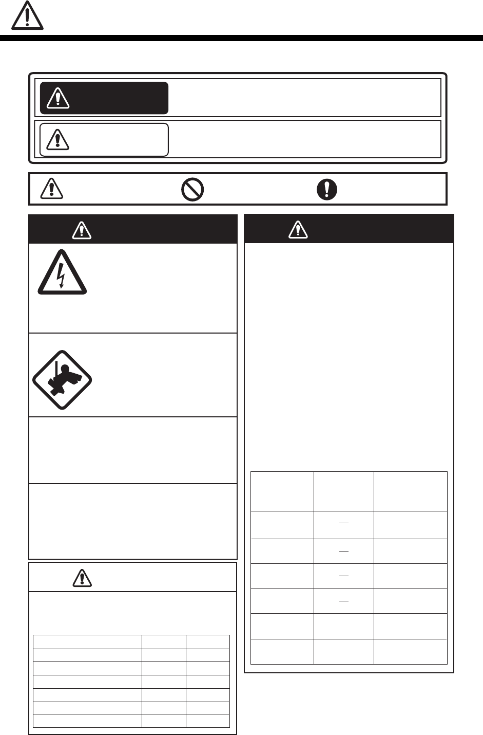
SAFETY INSTRUCTIONS
WARNING
MODEL Distance to
100 W/m2
point
Distance to
10 W/m2
point
0.7 m
WARNING
ELECTRICAL
SHOCK
HAZARD
FR-8122
XN-12A 2.1 m
Observe the following compass safe
distances to prevent deviation of a
magnetic compass.
Standard Steering
Display unit
0.95 m 0.60 m
0.80 m 0.50 m
CAUTION
CAUTION
Power supply unit
Antenna unit FR-8062 (24 rpm)
1.95 m 1.25 m
FR-8062
XN-12A (4') 0.9 m
FR-8062
XN-13A (6')
FR-8122
XN-13A 1.9 m
FR-8252
XN-12A 4.6 m
0.4 m
FR-8252
XN-13A 0.4 m 3.1 m
1.90 m 1.20 m
1.10 m 0.70 m
1.80 m 1.15 m
FR-8062 (48 rpm)
FR-8122
FR-8252
Indicates a condition that can cause death or serious
injury if not avoided.
Indicates a condition that can cause minor or moderate
injury if not avoided.
Read these safety instructions before you operate the equipment.
WARNING
CAUTION
Warning, Caution Prohibitive Action Mandatory Action
Radio Frequency
Radiation Hazard
The radar antenna emits electromagnetic radio
frequency (RF) energy which can be harmful,
particularly to your eyes. Never look directly into
the antenna aperture from a close distance
while the radar is in operation or expose
yourself to the transmitting antenna at a close
distance.
Distances at which RF radiation levels of 100
and 10 W/m2 exist are given in the table below.
Note: If the antenna unit is installed at a close
distance in front of the wheel house, your
administration may require halt of transmission
within a certain sector of antenna revolution.
Do not open the equipment
unless totally familiar with
electrical circuits and service
manual.
Only qualified personnel should
work inside the equipment.
Wear a safety belt and hard
hat when working on the
antenna unit.
Serious injury or death can result
if someone falls from the radar
mast.
Construct a suitable service platform from
which to install the antenna unit.
Serious injury or death can result if someone
falls from the radar mast.
Turn off the power at the mains switchboard
before beginning the installation.
Fire, electrical shock or serious injury can result
if the power is left on or is applied while the
equipment is being installed.
ii
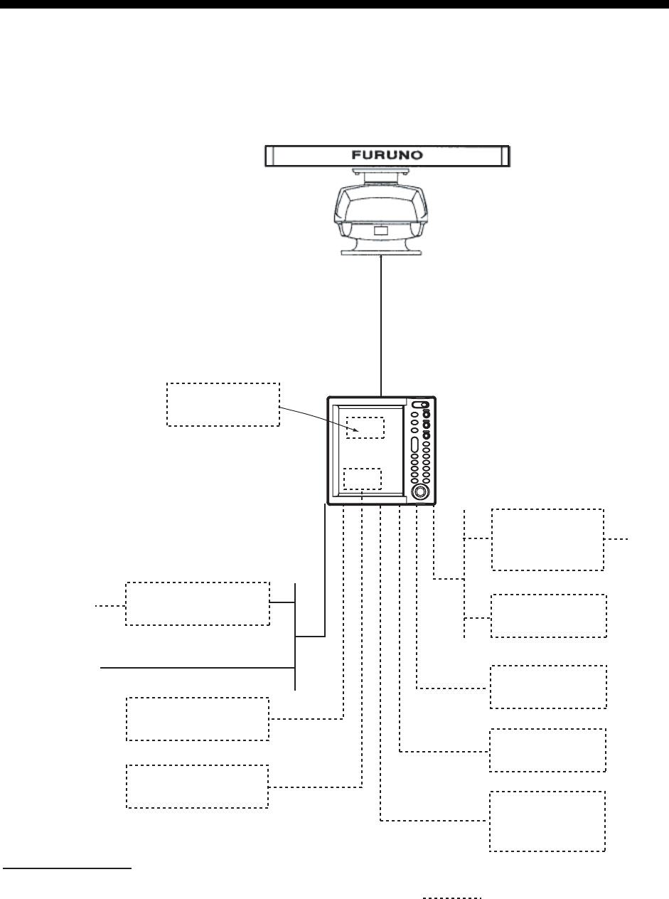
SYSTEM CONFIGURATIONS
FR-8062/8122
ANTENNA UNIT
RSB-0073-085A-XN12A/XN13A: FR-8062
RSB-0073-086A-XN12A/XN13A: FR-8122
DISPLAY UNIT
RDP-150
Auto Plotter
ARP-11
(built in
display unit)
AC-DC Power Supply
PR-240
100/110/
115/220/
230 VAC, 1
φ
12-24 VDC
Remote
Display
Commercial Monitor
(SVGA or better)
Gyro
Converter
AD-100
Heading Sensor
PG-1000
NMEA
DEVICE
NMEA
DEVICE
External
Buzzer
OP03-136
: Optional equipment
Gyrocompass
Category of units
A
ntenna unit: Exposed to weather
A
ll other units: Protected from weather
RGB
iii
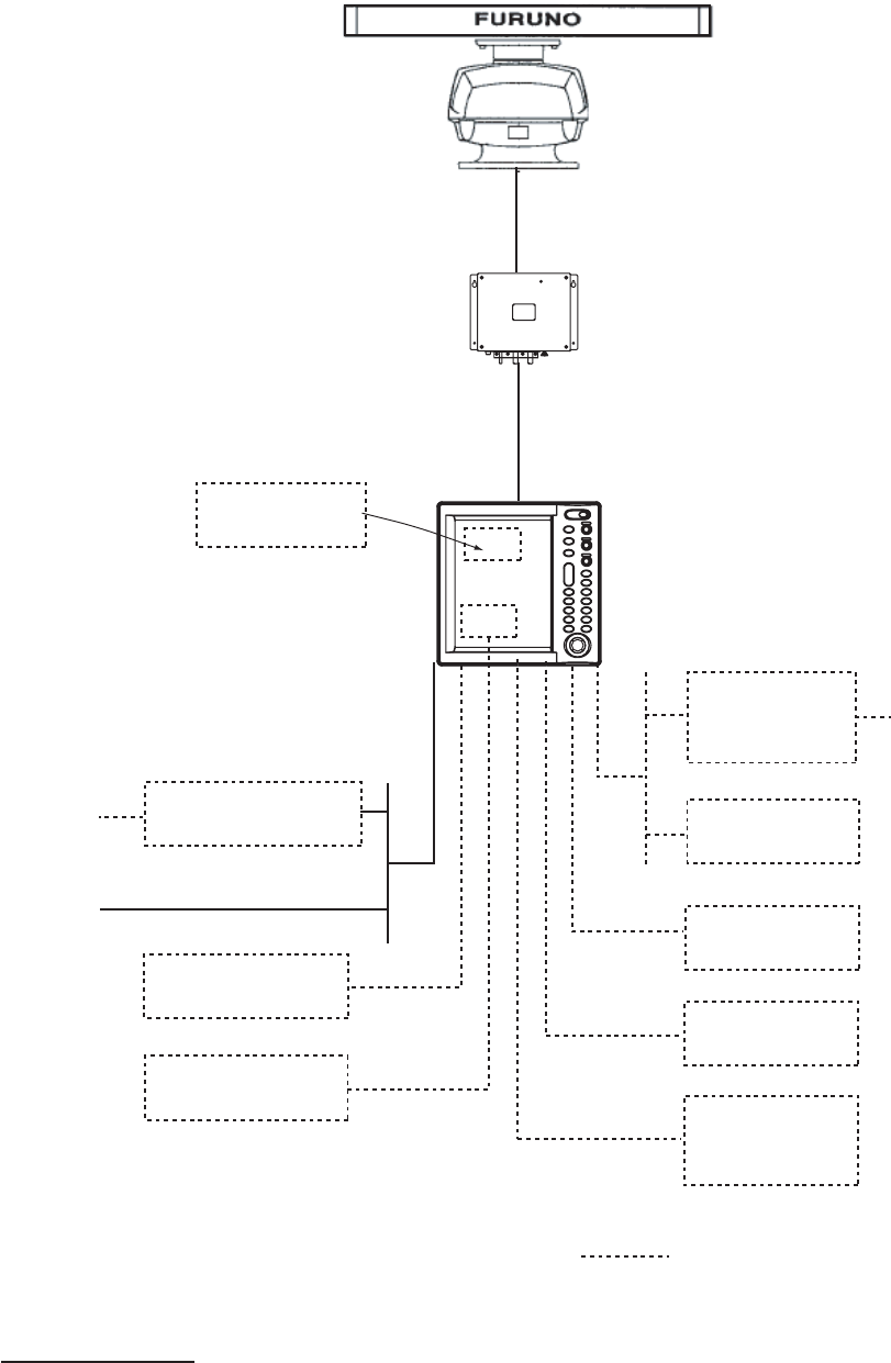
FR-8252
ANTENNA UNIT
RSB-0073-087A-XN12A/XN13A
POWER SUPPLY UNIT
PSU-008
Auto Plotter
ARP-11
(built in
display unit)
AC-DC Power Supply
PR-240
12-24 VDC
Remote
Display
Gyro
Converter
AD-100
Heading Sensor
PG-1000
NMEA
DEVICE
NMEA
DEVICE
External
Buzzer
OP03-136
: Optional equipment
100/110/
115/220/
230 VAC, 1
φ
Gyrocompass
Category of units
Antenna unit: Exposed to weather
All other units: Protected from weather
RGB
Commercial Monitor
(SVGA or better)
DISPLAY UNIT
RDP-150

iv
EQUIPMENT LISTS
Standard Supply
Name Type Code No. Qty Remarks
Antenna unit
XN12A-RSB-0073-085A
-
1
FR-8062, 1255 mm,
24/36/48 rpm
XN13A-RSB-0073-085A
- FR-8062, 1795 mm,
24/36/48 rpm
XN12A-RSB-0073-086A
- FR-8122, 1255 mm,
24/36/48 rpm
XN13A-RSB-0073-086A
- FR-8122, 1795 mm,
24/36/48 rpm
XN12A-RSB-0073-087A
- FR-8252, 1255 mm,
24/36/48 rpm
XN13A-RSB-0073-087A
- FR-8252, 1795 mm,
24/36/48 rpm
Display unit RDP-150 - 1
Power supply unit PSU-008 - 1 For FR-8252
Installation
materials
CP03-30801 008-552-960 1 For antenna unit
CP03-30700 000-090-471
1
10 m signal cable for
FR-8062/8122
CP03-30710 000-090-472 15 m signal cable for
FR-8062/8122
CP03-30720 000-090-473 20 m signal cable for
FR-8062/8122
CP03-30730 000-090-474 30 m signal cable for
FR-8062/8122
CP03-30500 000-083-620
1
10 m signal cable for FR-8252
CP03-30510 000-083-621 15 m signal cable for FR-8252
CP03-30520 000-083-622 20 m signal cable for FR-8252
CP03-30530 000-083-623 30 m signal cable for FR-8252
CP03-30900 000-090-464 CP03-30901 & power cable for
display unit
Spare parts SP03-15401 008-553-040 1 15A fuse, 3pcs and 10A fuse,
3pcs
*: See lists on the back of this manual.

v
Optional Supply
Name Type Code No. Remarks
External buzzer OP03-136 000-086-443 See ch. 4.
AC-DC Power Supply PR-240 - For AC ship’s mains
MJ-A7SPF0007-0
50C
000-144-418-10 w/7P plug at one end, 5m
MJ-A6SPF0003-0
50C
000-154-054-10 w/6P plug at one end, 5 m
MJ-A6SPF0007-1
00C
000-159-695-10 For compass, 10 m
MJ-B24LPF0008-
100
000-145-125 10 m for remote display
MJ-B24LPF0008-
200
000-145-126 20 m for remote display
Cable assy.
MJ-B24LPF0008-
300
000-145-127 30 m for remote display
Auto plotter ARP-11 008-523-050 See ch. 4.
Installation materials CP03-31001 008-556-830 Installation materials for remote
display, see ch. 4.
RGB kit OP03-195 008-553-110 See ch. 4.
Remote controller RCU-019 000-090-945 With 5 m cable
vi
This page intentionally left blank.

1-1
1. MOUNTING
1.1 Antenna Unit
Mounting considerations
• The antenna unit is generally installed either on top of the wheelhouse or on the radar
mast on a suitable platform. Locate the antenna unit where there is a good all-round view.
Any obstruction will cause shadow and blind sectors. A mast for instance, with a diameter
considerably less than the horizontal beamwidth of the radiator, will cause only a small
blind sector, but a horizontal spreader or crosstrees in the same horizontal plane as the
antenna unit would be a much more serious obstruction; you would need to place the
antenna unit well above or below it.
• It is rarely possible to place the antenna unit where a completely clear view in all
directions is available. Thus, you should determine the angular width and relative bearing
of any shadow sectors for their influence on the radar at the first opportunity after fitting.
• To lessen the chance of picking up electrical interference, avoid where possible routing
the signal cable near other onboard electrical equipment. Also avoid running the cable in
parallel with power cables.
• A magnetic compass will be affected if the antenna unit is placed too close to it. Observe
the compass safe distances mentioned in the SAFETY INSTRUCTIONS to prevent
interference to a magnetic compass.
• Do not paint the radiator aperture, to ensure proper emission of the radar waves.
• When this radar is to be installed on larger vessels, consider the following points:
• The signal cable run between the antenna and the display units comes in lengths of
10 m, 15 m, 20 m and 30 m.
• Deposits and fumes from a funnel or other exhaust vent can adversely affect the
aerial performance and hot gases may distort the radiator portion. The antenna unit
must not be mounted where the temperature is more than 70°C.
As shown in the figure below, the antenna unit may be installed on the bridge, on a common
mast or on the radar mast.
(a) On bridge (b) Common mast (c) Radar mast
Mounting methods
1. MOUNTING
1-2
Mounting procedure
Referring to the outline drawing at the back of this manual, drill five holes in the mounting
platform: four holes of 15 mm diameter for fixing the antenna unit and one hole of 25-30 mm
diameter for the signal cable.
Fastening the radiator to the radiator bracket
For your reference, the antenna installation materials list appears in the packing list at the
back of this manual.
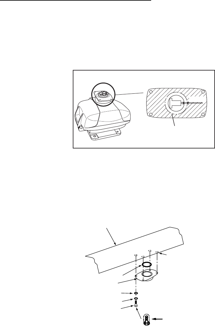
1. Remove the radiator cap from the radiator bracket.
2. Coat contacting surface between the antenna radiator and the radiator bracket with
silicone sealant as shown in the figure below.
RADIATOR BRACKET
(top view)
Coat hatched area with
silicone sealant.
10mm
Coating the antenna with silicone sealant
3. Coat threaded holes on the antenna radiator with silicone sealant.
4. Grease the O-ring and set it to the radiator bracket.
5. Lay the antenna radiator on the radiator bracket.
6. Coat the radiator fixing bolts (4 pcs.) with silicone sealant. Fasten the antenna radiator to
the radiator bracket with the radiator fixing bolts, flat washers and spring washers.
Flat washer
Spring washer
Hex head bolt
(M8x30)
Radiator bracket
Coat bolts with
silicone sealant.
Antenna
radiator
O-ring
Coat threaded
holes with silicone
sealant.
Fastening the radiator bracket to the antenna unit chassis
1. MOUNTING
1-3
Mounting the antenna unit
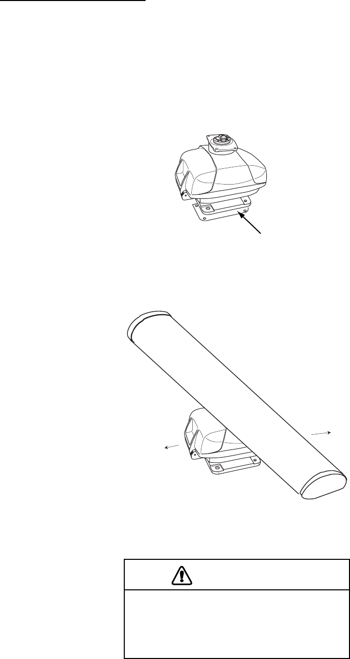
The antenna unit can be mounted using the fixing holes on the outside (200x200 mm) or
inside (140x150 mm) the antenna unit.
Using outside fixing holes of the antenna housing
Use the hex head bolts (supplied) to mount the antenna unit as below.
1. Lay the corrosion-proof rubber mat (supplied) on the mounting platform.
Rubber
mat
Location of rubber mat
2. Lay the antenna unit on the mounting platform, orienting it as shown in below.
STERN
BOW
Antenna unit
CAUTION
Do not lift the Antenna unit by the
radiator; lift it by the housing.
The radiator may be damaged.
1. MOUNTING
1-4
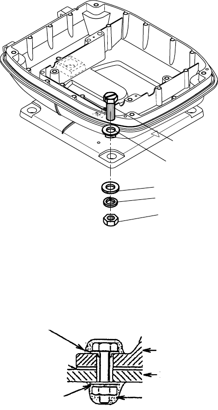
3. Insert four hex bolts (M12x60, supplied) and seal washers (Ф30, supplied) from the top
of the antenna housing, as shown below.
Hex bolt
Seal washer
Flat washer
Spring washer
Nut
Fixing the antenna unit chassis
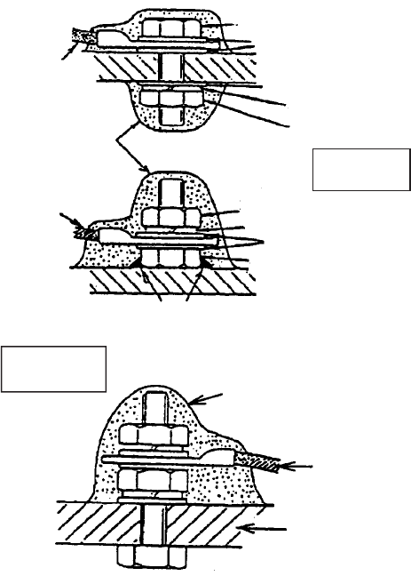
4. Pass flat washers (M12, supplied), spring washers (M12, supplied) and nuts (M12,
supplied) onto hex bolts. Fasten by tightening nuts. Do not fasten by tightening the hex
bolts; seal washers may be damaged.
Antenna
unit
Mounting
platform
Silicone
sealant
Flat washer
Rubber mat
Seal washer
How to fasten antenna unit to mounting platform
5. Coat flat washers, spring washers, nuts and exposed parts of bolts with anticorrosive
sealant.
6. Prepare ground point on mounting platform (within 300 mm of ground terminal on
antenna unit) using M6x25 bolt, nut and flat washer (supplied).
7. Run the ground wire (RW-4747, 340 mm, supplied) between the ground terminal and
ground point.
1. MOUNTING
1-5
8. Coat ground terminal and ground point with silicone sealant as shown below.
Ground
wire
Hex bolt
Flat washer
Spring washer
Flat washer
Hex nut
Silicone
sealant
Hex nut
Weld here.
Silicone
sealant
Ground
wire
antenna
unit
OR
Flat washer
Spring washer
Ground
wire
GROUND
TERMINAL
GROUND
POINT
Hex nut
How to coat ground point and ground terminal with silicone sealant
1. MOUNTING
1-6
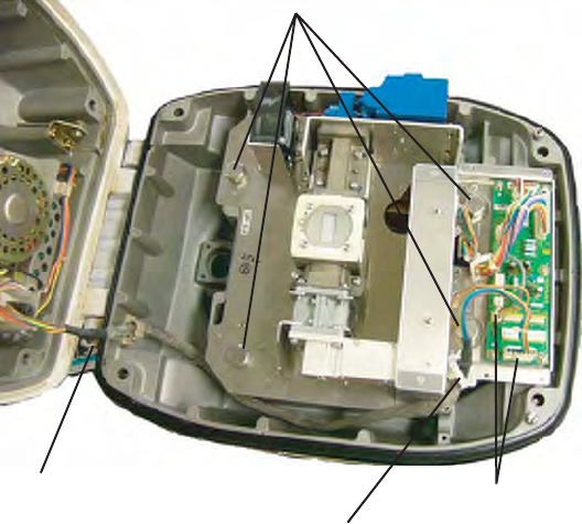
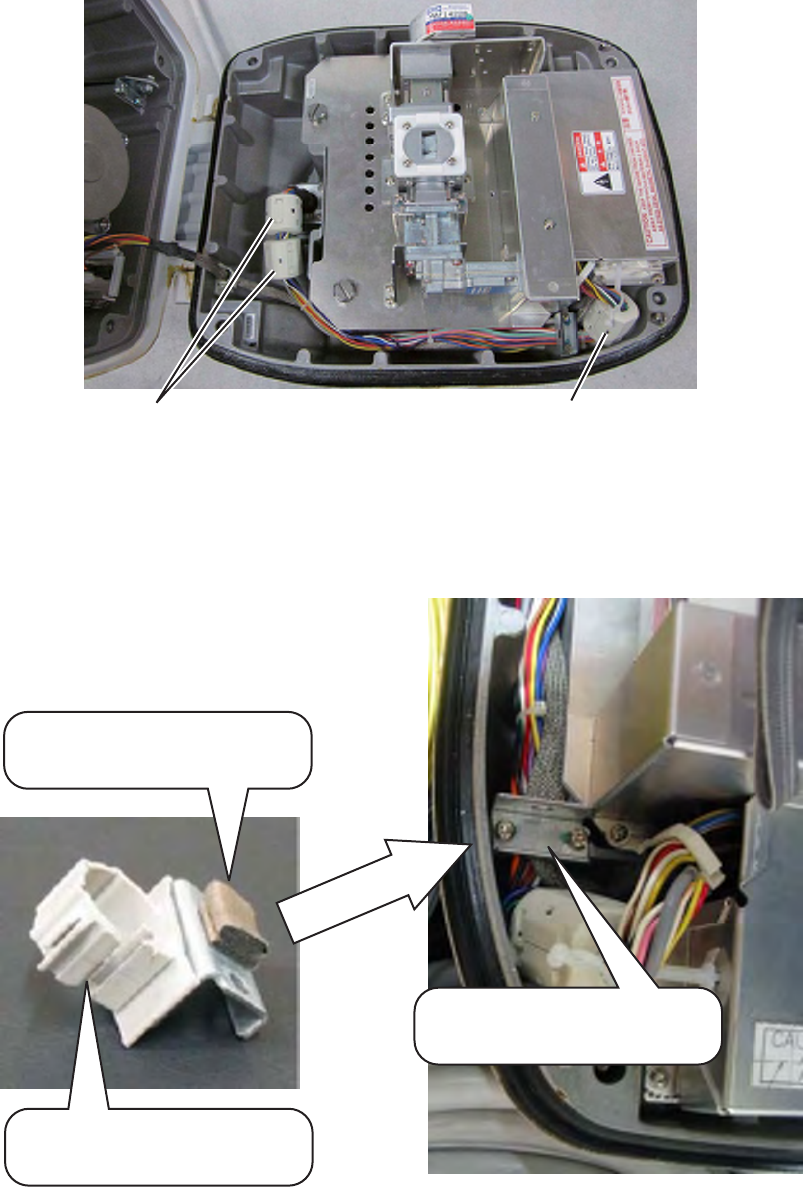
Using inside fixing holes of the antenna housing
This method requires removal of the RF unit in the antenna unit to access inside fixing
holes. Use hex head bolts, flat washers, spring washers and nuts (local supply) to mount
the antenna unit, confirming length of bolts.
1. Unfasten four antenna bolts on the cover to open the antenna unit.
2. Unfasten four screws on the RTB cover to remove it.
3. Unplug connector J827 and J834 on the RTB board.
4. Separate upper chassis from lower chassis by removing two hex head bolts (M8x25).
5. Remove RF unit by unfastening four hex head bolts.
Hex. bolt(M10X20)
Hex. bolt(M8X25) J827, J834
Remove from cable clamp
Antenna unit, opened
7. Lay the corrosion-proof rubber mat (supplied) on the mounting platform.
8. Fasten the lower chassis to the mounting platform with hex head bolts, spring washers,
flat washers and nuts (local supply), and then coat flat washers, nuts and exposed parts
of bolts with silicone sealant. Cut a slit in the rubber bushing and insert bolt into the
bushing. Do not use seal washers.
9. Reassemble RF unit, cover and chassis.
10. Set four knob caps (supplied) into outside fixing holes.
11. Do steps 6-8 in “Outside fixing holes”.
1. MOUNTING
1-7
Connecting the signal cable
Only the signal cable runs from the display unit (power supply unit in case of FR-8252) to
the antenna unit. In order to minimize the chance of picking up electrical interference, avoid
where possible routing the signal cable near other onboard electrical equipment. Also, avoid
running the cable in parallel with power cables. Pass the cable through the hole and apply
sealing compound around the hole for waterproofing.
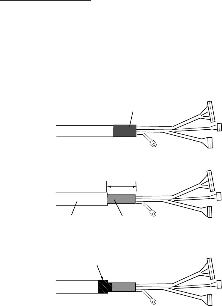
• Fabricating the signal cable
This type of signal cable is used with other models of radar. For this model, the following
fabrication is required.
1. Remove shrink tubing from the signal cable.
Remove shrink tubing.
2. Remove vinyl sheath approx. 50 mm.
Cut vinyl sheath approx. 50 mm.
Braided shield
Vinyl sheath
3. Wrap vinyl tape at the end of the vinyl sheath.
Vinyl tape
1. MOUNTING
1-8
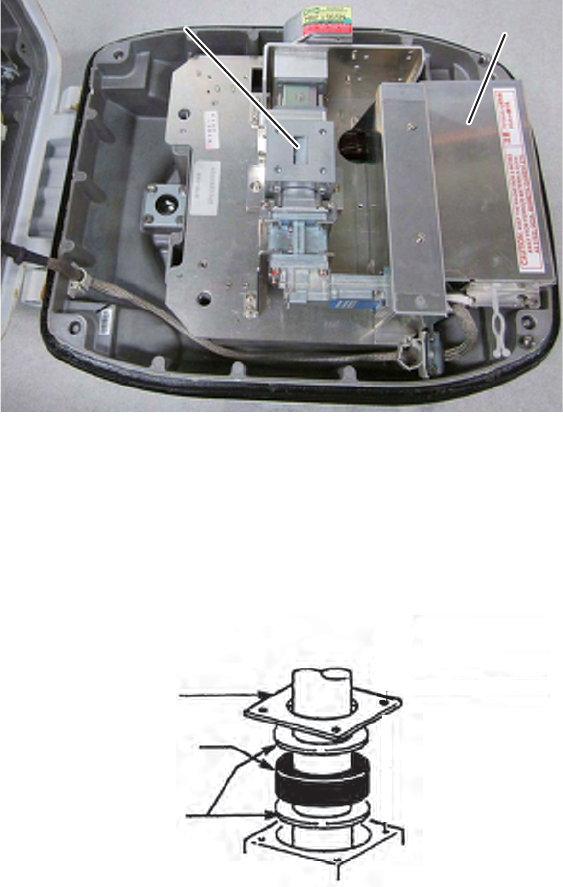
• Connecting the signal cable
1. Open the antenna cover by loosening four bolts, and then fix the stay.
RTB board cover
RTB board cover
Cable entry
Cable entry
Antenna unit chassis, cover opened
2. Unfasten the cable gland assembly (plate, gasket, flat washer). The plate may be
discarded.
3. Pass the signal cable with connector through the bottom of the antenna unit chassis.
Pass the cable through the gland assembly as shown below.
Gasket support
Gasket
Flat washer
Cable entry
Passing the signal cable through the cable gland assembly
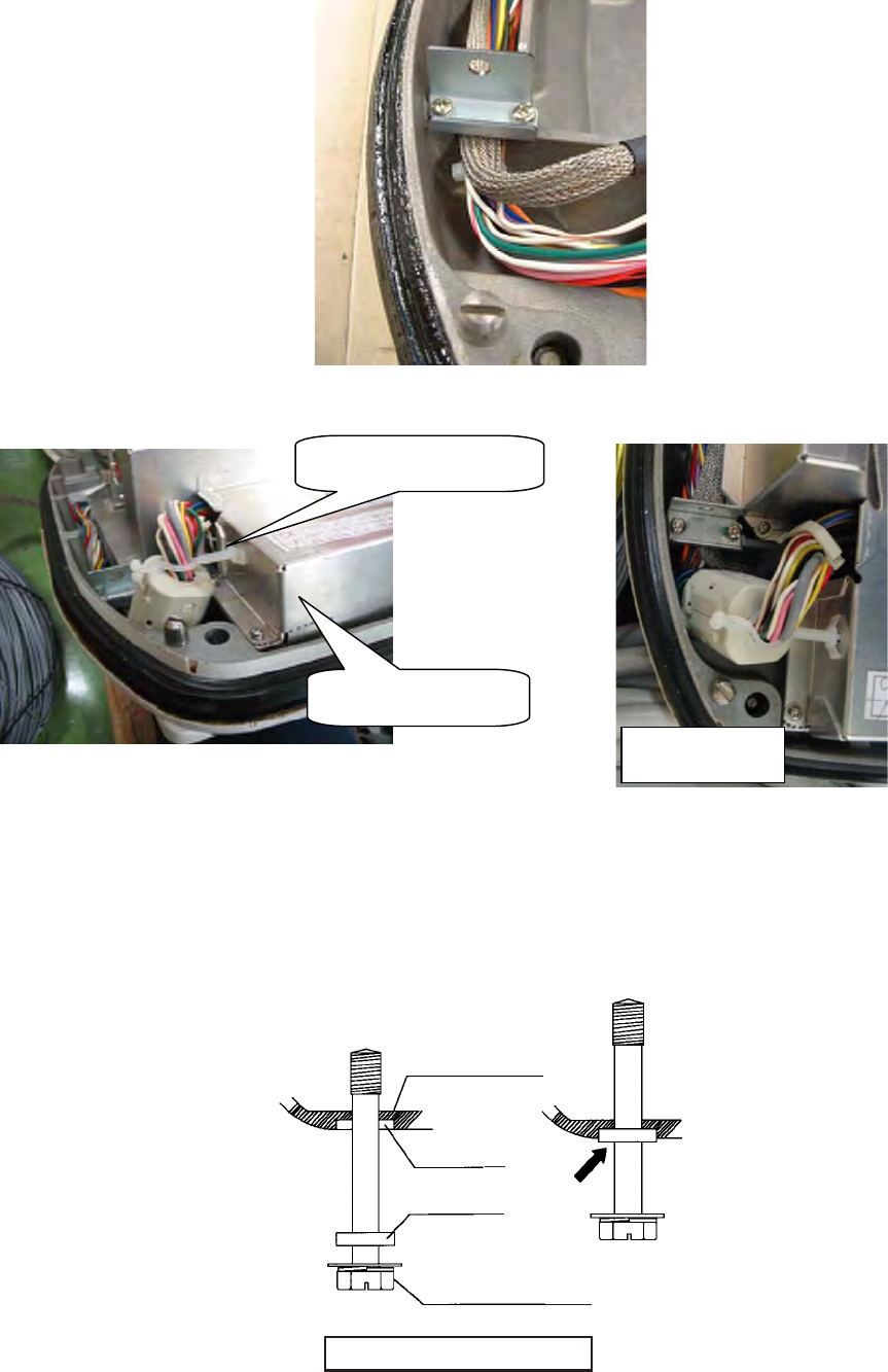
4. Fasten the gasket support with four bolts. Using one of the four bolts, fasten the
crimp-on lug to the shield wire.
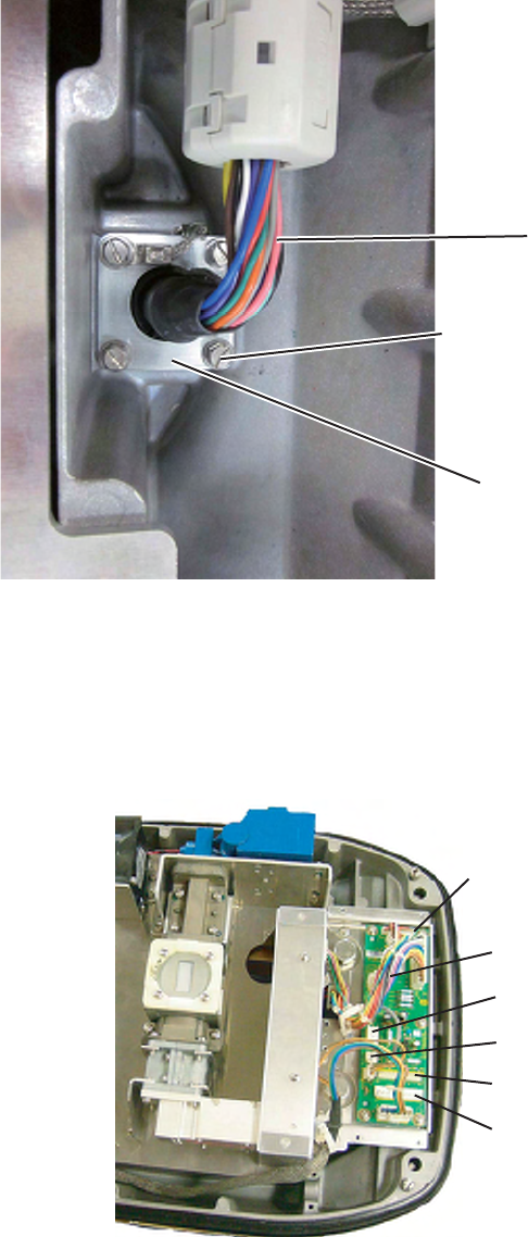
1. MOUNTING
1-9
5. Fasten the shielded part of the signal cable with shield clamp (installation material) as
shown below.
Signal cable
Fix shield wire with bolt.
Gasket support
How to fix signal cable in cable gland
6. Unfasten four screws to remove the RTB board cover.
7. Connect the plugs of the signal cable to the RTB board.
FR-8062, FR-8122: J821, J823, J824, J822
FR-8252: J821, J823, J824, J820
RTB board
J820
J823
J822
J824
J821
Connecting to the RTB board
8. Reattach the RTB board cover.
1. MOUNTING
1-10
9. Attach three EMI cores to the signal cable as shown below.
EMI Core RFC-13 (2 pcs) EMI Core RFC-H13 (1 pc)
Antenna unit chassis, cover opened
10. Fix the signal cable with the cable clamp as follows.
a) Dismount the cable clamp plate and remove clamp and gasket.
Remove gasket.
Remove clamp.
Cable clamp plate
1. MOUNTING
1-11
b) Run the signal cable as shown below.
c) Fix the signal cable with cable clamp as shown below.
11. Release the stay and close the cover. Loosely fasten the antenna bolts; you will have to
make some adjustments inside after completion of wiring.
Note: When closing the cover, set the gaskets to grooves in the bottom chassis, then
tighten bolts.
BOTTOM
CHASSIS
GASKET
GROOVE
ANTENNA BOLT
Torque : 9.8 ±0.1 N m
.
RTB board cover
Top view
Cable clamp
1. MOUNTING
1-12
1.2 Display Unit
The display unit can be mounted on a tabletop, on the overhead or flush mounted in a
console or panel.
Mounting considerations
When selecting a mounting location for the display unit, keep the following in mind:
• Keep the display unit out of direct sunlight.
• The temperature and humidity at the mounting location should be moderate and stable.
• Locate the unit away from exhaust pipes and vents.
• The mounting location should be well ventilated.
• Mount the unit where shock and vibration are minimal.
• Keep the unit away from electromagnetic field generating equipment such as motors and
generators.
• For maintenance and checking purposes, leave sufficient space at the sides and rear of
the unit and leave slack in cables. Minimum recommended space is shown in the outline
drawing for the display unit.
• A magnetic compass will be affected if the display unit is placed too close to it. Observe
the compass safe distances shown in the SAFETY INSTRUCTIONS to prevent
disturbance to the magnetic compass.
1. MOUNTING
1-13
Mounting procedure
Tabletop mounting
Follow the procedure below to mount the display unit on a tabletop.
1. Fix the hanger by using four self-tapping screws (5x20).
2. Screw knob bolts in display unit, set it to the hanger, and tighten the knob bolts.
Knob
Hanger
Fix with four self-tapping screws.
Mounting dimensions of display unit
Overhead mounting
Note: For the overhead mounting, reinforce the mounting location and secure the hanger,
with bolts, nuts and washers (local supply).
Attach two rubber cushions to the display unit as shown in the figure below. Then fix the unit
with hanger.
Remove paper tape and attach.
Match the centers.
Rubber cushion
Match the edges.
1. MOUNTING
1-14
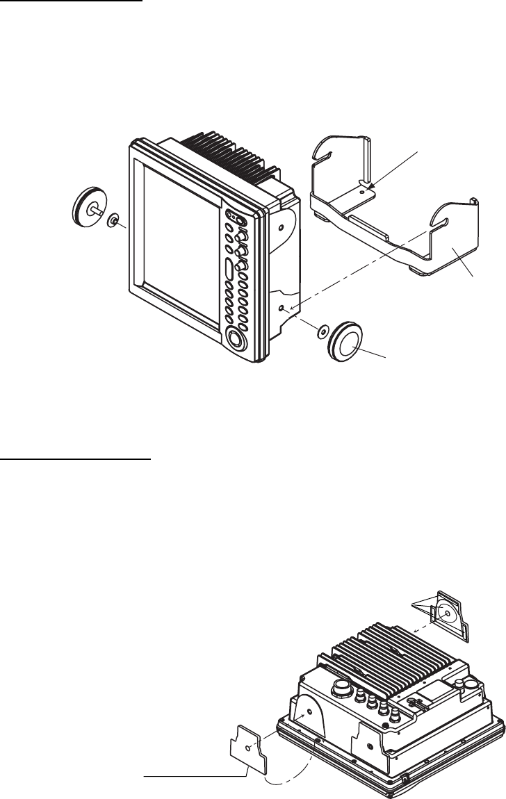
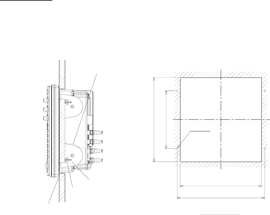
Flush mounting
1. Prepare a cutout in the mounting location whose dimensions are as shown below.
2. Detach two rubber cushions from the display unit.
3. Insert the flush mounting sponge and four threaded rods from the rear side of the display
unit, and then set the display unit to the mounting location.
4. Fix the display unit by using four wing nuts from the rear side of the display unit.
292±1
200±0.5
282±1.0
303±0.5
4-φ5
CUTOUT DIMENSIONS
Wing nut
Threaded rod
Flush mounting sponge
Detach two rubber cushions.
Flush mounting of display unit
1. MOUNTING
1-15
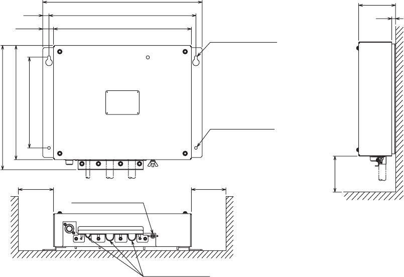
1.3 Power Supply Unit
A power supply unit is shipped with the FR-8252, because of its high power consumption.
The power supply unit can be installed almost anywhere provided the location is dry,
well-ventilated, sufficient maintenance space is provided and is installed within 5 m (cable
length) from the display unit. To fix the unit, use four self-tapping screws (5x20).
Note: Do not install the power supply unit on the overhead; install it on the deck or
bulkhead.
#200
2 -
φ
6
13
22.5
333
370 ± 0.5
288
2 - R3
FIXING NOTCH
FIXING HOLES
190 ± 0.5
239
260
77
8
CABLE ENTRY
GND TERMINAL
#100
#: Service space
Power supply unit
1. MOUNTING
1-16
This page is intentionally left blank.
2-1
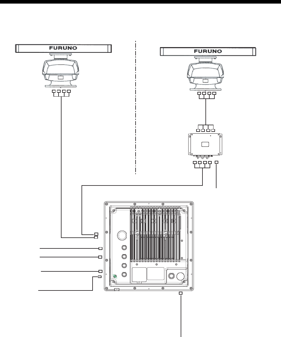
2. WIRING
2.1 Standard Wiring
FR-8252
Power supply unit
PSU-008
FR-8062/8122
Display unit
RDP-150
RW-9771
(10/15/20/30m)
MJ-B24LPF0012-xxx
(10/15/20/30m)
MJ-B24LPF0011-050 (5m)
MJ-A3SPF0018-050ZC
(5m)
12-24 VDC
MJ-A7SPF0007-050C
MJ-A7SPF0007-050C
NMEA device
NMEA device
Heading sensor
MJ-A6SPF0003-050C
MJ-A6SPF0007-100C
External buzzer,
PC
MJ-A7SPF0007-050C
VL3P-VV-S2X2C-AA050
(5m)
12-24 VDC
Antenna unit
RSB-0073 Antenna unit
RSB-0073