Furuno USA 9ZWRTR087A Marine Radar User Manual inst man part 2
Furuno USA Inc Marine Radar inst man part 2
Contents
- 1. inst man part 1
- 2. inst man part 2
inst man part 2
2. WIRING
2-2
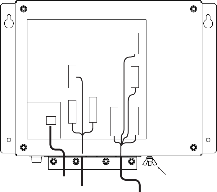
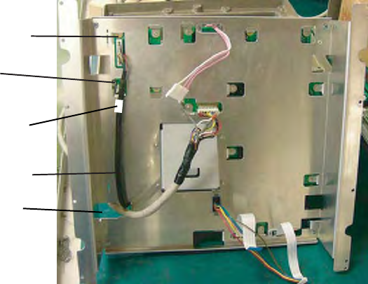
2.2 Wiring the Power Supply Unit
Cabling
1. Unfasten four screws to remove the cable clamp.
2. Unfasten four screws to remove the cover.
3. Attach the connectors of three cables as shown in the figure below.
POWER Board 03P9419
J1 3P
VL3P-VV-S2X
2C-AA050
cable
(to 12-24 VDC)
MJ-B24
LPF0011-050
cable
(to display unit)
V
H
9
N
H
13
V
H
4
J3
J4
J5
Ground
terminal
V
H
1
0
J12
N
H
1
4
J14
V
H
5
J13
V
H
2
J11
Antenna cable
RW-9771
(03S9771)
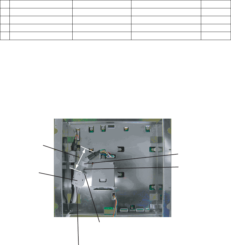
4. Lay three cables in respective slots referring to the figure above.
5. Reattach the cover and the cable clamp.
6. Connect a ground wire (local supply, IV-2sq) between the ground terminal and ship’s
ground.
2. WIRING
2-3
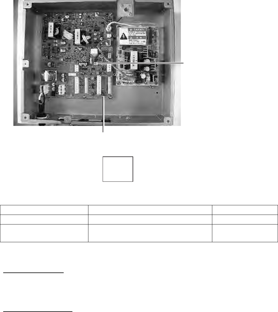
Jumper block, slide switch setting
The jumper block JP1 and slide switch S112 on the PWR board (03P9419) must be set
according to radar model. Open the unit, locate JP1 and S112 and set them as below.
FR-8252
S
S112
T
MODEL1964C
Jumper block JP1
("short" for FR-8252 radar;
remove dummy connector and
attach connector assy.
XH2P-L40-ACR.)
Slide switch S112
(Upward position
for FR-8252)
Power supply unit, inside view
Jumper block, slide switch Function Setting
JP1 Enables/disables motor slow start circuit. Short (disable)
S112 TUNE voltage selector (0-12 V, 0-32 V) Upward position
(0-12 V)
Power requirement, replacement of fuses
Power requirement
The power for the power supply unit and display unit must be drawn from the same power
switch on the power terminal board.
Replacement of fuses
The power supply unit is shipped with a 15 A fuse(for connection to 12 VDC battery).
Replace the fuse with a 7 A (supplied) when the ship’s battery is 24 VDC.

2. WIRING
2-4
2.3 Port for External Devices
External equipments can be connected here as shown below.
NMEA1(7P) NMEA2(7P) HDG (6P) PC/EXT-BUZZER
(7P)
NMEA sentence
device NMEA sentence
device Heading sensor External buzzer,
PC, etc.
This equipment can receive the following NMEA 0183 format sentences from other
equipment. You will need the optional NMEA cable to connect with external equipment.
• Course: VTG> RMC
• Waypoint Range: BWR> BWC> RMB, Bearing: BWR> BWC (> RMB*1)
• Heading (True): HDT> VHW> HDG*2> HDM*2> VHW*2
• Heading (Magnetic): HDG> HDM> VHW> HDT*2> VHW*2
• Ship’s speed: Over ground: VTG>RMC> VHW, Through water: VHW
• Date: ZDA
• Time: ZDA
• Own ship’s position: GNS>GGA>RMC> GLL
• Depth: DPT>DBT
• Wind speed and angle*3: True: MWV>VWT, Relative: MWV>VWR
• Water temperature: MTW
*1: Available when true bearing.
*2: Variation data is required.
*3: True or Relative is changed with menu.
3-1
3. SETTING UP THE EQUIPMENT
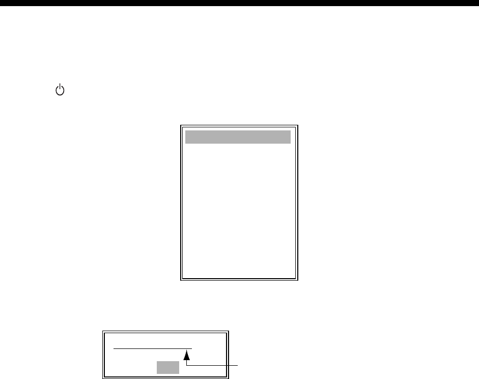
3.1 Setting Language
At the first power application after installation, choose a language as follows.
1. Press /BRILL key to turn the power on.
“Now Initializing…” appears and after a while the window below appears.
Language English
Language Francais
Language Espanol
Language Deutsch
Language Italiano
Language Portugues
Language Dansk
Language Svensk
Language Norsk
Language Chinese
Language Japanese
Language Thai
2. Rotate the trackball to choose language desired and press the ENTER key.
The confirmation window appears.
Yes
No
Language English OK?
Changes with language chosen.
3. Choose Yes and press the ENTER key.
3. SETTING UP THE EQUIPMENT
3-2
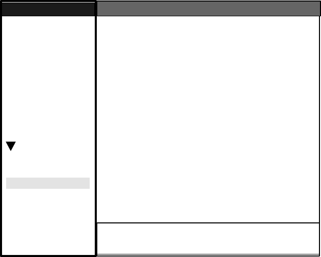
3.2 Opening the Installation Menu
After you have installed the equipment, set it up as follows.
1. Press the MENU key. The main menu appears on the screen.
2. Rotate the trackball downward to choose Installation. The installation menu appears in
gray to right side of the screen.
3. While pressing down the CANCEL/HL OFF key, press the MENU key five times to
activate the Installation menu.
[ENTER]: Enter [CANCEL/HL OFF]: Back
[MENU]: Exit
System
GPS
Mark
Custom 1
Custom 2
Custom 3
Target
ARP
AIS
Tuning
Type
View Position
Input Source
Language
Purpose
Antenna Height
Heading Adjust
: Center
: Main
: 5 m
: 0 °
: 8062
: English
: Sea
Tuning Initial Adjust
Manual MBS Adjust
Auto Installation Setup**
Manual Timing Adjust
Local Time Offset
: 0
: - 0.1 H
: 0
Menu Installation
Initial
Factory
Sector Blank 1**
Installation Total TX Time* : 000000.5 h
Total On Time* : 000000.6 h
* : Displayed when scrolled.
Memory Clear*
** : Set the Sector Blank to "Off" in order to
execute Auto Installation Setup in the
Installation menu.
GPS Buoy
Video Initial Adjust : 0
Antenna Rotation : Rotate
4. Press the ENTER key. The highlighted cursor appears in the Installation menu.
5. Rotate the trackball downward or upward to choose an item in the Installation menu.
6. Press the ENTER key to show setting window.
7. Rotate the trackball downward or upward to choose an option.
8. Press the ENTER key to confirm setting.
9. Finally, press the MENU key to close the main menu.
Basic Settings
Language: Choose an appropriate language.
Purpose: Choose the purpose of this radar among River, Sea and IEC. The default setting
is Sea.
River: To use this radar on a river.
Sea: To use this radar on high seas.
IEC: To use this radar as the type approved radar.
Type: Choose type of this radar among 8062 (6 kW radar), 8122 (12 kW radar) and 8252
(25 kW radar) to agree with the specifications of the antenna unit. The default setting
is 8062. Unsuitable setting may result in malfunction.
3. SETTING UP THE EQUIPMENT
3-3
View Position: Choose the operating position for this radar among Left, Left-Center, Center,
Right-Center and Right to view echo colors correctly. The default setting is Center.
Left: When operating this radar at the left side.
Left-Center: When operating this radar at the left-center side.
Center: When operating this radar at center position.
Right-Center: When operating this radar at the right-center side.
Right: When operating this radar at the right side.
Approx. angle of the view position as follows.
LCD screen
30°
15°
30°
15°
0°
Left
Left-Center
Center Right
Right-Center
Note: The radar echo and trail echo are adjusted by the View Position. The
characters are not adjusted. This setting is also reflected on an external monitor
(option).
Input Source: Choose the input source between Main and Sub. The default setting is Main.
Main: When using this display unit as main radar.
Sub: When using this display unit as sub display. For Sub, the “Video Initial
Adjust” is required (page 3-6).
Antenna Height: Set the height of the antenna above the water surface among 5, 10, 15,
20, 30, 40 and 50 m. The default setting is 15 m.
Antenna Rotation: “Rotate,” the default setting, stops transmission when the antenna is
not rotating. “Stop” transmits radar pulses without rotating the antenna.
Local Time Offset: To display local time on the screen, set the time difference from the
UTC.
Memory Clear: Restore the default settings. However, Purpose, Type, View Position and
Input Source are not restored.
Heading Adjustment
You have mounted the antenna unit facing straight ahead in the direction of the bow.
Therefore, a small but conspicuous target dead ahead visually should appear on the
heading line (zero degrees).
In practice, you will probably observe some small error on the display because of the
difficulty in achieving accurate initial positioning of the antenna unit. The following
adjustment will compensate for this error.
1. Set ship’s heading toward a suitable target (for example, ship or buoy) at a range
between 0.125 and 0.25 nautical mile.

3. SETTING UP THE EQUIPMENT
3-4
2. Transmit the radar at 0.25 nm range and measure the bearing of that target relative to
ship’s heading with an EBL.
3. Open the Installation menu, and choose Heading Adjust.
4. Press the ENTER key to show the HEADING ADJUST window.
S
S
0 °
(0 ° ∼ 359 °)
5. Rotate the trackball upward or downward to set the value measured at the step 2 above.
Confirm that the target shows dead ahead on the screen.
6. Press the ENTER key to conclude the setting.
Auto Installation Setup
When this item is executed, the tuning, timing, video and MBS are automatically adjusted.
Note: Before executing this procedure, confirm that Sector Blank 1 and Sector Blank 2 are
off.
1. Transmit the radar at 48 nm range.
2. Choose Auto Installation Setup from the installation menu and press the ENTER key.
3. Rotate the trackball to choose Yes, and then press the ENTER key.
Automatically, the tune adjustment begins, indicating “Tuning adjusting….” Then, the timing
adjustment, video adjustment and MBS adjustment are executed automatically, indicating
“Timing adjusting…”, “Video adjusting…”, and “MBS adjusting…” in that order. After the
adjustment is completed, the window disappears.
If you are not satisfied with the result of the Auto Installation Setup, execute Manual Timing
Adjust, Tuning Initial Adjust, Manual MBS Adjust and Video Initial Adjust as follows.
Tuning Initial Adjust
1. Transmit the radar at 48 nm range.
2. Open the Installation menu, and choose Tuning Initial Adjust.
3. Press the ENTER key to show the setting window.
4. Rotate the trackball to choose Yes, and then press the ENTER key. The tune
adjustment begins, indicating “Tuning adjusting….” After the adjustment is completed,
the window disappears.

3. SETTING UP THE EQUIPMENT
3-5
Manual Timing Adjust
This adjustment ensures proper radar performance, especially on short ranges. The radar
measures the time required for a transmitted echo to travel to the target and return to the
source. The received echo appears on the display based on this time. Thus, at the instant
the transmitter is fired, the sweep should start from the center of the display (sometimes
called sweep origin.)
A trigger pulse generated in the display unit goes to the antenna unit through the signal
cable to trigger the transmitter (magnetron). The time taken by the signal to travel up to the
antenna unit varies, depending largely on the length of signal cable. During this period the
display unit should wait before starting the sweep. When the display unit is not adjusted
correctly, the echoes from a straight local object (for example, a harbor wall or straight pier)
will not appear with straight edges – namely, they will be seen as “pushed out” or “pulled in”
near the picture center. The range of objects will also be incorrectly shown.
(1) Target pulled (2) Correct (3) Target pushed outward
Examples of improper and correct sweep timing
1. Transmit on the shortest range and confirm that gain and A/C SEA are properly
adjusted.
2. Visually select a target which forms a straight line (harbor wall, straight piers).
3. Open the Installation menu and choose Manual Timing Adjust.
4. Press the ENTER key to show the setting window.
5. Rotate the trackball to straighten the target selected at step 2, and then press the
ENTER key to finish.
3. SETTING UP THE EQUIPMENT
3-6
Manual MBS Adjust
Main bang (black hole), which appears at the display center on short ranges, can be
suppressed as follows.
1. Transmit the radar on the short range.
2. Open the Installation menu and choose Manual MBS Adjust.
3. Press the ENTER key to show the setting window.
4. Rotate the trackball to suppress main bang (between 0 and 255).
5. Press the ENTER key to finish.
Video Initial Adjust
After completing Auto Installation Setup, you can fine tune the video signal.
1. Transmit the radar and set as follows.
Gain: one o’clock A/C Sea: zero A/C Rain: zero
Echo Average: Off Noise Rejecter: Off Interference Rejecter: Med.
2. Open the Installation menu and choose Video Initial Adjust.
3. Press the ENTER key to show the setting window.
4. Rotate the trackball to adjust the video so that the white noise slightly appears. The
setting range is 0 to 31. The greater the value, the higher the gain.
5. Press the ENTER key to finish.
Note: If the display unit is used as a Sub-display, set the “Input Source” to “Sub” and
perform the Video Initial Adjust as mentioned above so that the echo presentation on
the sub-display is the same as that on the main display.
4-1
4. OPTIONAL EQUIPMENT
4.1 ARP Kit ARP-11
The ARP kit provides automatic radar plotter functions to this radar.
Necessary parts
Name: ARP kit
Type: ARP-11
Code no.: 008-523-050
Contents of ARP kit
Name Type Code No. Qty
ARP Board 18P9014B 001-068-900 1
Pan head screw M3x6 C2700W 000-163-189-10 4
SQ-9 000-159-320-10 1
Spacer* SQ-15 000-159-299-10 3
Spring washer* M3 C5191W 000-168-187-10 3
*Not used
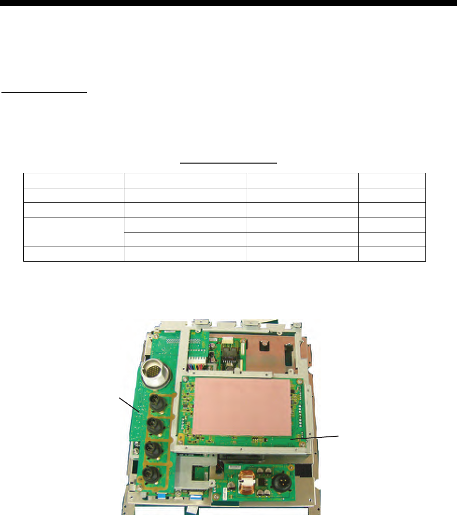
1. Unscrew all connector nuts at the rear of the display unit.
2. Unfasten all screws to remove the display cover.
03P9413
03P9415
Removing the display unit cover
3. Disconnect the printed circuit board 03P9415 and 03P9413.
Before disconnecting the 03P9413, disconnect J601 and J604 at the back of the board.
4. OPTIONAL EQUIPMENT
4-2
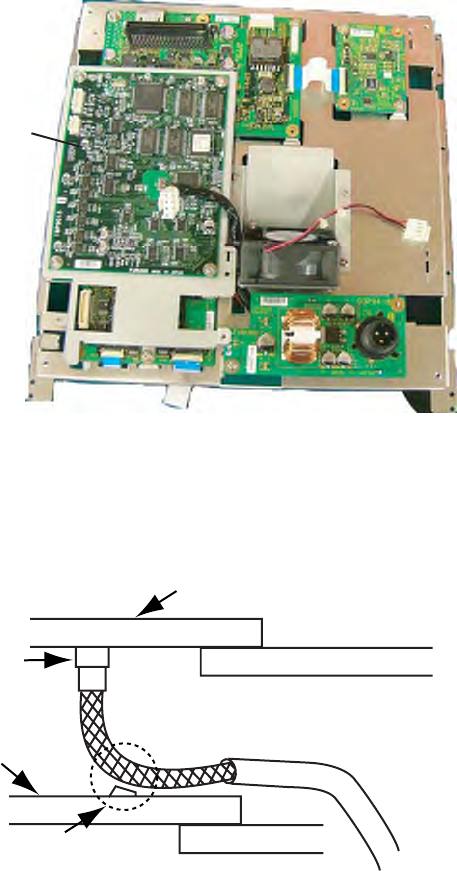
4. Mount the ARP board, mating with connectors and fixing it with four screws at the
location as shown in the figure below.
ARP board
5. Remount 03P9415 and 03P9413 at original position and display cover.
Note: After connecting the harness to J601 on 03P9413, bend the harness so that it does
not touch the parts on ARP board.
J601
ARP board
03P9413
Shall not touch.
4. OPTIONAL EQUIPMENT
4-3
4.2 External Monitor
You can display the radar image on an external monitor which accepts industrial standard
VGA input using the optional RGB kit OP03-195. Supply monitor and interconnection cable
(with HD-15P connectors of male, three rows of 15 pins) locally.
Necessary parts for external monitor
Name: RGB kit
Type: OP03-195
Code No.: 008-553-110
Name Type Code No. Qty
RGB board 03P9492 008-553-680 1
Flat cable SML2SC34-4X50BDP.5S4 000-155-457 1
Cable assy 15SDS/XHP10-005 000-144-511 1
EMI core RFC-6 000-144-132-10 1
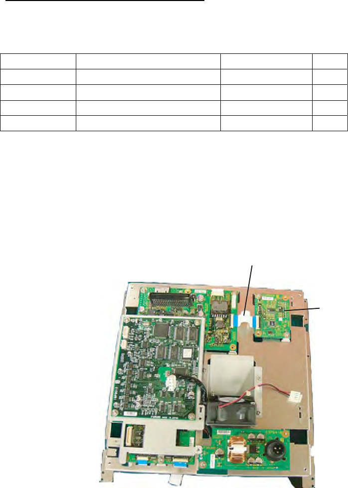
1. Unscrew all connector nuts at the rear of the display unit.
2. Unfasten all screws to remove the display cover.
3. Disconnect the printed circuit board 03P9415 and 03P9413.
Before disconnecting the 03P9413, disconnect J601 and J604 at the back of the board.
4. Mount the RGB board with two screws and connect the flat cable at the location shown
in the figure below.
Flat cable
RGB board
5. Remount 03P9415 and 03P9413 at their original locations and display cover.
4. OPTIONAL EQUIPMENT
4-4
6. Detach LCD panel from the above assembly. Be sure to disconnect the connector and
flat cables.
7. Connect the cable assy. 15SDS/XHP10-005 to the rear side of the RGB board.
8. Fix the shield wire of the cable assy. with a screw used to fix the RGB board.
9. Attach the EMI core RFC-1 to the cable assy. closely to the connector.
10. Pass the signal cable through the hole shown below and then pass it through the
“OPTION” port at the rear of the display unit..
RGB board (opposite side)
Fix shield wire with
a RGB board fixing bolt.
Attach EMI core closely
to the connector.
RGB cable assy.
Pass cable through here.
11. Reassemble the display unit and cover the hole with soft putty to seal.
12. Fix the EMI core RFC-6 to the cable closely to the display unit.
4. OPTIONAL EQUIPMENT
4-5
4.3 Remote Display
The FURUNO Display Unit FMD-811, MODEL1832 or GD-280/380, etc. can be connected
to this radar as a sub display. The display unit RDP-150 also can be used as a sub display.
To interconnect them, use optional cable MJ-B24LPF0008-100/200/300 (see page iv). Also,
the EMI core (option) should be attached to the remote display cable to prevent noise.
Installation materials for remote display (Type: CP03-31001、Code number: 008-556-830)
Name Type Code no. Qty
1 EMI core RFC-H13 000-146-570-10 1
2 Cable clamp CK-13H 000-102-947-10 1
3 Cable-tie CV-100N 000-162-167-10 2
4 Cable-tie CV-150N 000-162-186-10 1
1. Unscrew all connector nuts at the rear of the main display unit.
2. Unfasten all screws to remove the display cover.
3. Pass the signal cable from the “OPTION” port at the rear of the display unit through the
hole shown in the figure below and then connect it to the SPU board.
4. Fix the shield wire with a screw used to fixed the SPU board.
5. Attach the EMI core RFC-H13 on the signal cable.
6. Attach cable clamp and fix the cable as shown below.
90 mm
EMI core
RFC-H13
Attach cable-tie approx. 90 mm from the end of
cable and attach EMI core.
Remote display cable
Fix the EMI core with cable-tie CV-100.
Cable clamp
4. OPTIONAL EQUIPMENT
4-6
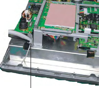
7. Fix the signal cable to the spacer of the FIL board with a cable tie CV-150N.
Fix the cable to the spacer of FIL board
with cable-tie.
8. Reassemble the display unit.
4. OPTIONAL EQUIPMENT
4-7
4.4 External Buzzer
The optional external buzzer provides a louder alert when an alarm is violated.
External buzzer
Type: OP03-136
Code no.: 000-086-443
Further, you need the optional cable assy. MJ-A7SPF0007-050C (w/7P connector, 5 m,
code no. 000-154-028-10).
1. Attach the MJ-A7SPF0007-050C cable assy. (option) to the PC/EXT-BUZZER port at the
rear of the display unit.
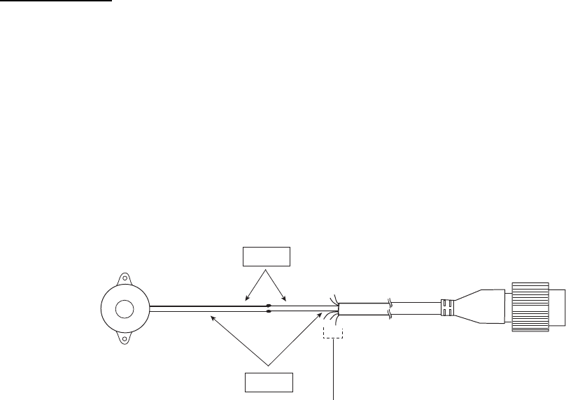
2. Cut off the XH connector and cable itself (as necessary) at the end of the external
buzzer cable.
3. Solder the cables made at step 2 to the MJ-A7SPF0007-050C cable as shown below.
Red
Black
External buzzer MJ-A7SPF0007-050C
Soldering
Other wires should be cut off,
and wrap here with vinyl tape.
Connection of external buzzer and display unit
using cable assy. type MJ-A7SPF0007-050C cable
4. Attach the buzzer to the mounting location with double-sided tape or two self-tapping
screws (3x15 or 3x20, local supply).
4. OPTIONAL EQUIPMENT
4-8
This page is intentionally left blank.
0#/' 176.+0' 36;&'5%4+26+10%1&'ͳ
㧼㧭㧯㧷㧵㧺㧳ޓ㧸㧵㧿㨀
)6:
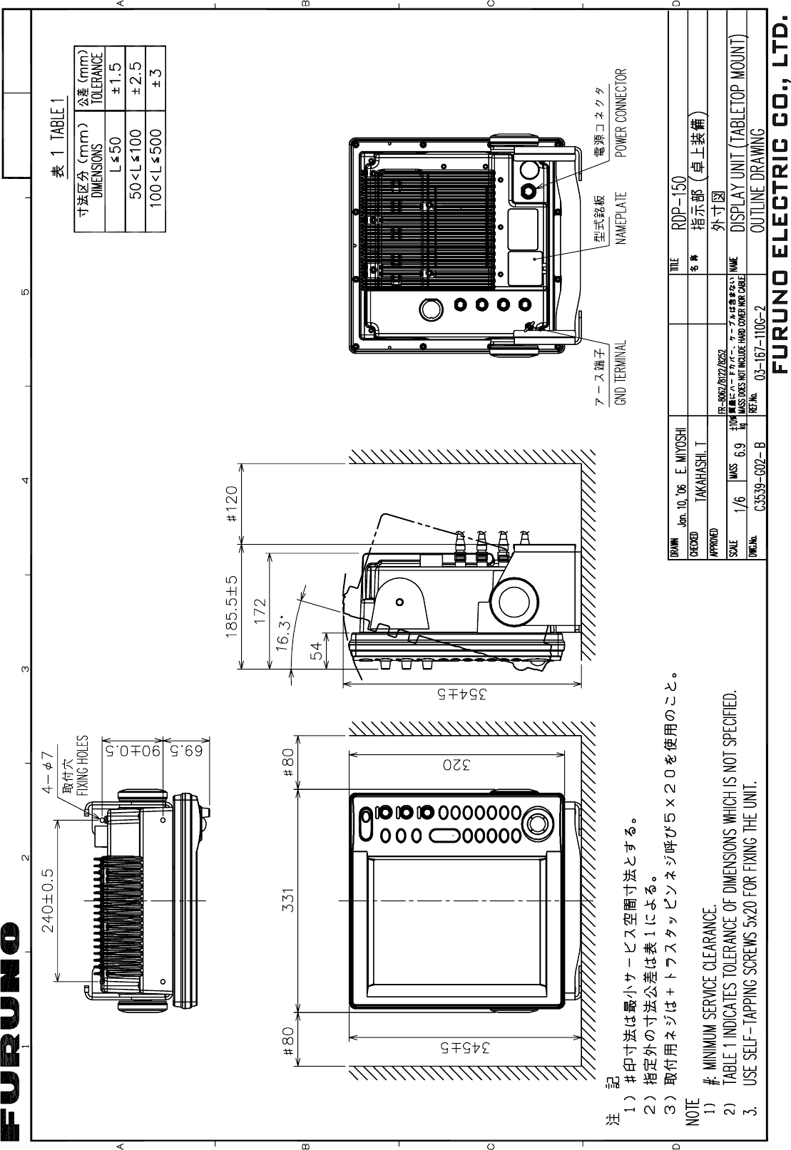
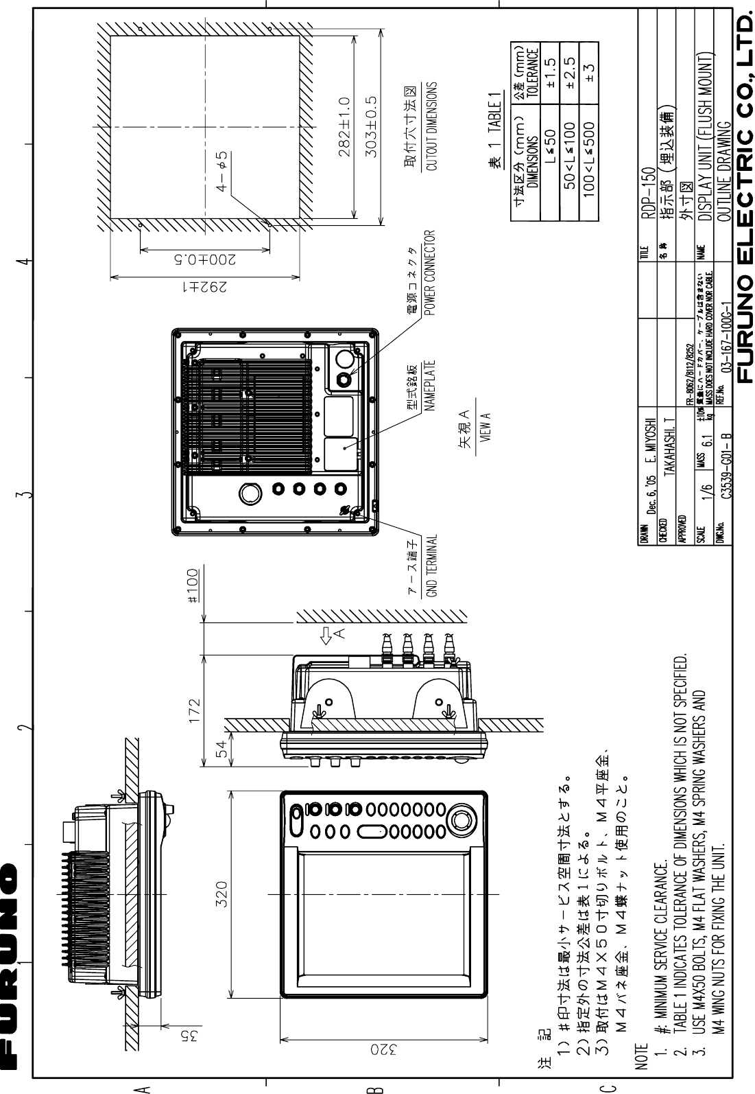
4&2,'
0#/' 176.+0' 36;&'5%4+26+10%1&'ͳ
࡙࠾࠶࠻ 70+6
ᜰ␜ㇱ
&+52.#;70+6
4&2,'
੍ຠ 52#4'2#465
੍ຠ
52#4'2#465
52
Ꮏ᧚ᢱ +056#..#6+10/#6'4+#.5
%2
Ꮏ᧚ᢱ
+056#..#6+10/#6'4+#.5
%2
Ꮏ᧚ᢱ
+056#..#6+10/#6'4+#.5
%2
㩃㨺㩖㩨㩣⚵ຠ/,
%#$.'#55;
/,#52(<%
࿑ᦠ &1%7/'06
㩖㩡㨹㩆㨷㩙㨽㩧㩎㩠㨽ဳ⚕
(.75*/1706+0)6'/2.#6'
%
ᛛㆡ⸽ⷐ㗔
#22.+%#6+10)7+&'
㩿㪁㪈㪀
,
㩕㨷㨺㩇㩨ᄌᦝߩ߅㗿
016+%'(14(75'
4'2.#%'/'06
%
ขᛒ⺑ᦠ
12'4#6145/#07#.
1/
ᠲⷐ㗔ᦠ
12'4#6145)7+&'
15
ⵝⷐ㗔ᦠ
+056#..#6+10/#07#.
+/
䍘㪄䍢䍼⇟ภᧃየ䈱㪲㪁㪁㪴䈲䇮ㆬᛯຠ䈱ઍ䍘䍎䍢䍼䉕䈚䉁䈜䇯
㪚㪦㪛㪜㩷㪥㪬㪤㪙㪜㪩㩷㪜㪥㪛㪠㪥㪞㩷㪮㪠㪫㪟㩷㩹㪁㪁㩹㩷㪠㪥㪛㪠㪚㪘㪫㪜㪪㩷㪫㪟㪜㩷㪚㪦㪛㪜㩷㪥㪬㪤㪙㪜㪩㩷㪦㪝㩷㪩㪜㪧㪩㪜㪪㪜㪥㪫㪘㪫㪠㪭㪜㩷㪤㪘㪫㪜㪩㪠㪘㪣㪅
㩿㪁㪈㪀䈱ᦠ㘃䈲䇮ᢥ᭽ኾ↪
㩿㪁㪈㪀㩷㪤㪘㪩㪢㪜㪛㩷㪛㪦㪚㪬㪤㪜㪥㪫㪪㩷㪘㪩㪜㩷㪝㪦㪩㩷㪡㪘㪧㪘㪥㪜㪪㪜㩷㪪㪜㪫㩷㪦㪥㪣㪰㪅
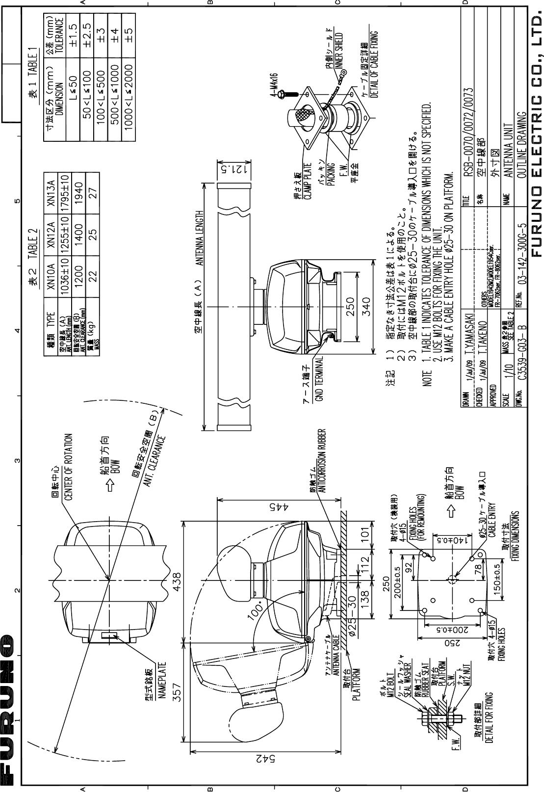
䯴⇛࿑䬽ኸᴺ䬾䫺ෳ⠨୯䬶䬨䫻䎃䎧䎬䎰䎨䎱䎶䎬䎲䎱䎶䎃䎬䎱䎃䎧䎵䎤䎺䎬䎱䎪䎃䎩䎲䎵䎃䎵䎨䎩䎨䎵䎨䎱䎦䎨䎃䎲䎱䎯䎼䎑䯵
)6:
ဳᑼ䎒䱤䱚䱮䲈⇟ภ䬛䯾Ბ䬽႐ว䫺ਅᲑ䭗䭙Ბ䬺ઍ䭞䭚ㆊᷰᦼຠ䬶䬑䭙䫺䬸䬰䭘䬚䬛䬲䬵䬓䭍䬨䫻䫹䬹䬙䫺ຠ⾰䬾ᄌ䭞䭙䭍䬪䭢䫻
䎷䎺䎲䎃䎷䎼䎳䎨䎶䎃䎤䎱䎧䎃䎦䎲䎧䎨䎶䎃䎰䎤䎼䎃䎥䎨䎃䎯䎬䎶䎷䎨䎧䎃䎩䎲䎵䎃䎤䎱䎃䎬䎷䎨䎰䎑䎃䎃䎷䎫䎨䎃䎯䎲䎺䎨䎵䎃䎳䎵䎲䎧䎸䎦䎷䎃䎰䎤䎼䎃䎥䎨䎃䎶䎫䎬䎳䎳䎨䎧䎃䎬䎱䎃䎳䎯䎤䎦䎨䎃䎲䎩䎃
䎷䎫䎨䎃䎸䎳䎳䎨䎵䎃䎳䎵䎲䎧䎸䎦䎷䎑䎃䎴䎸䎤䎯䎬䎷䎼䎃䎬䎶䎃䎷䎫䎨䎃䎶䎤䎰䎨䎑
A
-1
㧼㧭㧯㧷㧵㧺㧳ޓ㧸㧵㧿㨀
#-:
:0#:0#:0#:0#0%-&:0#0%-&
0#/' 176.+0' &'5%4+26+10%1&'ͳ 36;
࡙࠾࠶࠻ 70+6
㨻㩧㩍㩏
#06'00#
:0###
㨻㩧㩍㩏Ꮏ᧚ #06'00#+056#..#6+10/#6'4+#.5
Ꮏ᧚ᢱ
+056#..#6+10/#6'4+#.5
%2
䍘㪄䍢䍼⇟ภᧃየ䈱㪲㪁㪁㪴䈲䇮ㆬᛯຠ䈱ઍ䍘䍎䍢䍼䉕䈚䉁䈜䇯
㪚㪦㪛㪜㩷㪥㪬㪤㪙㪜㪩㩷㪜㪥㪛㪠㪥㪞㩷㪮㪠㪫㪟㩷㩹㪁㪁㩹㩷㪠㪥㪛㪠㪚㪘㪫㪜㪪㩷㪫㪟㪜㩷㪚㪦㪛㪜㩷㪥㪬㪤㪙㪜㪩㩷㪦㪝㩷㪩㪜㪧㪩㪜㪪㪜㪥㪫㪘㪫㪠㪭㪜㩷㪤㪘㪫㪜㪩㪠㪘㪣㪅
䋨⇛࿑䈱ኸᴺ䈲䇮ෳ⠨୯䈪䈜䇯㩷㩷㪛㪠㪤㪜㪥㪪㪠㪦㪥㪪㩷㪠㪥㩷㪛㪩㪘㪮㪠㪥㪞㩷㪝㪦㪩㩷㪩㪜㪝㪜㪩㪜㪥㪚㪜㩷㪦㪥㪣㪰㪅䋩
#-:
ဳᑼ㪆䍘䍎䍢䍼⇟ภ䈏䋲Ბ䈱႐ว䇮ਅᲑ䉋䉍Ბ䈮ઍ䉒䉎ㆊᷰᦼຠ䈪䈅䉍䇮䈬䈤䉌䈎䈏䈦䈩䈇䉁䈜䇯䇭䈭䈍䇮ຠ⾰䈲ᄌ䉒䉍䉁䈞䉖䇯
㪫㪮㪦㩷㪫㪰㪧㪜㪪㩷㪘㪥㪛㩷㪚㪦㪛㪜㪪㩷㪤㪘㪰㩷㪙㪜㩷㪣㪠㪪㪫㪜㪛㩷㪝㪦㪩㩷㪘㪥㩷㪠㪫㪜㪤㪅㩷㩷㪫㪟㪜㩷㪣㪦㪮㪜㪩㩷㪧㪩㪦㪛㪬㪚㪫㩷㪤㪘㪰㩷㪙㪜㩷㪪㪟㪠㪧㪧㪜㪛㩷㪠㪥㩷㪧㪣㪘㪚㪜㩷㪦㪝㩷㪫㪟㪜㩷㪬㪧㪧㪜㪩㩷
㪧㪩㪦㪛㪬㪚㪫㪅㩷㪨㪬㪘㪣㪠㪫㪰㩷㪠㪪㩷㪫㪟㪜㩷㪪㪘㪤㪜㪅
A
-3
㧼㧭㧯㧷㧵㧺㧳ޓ㧸㧵㧿㨀
)6:
45$45$45$45$
0#/' 176.+0' &'5%4+26+10%1&'ͳ 36;
࡙࠾࠶࠻ 70+6
ⓨਛ✢ᧄㇱ
#06'00#70+6
45$
Ꮏ᧚ᢱ +056#..#6+10/#6'4+#.5
ⓨਛ✢ㇱᎿ᧚
#06'00#+056#..#6+10/#6'4+#.5
%2
䍘㪄䍢䍼⇟ภᧃየ䈱㪲㪁㪁㪴䈲䇮ㆬᛯຠ䈱ઍ䍘䍎䍢䍼䉕䈚䉁䈜䇯
㪚㪦㪛㪜㩷㪥㪬㪤㪙㪜㪩㩷㪜㪥㪛㪠㪥㪞㩷㪮㪠㪫㪟㩷㩹㪁㪁㩹㩷㪠㪥㪛㪠㪚㪘㪫㪜㪪㩷㪫㪟㪜㩷㪚㪦㪛㪜㩷㪥㪬㪤㪙㪜㪩㩷㪦㪝㩷㪩㪜㪧㪩㪜㪪㪜㪥㪫㪘㪫㪠㪭㪜㩷㪤㪘㪫㪜㪩㪠㪘㪣㪅
㧔⇛࿑ߩኸᴺߪޔෳ⠨୯ߢߔޕ&+/'05+105+0&4#9+0)(144'('4'0%'10.;㧕
)6:
A
-2
%1&'01
6;2'
%2
⇛ޓޓ࿑
176.+0'
ฬޓޓ⒓
0#/'
ᢙ㊂
36;
↪ㅜ㧛⠨
4'/#4-5
⇟ภ
01
ဳฬ㧛ⷙᩰ
&'5%4+26+105
+056#..#6+10/#6'4+#.5
Ꮏ᧚ᢱ
)6:
㩔㩨㩒ᐳ㊄
524+0)9#5*'4 /575
%1&'01
㩚㩀㩨㩁ᐔᐳ㊄
(.#69#5*'4 /575
%1&'01
ⷺ㩏㨹㩎㩆㨷
*':#)10#.076 /575
%1&'01
ⷺ㩘㩨㩣㩎
*':#)10#.*'#&$1.6 /:575
%1&'01
'/+㩄㨻
'/+%14' 4(%
%1&'01
'/+㩄㨻
'/+%14' 4(%*
%1&'01
㩃㨺㩖㩨㩣⚵ຠ
%#$.'#55; 49
%1&'01
49
㧔⇛࿑ߩኸᴺߪޔෳ⠨୯ߢߔޕޓ&+/'05+105+0&4#9+0)(144'('4'0%'10.;㧕
㧲㨁㧾㨁㧺㧻ޓ㧱㧸㧱㧯㨀㧾㧵㧯ޓ㧯㧻ޓ㧚
㧘
㧸㨀㧰
)6:
ဳᑼ㩄㨺㩎㩨⇟ภ߇㧞Ბߩ႐วޔਅᲑࠃࠅᲑߦઍࠊࠆㆊᷰᦼຠߢࠅޔߤߜࠄ߆߇ߞߡ߹ߔޕޓߥ߅ޔຠ⾰ߪᄌࠊࠅ߹ߖࠎޕ
6916;2'5#0&%1&'5/#;$'.+56'&(14#0+6'/6*'.19'4241&7%6/#;$'5*+22'&+02.#%'1(6*'722'4241&7%6
37#.+6;+56*'5#/'
A
-5
%1&'01
6;2'
%2
⇛ޓޓ࿑
176.+0'
ฬޓޓ⒓
0#/'
ᢙ㊂
36;
↪ㅜ㧛⠨
4'/#4-5
⇟ภ
01
ဳฬ㧛ⷙᩰ
&'5%4+26+105
+056#..#6+10/#6'4+#.5
Ꮏ᧚ᢱ
)6:
㩆㨺㩣㩦㨹㩆㨶㨺
5'#.9#5*'4 41*5
%1&'01
㒐ⲁࠧࡓ
%14415+102411(
47$$'4/#6
41*5
%1&'01
㩔㩩㨹㩁㩧㨿㩅㨾
2#%-+0)(+:674' 41*5
%1&'01
㩆㨺㩣㩎㩨㩂㩡㩧㩖㩩
5*+'.&%.#/2 41*5
%1&'01
㩁㨶㨹㩖㩩
-01$%#2
%1&'01
㩚㩀㩨㩁㩙㩣ᐔᐳ㊄
(.#69#5*'4 /575
%1&'01
ⷺ㩏㨹㩎㩆㨷
*':#)10#.076 /575
%1&'01
㩔㩨㩒ᐳ㊄
524+0)9#5*'4 /575
%1&'01
ⷺ㩘㩨㩣㩎ో㩒㩆㩨
*':#)10*'#&5%4'9 /:575
%1&'01
㩏㩗㩨㩈㩛㩇$
9#5*'4*'#&5%4'9$ /:%9/$0+
%1&'01
㧔⇛࿑ߩኸᴺߪޔෳ⠨୯ߢߔޕޓ&+/'05+105+0&4#9+0)(144'('4'0%'10.;㧕
㧲㨁㧾㨁㧺㧻ޓ㧱㧸㧱㧯㨀㧾㧵㧯ޓ㧯㧻ޓ㧚
㧘
㧸㨀㧰
)6:
ဳᑼ㩄㨺㩎㩨⇟ภ߇㧞Ბߩ႐วޔਅᲑࠃࠅᲑߦઍࠊࠆㆊᷰᦼຠߢࠅޔߤߜࠄ߆߇ߞߡ߹ߔޕޓߥ߅ޔຠ⾰ߪᄌࠊࠅ߹ߖࠎޕ
6916;2'5#0&%1&'5/#;$'.+56'&(14#0+6'/6*'.19'4241&7%6/#;$'5*+22'&+02.#%'1(6*'722'4241&7%6
37#.+6;+56*'5#/'
A
-4
%1&'01
6;2'
%2
⇛ޓޓ࿑
176.+0'
ฬޓޓ⒓
0#/'
ᢙ㊂
36;
↪ㅜ㧛⠨
4'/#4-5
⇟ภ
01
ဳฬ㧛ⷙᩰ
&'5%4+26+105
+056#..#6+10/#6'4+#.5
Ꮏ᧚ᢱ
)6:
(㩙㨽㩧㩎㩠㨽㩇㩘㩩㩧㩆㩨
(.75*/1706+0)5210)' 41*5
%1&'01
㧔⇛࿑ߩኸᴺߪޔෳ⠨୯ߢߔޕޓ&+/'05+105+0&4#9+0)(144'('4'0%'10.;㧕
㧲㨁㧾㨁㧺㧻ޓ㧱㧸㧱㧯㨀㧾㧵㧯ޓ㧯㧻ޓ㧚
㧘
㧸㨀㧰
)6:
ဳᑼ㩄㨺㩎㩨⇟ภ߇㧞Ბߩ႐วޔਅᲑࠃࠅᲑߦઍࠊࠆㆊᷰᦼຠߢࠅޔߤߜࠄ߆߇ߞߡ߹ߔޕޓߥ߅ޔຠ⾰ߪᄌࠊࠅ߹ߖࠎޕ
6916;2'5#0&%1&'5/#;$'.+56'&(14#0+6'/6*'.19'4241&7%6/#;$'5*+22'&+02.#%'1(6*'722'4241&7%6
37#.+6;+56*'5#/'
A
-7
%1&'01
6;2'
%2
⇛ޓޓ࿑
176.+0'
ฬޓޓ⒓
0#/'
ᢙ㊂
36;
↪ㅜ㧛⠨
4'/#4-5
⇟ภ
01
ဳฬ㧛ⷙᩰ
&'5%4+26+105
+056#..#6+10/#6'4+#.5
Ꮏ᧚ᢱ
)6:
㒐ᝄ㩄㩨㩛
47$$'4%75*+10
%1&'
01
㒐ᝄ㩄㩨㩛
47$$'4%75*+10
%1&'
01
㩎㩡㩇㩊㨹㩕㩩㩧㩒㩆㩨ޓ㩆㨷
5'.(6#22+0)5%4'9 :575
%1&'
01
㩔㩨㩒ᐳ㊄
524+0)9#5*'4 /575
%1&'
01
㩚㩀㩨㩁ਣᐔᐳ㊄
(.#69#5*'4 /575
%1&'
01
಄㑆ㅧⲔ㩏㨹㩎
9+0)076 /575
%1&'
01
ኸಾ㩘㩨㩣㩎
6*4'#&'&41& /:575
%1&'
01
㧔⇛࿑ߩኸᴺߪޔෳ⠨୯ߢߔޕޓ&+/'05+105+0&4#9+0)(144'('4'0%'10.;㧕
㧲㨁㧾㨁㧺㧻ޓ㧱㧸㧱㧯㨀㧾㧵㧯ޓ㧯㧻ޓ㧚
㧘
㧸㨀㧰
)6:
ဳᑼ㩄㨺㩎㩨⇟ภ߇㧞Ბߩ႐วޔਅᲑࠃࠅᲑߦઍࠊࠆㆊᷰᦼຠߢࠅޔߤߜࠄ߆߇ߞߡ߹ߔޕޓߥ߅ޔຠ⾰ߪᄌࠊࠅ߹ߖ
ࠎޕ
6916;2'5#0&%1&'5/#;$'.+56'&(14#0+6'/6*'.19'4241&7%6/#;$'5*+22'&+02.#%'1(6*'722'4
241&7%637#.+6;+56*'5#/'
A
-6
%1&'01
6;2'
⇛ޓޓ࿑
176.+0'
ฬޓޓ⒓
0#/'
ᢙ㊂
36;
↪ㅜ㧛⠨
4'/#4-5
⇟ภ
01
ဳฬ㧛ⷙᩰ
&'5%4+26+105
+056#..#6+10/#6'4+#.5
Ꮏ᧚ᢱ
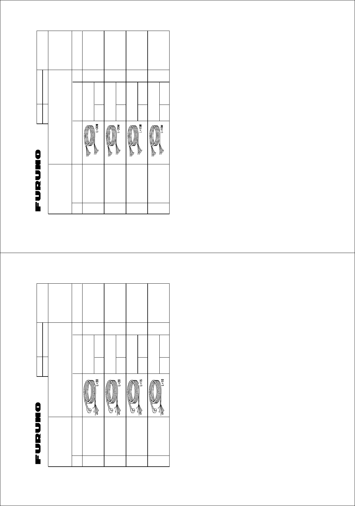
(4
#8:
㩃㨺㩖㩨㩣⚵ຠ
%#$.'#55;
49/
ㆬᛯޓޓޓޓޓޓޓޓ
61$'5'.'%6'&
%1&'01
㩃㨺㩖㩨㩣⚵ຠ
%#$.'#55;
49/
ㆬᛯޓޓޓޓޓޓޓޓ
61$'5'.'%6'&
%1&'01
㩃㨺㩖㩨㩣⚵ຠ
%#$.'#55;
49/
ㆬᛯޓޓޓޓޓޓޓޓ
61$'5'.'%6'&
%1&'01
㩃㨺㩖㩨㩣⚵ຠ
%#$.'#55;
49/
ㆬᛯޓޓޓޓޓޓޓޓ
61$'5'.'%6'&
%1&'01
㧔⇛࿑ߩኸᴺߪޔෳ⠨୯ߢߔޕޓ&+/'05+105+0&4#9+0)(144'('4'0%'10.;㧕
㧲㨁㧾㨁㧺㧻ޓ㧱㧸㧱㧯㨀㧾㧵㧯ޓ㧯㧻ޓ㧚㧘㧸㨀㧰
#8:
A
-9
%1&'01
6;2'
⇛ޓޓ࿑
176.+0'
ฬޓޓ⒓
0#/'
ᢙ㊂
36;
↪ㅜ㧛⠨
4'/#4-5
⇟ภ
01
ဳฬ㧛ⷙᩰ
&'5%4+26+105
+056#..#6+10/#6'4+#.5
Ꮏ᧚ᢱ
(4
)6:
㩃㨺㩖㩨㩣⚵ຠ/,
%#$.'#55;
/,$.2(
ㆬᛯޓޓޓޓޓޓޓޓ
61$'5'.'%6
%1&'01
㩃㨺㩖㩨㩣⚵ຠ/,
%#$.'#55;
/,$.2(
ㆬᛯޓޓޓޓޓޓޓޓ
61$'5'.'%6
%1&'01
㩃㨺㩖㩨㩣⚵ຠ/,
%#$.'#55;
/,$.2(
ㆬᛯޓޓޓޓޓޓޓޓ
61$'5'.'%6
%1&'01
㩃㨺㩖㩨㩣⚵ຠ/,
%#$.'#55;
/,$.2(
ㆬᛯޓޓޓޓޓޓޓޓ
61$'5'.'%6
%1&'01
㧔⇛࿑ߩኸᴺߪޔෳ⠨୯ߢߔޕޓ&+/'05+105+0&4#9+0)(144'('4'0%'10.;㧕
㧲㨁㧾㨁㧺㧻ޓ㧱㧸㧱㧯㨀㧾㧵㧯ޓ㧯㧻ޓ㧚㧘㧸㨀㧰
)6:
A
-8
%1&'01
6;2'
%2
⇛ޓޓ࿑
176.+0'
ฬޓޓ⒓
0#/'
ᢙ㊂
36;
↪ㅜ㧛⠨
4'/#4-5
⇟ภ
01
ဳฬ㧛ⷙᩰ
&'5%4+26+105
+056#..#6+10/#6'4+#.5
Ꮏ᧚ᢱ
#8:
㩎㩡㩇㩊㨹㩕㩩㩧㩒㩆㩨ޓ㩆㨷
5'.(6#22+0)5%4'9 :575
%1&'
01
㩄㩒㩂㩊⚵ຠ
%100'%614#55; :*2.#%4
%1&'
01
㧔⇛࿑ߩኸᴺߪޔෳ⠨୯ߢߔޕޓ&+/'05+105+0&4#9+0)(144'('4'0%'10.;㧕
㧲㨁㧾㨁㧺㧻ޓ㧱㧸㧱㧯㨀㧾㧵㧯ޓ㧯㧻ޓ㧚
㧘
㧸㨀㧰
#8:
ဳᑼ㩄㨺㩎㩨⇟ภ߇㧞Ბߩ႐วޔਅᲑࠃࠅᲑߦઍࠊࠆㆊᷰᦼຠߢࠅޔߤߜࠄ߆߇ߞߡ߹ߔޕޓߥ߅ޔຠ⾰ߪᄌࠊࠅ߹ߖ
ࠎޕ
6916;2'5#0&%1&'5/#;$'.+56'&(14#0+6'/6*'.19'4241&7%6/#;$'5*+22'&+02.#%'1(6*'722'4
241&7%637#.+6;+56*'5#/'
A
-11
㧼㧭㧯㧷㧵㧺㧳ޓ㧸㧵㧿㨀
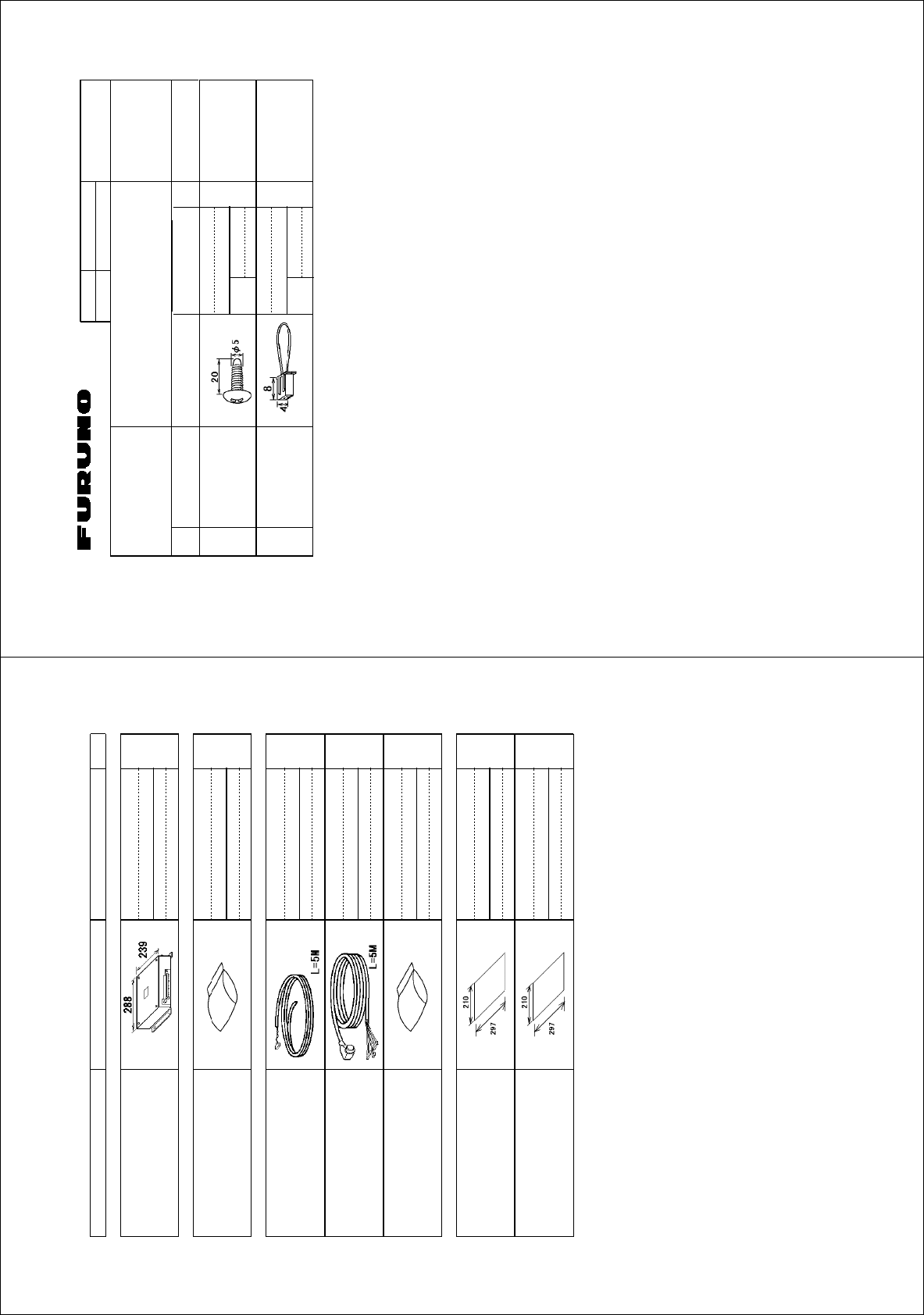
#8:
257
0#/' 176.+0' &'5%4+26+10%1&'ͳ 36;
࡙࠾࠶࠻ 70+6
ⓨਛ✢㔚Ḯㇱ
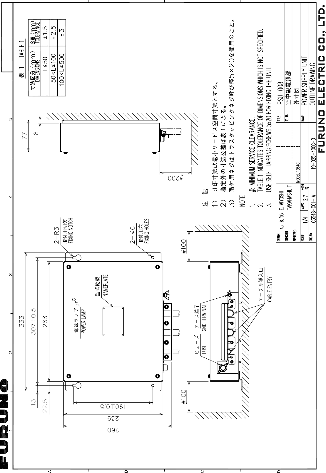
219'45722.;70+6
257
੍ຠ 52#4'2#465
੍ຠ
52#4'2#465
52
Ꮏ᧚ᢱ +056#..#6+10/#6'4+#.5 %2
㩃㨺㩖㩨㩣㩂㩚㩕㩧
%#$.'#55'/$.;
8.2885:%##
㩃㨺㩖㩨㩣⚵ຠ/,
5+)0#.%#$.'#55'/$.;
/,$.2(4
Ꮏ᧚ᢱ
+056#..#6+10/#6'4+#.5
%2
࿑ᦠ &1%7/'06
㩕㨷㨺㩇㩨ᄌᦝߩ߅㗿
016+(+%#6+10&1%7/'06
%
⸳ቯⷐ㗔ᦠ
+06'40#.5'66+0),4'0
%
䋨⇛࿑䈱ኸᴺ䈲䇮ෳ⠨୯䈪䈜䇯㩷㩷㪛㪠㪤㪜㪥㪪㪠㪦㪥㪪㩷㪠㪥㩷㪛㪩㪘㪮㪠㪥㪞㩷㪝㪦㪩㩷㪩㪜㪝㪜㪩㪜㪥㪚㪜㩷㪦㪥㪣㪰㪅䋩
#8:
ဳᑼ㪆䍘䍎䍢䍼⇟ภ䈏䋲Ბ䈱႐ว䇮ਅᲑ䉋䉍Ბ䈮ઍ䉒䉎ㆊᷰᦼຠ䈪䈅䉍䇮䈬䈤䉌䈎䈏䈦䈩䈇䉁䈜䇯䇭䈭䈍䇮ຠ⾰䈲ᄌ䉒䉍䉁䈞䉖䇯
㪫㪮㪦㩷㪫㪰㪧㪜㪪㩷㪘㪥㪛㩷㪚㪦㪛㪜㪪㩷㪤㪘㪰㩷㪙㪜㩷㪣㪠㪪㪫㪜㪛㩷㪝㪦㪩㩷㪘㪥㩷㪠㪫㪜㪤㪅㩷㩷㪫㪟㪜㩷㪣㪦㪮㪜㪩㩷㪧㪩㪦㪛㪬㪚㪫㩷㪤㪘㪰㩷㪙㪜㩷㪪㪟㪠㪧㪧㪜㪛㩷㪠㪥㩷㪧㪣㪘㪚㪜㩷㪦㪝㩷㪫㪟㪜㩷㪬㪧㪧㪜㪩㩷
㪧㪩㪦㪛㪬㪚㪫㪅㩷㪨㪬㪘㪣㪠㪫㪰㩷㪠㪪㩷㪫㪟㪜㩷㪪㪘㪤㪜㪅
A
-10
%1&'01
6;2'
52
+6'/
01
0#/'1(
2#46 176.+0'
&9)01
14
2'4
5'6
2'4
8'5
52#4'
914-+0)
37#06+6; 4'/#4-5%1&'01
$1:012
5*+201
52#4'2#465.+56(14 75'
5'652'4
8'55'.
6;2'01
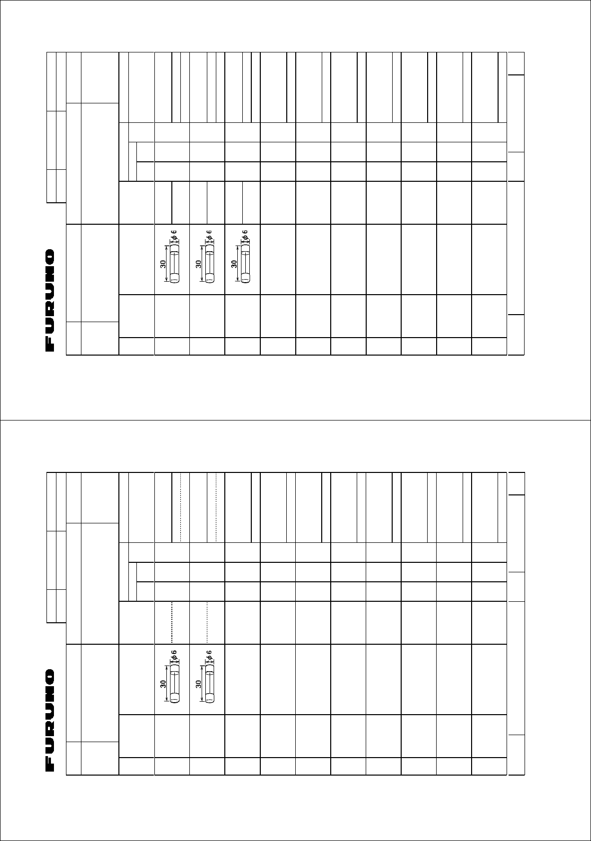
#3:
㩕㨷㨺㩇㩨
()$1#
#%8
(75'
()$8
#2$(
㩕㨷㨺㩇㩨
()$1##%8
(75'
()$8#
2$(
㩀㩧㨼㩢㩕㨷㨺㩇㩨
()$1##%8
(75'
()$18#
2$(
/(450#/'
(74701'.'%64+%%1.6&
&9)01
㧔⇛࿑ߩኸᴺߪޔෳ⠨୯ߢߔޕޓ&+/'05+105+0&4#9+0)ޓ(144'('4'0%'10.;㧕
#3:
ဳᑼ㩄㨺㩎㩨⇟ภ߇㧞Ბߩ႐วޔਅᲑࠃࠅᲑߦઍࠊࠆㆊᷰᦼຠߢࠅޔߤߜࠄ߆߇ߞߡ߹ߔޕޓߥ߅ޔຠ⾰ߪ
ᄌ
ࠊࠅ߹ߖࠎޕ
6916;2'5#0&%1&'5/#;$'.+56'&(14#0+6'/6*'.19'4241&7%6/#;$'5*+22'&+02.#%'1(6*'
722'4241&7%637#.+6;+56*'5#/'
A
-13
%1&'01
6;2'
52
+6'/
01
0#/'1(
2#46 176.+0'
&9)01
14
2'4
5'6
2'4
8'5
52#4'
914-+0)
37#06+6; 4'/#4-5%1&'01
$1:012
5*+201
52#4'2#465.+56(14 75'
5'652'4
8'55'.
6;2'01
)6:
㩕㨷㨺㩇㩨
()$1#
#%8
(75'
()$8
#2$(
㩕㨷㨺㩇㩨
()$1#
#%8
(75'
()$8
#2$(
/(450#/'
(74701'.'%64+%%1.6&
&9)01
㧔⇛࿑ߩኸᴺߪޔෳ⠨୯ߢߔޕޓ&+/'05+105+0&4#9+0)ޓ(144'('4'0%'10.;㧕
)6:
ဳᑼ㩄㨺㩎㩨⇟ภ߇㧞Ბߩ႐วޔਅᲑࠃࠅᲑߦઍࠊࠆㆊᷰᦼຠߢࠅޔߤߜࠄ߆߇ߞߡ߹ߔޕޓߥ߅ޔຠ⾰ߪ
ᄌ
ࠊࠅ߹ߖࠎޕ
6916;2'5#0&%1&'5/#;$'.+56'&(14#0+6'/6*'.19'4241&7%6/#;$'5*+22'&+02.#%'1(6*'
722'4241&7%637#.+6;+56*'5#/'
A
-12
,WN4'UWOK
D-1
Y. Hatai
D-2
Y. Hatai
D-3
Y. Hatai
D-4
Y.Hatai
D-5
A
B
C
123 4
8
7
6
5
4
3
2
1
GND
GND
GND
TRU-HD
GND
J110(NH8P)
VIDEO
PR-TRIG
DP-BP
SPU
8
7
6
5
4
3
2
1
GND
9
10
RGB 03P9429
GND
GND
GND
GND
V_SYNC
H_SYNC
B
G
R
J802 *2
SVGA MONITOR
SVGAモニター
REMOTE DISPLAY
副指示器 ミドリ
アオ
チャ
チャ(太)
シロ(太)
アカ(太)
クロ(太)
キ(太)
GRN
BLU
BRN
BRN(B)
WHT(B)
RED(B)
BLK(B)
YEL(B)
クロ
ムラサキ(太)
BLK
PPL(B)
シロ
アオ(太)
WHT
BLU(B)
ムラサキ(太)PPL(B)
L-GRN(B)キミドリ(太)
ドウジク COAX.
GRY(B)ミドリ(太)
ダイ(太)ORG(B)
モモ(太)PNK(B)
アカ
ハイ(太)GRY(B)
RED
ダイ ORG
10
11
20
14
15
2
8
7
17
15
9
1
18
22
21
16
6
13
12
19
3
4
23
24
*3
1
2
3
4
5
6
NMEA1
MJ-A7SPF
SG
RD1-C
RD1-H
TD1-B
TD1-A
7SHIELD
+12V
GRN
YEL
WHT
キ
シロ
ミドリ
BLK
クロ
アカ RED
アオ BLU
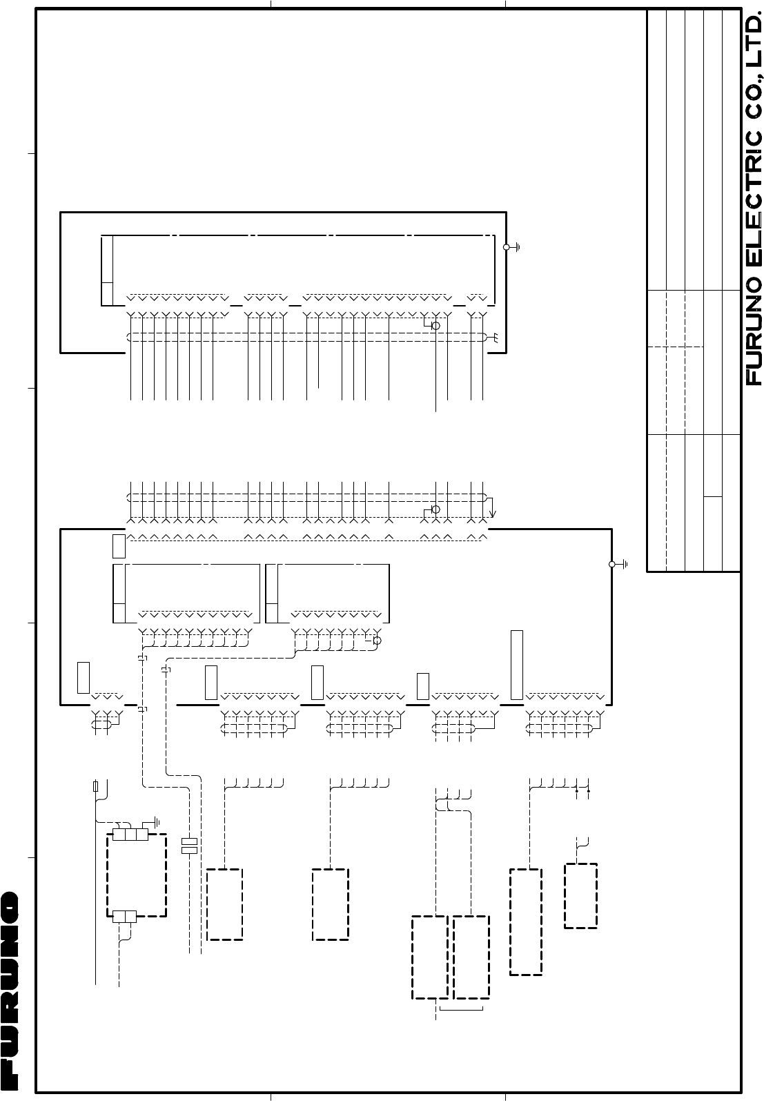
航法装置
NAV EQUIPMENT
(NMEA0183) 5m,φ7
*2
*3
1
2
3
4
5
6
MJ-A7SPF
SG
7SHIELD
+12V
GRN
YEL
WHT
キ
シロ
ミドリ
BLK
クロ
アカ RED
アオ BLU
航法装置
NAV EQUIPMENT
(NMEA0183) 5m,φ7
*2
HDG
GND
NC
CLK-C
CLK-H
DATA-C
DATA-H
キ
クロ
シロ
GRN
YEL
BLK
WHT
MJ-A6SPF
*3
1
2
3
4
5
6
ミドリ
ジャイロ
GYRO MJ-A6SPF0003-050C/100C
5/10m,φ6
A-D CONVERTER
A-Dコンバータ
AD-100
10m,φ6
MJ-A6SPF0007-100C
HEADING SENSOR
PG-1000
ヘディングセンサー
*2
*2
*2
*2
選択
SELECT
*4
(RW-9807,21C+2C2V,30m MAX.)
MJ-B24LPF0012,10/15/20/30m,φ11
8
7
6
5
4
3
2
1
9
-12V
GND
+12V
+12V
-12V
TX-TRIG.
P/L-A
P/L-B
NC
RTB 03P9405A
4
3
2
1BP
MOTOR+
HD.
MOTOR-
J821(VH9P)
J823(VH4P)
5
6
7
8
4
3
2
1
9
10
TUNE-IND.
MOTOR-
NC
MOTOR+
MBS-L
MOTOR+
NC
GND
NC
NC
11
12
13
GND
VIDEO
TUNE-CONT
J822(VH2P)
2
1-12
+12
空中線部 ANTENNA UNIT
*4
RSB-0070/0073
RDP-150
DISPLAY UNIT
指示部
シロ
クロ
WHT
BLK
15A:12V
10A:24V MJ-A3SPF
3
2
1
POWER
GND
(-)
(+)
注記
*5) EMIコアを取り付ける。
*1) 造船所手配。
*2) オプション。
*3) コネクタは工場にて取付済み。
*4) シールドは両端で完全にアースする。
NOTES
*3: FITTED AT FACTORY.
*4: GROUND SHIELD EFFECTIVELY AT BOTH ENDS.
*2: OPTION.
*1: SHIPYARD SUPPLY.
*5: ATTACH EMI CORES. kg
名称
NAME
TITLE
MASS
SCALE
APPROVED
CHECKED
DRAWN
MARINE RADAR
INTERCONNECTION DIAGRAM
船舶用レーダー
相互結線図
FR-8062/8122
T.YAMASAKI
1
2
3
4
5
6
MJ-A7SPF
7SHIELD
+12V
GRN
YEL
WHT
キ
シロ
ミドリ
BLK
クロ
アカ RED
アオ BLU
*2 PC/EXT-BUZZER
SD
RD
REMOTE-KEY
NC
EXT.BUZZER
BLK
クロ
アカ RED
5m,φ7
EXT. BUZZER
OP03-136
外部ブザー
*2
1m
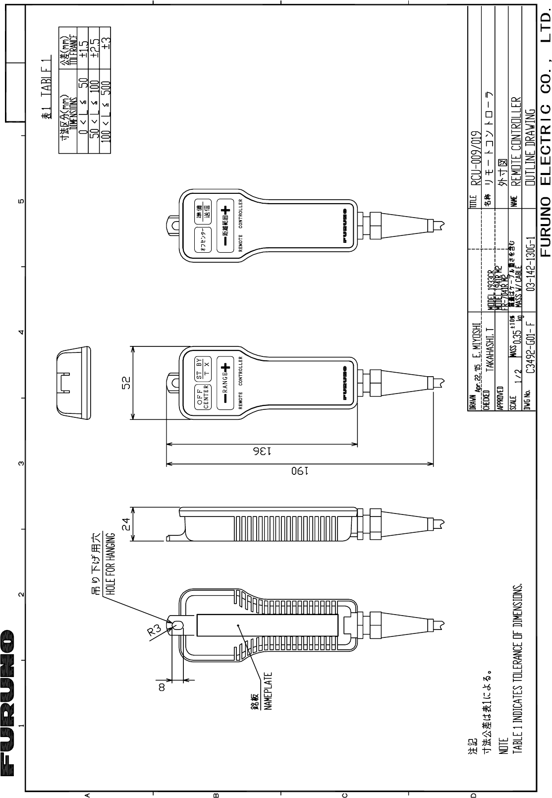
リモートコントローラ
REMOTE CONTROLLER
RCU-019 *2
DWG.No.
*3
*2
*3
TD2-A
TD2-B
RD2-H
RD2-C
RW-4747
キ YEL
IV-2sq.
*1
REF.No.
*5
*5
*5
*5
DJ-1
03P9411
J824(NH13P)
SVGA MONITOR CABLE
*1
MJ-A3SPF0018-050ZC,5m,φ10
220/230 VAC
100/110/115/
1φ,50/60Hz
3
(+)
(-) 2
24V
7
6
1
*1
IV-2sq.
PR-240
AC/DC POWER
SUPPLY UNIT
AC/DC電源
ユニット
*2
DPYC-1.5 *1
12-24 VDC
Dsub15P
10/20/30m,φ11.4
MJ-B24LPF0008
19S1004,0.5m *5*5
MJ-A7SPF0007-050C
MJ-A7SPF0007-050C
MJ-A7SPF0007-050C
NMEA2
(RTR-085A/086A)
03-167-6003-3C3539-C01- G
H.MAKI
25/Mar/2011
25/Mar/2011
S-1
12 4
3
B
A
C
FURUNO ELECTRIC CO., LTD.
*3
1
2
3
4
5
6
NMEA1
MJ-A7SPF
SG
RD1-C
RD1-H
TD1-B
TD1-A
7SHIELD
+12V
GRN
YEL
WHT
キ
シロ
ミドリ
BLK
クロ
アカ RED
アオ BLU
航法装置
NAV EQUIPMENT
(NMEA0183) 5m,φ7
*2
*3
1
2
3
4
5
6
MJ-A7SPF
SG
7SHIELD
+12V
GRN
YEL
WHT
キ
シロ
ミドリ
BLK
クロ
アカ RED
アオ BLU
航法装置
NAV EQUIPMENT
(NMEA0183) 5m,φ7
*2
HDG
GND
NC
CLK-C
CLK-H
DATA-C
DATA-H
MJ-A6SPF
*3
1
2
3
4
5
6
RDP-150
DISPLAY UNIT
指示部
1
2
3
4
5
6
MJ-A7SPF
7SHIELD
+12V
GRN
YEL
WHT
キ
シロ
ミドリ
BLK
クロ
アカ RED
アオ BLU
*2 PC/EXT-BUZZER
SD
RD
REMOTE-KEY
NC
EXT.BUZZER
BLK
クロ
アカ RED
5m,φ7
EXT. BUZZER
OP03-136
外部ブザー
*2
1m
リモートコントローラ
REMOTE CONTROLLER
RCU-019 *2
*3
TD2-A
TD2-B
RD2-H
RD2-C
*5
シロ
クロ
WHT
BLK
15A:12V
10A:24V MJ-A3SPF
3
2
1
POWER
GND
(-)
(+)
*3
MJ-A3SPF0018-050ZC
5m,φ10
12-24 VDC
*5*5
MJ-A7SPF0007-050C
MJ-A7SPF0007-050C
MJ-A7SPF0007-050C
NMEA2
(03S9801)
VL3P-VV-S2X2C-AA050,5m,φ10
10/20/30m,φ11.4
MJ-B24LPF0008
19S1004,0.5m
3
(+)
(-) 2
24V
7
6
1
IV-2sq.
PR-240
AC/DC POWER
SUPPLY UNIT
AC/DC電源
ユニット
*2 *1
キ
クロ
シロ
GRN
YEL
BLK
WHT
ミドリ
MJ-A6SPF0003-050C/100C
*2
A-D CONVERTER
A-Dコンバータ
AD-100
HEADING SENSOR
PG-1000
ヘディングセンサー
*2
*2
選択
SELECT
5/10m,φ6
10m,φ6
MJ-A6SPF0007-100C
*2
8
7
6
5
4
3
2
1
GND
GND
GND
TRU-HD
GND
J110(NH8P)
VIDEO
PR-TRIG
DP-BP
SPU
8
7
6
5
4
3
2
1
GND
9
10
RGB 03P9429
GND
GND
GND
GND
V_SYNC
H_SYNC
B
G
R
J802 *2
*2
03P9411
ジャイロ
GYRO
DPYC-1.5
*1
220/230 VAC
100/110/115/
1φ,50/60Hz
Dsub15P
SVGA MONITOR
SVGAモニター
REMOTE DISPLAY
副指示器
SVGA MONITOR CABLE
*1
*1
IV-2sq.
3
2
1J1(VL3P)
(-)
(+)
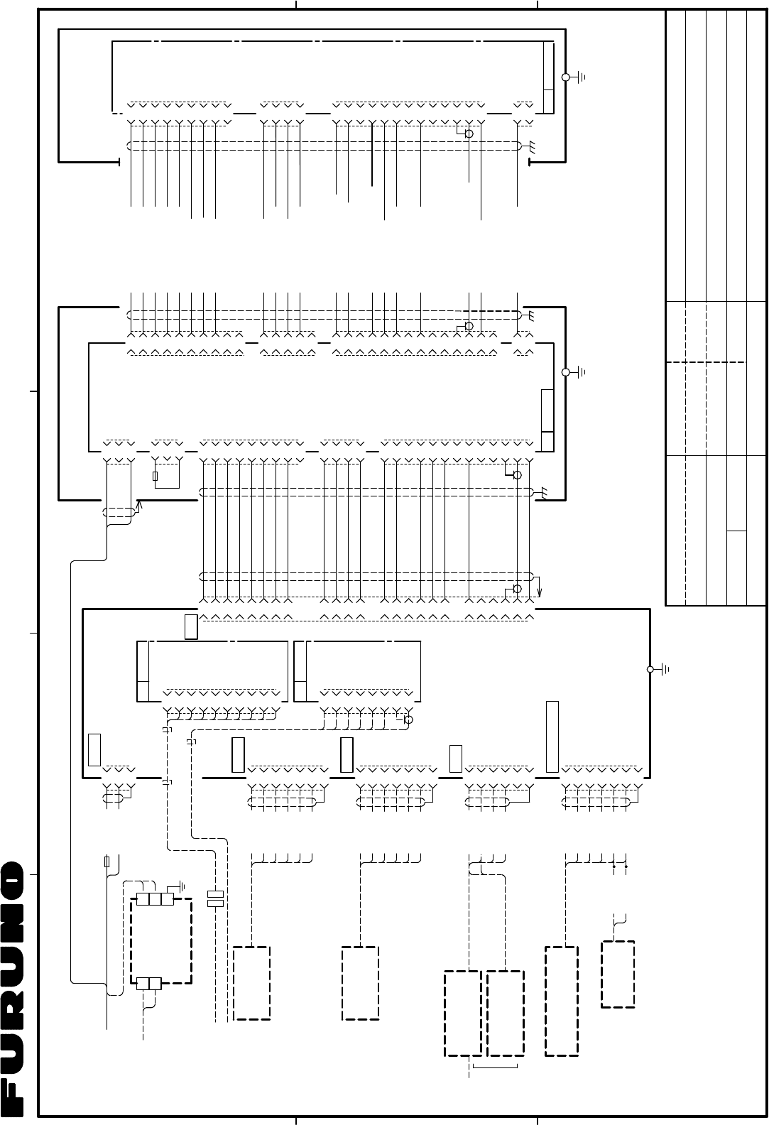
空中線電源部
POWER SUPPLY UNIT
PSU-008
RW-4747
J13(VH5P)
J14(NH14P)
J11(VH2P)
J12(VH10P)
14
13
12
11
10
9
8
7
6
5
4
3
2
1
5
4
3
2
1
10
9
8
7
6
5
4
3
2
1
2
1
*4
RW-9771,10/15/20/30m,φ14.5
(17C+2C2V,MAX.30m)
2C-2V COAX.
キ(太)
クロ(太)
アカ(太)
シロ(太)
チャ(太)
チャ
アオ
ミドリ
YEL[B]
BLK[B]
RED[B]
WHT[B]
BRN[B]
BRN
BLU
GRN
シロ
アオ(太)
クロ
ムラサキ(太)
WHT
BLU[B]
BLK
PPL[B]
シロ/チャ
ミドリ(太)
シロ/アカ(太)
アカ
モモ(太)
シロ/ダイ
WHT/BRN
GRN[B]
WHT/RED[B]
RED
PNK[B]
WHT/ORG
キ YEL
ダイ(太)ORG[B]
ドウジク
*4
J820(VH2P)
4
3
2
1
5
6
7
8
9
10
11
12
13
2
1
*5
*5
*5
1
2
3
4
9
8
7
6
5
4
3
2
1
RTB 03P9405B
MOTOR-
HD
MOTOR+
BP
TX_TRIG
-12V
+12V
-12V
GND
+12V
P/L B
P/L A
VIDEO_GND
MOTOR+
MOTOR+
MBS_L
MOTOR(-)OUT
VIDEO
GND
TUNE_CONT
TUNE_IND.
NC
TX-HV
NC
NC
NC
NC
J824(NH13P)
J823(VH4P)
J821(VH9P)
空中線部
ANTENNA UNIT
J2(VL3P)
1
2
3
15A:12V
7A:24V
10
11
20
14
15
2
8
7
17
15
9
1
18
22
19
3
4
23
24
21
16
6
13
12
*4
DJ-1 5m,φ11
MJ-B24LPF0011-050 J3(VH9P)
9
1
5
6
2
3
4
7
8
-12V
GND
+12V
+12V
-12V
TX-TRIG.
P/L-A
P/L-B
NC
J4(VH4P)
4
3
2
1BP
MOTOR+
HD.
MOTOR-
J5(NH13P)
TUNE-IND.
MOTOR-
NC
MOTOR+
MBS-L
MOTOR+
NC
GND
NC
NC
GND
VIDEO
TUNE-CONT
4
3
2
1
5
6
7
8
9
10
11
12
13
*4
03P9419
PWR
IV-2sq.
*1
NAME
TYPE
名称
DRAWN
CHECKED
APPROVED
SCALE
kg
MASS
REF.No.DWG.No.
H.MAKI
03-167-6005-3
T.YAMASAKI
相互結線図
INTERCONNECTION DIAGRAM
船舶用レーダー
MARINE RADAR
FR-8252
NOTE
*3: FITTED AT FACTORY.
*4: GROUND SHIELD EFFECTIVELY AT BOTH ENDS.
*2: OPTION.
*1: SHIPYARD SUPPLY.
*5: ATTACH EMI CORES.
注記
*5) EMIコアを取り付ける。
*1) 造船所手配。
*2) オプション。
*3) コネクタは工場にて取付済み。
*4) シールドは両端で完全にアースする。
RSB-0073/RTR-087A
25/Mar/2011
25/Mar/2011
C3541-C01- H
24/Jan/2011 Y.NISHIYAMA
S-2