Furuno USA 9ZWRTR087A Marine Radar User Manual inst man part 2
Furuno USA Inc Marine Radar inst man part 2
UserManual.wiki
>
Furuno USA
>
9ZWRTR087A User Manual
>
inst man part 2
Contents
1.
inst man part 1
2.
inst man part 2
inst man part 2
Navigation menu
Upload a User Manual
Namespaces
Wiki Guide
HTML
PDF
Info
Views
User Manual
Discussion / Help
Navigation
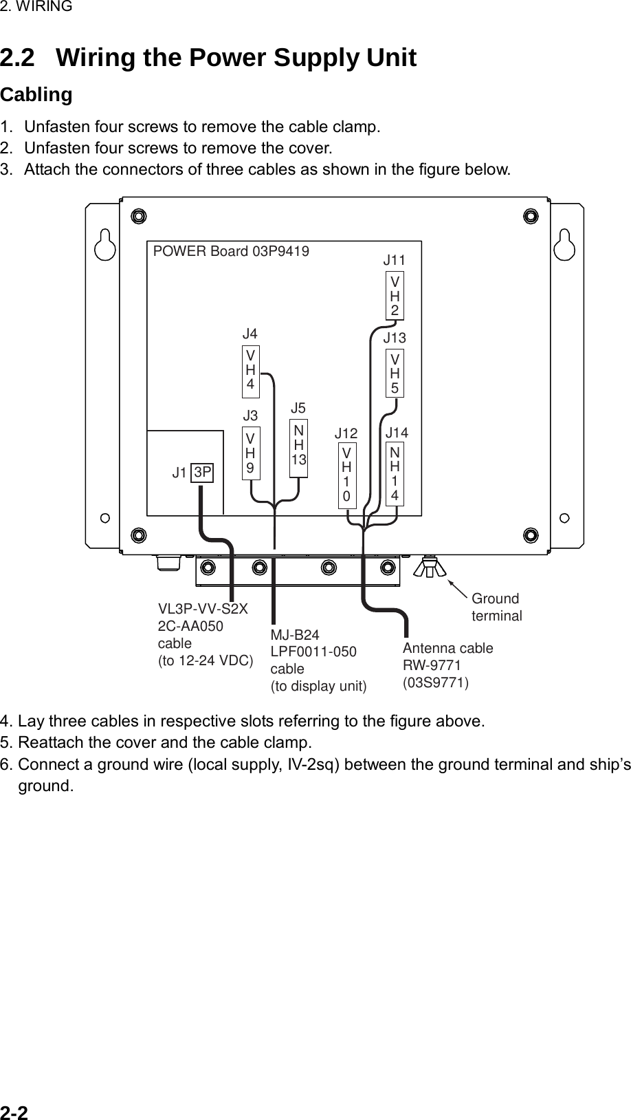
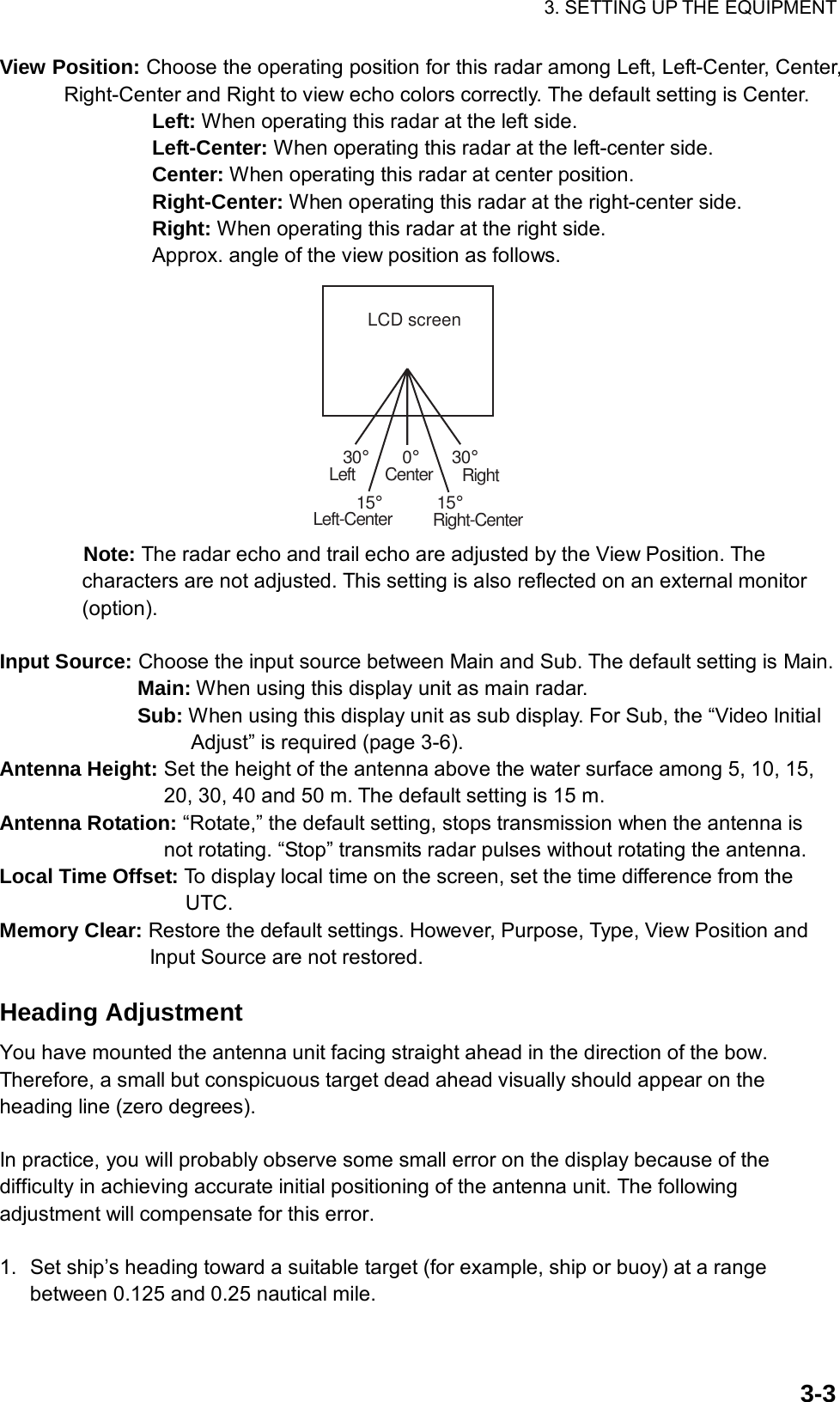
![3. SETTING UP THE EQUIPMENT 3-2 3.2 Opening the Installation Menu After you have installed the equipment, set it up as follows. 1. Press the MENU key. The main menu appears on the screen. 2. Rotate the trackball downward to choose Installation. The installation menu appears in gray to right side of the screen. 3. While pressing down the CANCEL/HL OFF key, press the MENU key five times to activate the Installation menu. [ENTER]: Enter [CANCEL/HL OFF]: Back[MENU]: ExitSystemGPSMarkCustom 1 Custom 2Custom 3 TargetARPAISTuningType View PositionInput Source Language Purpose Antenna HeightHeading Adjust : Center: Main: 5 m: 0 °: 8062: English: SeaTuning Initial Adjust Manual MBS AdjustAuto Installation Setup** Manual Timing Adjust Local Time Offset: 0: - 0.1 H: 0Menu InstallationInitialFactorySector Blank 1**Installation Total TX Time* : 000000.5 hTotal On Time* : 000000.6 h* : Displayed when scrolled.Memory Clear*** : Set the Sector Blank to "Off" in order to execute Auto Installation Setup in the Installation menu.GPS BuoyVideo Initial Adjust : 0Antenna Rotation : Rotate 4. Press the ENTER key. The highlighted cursor appears in the Installation menu. 5. Rotate the trackball downward or upward to choose an item in the Installation menu. 6. Press the ENTER key to show setting window. 7. Rotate the trackball downward or upward to choose an option. 8. Press the ENTER key to confirm setting. 9. Finally, press the MENU key to close the main menu. Basic Settings Language: Choose an appropriate language. Purpose: Choose the purpose of this radar among River, Sea and IEC. The default setting is Sea. River: To use this radar on a river. Sea: To use this radar on high seas. IEC: To use this radar as the type approved radar. Type: Choose type of this radar among 8062 (6 kW radar), 8122 (12 kW radar) and 8252 (25 kW radar) to agree with the specifications of the antenna unit. The default setting is 8062. Unsuitable setting may result in malfunction.](https://usermanual.wiki/Furuno-USA/9ZWRTR087A.inst-man-part-2/User-Guide-1456685-Page-5.png)
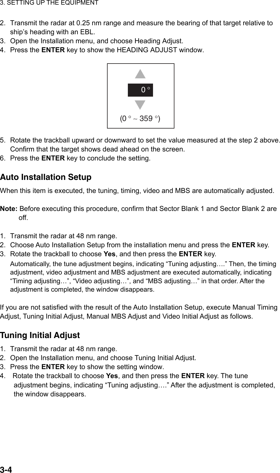

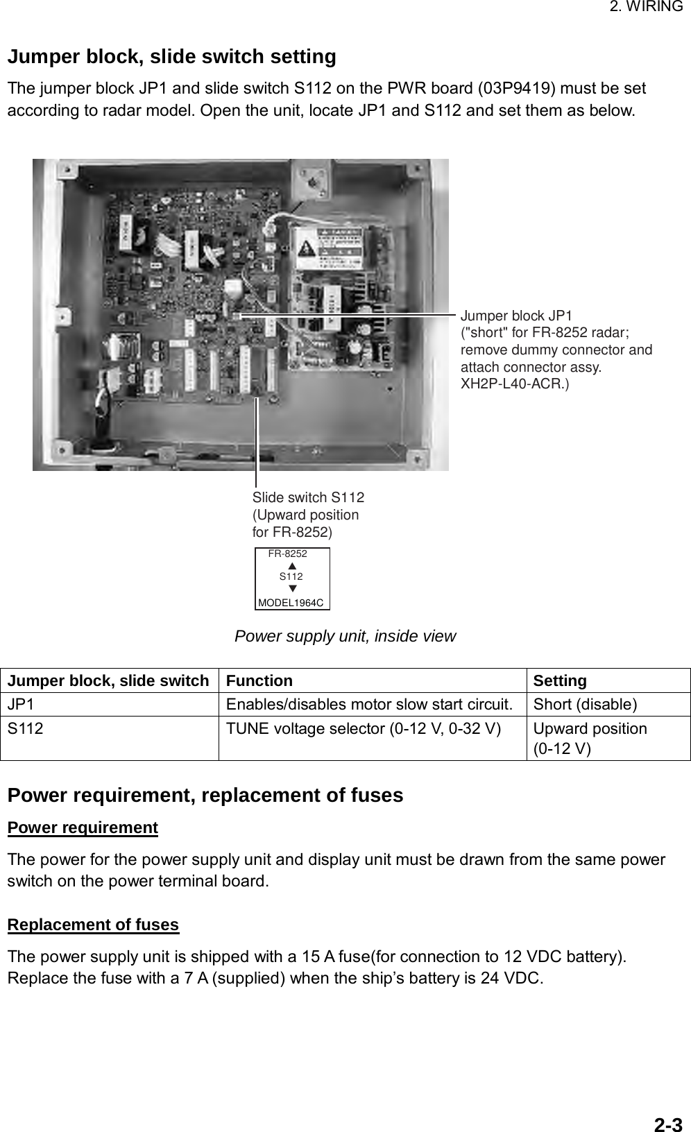
![12 43BACFURUNO ELECTRIC CO., LTD.*3123456NMEA1MJ-A7SPFSGRD1-CRD1-HTD1-BTD1-A7SHIELD+12VGRNYELWHTキシロミドリBLKクロアカ REDアオ BLU航法装置NAV EQUIPMENT(NMEA0183) 5m,φ7*2*3123456MJ-A7SPFSG7SHIELD+12VGRNYELWHTキシロミドリBLKクロアカ REDアオ BLU航法装置NAV EQUIPMENT(NMEA0183) 5m,φ7*2HDGGNDNCCLK-CCLK-HDATA-CDATA-HMJ-A6SPF*3123456RDP-150DISPLAY UNIT指示部123456MJ-A7SPF7SHIELD+12VGRNYELWHTキシロミドリBLKクロアカ REDアオ BLU*2 PC/EXT-BUZZERSDRDREMOTE-KEYNCEXT.BUZZERBLKクロアカ RED5m,φ7EXT. BUZZEROP03-136外部ブザー*21mリモートコントローラREMOTE CONTROLLERRCU-019 *2*3TD2-ATD2-BRD2-HRD2-C*5シロクロWHTBLK15A:12V10A:24V MJ-A3SPF321POWERGND(-)(+)*3MJ-A3SPF0018-050ZC5m,φ1012-24 VDC*5*5MJ-A7SPF0007-050CMJ-A7SPF0007-050CMJ-A7SPF0007-050CNMEA2(03S9801)VL3P-VV-S2X2C-AA050,5m,φ1010/20/30m,φ11.4MJ-B24LPF000819S1004,0.5m3(+)(-) 224V761IV-2sq.PR-240AC/DC POWERSUPPLY UNITAC/DC電源ユニット*2 *1キクロシロGRNYELBLKWHTミドリMJ-A6SPF0003-050C/100C*2A-D CONVERTERA-DコンバータAD-100HEADING SENSORPG-1000ヘディングセンサー*2*2選択SELECT5/10m,φ610m,φ6MJ-A6SPF0007-100C*287654321GNDGNDGNDTRU-HDGNDJ110(NH8P)VIDEOPR-TRIGDP-BPSPU87654321GND910RGB 03P9429GNDGNDGNDGNDV_SYNCH_SYNCBGRJ802 *2*203P9411ジャイロGYRODPYC-1.5*1220/230 VAC100/110/115/1φ,50/60HzDsub15PSVGA MONITORSVGAモニターREMOTE DISPLAY副指示器SVGA MONITOR CABLE*1*1IV-2sq.321J1(VL3P)(-)(+)空中線電源部POWER SUPPLY UNITPSU-008RW-4747J13(VH5P)J14(NH14P)J11(VH2P)J12(VH10P)1413121110987654321543211098765432121*4RW-9771,10/15/20/30m,φ14.5(17C+2C2V,MAX.30m)2C-2V COAX.キ(太)クロ(太)アカ(太)シロ(太)チャ(太)チャアオミドリYEL[B]BLK[B]RED[B]WHT[B]BRN[B]BRNBLUGRNシロアオ(太)クロムラサキ(太)WHTBLU[B]BLKPPL[B]シロ/チャミドリ(太)シロ/アカ(太)アカモモ(太)シロ/ダイWHT/BRNGRN[B]WHT/RED[B]REDPNK[B]WHT/ORGキ YELダイ(太)ORG[B]ドウジク*4J820(VH2P)4321567891011121321*5*5*51234987654321RTB 03P9405BMOTOR-HDMOTOR+BPTX_TRIG-12V+12V-12VGND+12VP/L BP/L AVIDEO_GNDMOTOR+MOTOR+MBS_LMOTOR(-)OUTVIDEOGNDTUNE_CONTTUNE_IND.NCTX-HVNCNCNCNCJ824(NH13P)J823(VH4P)J821(VH9P)空中線部ANTENNA UNITJ2(VL3P)12315A:12V7A:24V1011201415287171591182219342324211661312*4DJ-1 5m,φ11MJ-B24LPF0011-050 J3(VH9P)915623478-12VGND+12V+12V-12VTX-TRIG.P/L-AP/L-BNCJ4(VH4P)4321BPMOTOR+HD.MOTOR-J5(NH13P)TUNE-IND.MOTOR-NCMOTOR+MBS-LMOTOR+NCGNDNCNCGNDVIDEOTUNE-CONT43215678910111213*403P9419PWRIV-2sq.*1NAMETYPE名称DRAWNCHECKEDAPPROVEDSCALEkgMASSREF.No.DWG.No.H.MAKI03-167-6005-3T.YAMASAKI相互結線図INTERCONNECTION DIAGRAM船舶用レーダーMARINE RADARFR-8252NOTE*3: FITTED AT FACTORY.*4: GROUND SHIELD EFFECTIVELY AT BOTH ENDS.*2: OPTION.*1: SHIPYARD SUPPLY.*5: ATTACH EMI CORES.注記*5) EMIコアを取り付ける。*1) 造船所手配。*2) オプション。*3) コネクタは工場にて取付済み。*4) シールドは両端で完全にアースする。RSB-0073/RTR-087A25/Mar/201125/Mar/2011C3541-C01- H24/Jan/2011 Y.NISHIYAMAS-2](https://usermanual.wiki/Furuno-USA/9ZWRTR087A.inst-man-part-2/User-Guide-1456685-Page-31.png)