Furuno USA 9ZWRTR088B Transceiver for Radar model FR-8045 User Manual
Furuno USA Inc Transceiver for Radar model FR-8045
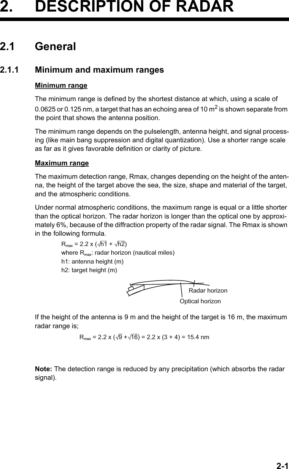
UserManual.wiki
>
Furuno USA
>
9ZWRTR088B User Manual
>
User Manual II Part 3
Contents
1.
Internal Photos
2.
User Manual I Part 1
3.
User Manual I Part 2
4.
User Manual II Part 1
5.
User Manual II Part 2
6.
User Manual II Part 3
User Manual II Part 3
Navigation menu
Upload a User Manual
Namespaces
Wiki Guide
HTML
PDF
Info
Views
User Manual
Discussion / Help
Navigation
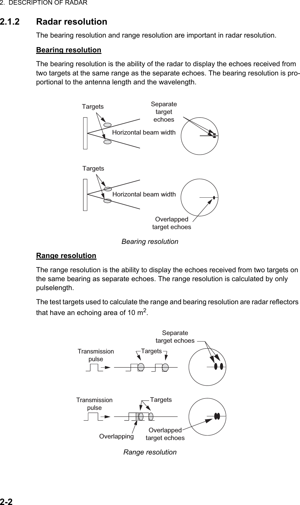
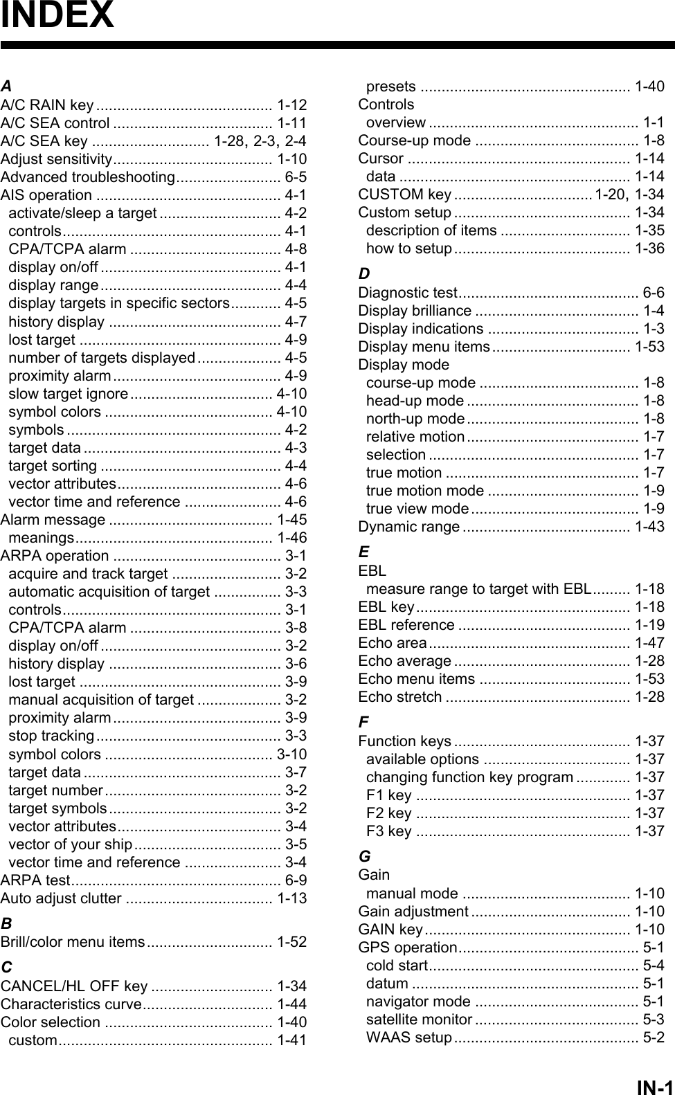
![2. DESCRIPTION OF RADAR2-62.3.2 General remarks on receiving SARTSART range errorsWhen the SART is at a range greater than approximately 1 nm, the first dot is dis-played at 0.64 nm past the true position of the SART. When the range closes so that the fast-sweep responses are also seen, the first range echoes are displayed at 150 m past the true position.Range scaleWhen you find the SART position, do as follows:1. Use the RANGE key to set the range scale to 6 nm or 12 nm.2. Turn off [A/C Auto].3. Turn off [Int Rejector].SART displayTo display only the SART echo clearly on the radar screen, reduce the tuning on man-ual mode. The normal radar echoes get weak, but the SART echoes remain. Your ship comes near the SART, the arc for the SART display becomes larger. Most of the radar screen becomes fuzzy. Adjust the A/C SEA and GAIN controls to display the neces-sary screen.2.4 RACONThe RACON is a RAdar beaCON which sends radar-receivable signals in the radar frequency spectrum (X- or S-band). There are several signal formats; in general, the RACON signal appears on the radar screen as an echo in the shape of a rectangle originating at a point just past the position of the radar beacon. It has a Morse coded pattern. Note that the position on the radar display is not accurate.Echo descriptionYour ship positionRACON signalRACON stationEchoes on the radar screen](https://usermanual.wiki/Furuno-USA/9ZWRTR088B.User-Manual-II-Part-3/User-Guide-2264467-Page-6.png)
![3-13. ARPA OPERATIONThe Automatic Radar Plotter ARP-11 (option) manually or automatically acquires and tracks ten targets. When a target is acquired automatically or manually, a target is au-tomatically tracked within 0.1 to 16 nm.3.1 Precautions for Use3.2 Controls for Use with ARPAENTER: Acquire the cursor-selected target. Display data for tracked target (in the data box at the bottom of the screen).CANCEL/HL OFF: Remove data of cursor-selected tracked target from the data box. Stop tracking the cursor-selected target (when its data is not displayed in the data box).MENU: Access the [Target] and [ARPA] menus for ARPA operations.CursorPad: Select a target to acquire (or cancel the tracking). Select a target to show (or remove) target data.Do not depend on one navigation devicefor the navigation of the ship. Thenavigator must check all aids availableto confirm position. Electronic aids arenot a replacement for basic navigationprinciples and common sense.· The ARPA automatically tracks an automatically or manually acquired radar target and calculates its course and speed, indicating them by a vector. Since the data from the auto plotter depend on the selected radar targets, the radar must be optimally tuned for use with the auto plotter, to ensure required targets will not be lost or unnecessary targets like sea returns and noise will not be acquired and tracked.· A target is not always a landmass, reef, ship, but can be returns from the sea surface and clutter. As the level of clutter changes with the environment, the operator must correctly adjust the A/C SEA, A/C RAIN and GAIN controls so that the target echoes do not disappear from the radar screen.The plotting accuracy and response ofthis ARPA meets IMO standards.The tracking accuracy is affected by thefollowing:· The tracking accuracy is affected by course change. One to two minutes is required to restore vectors to full accuracy after a sudden course change. (The actual amount depends on gyrocompass specifications.)· The amount of tracking delay is inversely proportional to the relative speed of the target. Delay is on the order of 15-30 seconds for high relative speed; 30-60 seconds for low relative speed.The display accuracy is affected by thefollowing:· Echo intensity· Pulse width of radar transmission· Radar bearing error· Gyrocompass error· Course change (your ship or target)CAUTIONCAUTIONCAUTIONCAUTION](https://usermanual.wiki/Furuno-USA/9ZWRTR088B.User-Manual-II-Part-3/User-Guide-2264467-Page-7.png)
![3. ARPA OPERATION3-23.3 ARPA Display On/OffYou can turn the ARPA display on or off. The system continuously tracks ARPA tar-gets regardless of this setting.1. Press the MENU key to open the menu.2. Use S or T to select [ARPA] and press the ENTER key.3. Use S or T to select [Display] and press the ENTER key.ARPA Display options4. Use S or T to select [Off] or [On] then press the ENTER key.5. Press the MENU key to close the menu.3.4 How to Acquire and Track the TargetsTen targets are acquired and tracked manually or automatically.3.4.1 Manual acquisitionYou can acquire a maximum of ten ARPA targets. When the automatic acquisition ([Auto Acquisition] on the [ARPA] menu) is set to on, you can manually acquire a max-imum of five targets.1. Use the CursorPad to put the cursor on the target to acquire.2. Press the ENTER key.The ARPA target symbol changes over time as shown below. A vector which indicates the motion direction of the target appears approximately one minute after the acquisi-tion.ARPA target symbolTarget number[River] and [Sea] (Non-IEC system): An acquired target gets the youngest unused number. When a target is lost and disappears from the number list, the next acquired target takes the number of that lost target (ie: In a five-target list, if the target 2 is lost, the next acquired target takes the number of target 2).[IEC] and [Russian-River] (IEC system): An acquired target gets the youngest un-used number. When a target is lost and disappears from the number list, the next ac-quired target takes the next sequential number until reaching a maximum 10. If the target number reaches a maximum 10, the next acquired target takes the number of a previously lost target.OffOnAt acquisition 1 min. afteracquisition3 min. afteracquisition01 Target numberVector0101](https://usermanual.wiki/Furuno-USA/9ZWRTR088B.User-Manual-II-Part-3/User-Guide-2264467-Page-8.png)
![3. ARPA OPERATION3-33.4.2 Automatic acquisitionWhen you set an automatic-acquisition area, the ARPA can acquire a maximum of five targets automatically. The automatic acquisition area is 2.0 to 2.5 nm in range and ±45° on either side of the heading line in bearing. When you change the automatic acquisition to the manual ac-quisition, targets tracked in automatic acquisition are continuously tracked.Automatic acquisition area1. Press the MENU key to open the menu.2. Use S or T to select [ARPA] and press the ENTER key.3. Use S or T to select [Auto Acquisition] and press the ENTER key.Auto Acquisition options4. Use S or T to select [On] and press the ENTER key.5. Press the MENU key to close the menu.3.5 How to Stop the Tracking of ARPA TargetWhen ten targets have been acquired, there is no more acquisition, unless targets are cancelled. If you acquire additional targets, you must cancel one or more separate tar-gets, or all targets. Use one of the following procedures.3.5.1 How to stop the tracking of selected targets1. Use the Cursorpad to put the cursor on the target to cancel the tracking.2. Press the CANCEL/HL OFF key to cancel the tracking and erase the ARPA sym-bol. The unit beeps twice and the symbol is erased from the screen.3.5.2 How to stop the tracking of all targets1. Press the MENU key to open the menu.2. Use the CursorPad to put the cursor on the target to cancel the tracking.3. Use S or T to select [ARPA] and press the ENTER key.Automatic acquisition area45° port 45° starboard2.0 - 2.5 nm Heading lineOffOn](https://usermanual.wiki/Furuno-USA/9ZWRTR088B.User-Manual-II-Part-3/User-Guide-2264467-Page-9.png)
![3. ARPA OPERATION3-44. Use S or T to select [All Cancel] and press the ENTER key.5. Use S to select [Yes] and press the ENTER key. All symbols are erased from the screen and the long beep sounds.6. Press the MENU key to close the menu.3.6 Vector Attributes3.6.1 What is a vector?A vector is a line extending from a tracked target. A vector shows speed and course of the target. The top of a vector shows estimated position of the target after the se-lected vector time elapses. If you increase the vector length (time), you can evaluate the risk of collision with any target.When vector time is 15 minutes3.6.2 Vector time and vector reference1. Press the MENU key to open the menu.2. Use S or T to select [Target] and press the ENTER key.Target menuAre your sure ?YesNoVectorCurrent position of the targetVector timePredicted position of the target in 15 minutes laterCustom 1Custom 2Target TrailCustom 3AlarmTargetTuningARPAOthersAISGPSMenu TargetVector ReferenceHistory DotsHistory IntervalProximity: True: 5: 1min: OffTCPA : 1minCPA: OffVector Time : 6min[ENTER]: Enter[MENU]: Exit[CANCEL/HL OFF]: BackAdjusting a vector time to be displayed](https://usermanual.wiki/Furuno-USA/9ZWRTR088B.User-Manual-II-Part-3/User-Guide-2264467-Page-10.png)
![3. ARPA OPERATION3-53. UseS or T to select [Vector Time] and press the ENTER key.Vector Time setting window4. Use S or T to select time and press the ENTER key.5. Use S or T to select [Vector Reference] and press the ENTER key.Vector Reference options6. Use S or T to select [Relative] or [True] then press the ENTER key. This function is not activate for [IEC] or [Russian-River] purpose. The mode is set to [True].[Relative]: Other ships’ vectors are displayed relative to your ship. This mode helps find the targets on a collision course. If a ship is on a collision course with your ship, the vector of a ship points toward your ship position.[True]: Your ship’s and other ships’ vectors are displayed at their true motions. This mode helps see the differences between moving and stationary targets.7. Press the MENU key to close the menu.Note: The functions of the [Target] menu are shared by ARPA and AIS.3.6.3 Vector of your shipThe vector of your ship is shown as an arrow from your ship position. The vector of your ship is shown on the following conditions:• Connect ARP-11 (option)• Select [True] on the menu item [Vector Reference] on the [Target] menu• Independent of on/off on the menu item [Display] on the [ARPA] menuNote: The vector of your ship is shown in the same color as the ARPA symbol color (see section 3.12).Example of vector display6min( 1min~30min)RelativeTrue+Vector ofyour ship01Data box02Cursor0304](https://usermanual.wiki/Furuno-USA/9ZWRTR088B.User-Manual-II-Part-3/User-Guide-2264467-Page-11.png)
![3. ARPA OPERATION3-63.7 History Display (target past position)This radar can display time-spaced dots (maximum ten dots) that mark the past posi-tions of any tracked ARPA target. You can evaluate actions of a target by the spaces in between the dots. Below are examples of dot spacing and target movement.Target movement and history displayYou can select the number of history dots to display and the time interval to display the history dots.1. Press the MENU key to open the menu.2. Use S or T to select [Target] and press the ENTER key.3. Use S or T to select [History Dots] and press the ENTER key.History Dots options4. Use S or T to select number of history dots to display (5 or 10) or select [Off] to turn off the history display.5. Press the ENTER key.6. Use S or T to select [History Interval] and press the ENTER key.History Interval options7. Use S or T to select the time interval and press the ENTER key.8. Press the MENU key to close the menu.(a) Ship turning (b) Ship runningstraight (c) Ship reducedspeed(d) Ship increasedspeedOff10515s30s2min3min6min12min1min](https://usermanual.wiki/Furuno-USA/9ZWRTR088B.User-Manual-II-Part-3/User-Guide-2264467-Page-12.png)
![3. ARPA OPERATION3-73.8 ARPA Target DataYou can show the data for a tracked ARPA target in the data box at the bottom of the screen. To display ARPA target data, the menu item [Display] on the [ARPA] menu must be set for [On] and the menu item [Data Box] on the [Display] menu must be set for [Target] or [All].1. Use the CursorPad to put the cursor on an ARPA target.2. Press the ENTER key to show the data of the target.ARPA target dataThe symbol for the selected ARPA target is enlarged double to identify it from other symbols.To remove the data of a target from a data box, put the cursor on its target symbol and press the CANCEL/HL OFF key.Vector referenceVector timeTarget no.Bearing, range, course,speed,CPA, TCPA+ARPA targetselected fordata display(B)01Data boxCursorTRUE 06:00<ARPA> No. 02ABRG 78.4ºT RNG 2.032NMSOG 0.49KNCRS 73.0ºTRUE 06:00<ARPA> No. 01BBRG 29.3ºT RNG 0.659NMSOG 0.10KNCRS 12.3º(A)02](https://usermanual.wiki/Furuno-USA/9ZWRTR088B.User-Manual-II-Part-3/User-Guide-2264467-Page-13.png)
![3. ARPA OPERATION3-83.9 CPA/TCPA AlarmSet [CPA] (Closest Point of Approach) alarm range and [TCPA] (predicted Time to CPA) alarm time to alert you to the targets that can be on a collision course. When [CPA] and [TCPA] of any ARPA target become less than the preset [CPA] and [TCPA] alarm settings, the audio alarm sounds. The alarm message "COLLISION" appears. The target symbol changes to a dangerous target symbol (triangle) and its vector flashes. You can stop the audio alarm with any key. The flashing of the triangle stops when the tracked CPA and TCPA of an ARPA target is not in the [CPA] and [TCPA] alarm setting. The ARPA continuously monitors [CPA] and [TCPA] of all tracked ARPA targets.Dangerous target symbolThis feature helps identify the targets that can be on a collision course. Correctly ad-just GAIN, A/C SEA, A/C RAIN and other radar controls.1. Press the MENU key to open the menu.2. Use S or T to select [Target] and press the ENTER key.3. Use S or T to select [CPA] and press the ENTER key.4. Use S or T to select [CPA] distance and press the ENTER key. 5. Use S or T to select [TCPA] and press the ENTER key.6. Use S or T to select TCPA and press the ENTER key.7. Press the MENU key to close the menu.CAUTIONCAUTIONDo not depend on the CPA/TCPA alarmas the only method to detect the risk ofcollision. The navigator is not releasedof the responsibility to keep visual cautionfor collision situations, whether or not theradar or other plotting aid is in use.Off0.5NM1NM2NM3NM5NM6NM 6min30s2min3min4min5min1min12minCPA distance settings TCPA settings](https://usermanual.wiki/Furuno-USA/9ZWRTR088B.User-Manual-II-Part-3/User-Guide-2264467-Page-14.png)
![3. ARPA OPERATION3-93.10 Proximity AlarmThe proximity alarm alerts you when an ARPA target is within the range you set. The audio alarm sounds and the alarm message "PROXIMITY" appears. The target sym-bol changes to a dangerous target symbol (triangle, see section 3.9) and flashes with its vector. Press any key to stop the audio alarm. The flashing continues until the tar-get is not within the range set, the alarm range is changed to exclude the target, or the proximity alarm is deactivated.1. Press the MENU key to open the menu.2. Use S or T to select [Target] and press the ENTER key.3. Use S or T to select [Proximity] and press the ENTER key.Proximity settings4. Use S or T to select the range and press the ENTER key.5. Press the MENU key to close the menu.3.11 Lost TargetWhen the system detects a lost target, the audio alarm sounds and the alarm message "LOST" appears. The target symbol becomes a flashing square like the illustration to the right. When the system detects the target again, the target symbol becomes a normal symbol.To erase a lost target symbol, put the cursor on the symbol and press the CANCEL/ HL OFF key. If you leave a lost target symbol flashing, the symbol disappears after one minute.You can remove all lost ARPA targets from the screen as follows:1. Press the MENU key to open the menu.2. Use S or T to select [ARPA] and press the ENTER key.3. Use S or T to select [ACK Lost Targets] and press the ENTER key.ACK Lost Targets options4. Use S to select [Yes] and press the ENTER key. All lost targets symbols are erased from the screen and the long beep sounds.5. Press the MENU key to close the menu.Lost target symbolAre you sure?YesNo](https://usermanual.wiki/Furuno-USA/9ZWRTR088B.User-Manual-II-Part-3/User-Guide-2264467-Page-15.png)
![3. ARPA OPERATION3-103.12 Symbol ColorYou can select the ARPA symbol color from Green, Red, Blue, White or Black.1. Press the MENU key to open the menu.2. Use S or T to select [ARPA] and press the ENTER key.3. Use S or T to select [Color] and press the ENTER key.Color options4. Use S or T to select the color and press the ENTER key.5. Press the MENU key to close the menu.Note: Symbols can not be shown in the same color as the background color.RedBlueWhiteBlackGreen](https://usermanual.wiki/Furuno-USA/9ZWRTR088B.User-Manual-II-Part-3/User-Guide-2264467-Page-16.png)
![4-14. AIS OPERATIONConnected to the FURUNO AIS Transponders FA-150, FA-100, FA-50 or the AIS Re-ceiver FA-30, the FR-8045/FR-8065/FR-8125/FR-8255 series can show the name, position and other navigation data of the nearest 100 AIS transponder-equipped ships.This radar accepts heading and position data fixed by WGS-84 geodetic datum. Set the datum to WGS-84 on the GPS navigator connected to this radar. If this radar is connected with the FURUNO GPS Navigator GP-320B, see section 5.2 for the proce-dure.4.1 Controls for Use with AISENTER: Activate the cursor-selected target. Display data for the selected active target (in the data box at the bottom of the screen).CANCEL/HL OFF: Remove data of cursor-selected AIS target from the data box. Sleep the cursor-selected target (when its data is not displayed in the data box).MENU: Access the [Target] and [AIS] menus for AIS operations.CursorPad: Select a target to activate (or sleep). Select a target to show (or remove) target data.4.2 AIS Display On/OffYou can turn the AIS display on or off. The system continues processing AIS targets regardless of on/off for AIS display when the AIS transponder is turned on.1. Press the MENU key to open the menu.2. Use S or T to select [AIS] and press the ENTER key.AIS menuCustom 1Custom 2Custom 3AlarmTarget TrailsTuningOthersTargetARPAAISGPSColorNumber of TargetsSort BySector End: Green: 30: Range: 24.0NMSector Start : 340°RangeIgnore Slow TargetsACK Lost Targets: 20°: 5.0knDisplay : On[ENTER]: Enter[MENU]: Exit[CANCEL/HL OFF]: BackTurning on/off AIS display](https://usermanual.wiki/Furuno-USA/9ZWRTR088B.User-Manual-II-Part-3/User-Guide-2264467-Page-17.png)
![4. AIS OPERATION4-23. Use S or T to select [Display] and press the ENTER key.AIS-Display options4. Use S or T to select [Off] or [On] then press the ENTER key.5. Press the MENU key to close the menu.4.3 AIS SymbolsWhen the AIS is turned on, AIS targets are displayed with AIS symbol as shown be-low.AIS symbolsNote: When the heading is changed on the head up mode, the AIS symbols are erased, after the screen is changed, for a short time.4.4 Activating, Sleeping TargetsWhen you change a sleeping target to an activated target, a vector shows the course and speed of that target. You can easily judge the target movement by the vector.Activated targetOffOnSleepingtarget ActivatedtargetDangerous targetLost target Target selectedfor data displayHeading lineSOG (Speed Over Ground) andCOG (Course over Ground) vector(If there is no heading data,the line points in direction of COG.)ROT(Rate of Turn)](https://usermanual.wiki/Furuno-USA/9ZWRTR088B.User-Manual-II-Part-3/User-Guide-2264467-Page-18.png)
![4. AIS OPERATION4-3When there are many activated targets on the screen, you can not easily identify the activated targets from the radar images or ARPA targets. You can sleep an activated target for easy view of radar images.Sleeping targetTo activate a target: Put the cursor on the target and press the ENTER key.To sleep a target: Put the cursor on the target and press the CANCEL HL/OFF key.4.5 AIS Target DataYou can show the AIS target data in the data box at the bottom of the screen. To dis-play AIS target data, the menu item [Display] on the [AIS] menu must be set for [On] and the menu item [Data Box] on the [Display] menu must be set for [Target] or [All].1. Use the CursorPad to put the cursor on an activated target.2. Press the ENTER key to show the data of the target.To remove the target data from a data box, put the cursor on its target symbol and press the CANCEL/HL OFF key.AIS targetselected fordata displayMMSI of vessel Name ofvessel PEGASUSCursorData boxTRUE 05:00 <AIS> MMSI: 123456789 NAME: PEGASUSBRG 53.7°T RNG 2.987NM COG 350.4° SOG 23.45KNCPA 1.65NM TCPA 06:14 LEN 100M BEAM 45M Vector referenceVector timeBearing, range, course, speed CPA, TCPA, length, beam of vessel+Name of vessel(or MMSI)](https://usermanual.wiki/Furuno-USA/9ZWRTR088B.User-Manual-II-Part-3/User-Guide-2264467-Page-19.png)
![4. AIS OPERATION4-44.6 How to Sort TargetsYou can sort the AIS targets received from the AIS transponder by range from your ship, by sector, by CPA or TCPA.1. Press the MENU key to open the menu.2. Use S or T to select [AIS] and press the ENTER key.3. Use S or T to select [Sort By] and press the ENTER key.Sort By options4. Use S or T to select sorting method and press the ENTER key.[Range]: Sort targets within the display range set (see section 4.7), from nearest to furthest.[Sector]: Sort targets within the display sector set (see section 4.8) and within 24 nm, from nearest to furthest.[CPA]: Sort targets within 24 nm by CPA, from closest to furthest.[TCPA]: Sort targets within 24 nm by TCPA, from earliest time to latest time.5. Press the MENU key to close the menu.4.7 Display RangeYou can set the AIS system to show only those AIS targets within the range you set. The setting range is 0.1NM - 48.0NM for FR-8045, 0.1NM - 72.0NM for FR-8125/FR-8065 and 0.1NM - 96.0NM for FR-8255. Actual range depends on the AIS Transpon-der. If the target sorting method is selected to [Range], the target data within the range set here are transmitted to this radar.1. Press the MENU key to open the menu.2. Use S or T to select [AIS] and press the ENTER key.3. Use S or T to select [Range] and press the ENTER key.AIS-Range setting window (for FR-8255)4. Use S or T to set the display range and press the ENTER key.5. Press the MENU key to close the menu.Note: The unit of measurement for range is NM.RangeSectorCPATCPA](https://usermanual.wiki/Furuno-USA/9ZWRTR088B.User-Manual-II-Part-3/User-Guide-2264467-Page-20.png)
![4. AIS OPERATION4-54.8 How to Display the Targets within a Specific Sec-torYou can display AIS targets only within a specified sector. If the target sorting method is selected to [Sector], the target data within the sector set here are transmitted to this radar.1. Press the MENU key to open the menu.2. Use S or T to select [AIS] and press the ENTER key.3. Use S or T to select [Sector Start] and press the ENTER key.Sector Start setting window4. Use S or T to set the start point for the sector and press the ENTER key.5. Use S or T to select [Sector End] and press the ENTER key.Sector End setting window6. Use S or T to set the end point for the sector and press the ENTER key.7. Press the MENU key to close the menu.4.9 Number of Targets to DisplayYou can select the maximum number of AIS targets to display. The setting value is 10 to 100. When the screen becomes full of AIS targets, you can limit the number of AIS targets to show. Targets are selected and displayed according to sort method. (See section 4.6.)1. Press the MENU key to open the menu.2. Use S or T to select [AIS] and press the ENTER key.3. Use S or T to select [Number of Targets] and press the ENTER key.Number of Targets setting window4. Use S or T to select the number of targets to display and press the ENTER key.5. Press the MENU key to close the menu.](https://usermanual.wiki/Furuno-USA/9ZWRTR088B.User-Manual-II-Part-3/User-Guide-2264467-Page-21.png)
![4. AIS OPERATION4-64.10 Vector Attributes4.10.1 What is a vector?A vector is a line extending from a tracked target. A vector shows speed and course of the target. The top of a vector shows estimated position of the target after the se-lected vector time elapses. If you increase the vector length (time), you can evaluate the risk of collision with any target.4.10.2 Vector time and vector reference1. Press the MENU key to open the menu.2. Use S or T to select [Target] and press the ENTER key.3. Use S or T to select [Vector Time] and press the ENTER key.Vector Time setting window4. Use S or T to select time and press the ENTER key.5. Use S or T to select [Vector Reference] and press the ENTER key.Vector Reference options6. Use S or T to select [Relative] or [True] then press the ENTER key. This function is not activate for [IEC] or [Russian-River] purpose. The mode is set to [True].[Relative]: Other ships’ vectors are displayed relative to your ship. This mode helps find targets on a collision course. If a ship is on a collision course with your ship, the vector of a ship points toward your ship position. [True]: Your ship’s and other ships’ vectors are displayed at their true motions. This mode helps see the differences between moving and stationary targets.7. Press the MENU key to close the menu.6min( 1min~30min)TrueRelative](https://usermanual.wiki/Furuno-USA/9ZWRTR088B.User-Manual-II-Part-3/User-Guide-2264467-Page-22.png)
![4. AIS OPERATION4-74.11 History Display (target past position)This radar can display time-spaced dots (maximum ten dots) that marks the past po-sitions of any tracked AIS target. You can evaluate actions of a target by the spaces between the dots. Below are examples of dot spacing and target movement.You can select the number of history dots to display and the time interval to display the history dots.1. Press the MENU key to open the menu.2. Use S or T to select [Target] and press the ENTER key.3. Use S or T to select [History Dots] and press the ENTER key.History Dots options4. Use S or T to select number of history dots to display (5 or 10) or select [Off] to turn off the history display.5. Press the ENTER key.6. Use S or T to select [History Interval] and press the ENTER key.History Interval options7. Use S or T to select time interval and press the ENTER key.8. Press the MENU key to close the menu.(a) Ship turning (b) Ship running straight(c) Ship reduced speed(d) Ship increased speedOff10515s30s2min3min6min12min1min](https://usermanual.wiki/Furuno-USA/9ZWRTR088B.User-Manual-II-Part-3/User-Guide-2264467-Page-23.png)
![4. AIS OPERATION4-84.12 CPA/TCPA AlarmSet CPA (Closest Point of Approach) alarm range and TCPA (predicted Time to CPA) alarm time to alert you to targets that can be on a collision course. When CPA and TCPA of any AIS target (including a sleeping target) become less than the preset CPA and TCPA alarm settings, the audio alarm sounds. The alarm message "COLLISION" appears. The target symbol changes to a dangerous target symbol (red) and its vector flashes. You can stop the audio alarm and flashing with any key. The dangerous target symbol is displayed until the AIS target is not in the CPA and TCPA alarm setting. The AIS continuously monitors CPA and TCPA of all AIS targets.This feature helps identify the targets that can be on a collision course.1. Press the MENU key to open the menu.2. Use S or T to select [Target] and press the ENTER key.3. Use S or T to select [CPA] and press the ENTER key.CPA options4. Use S or T to select [CPA] distance and press the ENTER key.5. Use S or T to select [TCPA] and press the ENTER key.TCPA options6. Use S or T to select [TCPA] and press the ENTER key.7. Press the MENU key to close the menu.0.5NM1NM2NM3NM6NM5NMOff12min6min5min4min3min2min1min30s](https://usermanual.wiki/Furuno-USA/9ZWRTR088B.User-Manual-II-Part-3/User-Guide-2264467-Page-24.png)
![4. AIS OPERATION4-94.13 Proximity AlarmThe proximity alarm alerts you when an AIS target is within the range you set. The au-dio alarm sounds and the alarm message "PROXIMITY" appears. The target symbol changes to a dangerous target symbol (red) and its vector flashes. Press any key to stop the audio alarm and flashing. The dangerous target symbol is displayed until the target is not within the range set, or the alarm range is changed to exclude the target, or the proximity alarm is deactivated.1. Press the MENU key to open the menu.2. Use S or T to select [Target] and press the ENTER key.3. Use S or T to select [Proximity] and press the ENTER key.Proximity options4. Use S or T to select the range and press the ENTER key.5. Press the MENU key to close the menu.4.14 Lost TargetWhen AIS data is not received from a target at fixed interval (3-5* report intervals), the target symbol changes to the lost target symbol (flashing). No audio or visual alarm is given for a lost target.Lost target symbol* The interval at which AIS data is sent depends on speed of the AIS transponder. For detailed information, refer to the Operator's Manual for the AIS transponder.You can remove all lost AIS targets from the display as follows:1. Press the MENU key to open the menu.2. Use S or T to select [AIS] and press the ENTER key.3. Use S or T to select [ACK Lost Targets] and press the ENTER key.ACK Lost Targets options24NM12NM6NM5NM3NM2NM1NM0.5NMOffAre you sure ?YesNo](https://usermanual.wiki/Furuno-USA/9ZWRTR088B.User-Manual-II-Part-3/User-Guide-2264467-Page-25.png)
![4. AIS OPERATION4-104. Use S to select [Yes] and press the ENTER key. All lost targets symbols are erased from the screen and the long beep sounds.5. Press the MENU key to close the menu.4.15 Symbol ColorYou can select the AIS symbol color from Green, Red (not available in the [IEC] or [Russian-River] purpose), Blue, White or Black.1. Press the MENU key to open the menu.2. Use S or T to select [AIS] and press the ENTER key.3. Use S or T to select [Color] and press the ENTER key.Color options4. Use S or T to select the color and press the ENTER key.5. Press the MENU key to close the menu.Note: Symbols can not be shown in the same color as the background color.4.16 How to Ignore Slow TargetsYou can prevent activation of the CPA/TCPA alarm against AIS targets that move at a speed lower than set here. The AIS symbols are not affected by this setting.1. Press the MENU key to open the menu.2. Use S or T to select [AIS] and press the ENTER key.3. Use S or T to select [Ignore Slow Targets] and press the ENTER key.Ignore Slow Targets settings window4. Use S or T to select speed (0.0 - 9.9 kn) and press the ENTER key.5. Press the MENU key to close the menu.GreenRedBlueWhiteBlack](https://usermanual.wiki/Furuno-USA/9ZWRTR088B.User-Manual-II-Part-3/User-Guide-2264467-Page-26.png)
![5-15. GPS OPERATIONIf the FURUNO GPS Navigator GP-320B is connected to this radar, you can set GP- 320B from this radar.5.1 Navigator Mode1. Press the MENU key to open the menu.2. Use S or T to select [GPS] and press the ENTER key.3. Use S or T to select [Mode] and press the ENTER key.Mode options4. Use S or T to select [GPS] or [WAAS] then press the ENTER key.5. Press the MENU key to close the menu.5.2 DatumSelect the type of datum which matches the paper charts you use for navigation. Se-lect [WGS-84] if the radar is connected to an AIS Transponder.1. Press the MENU key to open the menu.2. Use S or T to select [GPS] and press the ENTER key.3. Use S or T to select [Datum] and press the ENTER key.Datum options4. Use S or T to select the type of datum and press the ENTER key. If you select [WGS-84] or [Tokyo], go to step 7. If you select [Other], go to the next step.5. Use S or T to select [Datum No] and press the ENTER key.Datum No setting window6. Use S or T to select the datum number and press the ENTER key. (The setting range is 001 - 192 and 201 - 254. Refer to the page AP-5 “GEODETIC CHART LIST”).7. Press the MENU key to close the menu.WAASGPSWGS-84TokyoOther](https://usermanual.wiki/Furuno-USA/9ZWRTR088B.User-Manual-II-Part-3/User-Guide-2264467-Page-27.png)
![5. GPS OPERATION5-25.3 WAAS SetupGeostationary satellites, the type used with WAAS, provide more accurate position data when compared to GPS. These satellites can be tracked automatically or manu-ally. Auto tracking automatically searches for the best geostationary satellite from your current position.1. Press the MENU key to open the menu.2. Use S or T to select [GPS] and press the ENTER key.3. Use S or T to select [WAAS] and press the ENTER key.WAAS options4. Use S or T to select [AUTO] or [MANUAL] and press the ENTER key. If you se-lect [Auto], go to step 7. If you select [Manual], go to the next step.5. Use S or T to select [WAAS No] and press the ENTER key.WAAS No setting window6. Use S or T to select WAAS number and press the ENTER key.(The setting range is 120 - 158. Refer to the following table.)7. Press the MENU key to close the menu.Provider Satellite type Longitude Satellite NoWAASInmarsat-3-F4 (AOR-W) 142°W 122Inmarsat-3-F3 (POR) 178°E 134Intelsat Galaxy XV 133°W 135TeleSat Anik F1R 107.3°W 138EGNOSInmarsat-3-F2 (AOR-E) 15.5°W 120Artemis 21.5°E 124Inmarsat-3-F5 (IOR-W) 25°E 126MSASMTSAT-1R 140°E 129MTSAT-2 145°E 137ManualAuto](https://usermanual.wiki/Furuno-USA/9ZWRTR088B.User-Manual-II-Part-3/User-Guide-2264467-Page-28.png)
![5. GPS OPERATION5-35.4 Satellite MonitorThe Satellite Monitor provides the information about GPS and WAAS satellites. See your GPS navigator's owner's manual for detailed information.1. Press the MENU key to open the menu.2. Use S or T to select [GPS] and press the ENTER key.3. Use S or T to select [Satellite Monitor] and press the ENTER key.Satellite monitor4. Press the ENTER key to close only the satellite monitor display.06W3D DOP1.515m13Altitude01GPSWAAS122416SNRSatellite No.30 40 50122013118190607090813North markerDOP (Dilution of Precision, 0.0 - 99.0)SNR of tracked GPS satellitesSatellites whose SNR is above40 are used to fix position.GPS mode2D, 3D,W2D, W3DGPS satellite no.*WAAS satelliteSatellites in ring have elevationangle of 5°Satellites in ring have elevationangle of 45°Altitude ofGPS antennafrom seasurfaceSNR of trackedWAAS satelliteWN[MENU]: Close MENU [ENTER]: Close this window* Satellites used to fix position are shown in red.Satellite Monitor0109241219180713160831](https://usermanual.wiki/Furuno-USA/9ZWRTR088B.User-Manual-II-Part-3/User-Guide-2264467-Page-29.png)
![5. GPS OPERATION5-45.5 Cold StartCold start, which clears the Almanac from the GPS receiver, can be necessary in the following conditions:• If you have turned off the power of the GPS receiver for a long time.• The ship has moved far away from the previous fixing position (e.g., more than 500 km).• Other reason that prevents the receiver from finding its position within five minutes after you turn on the power.To cold start, do the following:1. Press the MENU key to open the menu.2. Use S or T to select [GPS] and press the ENTER key.3. Use S or T to select [Cold Start] and press the ENTER key.Cold Start options4. Use S or T to select [Yes] and press the ENTER key. After processing cold start, the long beep sounds. (To stop cold start, press the CANCEL/HL OFF key instead of the ENTER key.)5. Press the MENU key to close the menu.Are your sure ?YesNo](https://usermanual.wiki/Furuno-USA/9ZWRTR088B.User-Manual-II-Part-3/User-Guide-2264467-Page-30.png)
![6. MAINTENANCE, TROUBLESHOOTING6-46.5 Simple TroubleshootingThis section provides simple troubleshooting procedures which the user can follow to restore normal operation. If you cannot restore normal operation, do not check inside the unit. Have a qualified technician check the equipment.Problem RemedyYou cannot turn on the power. • Check for blown fuse.• Make sure that the power connector is fastened.• Check for corrosion on the power cable connector.• Check for damaged power cable.• Check the battery for correct voltage output.There is no response when a key is pressed.Turn the power off, then on. If you do not get a response, the key is damaged. Con-tact your dealer for instructions.The power is on and you operated the STBY/TX key to transmit. The marks and letters appear, but no echo appears.Make sure that the antenna cable is fas-tened.Tuning is correctly adjusted, but sensitivity is poor.Replace the magnetron. Contact your dealer.The range is changed, but radar picture does not change.• Try to press the RANGE key again.• Turn the display unit off then on.Poor discrimination in range because of too many echoes from the waves.Adjust the A/C SEA control.The true motion presentation is not work-ing correctly.• Make sure that the setting of [Display Mode] in the [Display] menu is set to [True Motion].• Make sure that the heading and position data are inputted and correct.The range rings are not displayed. Make sure that the setting of [Rings Brill] in the [Brill/Color] menu is not set to [Off].Target is not tracked correctly because of sea clutter.Adjust A/C SEA and A/C RAIN controls.](https://usermanual.wiki/Furuno-USA/9ZWRTR088B.User-Manual-II-Part-3/User-Guide-2264467-Page-34.png)
![6. MAINTENANCE, TROUBLESHOOTING6-56.6 Advanced-level TroubleshootingThis section describes how to cure hardware and software troubles which only quali-fied service persons must do.Problem Possible cause or check points RemedyPower cannot be turned on. 1) Mains voltage/polarity2) Power supply board1) Correct the wiring and input voltage.2) Replace the power board.Brilliance adjusted but no picture.1) SPU Board 1) Replace SPU Board.Antenna not rotating. 1) Antenna drive mechanism 1) Replace the antenna drive mechanism.Data and marks not dis-played in transmit.1) SPU board 1) Replace SPU board.Set GAIN to the maximum with A/C SEA set at mini-mum. Marks and indications appear but no noise or echo.1) Signal between antenna and display unit2) IF amplifier3) Video amplifier board1) Check continuity and isola-tion of coaxial cable.2) Replace IF amplifier.3) Check coax line for fasten connection. If the connection is good, replace SPU board.Marks, indications and noise appear but no echo. (Trans-mission leak show your ship position is not present.)1) Magnetron2) Modulator board3) SPU board1) Check magnetron current.2) Replace modulator board.3) Replace the SPU board.Picture not updated or pic-ture freeze-up.1) Bearing signal generator2) SPU board3) Video freeze-up1) Make sure that the signal ca-bles are fastened.2) Replace the SPU board.3) Turn the radar off, then on.Radar is correctly tuned but sensitivity is weak.1) [2nd Echo Rejector] is [ON]2) Dirt on radiator face3) Deteriorated magnetron4) Detuned MIC1) Turn off the [2nd Echo Rejec-tor] from the [Echo] menu.2) Clean the radiator.3) Check the magnetron current with the radar transmitting on 48 nm range. If the current is below normal, magnetron may be defective. Replace the magnetron.4) Check the MIC detecting cur-rent. If MIC detecting current is below normal value, the MIC may be detuned.Range changed but picture does not change.1) RANGE key has defaults2) SPU board3) Video freeze-up1) Try to operate the RANGE key. If you can not operate the RANGE key, replace the keypad.2) Replace the SPU board.3) Turn the radar off, then on.Range rings are not dis-played.1) Adjust their brilliance on the [Brill/Color] menu.2) SPU board1) Replace the associated cir-cuit board if unsuccessful.2) Replace the SPU board.](https://usermanual.wiki/Furuno-USA/9ZWRTR088B.User-Manual-II-Part-3/User-Guide-2264467-Page-35.png)
![6. MAINTENANCE, TROUBLESHOOTING6-66.7 Diagnostic TestThe diagnostic test checks the system for correct operation. This test is for use by ser-vice technicians, but the user can do this test to provide the service technician with information.1. Press the MENU key to open the menu.2. Use S or T to select [Tests] and press the ENTER key.3. Use S or T to select [Self Test] and press the ENTER key.Self Test screenTest Results• ROM, RAM: The results of the ROM and RAM test are displayed as "OK" or "NG" (No Good).• NMEA1, NMEA2: The results of the ports NMEA1 and NMEA2 are displayed as "OK" or "- -". Ports NMEA1 and NMEA2 require a special connector to test them. When a special connector is not connected, "- -" is shown. If "- -" is dis-played with a special connector, contact your dealer for instruction.• APPLICATION VERSION, FPGA VERSION: The program numbers and pro-gram version numbers are displayed.XX: Program version no.OKOKOKOK10.14.248.1-403112123.4º567OKOKOKOKOKOKOKOKOKOKOKOKKey, buzzer,knob controland cursorpadcheck0359308-XX.XX0359307-XX.XX](https://usermanual.wiki/Furuno-USA/9ZWRTR088B.User-Manual-II-Part-3/User-Guide-2264467-Page-36.png)
![6. MAINTENANCE, TROUBLESHOOTING6-7• HEADING PULSE, BEARING PULSE: The results of the pulse input are dis-played as "OK" or "NG". When [Antenna Rotation] is set to [Stop], or [Watch-man] is set to [Off] in the STBY mode, this test is skipped and [- -] is shown for both heading and bearing.• TUNING VOLTAGE, INDICATOR VOLTAGE, ANTENNA ROTATION, ECHO LEVEL, TRIGGER FREQUENCY: The results of measurement are displayed.• GYRO: The current gyrocompass reading is displayed.• TEMPERATURE: The result of the temperature test is displayed as "OK" or "NG" and the temperature is measured and shown.• TOTAL ON TIME, TOTAL TX TIME: The total number of hours, for which the radar has been powered and has transmitted, are displayed.• INPUT NMEA window: The condition of all the NMEA sentences being input to this radar are displayed as "OK", or "- -". "- -" indicates no data input. Sentences are updated every second.Key checkPress each key one by one. A key’s on-screen location becomes green if the key is normal.Buzzer checkThe F1 key tests on/off for the panel buzzer or external buzzer. To stop the buzz-er, press the F1 key again.Knob control checkRotate each control knob. The four digits below the on-screen location for the GAIN, A/C SEA and A/C RAIN knob controls show the control position. Press each knob. The knob related on-screen circle changes in green if the knob is nor-mal.CursorPad checkPress each arrow and diagonal dot one by one. The on-screen location changes in green if the key is normal.4. Press the MENU key three times to leave the test.5. Press the MENU key to close the menu.](https://usermanual.wiki/Furuno-USA/9ZWRTR088B.User-Manual-II-Part-3/User-Guide-2264467-Page-37.png)
![6. MAINTENANCE, TROUBLESHOOTING6-86.8 LCD Test1. Press the MENU key to open the menu.2. Use S or T to select [Tests] and press the ENTER key.3. Use S or T to select [LCD Pattern] and press the ENTER key.4. Press the MENU key several times to close the menu.Note 1: You can cancel the test at any time when you press the CANCEL/HL OFF key.Note 2: You can adjust the screen brilliance with the key during the test.BlackMENUkeyMENUkey MENUkeyMENUkey MENUkeyMENUkeyWhite RedGreen Blue Checker board design 7 tones of grayBRILL](https://usermanual.wiki/Furuno-USA/9ZWRTR088B.User-Manual-II-Part-3/User-Guide-2264467-Page-38.png)
![6. MAINTENANCE, TROUBLESHOOTING6-96.9 ARPA TestIf the optional ARPA board is installed, its program number and test results ("OK" or "NG") are shown on the screen. [ARPA Test] menu item does not operate when there is no ARPA board. The radar must be transmitting to test the ARPA function.1. Press the MENU key to open the menu.2. Use S or T to select [Tests] and press the ENTER key.3. Use S or T to select [ARPA Test] and press the ENTER key.4. Press the MENU key three times to close the menu.XXX: Program version no.[ ARPA TEST ]ROM : OKRAM : OKARPA VERSION : 1859127XXXSPEED : OK 12.3KNCOURSE : OK 287.6°TRIGGER : OKVIDEO : OKBEARING PULSE : OKHEADING PULSE : OKMIN-HIT : 0012SCAN-TIME : 0250MANUAL-ACQ : 03AUTO-ACQ : 05FE-DATA1 : 0217FE-DATA2 : 0023ECHO NUMBER[No. 1] 0123 [No. 2] 0321 [No. 3] 0084 [No. 4] 0234[No. 5] 0110 [No. 6] 0219 [No. 7] 0073 [No. 8] 0145[MENU] x 3 : Exit](https://usermanual.wiki/Furuno-USA/9ZWRTR088B.User-Manual-II-Part-3/User-Guide-2264467-Page-39.png)
![6. MAINTENANCE, TROUBLESHOOTING6-106.10 GPS TestYou can check the FURUNO GPS receiver GP-320B interfaced with this radar for cor-rect operation as follows:1. Press the MENU key to open the menu.2. Use S or T to select [GPS] and press the ENTER key.3. Use S or T to select [Self Test] and press the ENTER key. The program no. and result of the test are shown, as "OK" or "NG" (No Good). When "NG" appears, check the GPS receiver.GPS Self Test screen4. Press any key to close the test screen.5. Press the MENU key to close the menu.XX: Program version no. varies according to equipment connected.48502380XXSelf TestProgram No.Result OK](https://usermanual.wiki/Furuno-USA/9ZWRTR088B.User-Manual-II-Part-3/User-Guide-2264467-Page-40.png)