Furuno USA 9ZWRTR088B Transceiver for Radar model FR-8045 User Manual
Furuno USA Inc Transceiver for Radar model FR-8045
UserManual.wiki
>
Furuno USA
>
9ZWRTR088B User Manual
>
User Manual I Part 2
Contents
1.
Internal Photos
2.
User Manual I Part 1
3.
User Manual I Part 2
4.
User Manual II Part 1
5.
User Manual II Part 2
6.
User Manual II Part 3
User Manual I Part 2
Navigation menu
Upload a User Manual
Namespaces
Wiki Guide
HTML
PDF
Info
Views
User Manual
Discussion / Help
Navigation
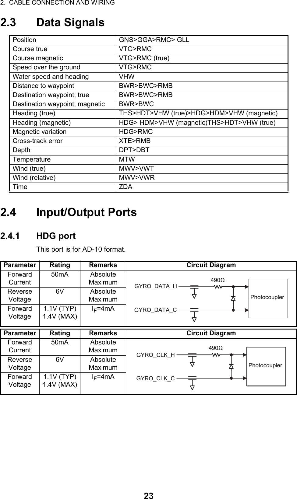
![253. EQUIPMENT SETTINGS3.1 Setting the LanguageAfter installation, on first power-up, select a language as follows:1. Press the /BRILL key to turn on the power."Now Initializing" appears and after a short time the window below appears.2. Use the CursorPad to select a language required and press the ENTER key.The window shown below appears.3. Select [Yes] and press the ENTER key.Language selectedLanguage English OK?YesNo](https://usermanual.wiki/Furuno-USA/9ZWRTR088B.User-Manual-I-Part-2/User-Guide-2264463-Page-6.png)
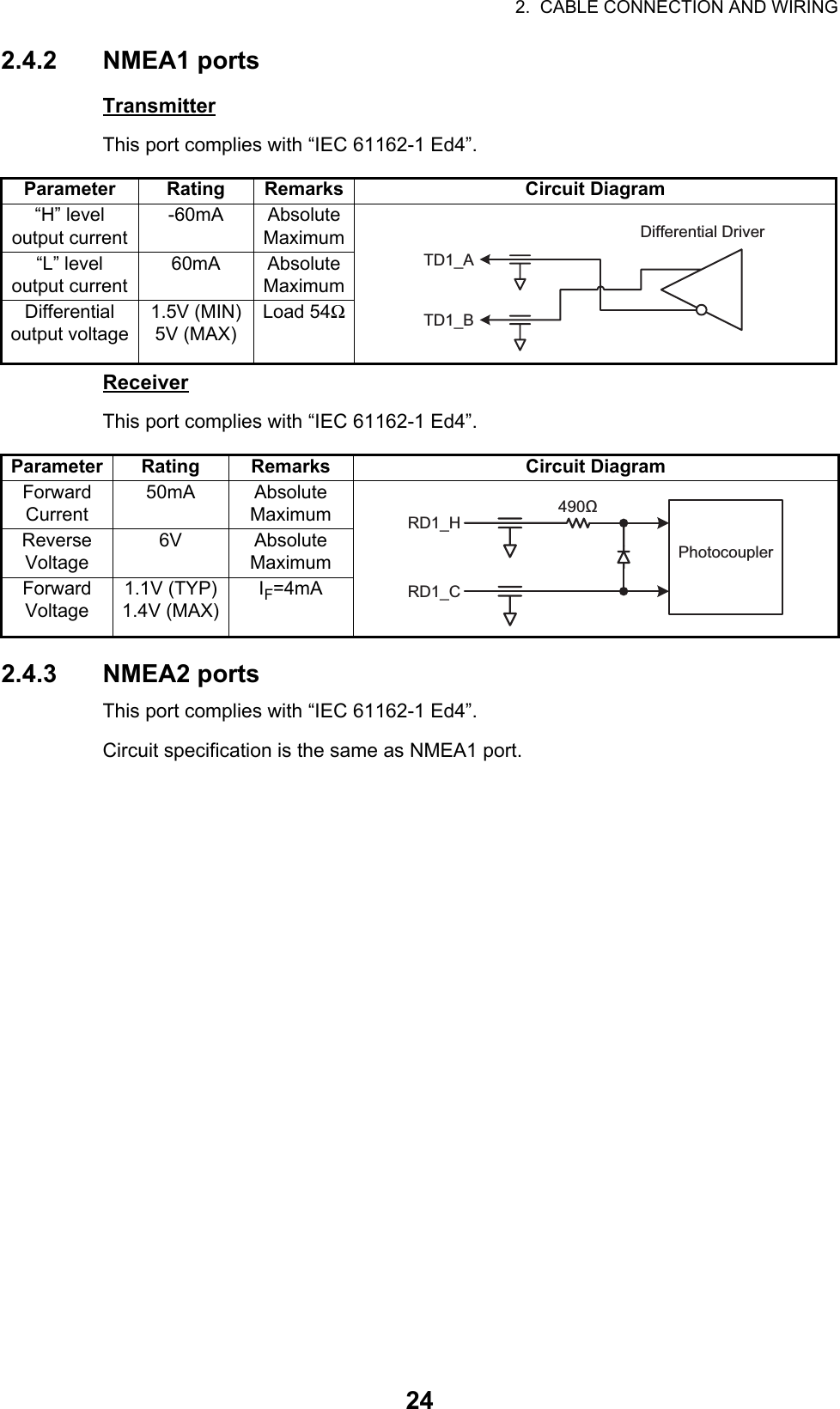
![3. EQUIPMENT SETTINGS263.2 How to Set the Purpose1. Press the MENU key. The main menu will appear on the screen.2. Press the S or T button to select [Factory]. The factory menu title bar will appear in gray color right side of the screen.3. Hold down the CANCEL/HL OFF key and press the MENU key five times to acti-vate the [Factory] menu.4. Press the ENTER key. The [Factory] menu becomes active and the cursor moves to the right-hand column.5. Press S or T to select [Purpose].6. Press the ENTER key to show the setting window.7. Press S or T to select the purpose required.8. Press the ENTER key to set the purpose.9. Press the CANCEL/HL OFF key to return to the main menu.Menu FactoryLanguagePurposePurposeModel: English: Sea: 8065 RTR-085AThe model name depends on your radar model. Do not change the model name.ARPAAISGPSSystem[Enter]: Enter [CANCEL/HL OFF]: Back[Menu]: ExitUse this menu when setting up in factoryInitialTestsSector BlanksUnitsInstallationFactoryRiverSeaIECRussian River](https://usermanual.wiki/Furuno-USA/9ZWRTR088B.User-Manual-I-Part-2/User-Guide-2264463-Page-7.png)
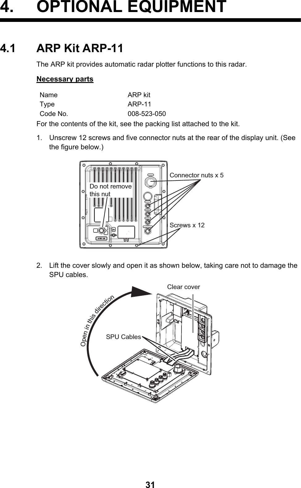
![3. EQUIPMENT SETTINGS273.3 How to Enter Initial SettingsAfter you complete setting the radar purpose, enter the Initial Settings as follows:1. On the main menu, press S or T to select [Installation].2. Press the ENTER key. The [Installation] menu becomes active and the cursor moves to the right-hand column.3. Press S or T to select an item from the [Installation] menu.4. Press the ENTER key to show the settings window.5. Press S or T to select an option.6. Press the ENTER key to set the option.7. Press the MENU key to close the main menu.Page 1Page 2 (Displayed when scrolled down)MenuARPAAISGPSSystemInitialTestsSector BlanksUnitsFactoryInstallationMenuARPAAISGPSSystemInitialTestsSector BlanksUnitsFactoryInstallationInstallationInput SourceARPA QV SelectDemo ModeAntenna RotationAntenna HeightNear STC LevelA/C Auto AdjustHeading AdjustTiming Adjust: Master: Off: Off: Rotate: 15m: 2: 0: 0.0°: 0.00 NM[ENTER]: Enter [CANCEL/HL OFF]: Back[MENU]: ExitUse this menu when installing on siteMBS AdjustVideo Init AdjustARPA Adjust SPARPA Adjust LPARPA Adjust MPAuto Install SetupTotal On TimeTotal TX TimeMemory Clear[ENTER]: Enter [CANCEL/HL OFF]: Back[MENU]: ExitRestoring the default settingsSet the [Sector Blank] to [Off] in order to execute [Auto Installation Setup] in the [Installation] menu.](https://usermanual.wiki/Furuno-USA/9ZWRTR088B.User-Manual-I-Part-2/User-Guide-2264463-Page-8.png)
![3. EQUIPMENT SETTINGS28Basic settings[Input source]: Select the input source from [Master] and [Slave]. The default setting is [Master].[ARPA QV Select]: Set to [On] to display quantized video on the screen. Set to [Off] for normal use.[Demo Mode]: Set to [On] to active demo mode. Set to [Off] for normal use.[Antenna Rotation]: [Rotate] (default setting) transmits the radar pulses by rotating the antenna. [Stop] transmits the radar pulses without rotating the antenna.[Antenna Height]: Set the height of the antenna above the water surface. The options are 5, 10, 15, 20, 30, 40 and 50m. The default setting is 15m.[Near STC level]: Set the STC curve to a near distance. The options are 1, 2, 3 and 4. “4” has the strongest effect.[A/C Auto Adjust]: Adjust the performance of the automatic A/C.[Memory Clear]: Restore the default settings. [Purpose], [Type] and [Source] are not changed. When turning on the power after a memory clear, the language selection window appears. (See page 25.)Heading adjustmentEnsure you have installed the antenna unit correctly, so that the unit faces towards the bow of the ship. A target at the front of the ship, aligned with the bow, must appear on the heading line (zero degrees). If the target does not appear on the heading line, fol-low the procedure below to adjust the heading.1. Set the ship toward an acceptable target (for example, a ship at anchor or a buoy) at a range between 0.125 and 0.25 nautical miles.2. Transmit the radar at a range setting of 0.25 nautical miles and measure the bear-ing of that target relative to the ship using an EBL.3. Open the [Installation] menu and select [Heading Adjust].4. Press the ENTER key to show the setting window for [Heading Adjust]. (See figure below)5. Press S or T to set the value measured in step 2. Check that the target appears on the heading line. If necessary repeat steps 1 to 5.6. Press ENTER to complete the adjustment.Master The display unit operates as the main radar.Slave The display unit operates as a remote display. For remote displays, adjust the [Video Init Adjust] and [Timing Adjust].(See page 30 and page 29, respectively.)0.0°(0.0°~359.9°)](https://usermanual.wiki/Furuno-USA/9ZWRTR088B.User-Manual-I-Part-2/User-Guide-2264463-Page-9.png)
![3. EQUIPMENT SETTINGS29How to automatically set the equipmentThe equipment can automatically adjust the tuning, timing and video.Note: Before you proceed, transmit the radar for more than 10 minutes on a long range and ensure [Sector Blank] is set to [OFF].1. Transmit on the maximum range.2. Select [Auto Install Setup] from the [Installation] menu and press ENTER.The tuning adjustment begins automatically and the message "Tuning adjusting" ap-pears during the tuning adjustment stage. After the tuning adjustment is complete, the timing and video are adjusted, in that order. The messages "Timing adjusting" and "Video adjusting" will appear during those stages of the [Auto Install Setup]. After all the adjustments are completed, the window disappears.Note: If any of the results require adjustment for your conditions, use the manual ad-justment procedures below to manually adjust them.Manual timing adjustmentThis adjustment gives correct radar performance on short ranges. The radar mea-sures the time required for a transmitted echo to go to the target and return to the source. The received echo appears on the display according to the measured time. The sweep must start from the center of the display.A trigger pulse created in the display unit goes to the antenna unit through the signal cable to activate the transmitter (magnetron). The time taken by the signal to move to the antenna unit changes, according to the length of the signal cable. During this pe-riod, the display unit must wait before the radar starts the sweep. When the display unit is not adjusted correctly, the echoes from a straight object will not appear as a straight line. The target appears "pushed" or "pulled" near the picture center. The ranges to objects are also shown at wrong distances. Below are examples of wrong and correct sweep timings.1. Transmit on the shortest range, then adjust the gain and the A/C SEA.2. Visibly select a target that creates a straight single line, such as harbor walls or straight piers.3. Open the [Installation] menu and select [Timing Adjust].4. Press ENTER to show the setting window.5. Press S or T to until the target selected in step 2 is shown as a straight line.6. Press ENTER to complete the adjustments.(1) Target pulled(2) Correct(3) Target pushed outward](https://usermanual.wiki/Furuno-USA/9ZWRTR088B.User-Manual-I-Part-2/User-Guide-2264463-Page-10.png)
![3. EQUIPMENT SETTINGS30Manual MBS adjustmentReduce the main bang (black hole), which appears at the display on short ranges, as follows:1. Transmit the radar on the shortest range.2. Open the [Installation] menu and select [MBS Adjust].3. Press ENTER to show the setting window.4. Use the S or T to adjust the main bang (between 0 and 25).5. Press ENTER to finish.Manual video adjustmentUse the following procedure to manually adjust the video settings if necessary:1. Transmit the radar and adjust the following settings:2. Open the [Installation] menu and select [Video Init Adjust].3. Press ENTER to show the setting window.4. Press S or T to adjust the white noise on the display. The setting range is 0 to 31. A larger value increases the gain.5. Press ENTER to finish.Note: If the display is used as a remote display, set [Input Source] to [Slave]. follow the above procedure to adjust the video and take care to ensure the remote display output is similar to the master display output.ARPA adjustmentDuring the sea trial, adjust the threshold level of the ARPA for short pulse, middle pulse and long pulse.• Default setting is 2.• If the ship echoes are difficult to acquire at setting level 2, adjust to level 1.• If the ARPA symbol moves to a different echo at setting level 2, adjust to level 3.Gain 85 to 90A/C Sea zeroA/C Rain zeroEcho Average OFFNoise Rejector OFFInterference Rejector 2](https://usermanual.wiki/Furuno-USA/9ZWRTR088B.User-Manual-I-Part-2/User-Guide-2264463-Page-11.png)

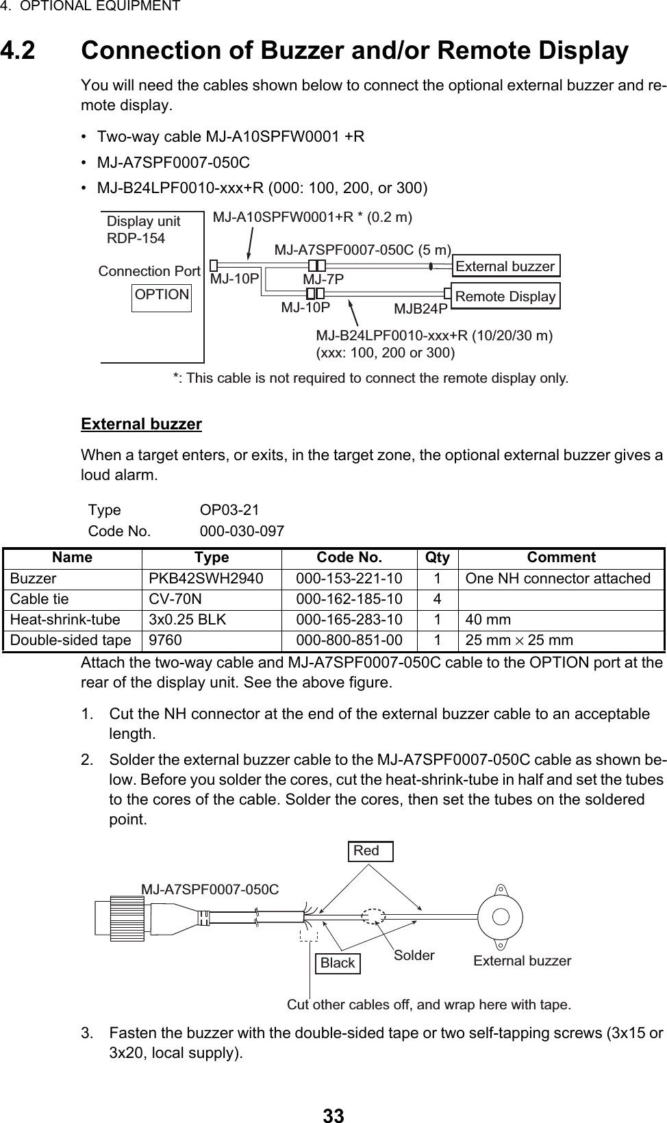
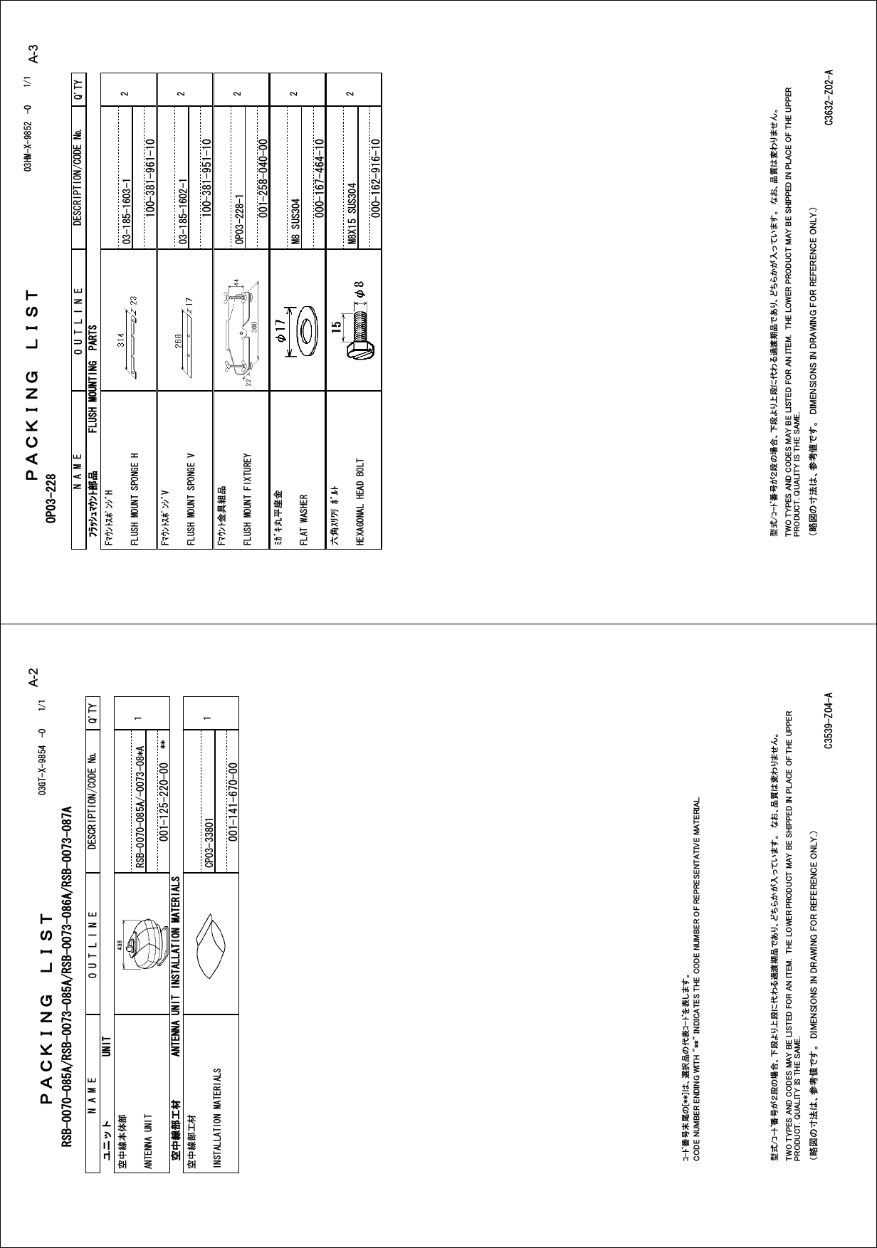
![NAME OUTLINE Q'TYDESCRIPTION/CODE №PACKING LIST03HM-X-9851 -0 RDP-1541/1NAME OUTLINE Q'TYDESCRIPTION/CODE №ユニット UNIT指示部DISPLAY UNIT1**RDP-154-*000-024-819-00予備品 SPARE PARTS予備品SPARE PARTS1SP03-17701001-258-000-00付属品 ACCESSORIES付属品ACCESSORIES1FP03-12301001-258-020-00工事材料 INSTALLATION MATERIALSケーブル組品MJCABLE ASSY.1MJ-A3SPF0017-050ZC000-157-995-10工事材料INSTALLATION MATERIALS1CP03-35601001-258-010-00図書 DOCUMENT取扱説明書(和)OPERATOR'S MANUAL (JP)1(*1)OMJ-36320-*000-178-501-1*取扱説明書(英)OPERATOR'S MANUAL (EN)1(*2)OME-36320-*000-178-502-1*取扱説明書(中)OPERATOR'S MANUAL (CN)1(*3)OZS-36320-*000-178-511-1*操作要領書(和)OPERATOR'S GUIDE (JP)1(*1)OSJ-36320-*000-178-503-1*操作要領書(多言語)OPERATOR'S GUIDE (MLG)1(*2)MLG-36320-*000-178-505-1*操作要領書(中)OPERATOR'S GUIDE (CN)1(*3)NZS-36320-*000-178-504-1*装備要領書(和)INSTALLATION MANUAL (JP)1(*1)IMJ-36320-*000-178-506-1*装備要領書(英)INSTALLATION MANUAL (EN)1(*2)IME-36320-*000-178-507-1*装備要領書(中)INSTALLATION MANUAL (CN)1(*3)IZS-36320-*000-178-512-1*フラッシュマウント型紙FLUSH MOUNTING TEMPLATE1C32-01308-*000-178-509-1*1.コ-ド番号末尾の[**]は、選択品の代表コードを表します。1.CODE NUMBER ENDING WITH "**" INDICATES THE CODE NUMBER OF REPRESENTATIVE MATERIAL.2.(*1)の書類は、和文仕様専用2.(*1) MARKED DOCUMENTS ARE FOR JAPANESE SET ONLY.3.(*2)の書類は、英文仕様専用3.(*2) MARKED DOCUMENTS ARE FOR ENGLISH SET ONLY.4.(*3)の書類は、中文仕様専用4.(*3) MARKED DOCUMENTS ARE FOR CHINESE SET ONLY.(略図の寸法は、参考値です。 DIMENSIONS IN DRAWING FOR REFERENCE ONLY.) 型式/コード番号が2段の場合、下段より上段に代わる過渡期品であり、どちらかが入っています。 なお、品質は変わりません。TWO TYPES AND CODES MAY BE LISTED FOR AN ITEM. THE LOWER PRODUCT MAY BE SHIPPED IN PLACE OF THE UPPER PRODUCT. QUALITY IS THE SAME.C3632-Z01-AA-1](https://usermanual.wiki/Furuno-USA/9ZWRTR088B.User-Manual-I-Part-2/User-Guide-2264463-Page-15.png)