Furuno USA 9ZWRTR088B Transceiver for Radar model FR-8045 User Manual
Furuno USA Inc Transceiver for Radar model FR-8045
Contents
User Manual I Part 2
20
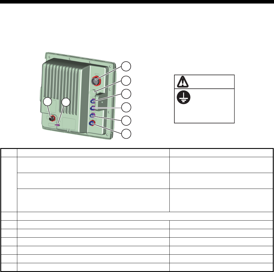
2. CABLE CONNECTION
AND WIRING
2.1 Standard Connection
Connect all necessary cables, using the figure and table below for reference.
No. Description Cable Required
1
Antenna cable to antenna unit (FR-8045) MJ-B24LPF0005-*+R
*: 50/100/150/200/300
Antenna cable to antenna unit. (FR-8065/8125) MJ-B24LPF0012-*+R
*: 100/150/200/300
Antenna cable to antenna unit. (FR-8255)
• MJ-B24LPF0011-050+R
• RW-9771 (10m, 15m, 20m, 30m)
• VL3P-VV-S2X2C-AA050
2 USB (Used by service man only).
3 Heading Sensor. (AD-10 format) (MJ-A6SPF0007-100C)
4 NMEA1 input/output. (Navigational equipment) (MJ-A7SPF0007-050C)
5 NMEA2 input/output. (Navigational equipment) (MJ-A7SPF0007-050C)
6 Option. (External buzzer, Remote display) (See section 4.2 for cabling.)
7 Power in. To ship’s power (pos = white, neg = black) (MJ-A3SPF0017-050ZC)
8 Grounding. Connect from here to ship’s terminal. IV-2sq.
Ground the
equipment to
prevent
interference.
CAUTION
1
2
3
4
5
6
78
2. CABLE CONNECTION AND WIRING
21
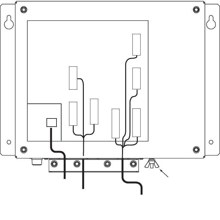
2.2 Wiring the Power Supply Unit (FR-8255 only)
2.2.1 Cabling
1. Unfasten four screws to remove the cable clamp.
2. Unfasten four screws to remove the cover.
3. Attach the connectors of three cables as shown in the figure below.
4. Lay three cables in respective slots referring to the figure above.
5. Reattach the cover and the cable clamp.
6. Connect a ground wire (local supply, IV-2sq) between the ground terminal and
ship’s ground.
POWER Board 03P9419
J1 3P
VL3P-VV-S2X
2C-AA050
cable
(to 12-24 VDC)
MJ-B24
LPF0011-050
cable
(to display unit)
V
H
9
N
H
13
V
H
4
J3
J4
J5
Ground
terminal
V
H
1
0
J12
N
H
1
4
J14
V
H
5
J13
V
H
2
J11
Antenna cable
RW-9771
(03S9771)
2. CABLE CONNECTION AND WIRING
22
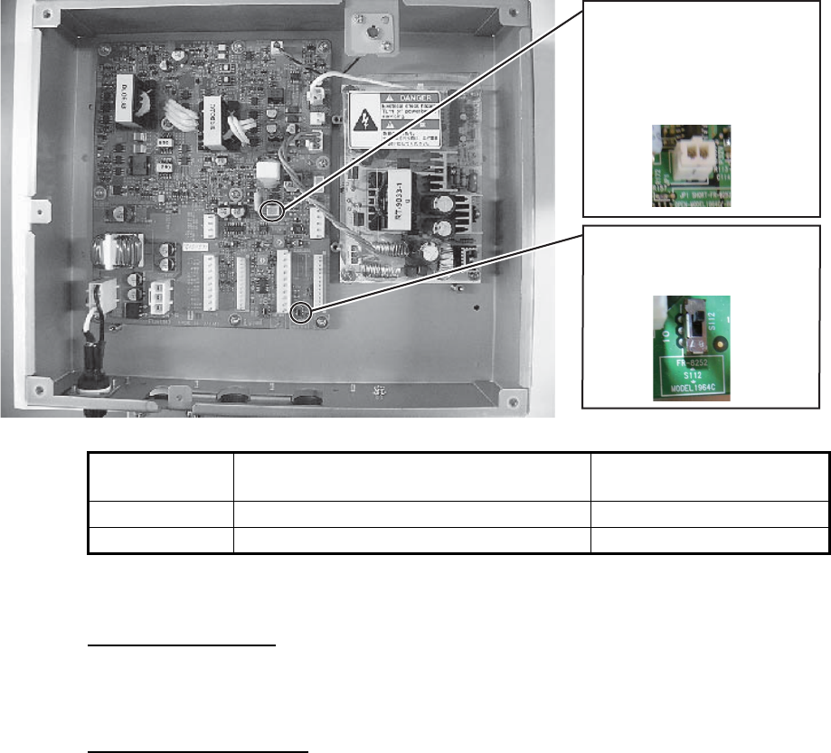
2.2.2 Jumper block, slide switch setting
The jumper block JP1 and slide switch S112 on the PWR board (03P9419) must be
set according to radar model. Open the unit, locate JP1 and S112 and set them as
below.
2.2.3 Power requirement, replacement of fuses
Power requirement
The power for the power supply unit and display unit must be drawn from the same
power switch on the power terminal board.
Replacement of fuses
The power supply unit is shipped with a 15 A fuse(for connection to 12 VDC battery).
Replace the fuse with a 7 A (supplied) when the ship’s battery is 24 VDC.
Jumper block,
slide switch Function Setting
JP1 Enables/disables motor slow start circuit. Short (disable)
S112 TUNE voltage selector (0-12 V, 0-32 V) Upward position (0-12 V)
Jumper block JP1
("short" for FR-8255 radar;
remove dummy connector
and attach connector
assy. XH2P-L40-ACR.)
Slide switch S112
(Set to upward position
for “FR-8252”)
2. CABLE CONNECTION AND WIRING
23
2.3 Data Signals
2.4 Input/Output Ports
2.4.1 HDG port
This port is for AD-10 format.
Position GNS>GGA>RMC> GLL
Course true VTG>RMC
Course magnetic VTG>RMC (true)
Speed over the ground VTG>RMC
Water speed and heading VHW
Distance to waypoint BWR>BWC>RMB
Destination waypoint, true BWR>BWC>RMB
Destination waypoint, magnetic BWR>BWC
Heading (true) THS>HDT>VHW (true)>HDG>HDM>VHW (magnetic)
Heading (magnetic) HDG> HDM>VHW (magnetic)THS>HDT>VHW (true)
Magnetic variation HDG>RMC
Cross-track error XTE>RMB
Depth DPT>DBT
Temperature MTW
Wind (true) MWV>VWT
Wind (relative) MWV>VWR
Time ZDA
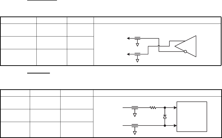
Parameter Rating Remarks Circuit Diagram
Forward
Current
50mA Absolute
Maximum
Reverse
Voltage
6V Absolute
Maximum
Forward
Voltage
1.1V (TYP)
1.4V (MAX)
IF=4mA
Parameter Rating Remarks Circuit Diagram
Forward
Current
50mA Absolute
Maximum
Reverse
Voltage
6V Absolute
Maximum
Forward
Voltage
1.1V (TYP)
1.4V (MAX)
IF=4mA
Photocoupler
490Ω
GYRO_DATA_H
GYRO_DATA_C
Photocoupler
490Ω
GYRO_CLK_H
GYRO_CLK_C
2. CABLE CONNECTION AND WIRING
24
2.4.2 NMEA1 ports
Transmitter
This port complies with “IEC 61162-1 Ed4”.
Receiver
This port complies with “IEC 61162-1 Ed4”.
2.4.3 NMEA2 ports
This port complies with “IEC 61162-1 Ed4”.
Circuit specification is the same as NMEA1 port.
Parameter Rating Remarks Circuit Diagram
“H” level
output current
-60mA Absolute
Maximum
“L” level
output current
60mA Absolute
Maximum
Differential
output voltage
1.5V (MIN)
5V (MAX)
Load 54Ω
Parameter Rating Remarks Circuit Diagram
Forward
Current
50mA Absolute
Maximum
Reverse
Voltage
6V Absolute
Maximum
Forward
Voltage
1.1V (TYP)
1.4V (MAX)
IF=4mA
Differential Driver
TD1_A
TD1_B
Photocoupler
490Ω
RD1_H
RD1_C
25
3. EQUIPMENT SETTINGS
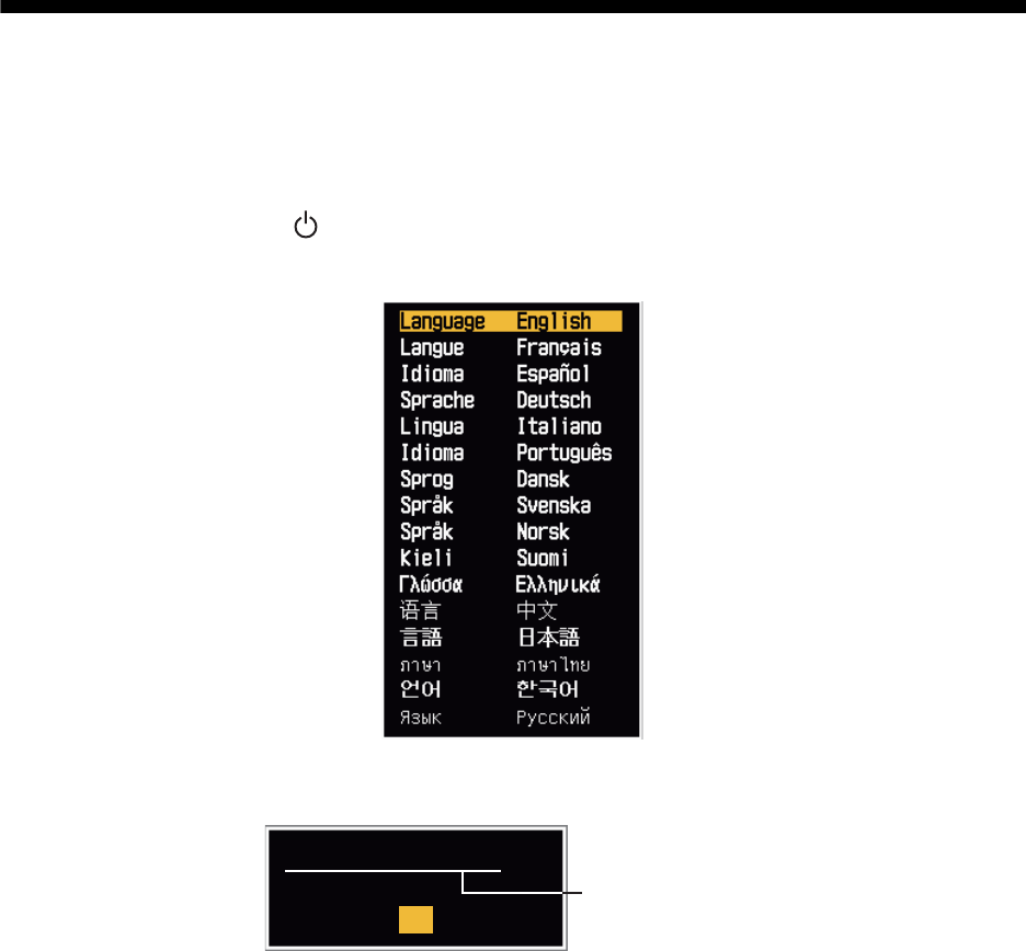
3.1 Setting the Language
After installation, on first power-up, select a language as follows:
1. Press the /BRILL key to turn on the power.
"Now Initializing" appears and after a short time the window below appears.
2. Use the CursorPad to select a language required and press the ENTER key.
The window shown below appears.
3. Select [Yes] and press the ENTER key.
Language selected
Language English OK?
Yes
No

3. EQUIPMENT SETTINGS
26
3.2 How to Set the Purpose
1. Press the MENU key. The main menu will appear on the screen.
2. Press the S or T button to select [Factory]. The factory menu title bar will appear
in gray color right side of the screen.
3. Hold down the CANCEL/HL OFF key and press the MENU key five times to acti-
vate the [Factory] menu.
4. Press the ENTER key. The [Factory] menu becomes active and the cursor moves
to the right-hand column.
5. Press S or T to select [Purpose].
6. Press the ENTER key to show the setting window.
7. Press S or T to select the purpose required.
8. Press the ENTER key to set the purpose.
9. Press the CANCEL/HL OFF key to return to the main menu.
Menu Factory
Language
Purpose
Purpose
Model
: English
: Sea
: 8065 RTR-085A
The model name depends on your radar model.
Do not change the model name.
ARPA
AIS
GPS
System
[Enter]: Enter [CANCEL/HL OFF]: Back
[Menu]: Exit
Use this menu when setting up in factory
Initial
Tests
Sector Blanks
Units
Installation
Factory
River
Sea
IEC
Russian River
3. EQUIPMENT SETTINGS
27
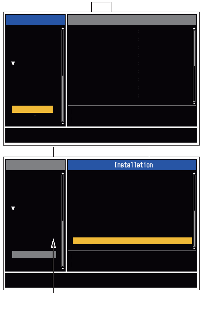
3.3 How to Enter Initial Settings
After you complete setting the radar purpose, enter the Initial Settings as follows:
1. On the main menu, press S or T to select [Installation].
2. Press the ENTER key. The [Installation] menu becomes active and the cursor
moves to the right-hand column.
3. Press S or T to select an item from the [Installation] menu.
4. Press the ENTER key to show the settings window.
5. Press S or T to select an option.
6. Press the ENTER key to set the option.
7. Press the MENU key to close the main menu.
Page 1
Page 2 (Displayed when scrolled down)
Menu
ARPA
AIS
GPS
System
Initial
Tests
Sector Blanks
Units
Factory
Installation
Menu
ARPA
AIS
GPS
System
Initial
Tests
Sector Blanks
Units
Factory
Installation
Installation
Input Source
ARPA QV Select
Demo Mode
Antenna Rotation
Antenna Height
Near STC Level
A/C Auto Adjust
Heading Adjust
Timing Adjust
: Master
: Off
: Off
: Rotate
: 15m
: 2
: 0
: 0.0°
: 0.00 NM
[ENTER]: Enter [CANCEL/HL OFF]: Back
[MENU]: Exit
Use this menu when installing on site
MBS Adjust
Video Init Adjust
ARPA Adjust SP
ARPA Adjust LP
ARPA Adjust MP
Auto Install Setup
Total On Time
Total TX Time
Memory Clear
[ENTER]: Enter [CANCEL/HL OFF]: Back
[MENU]: Exit
Restoring the default settings
Set the [Sector Blank] to [Off] in order to
execute [Auto Installation Setup] in the
[Installation] menu.

3. EQUIPMENT SETTINGS
28
Basic settings
[Input source]: Select the input source from [Master] and [Slave]. The default setting
is [Master].
[ARPA QV Select]: Set to [On] to display quantized video on the screen. Set to [Off]
for normal use.
[Demo Mode]: Set to [On] to active demo mode. Set to [Off] for normal use.
[Antenna Rotation]: [Rotate] (default setting) transmits the radar pulses by rotating
the antenna. [Stop] transmits the radar pulses without rotating the antenna.
[Antenna Height]: Set the height of the antenna above the water surface. The options
are 5, 10, 15, 20, 30, 40 and 50m. The default setting is 15m.
[Near STC level]: Set the STC curve to a near distance. The options are 1, 2, 3 and
4. “4” has the strongest effect.
[A/C Auto Adjust]: Adjust the performance of the automatic A/C.
[Memory Clear]: Restore the default settings. [Purpose], [Type] and [Source] are not
changed. When turning on the power after a memory clear, the language selection
window appears. (See page 25.)
Heading adjustment
Ensure you have installed the antenna unit correctly, so that the unit faces towards the
bow of the ship. A target at the front of the ship, aligned with the bow, must appear on
the heading line (zero degrees). If the target does not appear on the heading line, fol-
low the procedure below to adjust the heading.
1. Set the ship toward an acceptable target (for example, a ship at anchor or a buoy)
at a range between 0.125 and 0.25 nautical miles.
2. Transmit the radar at a range setting of 0.25 nautical miles and measure the bear-
ing of that target relative to the ship using an EBL.
3. Open the [Installation] menu and select [Heading Adjust].
4. Press the ENTER key to show the setting window for [Heading Adjust]. (See figure
below)
5. Press S or T to set the value measured in step 2. Check that the target appears
on the heading line. If necessary repeat steps 1 to 5.
6. Press ENTER to complete the adjustment.
Master The display unit operates as the main radar.
Slave The display unit operates as a remote display. For remote displays, adjust
the [Video Init Adjust] and [Timing Adjust].
(See page 30 and page 29, respectively.)
0.0°
(0.0°~359.9°)

3. EQUIPMENT SETTINGS
29
How to automatically set the equipment
The equipment can automatically adjust the tuning, timing and video.
Note: Before you proceed, transmit the radar for more than 10 minutes on a long
range and ensure [Sector Blank] is set to [OFF].
1. Transmit on the maximum range.
2. Select [Auto Install Setup] from the [Installation] menu and press ENTER.
The tuning adjustment begins automatically and the message "Tuning adjusting" ap-
pears during the tuning adjustment stage. After the tuning adjustment is complete, the
timing and video are adjusted, in that order. The messages "Timing adjusting" and
"Video adjusting" will appear during those stages of the [Auto Install Setup]. After all
the adjustments are completed, the window disappears.
Note: If any of the results require adjustment for your conditions, use the manual ad-
justment procedures below to manually adjust them.
Manual timing adjustment
This adjustment gives correct radar performance on short ranges. The radar mea-
sures the time required for a transmitted echo to go to the target and return to the
source. The received echo appears on the display according to the measured time.
The sweep must start from the center of the display.
A trigger pulse created in the display unit goes to the antenna unit through the signal
cable to activate the transmitter (magnetron). The time taken by the signal to move to
the antenna unit changes, according to the length of the signal cable. During this pe-
riod, the display unit must wait before the radar starts the sweep. When the display
unit is not adjusted correctly, the echoes from a straight object will not appear as a
straight line. The target appears "pushed" or "pulled" near the picture center. The
ranges to objects are also shown at wrong distances. Below are examples of wrong
and correct sweep timings.
1. Transmit on the shortest range, then adjust the gain and the A/C SEA.
2. Visibly select a target that creates a straight single line, such as harbor walls or
straight piers.
3. Open the [Installation] menu and select [Timing Adjust].
4. Press ENTER to show the setting window.
5. Press S or T to until the target selected in step 2 is shown as a straight line.
6. Press ENTER to complete the adjustments.
(1) Target pulled
(2) Correct
(3) Target pushed outward

3. EQUIPMENT SETTINGS
30
Manual MBS adjustment
Reduce the main bang (black hole), which appears at the display on short ranges, as
follows:
1. Transmit the radar on the shortest range.
2. Open the [Installation] menu and select [MBS Adjust].
3. Press ENTER to show the setting window.
4. Use the S or T to adjust the main bang (between 0 and 25).
5. Press ENTER to finish.
Manual video adjustment
Use the following procedure to manually adjust the video settings if necessary:
1. Transmit the radar and adjust the following settings:
2. Open the [Installation] menu and select [Video Init Adjust].
3. Press ENTER to show the setting window.
4. Press S or T to adjust the white noise on the display. The setting range is 0 to
31. A larger value increases the gain.
5. Press ENTER to finish.
Note: If the display is used as a remote display, set [Input Source] to [Slave]. follow
the above procedure to adjust the video and take care to ensure the remote display
output is similar to the master display output.
ARPA adjustment
During the sea trial, adjust the threshold level of the ARPA for short pulse, middle
pulse and long pulse.
• Default setting is 2.
• If the ship echoes are difficult to acquire at setting level 2, adjust to level 1.
• If the ARPA symbol moves to a different echo at setting level 2, adjust to level 3.
Gain 85 to 90
A/C Sea zero
A/C Rain zero
Echo Average OFF
Noise Rejector OFF
Interference Rejector 2
31
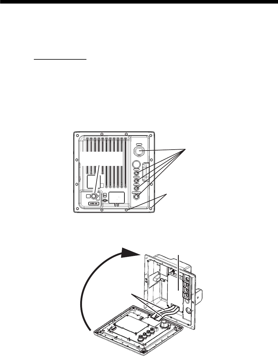
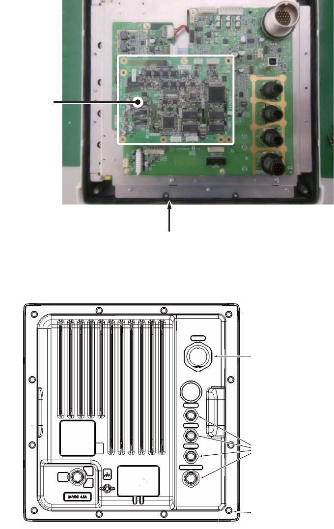
4. OPTIONAL EQUIPMENT
4.1 ARP Kit ARP-11
The ARP kit provides automatic radar plotter functions to this radar.
Necessary parts
For the contents of the kit, see the packing list attached to the kit.
1. Unscrew 12 screws and five connector nuts at the rear of the display unit. (See
the figure below.)
2. Lift the cover slowly and open it as shown below, taking care not to damage the
SPU cables.
Name ARP kit
Type ARP-11
Code No. 008-523-050
Connector nuts x 5
Do not remove
this nut
Screws x 12
SPU Cables
Clear cover
O
p
e
n
i
n
t
h
i
s
d
i
r
e
c
t
i
o
n
4. OPTIONAL EQUIPMENT
32
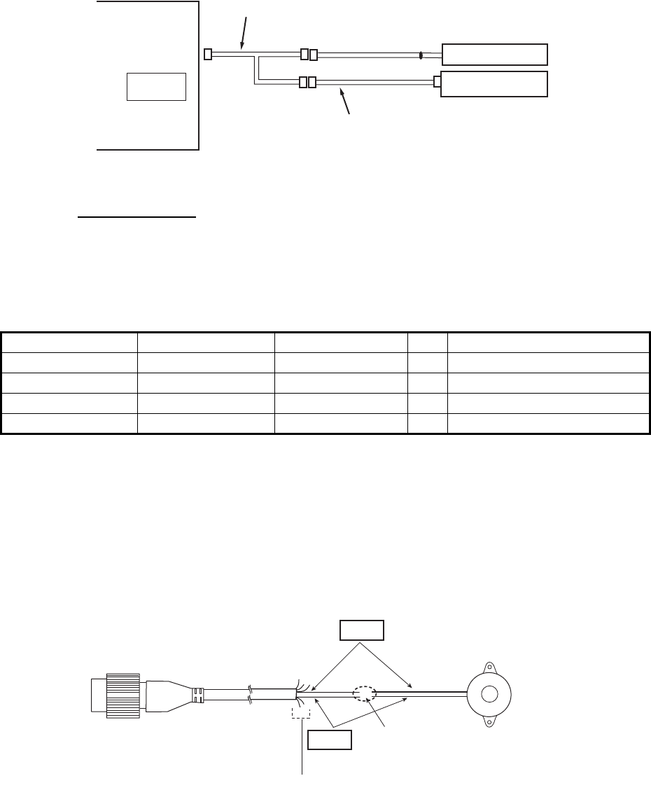
3. Mate P107 on the ARP Circuit-board with J214 on the 03P9586 Board and fasten
with four screws.
4. Reassemble the display unit, taking care not to exceed the torque requirements
for each connector nut. (See the figure below for nut torque.)
A
RP board
Confirm that the rubber gasket is set
securely in the groove around the panel.
Torque
2.94±0.29 Nm
Torque
0.78±0.08 Nm
Torque
0.78±0.08 Nm
(12 pcs)
4. OPTIONAL EQUIPMENT
33
4.2 Connection of Buzzer and/or Remote Display
You will need the cables shown below to connect the optional external buzzer and re-
mote display.
• Two-way cable MJ-A10SPFW0001 +R
• MJ-A7SPF0007-050C
• MJ-B24LPF0010-xxx+R (000: 100, 200, or 300)
External buzzer
When a target enters, or exits, in the target zone, the optional external buzzer gives a
loud alarm.
Attach the two-way cable and MJ-A7SPF0007-050C cable to the OPTION port at the
rear of the display unit. See the above figure.
1. Cut the NH connector at the end of the external buzzer cable to an acceptable
length.
2. Solder the external buzzer cable to the MJ-A7SPF0007-050C cable as shown be-
low. Before you solder the cores, cut the heat-shrink-tube in half and set the tubes
to the cores of the cable. Solder the cores, then set the tubes on the soldered
point.
3. Fasten the buzzer with the double-sided tape or two self-tapping screws (3x15 or
3x20, local supply).
Type OP03-21
Code No. 000-030-097
Name Type Code No. Qty Comment
Buzzer PKB42SWH2940 000-153-221-10 1 One NH connector attached
Cable tie CV-70N 000-162-185-10 4
Heat-shrink-tube 3x0.25 BLK 000-165-283-10 1 40 mm
Double-sided tape 9760 000-800-851-00 1 25 mm × 25 mm
OPTION Remote Display
External buzzer
MJ-A7SPF0007-050C (5 m)
MJ-10P
MJ-10P MJ-7P
MJB24P
Display unit
RDP-154
Connection Port
MJ-A10SPFW0001+R * (0.2 m)
MJ-B24LPF0010-xxx+R (10/20/30 m)
(xxx: 100, 200 or 300)
*: This cable is not required to connect the remote display only.
Red
Black External buzzer
MJ-A7SPF0007-050C
Solder
Cut other cables off, and wrap here with tape.
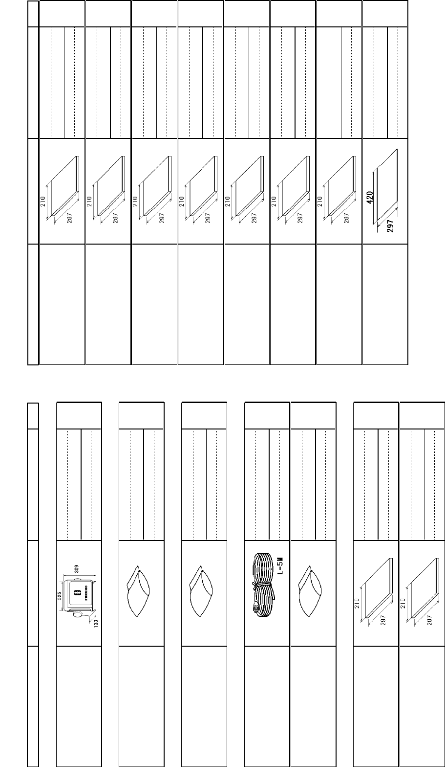
NAME OUTLINE Q'TYDESCRIPTION/CODE №
PACKING LIST
03HM-X-9851 -0
RDP-154
1/1
NAME OUTLINE Q'TYDESCRIPTION/CODE №
ユニット UNIT
指示部
DISPLAY UNIT
1
**
RDP-154-*
000-024-819-00
予備品 SPARE PARTS
予備品
SPARE PARTS
1
SP03-17701
001-258-000-00
付属品 ACCESSORIES
付属品
ACCESSORIES
1
FP03-12301
001-258-020-00
工事材料 INSTALLATION MATERIALS
ケーブル組品MJ
CABLE ASSY.
1
MJ-A3SPF0017-050ZC
000-157-995-10
工事材料
INSTALLATION MATERIALS
1
CP03-35601
001-258-010-00
図書 DOCUMENT
取扱説明書(和)
OPERATOR'S MANUAL (JP)
1
(*1)
OMJ-36320-*
000-178-501-1*
取扱説明書(英)
OPERATOR'S MANUAL (EN)
1
(*2)
OME-36320-*
000-178-502-1*
取扱説明書(中)
OPERATOR'S MANUAL (CN)
1
(*3)
OZS-36320-*
000-178-511-1*
操作要領書(和)
OPERATOR'S GUIDE (JP)
1
(*1)
OSJ-36320-*
000-178-503-1*
操作要領書(多言語)
OPERATOR'S GUIDE (MLG)
1
(*2)
MLG-36320-*
000-178-505-1*
操作要領書(中)
OPERATOR'S GUIDE (CN)
1
(*3)
NZS-36320-*
000-178-504-1*
装備要領書(和)
INSTALLATION MANUAL
(JP)
1
(*1)
IMJ-36320-*
000-178-506-1*
装備要領書(英)
INSTALLATION MANUAL
(EN)
1
(*2)
IME-36320-*
000-178-507-1*
装備要領書(中)
INSTALLATION MANUAL
(CN)
1
(*3)
IZS-36320-*
000-178-512-1*
フラッシュマウント型紙
FLUSH MOUNTING TEMPLATE
1
C32-01308-*
000-178-509-1*
1.コ-ド番号末尾の[**]は、選択品の代表コードを表します。
1.CODE NUMBER ENDING WITH "**" INDICATES THE CODE NUMBER OF REPRESENTATIVE MATERIAL.
2.(*1)の書類は、和文仕様専用
2.(*1) MARKED DOCUMENTS ARE FOR JAPANESE SET ONLY.
3.(*2)の書類は、英文仕様専用
3.(*2) MARKED DOCUMENTS ARE FOR ENGLISH SET ONLY.
4.(*3)の書類は、中文仕様専用
4.(*3) MARKED DOCUMENTS ARE FOR CHINESE SET ONLY.
(略図の寸法は、参考値です。 DIMENSIONS IN DRAWING FOR REFERENCE ONLY.)
型式/コード番号が2段の場合、下段より上段に代わる過渡期品であり、どちらかが入っています。 なお、品質は変わりません。
TWO TYPES AND CODES MAY BE LISTED FOR AN ITEM. THE LOWER PRODUCT MAY BE SHIPPED IN PLACE OF
THE UPPER PRODUCT. QUALITY IS THE SAME.
C3632-Z01-A
A-1
㧼㧭㧯㧷㧵㧺㧳ޓ㧸㧵㧿㨀
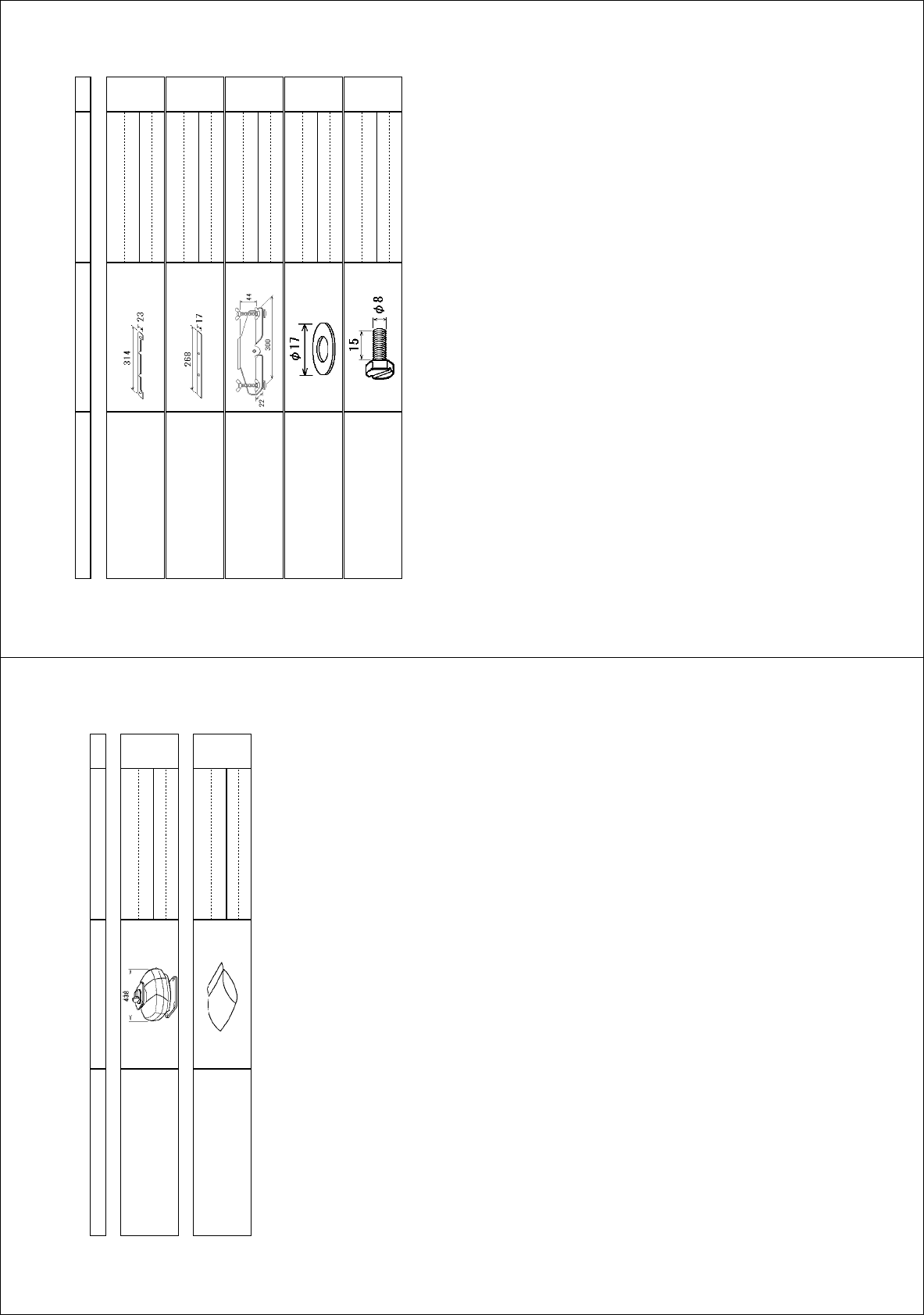
*/:
12
0#/' 176.+0' &'5%4+26+10%1&'ͳ 36;
㩖㩡㨹㩆㨷㩙㨽㩧㩎ㇱຠ (.75*/1706+0)ޓ2#465
(㩙㨽㩧㩎㩇㩘㩩㩧㩆㩨*
(.75*/17065210)'*
(㩙㨽㩧㩎㩇㩘㩩㩧㩆㩨8
(.75*/17065210)'8
(㩙㨽㩧㩎㊄ౕ⚵ຠ
(.75*/1706(+:674';
12
㩚㩀㩨㩁ਣᐔᐳ㊄
(.#69#5*'4
/575
ⷺ㩇㩢㩦㩢㩘㩨㩣㩎
*':#)10#.*'#&$1.6
/:575
䋨⇛࿑䈱ኸᴺ䈲䇮ෳ⠨୯䈪䈜䇯㩷㩷㪛㪠㪤㪜㪥㪪㪠㪦㪥㪪㩷㪠㪥㩷㪛㪩㪘㪮㪠㪥㪞㩷㪝㪦㪩㩷㪩㪜㪝㪜㪩㪜㪥㪚㪜㩷㪦㪥㪣㪰㪅䋩
ဳᑼ㪆䍘䍎䍢䍼⇟ภ䈏䋲Ბ䈱႐ว䇮ਅᲑ䉋䉍Ბ䈮ઍ䉒䉎ㆊᷰᦼຠ䈪䈅䉍䇮䈬䈤䉌䈎䈏䈦䈩䈇䉁䈜䇯䇭䈭䈍䇮ຠ⾰䈲ᄌ䉒䉍䉁䈞䉖䇯
㪫㪮㪦㩷㪫㪰㪧㪜㪪㩷㪘㪥㪛㩷㪚㪦㪛㪜㪪㩷㪤㪘㪰㩷㪙㪜㩷㪣㪠㪪㪫㪜㪛㩷㪝㪦㪩㩷㪘㪥㩷㪠㪫㪜㪤㪅㩷㩷㪫㪟㪜㩷㪣㪦㪮㪜㪩㩷㪧㪩㪦㪛㪬㪚㪫㩷㪤㪘㪰㩷㪙㪜㩷㪪㪟㪠㪧㪧㪜㪛㩷㪠㪥㩷㪧㪣㪘㪚㪜㩷㪦㪝㩷㪫㪟㪜㩷㪬㪧㪧㪜㪩㩷
㪧㪩㪦㪛㪬㪚㪫㪅㩷㪨㪬㪘㪣㪠㪫㪰㩷㪠㪪㩷㪫㪟㪜㩷㪪㪘㪤㪜㪅
%<#
A
-3
㧼㧭㧯㧷㧵㧺㧳ޓ㧸㧵㧿㨀
)6:
45$#45$#45$#45$#
0#/' 176.+0' &'5%4+26+10%1&'ͳ 36;
࡙࠾࠶࠻ 70+6
ⓨਛ✢ᧄㇱ
#06'00#70+6
45$##
ⓨਛ✢ㇱᎿ᧚ #06'00#70+6+056#..#6+10/#6'4+#.5
ⓨਛ✢ㇱᎿ᧚
+056#..#6+10/#6'4+#.5
%2
䍘㪄䍢䍼⇟ภᧃየ䈱㪲㪁㪁㪴䈲䇮ㆬᛯຠ䈱ઍ䍘䍎䍢䍼䉕䈚䉁䈜䇯
㪚㪦㪛㪜㩷㪥㪬㪤㪙㪜㪩㩷㪜㪥㪛㪠㪥㪞㩷㪮㪠㪫㪟㩷㩹㪁㪁㩹㩷㪠㪥㪛㪠㪚㪘㪫㪜㪪㩷㪫㪟㪜㩷㪚㪦㪛㪜㩷㪥㪬㪤㪙㪜㪩㩷㪦㪝㩷㪩㪜㪧㪩㪜㪪㪜㪥㪫㪘㪫㪠㪭㪜㩷㪤㪘㪫㪜㪩㪠㪘㪣㪅
䋨⇛࿑䈱ኸᴺ䈲䇮ෳ⠨୯䈪䈜䇯㩷㩷㪛㪠㪤㪜㪥㪪㪠㪦㪥㪪㩷㪠㪥㩷㪛㪩㪘㪮㪠㪥㪞㩷㪝㪦㪩㩷㪩㪜㪝㪜㪩㪜㪥㪚㪜㩷㪦㪥㪣㪰㪅䋩
ဳᑼ㪆䍘䍎䍢䍼⇟ภ䈏䋲Ბ䈱႐ว䇮ਅᲑ䉋䉍Ბ䈮ઍ䉒䉎ㆊᷰᦼຠ䈪䈅䉍䇮䈬䈤䉌䈎䈏䈦䈩䈇䉁䈜䇯䇭䈭䈍䇮ຠ⾰䈲ᄌ䉒䉍䉁䈞䉖䇯
㪫㪮㪦㩷㪫㪰㪧㪜㪪㩷㪘㪥㪛㩷㪚㪦㪛㪜㪪㩷㪤㪘㪰㩷㪙㪜㩷㪣㪠㪪㪫㪜㪛㩷㪝㪦㪩㩷㪘㪥㩷㪠㪫㪜㪤㪅㩷㩷㪫㪟㪜㩷㪣㪦㪮㪜㪩㩷㪧㪩㪦㪛㪬㪚㪫㩷㪤㪘㪰㩷㪙㪜㩷㪪㪟㪠㪧㪧㪜㪛㩷㪠㪥㩷㪧㪣㪘㪚㪜㩷㪦㪝㩷㪫㪟㪜㩷㪬㪧㪧㪜㪩㩷
㪧㪩㪦㪛㪬㪚㪫㪅㩷㪨㪬㪘㪣㪠㪫㪰㩷㪠㪪㩷㪫㪟㪜㩷㪪㪘㪤㪜㪅
%<#
A
-2
30/Oct/2013 H.MAKI
D-1
D-2
Y. Hatai
27/Nov/2013 H.MAKI
D-3
27/Nov/2013 H.MAKI
D-4
A
B
C
123 4
kg
名称
NAME
TITLE
MASS
SCALE
APPROVED
CHECKED
DRAWN
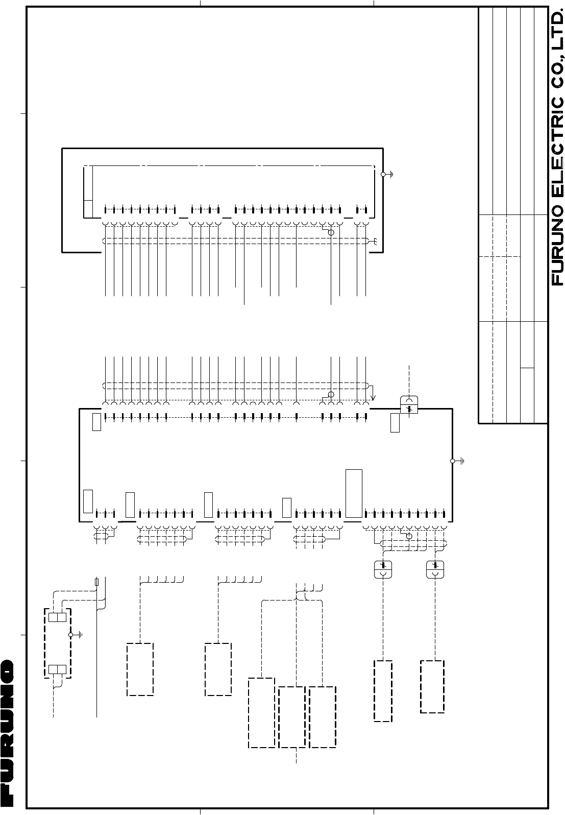
MARINE RADAR
INTERCONNECTION DIAGRAM
船舶用レーダー
相互結線図
T.YAMASAKI
DWG.No. REF.No.
H.MAKI
FR-8045
*2: OPTION.
*1: SHIPYARD SUPPLY.
*3: GROUND SHIELD EFFECTIVELY AT BOTH ENDS.
NOTE
注記
*1) 造船所手配。
*2) オプション。
*3) シールドは両端で完全にアースする。
03-185-6002-0
IV-2sq.
*1
1
2
3
4
5
6
NMEA1
MJ-A7SPF
7
GRN
YEL
WHT
キ
シロ
ミドリ
BLK
クロ
アカ RED
アオ BLU
航法装置
NAV EQUIPMENT
(NMEA0183) 5m,φ7
*2
1
2
3
4
5
6
MJ-A7SPF
7
GRN
YEL
WHT
キ
シロ
ミドリ
BLK
クロ
アカ RED
アオ BLU
航法装置
NAV EQUIPMENT
(NMEA0183) 5m,φ7
*2
HDG
MJ-A6SPF
1
2
3
4
5
6
MJ-A7SPF0007-050C
MJ-A7SPF0007-050C
NMEA2
RD1-C
RD1-H
TD1-B
TD1-A
SHIELD
SHIELD
TD2-A
TD2-B
RD2-H
RD2-C
キ
クロ
シロ
GRN
YEL
BLK
WHT
ミドリ
NC
ジャイロ A-D CONVERTER
A-Dコンバータ
AD-100
HEADING SENSOR
ヘディングセンサー
*2 MJ-A6SPF0003-050C/100C
5/10m,φ6
10m,φ6
MJ-A6SPF0007-100C
*2
サテライトコンパス
SATELLITE COMPASS
SC-50/100 *2 10m,φ6
MJ-A6SPF0007-100C
*2
*2
SHIELD
選択
SELECT
GYRO
*2PG-500/1000
GYRO_DATA-H
GYRO_DATA-C
GYRO_CLK-H
GYRO_CLK-C
1
2
3
4
NC
SHIELD
OP_TRIG
OP_BP
5
6
EXT_BUZZ_12V
EXT_BUZZER
10 OP_VIDEO_GND
7
8
9
OP_VIDEO
OP_HD
GND
MJA7SPF0007-050C,5m
MJ-A10SPF
W0001+R
10
7
MJ-B24LPF0010-**0+R
EXT. BUZZER
外部ブザー
*2
OP03-21
NMEA1_12V
NMEA1_GND
NMEA2_12V
NMEA2_GND
10
11
20
14
15
2
8
7
17
9
1
18
22
21
16
6
13
12
19
3
4
23
24
DJ-1
5
4
TYPE A
USB
PC FOR MAINTENANCE
パソコン(保守用)
MJ-B24LPF0005-**0+R,5/10/15/20/30m,φ11
(21C+2C2V)
ミドリ
アオ
チャ
チャ(太)
シロ(太)
アカ(太)
クロ(太)
キ(太)
GRN
BLU
BRN
BRN(B)
WHT(B)
RED(B)
BLK(B)
YEL(B)
クロ
ムラサキ(太)
BLK
PPL(B)
シロ
アオ(太)
WHT
BLU(B)
ドウジク COAX.
ミドリ(太)
ダイ(太)ORG(B)
アカ RED
キ YEL
PPLムラサキ
シロ/チャ WHT/BRN
シロ/アカ WHT/RED
ダイ ORG
シロ/ダイ WHT/ORG
*3
8
7
6
5
4
3
2
1
9
RTB
4
3
2
1
5
6
7
8
4
3
2
1
9
10
11
12
13
2
1
*3
-12V
GND
+12V
+12V
-12V
NC
BP
J821(VH9P)
J823(VH4P)
NC
MBS-L
NC
GND
NC
NC
GND
VIDEO
J822(VH2P)
RW-4747,0.3m
03P9249
TX_TRIG
PL-A
PL-B
MOTOR-H
HD
MOTOR-C
TUNE-IND
MOTOR-C
MOTOR-H
MOTOR-H
TUNE_CONT
-12V
+12V
J824(SH13P)
10/20/30m,φ11
EXT-BUZZ/
SUB DISPLAY
*2
副指示器
REMOTE DISPLAY
DISPLAY UNIT
指示部
RDP-154
シロ
クロ
WHT
BLK
MJ-A3SPF
3
2
1
POWER
GND
(-)
(+)
MJ-A3SPF0017-050ZC,5m,φ10
24 VDC
(-)
(+) 5
6
DPYC-1.5
*1
1φ,50/60Hz
100-115/
220-230VAC 1
2
整流器
RECTIFIER
IV-2sq.
*1 空中線部 ANTENNA UNIT
RSB-0073(RTR-088B)
RU-3423
GRN(B)
*2
10A
24/Jan/2014
24/Jan/2014
C3635-C01- B
24/Jan/2014 H.MAKI
S-1
A
B
C
123 4
kg
名称
NAME
TITLE
MASS
SCALE
APPROVED
CHECKED
DRAWN
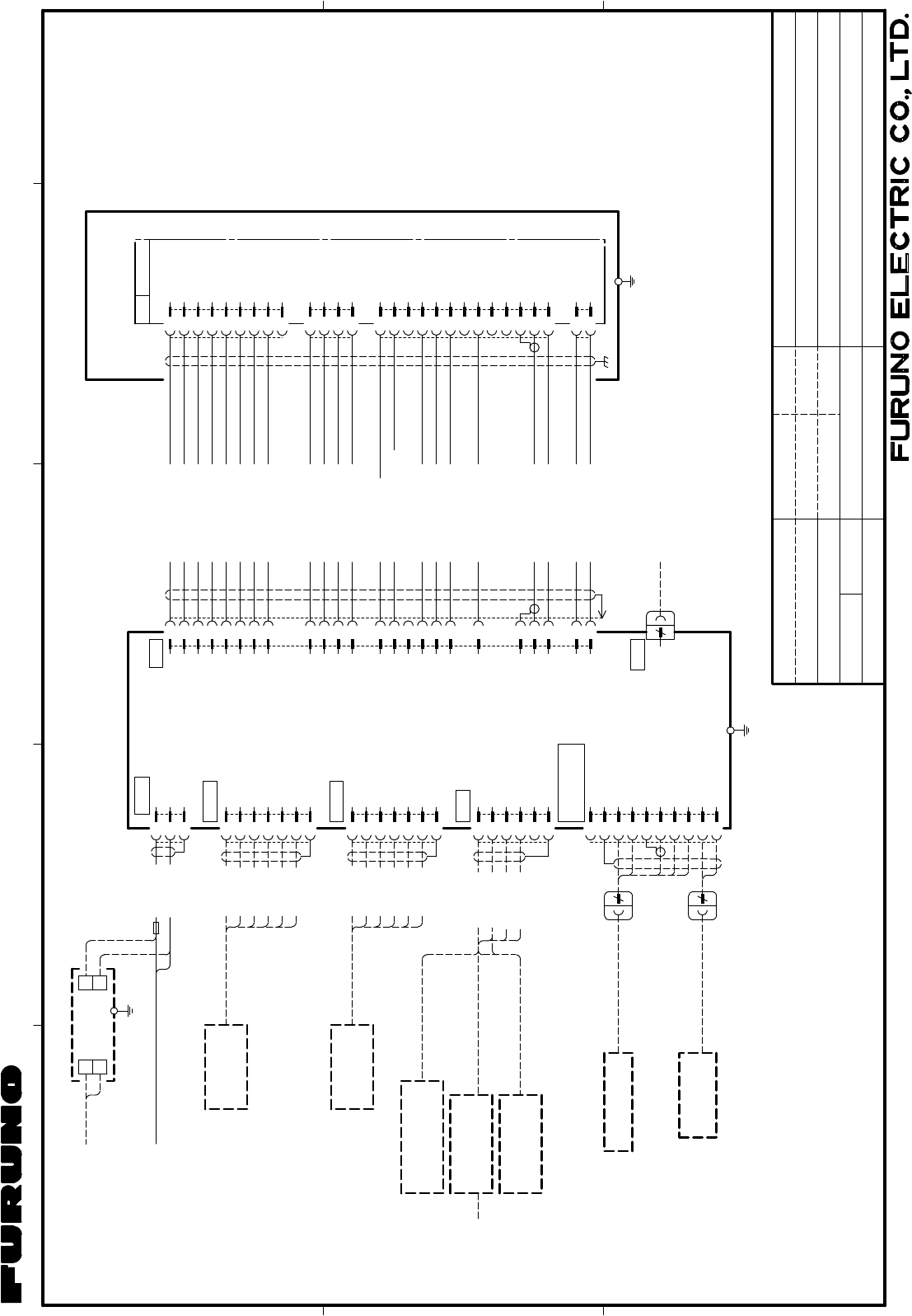
MARINE RADAR
INTERCONNECTION DIAGRAM
船舶用レーダー
相互結線図
T.YAMASAKI
DWG.No. REF.No.
H.MAKI
FR-8065/8125
*2: OPTION.
*1: SHIPYARD SUPPLY.
*3: GROUND SHIELD EFFECTIVELY AT BOTH ENDS.
NOTE
注記
*3) シールドは両端で完全にアースする。
*1) 造船所手配。
*2) オプション。
03-185-6003-0
1
2
3
4
5
6
NMEA1
MJ-A7SPF
7
GRN
YEL
WHT
キ
シロ
ミドリ
BLK
クロ
アカ RED
アオ BLU
航法装置
NAV EQUIPMENT
(NMEA0183) 5m,φ7
*2
1
2
3
4
5
6
MJ-A7SPF
7
GRN
YEL
WHT
キ
シロ
ミドリ
BLK
クロ
アカ RED
アオ BLU
航法装置
NAV EQUIPMENT
(NMEA0183) 5m,φ7
*2
HDG
キ
クロ
シロ
GRN
YEL
BLK
WHT
MJ-A6SPF
1
2
3
4
5
6
ミドリ
1
2
3
4
MJ-A7SPF0007-050C
MJ-A7SPF0007-050C
NMEA2
RD1-C
RD1-H
TD1-B
TD1-A
SHIELD
SHIELD
NC
TD2-A
TD2-B
RD2-H
RD2-C
ジャイロ A-D CONVERTER
A-Dコンバータ
AD-100
HEADING SENSOR
ヘディングセンサー
*2 MJ-A6SPF0003-050C/100C
5/10m,φ6
10m,φ6
MJ-A6SPF0007-100C
*2
サテライトコンパス
SATELLITE COMPASS
SC-50/100 *2 10m,φ6
MJ-A6SPF0007-100C
*2
*2
NC
SHIELD
OP_TRIG
OP_BP
5
6
EXT_BUZZ_12V
EXT_BUZZER
10 OP_VIDEO_GND
7
8
9
OP_VIDEO
OP_HD
GND
MJA7SPF0007-050C,5m
MJ-A10SPF
W0001+R
10
7
SHIELD
選択
SELECT
GYRO
*2PG-500/1000
GYRO_DATA-H
GYRO_DATA-C
GYRO_CLK-H
GYRO_CLK-C
NMEA1_12V
NMEA1_GND
NMEA2_12V
NMEA2_GND
MJ-B24LPF0010-**0+R
EXT. BUZZER
外部ブザー
*2
OP03-21
10
11
20
14
15
2
8
7
17
9
1
18
22
21
16
6
13
12
19
3
4
23
24
DJ-1
5
*3
4
TYPE A
USB
PC FOR MAINTENANCE
パソコン(保守用)
(21C+2C2V)
ミドリ
アオ
チャ
チャ(太)
シロ(太)
アカ(太)
クロ(太)
キ (太)
GRN
BLU
BRN
BRN(B)
WHT(B)
RED(B)
BLK(B)
YEL(B)
クロ
ムラサキ(太)
BLK
PPL(B)
シロ
アオ(太)
WHT
BLU(B)
ミドリ(太)
ダイ(太)ORG(B)
キ YEL
COAX.ドウジク
8
7
6
5
4
3
2
1
9
RTB 03P9405A
4
3
2
1
5
6
7
8
4
3
2
1
9
10
11
12
13
2
1
空中線部 ANTENNA UNIT
RSB-0070/0073
*3
-12V
GND
+12V
+12V
-12V
TX-TRIG.
NC
BP
HD.
J821(VH9P)
J823(VH4P)
NC
MBS-L
NC
GND
NC
NC
GND
VIDEO
J822(VH2P)
-12V
+12V
TUNE_CONT
MOTOR-H
MOTOR-H
MOTOR-C
MOTOR-C
MOTOR-H
PL-A
PL-B
J824(SH13P)
TUNE_IND
RW-4747,0.3m
L-GRN(B)キミドリ(太)
モモ(太)PNK(B)
アカ
ハイ(太)GRY(B)
RED
ダイ ORG
PPLムラサキ
MJ-B24LPF0012-**0+R,5/10/15/20/30m,φ11
IV-2sq.
*1
EXT-BUZZ/
SUB DISPLAY
10/20/30m,φ11
*2
副指示器
REMOTE DISPLAY
WHT
BLK
MJ-A3SPF
3
2
1
POWER
(-)
(+)
SHIELD DISPLAY UNIT
指示部
RDP-154
MJ-A3SPF0017-050ZC,5m,φ10
24 VDC
(-)
(+) 5
6
DPYC-1.5
*1
1φ,50/60Hz
100-115/
220-230VAC 1
2
整流器
RECTIFIER
IV-2sq.
*1
シロ
クロ
RU-3423
GRN(B)
*2
10A
(RTR-085A/086A)
C3632-C01- B
24/Jan/2014
24/Jan/2014
24/Jan/2014 H.MAKI
S-2
A
B
C
123 4
kg
名称
NAME
TITLE
MASS
SCALE
APPROVED
CHECKED
DRAWN
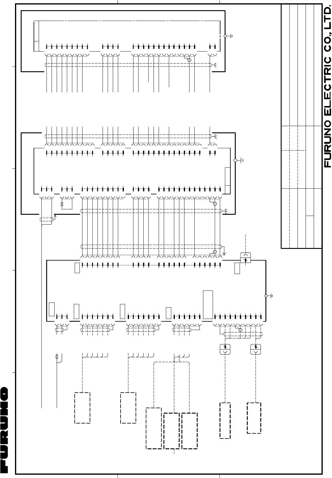
MARINE RADAR
INTERCONNECTION DIAGRAM
船舶用レーダー
相互結線図
T.YAMASAKI
DWG.No. REF.No.
H.MAKI
FR-8255
*2: OPTION.
*1: SHIPYARD SUPPLY.
*3: GROUND SHIELD EFFECTIVELY AT BOTH ENDS.
NOTE
注記
*1) 造船所手配。
*2) オプション。
*3) シールドは両端で完全にアースする。
3
2
1J1(VL3P)
(-)
(+)
空中線電源部
POWER SUPPLY UNIT
PSU-008
J2(VL3P)
1
2
3
J3(VH9P)
9
1
5
6
2
3
4
7
8
J4(VH4P)
4
3
2
1
J5(NH13P)
4
3
2
1
5
6
7
8
9
10
11
12
13
03P9419PWR
IV-2sq.
*1
10
11
20
14
15
2
8
7
DJ-1 5m,φ11
6
16
21
13
12
24
4
3
19
23
22
18
5
17
1
9
*3
4
TYPE A
USB
PC FOR MAINTENANCE
パソコン(保守用)
-12V
GND
+12V
+12V
-12V
NC
BP
NC
MBS-L
NC
GND
NC
NC
GND
VIDEO
*3
ミドリ
アオ
チャ
チャ(太)
シロ(太)
アカ(太)
クロ(太)
キ (太)
GRN
BLU
BRN
BRN(B)
WHT(B)
RED(B)
BLK(B)
YEL(B)
J13(VH5P)
J14(NH14P)
J11(VH2P)
J12(VH10P)
14
13
12
11
10
9
8
7
6
5
4
3
2
1
5
4
3
2
1
10
9
8
7
6
5
4
3
2
1
2
1
クロ
ムラサキ(太)
BLK
PPL(B)
シロ
アオ(太)
WHT
BLU(B)
ダイ(太)ORG(B)
アカ RED
キ YEL
ミドリ(太)
モモ(太)PNK(B)
WHT/RED(B)シロ/アカ(太)
シロ/ダイ WHT/ORG
ドウジク COAX.
シロ/チャ WHT/PPL
(17C+2C2V,MAX.30m)
8
7
6
5
4
3
2
1
9
RTB
-12V
GND
+12V
+12V
-12V
TX-TRIG.
NC
J821(VH9P)
空中線部
4
3
2
1BP
J823(VH4P)
5
6
7
8
4
3
2
1
9
10
11
12
13
*3
NC
MBS-L
NC
GND
NC
NC
GND
VIDEO
RW-9771,10/15/20/30m,φ14.5
ANTENNA UNIT
*3
VL3P-VV-S2X2C-AA050,5m,φ10
IV-2sq.
*1
シロ
クロ
WHT
BLK
MJ-A3SPF
3
2
1
POWER
GND
(-)
(+)
RDP-154
DISPLAY UNIT
指示部
1
2
3
4
5
6
NMEA1
MJ-A7SPF
7
GRN
YEL
WHT
キ
シロ
ミドリ
BLK
クロ
アカ RED
アオ BLU
航法装置
NAV EQUIPMENT
(NMEA0183) 5m,φ7
*2
1
2
3
4
5
6
MJ-A7SPF
7
GRN
YEL
WHT
キ
シロ
ミドリ
BLK
クロ
アカ RED
アオ BLU
航法装置
NAV EQUIPMENT
(NMEA0183) 5m,φ7
*2
HDG
MJ-A6SPF
1
2
3
4
5
6
MJ-A7SPF0007-050C
MJ-A7SPF0007-050C
NMEA2
RD1-C
RD1-H
TD1-B
TD1-A
SHIELD
SHIELD
TD2-A
TD2-B
RD2-H
RD2-C
NMEA1_12V
NMEA1_GND
NMEA2_12V
NMEA2_GND
NC
SHIELD
GYRO_DATA-H
GYRO_DATA-C
GYRO_CLK-H
GYRO_CLK-C
キ
クロ
シロ
GRN
YEL
BLK
WHT
ミドリ
A-D CONVERTER
A-Dコンバータ
AD-100
HEADING SENSOR
ヘディングセンサー
*2 MJ-A6SPF0003-050C/100C
5/10m,φ6
10m,φ6
MJ-A6SPF0007-100C
*2
サテライトコンパス
SATELLITE COMPASS
SC-50/100 *2 10m,φ6
MJ-A6SPF0007-100C
*2
*2
*2PG-500/1000
ジャイロ
選択
SELECT
GYRO
5m,φ10
MJ-A3SPF0017-050ZC,
24 VDC
1
2
3
4
NC
SHIELD
OP_TRIG
OP_BP
5
6
EXT_BUZZ_12V
EXT_BUZZER
10 OP_VIDEO_GND
7
8
9
OP_VIDEO
OP_HD
GND
MJA7SPF0007-050C,5m
MJ-A10SPF
W0001+R
10
7
MJ-B24LPF0010-**0+R
EXT. BUZZER
外部ブザー
*2
OP03-21
7A
TX_TRIG
PL-A
PL-B
MOTOR-H
HD
MOTOR-C
TUNE_IND
MOTOR-C
MOTOR-H
MOTOR-H
TUNE_CONT
03P9405
PL-A
PL-B
MOTOR-H
HD
MOTOR-C
TUNE_IND
MOTOR-C
MOTOR-H
MOTOR-H
TUNE_CONT
RW-4747
2
1
J822(VH2P)
TX-HV
NC
MJ-B24LPF0011-050+R
03-185-6004-0
J824(SH13P)
EXT-BUZZ/
SUB DISPLAY
10/20/30m,φ11
*2
副指示器
REMOTE DISPLAY
24 VDC
GRN(B)
10A
RSB-0070/0073(RTR-087A)
C3634-C01- B
24/Jan/2014
24/Jan/2014
24/Jan/2014 H.MAKI
S-3

The paper used in this manual
is elemental chlorine free.
・FURUNO Authorized Distributor/Dealer
9-52 Ashihara-cho,
Nishinomiya, 662-8580, JAPAN
A
:
JAN
2014
.
Printed in Japan
All rights reserved.
A1
:
FEB
.
07, 2014
Pub. No.
IME-36320-A1
(
GREG
)
FR-8045/8065/8125
0 0 0 1 7 8 5 0 7 1 0