Furuno USA 9ZWRTR088B Transceiver for Radar model FR-8045 User Manual
Furuno USA Inc Transceiver for Radar model FR-8045
Contents
User Manual I Part 1

www.furuno.com
All brand and product names are trademarks, registered trademarks or service marks of their respective holders.
Installation Manual
MULTI-COLOR LCD RADAR
Model FR-8045/FR-8065/FR-8125/FR8255
SAFETY INSTRUCTIONS ................................................................................................ i
SYSTEM CONFIGURATION ........................................................................................... ii
EQUIPMENT LISTS........................................................................................................ iii
1. HOW TO INSTALL THE SYSTEM ............................................................................. 1
1.1 Display Unit...........................................................................................................................1
1.2 Antenna Unit Installation.......................................................................................................5
1.3 Power Supply Unit ..............................................................................................................19
2. CABLE CONNECTION
AND WIRING20
2.1 Standard Connection ..........................................................................................................20
2.2 Wiring the Power Supply Unit (FR-8255 only) ....................................................................21
2.3 Data Signals........................................................................................................................23
2.4 Input/Output Ports...............................................................................................................23
3. EQUIPMENT SETTINGS.......................................................................................... 25
3.1 Setting the Language..........................................................................................................25
3.2 How to Set the Purpose ......................................................................................................26
3.3 How to Enter Initial Settings................................................................................................27
4. OPTIONAL EQUIPMENT ......................................................................................... 31
4.1 ARP Kit ARP-11..................................................................................................................31
4.2 Connection of Buzzer and/or Remote Display....................................................................33
PACKING LISTS ......................................................................................................... A-1
OUTLINE DRAWINGS ................................................................................................ D-1
INTERCONNECTION DIAGRAMS.............................................................................. S-1
i
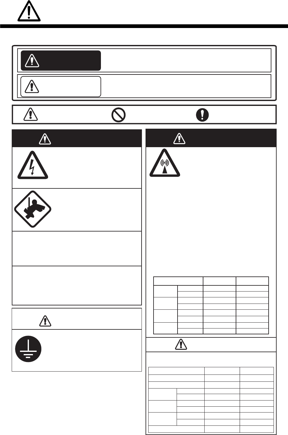
SAFETY INSTRUCTIONS
WARNING
Radio Frequency
Radiation Hazard
WARNING
CAUTION
CAUTION
CAUTION
CAUTION
WARNING
Indicates a condition that can cause death or serious
injury if not avoided.
CAUTION
Indicates a condition that can cause minor or moderate
injury if not avoided.
Warning, Caution Mandatory Action
Prohibitive Action
Read these safety instructions before you operate the equipment.
Do not open the equipment unless
totally familiar with electrical
circuits and service manual.
Only qualified personnel should work
inside the equipment.
Wear a safety belt and hard hat
when working on the antenna unit.
Serious injury or death can result if
someone falls from the radar mast.
Construct a suitable service platform from
which to install the antenna unit.
Serious injury or death can result if someone falls
from the radar mast.
Turn off the power at the mains switchboard
before beginning the installation.
Fire, electrical shock or serious injury can result if
the power is left on or is applied while the
equipment is being installed.
Ground the equipment to prevent
electrical shock and mutual
interference. Observe the following compass safe distances
to prevent deviation of a magnetic compass.
The radar antenna emits electromagnetic radio
frequency (RF) energy which can be harmful,
particularly to your eyes. Never look directly into
the antenna aperture from a close distance while
the radar is in operation or expose yourself to
the transmitting antenna at a close distance.
Distances at which RF radiation levels of 100 W/m
2
and 10 W/m
2
exist are given in the table below.
Note: If the antenna unit is installed at a close
distance in front of the wheel house, your
administration may require halt of transmission
within a certain sector of antenna revolution. This is
possible - Ask your FURUNO representative or
dealer to provide this feature.
FR-8065
100W/m
2
10W/m
2
FR-8125
FR-8255
FR-8045
Model
Display Unit RDP-154
FR-8065
Antenna
FR-8125
Antenna
FR-8255
Antenna
FR-8045 Antenna
1.00m
1.95m
0.65m
1.25m
PSU-008
0.80m 0.50m
RSB-0070
RSB-0070
RSB-0070
RSB-0073
RSB-0073
RSB-0073
1.90m
1.00m
1.10m
1.85m
1.80m
0.95m
1.20m
0.60m
0.70m
1.25m
1.15m
0.60m
Model Standard Steering
XN-12A
XN-13A
XN-12A
XN-13A
XN-12A
XN-13A
XN-12A
XN-13A N/A
N/A
N/A
N/A
N/A
N/A
1.1m
1.0m
1.9m
0.6m
0.4m 3.1m
4.6m
1.7m
2.1m
1.9m
ii
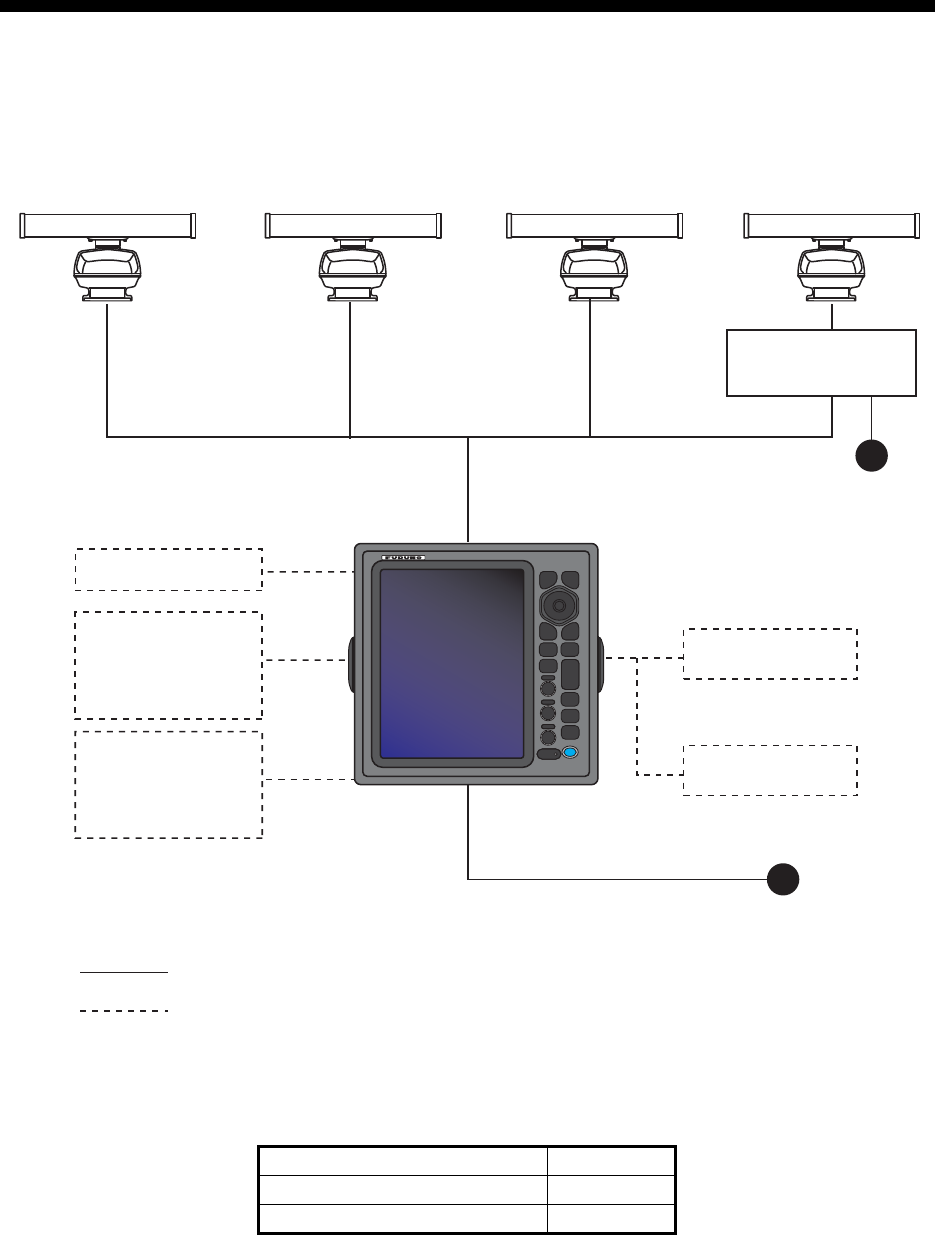
SYSTEM CONFIGURATION
Note 1: 12 VDC cannot be used with this equipment.
Note 2: When replacing the antenna, make sure the correct SPU board is used, referring to the
table below.
Model SPU Board
FR-8045 03P9586B
FR-8065/FR-8125/FR-8255 03P9586A
24 VDC
Display unit
RDP-154
External buzzer
Echo sounder
GPS navigator
AIS, etc.
Remote display
: Basic configuration
Heading sensor
Echo sounder
GPS navigator
AIS, etc.
: Optional
Model FR-8065
Antenna Unit
XN-12A-RSB-0070-085A
XN-12A-RSB-0073-085A
XN-13A-RSB-0070-085A
XN-13A-RSB-0073-085A
Model FR-8125
Antenna Unit
XN-12A-RSB-0070-086A
XN-12A-RSB-0073-086A
XN-13A-RSB-0070-086A
XN-13A-RSB-0073-086A
Model FR-8255
Antenna Unit
XN-12A-RSB-0070-087A
XN-12A-RSB-0073-087A
XN-13A-RSB-0070-087A
XN-13A-RSB-0073-087A
24 VDC
Antenna Power Supply
PSU-008
Model FR-8045
Antenna Unit
XN-12A-RSB-0073-088B
XN-13A-RSB-0073-088B

iii
EQUIPMENT LISTS
Standard Supply
Name Type Code No. Qty Comments
Display Unit RDP-154 — 1
Antenna Unit
RSB-0070/0073-085A —
1 Radiator: XN-12A or XN-13A
RSB-0070/0073-086A —
RSB-0070/0073-087A —
RSB-0073-088B —
Power Unit PSU-008 — 1 5m Cable For FR-8255
Installation
Materials
CP03-30700 000-090-471
1
10m Cable
For FR-8065/
or FR-8125
CP03-30710 000-090-472 15m Cable
CP03-30720 000-090-473 20m Cable
CP03-30730 000-090-474 30m Cable
CP03-30500 000-083-620
1
10m Cable
For FR-8255
CP03-30510 000-083-621 15m Cable
CP03-30520 000-083-622 20m Cable
CP03-30530 000-083-623 30m Cable
CP03-35600 000-024-717 1 For Display Unit
(Screws, Code: 000-162-608-10,
5×20 SUS304)
CP03-33000 000-014-604
1
5m Cable
For FR-8045
CP03-33010 000-014-605 10m Cable
CP03-33020 000-014-606 15m Cable
CP03-33030 000-014-607 20m Cable
CP03-33040 000-014-608 30m Cable
CP03-33801 001-141-670 1 For Antenna Unit:
FR-8065/FR-8125/FR-8255
CP03-18401 008-503-360 1 For Antenna Unit: FR-8045
CP03-22901 008-219-760 1 For Radiator
CP03-30600 000-084-769 1 For PSU-008
Spare Parts SP03-17701 001-258-000 1 For Display Unit: Fuse
(Code: 000-155-826-10,
FGBO 125V 10A PBF)
SP03-14501 008-444-420 1 For PSU-008
Accessories FP03-12301 001-258-020 1 LCD Cleaning Cloth
(Code: 100-360-672-10,
19-028-3125-2)

EQUIPMENT LISTS
iv
Optional supply
Name Type Code No. Qty Comments
Auto Plotter ARP-11 008-523-050 1
External Alarm
Buzzer
OP03-21 000-030-097 1
Signal Cable
Assembly
MJ-B24LPF0010-100+R 000-147-880-12
1 For Remote Display UnitMJ-B24LPF0010-200+R 000-147-881-12
MJ-B24LPF0010-300+R 000-147-882-12
MJ-A7SPF0007-050C 000-154-028-10 1 For NMEA1/2
MJ-A6SPF0007-100C 000-159-695-10 1 For Heading Sensor
MJ-A10SPFW0001+R 001-074-600-10 1 For Remote Display Unit/
External Display splitter
cable
Flush Mount Kit OP03-228 001-258-030 1

1
1. HOW TO INSTALL THE SYSTEM
1.1 Display Unit
Select a location for the display unit by following the information shown below.
• The unit is waterproof, but FURUNO recommends that you install the display unit in
a cabinet.
• Keep the unit away from direct sunlight.
• The temperature and humidity must meet the requirements shown in the equipment
specifications.
• Set the unit away from the exhaust pipes and vents.
• The installation location must have enough cool air.
• Install the unit where shock and vibration meet the requirements shown in the
equipment specifications. If there is heavy vibration, vertically install the display unit
on the hanger.
• Keep the unit away from equipment that creates an electromagnetic field, for exam-
ple, motors and generators.
• For maintenance and checking, leave enough space at the sides and rear of the
unit, referring to the outline drawing and provide some additional length in cables.
• Follow the recommended compass safe distances shown on page i to prevent the
interference to a magnetic compass.
NOTICE
Do not apply paint, anti-corrosive sealant or
contact spray to plastic parts or equipment
coating.
These items contain products that can
damage plastic parts and equipment coating.
1. HOW TO INSTALL THE SYSTEM
2
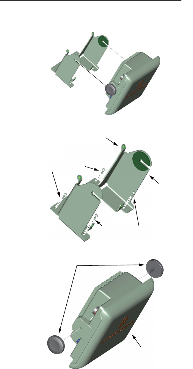
1.1.1 How to install the display unit
How to install the display unit on a desktop or overhead
Follow the procedure shown below to install the display unit on a desktop or overhead.
1. Unfasten the knob bolts and remove the display unit from the hanger.
2. Fasten the hanger with four self-tapping screws.
3. Screw the knob bolts into the display unit, leaving them slightly loose.
4. Connect all necessary cabling.
5. Set the display unit in the hanger, then fasten the knob bolts.
Note: For overhead installation, make sure the location is strong enough to hold the
unit. If necessary, fasten the hanger with the bolts, nuts and washers (local supply).
ø5×20 Self-tapping screws
ø5×20 Self-tapping screws
Hanger rear
Hanger front
Knobs
Hard cover
1. HOW TO INSTALL THE SYSTEM
3
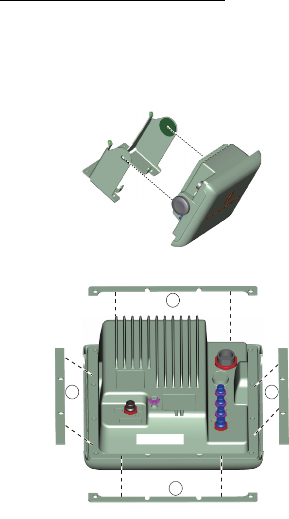
How to install the display unit in a console
Note: The unit must be installed in a flat area of the console. Ensure there is ample
room behind the unit once installed to allow access for maintenance.
Follow the procedure shown below to install the display unit in a console.
1. Prepare a hole in the installation location referring to the outline drawing at the
back of this manual.
2. Unfasten the knob bolts and remove the display unit from the hanger.
3. Fit the backing sponges, referring to the diagram below.
Note 1: Ensure the backing sponges are used correctly. 1 - Horizontal, 2 - Verti-
cal.
Note 2: Take care to place the backing sponges around screw holes and ensure
there are no gaps between the sponges at their joining points.
4. Connect all necessary cables to the unit, making sure to leave enough slack for
maintenance and service.
5. Insert the unit into the console, making sure that all cabling attached to the unit is
not damaged. Ensure the unit is secure before proceeding to the next step.
Top
Bottom
Unit base
1
1
2 2
1. HOW TO INSTALL THE SYSTEM
4
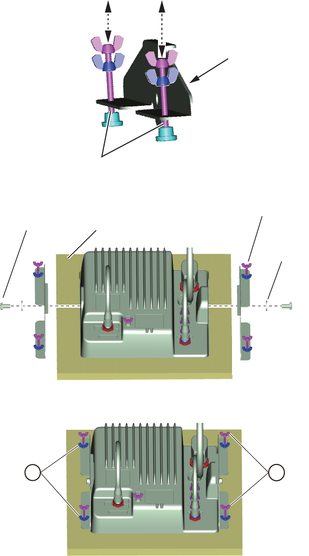
6. Adjust the flush-mounting fixture by loosening the wingnuts and wingscrews to al-
low the bolt free movement. Use the figure below for reference.
7. Attach the flush-mounting fixture to the unit referring to the diagram below.
8. Fasten the four wingscrews until the footing is flush against the mounting area.
See No. 2 in the figure below for reference.
9. Tighten the four wingnuts until the unit is firmly secured. See No. 1 in the figure
above for reference.
Minimal distance between protector and clamp.
Flush-mounting fixture
Console
Flush-mounting fixture
Washer
M8×15 Bolt
2
1
1. HOW TO INSTALL THE SYSTEM
5
1.2 Antenna Unit Installation
How to select the location for the antenna unit
• The antenna unit is installed either on top of the wheelhouse or a platform on the
radar mast. Install the antenna unit where there is a good complete view. Any ob-
struction causes blind sectors. For example, a mast with a diameter smaller than
the horizontal beamwidth of the radiator causes only a small blind sector. A horizon-
tal spreader or crosstrees in the same horizontal plane creates a large obstruction.
Install the antenna unit above, or below a horizontal spreader or crosstrees.
• You cannot put the antenna unit where there is a completely clear view in all direc-
tions. Make sure you check for blind sectors on the radar screen after you have in-
stalled the radar.
• To reduce the electrical interference, do not run the signal cable near other electri-
cal equipment. Also do not run the cable in parallel to power cables.
• A magnetic compass gives error if the antenna unit is installed near the magnetic
compass. See SAFETY INSTRUCTIONS for the compass safe distances to prevent
the interference to a magnetic compass.
• Do not apply paint to the radiator aperture. The radar wave cannot be transmitted if
there is paint on the radiator.
• If this radar is installed on a large vessel, follow the points shown below:
• The length of the signal cable between the antenna unit and the display unit is
max. 30 m.
• The output from a funnel or exhaust vent decreases aerial performance and hot
gases can damage the radiator. The antenna unit must not be installed where the
temperature is more than 55°C.
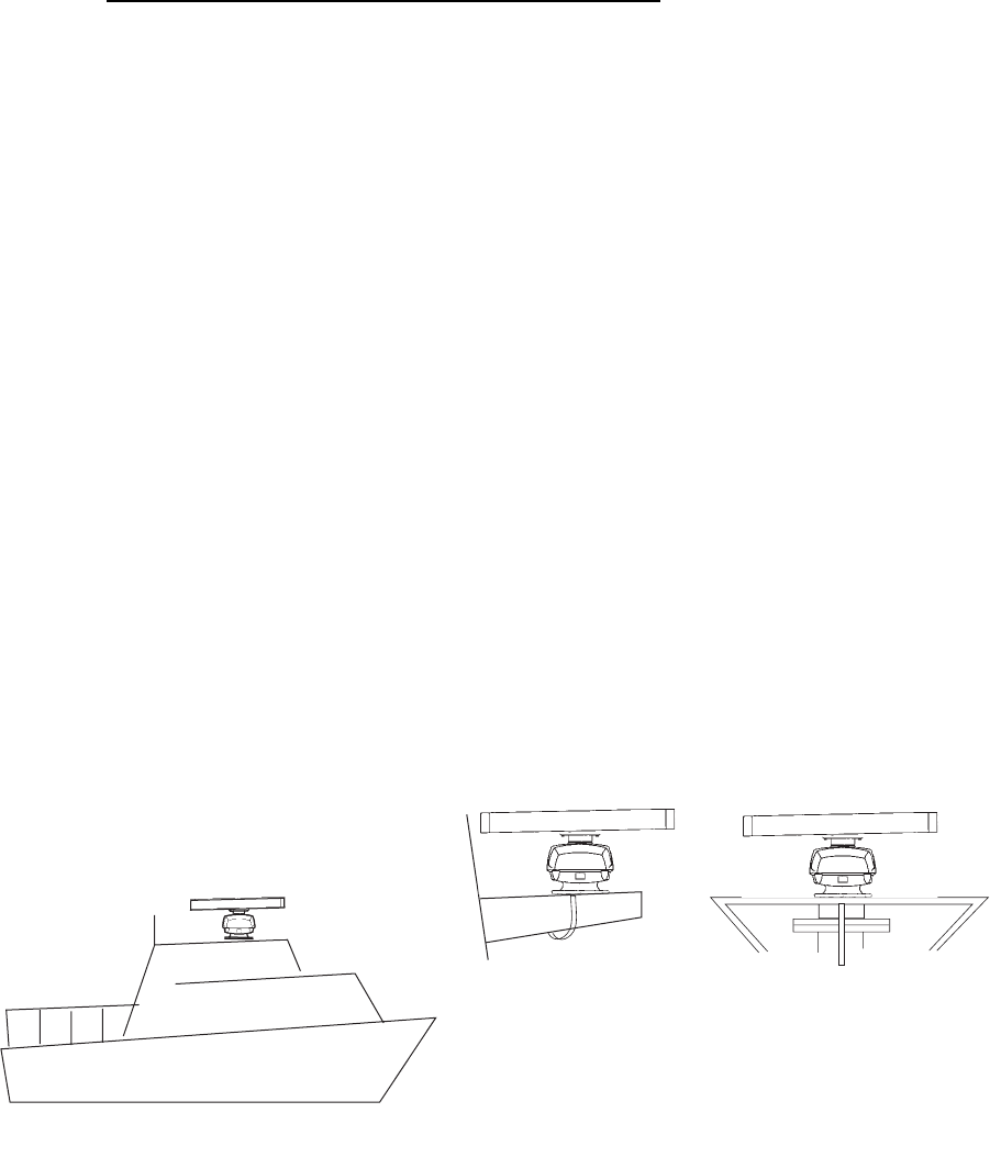
• The antenna unit can be installed on the bridge, a common mast, or the radar mast.
(a) On bridge
(c) Radar mast
(b) Common mast
1. HOW TO INSTALL THE SYSTEM
6
1.2.1 Installation procedure
Refer to the outline drawing at the back of this manual for the dimensions. Make five
holes in the platform. Four holes to fasten the antenna unit and one hole for the signal
cable.
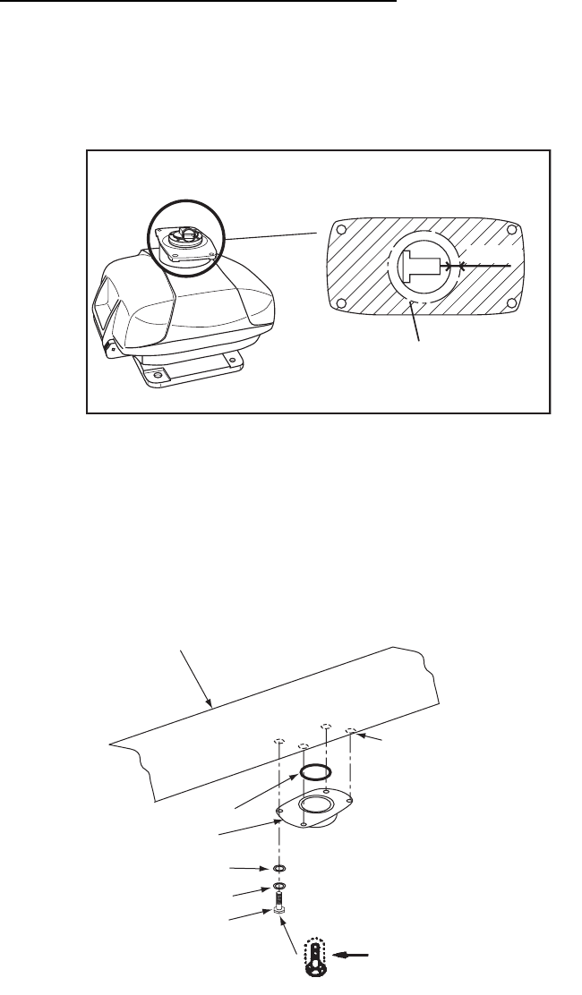
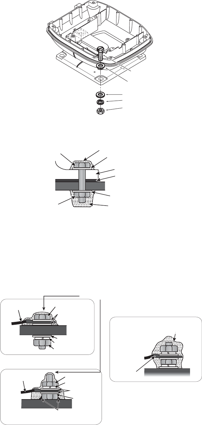
How to fasten the radiator to the chassis
See the packing list at the back of this manual for the installation materials.
1. Remove the radiator cap from the radiator bracket.
2. Apply marine sealant to the surface of the antenna radiator and the radiator brack-
et. See the figure shown below for the location.
3. Apply the marine sealant to the threads in the four holes on the antenna radiator.
4. Apply the grease to the O-ring and set the O-ring to the radiator bracket.
5. Set the antenna radiator on the radiator bracket.
6. Apply the marine sealant to the radiator bolts (4 pieces). Fasten the antenna radi-
ator to the radiator bracket with the radiator bolts, flat washers and spring wash-
ers.
RADIATOR BRACKET
(top view)
Coat hatched area with
marine sealant.
10mm
Flat washer
Spring washer
Hex head bolt
(M8×30)
Radiator bracket
Apply marine sealant
to bolts.
Antenna
radiator
O-ring
Apply marine sealant
to threaded holes
1. HOW TO INSTALL THE SYSTEM
7
1.2.2 How to install the antenna unit
You can install the antenna unit by one of the two methods shown below.
• Use the outside holes
• Use the inside holes
How to use outside holes of the antenna housing
Use the hex head bolts (supplied) to install the antenna unit as shown in the illustration
below.
1. Put the rubber mat (supplied) on the platform.
2. Put the antenna unit on the rubber mat. Align the position of the antenna unit as
shown in the illustration below.
Ground
terminal
Rubber
mat
Bow mark
Stern
Bow
CAUTION
CAUTION
Do not lift the antenna by the radiator,
the radiator may be damaged.
Always lift the antenna by the housing.
1. HOW TO INSTALL THE SYSTEM
8
3. Set four hex head bolts (M12×60, supplied) and seal washers (supplied) from the
top of the antenna housing, as shown below.
4. Set the flat washers (M12, supplied), spring washers (supplied) and nuts (sup-
plied) to the hex head bolts. Tighten by turning the nuts. Do not tighten by turning
the hex head bolts, to prevent damage to the seal washers.
5. Apply anti-corrosive sealant to the flat washers, spring washers, nuts and visible
parts of bolts.
6. Prepare the ground point on the platform. Use an M6×25 bolt, nut and flat washer
(supplied). The ground point must be within 300 mm from the ground terminal on
the antenna unit.
7. Run the ground wire (RW-4747, 340 mm, supplied) between the ground terminal
and the ground point.
8. Apply marine sealant to the ground terminal and ground point as shown below.
Hex bolt
Seal washe
r
Flat washer
Spring washer
Nut
Seal washer
Antenna chassis
Corrosion proof
rubber mat
Seal washer
Marine sealant
Marine sealant
Bolt
Nut
OR
Coat with marine sealant.
Hex bolt
Ground wire
Flat washer
Hex nut
Spring washer
Flat washer
Mounting Platform
Mounting Platform
Hex nut
Hex bolt
Flat washer
Spring washer
Ground wire
Mounting Platform
Mounting Platform
Welding
Ground wire
Antenna chassis
Antenna chassis
Fasten ground wire then
coat with marine sealant.
1. HOW TO INSTALL THE SYSTEM
9
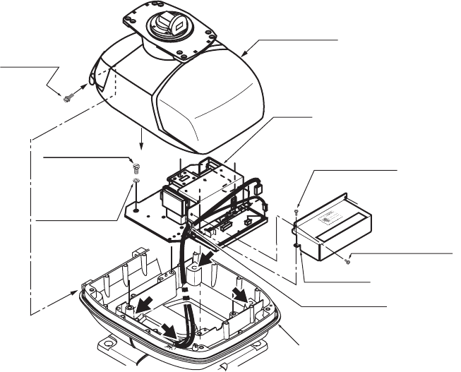
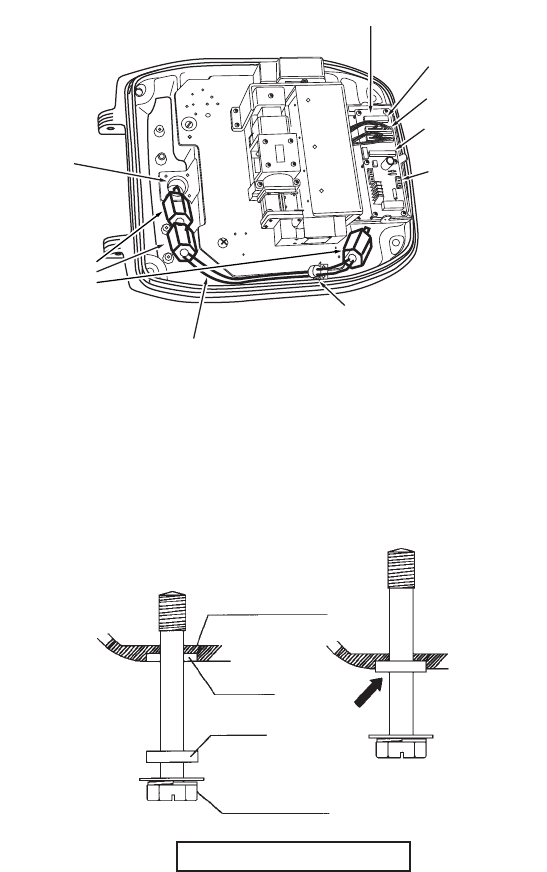
1.2.3 How to use the inside holes of the antenna housing (FR-8045)
This method requires removal of the RF unit from the antenna unit to access the inside
fixing holes. Use four hex head bolts, flat washers, spring washers and nuts (local sup-
ply) to install the antenna unit. Check the length of the bolts before you install.
Antenna unit chassis, upper chassis separated
1. Unfasten four bolts on the cover to open the antenna unit.
2. Disconnect the connectors connected between the upper chassis and the lower
chassis.
3. Remove two hex head bolts (M8×25) to separate the upper chassis from the lower
chassis.
4. Loosen four pan head screws to remove the cover from the pc board.
5. Remove the connector from the RF unit.
6. Loosen four hex head bolts to remove the RF unit.
7. Set the corrosion-proof rubber mat (supplied) to the support platform.
8. Cut the rubber bushings in the fixing holes and put four bolts from the inside of the
lower chassis. Fasten the lower chassis to the support platform with the spring
washers, flat washers and nuts (local supply). Apply marine sealant to the flat
washers, nuts and visible parts of bolts.
9. Assemble the RF unit, cover and chassis.
10. Set four caps (supplied) into the outside fixing holes.
11. Prepare the ground point on the platform. Use an M6×25 bolt, nut and flat washer
(supplied). The ground point must be within 300 mm from the ground terminal on
the antenna unit.
12. Run the ground wire (RW-4747, 340 mm, supplied) between the ground terminal
and the ground point.
13. Apply the marine sealant to the ground terminal and ground point. See the illus-
tration on page 8 for instructions.
RF unit
Hex head bolt
M10×20, 4 pcs.
Hex head bolt
M8×25,
2 pcs.
Spring Washer
M10, 4 pcs.
Board cover
Pan head screw
M3×8, 2 pcs.
Upper chassis
Square bushing
Lower chassis
Pan head screw
M3×8, 2 pcs.
1. HOW TO INSTALL THE SYSTEM
10
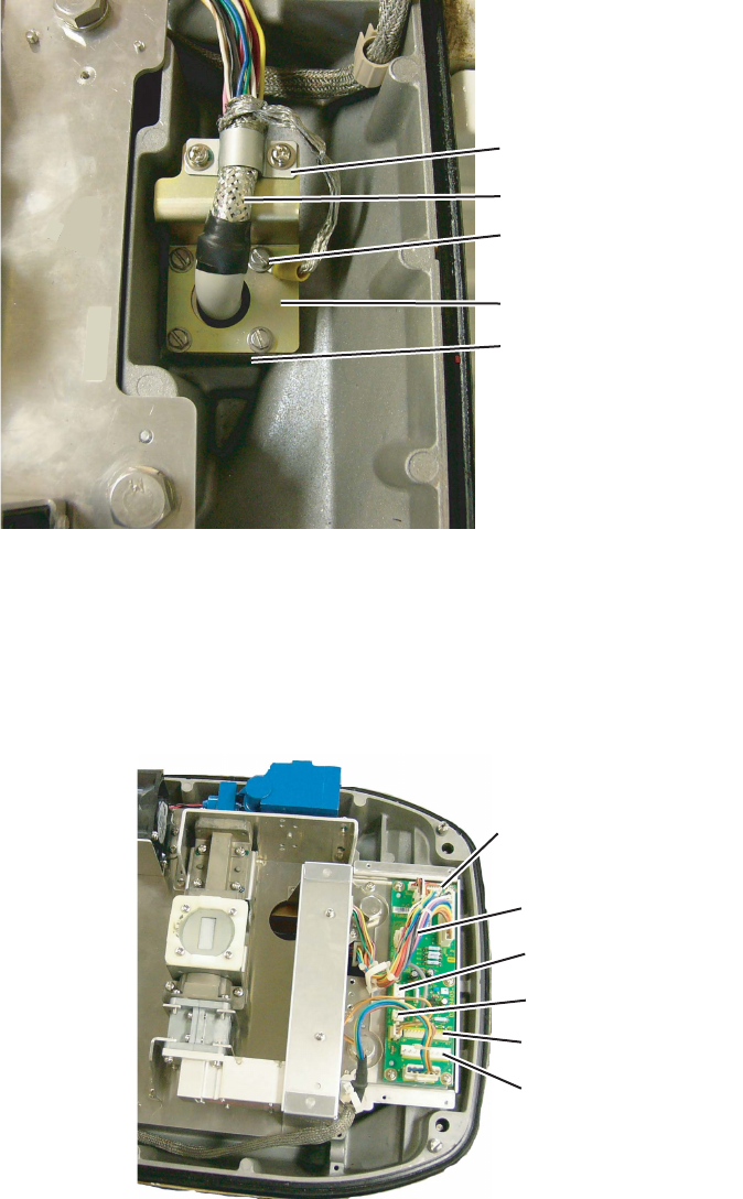
1.2.4 How to connect the signal cable (FR-8045)
The signal cable runs from the display unit to the antenna unit. To reduce the electrical
interference, do not run the signal cable near other electrical equipment. Also do not
run the cable in parallel to power cables. Put the cable through the hole and apply
sealing compound around the hole for waterproofing.
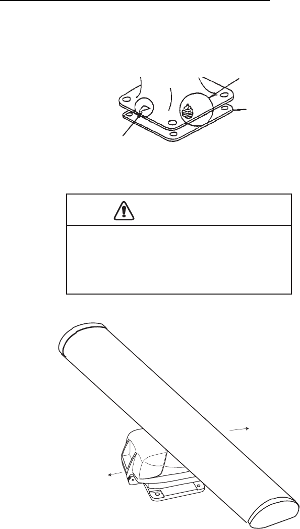
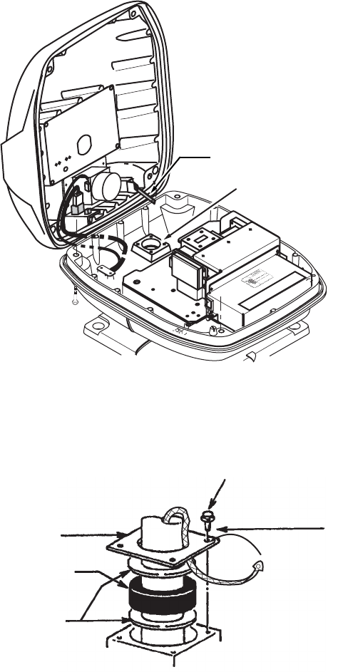
1. Loosen four bolts, open the antenna cover, and set the stay.
2. Loosen the cable gland assembly (plate, gasket, flat washer).
3. Put the signal cable with the connector through the bottom of the antenna unit
chassis. Put the cable through the gland assembly as shown below.
4. Fasten the crimp-on lug of the shield wire to one of the four fixing bolts of the cable
gland assembly.
Stay
Cable gland assy.
Bolt
Plate
Bolt
4 - M4×16
Gasket
Flat
washer
Shield wire
1. HOW TO INSTALL THE SYSTEM
11
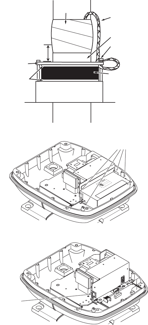
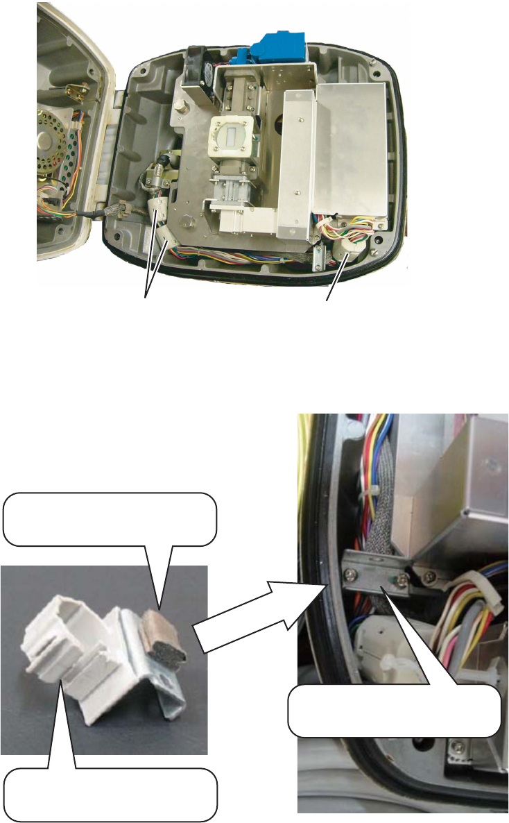
5. Put the signal cable so that no more than 4 cm of the sheath is visible, as shown
in the figure below. Tighten the fixing bolts.
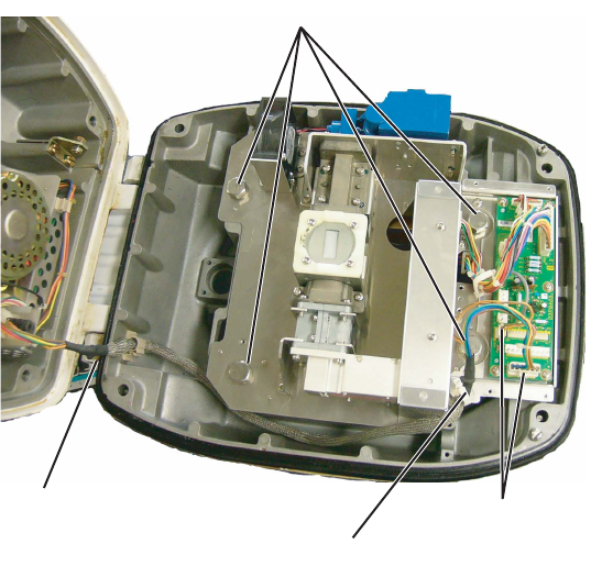
6. Loosen four screws in the figure shown below and open the cover.
7. Put the signal cable through the cable protector.
8. Connect the signal cable to the RTB Board (03P9249). See the interconnection
diagram and the figure shown on page 12.
Sheath
CABLE GLAND
Plate
Gasket
Flat
washer
Bolt
Within 4 cm
Taping
Shield wire
Four screws
Cable
protector
1. HOW TO INSTALL THE SYSTEM
12
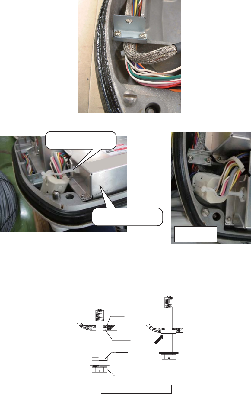
9. Attach three EMI cores to the signal cable as shown below.
10. Fasten the signal cable with the cable clamp.
11. Undo the stay and close the cover. Securely fasten the scanner bolts.
Note: When you close the cover, set the gaskets to the grooves in the bottom chassis,
then tighten the bolts.
Run cable along here.
Lead in
cable here.
J821 VH9P
RTB Board
J824 NH13P
J823 VH4P
Clamp
J822 VH2P
EMI core
RFC-13
Bottom
Chassis
Gasket
Groove
Antenna Bolt
Torque : 9.8 ±0.1 Nm
1. HOW TO INSTALL THE SYSTEM
13
1.2.5 How to use the inside holes of the antenna housing
(FR-8065/FR-8125/FR-8255)
This method requires removal of the RF unit in the antenna unit to access inside fixing
holes. Use hex head bolts, flat washers, spring washers and nuts (local supply) to
mount the antenna unit, confirming length of bolts.
1. Unfasten four antenna bolts on the cover to open the antenna unit.
2. Unfasten four screws on the RTB cover to remove it.
3. Unplug connector J827 and J834 on the RTB board
4. Separate upper chassis from lower chassis by removing two hex head bolts
(M8x25).
5. Remove RF unit by unfastening four hex head bolts.
Antenna unit, opened
6. Lay the corrosion-proof rubber mat (supplied) on the mounting platform.
7. Fasten the lower chassis to the mounting platform with hex head bolts, spring
washers, flat washers and nuts (local supply), and then coat flat washers, nuts
and exposed parts of bolts with marine sealant. Cut a slit in the rubber bushing
and insert bolt into the bushing. Do not use seal washers.
8. Reassemble RF unit, cover and chassis.
9. Set four knob caps (supplied) into outside fixing holes.
10. Do steps 6-8 in “Outside fixing holes” on page 8.
Hex. bolt(M10X20)
Hex. bolt(M8X25) J827, J834
Remove from cable clamp
1. HOW TO INSTALL THE SYSTEM
14
1.2.6 How to connect the signal cable (FR-8065/FR-8125/FR-8255)
Only the signal cable runs from the display unit (power supply unit in case of FR-8255)
to the antenna unit. In order to minimize the chance of picking up electrical interfer-
ence, avoid where possible routing the signal cable near other onboard electrical
equipment. Also, avoid running the cable in parallel with power cables. Pass the cable
through the hole and apply sealing compound around the hole for waterproofing.
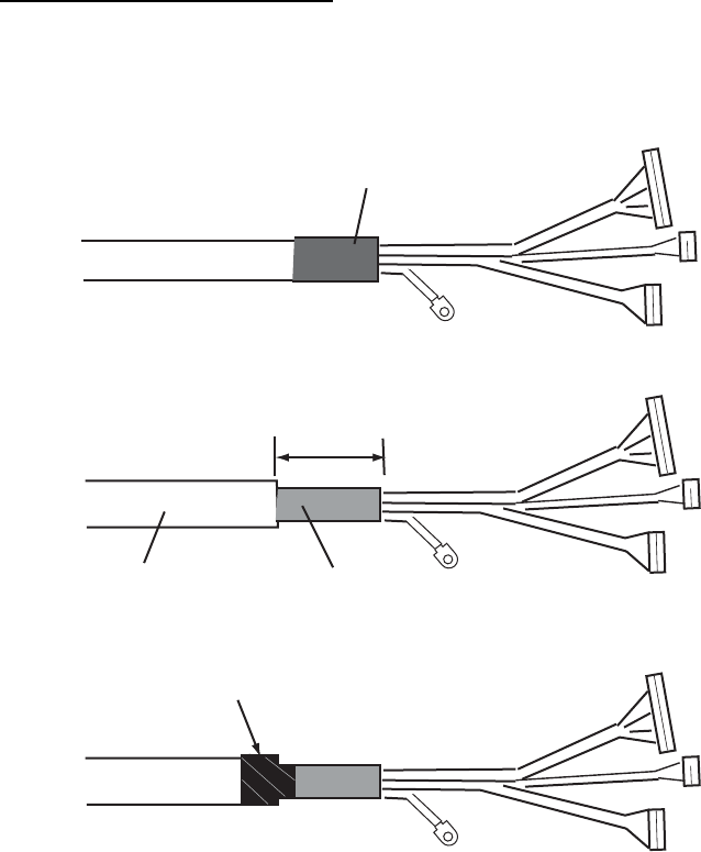
Fabricating the signal cable
This type of signal cable is used with other models of radar. For these models, the fol-
lowing fabrication is required.
1. Remove shrink tubing from the signal cable.
2. Remove vinyl sheath approx. 50 mm.
3. Wrap vinyl tape at the end of the vinyl sheath.
Remove shrink tubing.
Cut vinyl sheath approx. 50 mm.
Braided shield
Vinyl sheath
Vinyl tape
1. HOW TO INSTALL THE SYSTEM
15
Connecting the signal cable
1. Open the antenna cover by loosening four bolts, and then fix the stay.
Antenna unit chassis, cover opened
2. Unfasten the cable gland assembly (plate, gasket, flat washer). The plate may be
discarded.
3. Pass the signal cable with connector through the bottom of the antenna unit chas-
sis. Pass the cable through the gland assembly as shown below.
Passing the signal cable through the cable gland assembly
4. Fasten the gasket support with four bolts. Using one of the four bolts, fasten the
crimp-on lug to the shield wire.
Cable entry
RTB board cove
r
Gasket support
Gasket
Flat washer
Cable entry
1. HOW TO INSTALL THE SYSTEM
16
5. Fasten the shielded part of the signal cable with shield clamp (installation materi-
al) as shown below.
How to fix signal cable in cable gland
6. Unfasten four screws to remove the RTB board cover.
7. Connect the plugs of the signal cable to the RTB board.
Connecting to the RTB board
8. Reattach the RTB board cover.
FR-8065, FR8125 : J821, J823, J824, J822
FR-8255 : J821, J823, J824, J820
Shield clamp
Signal cable
Fix shield wire with bolt.
Gasket support
Cable Entry
RTB board
J820
J823
J822
J824
J821
1. HOW TO INSTALL THE SYSTEM
17
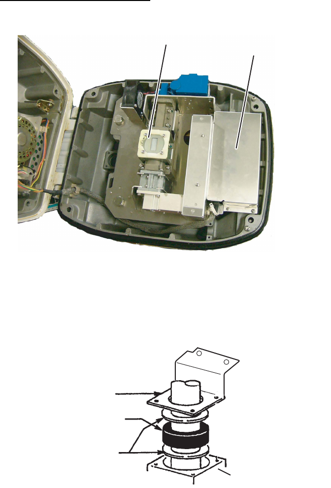
9. Attach three EMI cores to the signal cable as shown below.
Antenna unit chassis, cover opened
10. Fix the signal cable with the cable clamp as follows.
a) Dismount the cable clamp plate and remove clamp and gasket.
EMI Core RFC-13 (2 pcs) EMI Core RFC-H13 (1 pc)
Remove gasket.
Remove clamp.
Cable clamp plate
1. HOW TO INSTALL THE SYSTEM
18
b) Run the signal cable as shown below.
c) Fix the signal cable with cable clamp as shown below.
11. Release the stay and close the cover. Loosely fasten the antenna bolts; you will
have to make some adjustments inside after completion of wiring.
Note: When you close the cover, set the gaskets to the grooves in the bottom chassis,
then tighten the bolts.
Cable clamp
RTB board cover
Top view
Bottom
Chassis
Gasket
Groove
Antenna Bolt
Torque : 9.8 ±0.1 Nm
1. HOW TO INSTALL THE SYSTEM
19
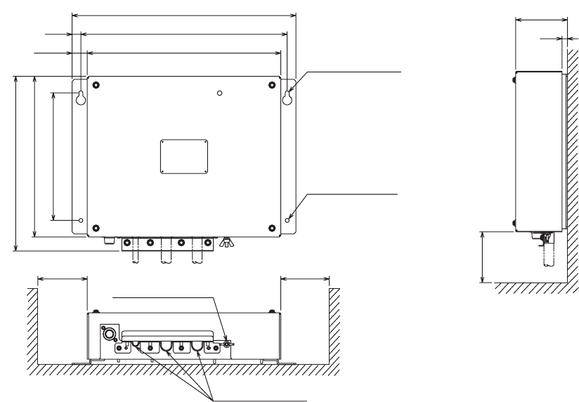
1.3 Power Supply Unit
A power supply unit is shipped with the FR-8255, because of its high power consump-
tion.
The power supply unit can be installed almost anywhere provided the location is dry,
well-ventilated, sufficient maintenance space is provided and is installed within 5 m
(cable length) from the display unit. To fix the unit, use four self-tapping screws (5x20).
Note: Do not install the power supply unit on the overhead; install it on the deck or
bulkhead.
Power supply unit
#200
2 -
ø
6
13
22.5
333
370 ± 0.5
288
2 - R3
FIXING NOTCH
FIXING HOLES
190 ± 0.5
239
260
77
8
CABLE ENTRY
GND TERMINAL
#100 #100
#: Service space