Furuno USA 9ZWRTR088B Transceiver for Radar model FR-8045 User Manual
Furuno USA Inc Transceiver for Radar model FR-8045
Contents
User Manual II Part 2
1. OPERATION
1-21
1.19 Target Alarm
The target alarm looks for targets (ship, landmass, etc.) in the area you set. When a
target enters or exits the alarm area, audiovisual alarms are released.
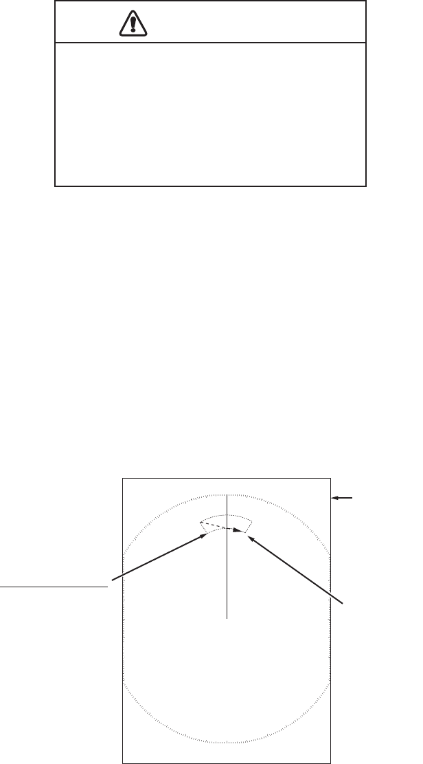
1.19.1 How to set a target alarm zone
The following procedure shows you how to set a target alarm zone.
1. Press the TARGET ALARM key to activate ALARM 1 or ALARM 2. Press the
TARGET ALARM key to change the active ALARM between No. 1 and No. 2. The
indication of the currently active ALARM is in a rectangle at the upper-right corner
of the screen.
2. Use the CursorPad to move the cursor to the position A and press the ENTER
key.
3. Move the cursor to the position B and press the ENTER key. The rectangle that
shows alarm status indication at the upper-right corner of the screen disappears.
(See figure below)
Note 1: To set a 360-degree guard zone, set the position B in the same bearing as the
position A.
Note 2: When the target alarm zone is not within the range in use, the indica-
tion"ALM1(or 2)_RNG" replaces "ALM1(or 2)_IN(or OUT)" in the alarm status area.
(When the target alarm zone is within the range of full off-centering, the indication
does not change.) Select a range which displays the target alarm zone.
CAUTION
CAUTION
· Do not depend on the alarm as the only
means to detect possible collision
situations.
· Adjust the A/C SEA, A/C RAIN and GAIN
controls correctly so that the alarm
system does not miss the target echoes.
Cursor
+
Target alarm zone 1
(Length of dash
and interval for
alarm zone 2 are
longer than alarm
zone 1.)
AB
Alarm status
ALM1_IN
ALM2_OUT
1. OPERATION
1-22
1.19.2 How to stop the audio alarm
When a target enters (or exits) the target alarm zone, the target flashes and the alarm
sounds. The alarm message appears at the bottom of the screen. To stop the audio
alarm, press any key. When the target enters (or exits) the target alarm zone again,
the audio alarm sounds.
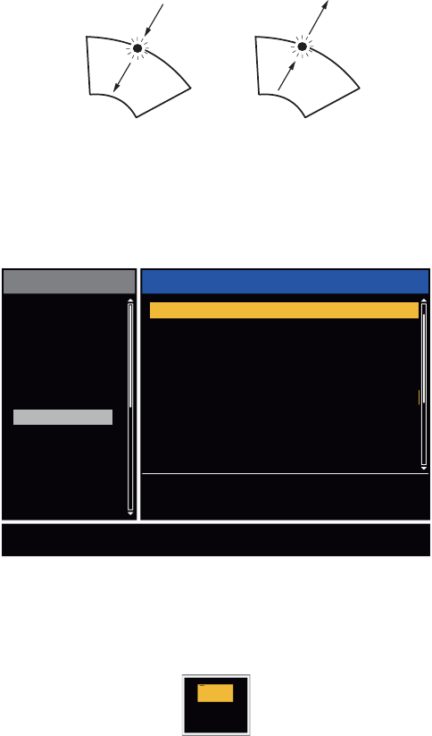
1.19.3 How to select the alarm type
You can set the target alarm to activate against targets which enter or exit the alarm
zone.
In and Out target alarms
1. Press the MENU key to open the menu.
2. Use S or T to select [Alarm] and press the ENTER key.
Alarm menu
3. Use S or T to select [Target Alarm 1] or [Target Alarm 2] then press the ENTER
key.
Target Alarm options
4. Use S or T to select [In] or [Out].
[In]: When the targets enter a target alarm zone, the alarm sounds.
[Out]: When the targets exit a target alarm zone, the alarm sounds.
5. Press the ENTER key followed by the MENU key.
“In” target alarm
“Out” target alarm
[ENTER]: Enter
[MENU]: Exit
[CANCEL/HL OFF]: Back
Brill/Color
Display
Echo
Custom 1
Custom 2
Custom 3
Alarm
Target Trails
Tuning
Target
Others
Menu Echo
Choosing the type (in/out) of target alarm 1
Target Alarm 1
Target Alarm 2
Alarm Level
Watchman
Panel Buzzer
Alarm Status
: In
: In
: Med
: Off
: On
External Buzzer : On
In
Out

1. OPERATION
1-23
1.19.4 How to sleep a target alarm temporarily
When you do not require a target alarm temporarily, you can sleep the target alarm.
The alarm zone remains on the screen, but, any targets that enter or exit the alarm
zone do not trigger the audio and visual alarms.
1. Press the TARGET ALARM key to select the ALARM 1 or ALARM 2 indication at
the upper-right corner on the screen. The selected indication is in a rectangle.
2. Press the CANCEL/HL OFF key. The alarm indication now shows "ALM1(or
2)_ACK".
To activate a sleeping target alarm zone, press the TARGET ALARM key to select the
ALARM 1 or ALARM 2 and press the ENTER key. The alarm indication then changes
to "ALM1(or 2)_IN(or OUT)".
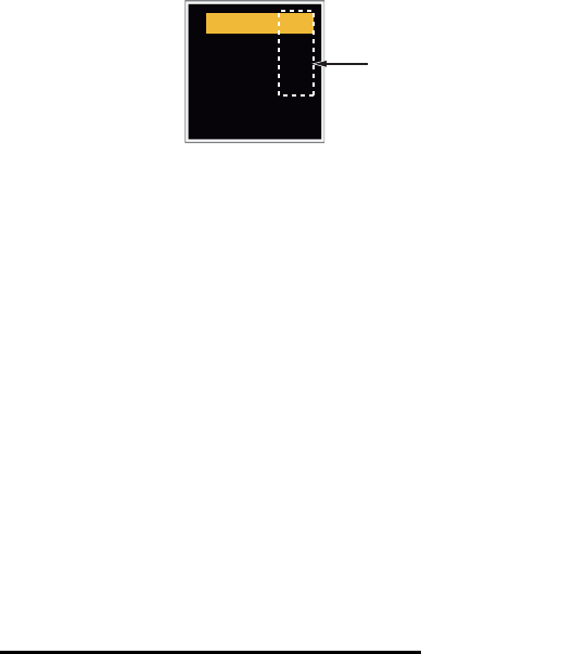
1.19.5 How to deactivate a target alarm
1. Press the TARGET ALARM key to select the ALARM 1 or ALARM 2 indication at
the upper-right corner on the screen. The selected indication is in a rectangle.
2. Press the CANCEL/HL OFF key. The alarm indication now shows "ALM1(or
2)_ACK".
3. Press the TARGET ALARM key. The alarm indication "ALM1(or 2)_ACK" is
shown in a dashed-line rectangle.
4. Press the CANCEL/HL OFF key. The target alarm zone and the alarm indication
are erased from the screen.
1.19.6 How to select the target strength which triggers a target alarm
You can select the target strength which triggers the target alarm as follows:
1. Press the MENU key to open the menu.
2. Use S or T to select [Alarm] and press the ENTER key.
3. Use S or T to select [Alarm Level] and press the ENTER key.
4. Use S or T to select the echo strength level.
5. Press the ENTER key followed by the MENU key.
1.19.7 How to turn the buzzer on/off
You can turn on/off the panel buzzer or external buzzer for target alarms. The panel
buzzer is for this equipment. The external buzzer is for the optional buzzer, which is
connected to this equipment to give the target alarm at a remote location.
1. Press the MENU key to open the menu.
2. Use S or T to select [Alarm] and press the ENTER key.
3. Use S or T to select [Panel Buzzer] (or [External Buzzer] for optional
buzzer) and press the ENTER key.
4. Use the S or T to select [On] or [Off] then press the ENTER key.
5. Press the MENU key to close the menu.
Low
Med
High
Off
On
1. OPERATION
1-24
1.20 How to Off-center the Display
You can off-center your ship position to expand the view field without selecting a larger
range scale. The display can be off-centered manually, or automatically according to
speed of the ship.
Note: Off-centering is not available in the true motion mode and the 64 NM range
scale or higher.
1.20.1 How to select the off-center mode
1. Press the MENU key to open the menu.
2. Use S or T to select [Display] and press the ENTER key.
3. Use S or T to select [Offcenter Mode] and press the ENTER key.
Offcenter Mode options
4. Use S or T to select [Manual], [Custom] or [Auto] then press the ENTER key.
Press the ENTER key to change between on and off.
5. After setting all options, use the T to select [EXIT? YES] and press the ENTER
key.
6. Press the MENU key to close the menu.
1.20.2 Off-center the display
Press the OFF CENTER key to move your ship position. When you press the OFF
CENTER key continuously, the mode changes in the sequence of OFF → Manual →
Custom → Auto → OFF → Manual → ... (the options available depend on setting se-
lected at step 4 in section 1.20.1). When off-centering is active, "OFFCENT(M)",
"OFFCENT(C)" or "OFFCENT(A)" appears at the upper-left corner on the display.
Manual (Indication: "OFFCENT(M)")
You can move your ship position to the current cursor position on all modes except
true motion, within 75% of the available display area.
1. Press the OFF CENTER key several times until the off-center indication disap-
pears.
2. Put the cursor in the position to off-center the display.
3. Press the OFF CENTER key several times until the indication "OFFCENT(M)" ap-
pears.
Manual
Custom
Auto
EXIT? YES
On
Off
Off
Press the ENTER key
to change between
on and off.

1. OPERATION
1-25
Custom (Indication: "OFFCENT(C)")
You can move your ship position to the position which you pre-set. Follow the proce-
dure shown below to register the cursor position.
1. Press the OFF CENTER key several times until the off-center indication disap-
pears.
2. Put the cursor on the position where to off-center the display.
3. Press the OFF CENTER key several times until the indication "OFFCENT(M)" ap-
pears.
4. Press the MENU key to open the menu.
5. Use S or T to select [Display] and press the ENTER key.
6. Use S or T to select [Save Offcenter] and press the ENTER key. The message
"Complete" appears.
7. Press any key to close the message window.
8. Press the MENU key to close the menu.
To change the mode to custom, press the OFF CENTER key several times until the
indication "OFFCENT(C)" appears.
Auto (Indication: "OFFCENT(A)")
The amount of automatic move is calculated according to speed of the ship. The max-
imum amount is 75% of the range in use. The formula to calculate automatic shift is
shown below.
If the offcenter speed setting is 15 knots and the speed of the ship is 10 knots, for ex-
ample, the amount of move at the stern of your ship will be 50% of the available display
area.
How to select offcenter speed
1. Press the MENU key to open the menu.
2. Use S or T to select [Initial] sub menu in [System] menu and press the ENTER
key.
3. Use S or T to select [Offcenter Speed] and press the ENTER key.
Offcenter Speed setting window
4. Use S or T to select the speed to use and press the ENTER key.
5. Press the MENU key to close the menu.
Offcenter speed setting
X 0.75 = Amount of move (%)
Speed of ship
15kn
(1kn~99kn)

1. OPERATION
1-26
1.21 Zoom
The zoom function expands the length and width of a selected target as much as twice
its normal size, in the zoom window. You select the target to zoom with the zoom cur-
sor.
The ARPA and AIS symbols can be displayed in the zoom window, but are not
zoomed. You can process ARPA and AIS targets that are in the zoom window, in the
same method as on the normal radar display.
There are three types of zoom.
[Relative]: The zoom cursor is fixed to the range and bearing from your ship.
[True]: The zoom cursor is fixed to a set geographical position.
[Target]: The zoom cursor is fixed to the zoomed AIS ARPA target.
1.21.1 Zoom mode
You can select the zoom mode from [Relative], [True] or [Target].
1. Press the MENU key to open the menu.
2. Use S or T to select [Display] and press the ENTER key.
3. Use S or T to select [Zoom Mode] and press the ENTER key.
Zoom Mode options
4. Use S or T to select [Relative], [True] or [Target] then press the ENTER key.
Note: True zoom mode requires a heading signal and position data. If either sig-
nal is lost, true zoom mode is cancelled.
5. Press the MENU key to close the menu.
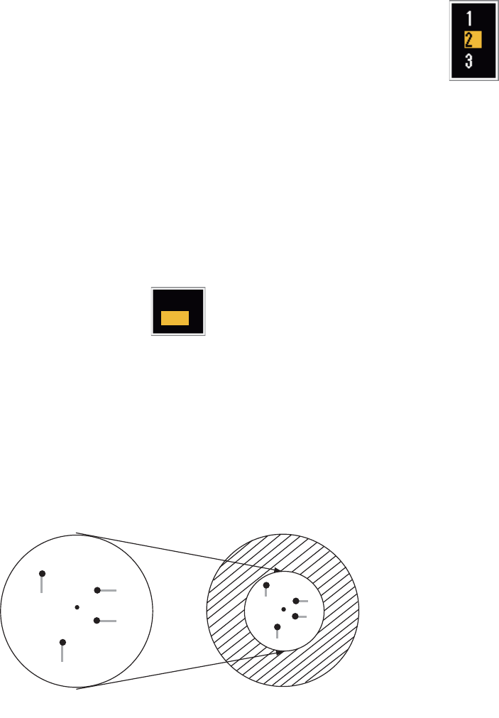
1.21.2 How to zoom
Relative or True zoom mode
1. Use the CursorPad to put the cursor on the position required.
2. Press the MENU key to open the menu.
3. Use S or T to select [Display] and press the ENTER key.
4. Use S or T to select [Zoom] and press the ENTER key.
Zoom options
5. Use S or T to select [On] and press the ENTER key. The ZOOM indication ap-
pears at the upper-left corner on the screen. The zoom window and the zoom cur-
sor also appear (see the illustration on the next page). To quit the zoom, select
[Off] instead of [On] and press the ENTER key.
6. Press the MENU key to close the menu.
Relative
True
Target
Off
On
1. OPERATION
1-27
Target zoom mode
The zoom window can display the ARPA or AIS target, as shown below.
ARPA: The symbol is enlarged twice its normal size.
AIS: The symbol is shown inside a broken square. (The symbol is not enlarged.)
The zoom cursor moves with the ARPA or AIS target.
Note: If neither ARPA nor AIS target is selected, the message "NO TARGET." ap-
pears. Press any key to erase the message.
1. Press the MENU key to open the menu.
2. Use S or T to select [Display] and press the ENTER key.
3. Use S or T to select [Zoom] and press the ENTER key.
4. Use S or T to select [On] and press the ENTER key.
The ZOOM indication appears at the upper-left corner on the screen. The zoom
window and the zoom cursor also appear (see the following illustration). To quit
the zoom, select [Off] instead of [On] and press the ENTER key.
5. Press the MENU key to close the menu.
1.5
1.5
NM
NM
Zoom window
255.5
°
R
1.094
NM
ZOOM(T)
+
Zoom cursor
Zoom indication
VECT
TRUE
05:00
+
1.5
1.5
NM
NM
255.5
°
R
1.094
NM
ZOOM(T)
+
VECT
TRUE
05:00
+
Relative or True zoom mode
(example: true zoom)
Target zoom mode
(example: AIS)
999999000
999999000

1. OPERATION
1-28
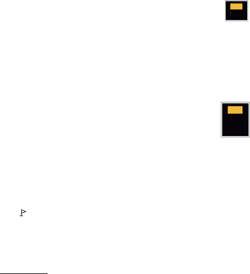
1.22 Echo Stretch
The echo stretch feature enlarges the targets in the range and bearing directions to
make the targets easier to see. This feature is available on any range. There are three
levels of echo stretch, [1], [2] and [3]. [3] enlarges the targets the most.
Note: The echo stretch enlarges the targets, sea and rain clutters, and radar interfer-
ence. Correctly adjust the sea clutter, rain clutter and radar interference before you ac-
tivate the echo stretch.
1. Press the MENU key to open the menu.
2. Use S or T to select [Echo] and press the ENTER key.
3. Use S or T to select [Echo Stretch] and press the ENTER key.
Echo Stretch options
4. Use S or T to select an echo stretch option and press the ENTER key.
5. Press the MENU key to close the menu. When the echo stretch is active, "ES 1
(2, or 3)" appears at the lower-left corner on the display.
1.23 Echo Average
To identify true target echoes from the sea clutter, echoes are averaged over succes-
sive picture frames. If an echo is solid and stable, the echo is shown in its normal in-
tensity. The brilliance of sea clutter is reduced to easily identify true targets from the
sea clutter.
Note 1: Do not use the echo average function under heavy pitching and rolling. You
can lose a target.
Note 2: This feature requires a heading signal and position data. When either signal
becomes lost, echo average is deactivated.
To correctly use the echo average function, first reduce the sea clutter with the A/C
SEA control, then do as follows:
1. Press the MENU key to open the menu.
2. Use S or T to select [Echo] and press the ENTER key.
3. Use S or T to select [Echo Average] and press the ENTER key.
Echo Average options
Off
1
2
3
Off
1
2
Auto

1. OPERATION
1-29
4. Use S or T to select an echo averaging option and press the ENTER key.
[Off]: Deactivates the echo average.
[1]: Identify true targets from the sea clutter and reduce the brilliance of echoes
which are not stable.
[2]: Identify true targets from the sea clutter that you cannot reduce the brilliance
with setting 1.
[Auto]: Identify true targets from the sea clutter. Detect the far targets and targets
which are not stable.
5. Press the MENU key to close the menu. The selected echo average ("EAV 1",
"EAV 2" or "EAV(A)") appears at the lower-left corner of the display.
1.24 Target Trails
The trails of the radar targets can be shown with an artificial line to check target move-
ment. The target trails are selected for either relative or true. True motion trails require
a heading signal and position data.
1.24.1 Trail time
1. Press the MENU key to open the menu.
2. Use S or T to select [Target Trails] and press the ENTER key.
3. Use S or T to select [Time] and press the ENTER key.
Time options
4. Use S or T to select time and press the ENTER key. Press the ENTER key to
change between on and off.
5. After setting all options, use the CursorPad (T) to select [EXIT? YES] and press
the ENTER key.
6. Press the MENU key to close the menu.
On
On
On
On
On
On
On
On
15s
30s
1min
3min
6min
15min
30min
Continuous
EXIT? YES
Press the ENTER key
to change between
on and off.
1. OPERATION
1-30
1.24.2 How to start, stop the trails
1. Press the TRAILS key to start the trails and select the trail time. The selected time
with the trail mode is shown at the upper-right corner like the figure shown below.
The available trail time with the TRAILS key changes according to trail times,
which you turn on in section 1.24.1.
Trail indications
2. To change the trail time, press the TRAILS key until the required trail time is dis-
played. The trail length increases with the trail time.
Note 1: To erase the trails, press and hold the TRAILS key until a beep sounds, or
select [All Cancel] on the [Target Trails].
Note 2: To deactivate the trails, press the TRAILS key several times until the trail in-
dications disappear from the display.
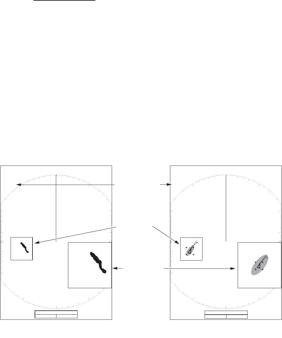
1.24.3 Trail mode
You can display the echo trails in true or relative motion.
True mode
The true trails show true target movements according to their over-the-ground speeds
and courses. The stationary targets do not show the trails. True trails mode requires
heading signal and position data. If either signal is lost, true trail mode is cancelled.
Relative mode
The relative trails show other ships’ movements relative to your ship. The stationary
targets also show the trails.
True trails and relative trails
To select the trail mode, do the following:
1. Press the MENU key to open the menu.
2. Use S or T to select [Target Trails] and press the ENTER key.
TRAIL(T)
15 S
Trail Mode (T: True, R: Relative)
Trail Time
True target trails Relative target trails

1. OPERATION
1-31
3. Use S or T to select [Mode] and press the ENTER key.
Mode options
4. Use S or T to select [Relative] or [True] then press the ENTER key.
5. Press the MENU key to close the menu.
1.24.4 Trail gradation
Trails can be shown in single or multiple gradation. Multiple gradation reduces the gra-
dation over time.
1. Press the MENU key to open the menu.
2. Use S or T to select [Target Trails] and press the ENTER key.
3. Use S or T to select [Gradation] and press the ENTER key.
Gradation options
4. Use S or T to select [Single] or [Multi] then press the ENTER key.
Trail gradation
5. Press the MENU key to close the menu.
1.24.5 Trail color
You can select the color for the trails as follows:
1. Press the MENU key to open the menu.
2. Use S or T to select [Target Trails] and press the ENTER key.
3. Use S or T to select [Color] and press the ENTER key.
Color options
4. Use S or T to select a color and press the ENTER key.
5. Press the MENU key to close the menu.
Relative
True
Single
Multi
Multiple
(Gradual shading)
Single
(Monotone shading)
Green
Red
Blue
White
Black
1. OPERATION
1-32
1.24.6 Trail level
You can select strength at which to display target trails.
1. Press the MENU key to open the menu.
2. Use S or T to select [Target Trails] and press the ENTER key.
3. Use S or T to select [Level] and press the ENTER key.
4. Use S or T to select [1], [2] or [3] then press the ENTER key.
[1]: Display the trails for all targets (including weak targets).
[2]: Display the trails for medium-to-strong level targets.
[3]: Display the trails for only strong targets.
5. Press the MENU key to close the menu.
1.24.7 How to restart, stop the trails
When the range is changed while the trail feature is active, trails within the previous
range scale can be stopped and restarted.
1. Press the MENU key to open the menu.
2. Use S or T to select [Target Trails] and press the ENTER key.
3. Use S or T to select [Restart] and press the ENTER key.
Restart options
4. Use S or T to select [Off] or [On] then press the ENTER key.
[Off]: When the range is changed, the previous trails data are saved. The trails
are not restarted and the saved trails are not updated. When you return the range
scale to the previous range scale, the saved trails are displayed and updated.
[On]: The previous trails are zoomed in or out depending on the changed scale
and updated.
How trail copy operates
Note: If the new range selected is less than or equal to 1/4 of the previous range,
trails are erased. If the new range selected is longer than the previous range, the
previous trails continue to be displayed.
5. Press the MENU key to close the menu.
Off
On
Before changing range After changing range
Copied trail picture
1. OPERATION
1-33
1.24.8 Narrow trails
You can display the target trails in thin trails. When there are many targets on the
screen, you can separate trails near one another with this function.
1. Press the MENU key to open the menu.
2. Use S or T to select [Target Trails] and press the ENTER key.
3. Use S or T to select [Narrow] and press the ENTER key.
4. Use S or T to select [Off] or [On] then press the ENTER key.
5. Press the MENU key to close the menu.
1.24.9 Your ship trail
You can show the trail of your ship as follows:
1. Press the MENU key to open the menu.
2. Use S or T to select [Target Trails] and press the ENTER key.
3. Use S or T to select [Own Ship] and press the ENTER key.
4. Use S or T to select [Off], [1] or [2] then press the ENTER key.
[Off]: Hide the trail of your ship.
[1]: Show the trail of your ship.
[2]: Show the trail of your ship, but hide the trail of sea clutter near
your ship.
5. Press the MENU key to close the menu.
1.25 How to Send the Target Position and Enter the
Origin Mark
The TLL key functions to send the cursor position to a chart plotter and puts an origin
mark ( ) at the cursor position on the radar. Both functions require a heading signal
and position data. If either signal is lost, this function is cancelled. Use the CursorPad
to put the cursor on a target and press the TLL key. You can enter up to 20 origin
marks on the radar display. When the capacity for the origin marks is reached, the old-
est mark is erased to make space for the last mark, to keep a maximum of 20 marks.
To erase a mark, put the cursor on the mark and press the CANCEL/HL OFF key.
TLL key mode
You can select how to handle TLL position.
1. Press the MENU key to open the menu.
2. Use S or T to select [Others] and press the ENTER key.
3. Use S or T to select [TLL Key Mode] and press the ENTER key.
Off
On
Off
1
2

1. OPERATION
1-34
4. Use S or T to select [TLL Output], [Origin Mark] or [Both] then press the ENTER
key.
[TLL Output]: Send the latitude and longitude of the cursor position to a chart
plotter. (Position and heading signal are required.)
[Origin Mark]: Enter an origin mark at the cursor position on the radar display.
(Position and heading signal are required.)
[Both]: Send the target position to a chart plotter and enter an origin mark on the
radar display.
5. Press the MENU key to close the menu.
Note: When you turn off the power, all origin marks are deleted and not saved.
1.26 How to Hide the Heading Line Temporarily
The heading line indicates the heading of your ship in all display modes. The heading
line is a line from your ship position to the outer edge of the radar display area. The
heading line appears at zero degrees on the bearing scale in head up and true view
modes. The heading line changes the orientation depending on the ship orientation in
north up and true motion modes and when the course is changed in the course up
mode.
To hide the heading line (and all marks for River and Sea purpose) and display only
targets, press and hold the CANCEL/HL OFF key. To display the heading line again,
release the key.
1.27 Presentation Brilliance
You can adjust the brilliance for the following menu items from the [Brill/Color] menu.
[Echo Brill]: Brilliance for the echoes (setting range: 1 - 8)
[Rings Brill]: Brilliance for the range rings (setting range: Off, 1 - 4)
[Mark Brill]: Brilliance for the marks (EBL, VRM, etc.) (setting range: 1 - 4)
[HL Brill]: Brilliance for the heading line (setting range: 1 - 4)
[Character Brill]: Brilliance for the characters (setting range: 1 - 4)
1.28 Custom Setup
1.28.1 About custom setup
When your navigating environment or task changes, you must adjust the radar. In-
stead of changing radar settings case by case, you can assign the CUSTOM key to
provide best settings for common conditions.
TLL Output
Origin Mark
Both

1. OPERATION
1-35
There are three default custom setups for the internal computer of the radar (see
paragraph 1.28.2 for a description). You can adjust these settings on the [Custom 1],
[Custom 2] and [Custom 3] menus to meet your navigation needs.
To activate a custom setup, press the CUSTOM key. The CUSTOM key switches be-
tween Custom 1, Custom 2 or Custom 3 each time you press the key. (Custom setup
numbers which are turned off are ignored.) The selected custom setup name is shown
at the upper-left corner. To escape from custom setup, operate any control.
1.28.2 Description of custom setup items
Description of custom setup items
Menu item Available settings See section
[Custom1(2 or 3)] Turn on/off each custom program.
[Copy] Copy settings from the [Echo] menu. The message "Com-
plete" appears after the copying is completed.
[Gain Mode] [Auto]: Automatic gain adjustment according to noise level.
[Manual]: Manual gain adjustment section 1.9
[Manual Gain] Copy the current position of the GAIN knob when you do
[Copy]. This item is for read-only.
[Sea Mode]
[Auto]: Automatic sea clutter adjustment according to sea
state.
[Manual]: Manual sea clutter adjustment.
section 1.10
[Auto Sea]
[Coastal]: Suppress both land and sea clutter.
[Advanced]: Automatically discriminate land echoes from
sea reflections to suppress only sea reflections.
section 1.10
[Manual Sea] Copy the current position of the A/C SEA knob when you do
[Copy]. This item is for read-only.
[Rain Mode]
[Auto]: Automatic rain clutter adjustment according to rain
cloud density.
[Manual]: Manual rain clutter adjustment.
section 1.11
[Auto Rain]
[Calm]: For light rain.
[Moderate]: When you can not reduce the rain clutter with
[Calm] mode.
[Rough]: For heavy rain.
section 1.11
[Manual Rain] Copy the current position of the A/C RAIN knob when you do
[Copy]. This item is for read-only.
[A/C Auto] [Off], [On] section 1.12
[Pulse Length] [Short] or [Long], you can select on 1.5, 1.6, 3.0 and 3.2 nm
ranges. section 1.18
[Echo Stretch] [Off], [1], [2], [3] section 1.22
[Echo Average] [Off], [1], [2], [Auto] section 1.23
[Noise Rejector] [Off], [On] section 1.30
[Wiper] [Off], [1], [2] section 1.31
[Int Rejector] [Off], [1], [2], [3] section 1.14
1. OPERATION
1-36
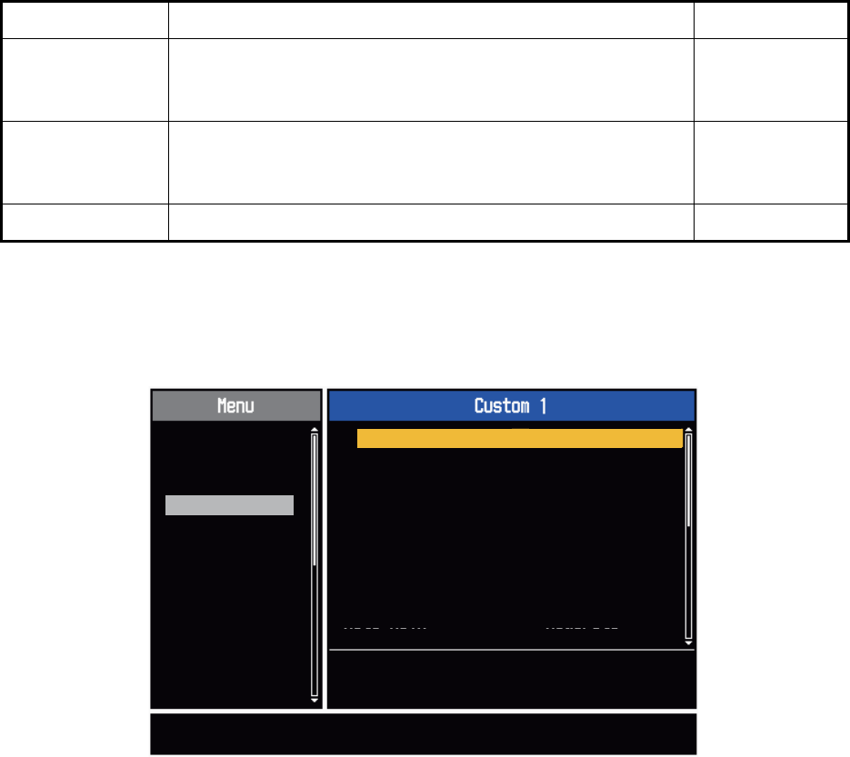
1.28.3 How to set custom setups
1. Press the MENU key to open the menu.
2. Use S or T to select [Custom 1 (2 or 3)] and press the ENTER key.
Custom menu
3. Set menu items.
Note: For easy set up, you can copy the settings of the [Echo] menu (to [Custom
1], [Custom 2], [Custom 3]). Select [Copy] and press the ENTER key. When the
copying is completed, the message "Complete" appears. To erase this message,
press any key.
4. Press the MENU key to close the menu.
[Display-Dynam-
ic]
[Narrow]: Erase weak echoes.
[Normal]: Normal use.
[Wide]: Display weaker echoes compared to [Narrow].
section 1.36
[Display-Curve]
[1]: Reduce weak echoes.
[2]: Normal use.
[3]: Display weaker echoes in stronger color compared to [1].
section 1.37
[Color Erase] 0 - 11 section 1.44.3
Menu item Available settings See section
[ENTER]: Enter
[MENU]: Exit
[CANCEL/HL OFF]: Back
Brill/Color
Display
Echo
Custom 1
Custom 2
Custom 3
Alarm
Target Trails
Tuning
Target
Others
Copy
Gain Mode
Manual Gain
Manual Sea : 0
: Manual
: 0
: Manual
Auto Sea : Advanced
Sea Mode
Rain Mode
Auto Rain
: Manual
: Moderate
Custom1 : On
Enable/Disable the custom settings

1. OPERATION
1-37
1.29 How to Program Function Keys (F1, F2 and F3
keys)
You can program function keys (F1, F2 and F3) to provide one-touch access to a re-
quired function.
Function key operation
To activate a function, press function key, F1, F2 or F3. Press same key to change the
setting.
The default programs are [Gain Mode] for F1, [Sea Mode] for F2, [A/C Auto] for F3.
When you press the F1 or F2 key, the window for Gain/Sea/Rain indicator shows. See
section 1.9 and section 1.10 for operation. When you press the F3 key, [A/C Auto] is
turned on.
How to change a function key program
1. Press the MENU key to open the menu.
2. Use S or T to select [Others] and press the ENTER key.
3. Use S or T to select [F1 (F2 or F3) Setup] and press the ENTER key.
4. Use S or T to select a function from the list and press the ENTER key. Below are
the available functions.
Function list
5. Press the MENU key to close the menu.
Rings Brill
Mark Brill
HL Brill
Character Brill
Echo Shading
Display Color
Echo Color
Background Color
Character Color
Menu Transparency
Echo Color Mode
Display Mode
Zoom
Zoom Mode
Echo Area
Data Box
STBY Display
Gain Mode
Sea Mode
Auto Sea
Rain Mode
Auto Rain
A/C Auto
Pulse Length
Echo Stretch
Echo Average
Noise Rejector
Wiper
Int Rejector
Display-Dynamic
Display-Curve
2nd Echo Rejector
Target Alarm 1
Target Alarm 2
Alarm Level
Watchman
Panel Buzzer
External Buzzer
Trails-Gradation
Trails-Color
Trails-Mode
Trails-Level
Trails-Restart
Trails-Narrow
Trails-Own Ship
Tuning Mode
WPT Mark
EBL Reference
VRM Unit
Cursor Position
TLL Key Mode
Vector Reference
History Dots
History Interval
CPA
TCPA
Proximity
ARPA-Display
ARPA-Color
ARPA-Auto Acquisition
ARPA-ACK Lost Targets
AIS-Display
AIS-Color
AIS-Sort By
AIS-ACK Lost Targets
GPS-Mode
GPS-Datum
GPS-WAAS
1. OPERATION
1-38
1.30 Noise Rejector
White noise can appear on the screen as random "marks". You can reduce this noise
as follows:
1. Press the MENU key to open the menu.
2. Use S or T to select [Echo] and press the ENTER key.
3. Use S or T to select [Noise Rejector] and press the ENTER key.
Noise Rejector options
4. Use S or T to select [Off] or [On] then press the ENTER key.
5. Press the MENU key to close the menu.
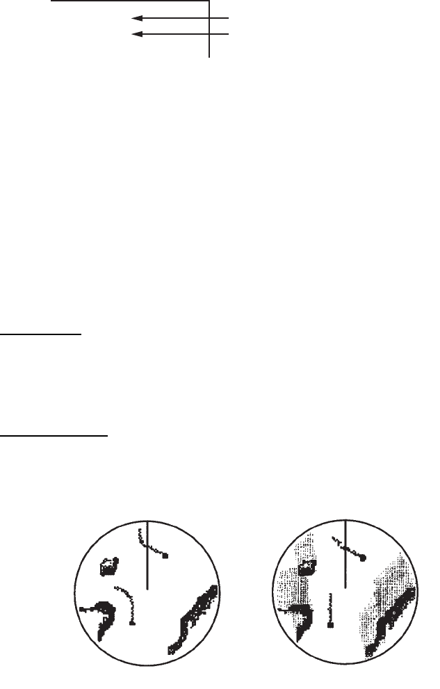
1.31 Wiper
The wiper feature automatically reduces the brilliance of unwanted weak signals
(noise, sea clutter, rain clutter, etc.) and unnecessary signals, like radar interference,
to clear the picture of unnecessary echoes. The result of wiper depends on the wiper
setting used and whether echo averaging is turned on or off, as described below.
Processing content A: The brilliance of unnecessary weak echoes, like noise and ra-
dar interference, is reduced to clear the picture. The difference between wiper 1 and
2 is that brilliance is lowered more slowly in 1.
Processing content B: Echo averaging is automatically turned from off to on when
the wiper feature is turned on. You can see how the picture changes with the echo av-
eraging turned off and turned on.
To activate the wiper feature, do the following:
1. Press the MENU key to open the menu.
2. Use S or T to select [Echo] and press the ENTER key.
3. Use S or T to select [Wiper] and press the ENTER key.
4. Use S or T to select [1] or [2] then press the ENTER key.
5. Press the MENU key to close the menu.
Note: When the [Display Mode] is [True View], this function is not
available (see paragraph 1.7.2).
Wiper 1 Wiper 2
Echo Average Off Processing content A
Echo Average On (1,2, Auto) Processing content A Processing content B
Off
On
Wiper options
1. OPERATION
1-39
1.32 How to Reduce Second-trace Echoes
Echoes from very distant targets can appear as false echoes (second-trace echoes)
on the screen. The second-trace echo occurs when the return echo is received one
transmission cycle later, or after a next transmission of radar pulse.
Second-trace echoes
1. Press the MENU key to open the menu.
2. Use S or T to select [Echo] and press the ENTER key.
3. Use S or T to select [2nd Echo Rejector] and press the ENTER key.
2nd Echo Rejector options
4. Use S or T to select [Off] or [On] then press the ENTER key.
5. Press the MENU key to close the menu.
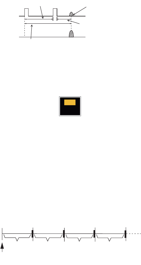
1.33 Watchman
The Watchman sounds the buzzer to tell the operator to check the radar display. The
radar transmits for one minute and then goes into standby for the selected time inter-
val. If the target alarm is active and a target is found in the alarm zone, Watchman is
cancelled, and the radar transmits continuously.
How watchman operates
In standby, the timer near the <WATCH> label at the center of the screen counts down
the remaining time until the transmission. When the set time interval has passed, the
audio alarm sounds, the timer disappears and the radar transmits for one minute. After
one minute, the audio alarm sounds, the radar stops transmitting and the watch alarm
timer again begins the countdown sequence.
If you press the STBY/TX key before the set time interval comes, the radar goes into
transmission.
Second-trace
echo
TX repetition
Actual range
False echo
range
Off
On
ST-BY
5,10 or 20 min.
Tx
1 min.
Watchman
starts
*
* Beep sounds just before radar transmits
or goes into standby.
ST-BY
Tx *
5,10 or 20 min.
1 min.
**
1. OPERATION
1-40
Do the following to activate the Watchman:
1. Press the MENU key to open the menu.
2. Use S or T to select [Alarm] and press the ENTER key.
3. Use S or T to select [Watchman] and press the ENTER key.
Watchman options
4. Use S or T to select [Off] or the time ([5min], [10min] or [20min]) then press the
ENTER key.
5. Press the MENU key to close the menu.
1.34 Color Selections
1.34.1 Preset colors
This radar is preset with color combinations that provide best viewing in day time, night
time and twilight. Below are the default color settings for each display item and display
color setting.
Display item, color design and color
1. Press the MENU key to open the menu.
2. Use S or T to select [Brill/Color] and press the ENTER key.
3. Use S or T to select [Display Color] and press the ENTER key.
Display Color options
4. Use S or T to select the color design and press the ENTER key.
5. Press the MENU key to close the menu.
Display Item Day Night Twilight Custom
Characters Black Red Green Green
Range rings, marks Green Red Green Green
Echo Yellow Green Green Yellow
Background White Black Blue Black
Off
5min
10min
20min
Day
Twilight
Custom
Night

1. OPERATION
1-41
1.34.2 Custom colors
The custom color design lets you select preferred echo, background, characters,
range rings and marks colors. Select [Custom] in the [Display Color] menu item (see
paragraph 1.34.1) to use the user selected echo, background, characters, range rings
and marks colors.
1. Press the MENU key to open the menu.
2. Use S or T to select [Brill/Color] and press the ENTER key.
3. Use S or T to select [Echo Color] and press the ENTER key.
Echo Color options
4. Use S or T to select an echo color and press the ENTER key. [Multi] displays
echoes in colors of red, yellow and green according to echo strength, and [Multi]
is not available in the [IEC] or [Russian-River] mode.
5. Use S or T to select [Background Color] and press the ENTER key.
Background Color options
6. Use S or T to select a background color and press the ENTER key.
7. Use S or T to select [Character Color] and press the ENTER key.
Character Color options
8. Use S or T to select a character color (including range rings and marks) and
press the ENTER key.
9. Press the MENU key to close the menu.
Yellow
Green
Orange
Multi
Black
DK Blue
Blue
White
Red
White
Green
1. OPERATION
1-42
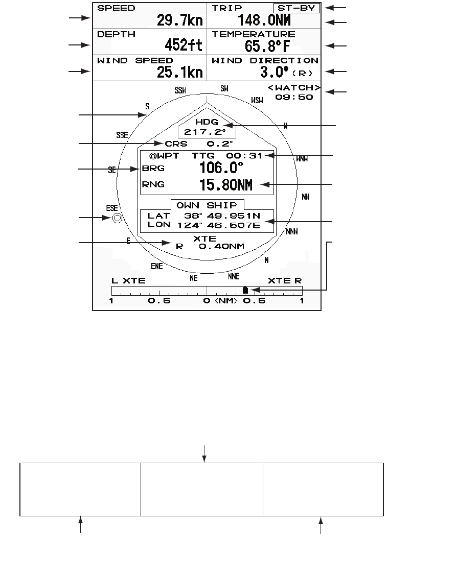
1.35 Navigation Data
1.35.1 Navigation data during standby
The navigation data is shown in standby when [STBY Display] on the [Display] menu
is set to [Nav]. Appropriate sensors are required to display the data.
Navigation data display at standby
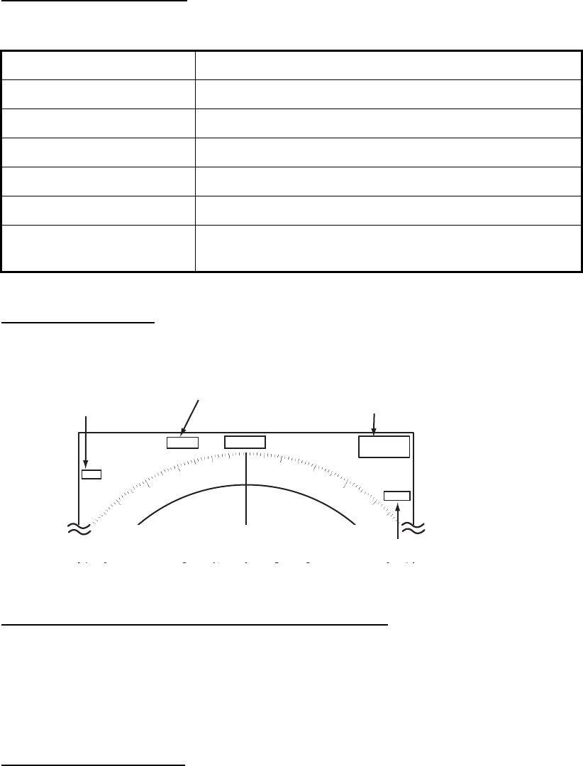
1.35.2 Navigation data at the bottom of the screen
The navigation data is displayed at the bottom of the screen.
Navigation data
Speed Standby indication
Depth Water temperature
Trip
Wind speed Wind direction
Time until TX
in watchman
Heading indicator
Heading
Course
Time to go to
destination waypoint
Bearing to
destination
waypoint Range to go to
destination waypoint
Waypoint mark Your ship position
Cross track error
(numeric value)
Cross track error
(graphic): For example,
when the indicator is off
to the right side, steer
your ship to the left to go
to the destination waypoint.
- Cursor latitude position
- Cursor longitude position
- Time to go to cursor position
Your ship position and speed - Bearing from your ship to waypoint
- Range from your ship to waypoint
- Time to go from your ship position to waypoint
LAT 34°56.123N
LON 135°34.567E
SPEED 12.3KN
LAT 34°56.123N
LON 135°34.567E
TTG 01:00
BRG
14.8°
RNG 0.876NM
TTG
00:20
OWN SHIP + CURSOR WAYPOINT

1. OPERATION
1-43
To show or hide the navigation data at the bottom of the screen, do the following:
1. Press the MENU key to open the menu.
2. Use S or T to select [Display] and press the ENTER key.
3. Use S or T to select [Data Box ] and press the ENTER key.
Data Box options
4. Use S or T to select an option and press the ENTER key.
[Off]: Turn off the data display.
[Nav]: Navigation data
[Target]: ARPA and AIS target data (See section 3.8 and section 4.5.)
[All]: Navigation data plus ARPA and AIS target data
5. Press the MENU key to close the menu.
1.36 Dynamic Range
You can change the dynamic range to erase unwanted weak echoes (sea reflections,
etc.). Select [Narrow], [Normal] or [Wide] depending on conditions.
1. Press the MENU key to open the menu.
2. Use S or T to select [Echo] and press the ENTER key.
3. Use S or T to select [Display-Dynamic] and press the ENTER key.
Display-Dynamic options
4. Use S or T to select [Narrow], [Normal] or [Wide] then press the ENTER key.
[Narrow]: Erase weak echoes.
[Normal]: Normal use
[Wide]: Display weaker echoes compared to [Narrow].
5. Press the MENU key to close the menu.
All
Off
Nav
Target
Narrow
Wide
Normal
1. OPERATION
1-44
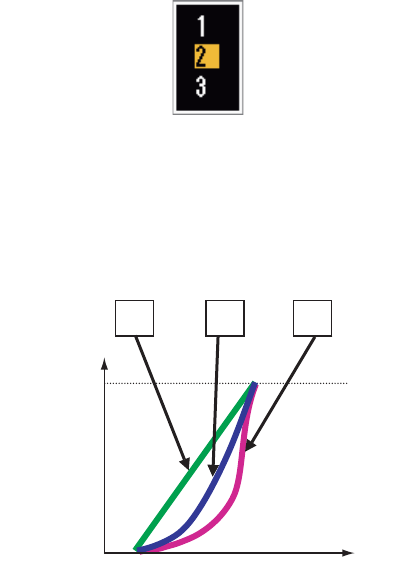
1.37 Characteristics Curve
You can change the characteristics curve to reduce unwanted weak echoes (sea re-
flections, etc.). Select [1], [2] or [3] depending on conditions when unwanted weak
echoes hide wanted targets.
1. Press the MENU key to open the menu.
2. Use S or T to select [Echo] and press the ENTER key.
3. Use S or T to select [Display-Curve] and press the ENTER key.
Display-Curve options
4. Use S or T to select [1], [2] or [3] then press the ENTER key.
[1]: Reduce weak echoes.
[2]: Normal use
[3]: Display weaker echoes in stronger color compared to [1].
Display curve
5. Press the MENU key to close the menu.
321
Input level
Echo color
strength
Strong
Strong
1. OPERATION
1-45
1.38 Waypoint Marker
The waypoint marker shows the location of the destination waypoint set on a naviga-
tion plotter. The heading signal or course data are required. You can turn on/off the
waypoint marker as follows:
Waypoint marker
1. Press the MENU key to open the menu.
2. Use S or T to select [Others] and press the ENTER key.
3. Use S or T to select [WPT Mark] and press the ENTER key.
WPT Mark options
4. Use S or T to select [Off] or [On] then press the ENTER key.
5. Press the MENU key to close the menu.
1.39 Alarm Message
The alarm status window shows all current alarms.
Note: The alarm status window is not automatically displayed when an alarm occurs.
1. Press the MENU key to open the menu.
2. Use S or T to select [Alarm] and press the ENTER key.
+
Waypoint
marker
Off
On

1. OPERATION
1-46
3. Use S or T to select [Alarm Status] and press the ENTER key.
4. Press the CANCEL/HL OFF key to close the alarm status display.
5. Press the MENU key to close the menu.
Alarm category Meaning
SIGNAL MISSING*
"TRIGGER" Trigger signal lost (only for remote display)
"HEADING" Heading signal lost
"BEARING" Bearing signal lost
"GYRO" AD-10 format gyro signal lost
"VIDEO" Video signal lost
"POSITION" NMEA format position data lost
"NMEA_HDG" NMEA format heading signal lost
TARGET ALARM1(2)
"IN" An echo has entered a target alarm zone.
"OUT" An echo has exited a target alarm zone.
ARPA ALARM
"COLLISION" CPA and TCPA of an ARPA target are less than CPA and
TCPA alarm settings.
"LOST" The acquired ARPA target becomes lost.
"PROXIMITY" The range to an ARPA target is less than the user-set
proximity alarm range.
AIS ALARM
"COLLISION" CPA and TCPA of an AIS target are less than CPA and
TCPA alarm settings.
"PROXIMITY" The range to an AIS target is less than the user-set prox-
imity alarm range.
AIS SYSTEM*
"TX" TX stopped or TX error
"FAIL" System failure
"ANT" Antenna VSWR problem
"CH1" TDM2 RX1 board problem
"CH2" TDM2 RX2 board problem
"CH70" RX channel 70 problem
"MKD" Minimum input device lost
"EPFS" Navigator (GPS, etc.) problem
"L/L" Position data lost
"SOG" Speed data lost
Continued on following page
TRIGGER HEADING BEARING GYRO
VIDEO POSITION NMEA_HDG
IN OUT
IN OUT
COLLISION LOST PROXIMITY
COLLISION PROXIMITY
TX ANT CH1 CH2 CH70 FAIL MKD
EPFS L/L SOG COG HDG ROT
OVER_TEMP
[SIGNAL MISSING]
[TARGET ALARM1]
[TARGET ALARM2]
[ARPA ALARM]
[AIS ALARM]
[AIS SYSTEM]
[OTHER]
Alarm Status
[CANCEL/HL OFF]: Close
1. OPERATION
1-47
*: Have a qualified technician check the equipment.
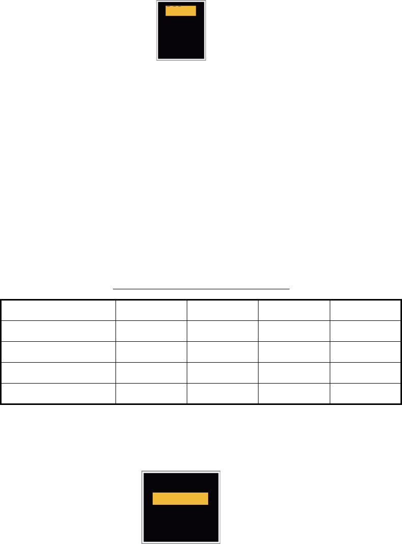
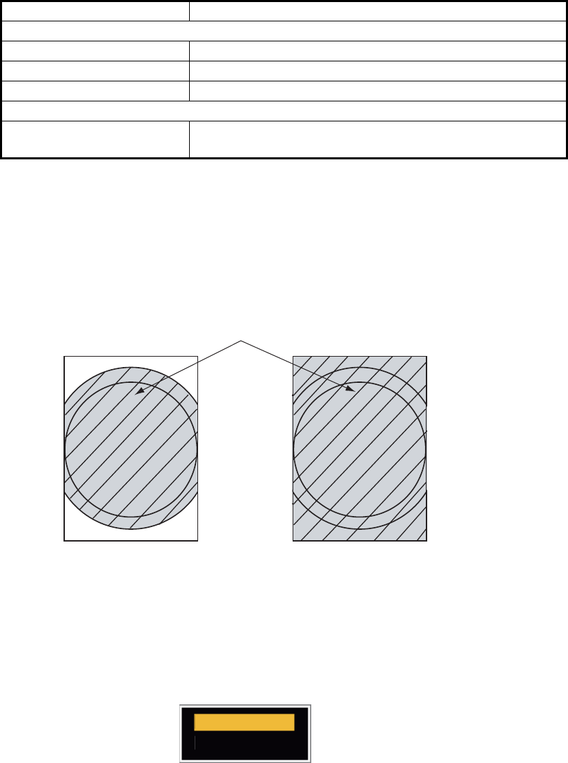
1.40 Echo Area
You can select the display area from [Normal] or [Full Screen] to observe a wider over-
view of the surrounding area.
Echo area
1. Press the MENU key to open the menu.
2. Use S or T to select [Display] and press the ENTER key.
3. Use S or T to select [Echo Area] and press the ENTER key.
Echo Area options
4. Use S or T to select [Normal] or [Full Screen] then press the ENTER key.
5. Press the MENU key to close the menu.
Continued from previous page
"COG" Course data lost
"HDG" Heading data lost
"ROT" Rate of turn data lost
OTHER*
"OVER_TEMP" The temperature of the equipment is more than the spec-
ified value.
Alarm category Meaning
Normal Full Screen
Area in which echoes are displayed
Normal
Full Screen

1. OPERATION
1-48
1.41 Initial Sub Menu
The [Initial] sub menu in the [System] menu contains the items which allow you to ad-
just your radar to meet your needs.
1.41.1 How to open the Initial sub menu
1. Press the MENU key to open the menu.
2. Use S or T to select [Initial] and press the ENTER key.
Initial sub-menu
1.41.2 Description of Initial sub menu
[Key Beep]: When a key is pressed, a beep sounds. You can turn the beep on or off.
[Offcenter Speed]: Set the speed of your ship to calculate amount of your ship’s off-
center. The setting range is 1-99 (kn).
[Compass Type]: Select the type of bearing sensor connected to the radar; [True]
(gyrocompass, satellite compass) or [Magnetic] (magnetic compass).
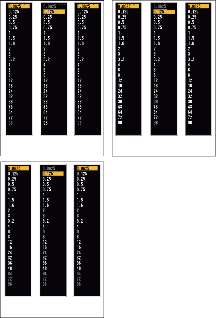
[Range Preset]: You can select the radar ranges. Select a range and press the
ENTER key to switch on and off. See figure on following page for reference.
(Not available in Russian River or IEC modes.)
[Wind Direction]: The wind direction is shown as [Apparent] or [True].
[NMEA Port 1]: Set the baud rate of the equipment connected to Port 1 ([Auto],
[4800], or [38400] (bps)). [Auto] provides automatic detection of baud rate from [4800],
[9600], [19200] or [38400] (bps).
[NMEA Port 2]: Same function as Port 1 but for Port 2.
[NMEA Mixing Out]: Data input to Port 1 may be output from Port 2 mixed with data
output to Port 2. Select [On] to use this feature.
Note: At least two ranges must be turned on in the [Range Preset] menu. The maxi-
mum range available depends on the radar model.
0.0625 is not available in KM (kilometers). Available ranges are shown on the next
page.
Menu Initial
[ENTER]: Enter
[MENU]: Exit
[CANCEL/HL OFF]: Back
Others
Target
ARPA
AIS
GPS
System
Initial
Tests
Sector Blanks
Units
Key Beep
Offcenter Speed
Compass Type
Range Preset
NMEA Port 2
: Off
: 15kn
: True
: Off
: Apparent
NMEA Port 1 : Auto
Wind Direction
NMEA Mixing Out
: Auto
Turning on/off beep sounds
1. OPERATION
1-49
NM
(Nautical Miles)
KM
(Kilometers)
SM
(Statute Miles)
OffOff
On
On
On
On
On
On
On
On
On
On
On
On
On
Off
Off
Off
Off
Off
Off
Off
Off
Off
Exit? Yes Exit? Yes
On
On
On
On
On
On
On
On
On
On
On
On
On
Off
Off
Off
Off
Off
Off
Off
Off
Off
Off
Exit? Yes
On
Off
Off
Off
Off
Off
Off
Off
Off
Off
Off
On
On
On
On
On
On
On
On
On
On
On
On
Available ranges for FR-8065/FR-8125
NM
(Nautical Miles)
KM
(Kilometers)
SM
(Statute Miles)
Available ranges for FR-8255
Off
On
On
On
On
On
On
On
On
On
On
On
On
On
Off
Off
Off
Off
Off
Off
Off
Off
Exit? Yes
On
Off
Off
On
On
On
On
On
On
On
On
On
On
On
Off
Off
Off
Off
Off
Off
Off
Off
Exit? Yes
On
On
Off
On
On
On
On
On
On
On
On
On
On
On
On
Off
Off
Off
Off
Off
Off
Off
Off
Exit? Yes
On
On
Available ranges for FR-8045
NM
(Nautical Miles)
KM
(Kilometers)
SM
(Statute Miles)
On
On
On
On
On
On
On
On
On
On
Off
Off
Off
Off
Off
Off
Off
Off
Off
Off
Off
Off
Exit? Yes
On On
On
On
On
On
On
On
On
On
On
Off
Off
Off
Off
Off
Off
Off
Off
Off
Off
Off
Off
Exit? Yes
On
On
On
On
On
On
On
On
On
On
On
Off
Off
Off
Off
Off
Off
Off
Off
Off
Off
Off
Off
Exit? Yes
On

1. OPERATION
1-50
1.42 Units Sub Menu
You can select the unit of measurement for range, ship speed, depth, temperature and
wind speed on the [Units] sub menu in the [System] menu. You can not open this sub
menu in normal operation. To open this menu, select [Units], hold the CANCEL/HL
OFF key and press the MENU key five times.
Units sub menu
[Range Unit]: NM, KM, SM
When using IEC or Russian River mode, Range Unit can only be changed with the unit
in standby.
[Ship Speed Unit]: kn, km/h, mph
[Depth Unit]: m, ft, fa, pb, HR
[Temperature Unit]: °C, °F
[Wind Speed Unit]: kn, km/h, mph, m/s
Initial
Tests
Sector Blanks
Units
Factory
Installation
ARPA
AIS
GPS
Menu Units
System
Ship Speed Unit
Depth Unit
Temperature Unit
: kn
: ft
: °F
: kn
Wind Speed Unit
Range Unit : SM
[ENTER]: Enter
[MENU]: Exit
[CANCEL/HL OFF]: Back
Choosing a unit of range
1. OPERATION
1-51
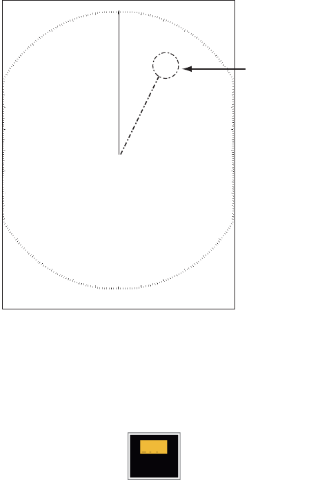
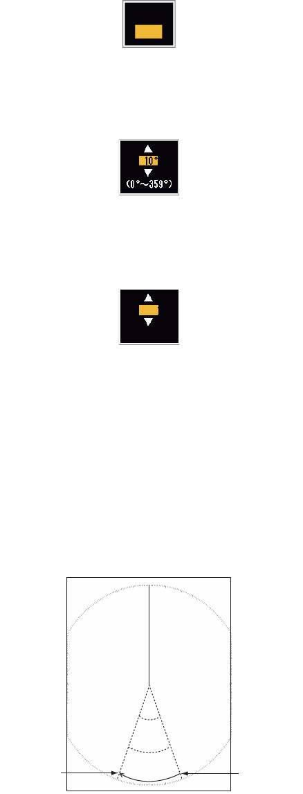
1.43 Sector Blank
You must prevent the transmission in some areas to protect passengers and crew
from microwave radiation. Also, if the reflections of echoes from the mast appear on
the screen, you must prevent the transmission in that area. You can set two sectors.
1. Press the MENU key to open the menu.
2. Use S or T to select [Sector Blanks] and press the ENTER key.
3. Use S or T to select [Sect-Blank 1 (or 2) Status] and press the ENTER key.
Sector-Blank Status options
4. Use S or T to select [On] and press the ENTER key.
5. Use S or T to select [Sect-Blank 1 (or 2) Start] and press the ENTER key.
Sect-Blank Start setting window
6. Use S or T to set the start point of the sector and press the ENTER key.
7. Use S or T to select [Sect-Blank 1 (or 2) End] and press the ENTER key.
Sect-Blank End setting window
8. Use S or T to set the end point of the sector and press the ENTER key.
Note 1: You can not set the sector more than 180 degrees.
Note 2: You can not set the total width of sector 1 and sector 2 more than 270
degrees.
9. Press the MENU key to close the menu.
As shown in the following illustration, dashed lines mark the start and end points of the
sector.
Sector blank
Off
On
250°
(0°~359°)
+
Area of no
transmission
Start bearing
of sector
End bearing
of sector
1. OPERATION
1-52
1.44 Other Menu Items
1.44.1 Menu items on the [Brill/Color] menu
[Echo Shading]: You can adjust the color of the echo shade for better visibility. The
higher the setting, the darker the echo is displayed.
Echo Shading options
[Menu Transparency]: You can select the degree of transparency of the menu win-
dow so the menu window does not hide the echo display. [4] is the greatest degree of
transparency. [Off] functions to hide the echo display behind the menu window com-
pletely.
Note: Alpha blending technology is used for transparency effects.
Menu Transparency options
[Echo Color Mode]: You can select the color palette from [System] or [Custom]. [Sys-
tem] is the pre-set color palette and [Custom] is the color palette you can set yourself.
This function is not available in the [IEC] or [Russian-River] mode.
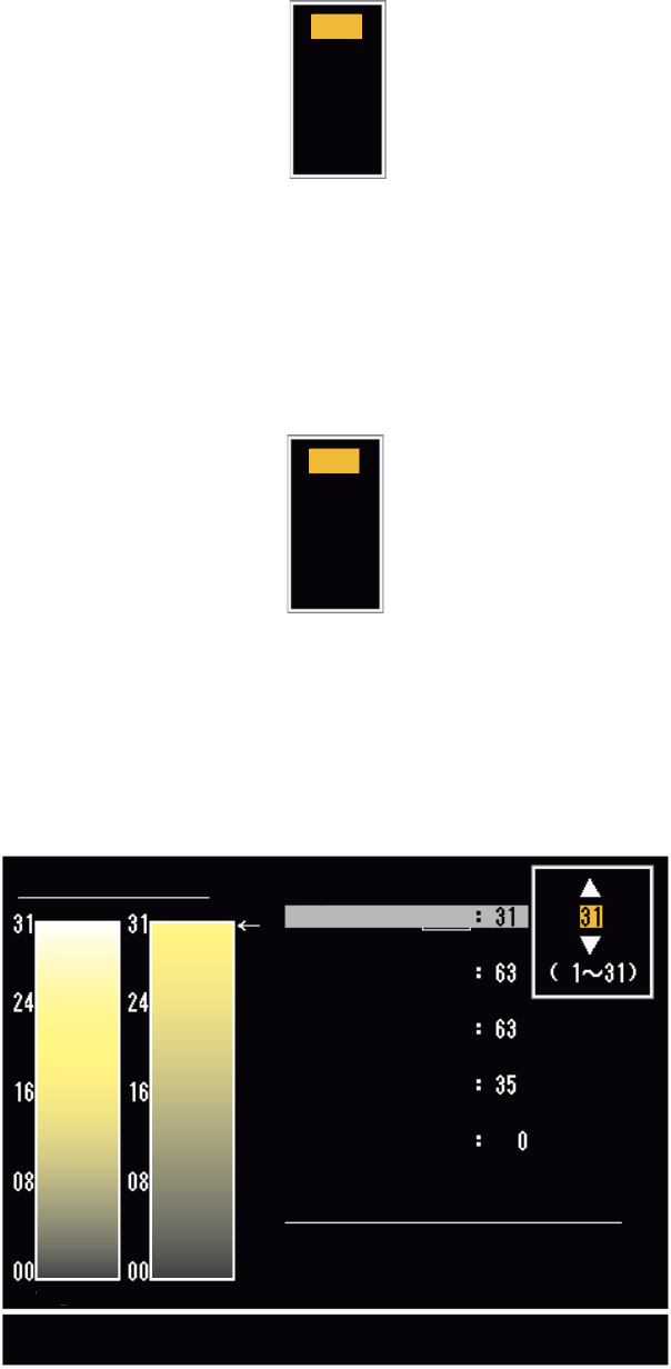
[Custom Echo Color]: You can adjust the echo color with the following two methods.
This function is not available in the [IEC] or [Russian-River] mode.
1
2
3
4
5
Off
1
2
3
4
Custom Echo Color
<System> <Custom>
Customizing echo colors
Rank
Red
Green
Blue
Fitting to Curve
Copy to Custom
Close this Window
1. OPERATION
1-53
Method 1:
1. Select the echo rank to change on the [Rank] (setting range: 1 - 31).
2. Set the RGB values for selected echo rank on the [Red], [Green] and [Blue] (set-
ting range: 0 - 63).
Method 2:
1. Select 31 on the [Rank].
2. Set the RGB values for 31 echo rank on the [Red], [Green] and [Blue] (setting
range: 0 - 63).
3. Interpolate the RGB values between the maximum rank and minimum rank on the
[Fitting To Curve] with the following curves (setting range: -20 to 20).
Setting range > 0: Logarithmic curve, useful to emphasize the weak echoes.
Setting range = 0: Straight line
Setting range < 0: Exponential curve, useful to emphasize the strong echoes.
[Copy To Custom]: Copy the color palette from [System] to [Custom].
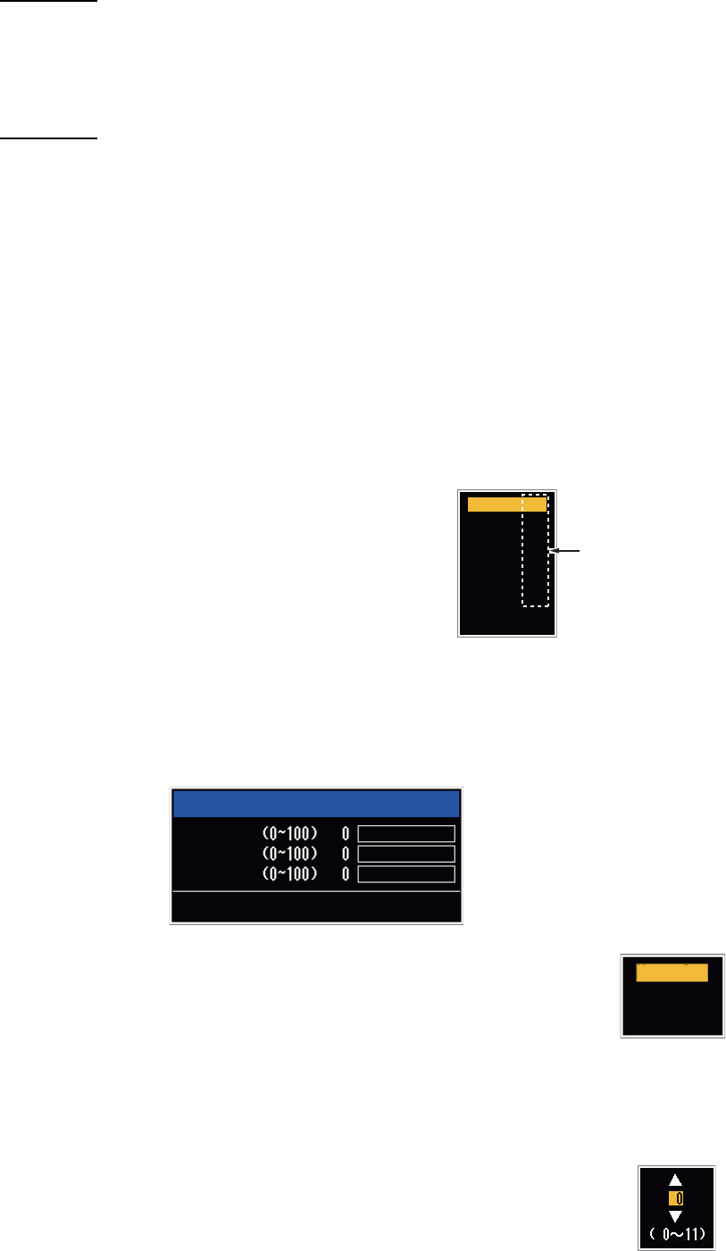
1.44.2 Menu items on the [Display] menu
[Base Text Display]: You can select on/off for the
text indications of the following items on the dis-
play. The settings on this function are used when
you set [Echo Area] to [Full Screen] on the [Dis-
play] menu. This function is not available in the
[IEC] or [Russian-River] mode.
The text indications set to off appear when you op-
erate any key. The indications disappear when there is no key operation for 10 sec-
onds.
[Gain/Sea/Rain Bar]: Open the Gain/Sea/Rain indicator. You can check the current
settings.
[STBY Display]: Set the function of the standby display.
[Normal]: Display "ST-BY" at the screen center.
[Nav]: Display navigation data.
[Economy]: Turn off the backlight of the LCD. The radar must be
switched from TX to ST-BY to activate this mode.
1.44.3 Menu items on the [Echo] menu
[Color Erase]: Erase the lower echo color whose level is set here. Set
a large value to display only the stronger echoes.
Range On
On
On
On
On
On
Mode
Alarm
Echo
EBL/VRM
+Cursor
EXIT? YES
Press the ENTER key
to change between
on and off.
Gain/Sea/Rain
GAIN MAN
SEA MAN
RAIN MAN
[CANCEL/HL OFF]: Close
Normal
Nav
Economy
1. OPERATION
1-54
1.45 Remote Display
You can use this radar as a remote display when you set [Input Source] to [Slave] on
the [Installation] sub menu. When this setting is done, the menu and display change
as described below. To display the radar image on the remote display, transmit from
the main radar.
Note: The message "Please turn to STBY-mode when you change this setting." ap-
pears when you switch the mode in transmission.
Unavailable menu items
The menu items not available with the remote display are shown in the table.
Display appearance
The display changes as shown in the following illustration.
Transmitting or standby display indications for remote display
Items unavailable with Function key F1, F2 and F3
• [Pulse Length] ([Echo] menu)
• [2nd-Echo Rejector] ([Echo] menu)
• [Watchman] ([Alarm] menu)
• [Tuning Mode] ([Tuning] menu)
Total TX time indication
The total TX time (TX TIME XXXXXX.XH) does not appear on the diagnostic test or
on the Normal standby display.
Menu Unavailable menu item(s)
[Echo] [Pulse Length], [2nd Echo Rejector]
[Custom 1, 2, 3] [Pulse Length]
[Alarm] [Watchman]
[Tuning] All menu items are not accessible.
[System] - [Sector Blanks] All menu items are not accessible.
[System] - [Installation] [Antenna Rotation], [MBS Adjust], [Auto Install Setup],
[Total TX Time]
HDG
OFFCENT(M)
Shown when display
unit functions as
remote display.
Tuning indicator
is not displayed.
Pulselength
is not displayed.
WTC is not displayed.
SLAVE
0.5
NM
0.125
CS1
H UP
TRAIL(T)
06MIN
ALM1_ACK
ALM2_OUT
359.9°