Furuno USA 9ZWRTR088B Transceiver for Radar model FR-8045 User Manual

Furuno USA Inc Transceiver for Radar model FR-8045

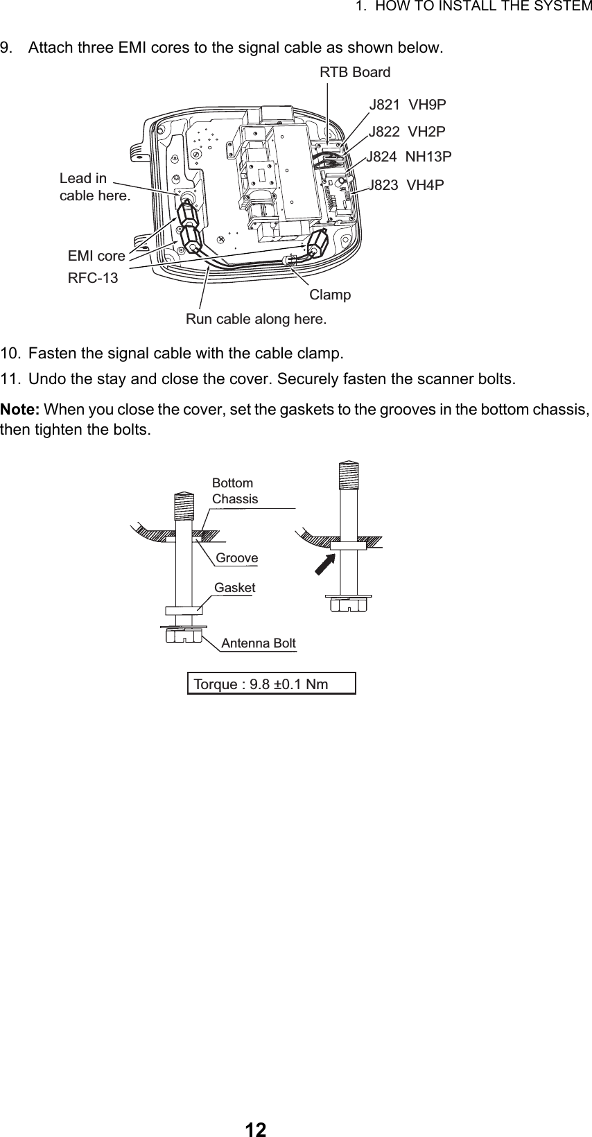
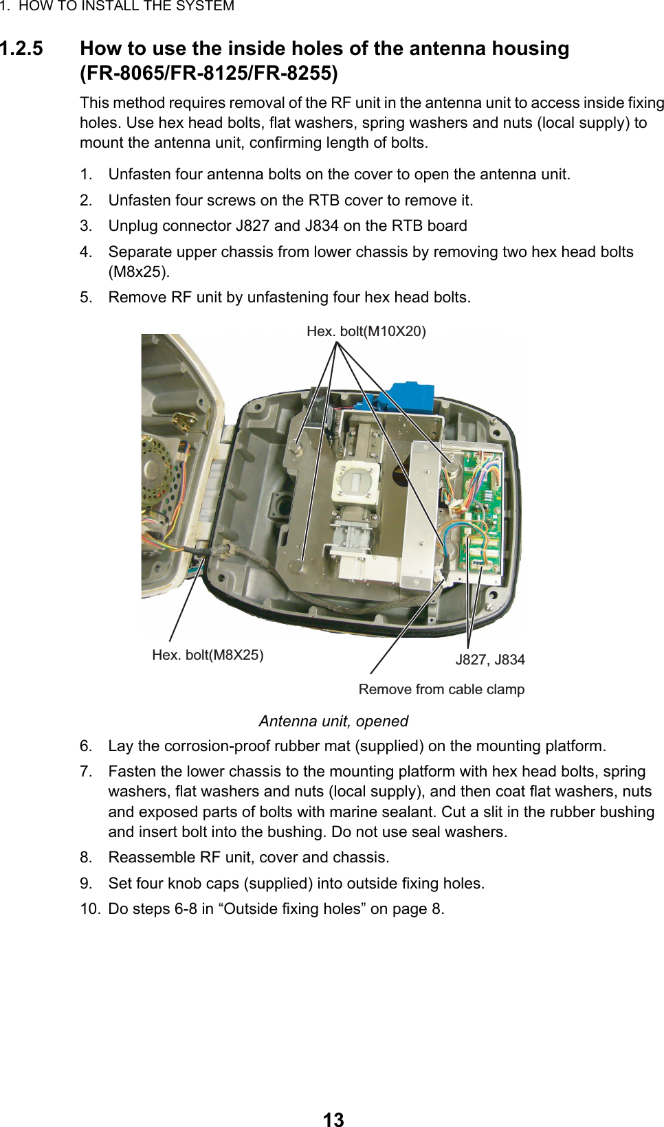
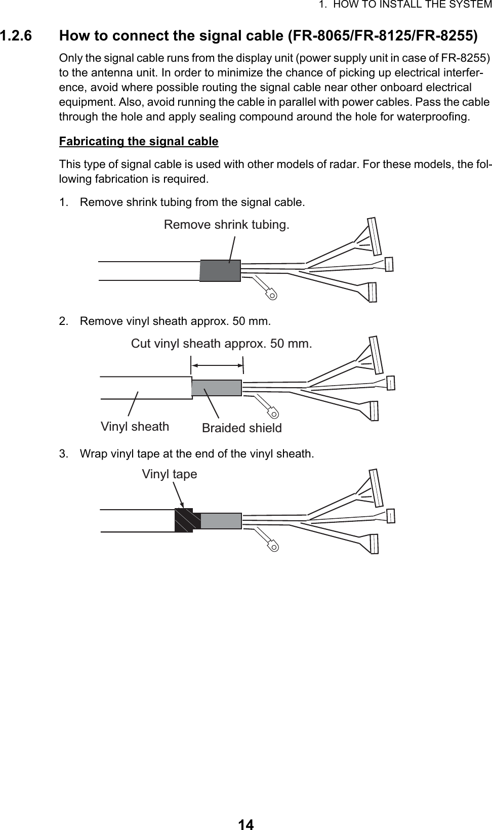
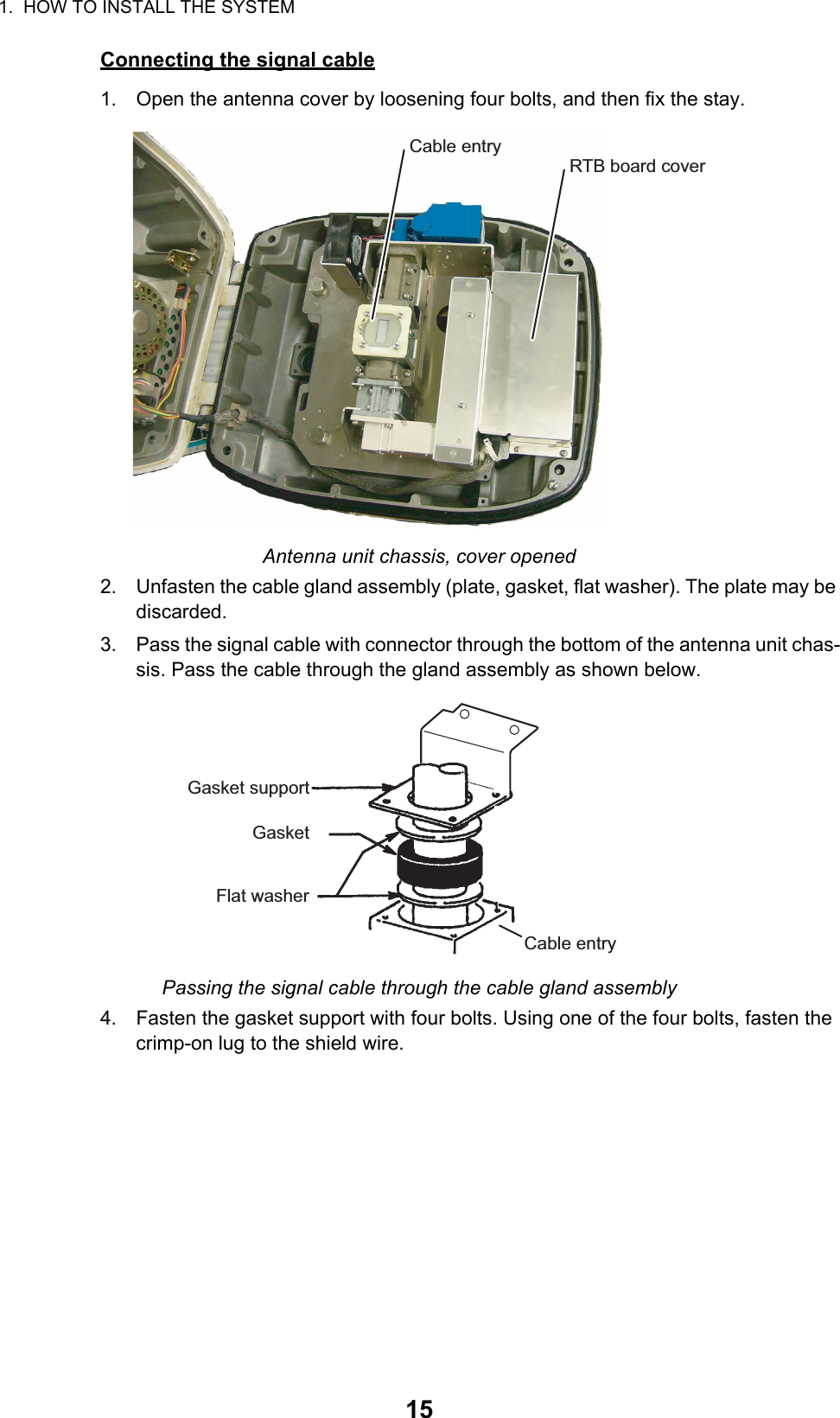
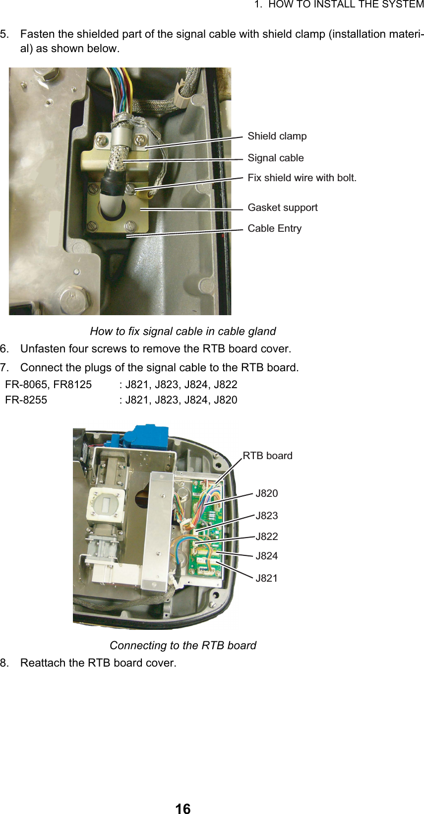
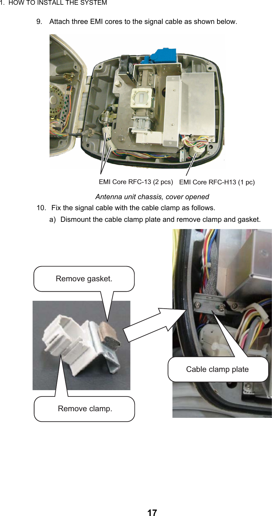
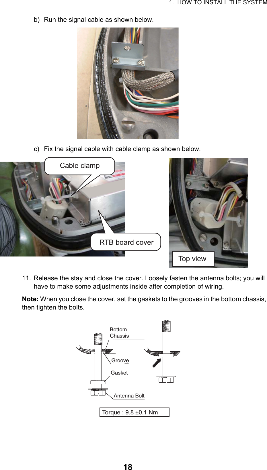
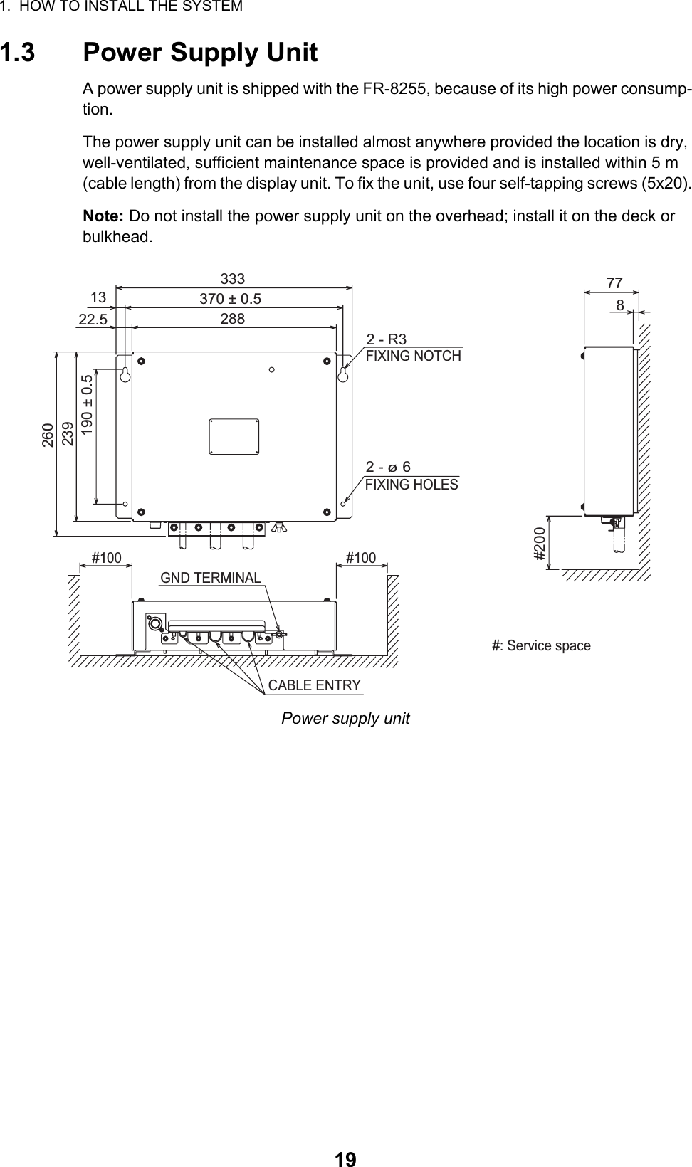
User Manual I Part 1

www.furuno.comAll brand and product names are trademarks, registered trademarks or service marks of their respective holders.Installation ManualMULTI-COLOR LCD RADARModel FR-8045/FR-8065/FR-8125/FR8255SAFETY INSTRUCTIONS ................................................................................................ iSYSTEM CONFIGURATION ........................................................................................... iiEQUIPMENT LISTS........................................................................................................ iii1. HOW TO INSTALL THE SYSTEM ............................................................................. 11.1 Display Unit...........................................................................................................................11.2 Antenna Unit Installation.......................................................................................................51.3 Power Supply Unit ..............................................................................................................192. CABLE CONNECTIONAND WIRING202.1 Standard Connection ..........................................................................................................202.2 Wiring the Power Supply Unit (FR-8255 only) ....................................................................212.3 Data Signals........................................................................................................................232.4 Input/Output Ports...............................................................................................................233. EQUIPMENT SETTINGS.......................................................................................... 253.1 Setting the Language..........................................................................................................253.2 How to Set the Purpose ......................................................................................................263.3 How to Enter Initial Settings................................................................................................274. OPTIONAL EQUIPMENT ......................................................................................... 314.1 ARP Kit ARP-11..................................................................................................................314.2 Connection of Buzzer and/or Remote Display....................................................................33PACKING LISTS ......................................................................................................... A-1OUTLINE DRAWINGS ................................................................................................ D-1INTERCONNECTION DIAGRAMS.............................................................................. S-1
i SAFETY INSTRUCTIONSWARNINGRadio FrequencyRadiation HazardWARNINGCAUTIONCAUTIONCAUTIONCAUTIONWARNINGIndicates a condition that can cause death or serious injury if not avoided.CAUTIONIndicates a condition that can cause minor or moderate injury if not avoided. Warning, Caution Mandatory ActionProhibitive ActionRead these safety instructions before you operate the equipment. Do not open the equipment unless totally familiar with electrical circuits and service manual.Only qualified personnel should work inside the equipment.Wear a safety belt and hard hat when working on the antenna unit.Serious injury or death can result if someone falls from the radar mast.Construct a suitable service platform from which to install the antenna unit.Serious injury or death can result if someone falls from the radar mast.Turn off the power at the mains switchboard before beginning the installation.Fire, electrical shock or serious injury can result if the power is left on or is applied while the equipment is being installed.Ground the equipment to prevent electrical shock and mutual interference. Observe the following compass safe distances to prevent deviation of a magnetic compass.The radar antenna emits electromagnetic radio frequency (RF) energy which can be harmful, particularly to your eyes. Never look directly into the antenna aperture from a close distance while the radar is in operation or expose yourself to the transmitting antenna at a close distance.Distances at which RF radiation levels of 100 W/m2and 10 W/m2 exist are given in the table below.Note: If the antenna unit is installed at a close distance in front of the wheel house, your administration may require halt of transmission within a certain sector of antenna revolution. This is possible - Ask your FURUNO representative or dealer to provide this feature.FR-8065100W/m210W/m2FR-8125FR-8255FR-8045ModelDisplay Unit RDP-154FR-8065 AntennaFR-8125 AntennaFR-8255 AntennaFR-8045 Antenna1.00m1.95m0.65m1.25mPSU-0080.80m 0.50mRSB-0070RSB-0070RSB-0070RSB-0073RSB-0073RSB-00731.90m1.00m1.10m1.85m1.80m0.95m1.20m0.60m0.70m1.25m1.15m0.60mModel Standard SteeringXN-12AXN-13AXN-12AXN-13AXN-12AXN-13AXN-12AXN-13A N/AN/AN/AN/AN/AN/A1.1m1.0m1.9m0.6m0.4m 3.1m4.6m1.7m2.1m1.9m
iiSYSTEM CONFIGURATIONNote 1: 12 VDC cannot be used with this equipment.Note 2: When replacing the antenna, make sure the correct SPU board is used, referring to the table below.Model SPU BoardFR-8045 03P9586BFR-8065/FR-8125/FR-8255 03P9586A24 VDCDisplay unitRDP-154External buzzerEcho sounderGPS navigatorAIS, etc.Remote display: Basic configurationHeading sensorEcho sounderGPS navigatorAIS, etc.: OptionalModel FR-8065Antenna UnitXN-12A-RSB-0070-085AXN-12A-RSB-0073-085AXN-13A-RSB-0070-085AXN-13A-RSB-0073-085AModel FR-8125Antenna UnitXN-12A-RSB-0070-086AXN-12A-RSB-0073-086AXN-13A-RSB-0070-086AXN-13A-RSB-0073-086AModel FR-8255Antenna UnitXN-12A-RSB-0070-087AXN-12A-RSB-0073-087AXN-13A-RSB-0070-087AXN-13A-RSB-0073-087A24 VDCAntenna Power SupplyPSU-008Model FR-8045Antenna UnitXN-12A-RSB-0073-088BXN-13A-RSB-0073-088B
iiiEQUIPMENT LISTSStandard SupplyName Type Code No. Qty CommentsDisplay Unit RDP-154 — 1Antenna UnitRSB-0070/0073-085A —1 Radiator: XN-12A or XN-13ARSB-0070/0073-086A —RSB-0070/0073-087A —RSB-0073-088B —Power Unit PSU-008 — 1 5m Cable For FR-8255Installation MaterialsCP03-30700 000-090-471110m CableFor FR-8065/or FR-8125CP03-30710 000-090-472 15m CableCP03-30720 000-090-473 20m CableCP03-30730 000-090-474 30m CableCP03-30500 000-083-620110m CableFor FR-8255CP03-30510 000-083-621 15m CableCP03-30520 000-083-622 20m CableCP03-30530 000-083-623 30m CableCP03-35600 000-024-717 1 For Display Unit(Screws, Code: 000-162-608-10,5×20 SUS304)CP03-33000 000-014-60415m CableFor FR-8045CP03-33010 000-014-605 10m CableCP03-33020 000-014-606 15m CableCP03-33030 000-014-607 20m CableCP03-33040 000-014-608 30m CableCP03-33801 001-141-670 1 For Antenna Unit:FR-8065/FR-8125/FR-8255CP03-18401 008-503-360 1 For Antenna Unit: FR-8045CP03-22901 008-219-760 1 For RadiatorCP03-30600 000-084-769 1 For PSU-008Spare Parts SP03-17701 001-258-000 1 For Display Unit: Fuse(Code: 000-155-826-10,FGBO 125V 10A PBF)SP03-14501 008-444-420 1 For PSU-008Accessories FP03-12301 001-258-020 1 LCD Cleaning Cloth(Code: 100-360-672-10,19-028-3125-2)
EQUIPMENT LISTSivOptional supplyName Type Code No. Qty CommentsAuto Plotter ARP-11 008-523-050 1External Alarm BuzzerOP03-21 000-030-097 1Signal Cable AssemblyMJ-B24LPF0010-100+R 000-147-880-121 For Remote Display UnitMJ-B24LPF0010-200+R 000-147-881-12MJ-B24LPF0010-300+R 000-147-882-12MJ-A7SPF0007-050C 000-154-028-10 1 For NMEA1/2MJ-A6SPF0007-100C 000-159-695-10 1 For Heading SensorMJ-A10SPFW0001+R 001-074-600-10 1 For Remote Display Unit/External Display splitter cableFlush Mount Kit OP03-228 001-258-030 1
11. HOW TO INSTALL THE SYSTEM1.1 Display UnitSelect a location for the display unit by following the information shown below.•  The unit is waterproof, but FURUNO recommends that you install the display unit in a cabinet.•  Keep the unit away from direct sunlight.•  The temperature and humidity must meet the requirements shown in the equipment specifications.•  Set the unit away from the exhaust pipes and vents.•  The installation location must have enough cool air.•  Install the unit where shock and vibration meet the requirements shown in the equipment specifications. If there is heavy vibration, vertically install the display unit on the hanger.•  Keep the unit away from equipment that creates an electromagnetic field, for exam-ple, motors and generators.•  For maintenance and checking, leave enough space at the sides and rear of the unit, referring to the outline drawing and provide some additional length in cables.•  Follow the recommended compass safe distances shown on page i to prevent the interference to a magnetic compass.NOTICEDo not apply paint, anti-corrosive sealant or contact spray to plastic parts or equipment coating.These items contain products that candamage plastic parts and equipment coating.
1.  HOW TO INSTALL THE SYSTEM21.1.1 How to install the display unitHow to install the display unit on a desktop or overheadFollow the procedure shown below to install the display unit on a desktop or overhead.1. Unfasten the knob bolts and remove the display unit from the hanger.2. Fasten the hanger with four self-tapping screws.3. Screw the knob bolts into the display unit, leaving them slightly loose.4. Connect all necessary cabling.5. Set the display unit in the hanger, then fasten the knob bolts.Note: For overhead installation, make sure the location is strong enough to hold the unit. If necessary, fasten the hanger with the bolts, nuts and washers (local supply).ø5×20 Self-tapping screwsø5×20 Self-tapping screwsHanger rearHanger frontKnobsHard cover
1.  HOW TO INSTALL THE SYSTEM3How to install the display unit in a consoleNote: The unit must be installed in a flat area of the console. Ensure there is ample room behind the unit once installed to allow access for maintenance.Follow the procedure shown below to install the display unit in a console.1. Prepare a hole in the installation location referring to the outline drawing at the back of this manual.2. Unfasten the knob bolts and remove the display unit from the hanger.3. Fit the backing sponges, referring to the diagram below.Note 1: Ensure the backing sponges are used correctly. 1 - Horizontal, 2 - Verti-cal.Note 2: Take care to place the backing sponges around screw holes and ensure there are no gaps between the sponges at their joining points.4. Connect all necessary cables to the unit, making sure to leave enough slack for maintenance and service.5. Insert the unit into the console, making sure that all cabling attached to the unit is not damaged. Ensure the unit is secure before proceeding to the next step.TopBottomUnit base112 2
1.  HOW TO INSTALL THE SYSTEM46. Adjust the flush-mounting fixture by loosening the wingnuts and wingscrews to al-low the bolt free movement. Use the figure below for reference.7. Attach the flush-mounting fixture to the unit referring to the diagram below.8. Fasten the four wingscrews until the footing is flush against the mounting area. See No. 2 in the figure below for reference.9. Tighten the four wingnuts until the unit is firmly secured. See No. 1 in the figure above for reference.Minimal distance between protector and clamp.Flush-mounting fixtureConsoleFlush-mounting fixtureWasherM8×15 Bolt21
1.  HOW TO INSTALL THE SYSTEM51.2 Antenna Unit InstallationHow to select the location for the antenna unit•  The antenna unit is installed either on top of the wheelhouse or a platform on the radar mast. Install the antenna unit where there is a good complete view. Any ob-struction causes blind sectors. For example, a mast with a diameter smaller than the horizontal beamwidth of the radiator causes only a small blind sector. A horizon-tal spreader or crosstrees in the same horizontal plane creates a large obstruction. Install the antenna unit above, or below a horizontal spreader or crosstrees.•  You cannot put the antenna unit where there is a completely clear view in all direc-tions. Make sure you check for blind sectors on the radar screen after you have in-stalled the radar.•  To reduce the electrical interference, do not run the signal cable near other electri-cal equipment. Also do not run the cable in parallel to power cables.•  A magnetic compass gives error if the antenna unit is installed near the magnetic compass. See SAFETY INSTRUCTIONS for the compass safe distances to prevent the interference to a magnetic compass.•  Do not apply paint to the radiator aperture. The radar wave cannot be transmitted if there is paint on the radiator.•  If this radar is installed on a large vessel, follow the points shown below:•  The length of the signal cable between the antenna unit and the display unit is max. 30 m.•  The output from a funnel or exhaust vent decreases aerial performance and hot gases can damage the radiator. The antenna unit must not be installed where the temperature is more than 55°C.•  The antenna unit can be installed on the bridge, a common mast, or the radar mast.(a) On bridge(c) Radar mast(b) Common mast
1.  HOW TO INSTALL THE SYSTEM61.2.1 Installation procedureRefer to the outline drawing at the back of this manual for the dimensions. Make five holes in the platform. Four holes to fasten the antenna unit and one hole for the signal cable.How to fasten the radiator to the chassisSee the packing list at the back of this manual for the installation materials.1. Remove the radiator cap from the radiator bracket.2. Apply marine sealant to the surface of the antenna radiator and the radiator brack-et. See the figure shown below for the location.3. Apply the marine sealant to the threads in the four holes on the antenna radiator.4. Apply the grease to the O-ring and set the O-ring to the radiator bracket.5. Set the antenna radiator on the radiator bracket.6. Apply the marine sealant to the radiator bolts (4 pieces). Fasten the antenna radi-ator to the radiator bracket with the radiator bolts, flat washers and spring wash-ers.RADIATOR BRACKET(top view)Coat hatched area withmarine sealant.10mmFlat washerSpring washerHex head bolt(M8×30)Radiator bracketApply marine sealant to bolts.AntennaradiatorO-ringApply marine sealantto threaded holes
1.  HOW TO INSTALL THE SYSTEM71.2.2 How to install the antenna unitYou can install the antenna unit by one of the two methods shown below.•  Use the outside holes•  Use the inside holesHow to use outside holes of the antenna housingUse the hex head bolts (supplied) to install the antenna unit as shown in the illustration below.1. Put the rubber mat (supplied) on the platform.2. Put the antenna unit on the rubber mat. Align the position of the antenna unit as shown in the illustration below.GroundterminalRubbermatBow markSternBowCAUTIONCAUTIONDo not lift the antenna by the radiator, the radiator may be damaged.Always lift the antenna by the housing.
1.  HOW TO INSTALL THE SYSTEM83. Set four hex head bolts (M12×60, supplied) and seal washers (supplied) from the top of the antenna housing, as shown below.4. Set the flat washers (M12, supplied), spring washers (supplied) and nuts (sup-plied) to the hex head bolts. Tighten by turning the nuts. Do not tighten by turning the hex head bolts, to prevent damage to the seal washers.5. Apply anti-corrosive sealant to the flat washers, spring washers, nuts and visible parts of bolts.6. Prepare the ground point on the platform. Use an M6×25 bolt, nut and flat washer (supplied). The ground point must be within 300 mm from the ground terminal on the antenna unit.7. Run the ground wire (RW-4747, 340 mm, supplied) between the ground terminal and the ground point.8. Apply marine sealant to the ground terminal and ground point as shown below.Hex boltSeal washerFlat washerSpring washerNutSeal washerAntenna chassisCorrosion proof rubber matSeal washerMarine sealantMarine sealantBoltNutORCoat with marine sealant.Hex boltGround wireFlat washerHex nutSpring washerFlat washerMounting PlatformMounting PlatformHex nutHex boltFlat washerSpring washerGround wireMounting PlatformMounting PlatformWeldingGround wireAntenna chassisAntenna chassisFasten ground wire then coat with marine sealant.
1.  HOW TO INSTALL THE SYSTEM91.2.3 How to use the inside holes of the antenna housing (FR-8045)This method requires removal of the RF unit from the antenna unit to access the inside fixing holes. Use four hex head bolts, flat washers, spring washers and nuts (local sup-ply) to install the antenna unit. Check the length of the bolts before you install.Antenna unit chassis, upper chassis separated1. Unfasten four bolts on the cover to open the antenna unit. 2. Disconnect the connectors connected between the upper chassis and the lower chassis.3. Remove two hex head bolts (M8×25) to separate the upper chassis from the lower chassis.4. Loosen four pan head screws to remove the cover from the pc board.5. Remove the connector from the RF unit.6. Loosen four hex head bolts to remove the RF unit.7. Set the corrosion-proof rubber mat (supplied) to the support platform.8. Cut the rubber bushings in the fixing holes and put four bolts from the inside of the lower chassis. Fasten the lower chassis to the support platform with the spring washers, flat washers and nuts (local supply). Apply marine sealant to the flat washers, nuts and visible parts of bolts.9. Assemble the RF unit, cover and chassis.10. Set four caps (supplied) into the outside fixing holes.11. Prepare the ground point on the platform. Use an M6×25 bolt, nut and flat washer (supplied). The ground point must be within 300 mm from the ground terminal on the antenna unit.12. Run the ground wire (RW-4747, 340 mm, supplied) between the ground terminal and the ground point.13. Apply the marine sealant to the ground terminal and ground point. See the illus-tration on page 8 for instructions.RF unitHex head boltM10×20, 4 pcs.Hex head boltM8×25, 2 pcs.Spring WasherM10,  4 pcs.Board coverPan head screwM3×8,  2 pcs.Upper chassisSquare bushingLower chassisPan head screwM3×8,  2 pcs.
1.  HOW TO INSTALL THE SYSTEM101.2.4 How to connect the signal cable (FR-8045)The signal cable runs from the display unit to the antenna unit. To reduce the electrical interference, do not run the signal cable near other electrical equipment. Also do not run the cable in parallel to power cables. Put the cable through the hole and apply sealing compound around the hole for waterproofing.1. Loosen four bolts, open the antenna cover, and set the stay.2. Loosen the cable gland assembly (plate, gasket, flat washer).3. Put the signal cable with the connector through the bottom of the antenna unit chassis. Put the cable through the gland assembly as shown below.4. Fasten the crimp-on lug of the shield wire to one of the four fixing bolts of the cable gland assembly.StayCable gland assy.BoltPlateBolt4 - M4×16GasketFlatwasherShield wire
1.  HOW TO INSTALL THE SYSTEM115. Put the signal cable so that no more than 4 cm of the sheath is visible, as shown in the figure below. Tighten the fixing bolts.6. Loosen four screws in the figure shown below and open the cover.7. Put the signal cable through the cable protector.8. Connect the signal cable to the RTB Board (03P9249). See the interconnection diagram and the figure shown on page 12.SheathCABLE GLANDPlateGasketFlatwasherBoltWithin 4 cmTapingShield wireFour screwsCableprotector
1.  HOW TO INSTALL THE SYSTEM129. Attach three EMI cores to the signal cable as shown below. 10. Fasten the signal cable with the cable clamp.11. Undo the stay and close the cover. Securely fasten the scanner bolts.Note: When you close the cover, set the gaskets to the grooves in the bottom chassis, then tighten the bolts.Run cable along here.Lead incable here.J821  VH9PRTB BoardJ824  NH13PJ823  VH4PClampJ822  VH2PEMI core RFC-13Bottom ChassisGasketGrooveAntenna BoltTorque : 9.8 ±0.1 Nm
1.  HOW TO INSTALL THE SYSTEM131.2.5 How to use the inside holes of the antenna housing(FR-8065/FR-8125/FR-8255)This method requires removal of the RF unit in the antenna unit to access inside fixing holes. Use hex head bolts, flat washers, spring washers and nuts (local supply) to mount the antenna unit, confirming length of bolts.1. Unfasten four antenna bolts on the cover to open the antenna unit.2. Unfasten four screws on the RTB cover to remove it.3. Unplug connector J827 and J834 on the RTB board4. Separate upper chassis from lower chassis by removing two hex head bolts (M8x25).5. Remove RF unit by unfastening four hex head bolts.Antenna unit, opened6. Lay the corrosion-proof rubber mat (supplied) on the mounting platform.7. Fasten the lower chassis to the mounting platform with hex head bolts, spring washers, flat washers and nuts (local supply), and then coat flat washers, nuts and exposed parts of bolts with marine sealant. Cut a slit in the rubber bushing and insert bolt into the bushing. Do not use seal washers.8. Reassemble RF unit, cover and chassis.9. Set four knob caps (supplied) into outside fixing holes.10. Do steps 6-8 in “Outside fixing holes” on page 8.Hex. bolt(M10X20)Hex. bolt(M8X25) J827, J834Remove from cable clamp
1.  HOW TO INSTALL THE SYSTEM141.2.6 How to connect the signal cable (FR-8065/FR-8125/FR-8255)Only the signal cable runs from the display unit (power supply unit in case of FR-8255) to the antenna unit. In order to minimize the chance of picking up electrical interfer-ence, avoid where possible routing the signal cable near other onboard electrical equipment. Also, avoid running the cable in parallel with power cables. Pass the cable through the hole and apply sealing compound around the hole for waterproofing. Fabricating the signal cableThis type of signal cable is used with other models of radar. For these models, the fol-lowing fabrication is required.1. Remove shrink tubing from the signal cable.2. Remove vinyl sheath approx. 50 mm.3. Wrap vinyl tape at the end of the vinyl sheath.Remove shrink tubing.Cut vinyl sheath approx. 50 mm.Braided shieldVinyl sheathVinyl tape
1.  HOW TO INSTALL THE SYSTEM15Connecting the signal cable1. Open the antenna cover by loosening four bolts, and then fix the stay.Antenna unit chassis, cover opened2. Unfasten the cable gland assembly (plate, gasket, flat washer). The plate may be discarded.3. Pass the signal cable with connector through the bottom of the antenna unit chas-sis. Pass the cable through the gland assembly as shown below. Passing the signal cable through the cable gland assembly4. Fasten the gasket support with four bolts. Using one of the four bolts, fasten the crimp-on lug to the shield wire.Cable entryRTB board coverGasket supportGasketFlat washerCable entry
1.  HOW TO INSTALL THE SYSTEM165. Fasten the shielded part of the signal cable with shield clamp (installation materi-al) as shown below.How to fix signal cable in cable gland6. Unfasten four screws to remove the RTB board cover.7. Connect the plugs of the signal cable to the RTB board.Connecting to the RTB board8. Reattach the RTB board cover.FR-8065, FR8125 : J821, J823, J824, J822FR-8255 : J821, J823, J824, J820Shield clampSignal cableFix shield wire with bolt.Gasket supportCable EntryRTB boardJ820J823J822J824J821
1.  HOW TO INSTALL THE SYSTEM179. Attach three EMI cores to the signal cable as shown below.Antenna unit chassis, cover opened10.  Fix the signal cable with the cable clamp as follows.a) Dismount the cable clamp plate and remove clamp and gasket.EMI Core RFC-13 (2 pcs) EMI Core RFC-H13 (1 pc)Remove gasket.Remove clamp.Cable clamp plate
1.  HOW TO INSTALL THE SYSTEM18b) Run the signal cable as shown below.c) Fix the signal cable with cable clamp as shown below.11. Release the stay and close the cover. Loosely fasten the antenna bolts; you will have to make some adjustments inside after completion of wiring.Note: When you close the cover, set the gaskets to the grooves in the bottom chassis, then tighten the bolts.Cable clampRTB board coverTop viewBottom ChassisGasketGrooveAntenna BoltTorque : 9.8 ±0.1 Nm
1.  HOW TO INSTALL THE SYSTEM191.3 Power Supply UnitA power supply unit is shipped with the FR-8255, because of its high power consump-tion.The power supply unit can be installed almost anywhere provided the location is dry, well-ventilated, sufficient maintenance space is provided and is installed within 5 m (cable length) from the display unit. To fix the unit, use four self-tapping screws (5x20).Note: Do not install the power supply unit on the overhead; install it on the deck or bulkhead.Power supply unit#2002 - ø 6 1322.5333370 ± 0.52882 - R3FIXING NOTCHFIXING HOLES190 ± 0.5239260778CABLE ENTRYGND TERMINAL#100 #100#: Service space

Navigation menu