Furuno USA 9ZWWR2100 Dual Polarimetric X-band Weather Radar User Manual
Furuno USA Inc Dual Polarimetric X-band Weather Radar
UserManual.wiki
>
Furuno USA
>
9ZWWR2100 User Manual
>
User Manual
Contents
1.
User Manual
2.
User Manual II
3.
User Manual III
User Manual
Navigation menu
Upload a User Manual
Namespaces
Wiki Guide
HTML
PDF
Info
Views
User Manual
Discussion / Help
Navigation
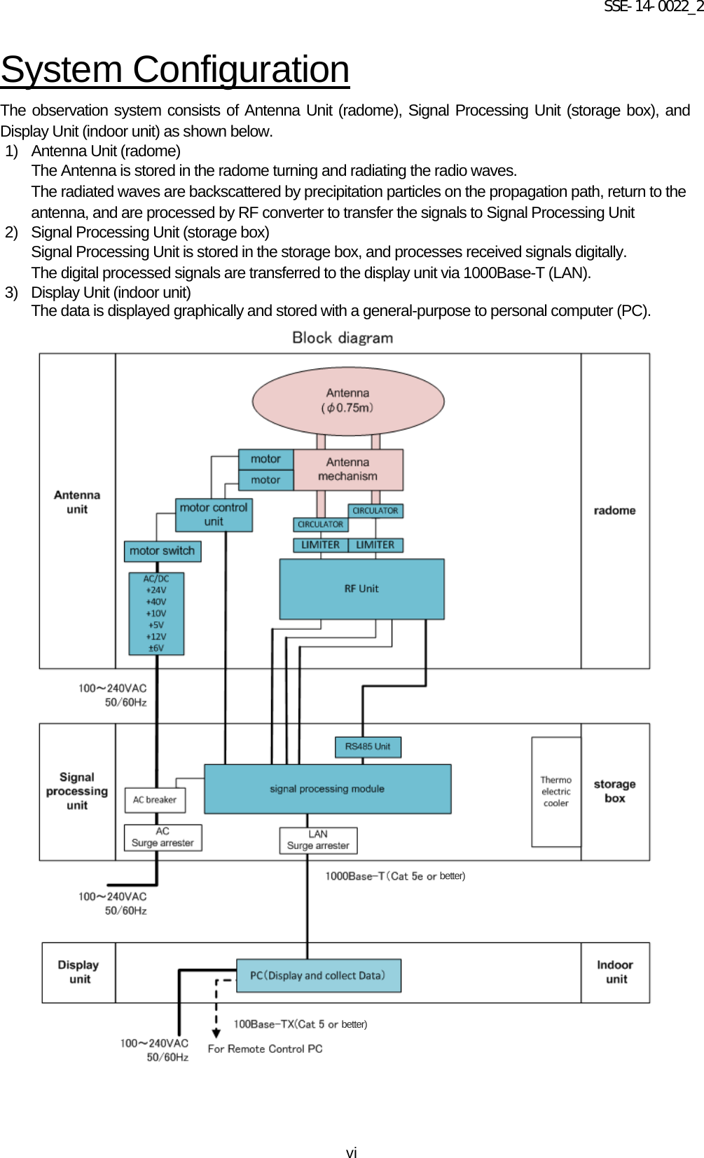
![SSE-14-0022_2 1-2 1.2. Startup the Display Unit (General PC) 1. Install the Display Unit. (1) Connect the LAN cable which connects to external the Signal Processing Unit into the LAN port equipped in the PC. (2) Connect the AC power cable. (3) Connect the LAN cable which connects to external network/PC into a USB-LAN adapter. 2. Turn on the power of the Display Unit (PC). (1) The display software starts automatically. (2) Click [Connect] to start radar operation. (3) Click the [Start emission] to start observation and to display radar images. Display Unit (1) (3) (2)](https://usermanual.wiki/Furuno-USA/9ZWWR2100.User-Manual/User-Guide-2470823-Page-9.png)
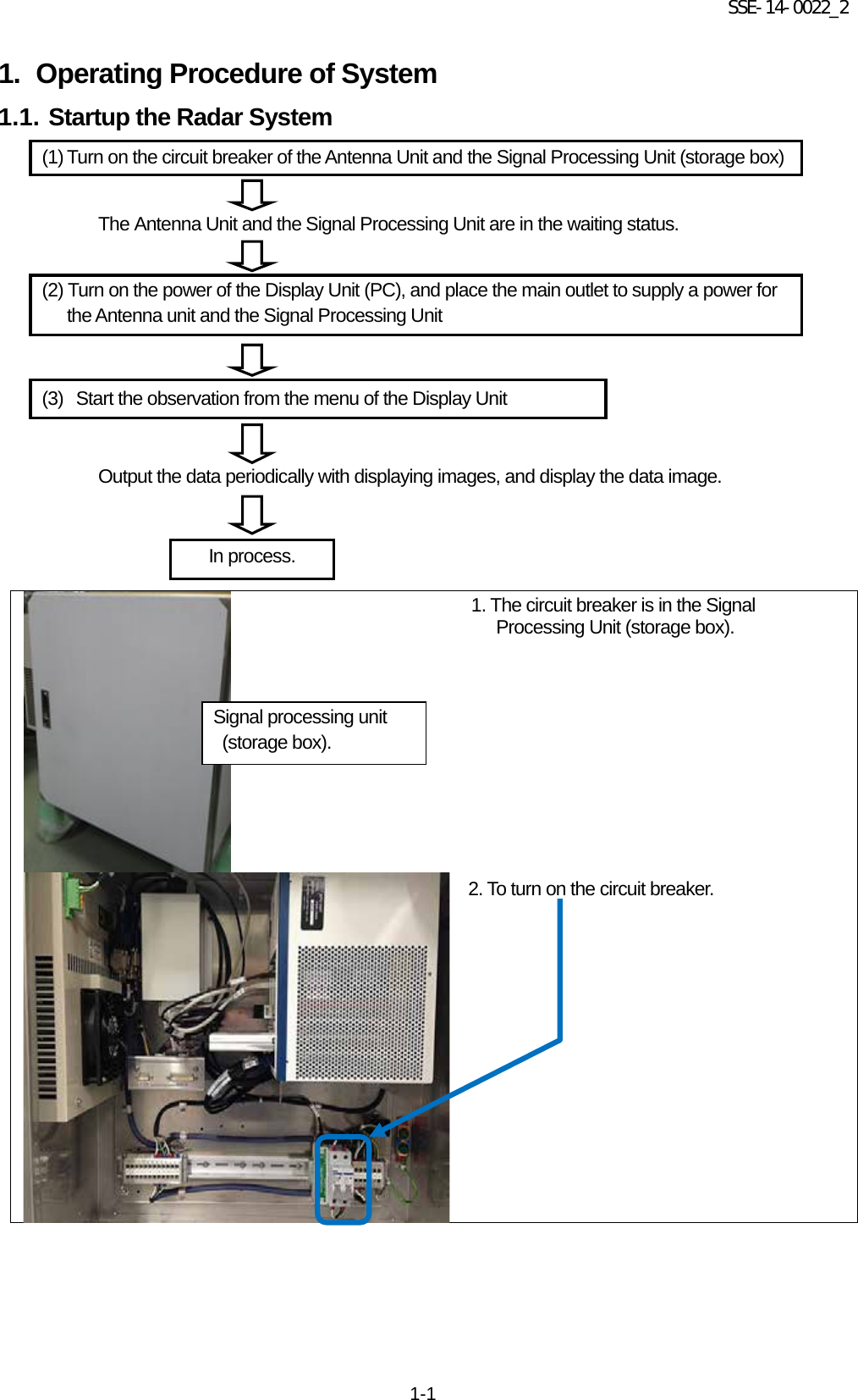
![SSE-14-0022_2 2-2 2.2. Display Unit The display unit receives output data from the Signal Processing Unit (hereinafter called as SPU) and displays the rainfall data in real time. Software name Display software RainMap.exe Specification Function OS: Windows® 8 64bit Professional • Language displayed: English and Japanese (default: English) Change from English to Japanese corresponding to the language setting of Windows® Echo data display: • Observational date and time: Local time display corresponding to the time zone of Windows® • Maximum distance displayed 50 km Display scale 10, 30, 50 [km] Unit displayed (inside: [m]) km • Polar coordinate display (rθ) • Rainfall echo display Display change of rainfall strength (mm/h) or reflection strength (dBZ) • Coloration Maximum 15 colors in table (maximum 16 values including no color) Display of data processed by SPU: • Display of Doppler speed Display Doppler speed data (m/s) Map display: • Local map display: Display BMP map Display of status: Display the setting button and current setting values. • Display the rainfall strength or reflection strength Setting button • Doppler speed display change Change from rainfall echo display to Doppler speed display • Display of radar setting values (Transmission pulse width, PRF) Display of current setting values Setting of radar operation: Conduct the setting to SPU section from the menu and the confirmation. • Removal of interference Obtain a removed echo data that setting to SPU. • Display ON or OFF of topographical echo removal Obtain a removed echo data that setting to SPU. • Transmission mask function Obtain a masked echo data that setting to SPU. • Elevation angle (-2 to 90 degrees) Obtain a specified elevation angle echo data that setting to SPU. • Setting of radar constant (Transmission pulse width, rainfall strength conversion constant B, and β) Obtain a setting echo data that setting to SPU. Data manipulation: • Saving of displayed data Save as a chronological order unit (Time based file name) • Play of displayed data Play from the specification file name. Data output: • Output of data file Output per 1 to 5minutes](https://usermanual.wiki/Furuno-USA/9ZWWR2100.User-Manual/User-Guide-2470823-Page-12.png)
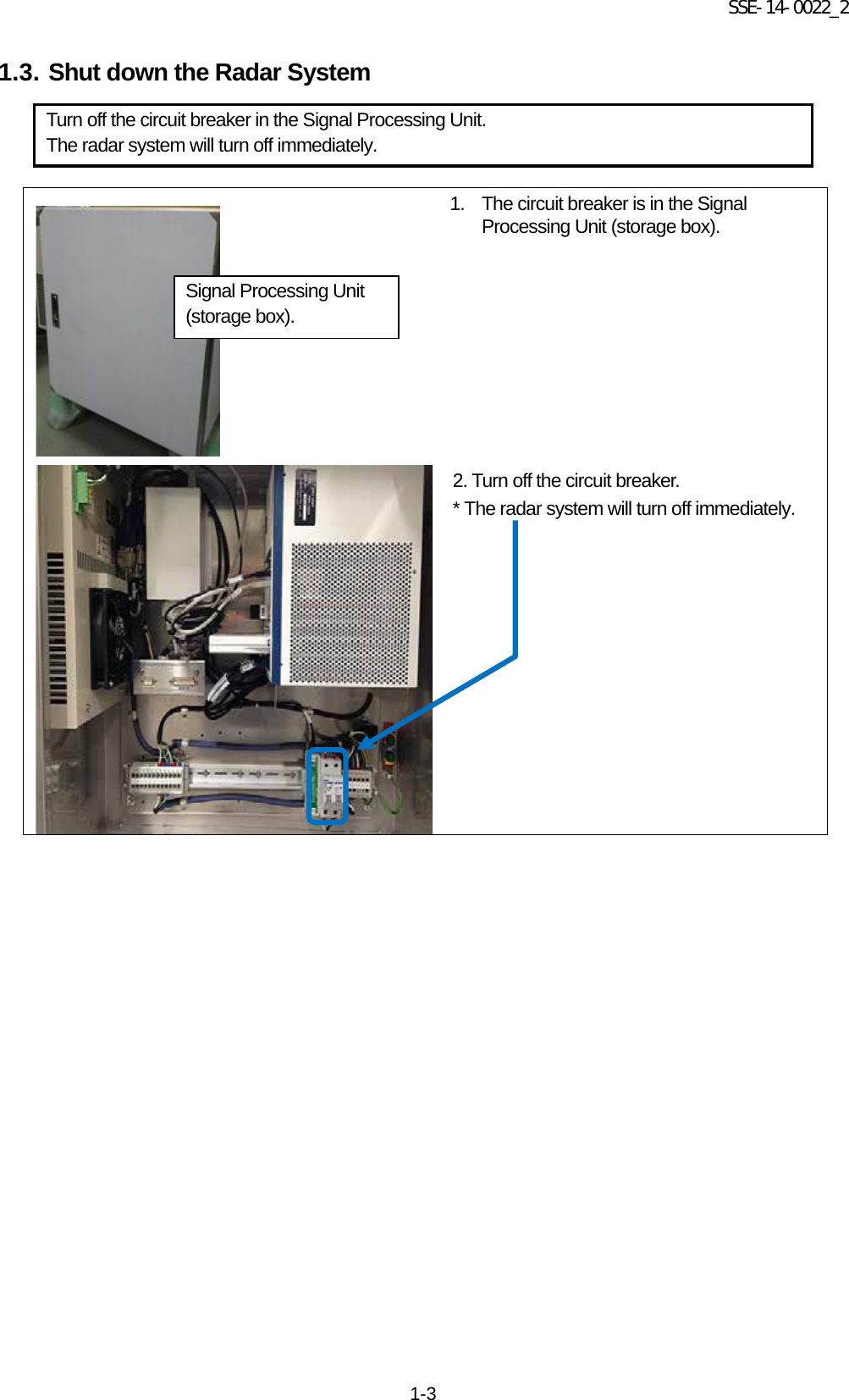
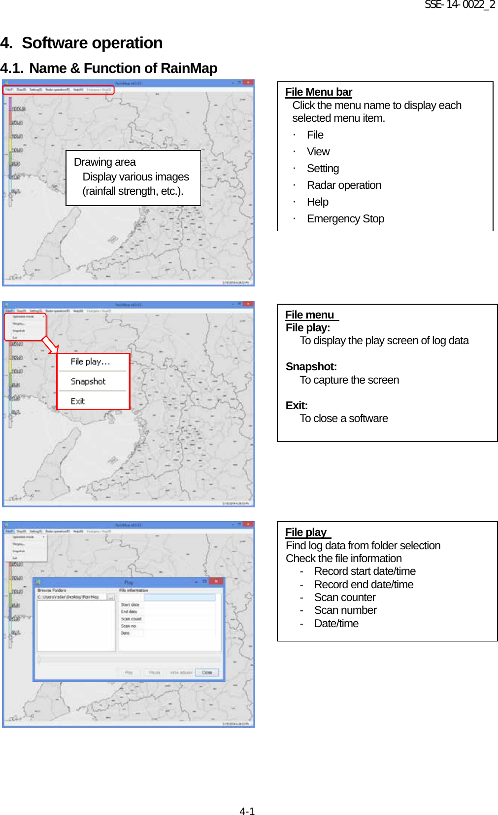
![SSE-14-0022_2 3-1 3. Operating Procedure of Display Unit 3.1. Power up Turn on the power of PC to start Windows® and to display the startup screen. 3.2. Startup screen The following screen will display during startup. 3.3. Power down 1) Shut down the Windows®. Click [Start] -> [Shutdown(U)] -> [OK] 2) Turn off the power of PC. Drawing area Display various images (rainfall strength, etc.).](https://usermanual.wiki/Furuno-USA/9ZWWR2100.User-Manual/User-Guide-2470823-Page-14.png)
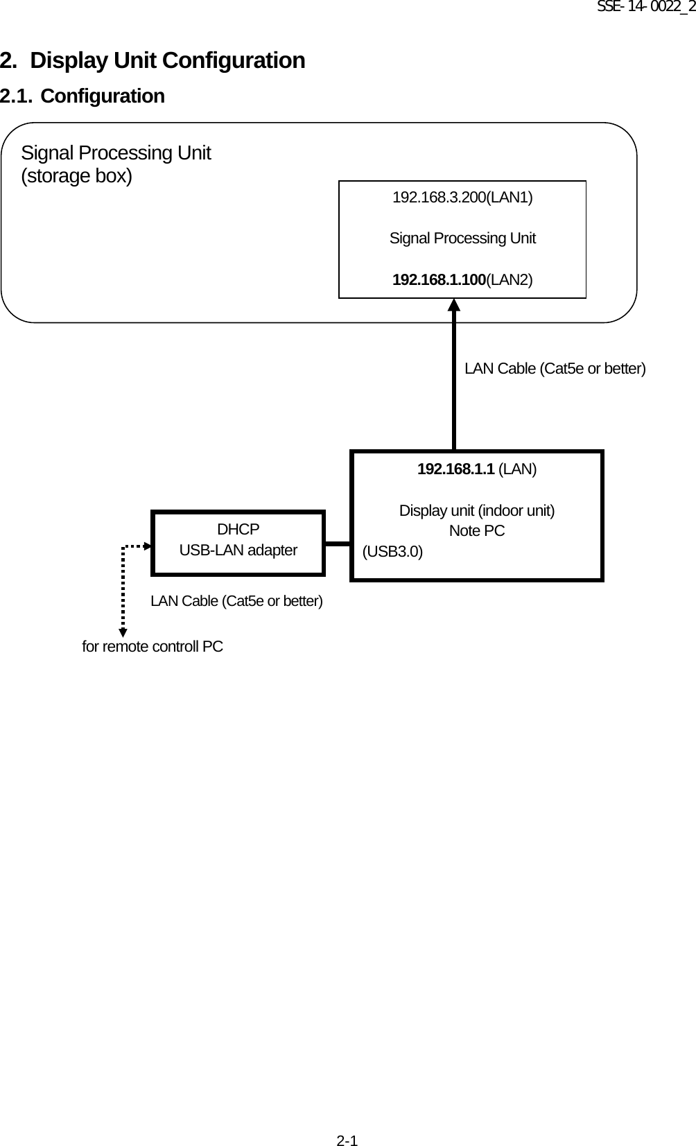
![SSE-14-0022_2 4-3 Acquisition Rec echo: Turn ON or OFF a Log of echo data. Rec file type: To setup a log form of echo data. (dat (idx) / ZIP / dat (idx) + ZIP) Echo folder: To setup a log folder of echo data. Echo zip folder: To setup a log folder of echo zip data file. Rec interval [sec]: To setup a recording interval of echo data. Rec time [hour]: To setup a time of recording echo data. Screen capture: Turn ON or OFF a screen capture. View Range [km]: To setup an indication range. DataType: To setup an indication of the radar parameter. ・ Rainfall intensity: Intensity of rainfall [mm/h] ・ Reflective intensity (H): Reflection factor of the horizontal polarimetric radar [dBz] ・ Reflective intensity (V): Reflection factor of the vertical polarimetric radar [dBz] ・ Doppler speed: Doppler speed [m/s] ・ Zdr[dB]: Radar reflection factor difference ・ Kdp [deg/km]: Propagation phase difference rate of change Ratio of transparency [%]: To setup a Transmittance of the indication echo. Scanning line: Turn ON or OFF a scan line of screen.](https://usermanual.wiki/Furuno-USA/9ZWWR2100.User-Manual/User-Guide-2470823-Page-17.png)
![SSE-14-0022_2 4-4 Antenna Latitude [deg]: To setup a latitude of the installed point. Longitude [deg]: To setup a longitude of the installed point. Altitude [m]: To setup an altitude of the installed point. Image: To setup a filename of map. This program treats as the equidistant cylindrical projection. Left Top Latitude [deg]: To setup a latitude of left top corner of Map Image. Left Top Longitude [deg]: To setup a longitude of left top corner of Map Image. Multiple parameter output Turn ON or OFF an output record of multi-parameter. (*It can setup only when Echo data mode of TRX is selected) Multiple parameter output folder To setup a folder of recording multi-parameter. (*It can setup only when Echo data mode of TRX is selected) Capture folder: To setup a folder of capture. Rec interval [sec]: To setup an interval time of capture Rec CSV: To setup a recording of CSV data. Echo folder (CSV): To setup a folder of CSV data. CSV Rec interval [sec]: To setup an interval time of CSV data. CSV Rec Parameter: To select a weather parameter of recording CSV. ・ Rain [mm/h]: Intensity of rainfall [mm/h] ・ Zhh [dBz]: Reflection factor of the horizontal polarimetric radar [dB] ・ Zvv [dBz]: Reflection factor of the vertical polarimetric radar [dB] ・ DS [m/s]: Doppler speed [m/s] ・ Zdr [dB]: Radar reflection factor difference [dB] ・ Kdp [deg/km]: Propagation phase difference rate of change [deg/km] Right Bottom Latitude [deg]: To setup a latitude of bottom right corner of “Map Image”. Right Bottom Longitude [deg]: To setup a longitude of bottom right corner of “Map Image”.](https://usermanual.wiki/Furuno-USA/9ZWWR2100.User-Manual/User-Guide-2470823-Page-18.png)
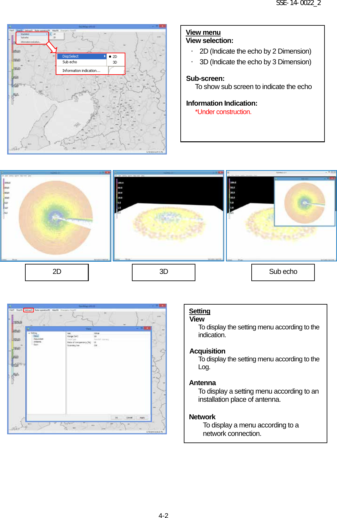
![SSE-14-0022_2 4-5 Scan There are 5 scan patterns that could customize and save a setting. ScanMode: To setup a scan mode of antenna. ・ PPI scan: Equiangular elevation with horizontal rotation mode. It generates 2 dimension data. ・ Spiral scan: The mode to rotate horizontal while shifting elevation continuously, and scans in a spiral. It generates 3 dimension data. ・ Sector RHI scan: The mode to scan elevation direction on special direction area, and generate 3 dimension of rectangular solid angle. ・ HSQ scan: The mode to activate PPI scan while shifting an elevation. It generates 3 dimension data. HSQ Period [min]: To setup an periodic movement of HSQ during HSQ mode. (1(60/(H)) / 2(30/(H)) / 3(20/(H)) / 4(15/(H)) / 5(12/(H)) / 6(10/(H)) / 10(6/(H)) / 12(5/(H))) e.g. HSQ will activate every 2 minutes if select 2/30/(H). (It turns 30 times per hour) PPI elevation [deg]: To setup an angle of antenna’s elevation during PPI mode. PPI azimuth rotation speed [rpm]: To setup the rotation speed of azimuth in rotation per minutes (rpm) Parameters affect only to PPI mode. SPI operation mode: To setup the elevation angle step and azimuth rotation speed. For example, when the setting is shown as below table 1, antenna will rotate at 2.99, 3.99 and 6.99 degrees. Table 1 (Example of SPI (Spiral) operation) Parameter Settings SPI operation mode 2 [deg], 10 [rpm] SPI lower elevation angle 2.99 [deg] SPI horizontal scan rotation 3 SPI lower elevation angel [deg]: To setup an angle of SPI lowest elevation. SPI mode will start from this angle to upper angle. SPI horizontal scan rotation number: To setup a number of rotation in horizontal direction of SPI scan.. It will move upward/downward as setup number while rotating on azimuth direction. SRHI elevation speed [rpm]: To setup elevation speed of SRHI (Sector RHI).](https://usermanual.wiki/Furuno-USA/9ZWWR2100.User-Manual/User-Guide-2470823-Page-19.png)
![SSE-14-0022_2 4-6 Emergency Stop Stop motor To stop motor of radar and TX at once. HSQ elevation movement difference rotation speed [rpm] To setup a rotation speed of elevation direction during elevation change in HSQ (Horizontal Sequence) observation. Rotation speed of elevation direction = [HSQ elevation moving direction of rotation speed] + [HSQ elevation movement difference of rotation speed]. Notice: [HSQ elevation moving direction of rotation speed] ≧ [HSQ elevation movement difference of rotation speed] HSQ measurement azimuth rotation speed [rpm] To setup the azimuth rotation speed at fixed elevation angle. HSQ status delay azimuth revolution [deg] To setup the angle of shifting elevation. HSQ setting elevation 0-31 [deg] To setup the elevation variation. It is possible to setup 32 elevation. SRHI azimuth 0 [deg] To setup the range of azimuth. It will observe RHI in between azimuth 0 to 1 continuously. SRHI azimuth 1 [deg] To setup an angle of azimuth during SRHI observation. SRHI azimuth step [deg] To setup a quantity of antenna rotation while changing an angle of azimuth SRHI elevation 0 [deg] To setup the range of elevation. SRHI will start from elevation 0 to 2. SRHI elevation 1 [deg] To setup an angle of elevation in HSQ (Horizontal Sequence) observation. HSQ elevation movement azimuth rotation speed [rpm] To setup an azimuth rotation speed until the elevation movement in HSQ (Horizontal Sequence) observation Help Version To indicate the version information of software .](https://usermanual.wiki/Furuno-USA/9ZWWR2100.User-Manual/User-Guide-2470823-Page-20.png)
![SSE-14-0022_2 4-7 4.2. Rainfall observation operation 1) Start rainfall observation Click [Connect] from pull-down menu of [Radar Control]. Conduct the setting of elevation angle of antenna, recording of data, and display data. It will indicate [Connect] on the bottom-left of screen when the Signal Processing Unit (SPU) and communication has been connected .](https://usermanual.wiki/Furuno-USA/9ZWWR2100.User-Manual/User-Guide-2470823-Page-21.png)
![SSE-14-0022_2 4-8 Click [TX] from pull-down menu of [Radar operation] . If clicked [No], it will start TX operation without making change. If clicked [Yes], it will initialize the antenna and will indicate a message as below. Radar will start TX operation after initialization. If clicked [Cancel], an operation will be cancelled. Yes Cancel No Do you really want to update the antenna operation setting? There is a difference between antenna setting value of ¥r¥nRainMap and current antenna setting. Yes (Y) No (N) Cancel Warning Information Antenna initialization in progress. Please wait.](https://usermanual.wiki/Furuno-USA/9ZWWR2100.User-Manual/User-Guide-2470823-Page-22.png)
![SSE-14-0022_2 4-9 2) Stop rainfall observation Start the operation of radar, and display the observed information on the screen. The recorded data is saving on a HDD. Click [STBY] to stop the radar operation. Click [Disconnect] to close SPU.](https://usermanual.wiki/Furuno-USA/9ZWWR2100.User-Manual/User-Guide-2470823-Page-23.png)
![SSE-14-0022_2 4-10 4.3. Observation Data operation 1) Start playing the Observation Data 2) Stop playing the Observation Data Click [Stop] to stop playing. Click [File] on File menu bar, and select [File play..] * [File play..] cannot control while accessing with the Signal Processing Unit (SPU). Click [Disconnect] to stop the access. To indicate the play screen. To select a folder which have been saved in [Browse Folders] to play data. To indicate a list of log data. At first, to select a data to play, and then click [Play] to start playing.](https://usermanual.wiki/Furuno-USA/9ZWWR2100.User-Manual/User-Guide-2470823-Page-24.png)
![SSE-14-0022_2 4-11 4.4. Name & Function of RainPlay RainPlay will indicate after selecting [File play] on RainMap. File ○ File play: Select files of log data (*.scn; *rhi) to play (Slide show) on screen ○ Print: ・Main screen: Printout the main screen ・SRHI screen: Printout the SRHI screen ○ Exit: To close a software](https://usermanual.wiki/Furuno-USA/9ZWWR2100.User-Manual/User-Guide-2470823-Page-25.png)
![SSE-14-0022_2 4-12 Setting ○ Scale: Setup a distance of scale into a pop-up window of [Scale] ○ Azimuth offset: Setup a degree of offset into a pop-up window of [Azimuth Offset] Disp ○ Select: Select an indication of data type: ・ Rain: Intensity of rainfall ・ Zhh: Reflection factor of the horizontal polarimetric radar ・ Zvv:Reflection factor of the vertical polarimetric radar ・ DS: Doppler speed ・ Zdr: Radar reflection factor difference ・ Kdp: Propagation phase difference rate of change ・ Φdp: Differential Phase Shift ・ ρhv: Polarimetric Correlation Coefficient ・ W: Spectral Width ○ Ratio of transparency [%]: To setup a Transmittance of the indication echo. ○ Map: Output a map from input file (*.bmp) ○ SRHI screen: SRHI screen will popup on window ○ Clear: Data of RainFile will be cleared on a screen](https://usermanual.wiki/Furuno-USA/9ZWWR2100.User-Manual/User-Guide-2470823-Page-26.png)
![SSE-14-0022_2 4-13 Play ○ Start: To start playing a log data ○ Stop: To stop playing ○ Pause: To pause playing ○ Fast Forward: To fast forward playing ○ Rewind: To rewind playing ○ Time display: Popup a setup windows to setup a time display [between 1000 - 10,000 ms] Snapshot ○ Main screen To copy a main screen and select a place to save a screen file(*.jpg) ○ SRHI screen To copy a SRHI screen and select a place to save a screen file(*.jpg) while Indicating SRHI screen from [Disp]](https://usermanual.wiki/Furuno-USA/9ZWWR2100.User-Manual/User-Guide-2470823-Page-27.png)
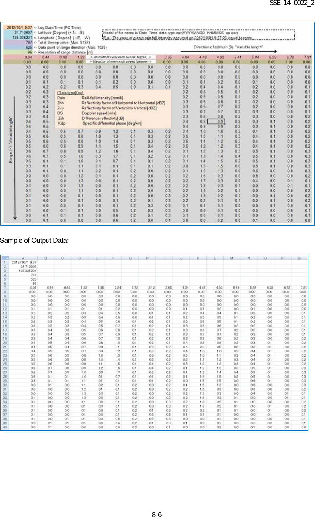
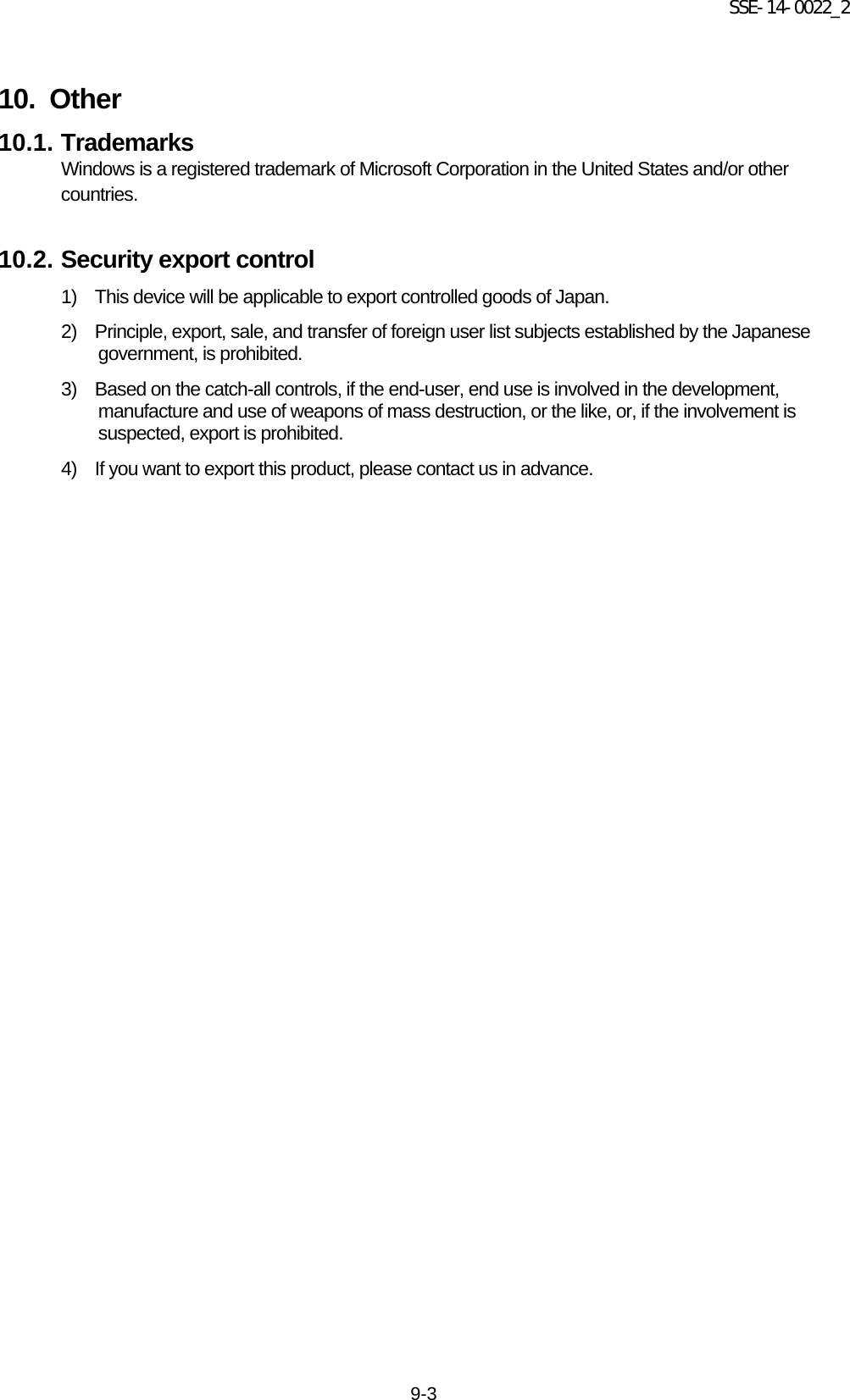
![SSE-14-0022_2 8-5 8.5. Output Data Format 8.5.1. Data file type 1 1) Log unit Write down a file to any folder in a computer in each setting cycle (e.g. 60 sec.) It is possible to set up a log folder. 2) Log file name Output file extension: csv Form: DATE_TIME_DATAKIND.csv (YYYYMMDD_HHMMSS_xx.csv). e.g.) Output the Rainfall strength “01/10/2012 9:37:26” → "20121001_093726_Rain.csv". Output data types are shown below: Rain: Rainfall intensity [mm/h] Zhh: Reflective intensity (Horizontal) [dBZ] Zvv: Reflective intensity (Vertical) [dBZ] DS: Doppler speed [m/s] Zdr: Radar reflection factor difference [dB] Kdp: Propagation phase difference rate of change [deg/km] 3) Data format CSV format: Row Data e.g. 1 Log date (date of PC) 01/10/2012 9:37:26 2 Latitude [deg] (+:N, -:S) 34.713607 deg 3 Longitude [deg] (+:E, -:W) 135.335231 deg 4 The total number of sweeps (MAX 8192) 797 number 5 Data mark of the direction of distance (MAX 1028) 525 point 6 Resolution of the direction of distance [m] 96 m 7 Azimuth direction (θ) [deg] (The angle of azimuth for every sweep) 0.44 deg 8 Elevation direction (θ) [deg] (The angle of elevation for every sweep) 0.00deg 9 Range direction (r) [BIN] to MAX Data mark of the distance direction +7 (Variable length is depends on a number of antenna rotations) row 532 (=525 point + 7row)](https://usermanual.wiki/Furuno-USA/9ZWWR2100.User-Manual/User-Guide-2470823-Page-35.png)
![SSE-14-0022_2 8-7 8.5.2. Data file type 2 1) Log unit Write down a file to any folder in a computer in each scan (one round to azimuth) It is possible to set up a log folder. 2) Log file name File name: Start scenario (year/date/min/sec) + elevation number + modulation system File name extension: scn YYYYMMDD_hhmmss_##_**.scn e.g.) 20130514_123400_01_00.scn Elevation number: If the lowest elevation is 01, it would be 01, 02, 03 …. Modulation system: 00:Pulse modulation, 01:Frequency modulation (pulse compression) 3) Data format Binary format (Byte array: Little endian) Block Item Detail Size [byte] Offset Data type Header Size of header e.g. 56 [Byte] 2 2 unsigned short Version of data format e.g. 001 2 4 unsigned short PC Log time: year e.g. 2013 2 6 unsigned short PC Log time: month e.g. 05 2 8 unsigned short PC Log time: date e.g. 15 2 10 unsigned short PC Log time: hour e.g. 18 2 12 unsigned short PC Log time: minute e.g. 30 2 14 unsigned short PC Log time: second e.g. 00 2 16 unsigned short Latitude: degree e.g. 34 (N. Lat: +, S. Lat:-) 2 18 signed short Latitude: minute e.g. 44 2 20 unsigned short Latitude: second e.g. 59.999 (1000 times level) 2 22 unsigned short Longitude: degree e.g. 135 (E. Lat: +, W. Lat.+) 2 24 signed short Longitude: minute e.g. 21 2 26 unsigned short Longitude: second e.g. 59.999 (1000 times level) 2 28 unsigned short Antenna Altitude (Upper) Range Upper: 0 - 65535 2 30 unsigned short Antenna Altitude (Lower) Range Lower: 0 - 9999 Altitude[cm]=(Upper) x 10000+(Lower) e.g. 123456[cm]=12 x 10000+3456 2 32 unsigned short Antenna rotation speed (azimuth) e.g. 10.0 ([rpm] 10 times level) 2 34 unsigned short PRF1 e.g. 1600.0 ([Hz] 10 times level) 2 36 unsigned short PRF2 e.g. 2000.0 ([Hz] 10 times level) 2 38 unsigned short Noise level (Horizontal polarization) e.g. -62.00 ([dBm] 100 times level) 2 40 signed short Noise level (Horizontal polarization) e.g. -62.00 ([dBm] 100 times level) 2 42 signed short Total number of sweep: L e.g. 720 [qty] 2 44 unsigned short Number of range direction data: M e.g. 300 [qty] 2 46 unsigned short Resolution of range direction e.g. 100.00 ([m] 100 times level) 2 48 unsigned short Constant radar: Mantissa (Horizontal polarization) Range: -999999999 - 999999999 4 52 signed long](https://usermanual.wiki/Furuno-USA/9ZWWR2100.User-Manual/User-Guide-2470823-Page-37.png)
![SSE-14-0022_2 8-8 Header Constant radar: Characteristic (Horizontal polarization) Range: Characteristic:-32768 - 32767 Constant=(Mantissa) x 10^(Characteristic) e.g. 9.876E-9=9876 x 10^-12 2 54 signed short Constant radar: Mantissa (Vertical polarization) Same as above (Same as horizontal polarization) 4 58 signed long Constant radar: Characteristic (Vertical polarization) 2 60 signed short Observation angularity information Information ID e.g. 6 2 62 unsigned short Azimuth Range: 0 - 359.99 [deg] 100 times level North: 0 deg 2 64 unsigned short Elevation Range: -3.00 - 180.00 [deg] 100 times level Horizontal: 0deg, Elevation: +, Dip: - 2 66 signed short Observed data Information ID e.g. 4802 2 68 unsigned short Rain(Rainfall intensity) Range: 0 - 65535 Calculation formula N is a recording level. Rain[mm/h]=(N-32768)/100 Rain Range: -327.67 - 327.67mm/h Resolution: 0.01mm/h N=0 is invalid 2 x Range direction data mark unsigned short Zhh(Reflective intensity Horizontal polarization) Range: 0 - 65535 Calculation formula N is a recording level. Zhh[dBZ]=(N-32768)/100 Zhh Range: -327.67 - 327.67dBz Resolution: 0.01dBz N=0 is invalid 2 x Range direction data mark unsigned short V(Doppler speed) Range: 0 - 65535 Calculation formula N is a recording level. V[m/s]=(N-32768)/100 V Range: -327.67 - 327.67m/s Resolution: 0.01m/s N=0 is invalid 2 x Range direction data mark unsigned short Zdr(Radar reflection factor difference) Range:0 - 65535 Calculation formula N is a recording level. Zdr[dB]=(N-32768)/100 Zdr Range: -327.67 - 327.67dB Resolution: 0.01dB N=0 is invalid 2 x Range direction data mark unsigned short Kdp(Propagation phase difference rate of change) Range: 0 - 65535 Calculation formula N is a recording level. Kdp[deg/km]=(N-32768)/100 Zdp Range: -327.67 - 327.67deg/km Resolution: 0.01deg/km N=0 is invalid 2 x Range direction data mark unsigned short](https://usermanual.wiki/Furuno-USA/9ZWWR2100.User-Manual/User-Guide-2470823-Page-38.png)
![SSE-14-0022_2 8-9 Observed data φdp(Differential phase shift) Range: 0 - 65535 Calculation formula N is a recording level. φdp [deg]=360*(N-1)/65535 φdp Range: 0.0 - 359.9945deg Resolution: 0.0055deg N=0 is invalid 2 x Range direction data mark unsigned short ρhv(Correlation coefficient between horizontally and vertically polarized echoes) Range: 0 - 65535 Calculation formula N is a recording level. ρhv[no unit]=2 x (N-1)/65534 ρhv Range:0.0 - 2.0 Resolution: 0.0000030 N=0 is invalid 2 x Range direction data mark unsigned short W(Doppler speed width) Range: 0 - 65535 Calculation formula N is a recording level. W[m/s]=(N-1)/100 W Range: 0.00 - 655.34m/s Resolution: 0.01m/s N=0 is invalid 2 x Range direction data mark unsigned short Observation angularity information sweep 1 Range direction data 1 Observation data sweep 1 Range direction data 1 | | | | sweep 1 Range direction data M | sweep 1 Range direction data M | sweep 2 Range direction data 1 | sweep 2 Range direction data 1 | | | | sweep 2 Range direction data M | sweep 2 Range direction data M | Sweep L Range direction data 1 | Sweep L Range direction data 1 | | | | Sweep L Range direction data M | Sweep L Range direction data M 8.5.3. Data size 1) Every scan quantity (one round to azimuth direction) Header Observation angularity information Observation data Range direction data Total sweep Quantity of every scan 60 + ((6 + 2) + (16 x e.g. 300)) x e.g. 720 = 3,461,820 byte 2) Quantity in every hour 3,461,820 byte x 3600 sec. / 6 sec. = approx. 2.1GB(2,077,092,000) 3) Quantity in 30 days 2,077,092,000 byte x 31 days x 24 hrs. = approx. 1.55TB](https://usermanual.wiki/Furuno-USA/9ZWWR2100.User-Manual/User-Guide-2470823-Page-39.png)
![SSE-14-0022_2 9-1 9. Menu Tree RainMap Menu [File] Menu [File Play.] Menu [Snapshot] Menu [Exit] Menu [Disp] Menu [Disp select] Menu [2D] Menu [3D] Menu [Sub echo] Menu [Information Indication] Menu [Setting] Input [View] Input [Acquisition] Input [Antenna] Input [Scan] Menu [Radar Operation] Menu [Connect] Menu [Disconnect] Menu [TX] Menu [STBY] Menu [Help] Menu [Version] Menu [Emergency Stop] Menu [Stop motor]](https://usermanual.wiki/Furuno-USA/9ZWWR2100.User-Manual/User-Guide-2470823-Page-40.png)
![SSE-14-0022_2 9-2 RainPlay Menu [File] Menu [File Play] Menu [Print] Menu [Main screen] Menu [SRHI screen] Menu [Exit] Menu [Setting] Input [Scale] Input [Azimuth Offset] Menu [Disp] Menu [Select] Menu [View] Input [Rain] Input [Zhh] Input [V] Input [Zdr] Input [Kdp] Input [φdp] Input [phv] Input [W] Menu [Transparency] Input [0%] Input [25%] Input [50%] Input [75%] Input [100%] Menu [Map] Menu [SRHI screen] Menu [Clear] Menu [Play] Menu [Start] Menu [Stop] Menu [Pause] Menu [Fast Forward] Menu [Rewind] Menu [Time Display] Menu [Print screen ] Menu [Main screen] Menu [SRHI screen]](https://usermanual.wiki/Furuno-USA/9ZWWR2100.User-Manual/User-Guide-2470823-Page-41.png)
![SSE-14-0022_2 12-1 12. Option 12.1. Construction equipments (Option) Items Descriptions Qty M10x35 Hexagon Bolt Material : SUS304 (Fix for up/down parts of radome) 12 M10 Spring Washers Material : SUS304 (Fix for up/down parts of radome) 12 M10 Flat Washers Material : SUS304 (Fix for up/down parts of radome) 12 M12x40 Hexagon Bolt Material : SUS304 (Fix for radome and mount plate) 5 M12 Spring Washers Material : SUS304 (Fix for radome and mount plate) 5 M12 Flat washers Material : SUS304 (Fix for radome and mount plate) 5 FV2-M4 Round Crimping Terminal For electric cables 6 Putty for pipe Non-hardening, Electric insulation qs Multi Plug Outlet Power strip (3-core) 4-Outlets minimum w/ surge protector 1 Heavy Duty Cable Tie (2 types) Nylon 6/6 w/ weather resistance 140mm, 300mm 100 M10 Anchor Bolt Fixed for storage box 4 Earth wire 2sq green To protection against electric shock 1 Notice: Please refer to attached documents of UPS, Router, and other equipments separately. 12.2. Construction tools (Reference parts) Items Descriptions SMA Torque wrench 74Z-0-0-21 SMA connector conclusion Substitute: Caliber 5/16 inch or 8mm wrench Socket Wrench (4 types) M8 (13mm), M10 (17mm), M12 (19 mm)、M16 (24mm) hexagon bolt (Substitute: Monkey wrench) Hexagon Wrench (3 types of Ball-point) M3 (2.5mm), M4 (3mm), M5 (4mm) Bolt with Hexagon hole [+] Driver No.1 Dsub-9pin [+] Driver No.2 M3, M4, M5, Dsub-25pin, for Electric Filter [+] Driver No.2 (Long type) Length 30cm minimum fixed for PXI [-] Driver M8 Multiuse Box Driver (2 types) 5mm, 5.5mm fixed for Dsub connector Flat Ratchet (3 types) M10 (17mm), M12 (19mm), M16 (24mm) Nipper For wiring work Wire Strippers For wiring work Electrical workers knives For wiring work Crimped Terminal tool 1.25sq Power cable (M4), GND wire (M8) for wiring work Tape Measures (5m minimum) Measure length of outdoor power cable and LAN cable Self-fusing Tape (Black) Fit Tape insulation / protect (Length 10m) Electrical Tape (Black) Heat & Fire proof (L19m x W20mm x D0.18mm) Curing Tape Multiuse Chemiseal S-8400W Aluminum Tube 50G Silicone grease Temperature range -30 to +200°C Safety belt For high place work](https://usermanual.wiki/Furuno-USA/9ZWWR2100.User-Manual/User-Guide-2470823-Page-45.png)