Furuno USA 9ZWWR2100 Dual Polarimetric X-band Weather Radar User Manual II
Furuno USA Inc Dual Polarimetric X-band Weather Radar II
UserManual.wiki
>
Furuno USA
>
9ZWWR2100 User Manual
>
User Manual II
Contents
1.
User Manual
2.
User Manual II
3.
User Manual III
User Manual II
Navigation menu
Upload a User Manual
Namespaces
Wiki Guide
HTML
PDF
Info
Views
User Manual
Discussion / Help
Navigation
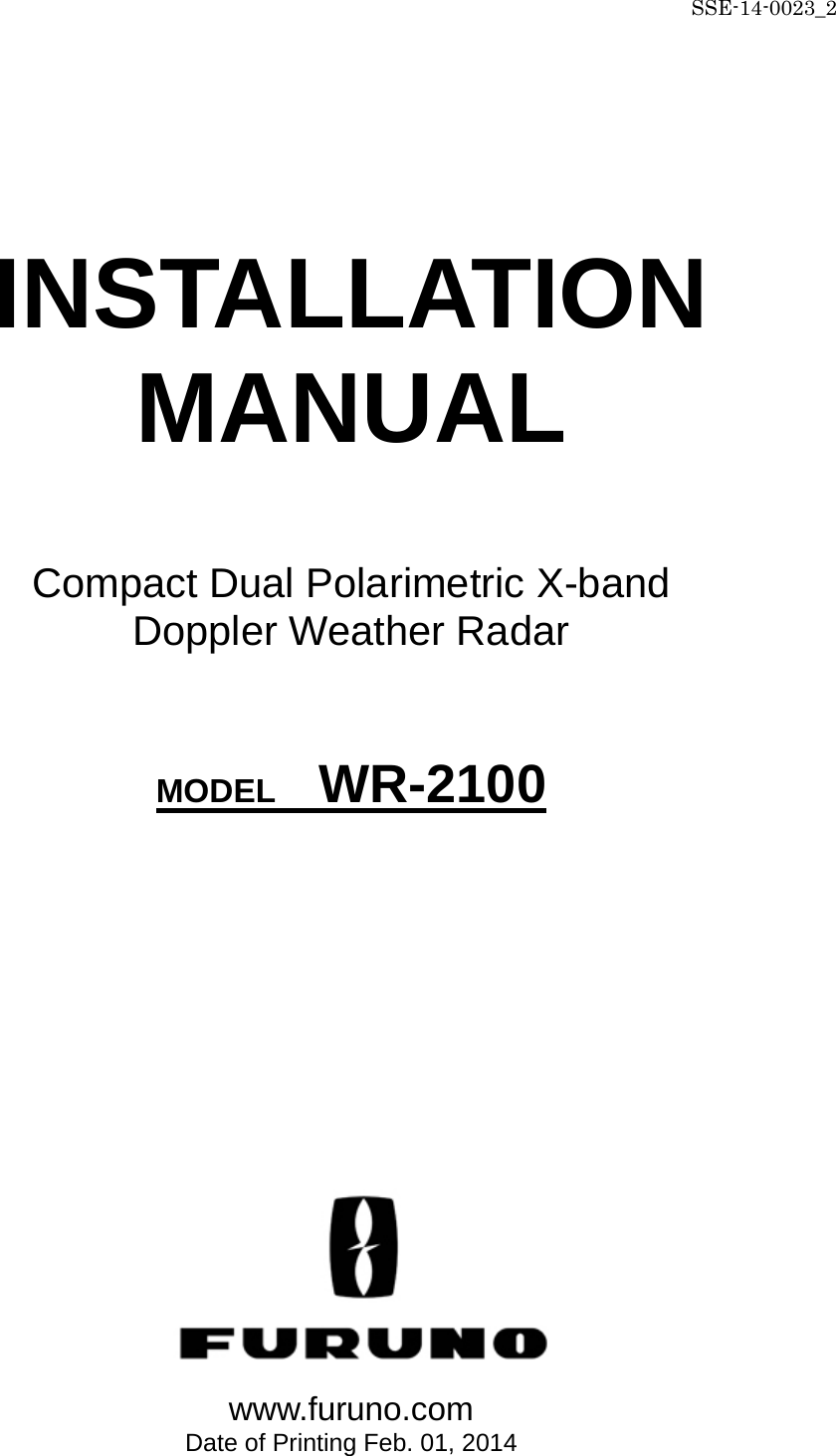

![SSE-14-0023_2 4-2 4.5. Construction tools Items Descriptions SMA Torque wrench 74Z-0-0-21 SMA connector conclusion Substitute : Caliber 5/16 inch or 8mm wrench Socket Wrench (4 types) M8 (13mm), M10 (17mm), M12 (19 mm)、M16 (24mm) hexagon bolt (Substitute : Monkey wrench) Hexagon Wrench (3 types of Ball-point) M3 (2.5mm), M4 (3mm), M5 (4mm) Bolt with Hexagon hole [+] Driver No.1 Dsub-9pin [+] Driver No.2 M3, M4, M5, Dsub-25pin, for Electric Filter [+] Driver No.2 (Long type) Length 30cm minimum fixed for PXI [-] Driver M8 Multiuse Box Driver (2 types) 5mm, 5.5mm fixed for Dsub connector Flat Ratchet (3 types) M10 (17mm), M12 (19mm), M16 (24mm) Nipper For wiring work Wire Strippers For wiring work Electrical workers knives For wiring work Crimped Terminal tool 1.25sq Power cable (M4), GND wire (M8) for wiring work Tape Measures (5m minimum) Measure length of outdoor power cable and LAN cable Self-fusing Tape (Black) Fit Tape insulation / protect (Length 10m) Electrical Tape (Black) Heat & Fire proof (L19m x W20mm x D0.18mm) Curing Tape Multiuse Chemiseal S-8400W Aluminum Tube 50G Silicone grease Temperature range -30 to +200 °C Safety belt For high place work 4.6. Measurement Items Descriptions Remarks Digital Multi Meter Voltage AC : 85 to 240 V DC : 1 to 50V Current AC : 1 to 10 A DC : 1mA to 1A Resistor 0.1 to 10M ohm Tester Lead Cables Angle Meter Measurement range : ≧ 45deg Accuracy : within ±0.2deg Zero adjustment vertical angle of RADAR 4.7. LAN equipment 1) Use Cat5e (or better grade) of 1000Base-Tx LAN cable for transferring the data from display unit to output equipment. 2) Be prepared High speed broadband (approx.100Mbps) for using remote maintenance. *Low speed broadband may cause slow access on remote to support a system.](https://usermanual.wiki/Furuno-USA/9ZWWR2100.User-Manual-II/User-Guide-2470824-Page-14.png)
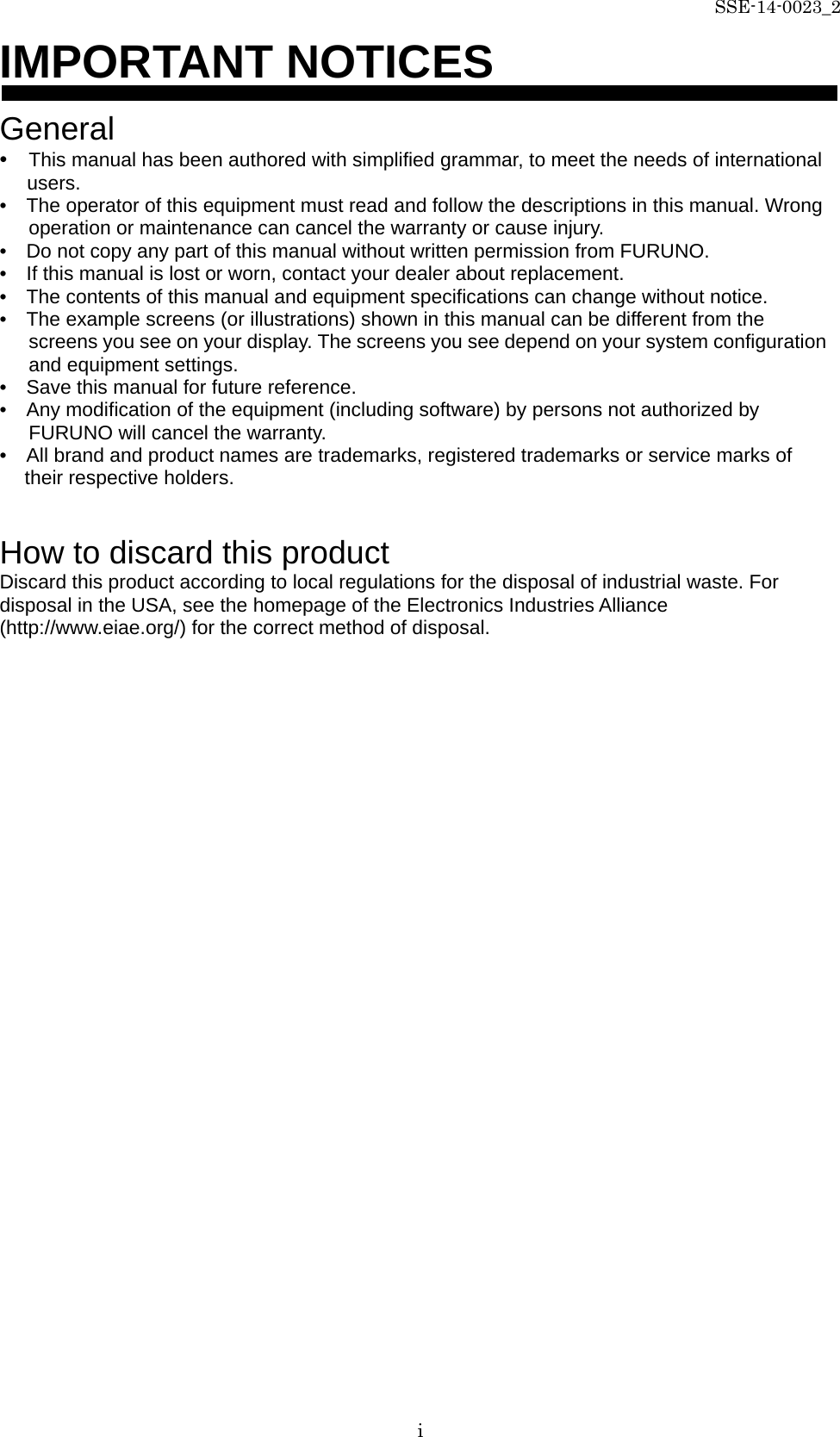
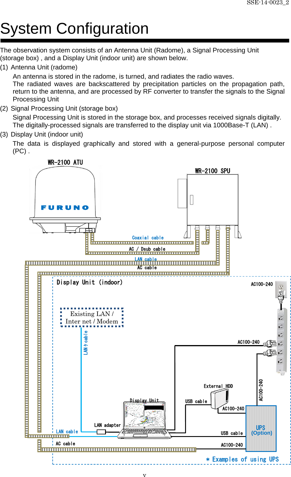
![SSE-14-0023_2 6-1 6. Construction All installation places will be considered for installing PC, cables, pipes, and mount kit during the environmental survey. 6.1. Mount kit <Case 1> The case of not able to make a hole on pedestal. <Case 2> The way of using steel frames. Open more than 100mm of space. Adjust the hole (10 holes [ ] ) with the mount plate and the steel frames. Make holes to the steel frames with 20Φ for M16 hexagon bolt to join with the mount plate.](https://usermanual.wiki/Furuno-USA/9ZWWR2100.User-Manual-II/User-Guide-2470824-Page-16.png)
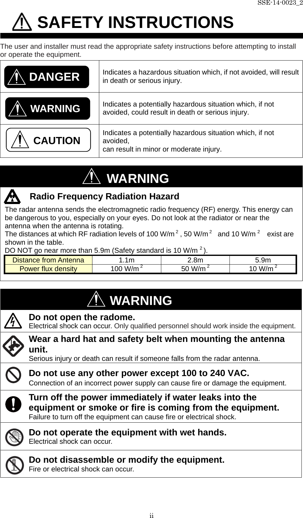
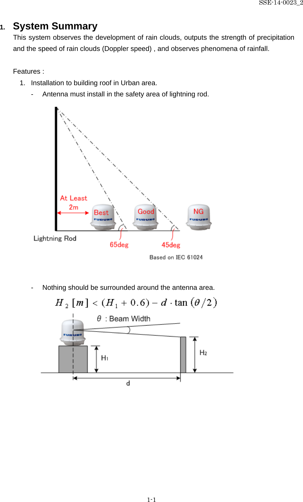
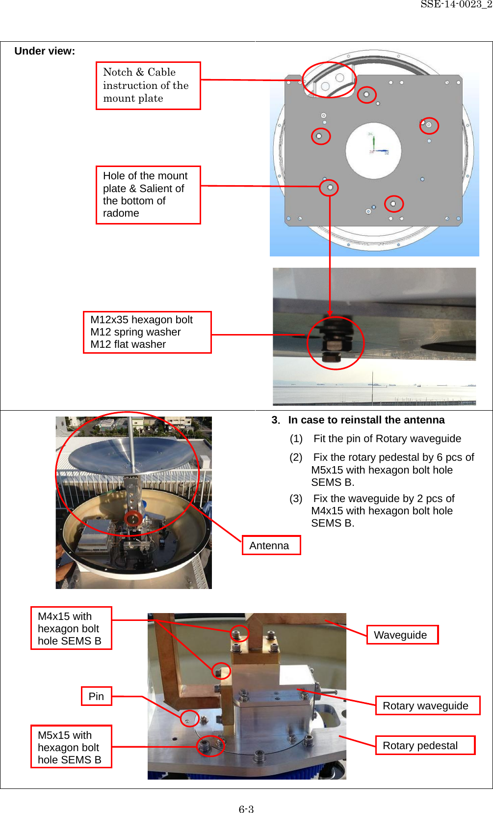
![SSE-14-0023_2 6-2 <Case 3> The way to put the mount plate directly on to a wooden pedestal. 6.2. Antenna Unit (Radome) 1.Set up the base. 2.Set the bottom of radome to the base. (1) Adjust the cable introduction of under radome to notch of the base. (2) To fit the bottom of radome with five salient into the base hole (3) To fix 5 pcs of M12x35 hexagon bolt (with M12 spring washer, M12 flat washer) to join the base and radome. The mount plate (900mm×800mm×10mm) Make 10 holes [ ] to a wooden pedestal with 20Φ for M16 hexagon bolt to join with the mount plate. In this case, it may need to make 2 big holes for Protecting Tube to get through. Bottom of radome](https://usermanual.wiki/Furuno-USA/9ZWWR2100.User-Manual-II/User-Guide-2470824-Page-17.png)
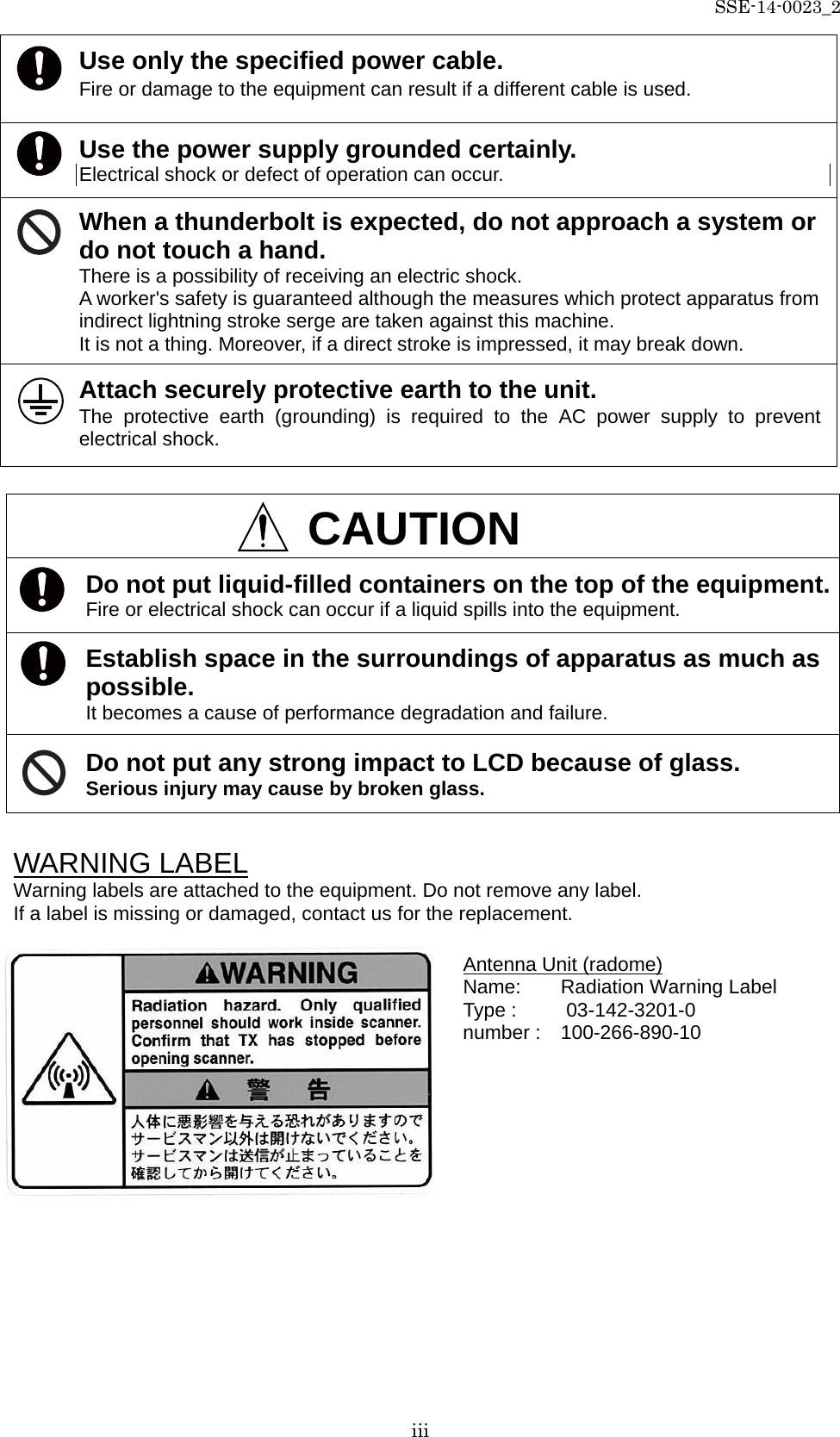
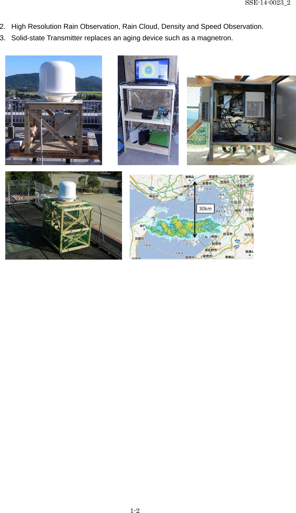
![SSE-14-0023_2 6-9 6.Make the power plug (beside Display Unit) - Make 3 pin earthed power plug that running through the SPU. - Place an outlet 7. Activation test - Turn on the power breaker. - Follow the instruction to test it. 8. Cooler setting Setup temperature of cooler to 25 Celsius degrees . (1) Press [Set] button to indicate a temperature of setting. (2) Press [Up], [Down] button to setup a temperature to 25 Celsius degree. (3) Press [Set] button to indicate a current temperature. 9. Measure the AC power - Measure the value of AC power that comes into SPU from the main outlet. - Reference range: -10% to +10% 10. Connect LAN cable to connect with display unit. Control panel Display (Temperature will indicate when power up) Setup button Alarm lamp (RED) Lamp ON: Alarm occurs Lamp Blink: Forced heater ON Down button Up button Alarm lamp (GREEN) Lamp ON: Cooler ON Lamp OFF: Cooler OFF 0.5S Lamp Blink: Forced cooler ON 1.0S Lamp Blink: Heater ON Air inlet Terminal unit Air inlet Air fan and outlet 25](https://usermanual.wiki/Furuno-USA/9ZWWR2100.User-Manual-II/User-Guide-2470824-Page-24.png)
![SSE-14-0023_2 8-1 8. Install TeamViewer (Remote control management tool) 1. Download the software of TeamViewer Host (For remote server) from the following web site: http : //www.teamviewer.com/ja/download/windows.aspx 2. Double click “TeamViewer_Host_Setup.exe” to install the software. 3. After installed software, please inform “Your ID” to the headquarter of Furuno who is in charge. 4. Use other PC to confirm remote access by TeamViewer. (6) “Your ID” will be issued automatically. (* Remember this ID) And then click [OK] (1) Double click the icon (2) Click [Next] (3) Select “company / commercial use”, and then click [Next] (4) Check on “License Agreement”, and then click [Next] (5) Make password and computer name Password: rmsrms (enter this password) Computer name: Enter location’s name And then click [Exit] 123 456 789](https://usermanual.wiki/Furuno-USA/9ZWWR2100.User-Manual-II/User-Guide-2470824-Page-28.png)
![SSE-14-0023_2 8-2 5. The following instruction is to setup security on TeamViewer Host if necessary. * Please confirm to a customer and Furuno Headquarter before setup. (1) Right click to the icon of TeamViewer in task bar. (2) [TeamViewer options] will indicate a Popup menu on a screen after clicked [Option] from dropdown list of TeamViewer. (3) Click [Security] on the right list of [TeamViewer options] (4) Click [Configure] of [Black and whitelist] under a menu of [Rules for connections to this computer]. (5) It could register an opponent ID on the list to whether [Deny access for the following IDs and partners] or [Allow access only for the following IDs and partners] from Popup menu of [Black and whitelist].](https://usermanual.wiki/Furuno-USA/9ZWWR2100.User-Manual-II/User-Guide-2470824-Page-29.png)