Furuno USA 9ZWWR2100 Dual Polarimetric X-band Weather Radar User Manual II
Furuno USA Inc Dual Polarimetric X-band Weather Radar II
Contents
- 1. User Manual
- 2. User Manual II
- 3. User Manual III
User Manual II

SSE-14-0023_2
INSTALLATION
MANUAL
Compact Dual Polarimetric X-band
Doppler Weather Radar
MODEL WR-2100
www.furuno.com
Date of Printing Feb. 01, 2014
SSE-14-0023_2
FURUNO ELECTRIC CO.,LTD.
9-52 Ashihara-cho,
Nishinomiya, 662-8580, Japan
Printed in Japan
( TAHA ) WR-2100
・FURUNO Authorized Distributor/Dealer
A : FEB. 2014
All rights reserved

SSE-14-0023_2
i
IMPORTANT NOTICES
General
• This manual has been authored with simplified grammar, to meet the needs of international
users.
• The operator of this equipment must read and follow the descriptions in this manual. Wrong
operation or maintenance can cancel the warranty or cause injury.
• Do not copy any part of this manual without written permission from FURUNO.
• If this manual is lost or worn, contact your dealer about replacement.
• The contents of this manual and equipment specifications can change without notice.
• The example screens (or illustrations) shown in this manual can be different from the
screens you see on your display. The screens you see depend on your system configuration
and equipment settings.
• Save this manual for future reference.
• Any modification of the equipment (including software) by persons not authorized by
FURUNO will cancel the warranty.
• All brand and product names are trademarks, registered trademarks or service marks of
their respective holders.
How to discard this product
Discard this product according to local regulations for the disposal of industrial waste. For
disposal in the USA, see the homepage of the Electronics Industries Alliance
(http://www.eiae.org/) for the correct method of disposal.
SSE-14-0023_2
ii
SAFETY INSTRUCTIONS
The user and installer must read the appropriate safety instructions before attempting to install
or operate the equipment.
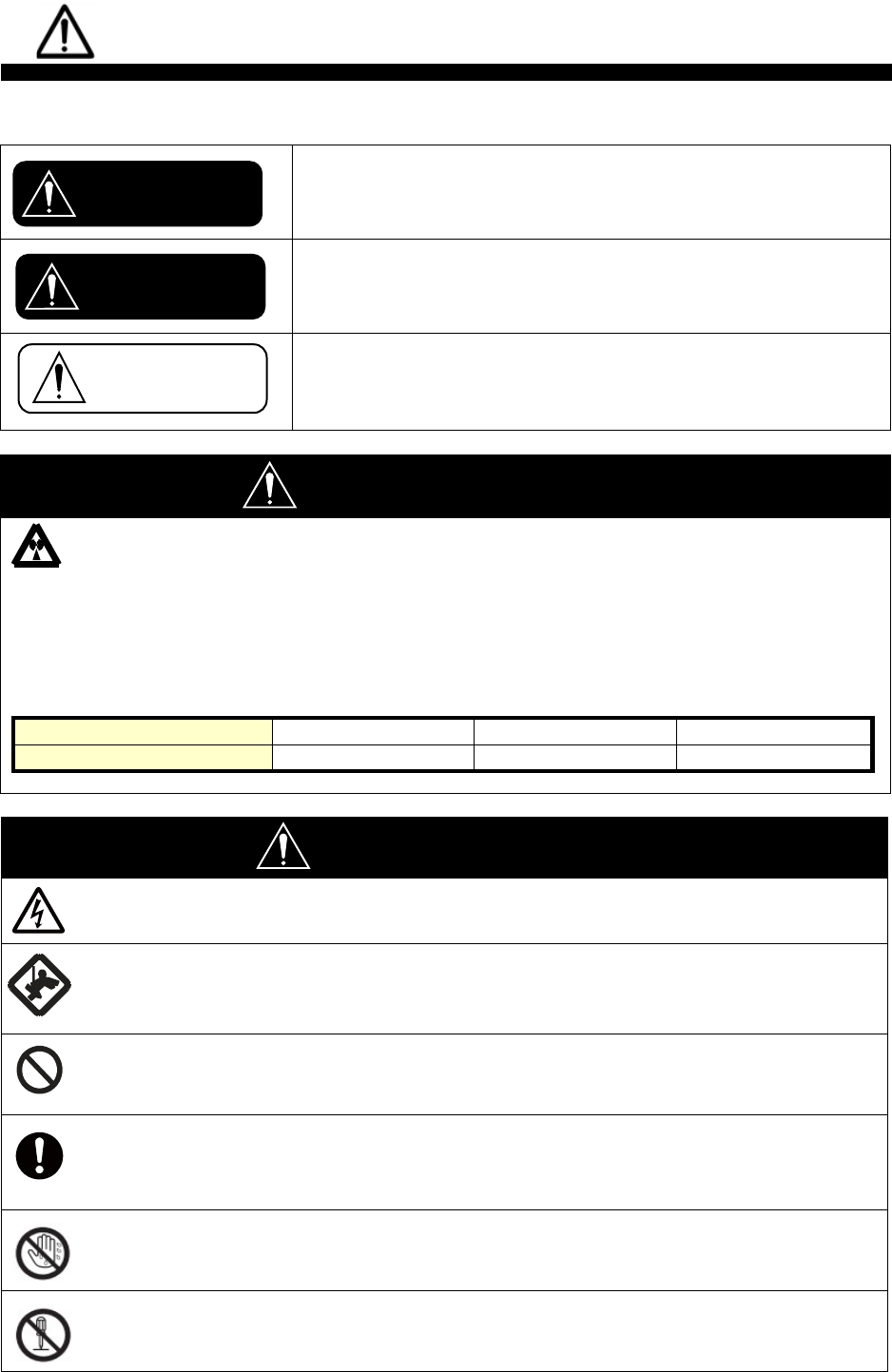
Indicates a hazardous situation which, if not avoided, will result
in death or serious injury.
Indicates a potentially hazardous situation which, if not
avoided, could result in death or serious injury.
Indicates a potentially hazardous situation which, if not
avoided,
can result in minor or moderate injury.
WARNING
Radio Frequency Radiation Hazard
The radar antenna sends the electromagnetic radio frequency (RF) energy. This energy can
be dangerous to you, especially on your eyes. Do not look at the radiator or near the
antenna when the antenna is rotating.
The distances at which RF radiation levels of 100 W/m 2 , 50 W/m 2 and 10 W/m 2 exist are
shown in the table.
DO NOT go near more than 5.9m (Safety standard is 10 W/m 2 ).
Distance from Antenna
1.1m
2.8m
5.9m
Power flux density
100 W/m 2
50 W/m 2
10 W/m 2
WARNING
Do not open the radome.
Electrical shock can occur. Only qualified personnel should work inside the equipment.
Wear a hard hat and safety belt when mounting the antenna
unit.
Serious injury or death can result if someone falls from the radar antenna.
Do not use any other power except 100 to 240 VAC.
Connection of an incorrect power supply can cause fire or damage the equipment.
Turn off the power immediately if water leaks into the
equipment or smoke or fire is coming from the equipment.
Failure to turn off the equipment can cause fire or electrical shock.
Do not operate the equipment with wet hands.
Electrical shock can occur.
Do not disassemble or modify the equipment.
Fire or electrical shock can occur.
CAUTION
WARNING
DANGER
SSE-14-0023_2
iii
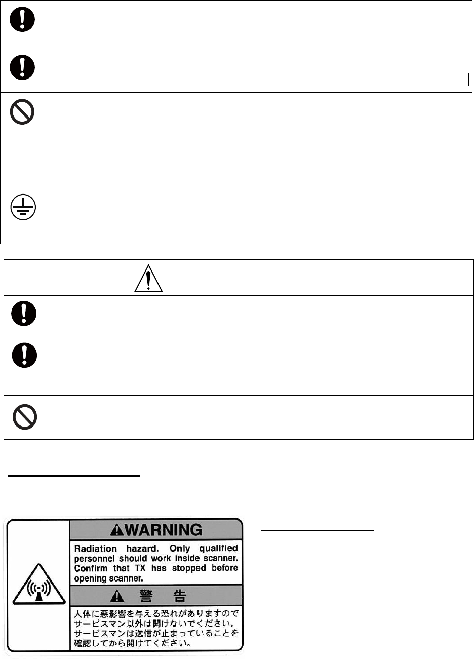
WARNING LABEL
Warning labels are attached to the equipment. Do not remove any label.
If a label is missing or damaged, contact us for the replacement.
Use only the specified power cable.
Fire or damage to the equipment can result if a different cable is used.
Use the power supply grounded certainly.
Electrical shock or defect of operation can occur.
When a thunderbolt is expected, do not approach a system or
do not touch a hand.
There is a possibility of receiving an electric shock.
A worker's safety is guaranteed although the measures which protect apparatus from
indirect lightning stroke serge are taken against this machine.
It is not a thing. Moreover, if a direct stroke is impressed, it may break down.
Attach securely protective earth to the unit.
The protective earth (grounding) is required to the AC power supply to prevent
electrical shock.
CAUTION
Do not put liquid-filled containers on the top of the equipment.
Fire or electrical shock can occur if a liquid spills into the equipment.
Establish space in the surroundings of apparatus as much as
possible.
It becomes a cause of performance degradation and failure.
Do not put any strong impact to LCD because of glass.
Serious injury may cause by broken glass.
Antenna Unit (radome)
Name: Radiation Warning Label
Type : 03-142-3201-0
number : 100-266-890-10

SSE-14-0023_2
Compact Dual Polarimetric X-band Doppler Weather Radar
WR-2100
Installation manual
CONTENTS
IMPORTANT NOTICES .......................................... i
SAFETY INSTRUCTIONS ......................................ii
System Configuration ............................................ v
1. System Summary ....................................... 1-1
2. Equipment Configuration ................................ 2-1
2.1. Equipment List ..................................... 2-1
2.2. Cable List ............................................. 2-1
3. Overall appearance ........................................ 3-1
4. Prior confirmation ............................................ 4-1
4.1. Confirmation items ............................... 4-1
4.2. Construction materials ......................... 4-1
4.3. Others ................................................... 4-1
4.4. Power equipment ............................... 4-1
4.5. Construction tools ................................ 4-2
4.6. Measurement ....................................... 4-2
4.7. LAN equipment .................................... 4-2
5. Precautionary item .......................................... 5-1
6. Construction .................................................... 6-1
6.1. Mount kit ............................................... 6-1
6.2. Antenna Unit ........................................ 6-2
6.3. Signal Processing Unit ......................... 6-7
6.4. Display Unit ........................................ 6-10
6.5. AC Power strip ................................. 6-10
7. Operation Test ................................................ 7-1
7.1. Before cover ......................................... 7-1
7.2. After cover ............................................ 7-2
8. Install TeamViewer ......................................... 8-1
9. PC operation .............................................. 9-1
9.1. File .................................................. 9-1
9.2. Disp ................................................. 9-1
9.3. Setting ............................................. 9-1
9.3.1. Setting .................................. 9-1
9.3.2. Service ................................. 9-5
9.3.3. Factory setting ...................... 9-9
9.3.4. Management list ................. 9-15
9.4. Radar Operation ........................... 9-19
9.5. Help ............................................... 9-19
9.6. Emergency Stop ........................... 9-19
9.7. Adjustment of Azimuth ..................
9-20
9.8. Total operation test ....................... 9-21
10. Menu Tree ............................................. 10-1
11. Specification .......................................... 11-1
11.1. Antenna Unit ............................. 11-1
11.2. Signal Processing Unit .............. 11-2
11.3. Display Unit ............................... 11-3
12. APPENDIX .......................................... 12-1
12.1. Outline drawing ......................... 12-1
12.2. System diagram .......................... 12-5
www.furuno.com
All brand and product names are trademarks, registered trademarks of service marks of their respective holders.
SSE-14-0023_2
v
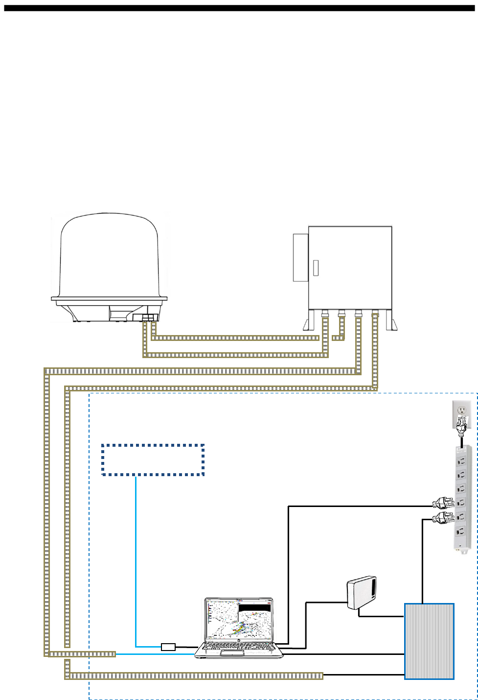
System Configuration
The observation system consists of an Antenna Unit (Radome), a Signal Processing Unit
(storage box) , and a Display Unit (indoor unit) are shown below.
(1) Antenna Unit (radome)
An antenna is stored in the radome, is turned, and radiates the radio waves.
The radiated waves are backscattered by precipitation particles on the propagation path,
return to the antenna, and are processed by RF converter to transfer the signals to the Signal
Processing Unit
(2) Signal Processing Unit (storage box)
Signal Processing Unit is stored in the storage box, and processes received signals digitally.
The digitally-processed signals are transferred to the display unit via 1000Base-T (LAN) .
(3) Display Unit (indoor unit)
The data is displayed graphically and stored with a general-purpose personal computer
(PC) .
WR-2100 ATU
WR-2100 SPU
Display Unit (indoor)
AC100-240
UPS
USB cable
AC100-240
AC cable
Display Unit
(Option)
USB cable
Existing LAN /
Inter net / Modem
LAN cable
LAN adapter
AC100-240
AC100-240
External HDD
AC cable
LAN cable
Coaxial cable
AC / Dsub cable
AC100-240
LAN ケcable
FURUNO
* Examples of using UPS
SSE-14-0023_2
1-1
1. System Summary
This system observes the development of rain clouds, outputs the strength of precipitation
and the speed of rain clouds (Doppler speed) , and observes phenomena of rainfall.
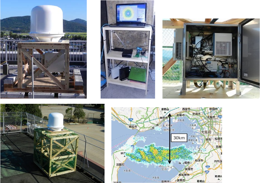
Features :
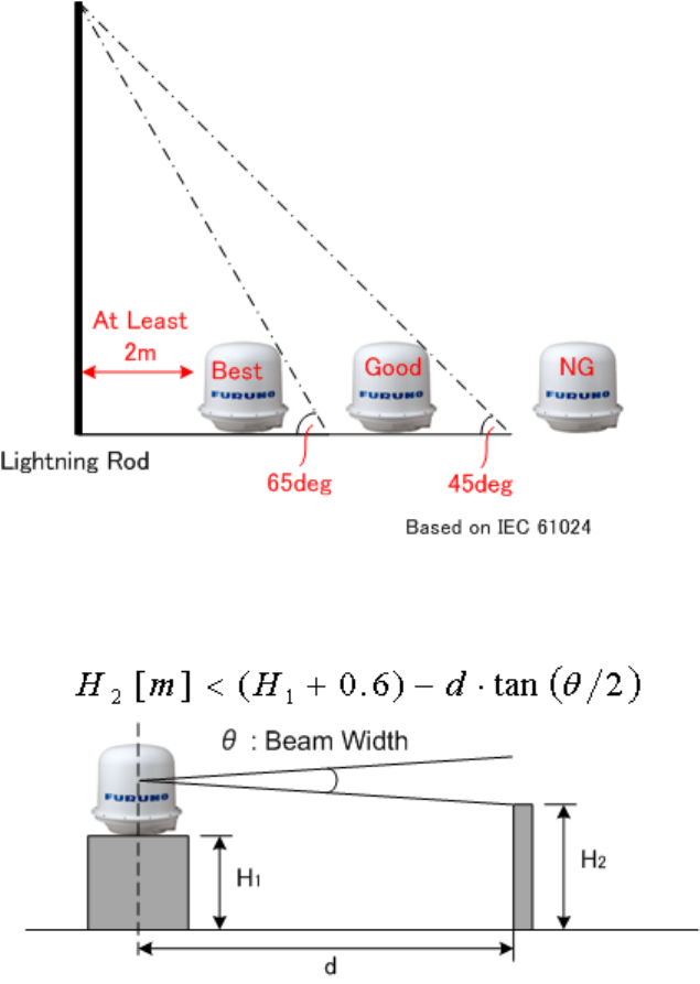
1. Installation to building roof in Urban area.
- Antenna must install in the safety area of lightning rod.
- Nothing should be surrounded around the antenna area.
SSE-14-0023_2
1-2
2. High Resolution Rain Observation, Rain Cloud, Density and Speed Observation.
3. Solid-state Transmitter replaces an aging device such as a magnetron.
SSE-14-0023_2
2-1
2. Equipment Configuration
2.1. Equipment List
PRODUCT NAME
MODEL
Compact Dual Polarimetric X-band Doppler Weather Radar
WR-2100
Items Units Descriptions Qty
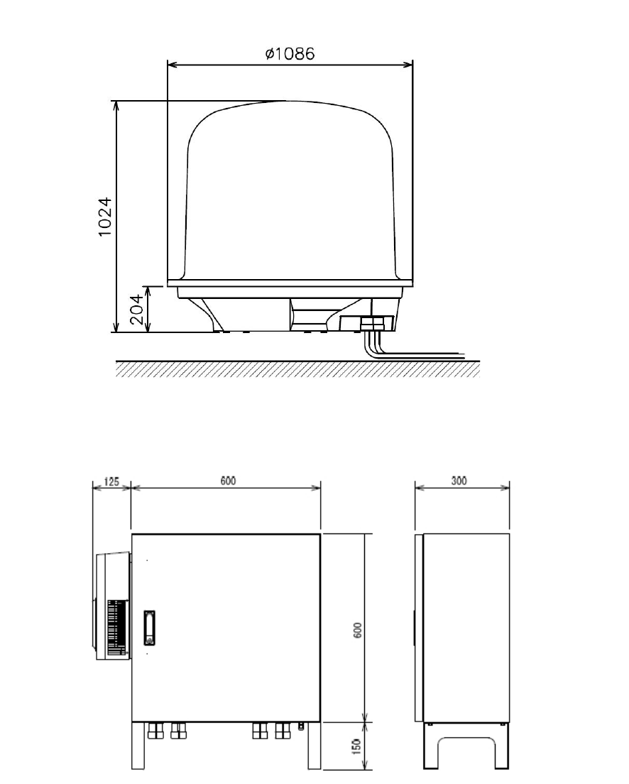
Antenna Unit WR-2100-ATU Size : Ф1086mm×H1024mm (include radome)
Weight : 70Kg
Weight of radome only: Upper 17kg, Bottom 9kg 1
Signal
Processing
Unit
WR-2100-SPU Size : W725×D300×H750mm (include storage box)
Weight : 60kg 1
Display Unit WR-2100-DPU General PC (ex. HP envy dv7) 1
Mounting Kit
for Radome
Type A Size : 900mm×800mm×t 10mm, Weight : 15kg 1
Type B Size : 950mm×920mm×t 10mm, Weight : 18kg
2.2. Cable List
Antenna Unit (radome) <-> Signal Processing Unit (storage box) cable
Items Descriptions Length Qty
Signal cable 25pin cable (Both Dsub-25pin) 5m 1
Com cable 9pin cable (Both Dsub-9pin) 5m 1
RF cable 3D-2W (Both SMA-P Connector) 5m 3
AC Power cable VCTF Power cable 3core 1.25sq 5m 1
Signal processing unit (storage box) <-> Display unit (storage box) cable
LAN cable
For outdoor 1000 Base-T Cat5e or better
by measure
1
AC power cable VCTF Power cable 3core 1.25sq
by measure
1
Protective tube for cable
Protective tube Flexible conduit
Inner diameter : 28 mm
radome --- storage box
by measure 2
Protective tube Flexible conduit
Inner diameter : 28 mm
storage box --- indoor
by measure 2
Earth wire
To protection against electric shock
by measure
1
SSE-14-0023_2
3-2
3. Overall appearance
2) Signal Processing Unit (storage box) .
1) Antenna Unit (radome)
Unit: mm
Unit: mm
SSE-14-0023_2
3-3
Specification List of draw (Refer to 12.1. Outline drawing)
No Items Drawing Number
1 Antenna Unit (Radome) 52-037-200G-2
2 Signal Processing Unit (storage box) 52-037-202G-0
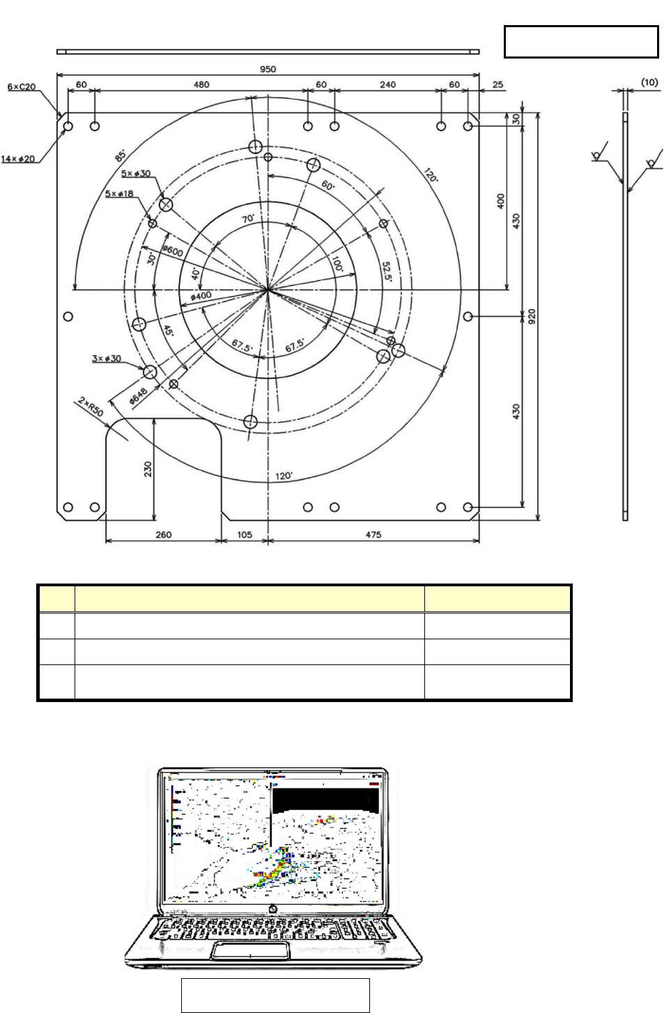
3 Mount plate of Radome
52-037-2301-1
52-037-2302-0
4) Display Unit (General Laptop PC)
Reference dimension :
418mm x 278mm x 37mm
Unit: mm
3) Mount plate of Radome
e.g. 52-037-2302-0

SSE-14-0023_2
4-1
4. Prior confirmation
4.1. Confirmation Items
1. The mount kit must be installed properly for Antenna Unit (radome).
2. Power cable (AC100V-240V) must be laid safely.
3. Power cable thickness should be selected depends on its length.
4. Frequency of AC power source must be 50Hz or 60Hz sin wave and single-phase current.
5. All engineers must wear the safety appliances such as a helmet, and safety shoes during an
installation of antenna unit. It is very dangerous that Antenna might hit a head by turning.
6. DO NOT look the antenna closer while radar is in operation. This energy can extremely
damage to the human body and especially to the eyes. Furthermore, DO NOT point the
antenna to the people closer while transmitting.
* The following table is shown the distance of Transmit radio wave to be 100W/m2, 50W/m2,
10W/m2. The value of Safe standard is 10W/ m2, do not go closer than 5.9m.
4.2. Construction materials
(include equipments in “2. Equipment Configuration”)
Items Descriptions Qty
M10x35 Hexagon Bolt Material : SUS304 (Fix for up/down parts of radome) 12
M10 Spring Washers Material : SUS304 (Fix for up/down parts of radome) 12
M10 Flat Washers Material : SUS304 (Fix for up/down parts of radome) 12
M12x40 Hexagon Bolt Material : SUS304 (Fix for radome and mount plate) 5
M12 Spring Washers Material : SUS304 (Fix for radome and mount plate) 5
M12 Flat washers Material : SUS304 (Fix for radome and mount plate) 5
M16x40 Hexagon Bolt (*1) Material : SUS304 (Fixed for mount plate and a base) 12
M16 Nut Material : SUS304 (Fixed for mount plate and a base) 12
M16 Spring Washer Material : SUS304 (Fixed for mount plate and a base) 12
M16 Flat Washer Material : SUS304 (Fixed for mount plate and a base) 24
FV2-M4 Round Crimping Terminal For electric cables 6
Putty for pipe Non-hardening, Electric insulation qs
Multi Plug Outlet Power strip (3-core) 4-Outlets minimum w/ surge protector 1
Heavy Duty Cable Tie (2 types) Nylon 6/6 w/ weather resistance 140mm, 300mm 100
M10 Anker Bolt Fixed for SPU 4
Earth wire 2sq green To protection against electric shock 1
*1: Length of Hexagon Bolt will depend on a thickness of a base.
4.3. Others
Items Descriptions Qty
Key of storage box No.200 2
4.4. Power equipment
This equipment must need 1KVA x1 line of power, with ground outlet (3 pin type)
SSE-14-0023_2
4-2
4.5. Construction tools
Items Descriptions
SMA Torque wrench
74Z-0-0-21 SMA connector conclusion
Substitute : Caliber 5/16 inch or 8mm wrench
Socket Wrench
(4 types) M8 (13mm), M10 (17mm), M12 (19 mm)、M16 (24mm)
hexagon bolt (Substitute : Monkey wrench)
Hexagon Wrench
(3 types of Ball-point)
M3 (2.5mm), M4 (3mm), M5 (4mm)
Bolt with Hexagon hole
[+] Driver No.1 Dsub-9pin
[+] Driver No.2 M3, M4, M5, Dsub-25pin, for Electric Filter
[+] Driver No.2 (Long type) Length 30cm minimum fixed for PXI
[-] Driver M8 Multiuse
Box Driver (2 types) 5mm, 5.5mm fixed for Dsub connector
Flat Ratchet (3 types) M10 (17mm), M12 (19mm), M16 (24mm)
Nipper For wiring work
Wire Strippers For wiring work
Electrical workers knives For wiring work
Crimped Terminal tool 1.25sq Power cable (M4), GND wire (M8) for wiring work
Tape Measures (5m minimum) Measure length of outdoor power cable and LAN cable
Self-fusing Tape (Black) Fit Tape insulation / protect (Length 10m)
Electrical Tape (Black) Heat & Fire proof (L19m x W20mm x D0.18mm)
Curing Tape Multiuse
Chemiseal S-8400W Aluminum Tube 50G
Silicone grease Temperature range -30 to +200 °C
Safety belt For high place work
4.6. Measurement
Items Descriptions Remarks
Digital Multi Meter Voltage
AC : 85 to 240 V
DC : 1 to 50V
Current
AC : 1 to 10 A
DC : 1mA to 1A
Resistor
0.1 to 10M ohm Tester
Lead Cables
Angle Meter Measurement range : ≧ 45deg
Accuracy : within ±0.2deg
Zero adjustment
vertical angle
of RADAR
4.7. LAN equipment
1) Use Cat5e (or better grade) of 1000Base-Tx LAN cable for transferring the data from display
unit to output equipment.
2) Be prepared High speed broadband (approx.100Mbps) for using remote maintenance.
*Low speed broadband may cause slow access on remote to support a system.
SSE-14-0023_2
5-1
5. Precautionary item
1) Use only the commercial power supply of single phase 100-240VAC.
2) DO NOT overhaul or remodel.
3) DO NOT work during the thunder is occurring.
4) DO NOT scratch, cut, forcedly bend, pull, twist, bundle, or damage the power cable. Also, not to
put a heavy thing on top or interpose.
5) DO NOT touch inside equipment with a wet hand.
6) Connect the ground conductor for protecting equipment and electric shock prevention from
lightning induction and ground leakage.
7) Cleaning instruction: Use dried soft cloth to wipe the surface. If it is difficult to remove stains, use
the cloth soak with a neutral detergent to clean it. Please DO NOT use an alcohol or an organic
solvent (e.g.: thinner) to clean it.
For optional equipment:
Please refer to attached documents of UPS, Router, and other equipments separately.
SSE-14-0023_2
6-1
6. Construction
All installation places will be considered for installing PC, cables, pipes, and mount kit during the
environmental survey.
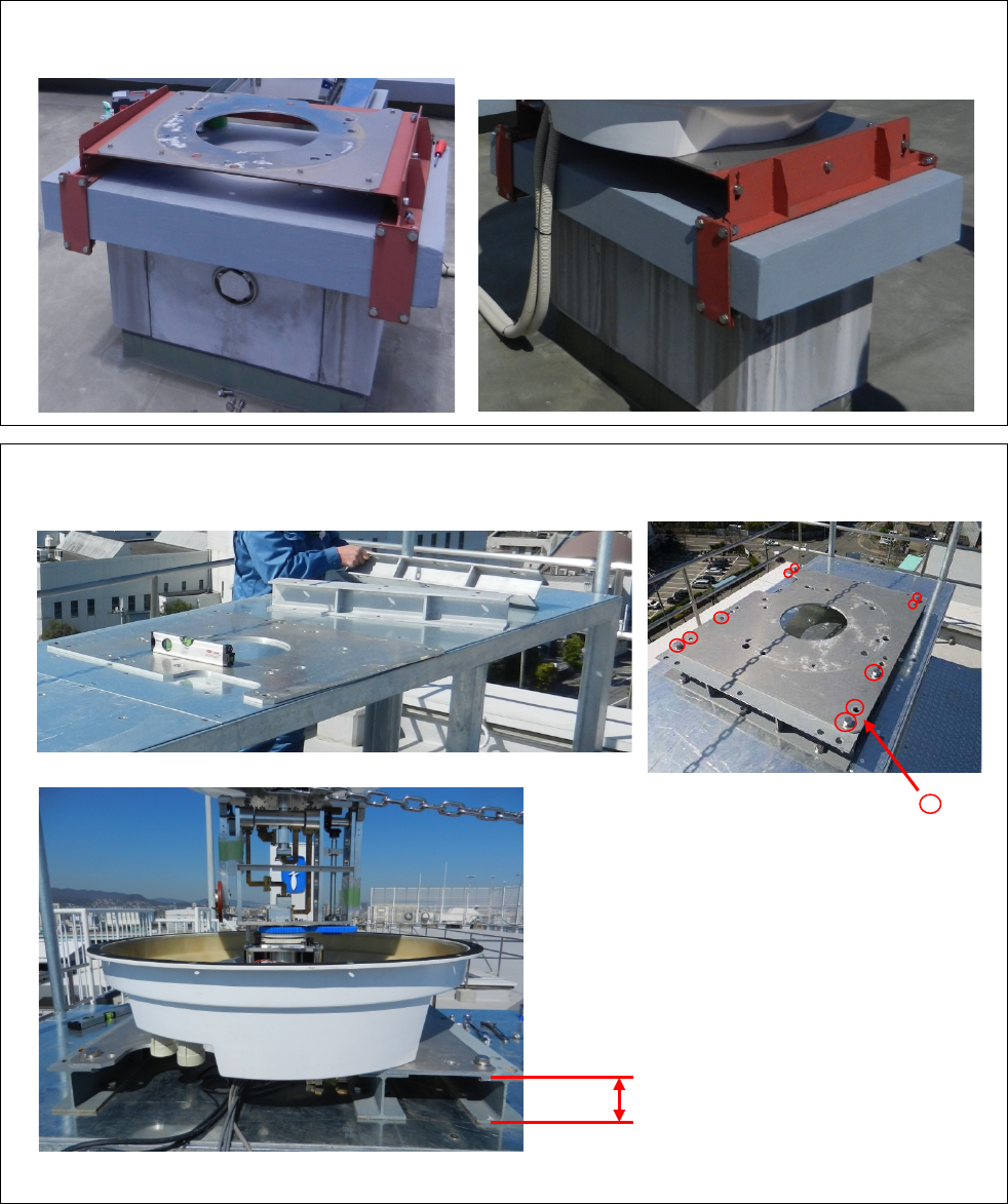
6.1. Mount kit
<Case 1>
The case of not able to make a hole on pedestal.
<Case 2>
The way of using steel frames.
Open more than 100mm of space.
Adjust the hole (10 holes [ ] )
with the
mount plate and the
steel frames. Make holes to the
steel frames with 20Φ
for M16
hexagon bolt
to join with the
mount plate.
SSE-14-0023_2
6-2
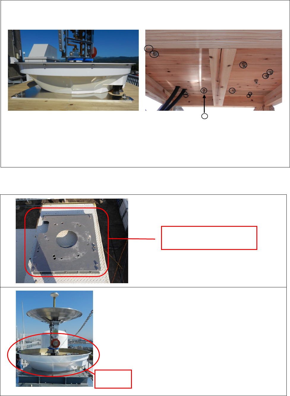
<Case 3>
The way to put the mount plate directly on to a wooden pedestal.
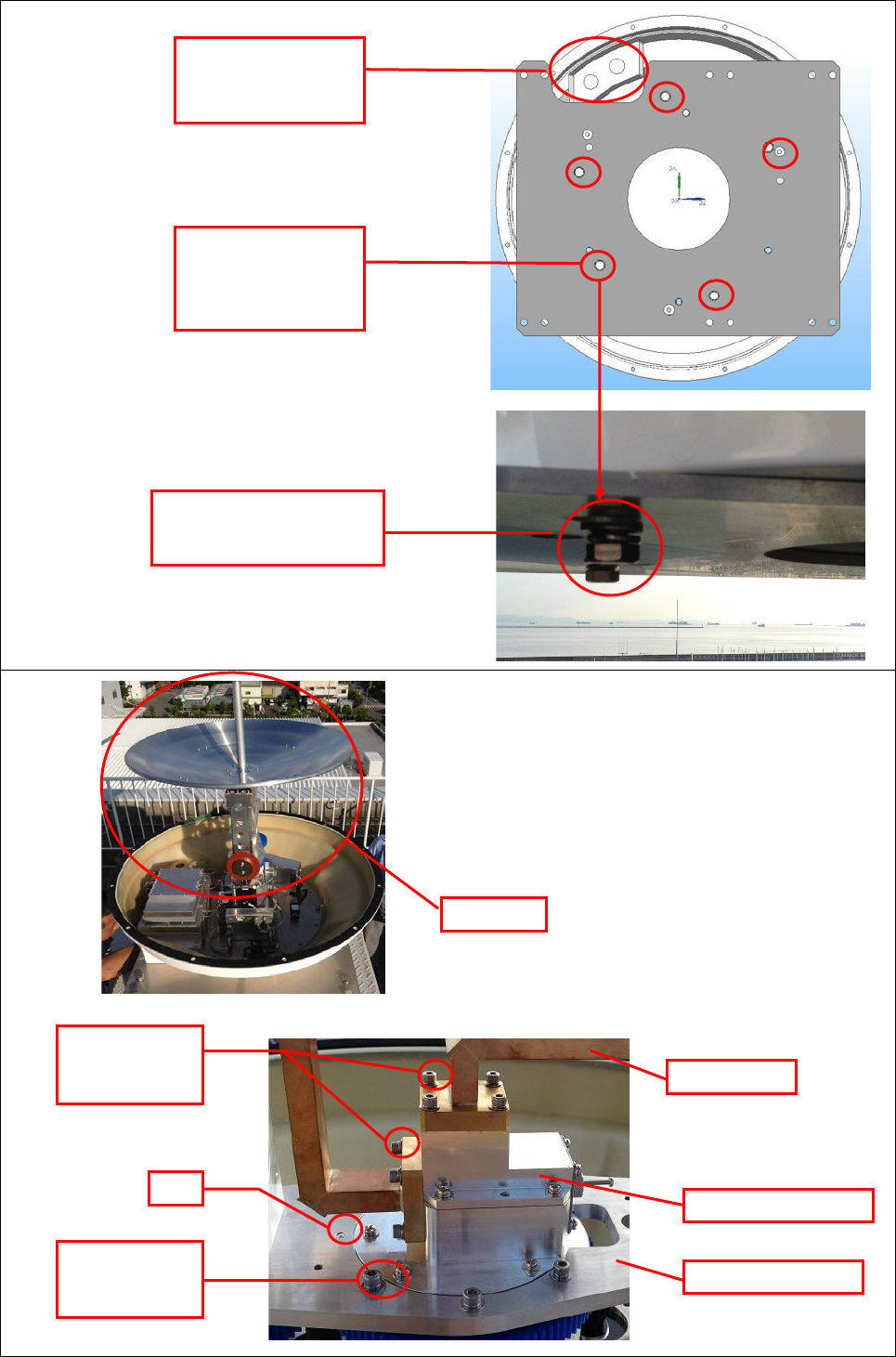
6.2. Antenna Unit (Radome)
1
.
Set up the base.
2
.
Set the bottom of radome to the base.
(1) Adjust the cable introduction of under
radome to notch of the base.
(2) To fit the bottom of radome with five
salient into the base hole
(3) To fix 5 pcs of M12x35 hexagon bolt
(with M12 spring washer, M12 flat
washer) to join the base and radome.
The mount plate
(900mm×800mm×10mm)
Make 10 holes [ ] to a wooden pedestal
with 20Φ for M16 hexagon bolt to join with
the mount plate.
In this case, it may need to make 2 big holes
for Protecting Tube to get through.
Bottom of
radome
SSE-14-0023_2
6-3
Under view:
3
.
In case to reinstall the antenna
(1) Fit the pin of Rotary waveguide
(2) Fix the rotary pedestal by 6 pcs of
M5x15 with hexagon bolt hole
SEMS B.
(3) Fix the waveguide by 2 pcs of
M4x15 with hexagon bolt hole
SEMS B.
Hole of the mount
plate & Salient of
the bottom of
radome
Notch & Cable
instruction of the
mount plate
M12x35 hexagon bolt
M12 spring washer
M12 flat washer
Antenna
M4x15 with
hexagon bolt
hole SEMS B
Pin
M5x15 with
hexagon bolt
hole SEMS B
Waveguide
Rotary waveguide
Rotary pedestal
SSE-14-0023_2
6-4
4. Every location must have to measure a length in between ATU
SPU
DPU for
adjustment. And to lay the Protecting Tube.
5. Insert the outdoor cable into the
cable waveguide (6 pcs).
Protecting Tube 1 :
- AC Power cable (3cores)
Protecting Tube 2 :
- Coaxial Cable (3 pcs)
- Communication cable
(both end Dsub-25pin connector)
- Signal cable
(both end Dsub-9pin connector)
Remove the connector cover of
Dsub-25pin and 9pin while sending
through the Protecting Tube to the
other side.
Basically Coaxial cable is up to 5m.
(15m maximum)
SPU DPU
(Indoor)
PT 2
PT 1
PT 4
PT 3
ATU
Fix by fastening plate
Dsub25pin connector
Dsub25pin connector
Connector cover
SSE-14-0023_2
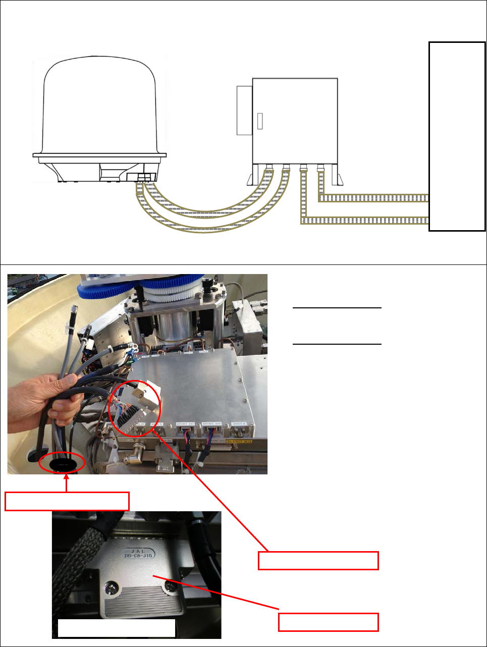
6-5
6. Wire the RF Unit
(1) Connect all cable with following the
name of tag on cable and label on
the unit.
(2) Connect / Fix coaxial cable (3 pcs)
with torque wrench (74Z-0-0-21).
(3) Connect / Fix communication cable
(both end Dsub-25pin connector)
with L type Offset driver +1 (TD-61).
7
.
Wire the MTR Unit
(1) Connect the Signal cable (both end
Dsub-9pin connector)
(2) Tighten 2 screws of connector fix by (+)
driver
8. Tighten all screws of Dsub connector by
(+) driver or socket wrench.
Torque wrench
L type Offset driver +1
RF Unit
Signal cable
Coaxial cable
Communication cable
SSE-14-0023_2
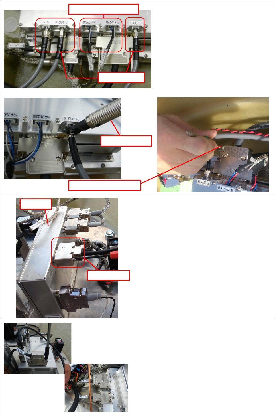
6-6
9
.
Wire the power filter
Caution: Make sure an electric current is not flow
(1) Fix / Connect AC power cable (3pin)
(2) Confirm the circuit diagram of power filter
label before connecting.
(3) Connect the LINE side to match with the line
color of LOAD side and LINE side.
<Wire color>
Type JIS IWR US EU
P/L + Black Black Black Brown
N - White White
White
or Gray
Blue
GND FG Green/
Yellow
Red
(Terminal
Green)
Green Green/
Yellow
10
.
Activation test
- Turn “ON” the switch of Antenna rotary motor.
Antenna rotary motor
switch “OFF”
Antenna rotary motor
switch “ON”
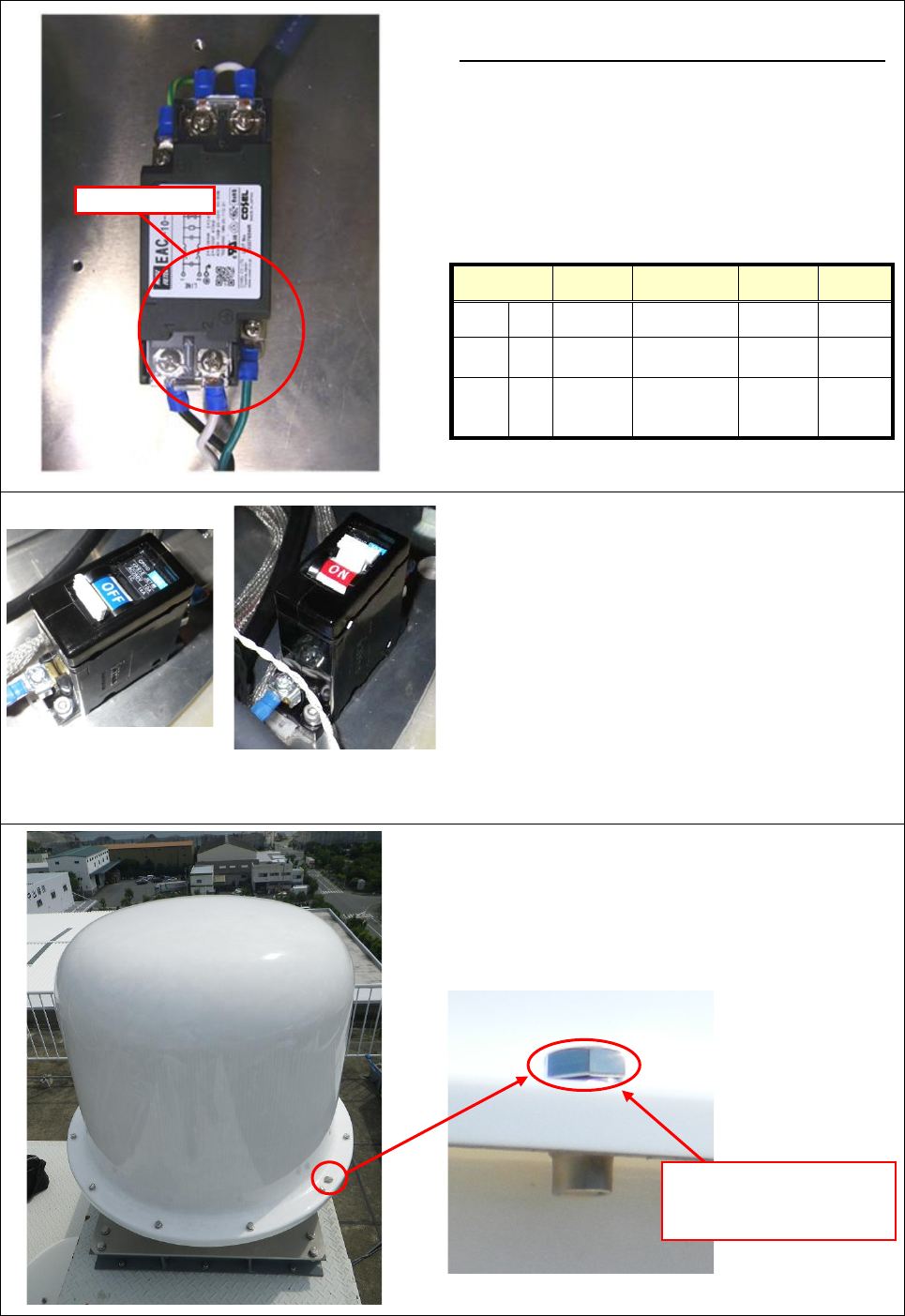
11
.
Cover the top of radome
- Make sure the switch of antenna rotary motor
is “ON” before put on the top part of radome
- Fix the upper part of radome and the bottom
part of radome by 10 pcs of M10x35 bolt.
Power filter
M10x35
M10 spring washers
M10 flat washers
SSE-14-0023_2
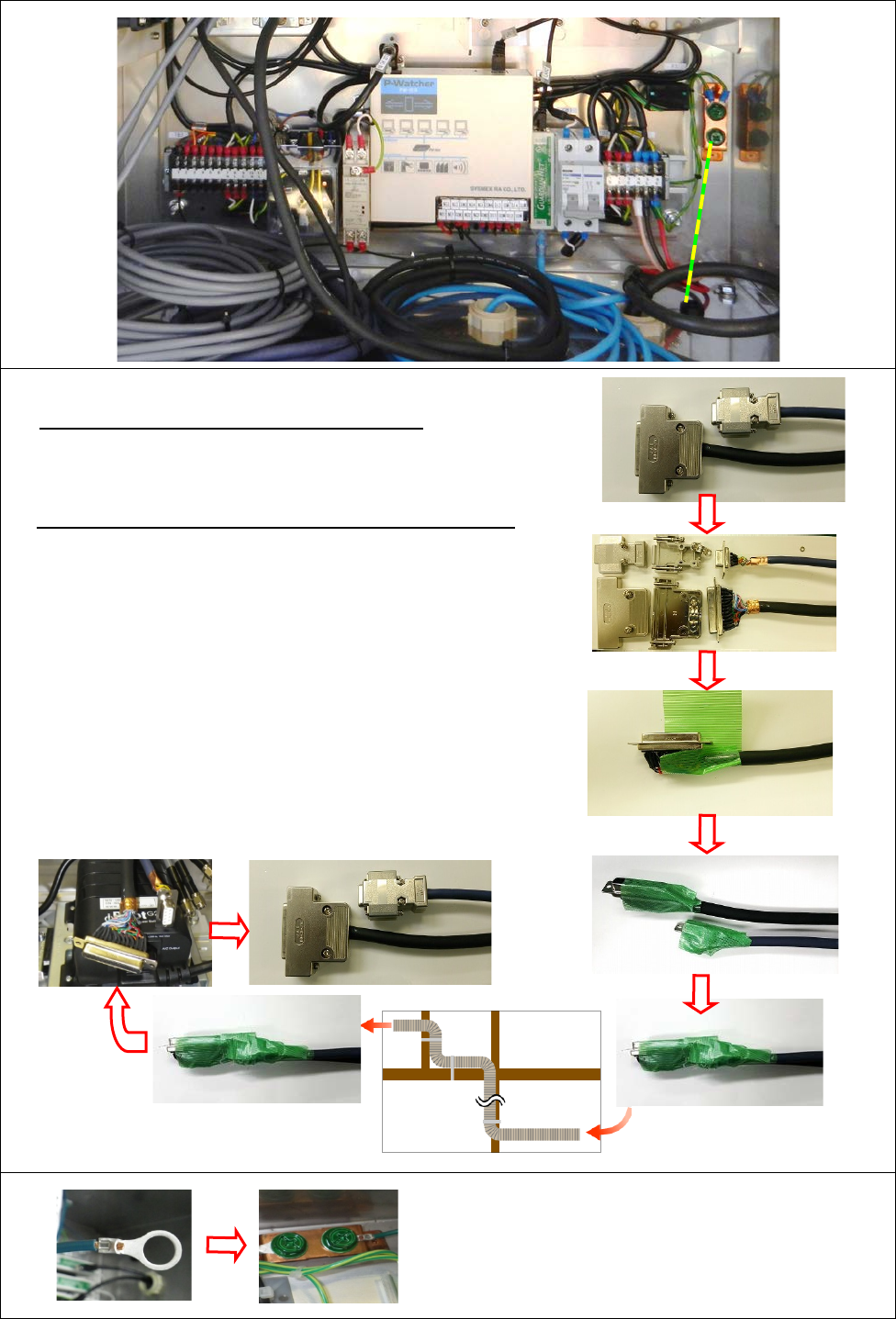
6-7
6.3. Signal Processing Unit (Store into storage box)
1
.
Insert outdoor cable into cable waveguide (10 pcs)
Cables run between SPU and Display Unit
Protecting Tube 4 : AC power cable (3pin)
Protecting Tube 3 : LAN cable
Cables run between SPU and Antenna Unit (radome)
Protecting Tube 2 : Coaxial cable (3 pcs)
Protecting Tube 1 : AC power cable (3pin)
Communication cable
(both end Dsub-25pin connector)
Signal cable
(both end Dsub-9pin connector)
Remove the connector cover and run Dsub-25pin
connector and Dsub-9pin connector through Protecting
Tube. Reinstall the cover after passed through the
Protecting Tube.
・Insert the GND wire through the GND/Cable ground.
2
.
Connect FG cable
- Crimp the crimped terminal (M8) to the cable
- Screw up the cable to the FG terminal.
- This FG terminal should be connected with
the building grounding electrode system.
*Taping it with coaxial
cables
Protecting Tube
SSE-14-0023_2
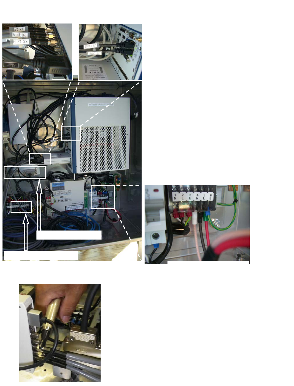
6-8
3
.
Connect the cable from Display Unit
*Caution: Make sure an electric current is not
flow
(1) Connect the AC power cables (3pin) to the
terminal base (TB1)
(2) Connect SPU Unit LAN cable to the
connector F3-LINE
(3) Connect LAN cable (for the Power switch)
to the connector F2-LINE
4
.
Connect the cable of the Antenna Unit
(radome)
(1) Connect the AC power cables (3pin) to the
terminal base (TB3)
(2) Connect and fix the signal cable (Dsub-9pin
connector) to each S-COM connector, and
communication cable (Dsub-25pin
connector) to RF-CONT SIG connector.
(3) Fix with the torque wrench (74Z-0-0-21)
after connecting 3 coaxial cables (TX IF,
RX IF V, RX IF H) to SPU – UNIT
connector.
5
.
Fix the wire
- Fix the cable tie with slacking the cable
without making a tension to the connector
of communication cable (Dsub-25pin
connector), signal cable, and coaxial
cables (3 pcs).
3. (2)(3) LAN cables
4. (3) Coaxial cable
4. (2) Signal cables
4. (1) AC power cables
3. (1) AC power cables
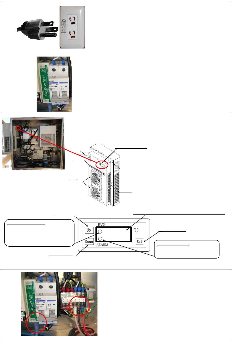
SSE-14-0023_2
6-9
6
.
Make the power plug (beside Display Unit)
- Make 3 pin earthed power plug that running
through the SPU.
- Place an outlet
7. Activation test
- Turn on the power breaker.
- Follow the instruction to test it.
8. Cooler setting
Setup temperature of cooler to 25 Celsius
degrees . (1) Press [Set] button to
indicate a temperature
of setting.
(2) Press [Up], [Down]
button to setup a
temperature to 25
Celsius degree.
(3) Press [Set] button to
indicate a current
temperature.
9. Measure the AC power
- Measure the value of AC power that comes
into SPU from the main outlet.
- Reference range: -10% to +10%
10. Connect LAN cable to
connect with display
unit.
Control panel
Display (Temperature will indicate when power up)
Setup button
Alarm lamp (RED)
Lamp ON: Alarm occurs
Lamp Blink: Forced heater ON
Down button
Up button
Alarm lamp (GREEN)
Lamp ON: Cooler ON
Lamp OFF: Cooler OFF
0.5S Lamp Blink: Forced cooler ON
1.0S Lamp Blink: Heater ON
Air inlet
Terminal unit
Air inlet
Air fan
and outlet
25
SSE-14-0023_2
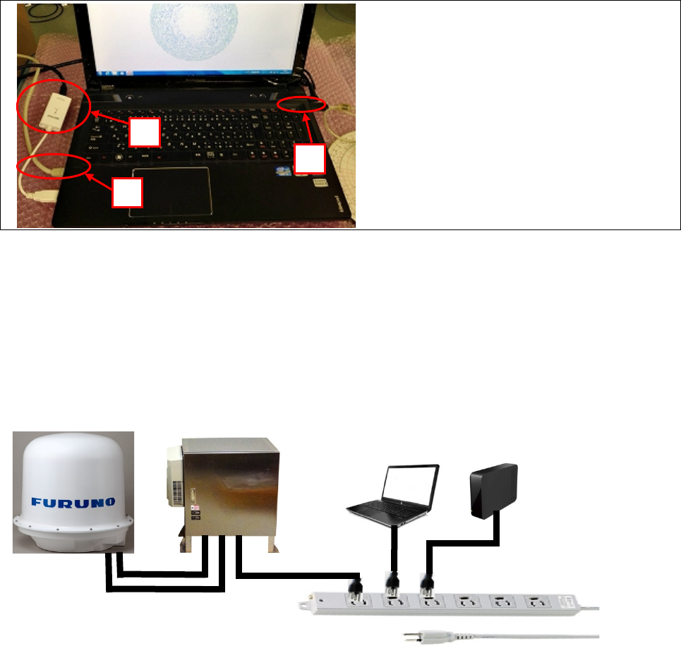
6-10
6.4. Display Unit (General laptop PC)
6.5. AC Power strip
Setup 4 or more outlet of AC power strip (3 core) beside display unit for display unit, HDD, and
radar unit. UPS and Switching Hub / Router may be used(that depends on an order).
Notice: To lay LAN cable between PC and modem/router during installation when customer
prepare an internet environment with modem/router for using remote control.
1.Setup Display Unit (PC)
(1) Connect LAN cable from SPU to PC
(2) Connect AC power cable
(3) Connect LAN cable from modem to
USB LAN adaptor for PC
③
①
②
WR2100-RDP
External
HDD
WR2100-SPU
WR2100-ATU
SSE-14-0023_2
7-1
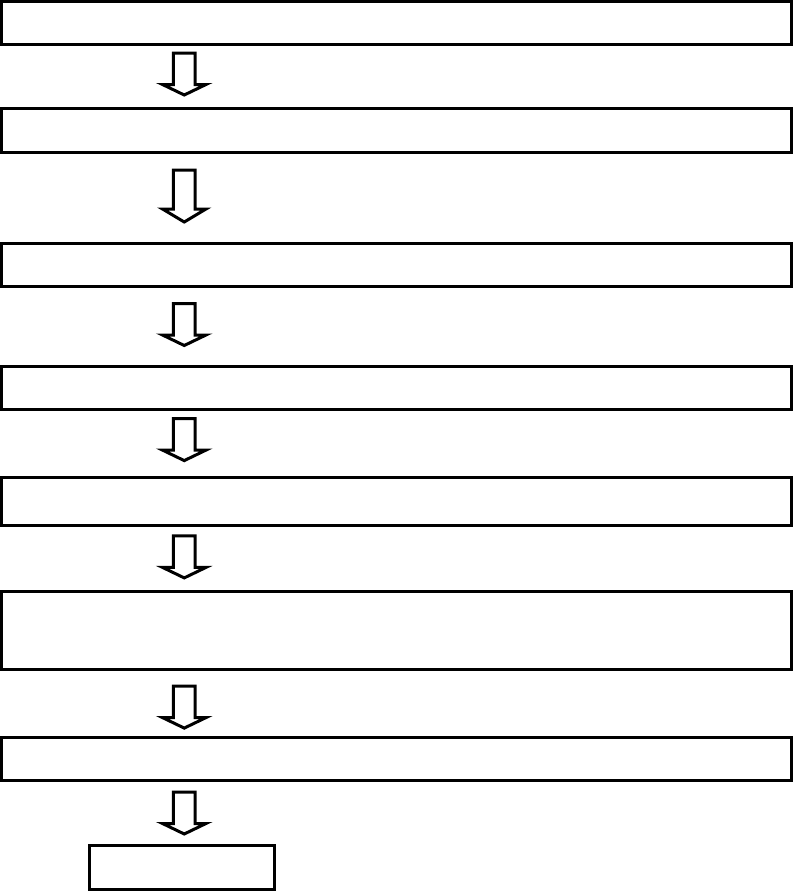
7. Operation Test
Follow the step as below :
7.1. Before cover (Upper part of radome)
*It might cause a damage to the human body,
especially to eyes if receiving the transmit radio wave
directly in short distance.
(1) Turn on the power of Display Unit (PC)
(2) Stay away from radar farther than 5.9m
(8) Cover radome
(4) Start the observation from the menu of the display unit
Complete
(3) Place an outlet (main power) to supply the power to radar unit
(5) Stop rotate radar and emission (STBY).
(6) Adjust an angle of elevation to 0 by angle meter
(refer the instruction of adjustment from separate sheet)
SSE-14-0023_2
7-2
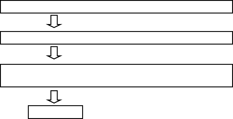
7.2. After cover (Upper part of radome)
(1) Be sure the power of radar unit and Display Unit (PC) are ON.
(2) Start the observation from the menu of the display unit
Complete
(3) Set to indicate the observation state, picture to the Display Unit, and to output
the data periodically.
SSE-14-0023_2
8-1
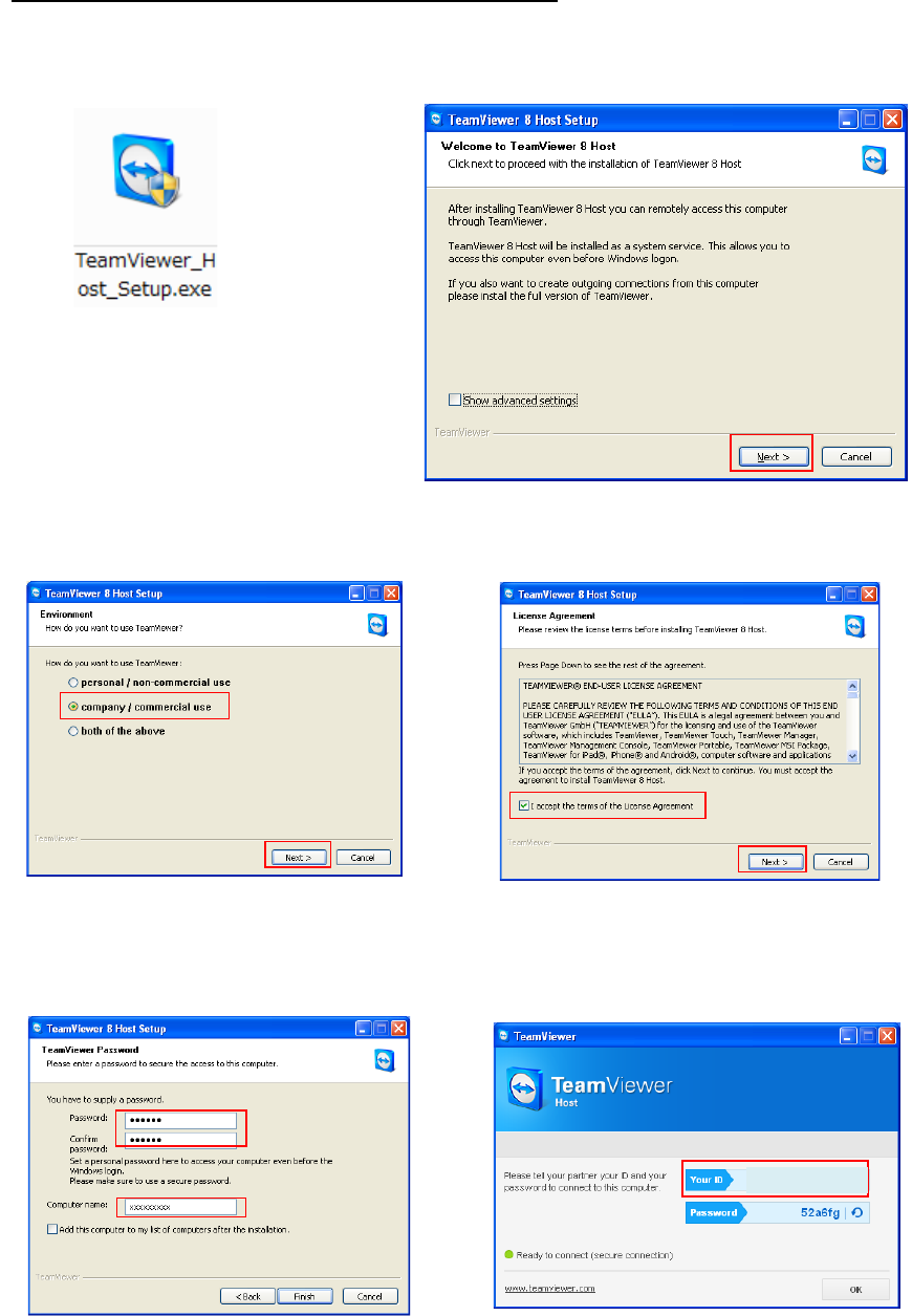
8. Install TeamViewer (Remote control management tool)
1. Download the software of TeamViewer Host (For remote server) from the following web site:
http : //www.teamviewer.com/ja/download/windows.aspx
2. Double click “TeamViewer_Host_Setup.exe” to install the software.
3. After installed software, please inform “Your ID” to the headquarter of Furuno who is in charge.
4. Use other PC to confirm remote access by TeamViewer.
(6) “Your ID” will be issued automatically.
(* Remember this ID)
And then click [OK]
(1)
Double click the icon
(2) Click [Next]
(3) Select “company / commercial use”,
and then click [Next]
(4) Check on “License Agreement”, and
then click [Next]
(5) Make password and computer name
Password: rmsrms (enter this password)
Computer name: Enter location’s name
And then click [Exit]
123 456 789
SSE-14-0023_2
8-2
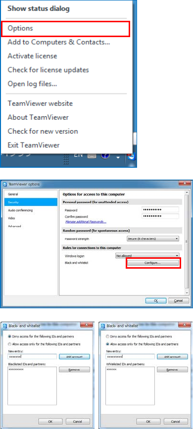
5. The following instruction is to setup security on TeamViewer Host if necessary.
* Please confirm to a customer and Furuno Headquarter before setup.
(1) Right click to the icon of TeamViewer in
task bar.
(2) [TeamViewer options] will indicate a
Popup menu on a screen after clicked
[Option] from dropdown list of
TeamViewer.
(3) Click [Security] on the right list of
[TeamViewer options]
(4) Click [Configure] of [Black and whitelist]
under a menu of [Rules for connections
to this computer].
(5) It could register an opponent ID on the
list to whether [Deny access for the
following IDs and partners] or [Allow
access only for the following IDs and
partners] from Popup menu of [Black
and whitelist].