Contents
- 1. User Manual 1
- 2. User Manual 2
- 3. User Manual 3
User Manual 2
69
<Functions of Linkage Menu>
S1
<Edit dial>
● Select the function name
and return to the Linkage
menu by pushing the RTN
button or pushing the
Home/Exit button.
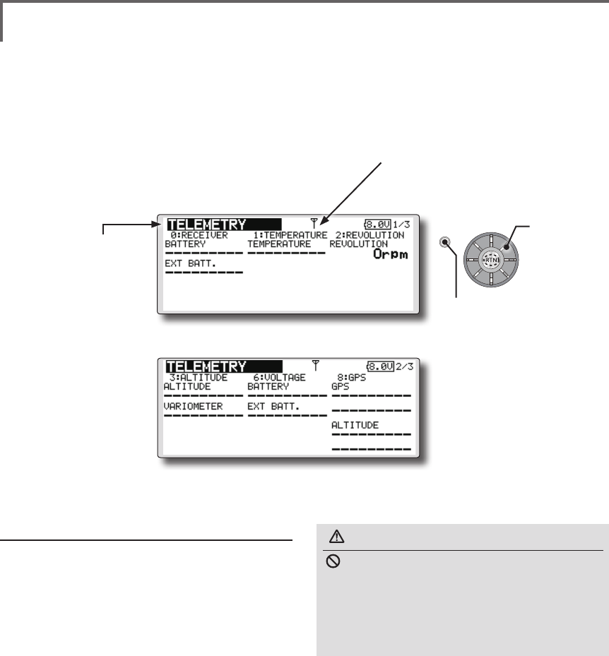
TELEMETRY Displaying data from the receiver
This screen displays your choice of data from the
receiver.
Also warnings can be activated regarding
other data from your aircraft. For example, if the
receiver voltage drops, the user can be warned by
an alarm (and vibration).
*Only receiver voltage can be used in FASSTest 12CH mode.
*The FASSTest 18CH mode can use all the telemetry
functions.
● Select [TELEMETRY] in the Linkage menu and access the
setup screen shown below by pushing the RTN button.
● Push S1 button to advance to next page.
How to see telemetry data
1. Telemetry screen can be called select
[TELEMETRY] in the Linkage menu and access
the setup screen by pushing the RTN button.
2. If each item is chosen and the RTN button is
pushed, an alarm setup can be performed
with the minimum/maximum after a
transmitter is turned on.
*Receiver voltage can be checked immediately. An optional
sensor will need to be attached to S.BUS2 of a receiver if
you would like to see other information.
*No special setup is necessary if each sensor displayed
is left as in the default setup. Separate sensor ID
is also unnecessary. However, if two or more of
one kind of sensor is used, setup is required in the
"SENSOR" menu.
WARNING
Do not watch the transmitter screen during
ight.
*You may loose sight of the aircraft during ight and this
is extremely dangerous. Have an assistant on hand to
check the screen for you. A pilot should NEVER take
his eyes off his aircraft.
Scrolling
● Moving cursor
● Receiver → Transmitter. The reception
strength is shown.
● Push the S1 button
to call next page.
70 <Functions of Linkage Menu>
S1
<Edit dial>
● Select the function name
and return to the Linkage
menu by pushing the RTN
button or pushing the
Home/Exit button.
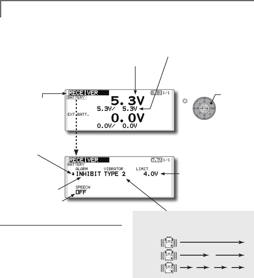
TELEMETRY : RECEIVER [BATTERY] Displaying data from the
receiver battery voltage
In this screen, the battery voltage of a receiver is
displayed.
If it becomes higher or lower than the setting an
alarm and/or vibration will alert you.
*Only receiver voltage can be used in FASSTest 12CH mode.
*The FASSTest 18CH mode can use all the telemetry
functions.
● Select [Rx-BATT.] in the TELEMETRY screen
and access the setup screen shown below
by pushing the RTN button.
● Select [BATTERY] in the RECEIVER screen
and access the setup screen shown
below by pushing the RTN button.
●A setup of the voltage on
which the alarm operates.
Scrolling
● Moving cursor
● Receiver battery voltage
● The maximum and the minimum when
powering ON are shown. It will be preset,
if a cursor is moved to this place and the
RTN button is pushed for 1 second.
● ↓The "down" arrow will
indicate that an alarm will
sound when the voltage
drops to below the setting.
● ALARM is chosen from
BUZZER, VOICE, and
INHIBIT.
● The ON/OFF switch of SPEECH is chosen.
Alarm set
1. Move the cursor to the ↓ALARM item, and
it chooses from BUZZER, VOICE, INHIBIT, and
pushes RTN.
2. When not operating vibrator, it is "VIBRATOR"
to INHIBIT. TYPE1-3 will be chosen if it is made
to operate.
3. Move the cursor to the LIMIT [4.0V] item and
push the RTN button to switch to the data
input mode.
4. Ajust the rate by scrolling the edit dial.
Initial value: 4.0V
Adjustment range: 0.0V~100.0V
*When the RTN button is pushed for one second, the rate is
reset to the initial value.
5. Push the RTN button. (To terminate the input
and return to the original state, push the
Home/Exit button.)
TYPE 1
TYPE 2
TYPE 3
"VIBRATOR" type
If the following types are selected, the transmitter
will vibrate during the warning.
71
<Functions of Linkage Menu>
S1
<Edit dial>
● Select the function name
and return to the Linkage
menu by pushing the RTN
button or pushing the
Home/Exit button.
● Select [Rx-BATT.] in the TELEMETRY screen and
access the setup screen shown below by
pushing the RTN button.
Alarm set
1. Move the cursor to the ↓ALARM item, and
it chooses from BUZZER, VOICE, and INHIBIT,
and pushes RTN.
2. When not operating vibrator, it is "VIBRATOR"
to INHIBIT. TYPE1-3 will be chosen if it is made
to operate.
3. Move the cursor to the LIMIT [4.0V] item and
push the RTN button to switch to the data
input mode.
4. Ajust the rate by scrolling the edit dial.
Initial value: 4.0V
Adjustment range: 0.0V~100.0V
*When the RTN button is pushed for one second, the rate is
reset to the initial value.
5. Push the RTN button. (To terminate the input
and return to the original state, push the
Home/Exit button.)
TYPE 1
TYPE 2
TYPE 3
"VIBRATOR" type
If the following types are selected, the transmitter
will vibrate during the warning.
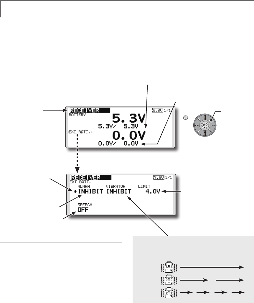
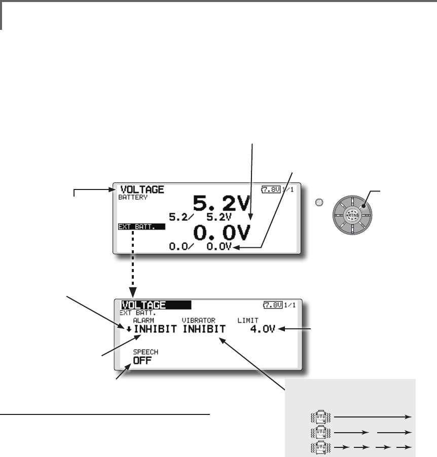
TELEMETRY : RECEIVER [EXT BATT.] Displaying data from the EXT
battery voltage port
The EXT-VOLT screen will display the data from
the EXT-battery output from the R7008SB receiver.
In order to use this function, it is necessary to
connect external voltage connector of the R7008SB
receiver to a CA-RVIN-700 or SBS-01V to the
battery you desire to measure the voltage of the
EXT-battery.
You will be alerted by an alarm or vibration if
the voltage set by you is exceeded.
*FMR-03 isn't equipped with EXT-battery port.
*Only receiver voltage will be received in the FASSTest 12CH
mode.
*The FASSTest 18CH mode will display all telemetry data.
*CA-RVIN-700 must be installed in the aircraft.
● Select [EXT BATT.] in the RECEIVER screen
and access the setup screen shown
below by pushing the RTN button.
●A setup of the voltage on
which the alarm operates.
Scrolling
● Moving cursor
● EXT battery voltage ● The maximum and the minimum
when powering ON are shown. It will
be preset, if a cursor is moved to this
place and the RTN button is pushed
for 1 second.
● ↓The "down" arrow will
indicate that an alarm will
sound when the voltage
drops to below the setting.
● ALARM is chosen from
BUZZER, VOICE, and
INHIBIT.
● The ON/OFF switch of SPEECH is chosen.
72 <Functions of Linkage Menu>
S1
<Edit dial>
● Select the function name
and return to the Linkage
menu by pushing the RTN
button or pushing the
Home/Exit button.
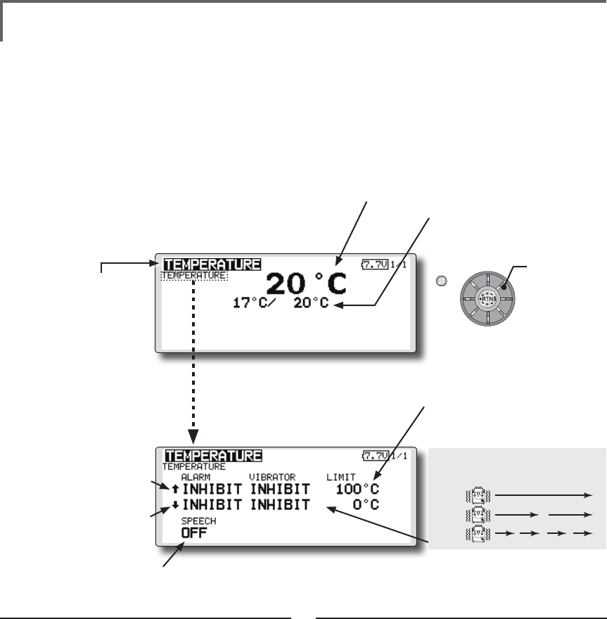
TELEMETRY : TEMPERATURE Displaying data from the temperature
Temperature is a screen which displays/sets
up the temperature information from an optional
temperature sensor.
The temperature of the model (engine, motor,
battery, etc.) which is ying can be displayed.
If it becomes higher or lower than the setting an
alarm and/or vibration will alert you.
*Only receiver voltage can be used in FASSTest 12CH mode.
*The FASSTest 18CH mode can use all the telemetry
functions.
● Select [TEMPERATURE] in the TELEMETRY screen and access
the setup screen shown below by pushing the RTN button.
Scrolling
● Moving cursor
● Temperature
● The maximum and the minimum when
powering ON are shown. It will be preset,
if a cursor is moved to this place and the
RTN button is pushed for 1 second.
● ↓ A downward arrow
will show that an alarm
will sound when the
temperature drops below
the set value.
● ↑ An upward arrow will show
that an alarm will sound
when the temperature rises
above the set value.
Alert set : Hot warning
1. Move the cursor to the ↑ALARM item, and
it chooses from BUZZER, VOICE, INHIBIT, and
pushes RTN.
2. When not operating vibrator, it is "VIBRATOR"
to INHIBIT. TYPE1-3 will be chosen if it is made
to operate.
3. Move the cursor to the LIMIT [ ℃] item and
push the RTN button to switch to the data
input mode.
4. Ajust the rate by scrolling the edit dial.
Initial value: 100℃
Adjustment range: 0℃~200℃
(↑LIMIT ≧ ↓LIMIT)
*When the RTN button is pushed for one second, the rate is
reset to the initial value.
5. Push the RTN button. (To terminate the input
and return to the original state, push the
Home/Exit button.)
Alert set : Low-temperature warning
1. Move the cursor to the ↓ALARM item, and
it chooses from BUZZER, VOICE, INHIBIT, and
pushes RTN.
2. When not operating vibrator, it is "VIBRATOR"
to INHIBIT. TYPE1-3 will be chosen if it is made
to operate.
3. Move the cursor to the LIMIT [ ℃] item and
push the RTN button to switch to the data
input mode.
4. Ajust the rate by scrolling the edit dial.
Initial value: 0℃
Adjustment range: 0℃~200℃
(↑LIMIT ≧ ↓LIMIT)
*When the RTN button is pushed for one second, the rate is
reset to the initial value.
5. Push the RTN button. (To terminate the input
and return to the original state, push the
Home/Exit button.)
*A temperature sensor must be installed in the aircraft.
●Select [TEMPERATURE](small font
display) in the TEMPERATURE screen
and access the setup screen shown
below by pushing the RTN button.
● The ON/OFF switch of SPEECH is chosen.
●A setup of the temperature on
which the alarm operates.
TYPE 1
TYPE 2
TYPE 3
"VIBRATOR" type
If the following types are selected, the transmitter
will vibrate during the warning.
73
<Functions of Linkage Menu>
S1
<Edit dial>
● Select the function name
and return to the Linkage
menu by pushing the RTN
button or pushing the
Home/Exit button.
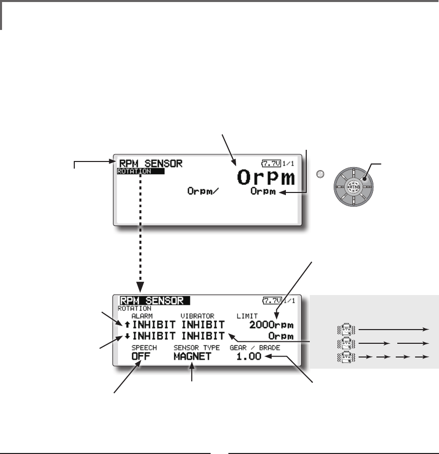
TELEMETRY : RPM SENSOR Displaying data from the RPM
RPM sensor is a screen which displays / sets up
the rotation information from an optional RPM
sensor.
The rotation of the model (engine, motor, etc.)
which is ying can be shown.
If it becomes higher or lower than the setting an
alarm and/or vibration will alert you.
*Only receiver voltage can be used in FASSTest 12CH mode.
*The FASSTest 18CH mode can use all the telemetry
functions.
Alarm set : Over rotations
1. Move the cursor to the ↑ALARM item, and
it chooses from BUZZER, VOICE, INHIBIT, and
pushes RTN.
2. When not operating vibrator, it is "VIBRATOR"
to INHIBIT. TYPE1-3 will be chosen if it is made
to operate.
3. Move the cursor to the LIMIT [2,000rpm] item
and push the RTN button to switch to the
data input mode.
4. Ajust the rate by scrolling the edit dial.
Initial value: 2,000rpm
Adjustment range: 0rpm~150,000rpm
(↑LIMIT ≧ ↓LIMIT)
*When the RTN button is pushed for one second, the rate is
reset to the initial value.
5. Push the RTN button. (To terminate the input
and return to the original state, push the
Home/Exit button.)
Alarm set : Under rotations
1. Move the cursor to the ↓ALARM item, and
it chooses from BUZZER, VOICE, INHIBIT, and
pushes RTN.
2. When not operating vibrator, it is "VIBRATOR"
to INHIBIT. TYPE1-3 will be chosen if it is made
to operate.
3. Move the cursor to the LIMIT [0rpm] item and
push the RTN button to switch to the data
input mode.
4. Ajust the rate by scrolling the edit dial.
Initial value: 0rpm
Adjustment range: 0rpm~150,000rpm
(↑LIMIT ≧ ↓LIMIT)
*When the RTN button is pushed for one second, the rate is
reset to the initial value.
5. Push the RTN button. (To terminate the input
and return to the original state, push the
Home/Exit button.)
*A RPM sensor must be installed in the aircraft.
● The maximum and the minimum when
powering ON are shown. It will be preset,
if a cursor is moved to this place and the
RTN button is pushed for 1 second.
●A setup of the revolution on
which the alarm operates.
● Select [RPM sensor] in the TELEMETRY screen
and access the setup screen shown below
by pushing the RTN button.
Scrolling
● Moving cursor
● RPM
●"MAGNET" or "OPTICS" is set
according to the sensor
you use.
SBS-01RM : MAGNET
SBS-01RO : OPTICS
● ↓A downward arrow
indicates that the alarm
will sound when the RPM
falls below the set value.
● ↑An upward arrow
indicates that the alarm
will sound when the RPM
rises above the set value.
● In "MAGNET", the gear ratio of your
engine (motor) you are using is
entered.
● In "OPTICS", the number of blades
of the propeller ( r o t o r ) your
model is entered.
●Select [ROTATION](small font display)
in the RPM sensor screen and
access the setup screen shown
below by pushing the RTN button.
● The ON/OFF switch of
SPEECH is chosen.
TYPE 1
TYPE 2
TYPE 3
"VIBRATOR" type
If the following types are selected, the transmitter
will vibrate during the warning.
74 <Functions of Linkage Menu>
S1
<Edit dial>
● Select the function name
and return to the Linkage
menu by pushing the RTN
button or pushing the
Home/Exit button.
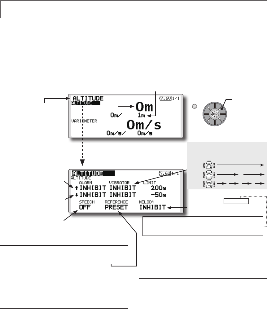
TELEMETRY : ALTITUDE Displaying data from the altitude
ALTITUDE is a screen which displays / sets up the
altitude information from an optional altitude sensor or GPS
sensor. The altitude of the model which is flying can be
known. If it becomes higher (low) than preset altitude, you
can be told by alarm. To show warning by vibration can also
be chosen. Data when a power supply is turned on shall be
0 m, and it displays the altitude which changed from there.
Even if the altitude of an aireld is high, that shall be 0 m
and the altitude difference from an airfield is displayed.
This sensor calculates the altitude from atmospheric
Pushure. Atmospheric Pushure will get lower as you go up
in altitude, using this the sensor will estimate the altitude.
Please understand that an exact advanced display cannot
be performed if atmospheric Pushure changes in a weather
situation.
*Only receiver voltage can be used in FASSTest 12CH mode.
*The FASSTest 18CH mode can use all the telemetry functions.
● Select [ALTITUDE] in the TELEMETRY screen and
access the setup screen shown below by
pushing the RTN button.
Scrolling
● Moving cursor
● Altitude
● ↓ A downward arrow
indicates the alarm will
sound when the altitude
reaches below your set
value.
● ↑ An upward arrow
indicates the alarm will
sound when the altitude
reaches above your set
value.
First, the set of a reference is required.
1. The model and transmitter to which the
altitude sensor was connected are turned on.
2. Move the cursor to the [PRESET] of
"REFERENCE" item.
3. Push the RTN button is pushed for 1 second.
(To terminate the input and return to the original
state, push the Home/Exit button.)
*Atmospheric Pushure is changed according to the weather also
at the same aireld. You should preset before a ight.
Alarm set : High side
1. Move the cursor to the ↑ALARM item, and
it chooses from BUZZER, VOICE, INHIBIT, and
pushes RTN.
2. When not operating vibrator, it is "VIBRATOR"
to INHIBIT. TYPE1-3 will be chosen if it is made
to operate.
3. Move the cursor to the LIMIT [m] item and
push the RTN button to switch to the data
input mode.
4. Ajust the rate by scrolling the edit dial.
Initial value: 200m
Adjustment range-500m~+3,000m
(↑LIMIT ≧ ↓LIMIT)
*When the RTN button is pushed for one second, the rate is
reset to the initial value.
5. Push the RTN button. (To terminate the input
and return to the original state, push the
Home/Exit button.)
Alarm set : Low side
1. Move the cursor to the ↓ALARM item, and
it chooses from BUZZER, VOICE, INHIBIT, and
pushes RTN.
2. When not operating vibrator, it is "VIBRATOR"
to INHIBIT. TYPE1-3 will be chosen if it is made
to operate.
3. Move the cursor to the LIMIT [m] item and
push the RTN button to switch to the data
input mode.
4. Ajust the rate by scrolling the edit dial.
Initial value: -50m
Adjustment range-500m~+3,000m
(↑LIMIT ≧ ↓LIMIT)
*When the RTN button is pushed for one second, the rate is
reset to the initial value.
5. Push the RTN button. (To terminate the input
and return to the original state, push the
Home/Exit button.)
*An altitude sensor or GPS sensor must be installed in the aircraft.
●Select [ALTITUDE](small font display) in the
TEMPERATURE screen and access the setup
screen shown below by pushing the RTN
button.
● The maximum and the minimum when powering ON are
shown. It will be preset, if a cursor is moved to this place and
the RTN button is pushed for 1 second.
●The ON/OFF switch of SPEECH
is chosen.
●If this is set to MODE1-4, a rise
and dive are told by a different
melody.
MODE1: Little rise/dive→Melody changes (sensitively)
MODE4: Big rise/dive→Melody changes (insensible)
. . .
TYPE 1
TYPE 2
TYPE 3
"VIBRATOR" type
If the following types are selected, the
transmitter will vibrate during the warning.
75
<Functions of Linkage Menu>
S1
<Edit dial>
● Select the function name
and return to the Linkage
menu by pushing the RTN
button or pushing the
Home/Exit button.
● Select [ALTITUDE] in the TELEMETRY screen and
access the setup screen shown below by
pushing the RTN button.
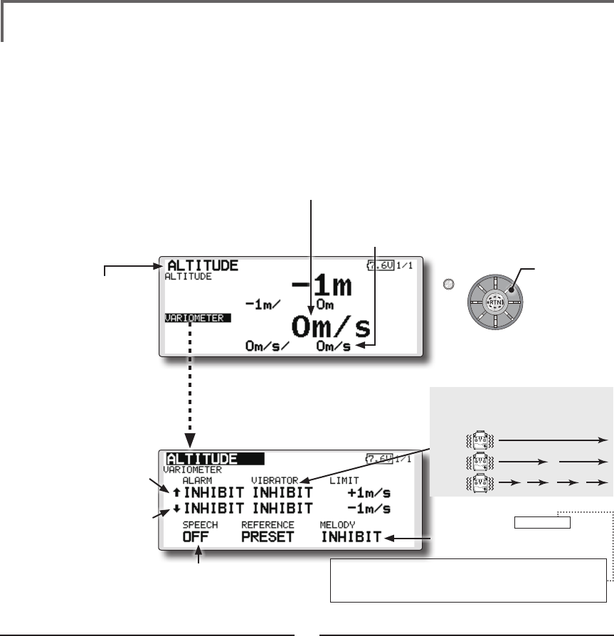
TELEMETRY : ALTITUDE [VARIOMETER] Displaying data from the
variometer
VARIO is a screen which displays / sets up the
variometer information from an optional altitude
sensor or GPS sensor.
The variometer of the model which is ying can
be known.
If it becomes higher or lower than the setting an
alarm and/or vibration will alert you.
To ensure that the pilot is aware as to the model's
status, the FMT-03 incorporates a different melody
for ascent and descent. Additionally, depending
upon the rate of climb or descent, the tones vary to
indicate whether or not the airplane is climbing or
descending at a rapid rate.
*Only receiver voltage can be used in FASSTest 12CH mode.
*The FASSTest 18CH mode can use all the telemetry
functions.
Alert set : Rise side
1. Move the cursor to the ↑ALARM item, and
it chooses from BUZZER, VOICE, INHIBIT, and
pushes RTN.
2. When not operating vibrator, it is "VIBRATOR"
to INHIBIT. TYPE1-3 will be chosen if it is made
to operate.
3. Move the cursor to the LIMIT [m/s] item and
push the RTN button to switch to the data
input mode.
4. Ajust the rate by scrolling the edit dial.
Initial value: +1m
Adjustment range -50m/s~+50m/s
(↑LIMIT ≧ ↓LIMIT)
*When the RTN button is pushed for one second, the rate is
reset to the initial value.
5. Push the RTN button. (To terminate the input
and return to the original state, push the
Home/Exit button.)
Alert set : Dive side
1. Move the cursor to the ↓ALARM item, and
it chooses from BUZZER, VOICE, INHIBIT, and
pushes RTN.
2. When not operating vibrator, it is "VIBRATOR"
to INHIBIT. TYPE1-3 will be chosen if it is made
to operate.
3. Move the cursor to the LIMIT [m/s] item and
push the RTN button to switch to the data
input mode.
4. Ajust the rate by scrolling the edit dial.
Initial value: -1m
Adjustment range -50m/s~+50m/s
(↑LIMIT ≧ ↓LIMIT)
*When the RTN button is pushed for one second, the rate is
reset to the initial value.
5. Push the RTN button. (To terminate the input
and return to the original state, push the
Home/Exit button.)
*An altitude sensor or GPS sensor must be installed in the aircraft.
●If this is set to MODE1-4, a rise
and dive are told by a different
melody.
MODE1: Little rise/dive→Melody changes (sensitively)
MODE4: Big rise/dive→Melody changes (insensible)
. . .
Scrolling
● Moving cursor
● ↓ A downward arrow
indicates the alarm will
sound when the variomete
reaches below your set
value.
● ↑ An upward arrow indicates
the alarm will sound when
the variometer reaches
above your set value.
TYPE 1
TYPE 2
TYPE 3
"VIBRATOR" type
If the following types are selected, the
transmitter will vibrate during the warning.
●Select [VARIOMETER](small font
display) in the TEMPERATURE screen
and access the setup screen shown
below by pushing the RTN button.
● The maximum and the minimum when powering ON
are shown. It will be preset, if a cursor is moved to this
place and the RTN button is pushed for 1 second.
● Variometer
●The ON/OFF switch of
SPEECH is chosen.
76 <Functions of Linkage Menu>
S1
<Edit dial>
● Select the function name
and return to the Linkage
menu by pushing the RTN
button or pushing the
Home/Exit button.
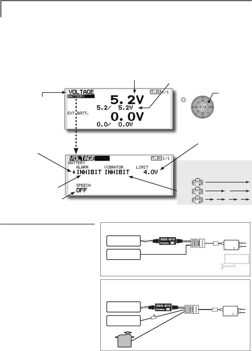
In this screen, the battery voltage is displayed.
In order to use this function, it is necessary to
connect External voltage connector of FMR-03 ⇔
SBS-01V ⇔ Battery
SBS-01V measures two batteries. The power
battery connected to two lines is displayed on EXT-
VOLT. The battery for receivers connected to 3P
lines is displayed here.
*Only receiver voltage can be used in FASSTest 12CH mode.
*The FASSTest 18CH mode can use all the telemetry
functions.
*SBS-01V must be installed in the aircraft.
<Two examples of wiring are shown >
*Refer to the manual of SBS-01V for the details of wiring.
Drive battery
(EXT Battery)
Switch
Power supplies
for servos
Another
power
supply Hub
S.BUS2
servos
Drive battery are measured (SBS-01V use)
Drive battery and power supplies for servos are measured (SBS-01V use)
●Battery voltage measurement for receivers [FMR-03 use]
●Battery voltage measurement for receivers [SBS-01V use]
●The drive battery is measured in an EXT line [SBS-01V use]
●Battery voltage measurement for receivers [FMR-01 use]
●The drive battery is measured in an EXT line [SBS-01V use]
●The voltage for servos is measured in a power supply line [SBS-01V use]
Normal Line
EXT Line
EXT Line
*SBS-01V measures two voltage. One corresponds to high voltages, such as a drive battery,
with an EXT line. Another is a normal line and is measurement of the battery for receivers of a
line connected to 3P connector, or the battery for servos.
*The same
receiver battery
Receiver battery
Drive battery
(EXT Battery)
TELEMETRY : VOLTAGE [BATTERY] Displaying data from the battery
voltage
●Select [VOLTAGE] in the TELEMETRY screen and access the
setup screen shown below by pushing the RTN button.
●Select [BATTERY] in the VOLTAGE screen and
access the setup screen shown below by
pushing the RTN button.
●A setup of the voltage
on which the alarm
operates.
Scrolling
● Moving cursor
●Battery
voltage
●The maximum and the minimum when
powering ON are shown. It will be preset, if
a cursor is moved to this place and the RTN
button is pushed for 1 second.
●↓The "down" arrow will indicate
that an alarm will sound when
the voltage drops to below the
setting.
●ALARM is chosen from
BUZZER, VOICE, and
INHIBIT.
●The ON/OFF switch of SPEECH is chosen.
Alarm set
1. Move the cursor to the ↓ALARM
item, and it chooses from BUZZER,
VOICE, INHIBIT, and pushes RTN.
2. When not operating vibrator, it is
"VIBRATOR" to INHIBIT. TYPE1-3 will
be chosen if it is made to operate.
3. Move the cursor to the LIMIT [4.0V]
item and push the RTN button to
switch to the data input mode.
4. Ajust the rate by scrolling the edit
dial.
Initial value: 4.0V
Adjustment range: 0.0V-100.0V
*When the RTN button is pushed for one second,
the rate is reset to the initial value.
5. Push the RTN button. (To terminate
the input and return to the original
state, push the Home/Exit button.)
TYPE 1
TYPE 2
TYPE 3
"VIBRATOR" type
If the following types are selected, the
transmitter will vibrate during the warning.
77
<Functions of Linkage Menu>
S1
<Edit dial>
● Select the function name
and return to the Linkage
menu by pushing the RTN
button or pushing the
Home/Exit button.
Alarm set
1. Move the cursor to the ↓ALARM item, and
it chooses from BUZZER, VOICE, and INHIBIT,
and pushes RTN.
2. When not operating vibrator, it is "VIBRATOR"
to INHIBIT. TYPE1-3 will be chosen if it is made
to operate.
3. Move the cursor to the LIMIT [4.0V] item and
push the RTN button to switch to the data
input mode.
4. Ajust the rate by scrolling the edit dial.
Initial value: 4.0V
Adjustment range: 0.0V~100.0V
*When the RTN button is pushed for one second, the rate is
reset to the initial value.
5. Push the RTN button. (To terminate the input
and return to the original state, push the
Home/Exit button.)
TELEMETRY : VOLTAGE [EXT-VOLT] Displaying data from the EXT
battery voltage port
In this screen, the EXT battery voltage is
displayed. In order to use this function, it is
necessary to connect External voltage connector of
FMR-03 ⇔ SBS-01V ⇔ Battery
SBS-01V measures two batteries. The power
battery connected to two lines is displayed on EXT-
VOLT.
*Only receiver voltage will be received in the FASSTest 12CH
mode.
*The FASSTest 18CH mode will display all telemetry data.
*SBS-01V must be installed in the aircraft.
● Select [VOLTAGE] in the TELEMETRY screen
and access the setup screen shown below by
pushing the RTN button.
● Select [EXT BATT.] in the RECEIVER screen
and access the setup screen shown
below by pushing the RTN button.
●A setup of the voltage on
which the alarm operates.
Scrolling
● Moving cursor
● EXT battery voltage ● The maximum and the minimum when
powering ON are shown. It will be preset,
if a cursor is moved to this place and the
RTN button is pushed for 1 second.
● ↓The "down" arrow will
indicate that an alarm will
sound when the voltage
drops to below the setting.
● ALARM is chosen from
BUZZER, VOICE, and
INHIBIT.
● The ON/OFF switch of SPEECH is chosen.
TYPE 1
TYPE 2
TYPE 3
"VIBRATOR" type
If the following types are selected, the
transmitter will vibrate during the warning.
78 <Functions of Linkage Menu>
S1
<Edit dial>
● Select the function name
and return to the Linkage
menu by pushing the RTN
button or pushing the
Home/Exit button.
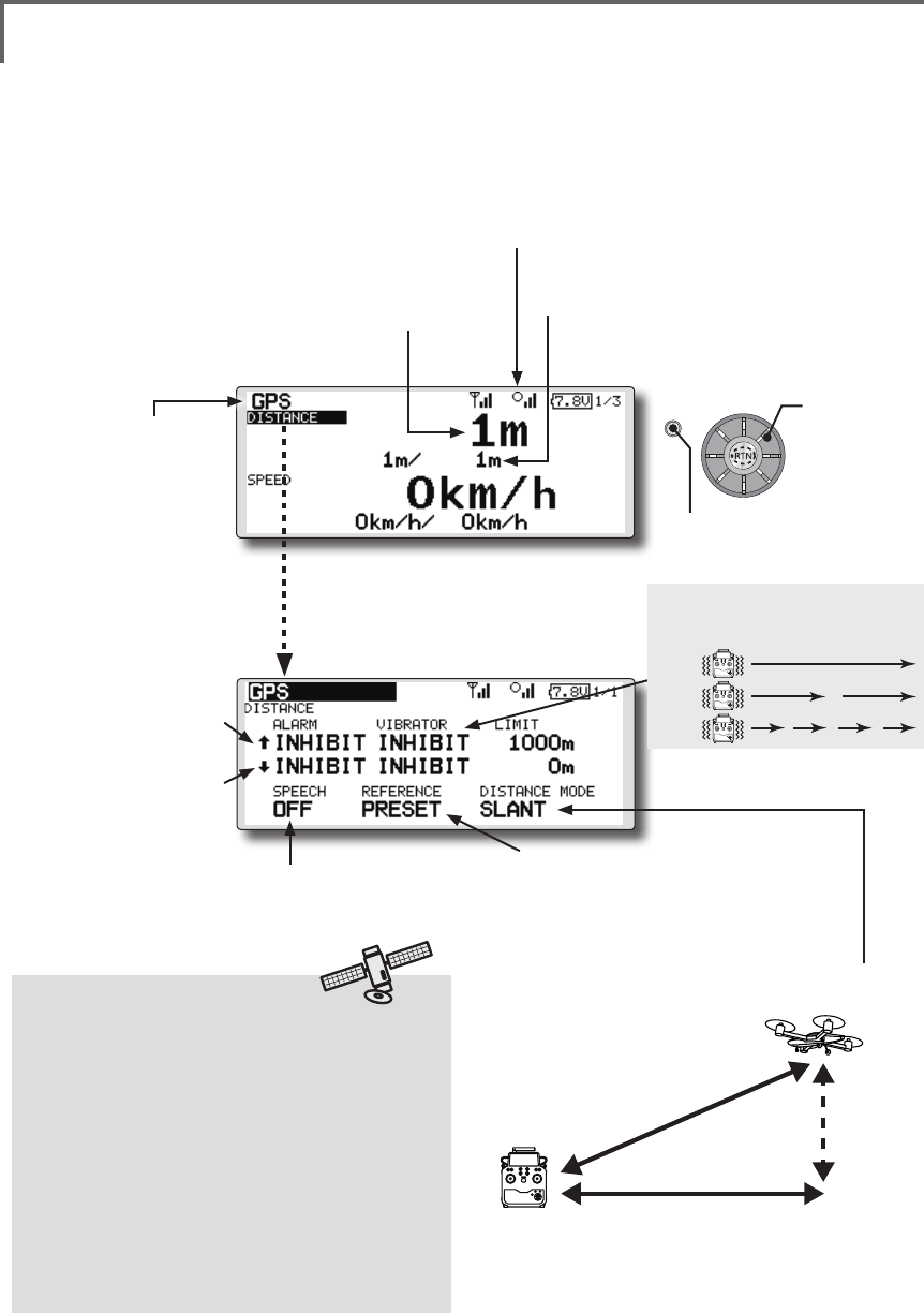
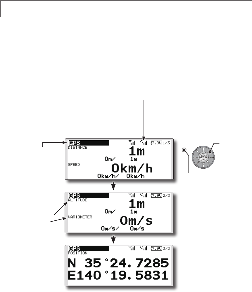
TELEMETRY : GPS [DISTANCE] Displaying data from the Distance Screen
The Distance screen displays and sets altitude
data from an SBS-01G GPS Sensor (sold
separately), and allows the distance to the airborne
aircraft to be read by the transmitter. When the
aircraft flies inside or outside the set distance an
alarm and vibration alerts the pilot.
*The GPS sensor is necessary, and is sold separately. Mount
and connect the sensor in accordance with the sensor
instruction manual.
*Only receiver voltage can be used in FASSTest 12CH mode.
*The FASSTest 18CH mode can use all the telemetry
functions.
*A GPS sensor must be installed in the aircraft.
●This indicates the receiving accuracy from a GPS
Satellite. When three bars are displayed, the GPS is
ready for use.
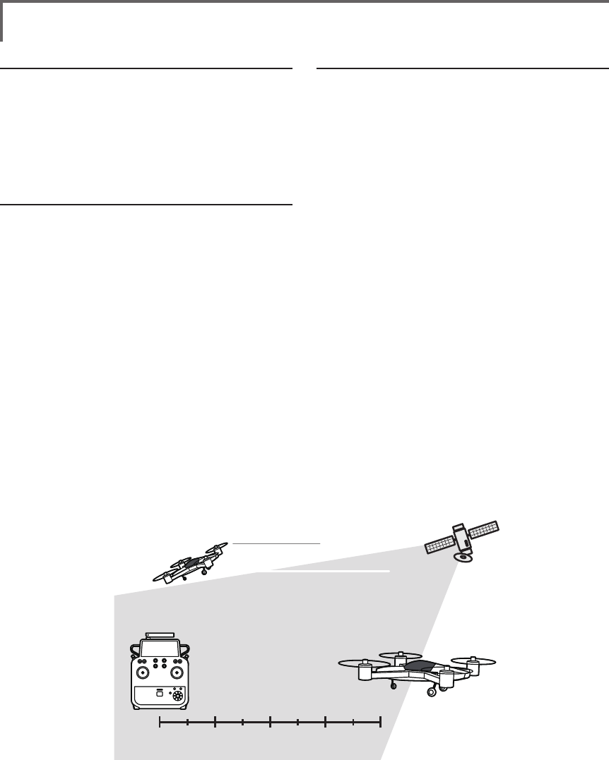
Surface
Altitude
Slant
●Altitude calculated as either straight line distance (slant)
or surface distance on a map can also be selected.
●Select <SLANT> <SURFACE> to “DISTANCE MODE”, scroll
either to the desired method and push the RTN button.
*Positioning time of GPS
When powered up, the SBS-01G begins to
acquire GPS satellite data. This process can
take several minutes. Please do not move the
model during this process. During acquisition,
the LED on the SBS-01G will blink green;
after the satellites signals have been acquired,
the LED will become solid green, and the GPS
signal strength display on the transmitter will
show three bars.
Moving the model before the satellites are fully
acquired will cause a delay in acquiring the
satellite signal.
● Select [GPS] in the TELEMETRY screen and
access the setup screen shown below by
pushing the RTN button.
Scrolling
● Moving cursor
● Distance
● ↓ A downward arrow
indicates the alarm will sound
when the distance reaches
below your set value.
● ↑ An upward arrow indicates
the alarm will sound when
the distance reaches above
your set value.
●Select [DISTANCE](small font display) in the
TEMPERATURE screen and access the setup
screen shown below by pushing the RTN
button.
● The maximum and the minimum when powering
ON are shown. It will be preset, if a cursor is
moved to this place and the RTN button is pushed
for 1 second.
●The ON/OFF switch of
SPEECH is chosen.
●Move the cursor to the [PRESET] of
"REFERENCE" item. Push the RTN button
is pushed for 1 second. Sets the current
aircraft position as the starting point.
TYPE 1
TYPE 2
TYPE 3
"VIBRATOR" type
If the following types are selected, the
transmitter will vibrate during the warning.
● Push the S1 button
to call next page.
79
<Functions of Linkage Menu>
First, setting the pointos of reference is required.
1. The model and transmitter on which the GPS
sensor is connected are turned on.
2. Move the cursor to the [PRESET] of
"REFERENCE" item.
3. Push the RTN button is pushed for 1 second.
(To terminate the input and return to the original
state, push the Home/Exit button.)
*Now, the position of the present model was set to 0 m.
Setting a "too far" alarm distance
1. Move the cursor to the ↑ALARM item, and
it chooses from BUZZER, VOICE, INHIBIT, and
pushes RTN.
2. When not operating vibrator, it is "VIBRATOR"
to INHIBIT. TYPE1-3 will be chosen if it is made
to operate.
3. Move the cursor to the LIMIT [m] item and
push the RTN button to switch to the data
input mode.
4. Ajust the rate by scrolling the edit dial.
Initial value: 1,000m
Adjustment range 0m~3,000m
(↑LIMIT ≧ ↓LIMIT)
*When the RTN button is pushed for one second, the rate is
reset to the initial value.
5. Push the RTN button. (To terminate the input
and return to the original state, push the
Home/Exit button.)
Setting a "too close" alarm distance
1. Move the cursor to the ↓ALARM item, and
it chooses from BUZZER, VOICE, INHIBIT, and
pushes RTN.
2. When not operating vibrator, it is "VIBRATOR"
to INHIBIT. TYPE1-3 will be chosen if it is made
to operate.
3. Move the cursor to the LIMIT [m] item and
push the RTN button to switch to the data
input mode.
4. Ajust the rate by scrolling the edit dial.
Initial value: 0m
Adjustment range 0m~3,000m
(↑LIMIT ≧ ↓LIMIT)
*When the RTN button is pushed for one second, the rate is
reset to the initial value.
5. Push the RTN button. (To terminate the input
and return to the original state, push the
Home/Exit button.)
Distance
Speed
position
80 <Functions of Linkage Menu>
S1
<Edit dial>
● Select the function name
and return to the Linkage
menu by pushing the RTN
button or pushing the
Home/Exit button.
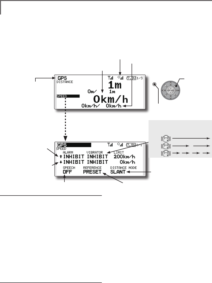
TELEMETRY : GPS [SPEED] Displaying data from the speed
The speed screen displays and sets the speed data from an
SBS-01G (GPS sensor) sold separately.
The speed of the aircraft during ight can be displayed.
After flight, the maximum speed during flight can be
viewed. Because this speed is based on position data from
a GPS satellite, the ground speed is displayed instead of
air speed. Consequently, with a head wind, the displayed
speed decreases and with a tail wind, the displayed speed
increases.
*The GPS sensor is necessary, and is sold separately. Mount and
connect the sensor in accordance with the sensor instruction manual.
*Only receiver voltage can be used in FASSTest 12CH mode.
*The FASSTest 18CH mode can use all the telemetry functions.
*A GPS sensor must be installed in the aircraft.
●This indicates the receiving accuracy from a
GPS Satellite. When three bars are displayed,
the GPS is ready for use.
● Select [GPS] in the TELEMETRY screen and
access the setup screen shown below by
pushing the RTN button.
Scrolling
● Moving cursor
● Speed
● ↓ A downward arrow
indicates the alarm will sound
when the speed reaches
below your set value.
● ↑ An upward arrow indicates
the alarm will sound when
the speed reaches above
your set value.
●Select [SPEED](small font display) in the
TEMPERATURE screen and access the setup
screen shown below by pushing the RTN
button.
● The maximum and the minimum when powering ON are
shown. It will be preset, if a cursor is moved to this place and
the RTN button is pushed for 1 second.
●The ON/OFF switch of
SPEECH is chosen.
●It links with the "DISTACE"
display.
●Pushing [PRESET] sets the current aircraft
position as the starting point.
Alarm setting when speed increases
1. Move the cursor to the ↑ALARM item, and it
chooses from BUZZER, VOICE, INHIBIT, and pushes
RTN.
2. When not operating vibrator, it is "VIBRATOR"
to INHIBIT. TYPE1-3 will be chosen if it is made to
operate.
3. Move the cursor to the LIMIT [km/h] item and push
the RTN button to switch to the data input mode.
4. Ajust the rate by scrolling the edit dial.
Initial value: 200km/h
Adjustment range 0km/h-500km/h
(↑LIMIT ≧ ↓LIMIT)
*When the RTN button is pushed for one second, the rate is
reset to the initial value.
5. Push the RTN button. (To terminate the input and
return to the original state, push the Home/Exit
button.)
Alarm setting when speed decreases
1. Move the cursor to the ↓ALARM item, and it
chooses from BUZZER, VOICE, INHIBIT, and pushes
RTN.
2. When not operating vibrator, it is "VIBRATOR"
to INHIBIT. TYPE1-3 will be chosen if it is made to
operate.
3. Move the cursor to the LIMIT [km/h] item and push
the RTN button to switch to the data input mode.
4. Ajust the rate by scrolling the edit dial.
Initial value: 0km/h
Adjustment range 0km/h-500km/h
(↑LIMIT ≧ ↓LIMIT)
*When the RTN button is pushed for one second, the rate is
reset to the initial value.
5. Push the RTN button. (To terminate the input and
return to the original state, push the Home/Exit
button.)
*Speed alarm precaution
Since the GPS speed sensor displays the ground speed, it
cannot be used as a stall alarm. For example, an aircraft that
stalls at 50km/h will stall if the tailwind is 5km/h or greater
even through 55km/h is displayed by ground speed. In
addition, with an aircraft that will fail in midight at 400km/
h at an over-speed alarm, when the headwind reaches 30km/h
the airplane will fail in midair due to over speeding even at a
ground speed of 370km/h.
TYPE 1
TYPE 2
TYPE 3
"VIBRATOR" type
If the following types are selected, the
transmitter will vibrate during the warning.
● Push the S1 button
to call next page.
81
<Functions of Linkage Menu>
S1
● Select the function name
and return to the Linkage
menu by pushing the RTN
button or pushing the
Home/Exit button.
<Edit dial>
TELEMETRY : GPS [ALTITUDE, VARIOMETER, POSITION]
The altitude, variometer, position screen displays
and sets the data from an SBS-01G (GPS sensor)
sold separately.
*The GPS sensor is necessary, and is sold separately. Mount
and connect the sensor in accordance with the sensor
instruction manual.
*Only receiver voltage can be used in FASSTest 12CH mode.
*The FASSTest 18CH mode can use all the telemetry
functions.
*A GPS sensor must be installed in the aircraft.
● Push S1 button to advance to next page.
●This indicates the receiving accuracy from a GPS
Satellite. When three bars are displayed, the GPS is
ready for use.
● Select [GPS] in the TELEMETRY screen and access the
setup screen shown below by pushing the RTN button.
● Refer to the former
page for a setup
about ALTITUDE and
VARIOMETER.
● Push S1 button to advance to next page.
● The position of the present model is displayed.
Scrolling
● Moving cursor
● Push the S1 button
to call next page.
82 <Functions of Linkage Menu>
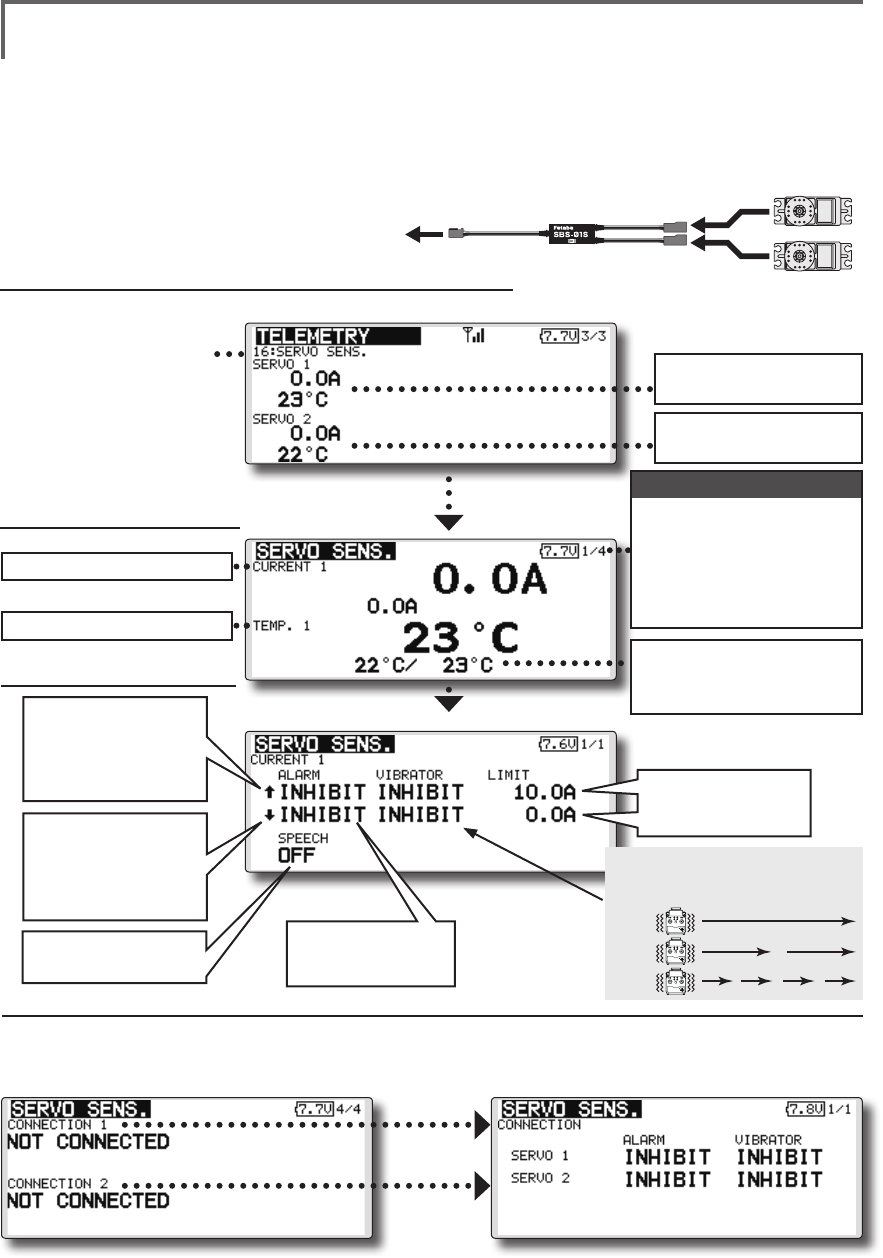
TELEMETRY : Servo sensor [Current] [Temperature] [Angle]
The SBS-01S can monitor and display the
in-flight current, operating angle, and internal
temperature of up to two S.BUS2 servos.
If you forget to connect the servo wiring during
fuselage assembly, or the servo was disconnected,
an alarm can be activated at the transmitter.
*Only receiver voltage will be received in the FASSTest 12CH
mode.
*The FASSTest 18CH mode will display all telemetry data.
*SBS-01S must be installed in the aircraft.
SBS-01S
to
S.BUS2
port
S.BUS servo
Servo sensor screen
Calling of a servo sensor screen.
①[Linkage menu]→[Telemetry]
②Select [SERVO SENS]
in the TELEMETRY
screen and access
the next screen
shown below by
pushing the RTN
button.
The current and the
temperature of servo 1
To current setup screen
To temperature setup screen
The current and the
temperature of servo 2
1/4 : Servo1: Current・Temp
2/4 : Servo1: Angle
Servo2: Current
3/4 : Servo2: Temp・Angle
4/4 : Servo1・2 : Connect
Page
Max. and min. values since
the power was turned ON
will display.
Alarm setting
A setup of the
current on which
the alarm operates.
Alarm is chosen
from Buzzer, Voice,
and Inhibit.
The ON/OFF switch of
Speech is chosen.
↑ An upward arrow
indicates the alarm
will sound when the
current reaches
above your set value.
↓ A downward arrow
indicates the alarm
will sound when the
current reaches
below your set value. TYPE 1
TYPE 2
TYPE 3
"VIBRATOR" type
If the following types are selected, the
transmitter will vibrate during the warning.
Connect Alarm setting
When the Alarm or Vibrator options are
activated, the servo connection will display.
*This alarm and display is limited to the S.BUS servos connected to the servo sensors.
If you forget to connect the servo wiring during
fuselage assembly, or the servo was disconnected,
an alarm can be activated at the transmitter.
83
<Functions of Linkage Menu>
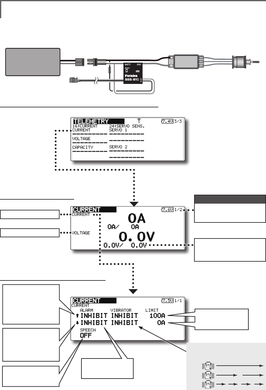
Current sensor screen
Alarm setting
Calling of a current sensor screen.
①[Linkage menu]→[Telemetry]
②Select [Current]
in the TELEMETRY
screen and
access the
next screen
shown below by
pushing the RTN
button.
A setup of the
current on which
the alarm operates.
Alarm is chosen
from Buzzer, Voice,
and Inhibit.
The ON/OFF switch
of Speech is
chosen.
↑ An upward arrow
indicates the alarm
will sound when the
current reaches
above your set
value.
↓ A downward arrow
indicates the alarm
will sound when the
current reaches
below your set value.
Page
Drive
Battery
SBS-01C
To Receiver
Motor
ESC
*Current sensor must be installed in the aircraft.
TELEMETRY : Current sensor [Current] [Voltage] [Capacity]
The SBS-01C has the capability of measuring
current, voltage and capacity (consumption) from
drive battery at the same time.
*Only receiver voltage will be received in the FASSTest 12CH
mode.
*The FASSTest 18CH mode will display all telemetry data.
1/2 : Current・Voltage
2/2 : Capacity
Max. and min. values since
the power was turned ON
will display.
TYPE 1
TYPE 2
TYPE 3
"VIBRATOR" type
If the following types are selected, the
transmitter will vibrate during the warning.
To current setup screen
To voltage setup screen
Page
84 <Functions of Linkage Menu>
S1
● Select the function name
and return to the Linkage
menu by pushing the RTN
button or pushing the
Home/Exit button.
<Edit dial>
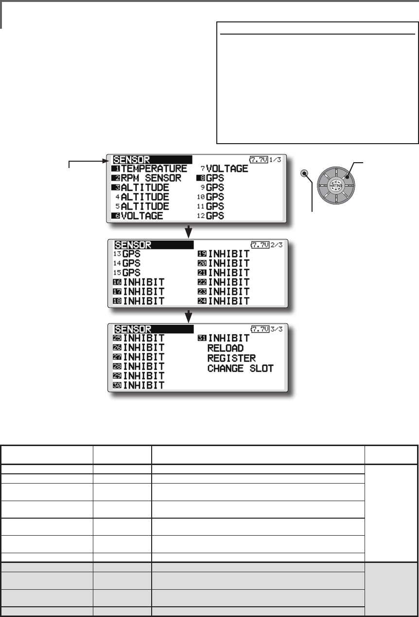
SENSOR Various telemetry sensors setting
This screen registers the telemetry sensors used
with the transmitter. When only one of a certain
type of sensor is used, this setting is unnecessary
and the sensor can be used by simply connecting it
to the S.BUS2 port of the transmitter.
When using 2 or more of the same kind of
sensor, they must be registered here.
● Select [SENSOR] in the Linkage menu and access the
setup screen shown below by pushing the RTN button.
● As shown in the table below, an altimeter requires 3 contiguous slots and a GPS sensor
requires 8 contiguous slots. In addition, since the GPS (SBS-01G) start slots are 8, 16, and 24.
<Assignable slot >*Altimeter, GPS, and other sensors that display a large amount of data require multiple slots.
*Depending on the type of sensor, the slot numbers that can be allocated may be limited.
[What is a slot?]
Servos are classified by CH, but sensors are
classied in units called “slot”. There are slots from #1
to #31.
Altitude sensors, GPS sensors and other data
sensor units may use multiple slots.
Using a sensor which uses two or more slots, the
required number of slots is automatically assigned by
setting up a start slot.
When 2 or more of the same kind of sensor are used,
the sensors themselves must allocate unused slots and
memorize that slot.
*3 slots of altitude sensor are used.
*8 slots of GPS sensor are used.
Sensor The required
number of slots The number which can be used as a start slot Selling area
TEMP (SBS-01T/TE) 1 slot 1 ~31
Global
RPM (SBS01RM/RO/RB) 1 slot 1 ~31
Voltage (SBS-01V) 2 slots 1,2,3,4,5,6,8,9,10,11,12,13,14,16,17,18,19,20,21,22,24,
25,26,27,28,29,30
Altitude (SBS-01A/02A) 3 slots 1,2,3,4,5,8,9,10,11,12,13,16,17,18,19,20,21,24,25,26,27,
28,29
Current (SBS-01C) 3 slots 1,2,3,4,5,8,9,10,11,12,13,16,17,18,19,20,21,24,25,26,27,
28,29
S.BUS Servo (SBS-01S) 6 slots 1,2,8,9,10,16,17,18,
24,25,26
GPS (SBS-01G) 8 slots 8,16,24
TEMP125-F1713 1 slot 1 ~31
Europe
VARIO-F1712 2 slots 1,2,3,4,5,6,8,9,10,11,12,13,14,16,17,18,19,20,21,22,24,
25,26,27,28,29,30
VARIO-F1672 2 slots 1,2,3,4,5,6,8,9,10,11,12,13,14,16,17,18,19,20,21,22,24,
25,26,27,28,29,30
GPS-F1675 8 slots 8,16,24
Scrolling
● Moving cursor
● Push S1 button to advance to next page.
● Push S1 button to advance to next page.
● Push the S1 button
to call next page.
85
<Functions of Linkage Menu>
● Select the function name
and return to the Linkage
menu by pushing the RTN
button or pushing the
Home/Exit button.
● Call page 3/3 by pushing the S1 button 2 times
from the [SENSOR] menu.
● Call page 3/3 by pushing the S1 button 2
times from the [SENSOR] menu.
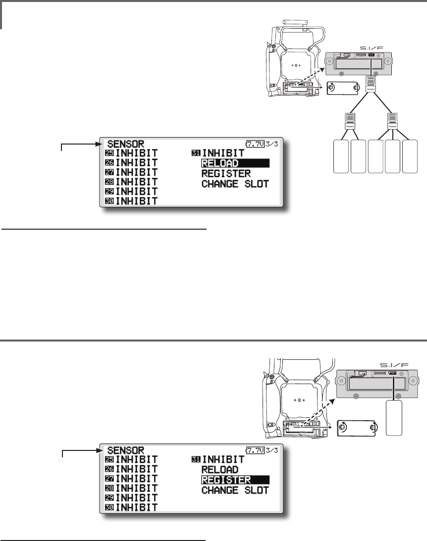
SENSOR : RELOAD
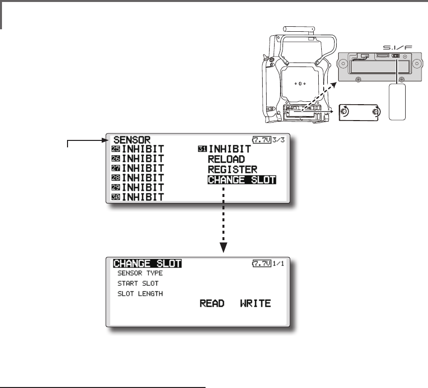
SENSOR : REGISTER
This page is set when using multiple telemetry sensors of the same type.
This page is set when using multiple telemetry sensors of the same type.
When using multiple sensors of the same type
the sensors must be registered in the transmitter.
Connect all the sensors to be used to the FMT-03 as
shown in the gure at the right and register them by
the following procedure. The ID of each sensor is
registered in the transmitter.
This function registers an additional sensor.
Connect the sensor as shown in the figure at the
right and register it by the following procedure.
The sensor ID is registered in the transmitter.
All the sensors to be used are connected.
SENSOR
SENSOR
3-way hub
or Y-harnesses
SENSOR
SENSOR
SENSOR
FMT-03
FMT-03
SENSOR
Reading all the sensors to be used
1. Connect all the sensors to be used to the
FMT-03 through a hub as shown in the gure
above.
2. Move the cursor to “RELOAD” on page 3/3 of
the [SENSOR] screen.
3. Push the RTN button.
All the sensors are registered and can be
used.
Additional sensor registration
1. Connect the sensor to be used to the FMT-03
through a hub as shown in the gure at the
right.
2. Move the cursor to “REGISTER” on page 3/3
of the <Sensor> screen.
3. Push the RTN button.
The sensor is registered and can be used.
*When the number of slots needed in registration is
insufcient, an error is displayed and registration cannot be
performed. Disable unused slots or perform the following
relocate.
*It is not necessary to carry out
multiple connection of the
battery like a T18MZ/T14SG.
(It will damage, if it connects.)
*It is not necessary to carry out
multiple connection of the
battery like a T18MZ/T14SG.
(It will damage, if it connects.)
● Select the function name
and return to the Linkage
menu by pushing the RTN
button or pushing the
Home/Exit button.
86 <Functions of Linkage Menu>
● Select the function name
and return to the Linkage
menu by pushing the RTN
button or pushing the
Home/Exit button.
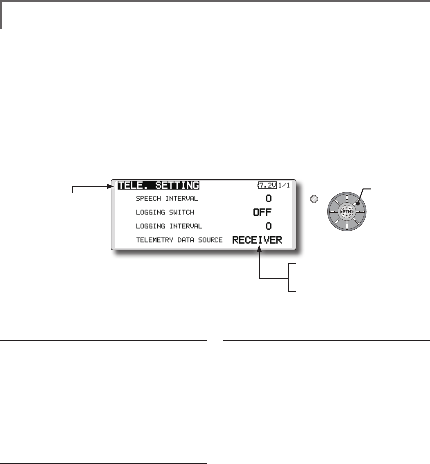
● Call page 3/3 by pushing the S1 button 2 times
from the [SENSOR] menu.
This procedure changes the slot number of one
registered sensor.
Sensor slot change
1. Connect the sensor to be changed to the
FMT-03 through a hub as shown in the gure
above.
2. Move the cursor to “CHANGE SLOT” on page
3/3 of the <Sensor> screen.
3. Push the RTN button. A sensor details screen
appears.
4. Move the cursor to “READ” and push the RTN
button.
5. The current start slot is displayed. Move the
cursor to the number of the start slot and
change it to the desired value.(Cannot be
set to a slot that cannot be allocated like the
table of all pages.)
6. Move the cursor to “WRITE” and push the RTN
button.
SENSOR : CHANGE SLOT
FMT-03
SENSOR
This page is set when using multiple telemetry sensors
of the same type.
● Select [CHANGE SLOT] in the SENSOR
screen and access the setup screen
shown below by pushing the RTN button.
*It is not necessary to carry out
multiple connection of the
battery like a T18MZ/T14SG.
(It will damage, if it connects.)
87
<Functions of Linkage Menu>
S1
<Edit dial>
● Select the function name
and return to the Linkage
menu by pushing the RTN
button or pushing the
Home/Exit button.
● RECEIVER : Data from a receiver is
recorded.
● TRAINER : Data from a trainer
connector is recorded.
*The special use for which usual isn't
used.
TELE. SETTING Speech interval set, data logging of telemetry.
The set of the speech interval of telemetry data,
and a switch setup for carrying out logging of the
telemetry data to micro SD card and a setup of a
logging interval are carried out.
Telemetry data can be checked with PC after a
ight.
*The software which displays the logging data of micro SD
card on PC has not been put on the market yet.
Speech interval setting
1. Select the Linkage Menu [TELE. SETTING] and
push the RTN button.
2. The TELE. SETTING setup screen is displayed.
3. Select numerical value beside[SPEECH
INTERVAL] and push the RTN button.
4. Ajust the time by scrolling the edit dial.
Initial value: 0
Adjustment range 0~30
5. Push the RTN button.
Logging switch setting
1. Select the Linkage Menu [TELE. SETTING] and
push the RTN button.
2. The TELE. SETTING setup screen is displayed.
3. Select [OFF] beside [LOGGING SWITCH] and
push the RTN button.
4. Move the cursor to the [SWITCH] item and
call the switch setup screen by pushing the
RTN button and select the switch and ON
direction.
(For a detailed description of the setting method, see [Switch
Setting Method] at the end of this manual.)
Logging interval setting
1. Select the Linkage Menu [TELE. SETTING] and
push the RTN button.
2. The TELE. SETTING setup screen is displayed.
3. Select numerical value beside [LOGGING
INTERVAL] and push the RTN button.
4. Ajust the time by scrolling the edit dial.
Initial value: 0
Adjustment range 0~100
5. Push the RTN button.
● Select [TELE. SETTING] at the linkage menu and call the
setup screen shown below by pushing the RTN button.
Scrolling
● Moving cursor
● Selecting mode
● Adjusting value
88 <Functions of Linkage Menu>
S1
<Edit dial>
● Select the function name
and return to the Linkage
menu by pushing the RTN
button or pushing the
Home/Exit button.
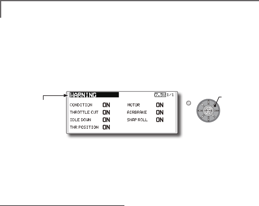
WARNING Mixing warning normal reset
The warning display at power ON can be turned
ON/OFF for each function. Use by setting functions
which may be dangerous if operated at power ON
to ON. Initial setting is all ON.
Warning ON/OFF setting
1. The settings can be changed individually.
When set to [OFF], a warning is not displayed
at power ON.
● Select [WARNING] at the linkage menu and call the setup screen
shown below by push the RTN button.
Scrolling
● Moving cursor
● Selecting mode

89
<Functions of Linkage Menu>
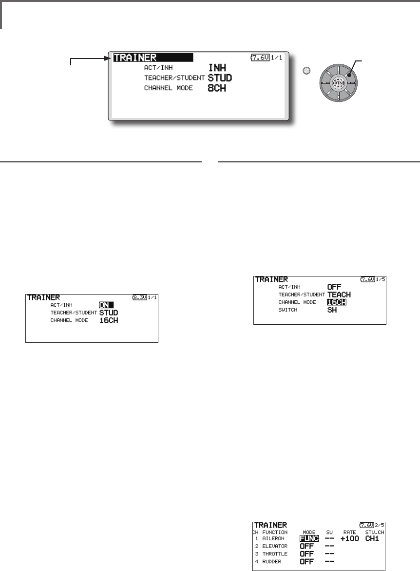
TRAINER Trainer system starting and setting
FMT-03 trainer system makes it possible for the
instructor to chose which channels and operation
modes that can be used in the students transmitter.
The function and rate of each channel can be
set, the training method can also be matched to
the student's skill level. Two FMT-03s must be
connected by an optional Trainer Cord, and the
Instructors’ transmitter should be programmed for
trainer operation, as described below.
When the Instructor activates the trainer switch,
the student has control of the aircraft (if MIX/
FUNC/NORM mode is turned on, the Instructor
can make corrections while the student has control).
When the switch is released the Instructor regains
control. This is very useful if the student gets the
aircraft into an undesirable situation.
● Setting data are stored to model data.
● Student rate can be adjusted at MIX/FUNC/
NORM mode.
● Activated student channels can be selected
by switches.
NOTE: This trainer system can be used in the
following manner;
1. With the FMT-03 transmitter and a
conventional transmitter, if the channel
order is different, it is necessary to match the
channel order before using this function.
You can select the channel of input data
from student's transmitter in the "FUNC" or
"MIX" mode.
2. A transmitter of anything but FMT-03 doesn't
correspond to this trainer system.
3. Be sure that all channels work correctly in
both transmitters before ying.
90 <Functions of Linkage Menu>
S1
● Select the function name
and return to the Linkage
menu by pushing the RTN
button or pushing the
Home/Exit button.
<Edit dial>
When using at the teacher side
1. Select the mode.
*When changing the mode, use the edit dial to move to the
item you want to change and push the RTN button to switch
to the data input mode and change the mode by turning the
edit dial to the left or right. The display blinks. Push the
RTN button to change the mode.
"TEACHER/STUDENT": Select [TEACH].
"ACT/INH": Enable operation by changing to
[OFF] or [ON].
"CHANNEL MODE": Select [16CH].
2. Select the trainer switch.
*When setting or changing the switch, use the edit dial to
move to the "SWITCH" item, call the switch setup screen by
pushing the RTN button and set the desired switch and ON/
OFF direction.
(See "Switch selection method" at the end of
this manual for selection method details.)
*The switch mode can also be selected when setting the
ON position on the switch setup screen. When [NORM] is
selected, normal ON/OFF operation is performed. When
[ALTERNATE] is selected, the trainer function is alternately
turned on and off each time the switch is operated. .
Note: The trainer function won’t be turned
on unless the Instructor's transmitter receives
signals from the student's transmitter. Be
sure to confirm this after connecting your
trainer cable.
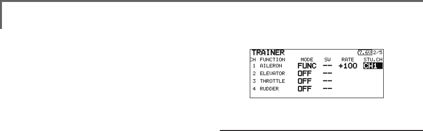
3. Select the operating mode for each channel.
● Select [TRAINER] at the system menu and call the setup
screen shown below by pushing the RTN button.
When using at the student side
1. Select the mode.
*When changing the mode, use the edit dial to move to the
item you want to change and push the RTN button to switch
to the data input mode and change the mode by turning the
edit dial to the left or right. The display blinks. Push the
RTN button to change the mode.
"TEACHER/STUDENT": Select [STUD] (student).
"ACT/INH": Enable operation by changing to
[ON].
"CHANNEL MODE": Select [16CH].
Note: In "student mode", only the teacher
side can turn on and off the power to the
student's transmitter. Keep the power switch
always at off position.
Scrolling
● Moving cursor
● Selecting mode
91
<Functions of Linkage Menu>
*Use the edit dial scrolling to move the cursor to the
"MODE" item of the channel you want to change and push
the RTN button to switch to the data input mode and change
the mode by turning the edit dial to the left or right. The
display blinks. Push the RTN button to change the mode.
"NORM": The model is controlled by signals
from the student transmitter.
"MIX" mode: The model is controlled by
signals from the teacher and student
transmitters. (Reset the student's model data
to the default condition.)
"FUNC" mode (function mode):
The model is controlled by signals from
the student transmitter with the teacher
AFR setting. (Reset the student's model data
to the default condition.)
"OFF": Only the teacher side operates.
*The setting above allows setting of the servo throw relative
to the amount of student side operation when [MIX] or
[FUNC] was selected.
When changing the rate, use the edit dial
scrolling to move the cursor to the [RATE]
item of the channel you want to change
and use the edit dial to adjust the rate.
Setting range: -100~+100
Initial value: +100
Push the RTN button to end adjustment and
return to the cursor move mode.
*When the RTN button is pushed for 1 second, the rate is
reset to the initial value.
3. Set the switch of each channel.
*When setting the switch at each channel, use the edit dial to
move to the "SW" item of the channel you want to change,
call the switch setup screen by pushing the RTN button, and
select the switch.
"--" : Always ON.
"SA"-"SH": The switch which enables student
side operation can be selected. (See "Switch
selection method" at the end of this manual
for selection method details.)
Trainer student channel setting function
Which channel of the signal from the student's
transmitter can be assigned as the instructor
functions input signal when "FUNC" or "MIX" was
set as the trainer function instructor's transmitter
mode setting can be set. This makes trainer
connection easy even when the instructor side and
student side channel assignment is different.
*When the instructor's transmitter mode is set to "NORM",
the signal of the same channel of the student's transmitter is
output as is. (The same as before.)
92 <Functions of Linkage Menu>
S1
<Edit dial>
● Select the function name
and return to the Linkage
menu by pushing the RTN
button or pushing the
Home/Exit button.
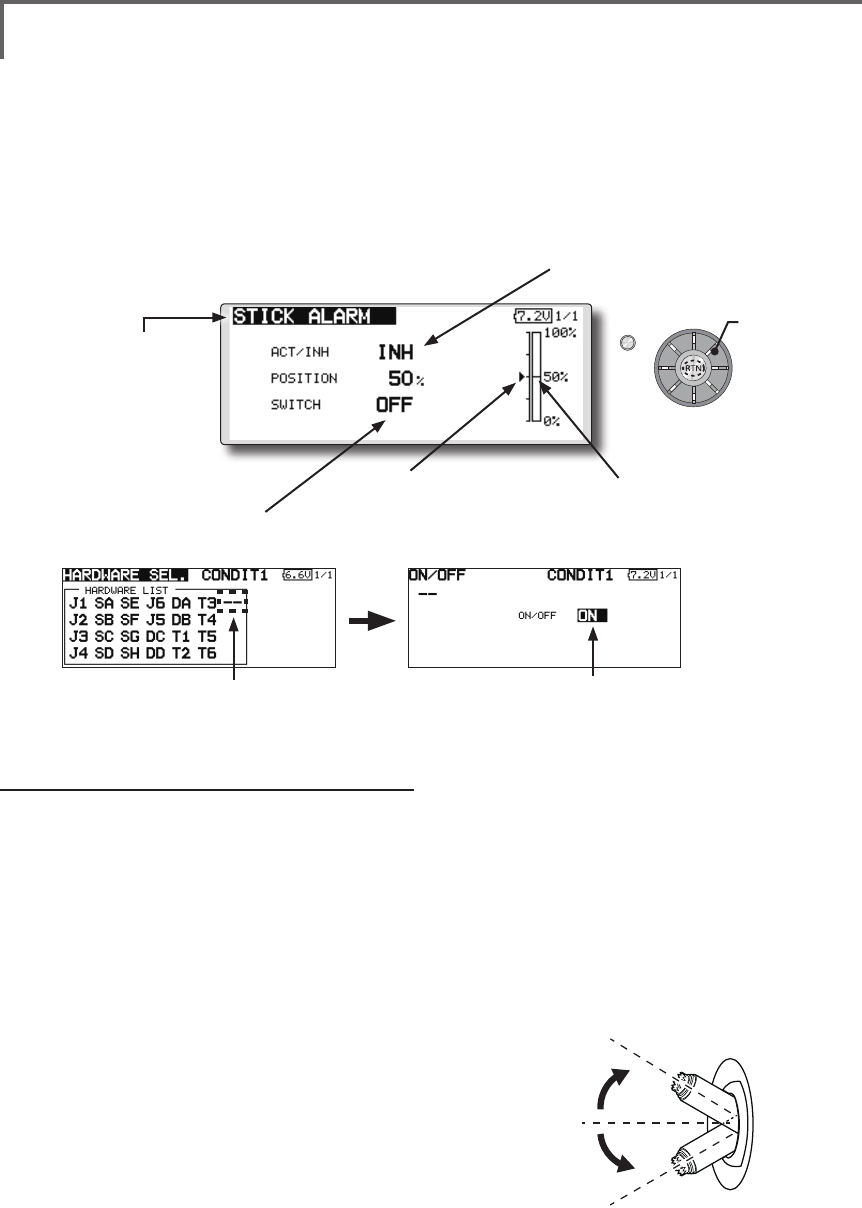
●When INH is selected, the function cannot
be used. When ON or OFF is selected, the
function is activated. ON and OFF changes
are linked to the switch.
●The current throttle stick
position.
●e.g., Always to make them stick alarm
in spite of switch.
●Select " -- " ●Select "ON"
● Stick alarm position.
STICK ALARM Throttle stick positional alarm
An alarm (single beep) can be sounded at the
specied throttle stick position.
*Alarm function ON/OFF can be set by switch.
Scrolling
● Moving cursor
● Selecting mode
● Adjusting value
100%
50%
0%
Stick alarm setting procedure
*Perform the following settings after using the edit dial to
move the cursor to the item you want to set.
1. Activate the function:
Move the cursor to the [ACT/INH] item and
push the RTN button to switch to the data
input mode.
Switch the blinking from "INH" to "ACT" by
turning the edit dial to the left and then push
the RTN button.
2. Switch setting:
Move the cursor to the [SWITCH] item, call
the switch setup screen by pushing the
RTN button, and select the switch and ON
direction.
(For a detailed description of the setting method, see [Switch
Setting Method] at the back of this manual.)
3. Alarm position setting:
Move the cursor to the [POSITION] item and
push the RTN button to switch to the data
input mode.
Adjust the alarm position operation by
turning the edit dial to the left or right.
Initial value: 50%
Adjustment range: 0%-100%
(When the RTN button is pushed for 1 second, the offset rate
is reset to the initial value.)
Push the RTN button to end adjustment and
return to the cursor move mode.
● Select [STICK ALARM] at the linkage menu and call the
setup screen shown below by pushing the RTN button.
93
<Functions of Linkage Menu>
S1
● Select the function name
and return to the Linkage
menu by pushing the RTN
button or pushing the
Home/Exit button.
<Edit dial>
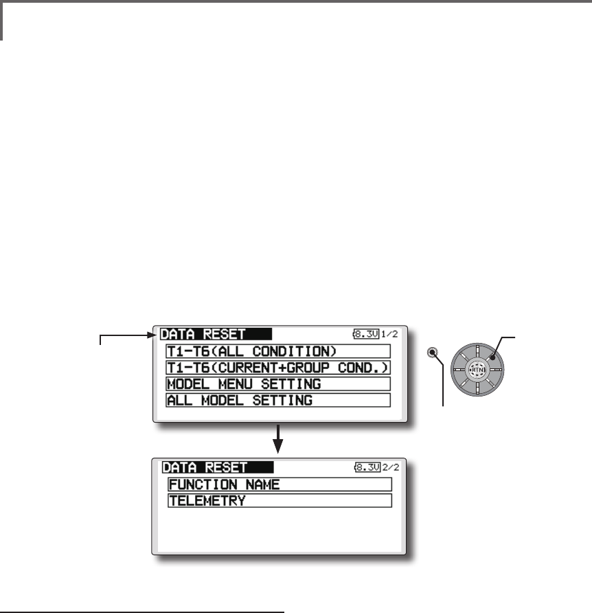
DATA RESET Model memory setting data reset. (by item)
This function is designed to allow you to reset
selected portions or all of the settings saved in
the active model memory. You may individually
choose to reset the following sets of data;
T1-T6:
Reset the digital trim setting.
*All the conditions, or the condition currently being displayed
(the entire group for group setting), can be selected.
*The trim step amount and trim rate are not reset.
Data resetting method
1. Move the cursor to the item you want to
reset and push the RTN button.
*A conrmation message appears.
2. Execute reset by pushing the RTN button
again. (Operate edit dial or S1 button to stop
resetting.)
[T1-T6 (ALL CONDITION)]: Resets only the T1-T6
(all conditions)
[T1-T6 (CURRNT+GROUP COND.)]: Resets only
the data of T1-T6 (condition in use and all the
conditions set to group mode)
[MODEL MENU SETTING]: Resets all the
functions in the model menu, except the
condition selection functions.
Model menu setting:
Resets all the functions in the Model menu
except condition select.
All model setting:
Resets all Linkage and Model menu functions
except for frequency, model select, and model type.
Function Name:
A function name is reset.
Telemetry:
Reset the telemetry setting.
[ALL MODEL SETTING]: Resets all the functions
in the linkage menu and model menu except
the frequency, model select, and model
type functions.
[FUNCTION NAME]: Resets only the function
name functions.
[TELEMETRY]: Resets only the telemetry
functions.
● Select [DATA RESET] at the linkage menu and call the
setup screen shown below by pushing the RTN button.
Scrolling
● Moving cursor
● Push S1 button to advance to next page.
● Push the S1 button
to call next page.
94 <Model Menu (Common Functions)>
●Selectthe[MODELMENU]
andreturnto the home
screenbypushingthe
RTNbuttonorpushingthe
Home/Exitbutton.
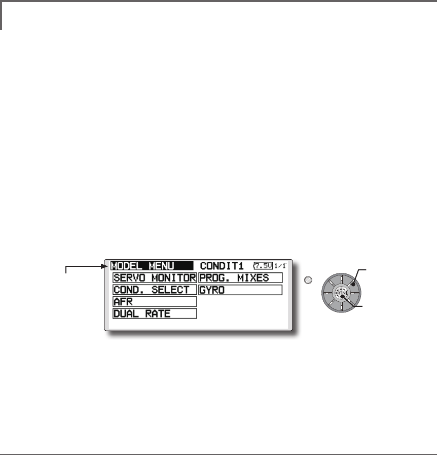
MODEL MENU (COMMON FUNCTIONS)
This section describes the AFR, program mixing,
and other functions common to all model types.
Before setting the model data, use the Model
Type function of the Linkage Menu to select the
model type matched to the fuselage. When another
model type is selected thereafter, the AFR, program
mixing, and other setting data will be reset.
The functions in the Model Menu can be set for
each flight condition. When you want to use the
system by switching the settings for each condition
by switch, stick position, etc., use the Condition
Select function to add flight conditions. (Up to 8
conditions can be used)
Note:Thesetupscreensintheinstructionmanual
aretypicalexamples.
(Model Menu screen example)
*The Model Menu screen depends on the model type.
Model Menu functions (Common) list
●SERVO MONITOR
Servo test and servo position display (For a
description of its functions, see the Linkage Menu
section.)
●COND.SELECT
Flight conditions addition, deletion, copy,
condition renaming, and condition delay can be set.
●AFR
Sets the function rate and curve of all the
operation functions.
●DUAL RATE
A D/R curve which can be switched with a switch,
etc. can also be added.
●PROG. MIX
Program mixing which can be freely customized.
Up to 10 mixes can be used for each condition.
●GYRO
This is a dedicated mix when a Futaba GY
series gyro is used.
●Selectthe[MODEL]atthehomescreen and call the
modelmenushownbelowbypushingtheRTNbutton.
●Usetheeditdialtoselectthefunctionyouwanttoset
andcallthesetupscreenbypushingtheRTNbutton.
S1
<Editdial> Scrolling
●Movingcursor
●Callingsetupscreen
95
<Model Menu (Common Functions)>
S1
●Selectthefunction
nameandreturntothe
precedingscreenby
pushingtheRTNbutton
orpushingtheHome/Exit
button.
<Editdial>
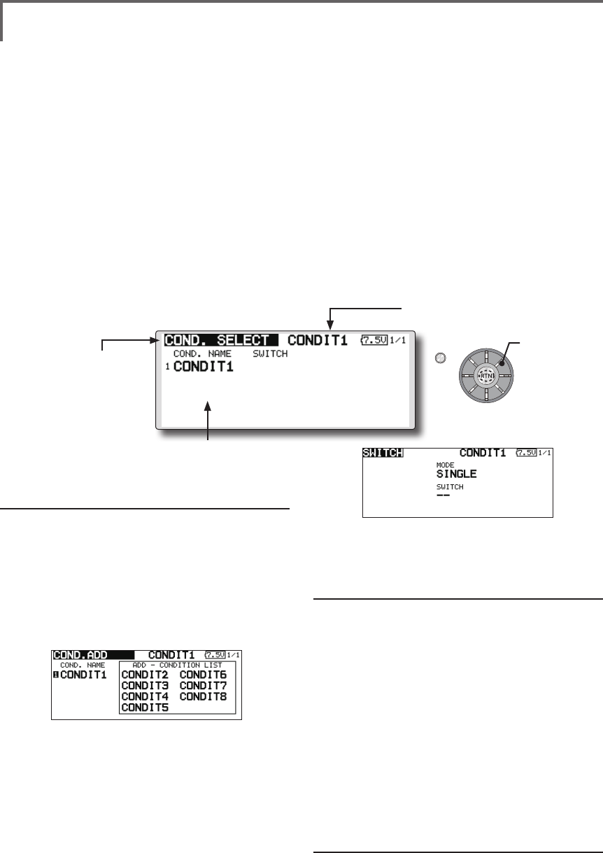
CONDIT. SELECT Flightcondition'saddition,deletion,copy,conditionrenaming,
andconditiondelaycanbeset.[Allmodeltypes]
The functions in the Model Menu can be used by
switching the settings of up to 8 flight conditions
by using the Condition Select function to add ight
conditions. Add conditions, as required.
When you do not want to use the Condition
Select function, this setting is unnecessary. In this
case, use the flight conditions assigned at initial
setting.
●Sinceswitchingbystickandleverposition,in
additiontoordinarytoggleswitch,ispossible
astheflightconditionselectorswitch,this
functioncanbelinkedwithotheroperations.
●AConditionDelayfunctioncanbeset.
Unnecessaryfuselagemotiongenerated
whentherearesuddenchangesintheservo
positionsandwhentherearevariationsin
theoperatingtimebetweenchannelsduring
conditionswitchingcanbesuppressed.The
delaycanbesetforeachchannel.
Whensettingthedelayfunctionatthe
switchingdestinationcondition,the
relatedfunctionchangesafteradelay
correspondingtothesetamount.
●Whenmultipleconditionswereset,their
operationprioritycanbefreelychanged.
●Theconditionnamecanbechanged.The
selectedconditionnameisdisplayed on
thescreen.Whenacondition hasbeen
added,giveitanamewhichcanbeeasily
conrmed.
(Conditions List)
(Currently selected condition name)
●Select[CONDIT.SELECT]atthemodelmenuandcallthe
setupscreenshownbelowbypushingtheRTNbutton.
(For a detailed description of the setting method, see [Switch
Setting Method] at the back of this manual.)
*The data (except the condition name) of the condition
currently being used is copied to the added condition.
Condition deletion
1.Usetheeditdialtomovethecursorto
theconditionyouwanttodeleteinthe
conditionslistandpushtheRTNbutton.
*The number before the condition name become reverse-
video to show that it is to be deleted.
2.Movethecursorto[REMOVE]andpushthe
RTNbutton.
*A conrmation message is displayed.
*Note that if initially operated up and down, the objective
condition changes.
3.WhentheRTNbuttonispushedagain,the
conditionisdeleted.(Operatetheeditdial
orS1buttontostopdeletion.)
PushtheRTNbuttontoendadjustmentand
returntothecursormovemode.
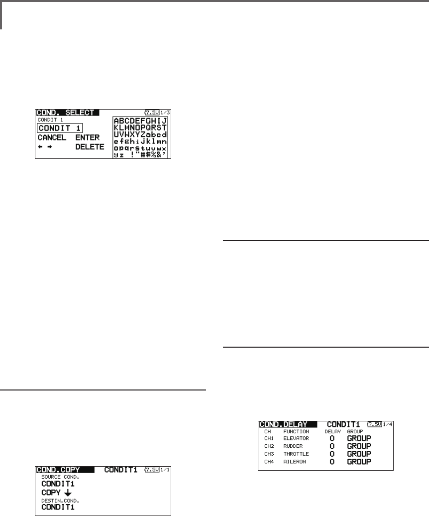
Condition name change
1.Usetheeditdialtomovethecursorto
theconditionyouwanttochangeinthe
*Perform the settings below after using the edit dial to move
the cursor to the item you want to set.
Condition addition
1.Usetheeditdialtomovethecursortoany
conditionintheconditionslistandpushthe
RTNbutton.
Movethecursortotheconditionyouwantto
add.
2.Movethecursorto[ADD]andpushtheRTN
button.
*Only the number of the conditions which can be added is
displayed.
3.AddtheconditionbypushingtheRTN
buttonagain.PushtheRTNbuttontoend
adjustmentandreturntothecursormove
mode.
4.Movethecursorto[SWITCH]item,call
theswitchsetupscreenbypushingthe
RTNbutton,andselecttheswitchandON
directiontobeusedinconditionswitching.
Scrolling
●Movingcursor
96 <Model Menu (Common Functions)>
conditionslist.
*The number before the condition name become reverse-
video to show that it is to be deleted.
2.Movethecursorto[RENAME]andpushthe
RTNbutton.
*The condition name setup screen appears.
3.Changetheconditionnameasdescribed
below:
[Movingcursorininputbox]
Select[←]or[→],andpushtheRTNbutton.
[Deletingacharacter]
When[DELETE]isselectedandtheRTN
buttonispushed,thecharacterimmediately
afterthecursorisdeleted.
[Addingacharacter]
Whenacandidatecharacterisselected
fromthecharacterlistandtheRTNbutton
ispushed,thatcharacterisaddedatthe
positionimmediatelyafterthecursor.
*A name of up to 8 characters long can be entered as the
condition name. (A space is also counted as 1 character.)
5.Attheendofinput,select[ENTER]andpush
theRTNbutton.(Toterminateinputand
returntotheoriginalstate,select[CANCEL]
andpushtheRTNbutton.)
Condition copy
1.Usetheeditdialtomovethecursortoany
conditionintheconditionslistandpushthe
RTNbutton.
2.Usetheeditdialtomoveto[COPY].
3.PushtheRTNbutton.
*The copy screen appears.
4.Usetheeditdialtomovethecursortothe
"SOURCECOND."(copysource)itemand
pushtheRTNbutton.
*The models already saved are displayed at the right side of
the screen.
5.Afterusingtheeditdialtomovethecursor
tothecopysourcecondition,pushtheRTN
button.
*The copy source condition is displayed at the "SOURCE
COND." position.
6.Usetheeditdialtomovethecursorto
"DESTIN.CND."(copydestination)andpush
theRTNbutton.
*The models already saved are displayed at the right side of
the screen.
7.Afterusingtheeditdialtomovethecursorto
thecopydestinationcondition,pushtheRTN
button.
*The copy destination conditions are displayed at the
"DESTIN.COND." position.
8.Usetheeditdialtomovethecursorto[COPY]
andpushtheRTNbutton.
9.WhentheRTNbuttonispushedagain,copy
isexecuted.(OperateeditdialorS1button
tostopcopying.)
PushtheRTNbuttontoendadjustmentand
returntothecursormovemode.
Priority change
1.Usetheeditdialtomovethecursortothe
conditionwhosepriorityyouwanttochange
intheconditionlist.
2.Movethecursorto[UP]or[DOWN]of
[PRIORITY]andpushtheRTNbutton.(Thelast
conditionbecomesthehighestpriority.)
*The initial setting condition cannot be shifted. The priority
is the lowest.
Condition delay setting
1.Usetheeditdialtomovethecursorto
theconditionyouwanttochangeinthe
conditionlistandpushtheRTNbutton.
2.Movethecursorto[DELAY]andpushtheRTN
button.
*The condition delay setup screen appears.
3.Usetheeditdialtomovethecursortothe
"DELAY"itemofthechannelyouwanttoset
andpushtheRTNbuttontoswitchtothe
datainputmode.
Adjustthedelayamountwiththeeditdial.
Initialvalue:0
Adjustmentrange:0~27(maximumdelay)
PushtheRTNbuttontoendadjustmentand
returntothecursormovemode.
● Thesettingmode(group[GROUP]/single
[SINGLE]mode)canbeswitched.
(For more information, see the description at the back of this
manual.)
97
<Model Menu (Common Functions)>
S1
●Selectthefunction
nameandreturntothe
precedingscreenby
pushingtheRTNbutton
orpushingtheHome/Exit
button.
<Editdial>
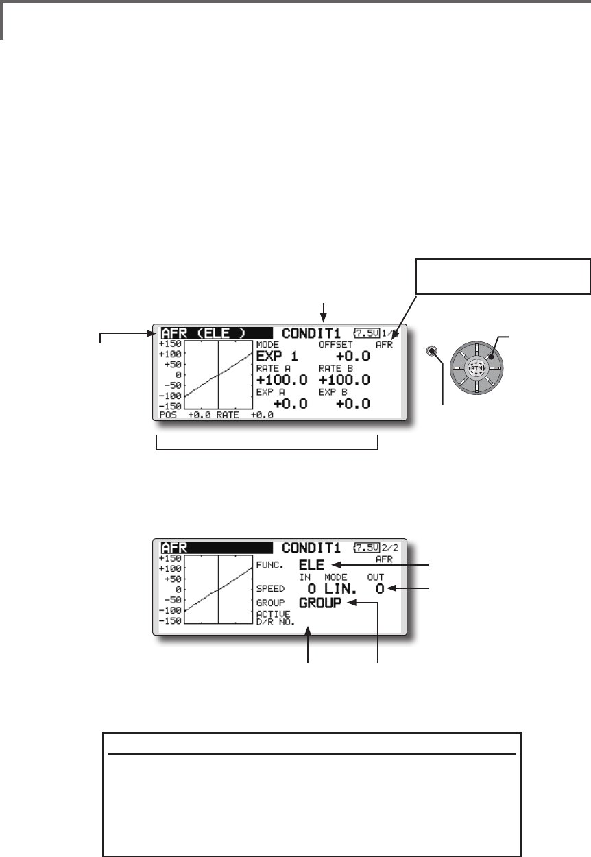
AFR Thefunctionrateandcurveofeachoperationfunctioncanbeset.[Allmodel
types]
AFR function is used to adjust the throw and
operation curve of the stick, lever, and switch
functions for each ight condition. This is normally
used after End Point has defined the maximum
throw. When mixing is applied from one channel
to another channel, both channels can be adjusted
at the same time by adjusting the operation rate
through the AFR function.
●Operationcurveadjustment:Threetypes
ofcurves(EXP1,EXP2,andPOINT)canbe
selected.Amaximum17pointscurvecanbe
usedforthepointcurvetype.(Initialsetting:
9points)Thenumberofpointscanalsobe
increasedanddecreasedandcurvesfrom
complexcurvestosimplecurvescanbe
used.
●Operationspeedadjustment:Theoperation
speedofeachfunctionwhenthefunction
isoperated(includingatflightcondition
switching)canbeadjusted.Thefunction
operatessmoothlyataconstantspeed
correspondingtothesetspeed.
(Currently selected condition name)
(Number of D/R curves set at the currently
selected condition)
●Servospeedsetting
(For a description of the setting
method, see the description at
the back of this manual.)
●
Group/singlemodeswitch(GROUP/SINGLE)
(For more information, see the description at the back
of this manual.)
●Operationcurvesetting
(For a description of the setting method, see the
description at the back of this manual.)
●Select[AFR]atthemodel menu and call the setup
screenshownbelowbypushingtheRTNbutton.
Function selection method
1.Usetheeditdialtomovethecursorto[FUNC.]andpushtheRTN
buttontoswitchtothedatainputmode.
2.Selectthedesiredfunction byscrollingtheeditdialtotheleftor
right,pushtheRTNbutton.
*The setting mode (group [GROUP]/single [SNGLE] mode) can be switched (For more
information, see the description at the back of this manual.)
[AFR, D/R]: Displays the currently
selected rate (AFR, D/R).
●Functionselection
Scrolling
●Movingcursor
●Selectingmode
●Adjustingvalue
●Pushthe S1 button
tocallnextpage.
98 <Model Menu (Common Functions)>
S1
●Selectthefunction
nameandreturntothe
precedingscreenby
pushingtheRTNbutton
orpushingtheHome/Exit
button.
<Editdial>
Dual rate adding
1.Movethecursortothe[INH]displayofan
unusedD/RandpushtheRTNbuttonto
switchtothedatainputmode.
Turnitoffbyscrollingtheeditdialtotheleft
andactivatetheD/Rfunctionbypushingthe
RTNbutton.
2.Movethecursortothe"FUNCTION"itemand
pushtheRTNbuttontoswitchtothedata
inputmode.
Selectthefunctionbyscrollingtheeditdial
andpushtheRTNbutton.
3.Movethecursortothe[SWITCH]itemand
calltheswitchsetupscreenbypushingthe
RTNbuttonandselecttheswitchandON
direction.Alternatemodecanbeassigned
todualrateswitch.
(For a detailed description of the setting method, see [Switch
Setting Method] at the end of this manual.)
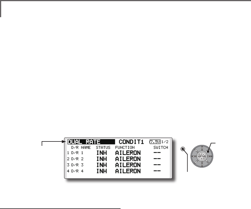
DUAL RATE [Allmodeltypes]
D/R curves which can be switched by switch,
etc. can be added. The curve can be adjusted by the
AFR function.
● Upto 6ratescan beaddedfor each
condition.
● D/Rissetforeachconditionandisnot
reectedatotherconditions.
● D/RatthetopoftheD/Rlisthaspriority.
●Select[DUALRATE]at the model menu and call the
setupscreenshownbelowbypushingtheRTNbutton.
Scrolling
●Movingcursor
●Selectingmode
●Adjustingvalue
●Pushthe S1 button
tocallnextpage.
99
<Model Menu (Common Functions)>
S1
●Selectthefunction
nameandreturntothe
precedingscreenby
touchingtheRTNbutton
orpushingtheHome/Exit
button.
<Editdial>
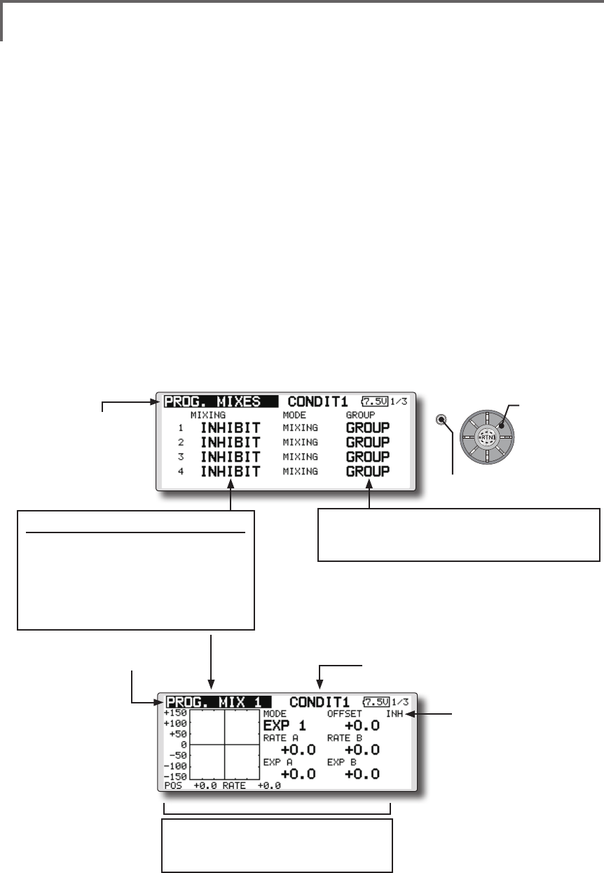
PROG. MIXES Programmixingwhichcanbefreelycustomized.Upto10
mixingscanbeusedforeachcondition.[Allmodeltypes]
Programmable mixing may be used to correct
undesired tendencies of the aircraft, and it may also
be used for unusual control congurations. Mixing
means that the motion of a command channel,
called the "master," is added to the motion of the
mixed channel, called "slave."
You may choose to have the Master's trim added
to the Slave channel response ("Trim" setting). The
mixing curve can be changed so that the undesired
tendencies can be corrected effectively by setting
the EXP1/EXP2/POINT modes. The Delay
function can be programmed for each rate. The
Delay is used to change the rate smoothly when
switching mixes. You may dene Mixing ON/OFF
switch, control or you may choose to have mixing
remaining on all the time. Mixing ON/OFF delay
time can be adjusted.
The Programmable mixing includes a powerful
link function, which allows Programmable mixing
to be linked with the special mixing functions, or
with other programmable mixing functions. The
link function can be set up for Master and Slave
channel individually.
The slave channel AFR mode (STK-STK mode)
may be selected, where the slave channel AFR and
D/R settings are observed when Link function is
set. The knob for ne tuning can be set up for every
mixing circuit. (Fine tune function)
The programmable mixing (in mixing mode)
STK to STK mixing function can be used even
when the Master is a stick or other hardware.
(Currently selected condition name)
●Select[PROG.MIXES]atthemodelmenuandcallthe
setupscreenshownbelowbypushingtheRTNbutton.
●Operationcurvesetting
(For a description of the setting method, see
the description at the back of this manual.)
●Mixoperatingdisplay
Mix setup screen call
● MovethecursortothemixNo.
whosefunctionyouwantto
activateandcallthesetupscreen
bypushingtheRTNbutton.
*When the function is activated, the master and
slave channel name or is displayed.
●Group/singlemodeswitching(GROUP/SINGLE)
(For more information, see the description at the back of
this manual.)
●Currentmixnumber
Scrolling
●Movingcursor
●Selectingmode
●Adjustingvalue
●Pushthe S1 button
tocallnextpage.
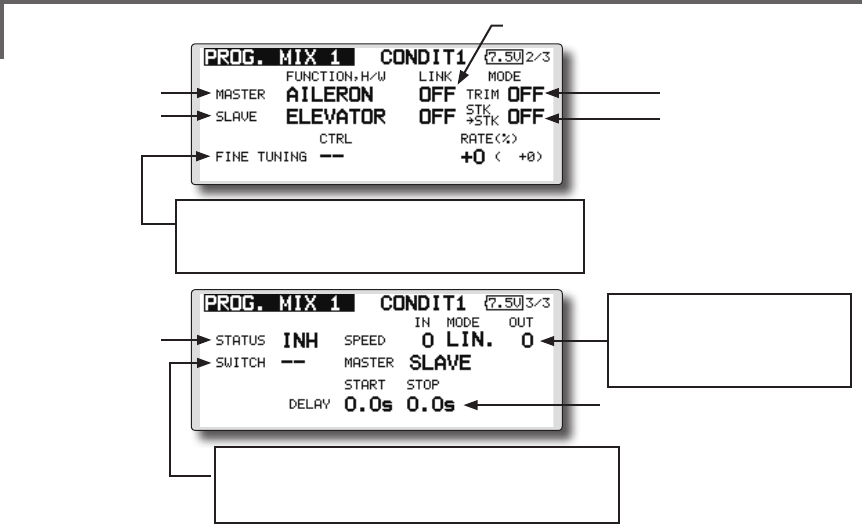
100 <Model Menu (Common Functions)>
*Perform the settings below after using the edit dial to move
the cursor to the item you want to set.
●Group/single mode selection
1.Whenyouwanttoactivatefunctionsforonly
selectedconditions,movethecursortothe
[GROUP]itemandpushtheRTNbuttonto
switchtothedatainputmode.
2.Turntheeditdialtotheleftuntil[SINGLE]
startstoblinkandthenpushtheRTNbutton.
*The mode changes to the single mode [SINGLE].
*When using common settings at each conditions, remain in
the [GROUP] mode.
●Activate the function.
1.Movethecursorto[INH]andpushtheRTN
buttontoswitchtothedatainputmode.
2.Turntheeditdialtotheleftuntil[ACT]starts
toblinkandthenpushtheRTNbutton.
*The function is activated. (ON or OFF display)
*ON/OFF switch and mix rate are not set even through the
function is activated.
●ON/OFF switch setting
Movethecursortothe[SWITCH]item,call
theswitchsetupscreenbypushingthe
RTNbutton,andselecttheswitchandON
direction.
(For a description of the setting method, see [Switch Setting
Method] at the back of this manual.)
*Always on when [--].
●Master channel setting
1.Movethecursortothe[FUNCTION.H/W]
itemof[MASTER]andpushtheRTNbuttonto
switchtothedatainputmode.
Selectthefunctionbyscrollingtheeditdial
andpushtheRTNbutton.
2.Whenyouwanttolinkthismixingwithother
mixes,movethecursortothe[LINK]itemand
pushtheRTNbuttontoswitchtothedata
inputmode.
Setthelinkmodeto[+]or[-]byscrollingthe
editdialandpushtheRTNbutton.
*Check the direction by actual operation.
*Master channel control can be set to simple operating
amount of sticks and VR which do not include ATV, AFR,
D/R, and mixing setting. In this case, the switch setup
screen is displayed by pushing the RTN button with "H/W"
selected by function selection. Select master channel side
control. (To terminate the "H/W" selection, select the [--]
display and push the RTN button.
●Slave channel setting
1.Movethecursortothe[FUNCTION.H/W]item
of[SLAVE]andpushtheRTNbuttontoswitch
tothedatainputmode.
Selectthefunctionbyscrollingtheeditdial
andpushtheRTNbutton.
2.Whenyouwanttolinkthismixwithother
mixes,movethecursortothe[LINK]itemand
pushtheRTNbuttontoswitchtothedata
inputmode.
Setthelinkmodeto[+]or[-]byscrollingthe
editdialandpushtheRTNbutton.
*Check the direction by actual operation.
●Servospeedsetting
(For a description of the setting
method, see the description at
the back of this manual.)
●Switchselection
(For a description of the switch setting method, see the
description at the back of this manual.)
●Finetuningtrimsetting
(For a description of the setting method, see the description
at the back of this manual.)
●Linksetting
●MasterCH
●SlaveCH
●Trimmodesetting
●SlaveCHAFRmode
●ON/OFF
●MixON/OFFdelay

101
<Model Menu (Common Functions)>
●Offset mode setting
Offset mode is function which allows
simultaneous offset control of up 4 slave functions
per circuit.
1.Use[MODE]settingtoselecttheprogram
mixingoparationmode.[MIXING]isthe
normalmixingmodeand[OFFSET]isthe
offsetmode.
2.Movethecursorto[INHIBIT]ofthemixing
No.settotheoffsetmodeandpushtheRTN
button.Thesetupscreenisdisplayed.
3.PresstheS1button.Page5/5isdisplayed.
4.Movethecursortothe[STATUS]itemand
switchtothedatainputmodebypushing
theRTNbutton.
5.Turnthedialtotheleftandrightuntil[ACT]
blinks,andthenpushtheRTNbutton.To
deactivatethefunction,switchto[INH].
●ON/OFF switch selection
Movethecursortothepage5/5[SWITCH]
item,calltheswitchsetupscreenby
pushingtheRTNbutton,andthenselectthe
switchandONdirection.(Foradetailed
descriptionoftheselectionmethod,see
[SwitchSelectionMethod]atthebackofthe
instructionmanual.)
●Slave No. selection
SettingoftheslaveNo.from1to4atpages
1/5~4/5isdisplayed.WhentheS1buttonis
pushed,thedisplayedslaveNo.isswitched.
●Slave function setting
Movethecursortothe[FUNCTION]item
andswitchtothedatainputmodeby
pushingtheRTNbutton.Selectthefunction
byscrollingthedialandthenpushtheRTN
button.
●Offset rate setting
The function operation offset amount when
the mixing switch is ON and OFF can be set
independently.
1.Movethecursortothe[ON]or[OFF]item
andswitchtothedatainputmodeby
pushingtheRTNbutton.
2.Turnthedialtotheleftandrightandsetthe
offsetratewhentheswitchisONorOFF.
Initialsetting:0%
Settingrange:-300%~+300%
3.Aftersetting,switchtothecursormovemode
bypushingtheRTNbutton.
*At adjustment, the offset rate is reset to the initial value by
pushing the RTN button for 1 second.
●Trim mode ON/OFF setting
1.Whenchangingthetrimmode,movethe
cursortothe[TRIM]itemandpushtheRTN
buttontoswitchtothedatainputmode.
SelectON/OFFbyscrollingtheeditdialand
settheselectionbypushingtheRTNbutton.
*When mixing includes master side trim, select [ON] and
when mixing does not include master trim, select [OFF].
*Effective when a function is set at the master channel.
●Slave channel AFR mode setting (STK-STK)
1.Movethecursortothe[STK-STK]item,
selectthemodebyscrollingtheeditdial,
andchangethemodebypushingtheRTN
button.
*When link is set at the slave side, and you want to add AFR
(D/R) to the mixing rate, select [ON].
*This is effective when the linkage is the same, but the travels
are substantially different.
●Mixing curve setting
(For a description of the curve setting method, see the
description at the back of this manual.)
●Fine tuning trim setting
Operation control [CTRL], operation mode
[MODE], and rate [RATE] adjustment is possible
by [FINE TUNING] item.
(For a description of the ne tuning trim setting method, see
the description at the back of this manual.)
●Servo speed setting
Adjustment is possible with the [SPEED] item.
(For a description of the servo speed setting method, see the
description at the back of this manual).
●Mixing ON/OFF delay setting
Delay time at mix ON [START] and delay time
at mix OFF [STOP] adjustment is possible by
[DELAY] item.
*This function is inactive when a mixing switch is not set.
1.Movethe[START]or[STOP]itemandpush
theRTNbuttontoswitchtothedatainput
mode.
2.Adjustthedelaytimebyscrollingtheedit
dial.
Initialvalue:0.0sec
Adjustmentrange:0~4sec
(When the RTN button is pushed for 1 second, the delay time
is reset to the initial value.)
PushtheRTNbuttontoendadjustmentand
returntothecursormovemode.

102 <Model Menu (Common Functions)>
●Fine tuning trim setting
Operation control [CTRL], operation mode
[MODE], and rate [RATE] adjustment is possible
by [FINE TUNING] item.
(For a description of the ne tuning trim setting method, refer
to [Fine tuning trim setting] at the back of this manual.)
●Operation mode setting
The operation mode when the switch was
operated is selected. Normal mode [NORM] or
timer mode [TIME] can be selected.
[Normal mode]
After the switch is set to ON, mixing is turned
ON after the time set by start delay ([START]) has
elapsed. Similarly, after the switch was set to OFF,
mixing is turned OFF after the time set by stop
delay ([STOP]) has elapsed.
[Timer mode]
After the switch was set to ON, mixing is turned
ON after the time set by start delay ([START]) has
elapsed. Mixing is automatically turned OFF after
the time set by stop delay ([STOP]) has elapsed.
Examples of use are jet plane and scale model
retractable landing gear and cover linked mixing,
etc.
●Servo speed setting
The speed at function operation can be adjusted.
(For a description of the setting method, refer to
[Servo speed setting] at the back of the instruction
manual.)
●Delay setting
Mixing operation at mixing switch ON
([START]) and OFF ([STOP]) can be delayed by
[DELAY] item.(When switch is set.)
1.Movethecursortothe[START]or[STOP]
itemandswitchtothedatainputmodeby
pushingtheRTNbutton.
2.Turnthedialtotheleftandrightandsetthe
mixingoperationdelaytimeatswitchONor
OFF.
Initialsetting:0sec
Settingrange:0sec~35sec
3.Afteradjustment,switchtothecursormove
modebypushingtheRTNbutton.
*At adjustment, the delay time can be reset to the initial value
by pushing the RTN button for 1 second.
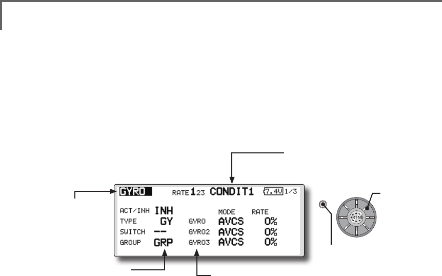
103
<Model Menu (Common Functions)>
S1
●Selectthefunction
nameandreturntothe
precedingscreenby
pushingtheRTNbutton
orpushingtheHome/Exit
button.
<Editdial>
GYRO [Correspondingmodeltype]:Multicopter/Airplane/glider,general
This function is used when a GYA Series gyro
is used to stabilize the aircraft's attitude. The
sensitivity and operation mode (Normal mode/GY
mode) can be switched with a switch.
●Threerates(Rate1/Rate2/Rate3)canbe
switched.
●Upto3axes(Gyro/Gyro2/Gyro3)canbe
simultaneouslycontrolled.
*Initial setting does not assign a sensitivity channel. Use the
Function menu of the Linkage Menu to assign the sensitivity
channel (Gyro/Gyro2/Gyro3) used to a vacant channel
beforehand.
Set [Control] and [Trim] other than Function to [--].
●Theoperationmode(AVCS/NOR)andsensitivityofthe
3axiscontrolledbyGyro/Gyro2/Gyro3canbeset.
●Group/singlemodeswitching
(For more information, see the
description at the back of this
manual.)
●Threerates(Rate1/Rate2/Rate3)canbeused.
Movethecursortothe[RATE]itemandpushtheRTNbuttontoswitchto
thedatainputmode.Adjusttheratebyscrollingtheeditdial.
●Whenusingthisfunction, movethecursortothe[ACT]itemandpush
theRTNbuttontoswitchtothedatainputmode.Turntheeditdialto
theleftandpushtheRTNbutton.
●WhenaFutabaGYAgyroisused,when[GY]typeisselected,the
sensitivitysetvalueisdirectlyreadinboththeAVCSandNORMmodes.
●Whensettingaswitch,movethecursortotheSWITCHitemandpress
theRTNbuttontocalltheselectionscreen,andthenselecttheswitch
andsetitsONdirection.
(Foradescriptionoftheswitchselectionmethod,seethedescriptionat
theendofthismanual.)
(Currently selected condition name)
●Select[GYRO] at themodelmenuand
callthesetupscreenshownbelowby
pushingtheRTNbutton.
Scrolling
●Movingcursor
●Selectingmode
●Adjustingvalue
●Pushthe S1 button
tocallnextpage.
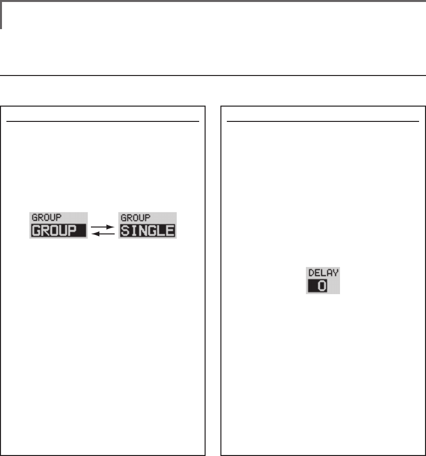
104 <Data>
This section describes the functions often used at the function setup screen. Refer to it when setting each
function.
Operations related to ight conditions
COMMON OPERATIONS USED IN FUNCTION SETUP SCREEN
Group/single mode switching (GROUP/SINGLE)
When setting multiple flight conditions,
linking the setting contents with all conditions
(group mode) or setting independently (single
mode) can be selected. The mode can be
changed at the [GROUP] item on each setup
screen.
[Group/single mode switching]
1. Use the edit dial to move the cursor
(reverse-will display) to the [GROUP] item
on the setup screen and push the RTN
button to switch to the data input mode.
2. Turn the edit dial to the left until switch
[SINGLE] starts to blink.
*At this point, the mode has still not been changed.
*When changing from [SINGLE] to [GROUP], turn the
edit dial to the right.
3. Change the mode by pushing the RTN
button.
●Group mode (GROUP)
The same setting contents are set to all
the ight conditions.
●Single mode (SINGLE)
Set this mode when the setting contents
are not linked with other conditions.
Condition delay setting
Unnecessary fuselage motion generated when
there are sudden changes in the servo position
and variations in the operating time between
channels can be suppressed by using the
condition delay function of the condition select
function [COND. SELECT].
When the delay function is set at the
switching destination condition, a delay
corresponding to that amount is applied and the
related functions change smoothly.
[Setting method]
*At the condition delay setup screen [COND.DELAY],
move the cursor to the [DELAY] item of the channel you
want to set and perform the following settings:
1. Switch to the condition you want to set
and push the RTN button to switch to the
data input mode.
2. Set the delay by turning the edit dial.
Initial value: 0
Adjustment range: 0~27 (maximum delay)
(When the RTN button is pushed for 1 second, the delay is
reset to the initial value.)
3. Push the RTN button to end adjustment
and return to the cursor move mode.
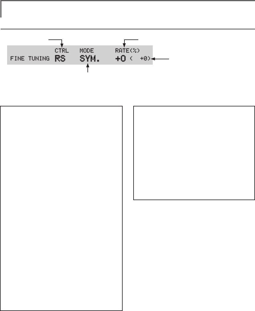
105
<Data>
Operations related to ne tuning VR
●VR selection ●Rate adjustment
(Fine tuning VR operation position)
●Operation mode selection
*The operation modes which can be
selected depend on the function.
[Fine tuning VR operation mode]
[LIN.] Mixing rate 0% at center of VR.
When the VR is turned clockwise and
counterclockwise, the mixing rate
increases and decreases, respectively.
[ATL+] Mixing rate 0% at left end of VR.
When the VR is turned, the mixing rate
increases.
[ATL-] Mixing rate 0% at right end of VR.
When the VR is turned, the mixing rate
increases.
[SYM.] When the VR is turned to the left or
right of the neutral position, the mixing
rate increases.
[Setting method]
1. Control selection
Use the edit dial to move the cursor
(reverse-will display) to the [CTRL] item and
push the RTN button to call the selection
screen.
Move to the control you want to set by
turning the edit dial to the left or right and
push the RTN button.
2. Mode selection
Use the edit dial to move the cursor to the
[MODE] item and push the RTN button to
switch to the data input mode.
Turn the edit dial to the left or right and
switch to the operation mode ([LIN.], [ATL+],
[ATL-], or [SYM.]) corresponding to the set
control and push the RTN button.
3. Rate adjustment
Move the cursor to the [RATE] item and
push the RTN button to switch to the data
input mode.
Turn the edit dial to the left or right and set
the rate.
Initial value: 0%
Adjustment range: -100%~+100%
(When the RTN button is pushed for 1 second, the rate is
reset to the initial value.)
Push the RTN button to end adjustment and
return to the cursor move mode.
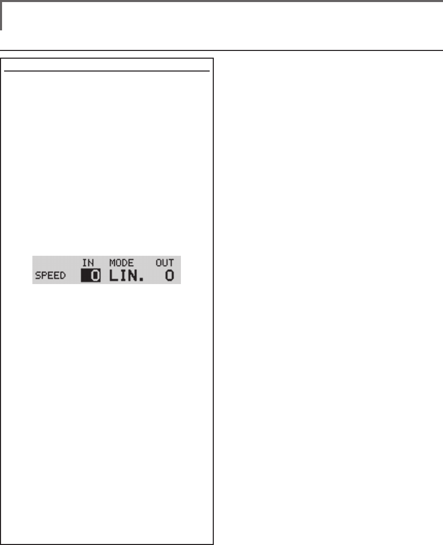
106 <Data>
Operations related to servo speed
Servo speed setting
The servo speed at each function operation
(including flight condition switching) can be
adjusted. The servos operate smoothly at a
fixed speed corresponding to the set speed. The
operating speed (IN side) and return speed (OUT
side) can be set individually.
Switch the operation mode according to the set
function.
"SYM." mode: Used with ailerons and other
self neutral functions.
"LIN." mode: Used with functions which hold
the operation position of the throttle and
switch channel, etc.
[Setting method]
1. Use the edit dial to move the cursor
(reverse-will display) to the [MODE] item
and push the RTN button to switch to the
data input mode.
Turn the edit dial to the left or right and
switch to the operation mode ("SYM." or
"LIN.") corresponding to the set function
and push the RTN button.
2. Move the cursor to the direction ([IN] or
[OUT]) item you want to set and push the
RTN button to switch to the data input
mode.
Turn the edit dial to the left or right and set
the speed.
Initial value: 0
Adjustment range: 0~27 (maximum delay)
(When the RTN button is pushed for 1 second, the servo
speed is reset to the initial value.)
Push the RTN button to end adjustment and
return to the edit mode.
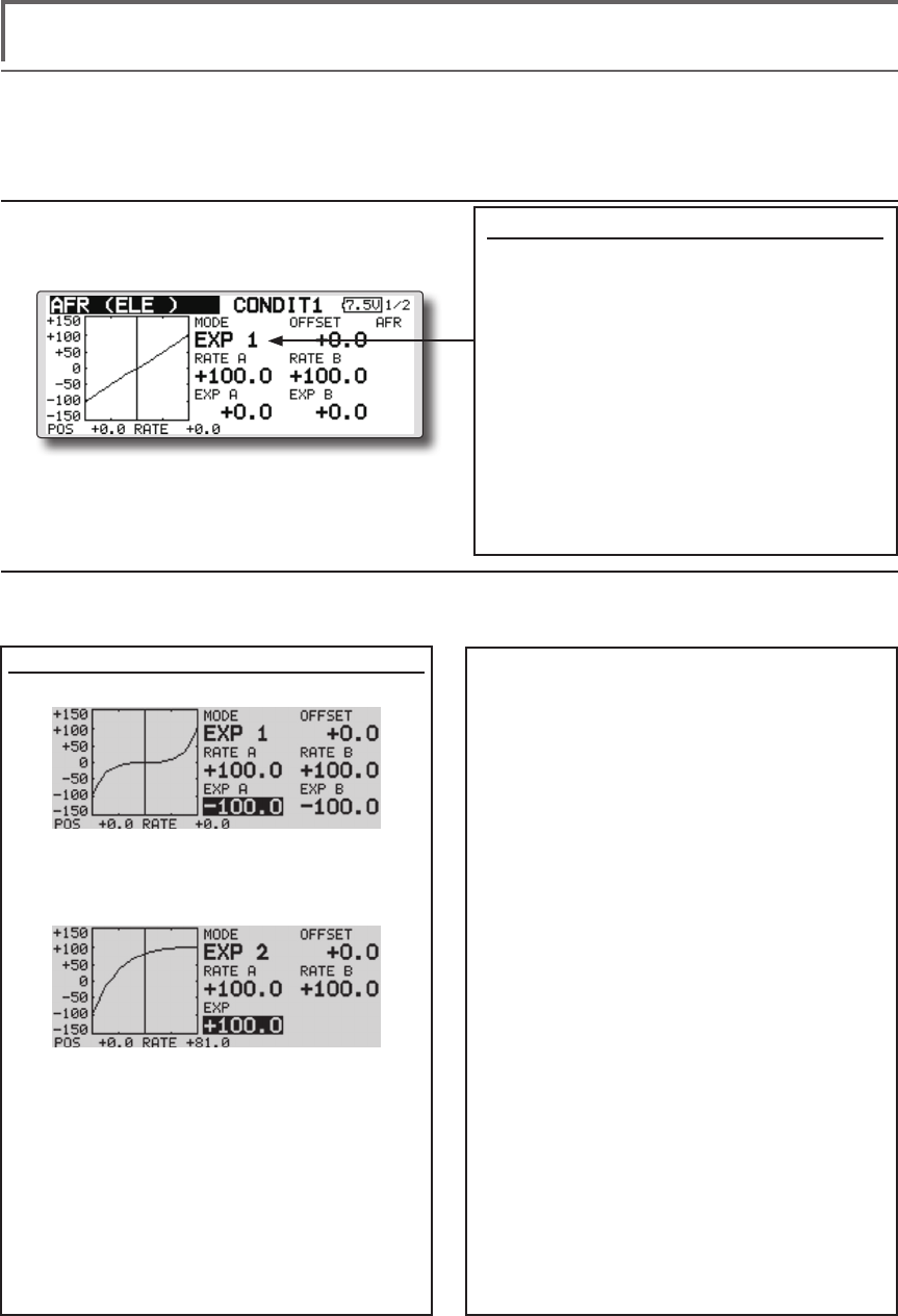
107
<Data>
Curve setting operation
This section describes the setting procedure of curves which are used with the AFR function and each
mixing function.
Curve type selection
Three types of curves (EXP1, EXP2 and
POINT) can be selected.
Curve type selection
1. Use the edit dial to move the cursor
(reverse-will display) to the [MODE] item
and push the RTN button to switch to the
data input mode.
2. Display the curve you want to use by
turning the edit dial to the left or right.
*The curve type blinks.
3. When the RTN button is pushed, the curve
type is changed. (Operate the edit dial
or S1 button to stop the change.)
[EXP1]: EXP1 curve
[EXP2]: EXP2 curve
[POINT]: point curve
Setting by curve type
When the curve type is selected as described above, adjustment items corresponding to the curve type
appear on the screen. Adjust each curve as described below.
B], [EXP A], or [EXP B] setting item and
push the RTN button to switch to the data
input mode.
2. Set the rate by turning the edit dial to the
left or right.
Initial value: +100.0% (rate)/+0.0% (EXP
rate)
*Initial value differs depending on function.
Adjustment range: -200.0~+200.0% (rate)/-
100.0~+100.0% (EXP rate)
(When the RTN button is pushed for 1 second, the rate is
reset to the initial value.)
Push the RTN button to end adjustment and
return to the cursor move mode.
[Offsetting the curve horizontally in the
vertical direction]
1. Use the edit dial to move the cursor
(reverse-will display) to the [OFFSET] setting
item and push the RTN button to switch to
the data input mode.
2. Move the curve in the vertical direction by
turning the edit dial to the left or right.
Initial value: +0.0%
(When the RTN button is pushed for 1 second, the rate is
reset to the initial value.)
Push the RTN button to end adjustment and
return to the cursor move mode.
EXP1/EXP2 curve adjustment
(EXP1 curve)
Using the EXP1 curve is effective in smoothing
starting of the ailerons, elevator, rudder, etc.
(EXP2 curve)
Using the EXP2 curve is effective in engine
rise and other engine control.
The curve left and right rates ([RATE A],
[RATE B]) and EXP curve rate ([EXP A], [EXP
B]) can be adjusted individually. ([EXP] for
EXP2)
The curve can also be offset horizontally
([OFFSET]) in the vertical direction.
[Rate setting]
1. Use the edit dial to move the cursor
(reverse-will display) to the [RATE A], [RATE
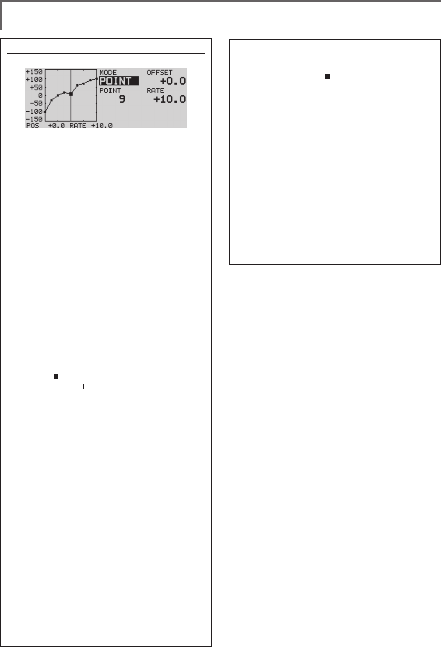
108 <Data>
Point curve (POINT) adjustment
(Point)
Up to 11 or 17 points curve can be used.
(differs with function)
Initial point number: 9 points (17 points
curve), 11 points (11 points curve)
*The set points can be freely increased, decreased, and
offset.
[Rate adjustment of each point]
1. Use the edit dial to move the cursor
(reverse-display) to the [POINT] or [RATE]
item and push the RTN button to switch to
the curve setting mode.
*It is changed from the reverse-display to the square box
display.
*In this mode, push the RTN button to switch the [POINT]
item and [RATE] item alternately.
2. Move the cursor (square box) to the
[POINT] item by pushing the RTN button.
3. Turn the edit dial to the left or right and
select the point whose rate you want to
set.
*The mark on the curve shows the currently selected
point. The mark on the curve shows the currently
deleted point.
4. Move the cursor (square box) to the [RATE]
item by pushing the RTN button and set
the rate by turning the edit dial to the left
or right.
Repeat steps 2 through 5 and adjust the
curve.
Push the S1 button to end adjustment and
return to the cursor move mode.
[Point addition]
1. In the curve setting mode, push the RTN
button to move the cursor to the [POINT]
item and turn the edit dial to the left or
right and move the cursor on the curve to
the position (mark ) you want to add.
2. When the RTN button is pushed for 1
second, the point is added.
[Point deletion]
1. In the curve setting mode, push the RTN
button to move the cursor to the [POINT]
item and turn the edit dial to the left or
right and move the cursor on the curve to
the position (mark ) you want to delete.
2. When the RTN button is pushed for 1
second, the point is deleted.
[Offsetting the curve horizontally in the
vertical direction]
1. Use the edit dial to move the cursor
(reverse-will display) to the [OFFSET] item.
2.
Move the curve in the vertical direction by
turning the edit dial to the left or right.
Initial value: +0.0%
(When the RTN button is pushed for 1 second, the curve is
reset to the initial value.)
Push the RTN button to end adjustment and
return to the cursor move mode.
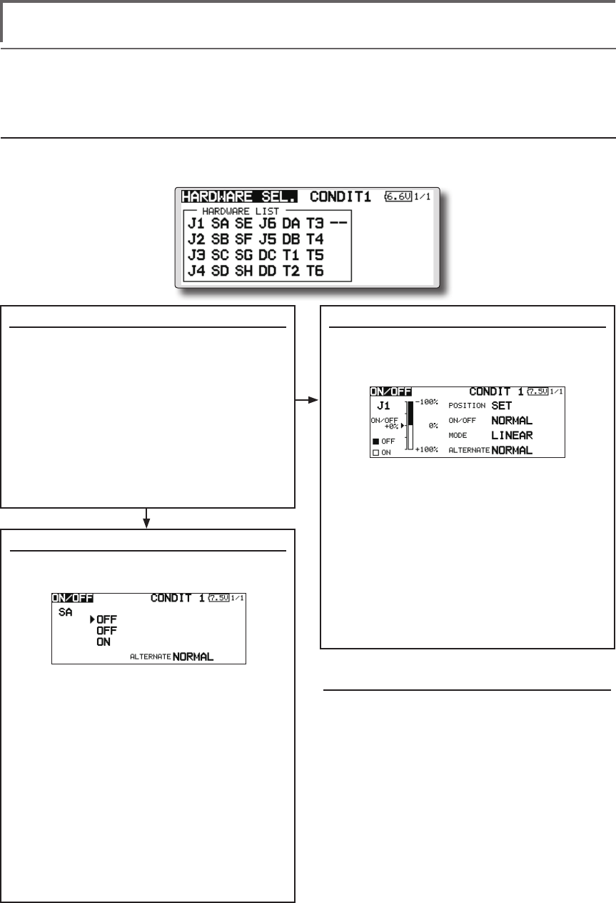
109
<Data>
Switch selection method
The various functions used in the FMT-03 can be selected by switch. The switch (including when stick,
trim lever, or VR are used as a switch) setting method is common to all functions.
Switch selection
When a switch is selected at a mixing function, etc., the selection screen shown below is called.
(Switch selection screen example)
When switch was selected
When switch was selected, ON/OFF position
setting is also performed.
*The ON/OFF setting state of each position is displayed.
1. When you want to change the ON/OFF
setting, use the edit dial to move the
cursor and push the RTN button to switch
to the data input mode. Switch the ON/
Off display by turning the edit dial to the
left or right.
*ON/OFF display blinks.
2. When the EDIT button is pressed, the ON/
OFF setting is changed. (Operate the edit
dial or S1 button to stop the change.)
3. To return to the preceeding screen, move
the cursor to the [ON/OFF] at the top of
the screen and push the RTN button.
When stick, trim lever, or knob selected
When a stick, trim lever, or knob is used as a
switch, four operation modes can be selected by
the following mode and type combination:
1. When you want to change the mode,
move the cursor to [MODE] and push the
RTN button to switch to the data input
mode. Switch the display to the mode
you want to change by turning the edit
dial to the left or right and then make the
change by pushing the RTN button.
●
Mode: [LINEAR]/[SYMMETRY]
*
Set the ON/Off point by the method described on the next page.
Switch selection
1. Use the edit dial to move the cursor
(highlights) to the switch you want to
select and push the RTN button.
*The switch blinks.
2. To return to the preceeding screen, move
the cursor to the [HARDWARE SEL.] at
the top of the screen and push the RTN
button.
Or, move the cursor to the [ON/OFF] and
call the ON/OFF position setting screen by
pushing the RTN button.
Alternate mode setting
●
Mode: [NORMAL]/[ALTERNATE]
1. Move the cursor to the [ALTERNATE] item
and push the RTN button to switch to the
data input mode.
2. Change to the mode you want to set by
turning the edit dial to the left or right.
*The mode display blinks.
3. Push the RTN button. (Operate the edit dial
or S1 button to stop the change.)
4. To return to the preceeding screen, move
the cursor to the [ON/OFF] at the top of the
screen and push the RTN button.
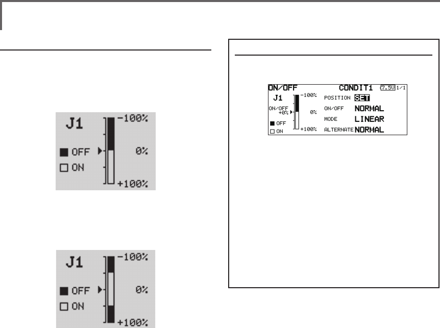
110 <Data>
Operation modes
The operation modes when stick, trim lever, or
knob are selected is described below.
Linear mode
This mode sets ON/OFF at the left or right (up or
down) with the set point as the reference.
Symmetrical mode
Left and right (up and down) operations are
symmetrical about the neutral position. For
instance, when you want to switch DR1 with the
aileron stick, when the stick is moved to the left or
right, DR1 can be turned on at the same left and
right position.
Shifting the ON/Off point
The ON/OFF point can be shifted. ON/OFF
at a free position can be changed.
●Black range: OFF range
●White range: ON range
[Setting method]
1. First, use the edit dial to move the cursor
to the [POSITION] item.
2. Move the stick, trim lever, or knob to the
point you want to change and push the
RTN button. The point is shifted.
3. To return to the preceeding screen, move
the cursor to the [ON/OFF] at the top of
the screen and push the RTN button.
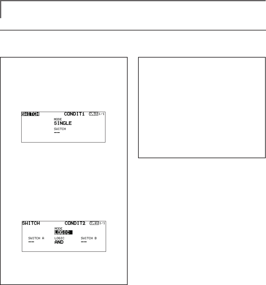
111
<Data>
Logic mode
AND: When both switches are ON, the
condition is ON.
OR: When either switches is ON, the
condition is ON.
EOR: When the two switches are in different
states, the condition is ON.
Switch mode selection
1. Move the cursor to the [MODE] item and
push the RTN button to switch to the data
input mode.
2. Turn the edit dial to the left and select the
[LOGIC].
*[LOGIC] display blinks.
3. Push the RTN button to change to the logic
switch mode.
(Logic switch setting screen)
Swich selection
1. Select the switch A and B. (Refer to the
description at the previous page.)
Logic mode selection
1. Move the cursor to the [LOGIC] item and
push the RTN button to switch to the data
input mode.
2. Turn the edit dial to the left or right and
select the logic mode.
*The mode display blinks.
3. Push the RTN button to change to the logic
mode.
4. To return to the preceeding screen, move
the cursor to the [SWITCH] at the top of the
screen and push the RTN button.
Logic switch (Condition Select function only)
The logic switch function lets you turn operation on and off by combining two switches. For instance,
the condition is activated when 2 switches are turned on.
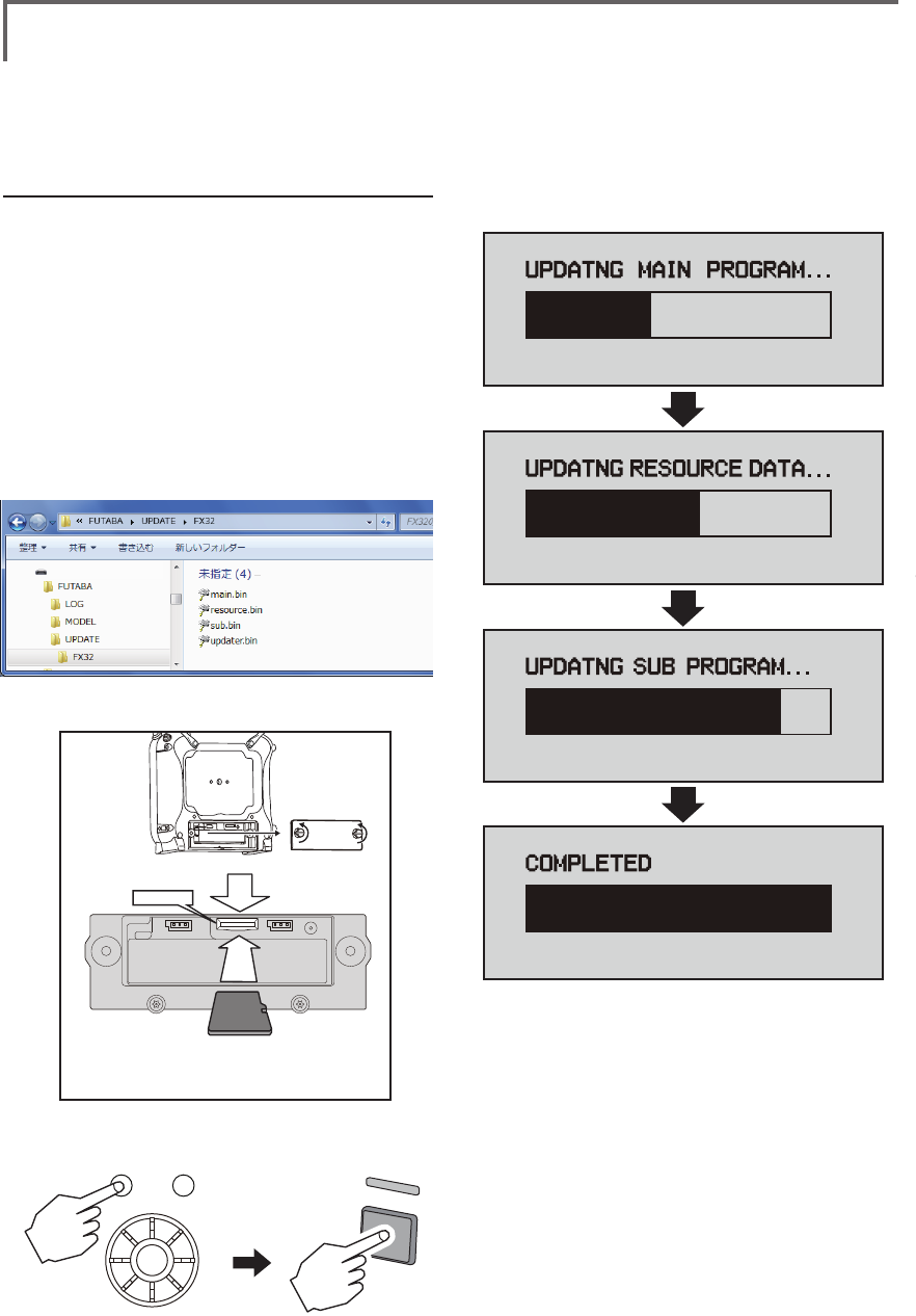
112 <Data>
UPDATING
Your Futaba FMT-03 transmitter programming can be updated easily online. When functions are added
or improved, the update le can be downloaded from our website. Copy the update les to the SD card
and then use the following procedure to update the program.
Check our web site for the FAQ regarding updating for more information.
Updating procedure
Note: If the battery fully discharges during
program updating, updating will fail. When
the remaining battery capacity is 50% or
less, always recharge the battery before
updating.
Note: The model data in the transmitter can
be used unchanged after updating, but to
be safe, back up the model data before
updating.
1. Copy update files to a SD card. Typical
structure of folders of the card for update
are following.
2. Attach the SD card into the SD slot of the
FMT-03.
3. Press the Home/Exit switch and turn on the
power switch, and FMT-03 should begin to
update.
4. When updating is complete, the screen
shown below appears.
5. Turn off the power switch. After the monitor
LED goes off, switch the update switch in the
down direction.
After the updating above has been
completed, turn on the power and then
check the system program version at the
system menu information screen.
6. If writing goes wrong, the following error
message will come out.
"LOW BATTERY"
"UPDATE FILE NOT FOUND"
"BROKEN FILE"
"WRITE ERROR"
Removable disk (E:)
② It inserts until it locks micro SD card into SD card slot.
*It is releasable if a card is pushed once again.
*Don't mistake the
direction that the
micro SD card is
inserted.
① Open the battery cover. (Minus driver is used.)
SD card slot

113
<Model Menu (Airplane/Glider Functions) >
Reference FMT-03 is equipped with a stick of multi-copter exclusive use. Therefore it's
unsuitable for use of an airplane, a glider and a helicopter.
AIRPLANE/GLIDER/HELICOPTER FUNCTIONS
FMT-03 is equipped with a stick of
multi-copter exclusive use. Therefore
it's unsuitable for use of airplane,
glider and helicopter.
But, FMT-03 is also equipped with the
function of the airplane, glider and
helicopter. It's indicated on a page
after this by reference.
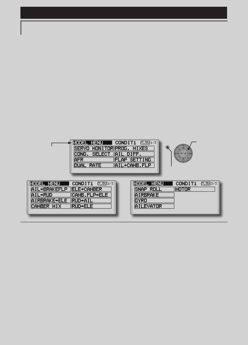
114 <Model Menu (Airplane/Glider Functions) >
Reference FMT-03 is equipped with a stick of multi-copter exclusive use. Therefore it's
unsuitable for use of an airplane, a glider and a helicopter.
●Selectthe[MODELMENU]
andreturnto the home
screenbypushingthe
RTNbuttonorpushingthe
Home/Exitbutton.
MODEL MENU (AIRPLANE/GLIDER FUNCTIONS)
The dedicated mixes, etc. usable when airplane
or glider model type is selected are displayed in
this Model Menu functions section. First use the
Model Type function of the Linkage Menu to
preset the model type, wing type, and tail type
matched to the fuselage used. Other settings reset
the data used in mixing function, etc.
These dedicated mixes can be set for each
flight condition, as required. When you want to
use the system by switching the settings for each
condition by switch or stick position, use the
Condition Select function to add ight conditions.
(Up to 8 conditions can be used)
Note:TheFMT-03isdesignedsothattheairplane
andglidermodeltypescanhandleaircraftofthe
samewingtype.
Thefunctionscommontoairplanesandgliders,
exceptsomededicatedfunctions,aresummarized
withoutregardtothemodeltype.
Thesettingitemsaredifferent,dependingonthe
numberofservos,etc.accordingtothewingtype
used.Thesetupscreensintheinstructionmanual
aretypicalexamples.
Model Menu functions list
AIL DIFFERENTIAL
This function adjusts the left and right ailerons.
Roll axis correction and ne tuning with a VR are
also possible. This is convenient when making
settings during ight.
[Airplane/glider, 2 ailerons or more]
FLAP SETTING
The aps can be adjusted independently. For a
4 aps model, the camber aps can be mixed with
the brake aps. [Airplane/glider, 2 aps or more]
AIL to CAMBERFLP
This mix operates the camber flaps in
the aileron mode. It improves the operation
characteristic of the roll axis. [Airplane/glider, 2
ailerons + 2 aps or more]
AIL to BRAKEFLP
This mix operates the brake aps in the aileron
mode. It improves the operation characteristic of
the roll axis. [Airplane/glider, 4 aps or more]
AIL to RUD
This mix is used when you want to operate the
rudder at aileron operation. Banking at a shallow
bank angle is possible. [Airplane/glider, general]
AIRBRAKE to ELE
This mix is used to correct operation of the
airbrakes (spoilers) when landing. [Airplane/
glider, general]
(Model Menu screen example)
*The Model Menu screen depends on the model type.
This screen is for model type 4AIL+4FLP.
●Selectthe [MODEL] atthehomescreenandcallthe
modelmenushownbelowbypushingtheRTNbutton.
●Usetheeditdialtoselectthefunctionyouwanttoset
andcallthesetupscreenbypushingtheRTNbutton.
S1
<Editdial>
●Pushthe S1 button
tocallnextpage.
Scrolling
●Movingcursor
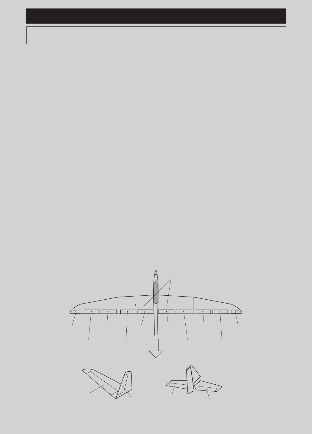
115
<Model Menu (Airplane/Glider Functions) >
Reference FMT-03 is equipped with a stick of multi-copter exclusive use. Therefore it's
unsuitable for use of an airplane, a glider and a helicopter.
AIL 3
(Chip Aileron) AIL 4
(Chip Aileron)
AIL1
(Main Aileron) AIL 2
(Main Aileron)
FLP 2
(Camber Flap)
FLP 1
(Camber Flap)
ELEVATOR
(ELEVATOR 2)
V-TAIL AILVATOR
FLP 3
AIR BRAKE
(Brake Flap)
FLP 4
(Brake Flap) RUDDER 2
Winglet
RUDDER 1
RUDDER
(RUDDER 2)
Winglet
at Flying wing at Flying wing
( ) ( )
ELEVATOR ELEVATOR 2
(AILERON 5)
(AILERON 6)
RUD to AIL
This mix is used to correct roll maneuvers,
knife edge, etc. of stunt planes. [Airplane/glider,
general]
CAMBER Mix
This mix adjusts the camber and corrects the
elevators. [Airplane/glider, 2 ailerons or more]
ELE to CAMBER
This mix is used when you want to the mix
camber aps with elevator operation. Lifting force
can be increased at elevators up. [Airplane/glider,
2 ailerons or more]
CAMBERFLP to ELE
This mix is used to correct for attitude changes
when the camber aps are being used. [Airplane/
glider, 2 ailerons + 1 ap or more]
BUTTERFLY (Crow)
This function is used when powerful brake
operation is necessary. [Glider, 2 ailerons or
more]
TRIM MIX 1/2
The ailerons, elevators, and flaps trim offset
rate can be called by switch or condition selection.
[Glider, 2 ailerons or more]
AIRBRAKE
This function is used when airbrakes are
necessary when landing or when diving, etc.
during ight. (Airplane, general)
GYRO
This is a dedicated mix when a GYA Series
gyro is used. [Airplane/glider, general]
V-TAIL
This function adjusts the elevators and
rudder of V-tail models. [Airplane/glider, V-tail
specications]
AILEVATOR
This function adjusts the elevators and ailerons
of models with elevator specications. [Airplane/
glider, elevator specications]
WINGLET
This function adjusts the left and right rudders
of winglet models. [Airplane/glider, winglet
specications]
MOTOR
The operation speed when the motor of F5B
and other EP gliders is started by switch can be
set. [EP glider, general]
RUD to ELE
This function is used to correct roll maneuvers,
knife edge, etc. of stunt planes. [Airplane,
general]
SNAP ROLL
This function selects the snap roll switch and
adjusts the steering angle of each rudder. Servo
speed can also be adjusted. [Airplane general]
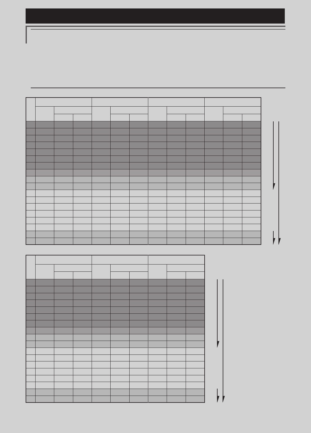
116 <Model Menu (Airplane/Glider Functions) >
Reference FMT-03 is equipped with a stick of multi-copter exclusive use. Therefore it's
unsuitable for use of an airplane, a glider and a helicopter.
Servo connection by Airplane/glider type
The FMT-03 transmitter channels are automatically assigned for optimal combination according to the
type selected with the Model Type function of the Linkage Menu. The channel assignment (initial setting)
for airplane/glider type is shown below. Connect the receiver and servos to match the type used.
*The set channels can be checked at the Function screen of the Linkage Menu. The channel assignments can also be changed.
For more information, read the description of the Function menu.
Airplane/glider/motor glider
●Airplane and V tail
RX
CH
1AIL 2AIL 2AIL+1FLAP 2AIL+2FLAP
Airplane Glider Airplane Glider Airplane Glider Airplane Glider
EP EP EP EP
1 Aileron Aileron Aileron Aileron Aileron Aileron Aileron Aileron Aileron Aileron Aileron Aileron
2Elevator Elevator Elevator Elevator Elevator Elevator Elevator Elevator Elevator Elevator Elevator Elevator
3 Throttle Motor AUX7 Throttle Motor AUX7 Throttle Motor AUX7 Throttle Motor AUX7
4Rudder Rudder Rudder Rudder Rudder Rudder Rudder Rudder Rudder Rudder Rudder Rudder
5Gear AUX6 AUX6 Gear AUX6 AUX6 Gear AUX6 AUX6 Aileron2 Aileron2 Aileron2
6 Airbrake Airbrake Airbrake Aileron2 Aileron2 Aileron2 Aileron2 Aileron2 Aileron2 Flap Flap Flap
7 AUX5 AUX5 AUX5 AUX5 AUX5 AUX5 Flap Flap Flap Flap2 Flap2 Flap2
8AUX4 AUX4 AUX4 AUX4 AUX4 AUX4 AUX5 AUX5 AUX5 Gear AUX6 AUX6
9AUX3 AUX3 AUX3 AUX3 AUX3 AUX3 AUX4 AUX4 AUX4 AUX5 AUX5 AUX5
10 AUX2 AUX2 AUX2 AUX2 AUX2 AUX2 AUX3 AUX3 AUX3 AUX4 AUX4 AUX4
11 AUX1 AUX1 AUX1 AUX1 AUX1 AUX1 AUX2 AUX2 AUX2 AUX3 AUX3 AUX3
12 AUX1 AUX1 AUX1 AUX1 AUX1 AUX1 AUX1 AUX1 AUX1 AUX2 AUX2 AUX2
13 AUX1 AUX1 AUX1 AUX1 AUX1 AUX1 AUX1 AUX1 AUX1 AUX1 AUX1 AUX1
14 AUX1 AUX1 AUX1 AUX1 AUX1 AUX1 AUX1 AUX1 AUX1 AUX1 AUX1 AUX1
15 AUX1 AUX1 AUX1 AUX1 Buttery Buttery AUX1 Buttery Buttery AUX1 Buttery Buttery
16 AUX1 AUX1 AUX1 Camber Camber Camber Camber Camber Camber Camber Camber Camber
DG1 SW SW SW SW SW SW SW SW SW SW SW SW
DG2 SW SW SW SW SW SW SW SW SW SW SW SW
RX
CH
2AIL+4FLAP 4AIL+2FLAP 4AIL+4FLAP
Airplane Glider Airplane Glider Airplane Glider
EP EP EP
1 Aileron Aileron Aileron Aileron Aileron Aileron Aileron Aileron Aileron
2Elevator Elevator Elevator Elevator Elevator Elevator Elevator Elevator Elevator
3 Throttle Rudder Rudder Throttle Rudder Rudder Throttle Rudder Rudder
4Rudder Aileron2 Aileron2 Rudder Aileron2 Aileron2 Rudder Aileron2 Aileron2
5Gear Flap Flap Gear Aileron3 Aileron3 Gear Aileron3 Aileron3
6 Aileron2 Flap2 Flap2 Aileron2 Aileron4 Aileron4 Aileron2 Aileron4 Aileron4
7 Flap Flap3 Flap3 Aileron3 Flap
Flap
Aileron3 Flap
Flap
8Flap2 Flap4 Flap4
Aileron4 Flap2 Flap2 Aileron4 Flap2 Flap2
9Flap3 Motor AUX7
Flap Motor
AUX7
Flap Flap3 Flap3
10 Flap4 AUX6 AUX6 Flap2 AUX6 AUX6
Flap2 Flap4 Flap4
11 AUX5 AUX5 AUX5 AUX5 AUX5 AUX5 Flap3 Motor AUX7
12 AUX4 AUX4 AUX4 AUX4 AUX4 AUX4 Flap4 AUX6 AUX6
13 AUX3 AUX3 AUX3 AUX3 AUX3 AUX3 AUX5 AUX5 AUX5
14 AUX2 AUX2 AUX2 AUX2 AUX2 AUX2 AUX4 AUX4 AUX4
15 AUX1 Buttery Buttery AUX1 Buttery Buttery AUX3 Buttery Buttery
16 Camber Camber Camber Camber Camber Camber Camber Camber Camber
DG1 SW SW SW SW SW SW SW SW SW
DG2 SW SW SW SW SW SW SW SW SW
FASSTest 12CH
FASSTest 18CH
The output
CH of each
system
FASSTest 12CH
FASSTest 18CH
The output
CH of each
system
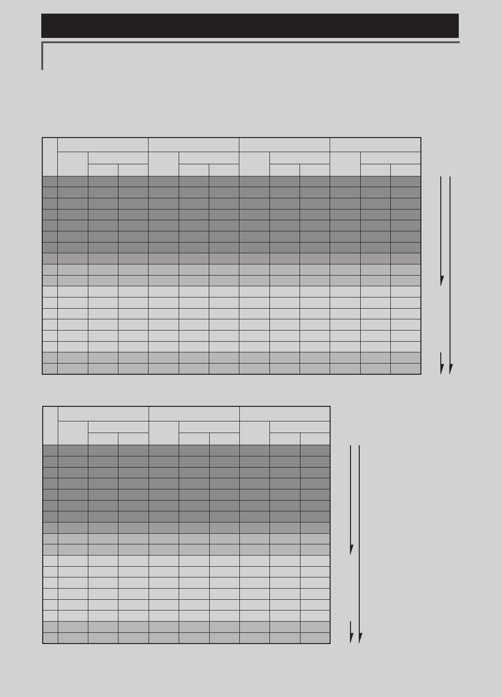
117
<Model Menu (Airplane/Glider Functions) >
Reference FMT-03 is equipped with a stick of multi-copter exclusive use. Therefore it's
unsuitable for use of an airplane, a glider and a helicopter.
RX
CH
1AIL 2AIL 2AIL+1FLAP 2AIL+2FLAP
Airplane Glider Airplane Glider Airplane Glider Airplane Glider
EP EP EP EP
1 Aileron Aileron Aileron Aileron Aileron Aileron Aileron Aileron Aileron Aileron Aileron Aileron
2Elevator Elevator Elevator Elevator Elevator Elevator Elevator Elevator Elevator Elevator Elevator Elevator
3 Throttle Motor AUX7 Throttle Motor AUX7 Throttle Motor AUX7 Throttle Motor AUX7
4Rudder Rudder Rudder Rudder Rudder Rudder Rudder Rudder Rudder Rudder Rudder Rudder
5Gear AUX6 AUX6 Gear AUX6 AUX6 Elevator2 Elevator2 Elevator2 Elevator2 Elevator2 Elevator2
6 Airbrake Airbrake Airbrake Aileron2 Aileron2 Aileron2 Aileron2 Aileron2 Aileron2 Aileron2 Aileron2 Aileron2
7 Elevator2 Elevator2 Elevator2 Elevator2 Elevator2 Elevator2 Flap Flap Flap Flap Flap Flap
8AUX5 AUX5 AUX5 AUX5 AUX5 AUX5 Gear AUX6 AUX6 Flap2 Flap2 Flap2
9AUX4 AUX4 AUX4 AUX4 AUX4 AUX4 AUX5 AUX5 AUX5 Gear AUX6 AUX6
10 AUX3 AUX3 AUX3 AUX3 AUX3 AUX3 AUX4 AUX4 AUX4 AUX5 AUX5 AUX5
11 AUX2 AUX2 AUX2 AUX2 AUX2 AUX2 AUX3 AUX3 AUX3 AUX4 AUX4 AUX4
12 AUX1 AUX1 AUX1 AUX1 AUX1 AUX1 AUX2 AUX2 AUX2 AUX3 AUX3 AUX3
13 AUX1 AUX1 AUX1 AUX1 AUX1 AUX1 AUX1 AUX1 AUX1 AUX2 AUX2 AUX2
14 AUX1 AUX1 AUX1 AUX1 AUX1 AUX1 AUX1 AUX1 AUX1 AUX1 AUX1 AUX1
15 AUX1 AUX1 AUX1 AUX1 Buttery Buttery AUX1 Buttery Buttery AUX1 Buttery Buttery
16 AUX1 AUX1 AUX1 Camber Camber Camber Camber Camber Camber Camber Camber Camber
DG1 SW SW SW SW SW SW SW SW SW SW SW SW
DG2 SW SW SW SW SW SW SW SW SW SW SW SW
RX
CH
2AIL+4FLAP 4AIL+2FLAP 4AIL+4FLAP
Airplane Glider Airplane Glider Airplane Glider
EP EP EP
1 Aileron Aileron Aileron Aileron Aileron Aileron Aileron Aileron Aileron
2Elevator Elevator Elevator Elevator Elevator Elevator Elevator Elevator Elevator
3 Throttle Motor AUX7 Throttle Motor AUX7 Throttle Motor AUX7
4Rudder Rudder Rudder Rudder Rudder Rudder Rudder Rudder Rudder
5Elevator2 Elevator2 Elevator2 Elevator2 Elevator2 Elevator2 Elevator2 Elevator2 Elevator2
6 Aileron2 Aileron2 Aileron2 Aileron2 Aileron2 Aileron2 Aileron2 Aileron2 Aileron2
7 Flap Flap Flap Aileron3 Aileron3 Aileron3 Aileron3 Aileron3 Aileron3
8Flap2 Flap2 Flap2 Aileron4 Aileron4
Aileron4
Aileron4 Aileron4
Aileron4
9Flap3 Flap3 Flap3
Flap Flap Flap Flap Flap Flap
10 Flap4 Flap4 Flap4
Flap2 Flap2
Flap2
Flap2 Flap2 Flap2
11 Gear AUX6 AUX6 Gear AUX6 AUX6 Flap3 Flap3
Flap3
12 AUX5 AUX5 AUX5 AUX5 AUX5 AUX5 Flap4 Flap4 Flap4
13 AUX4 AUX4 AUX4 AUX4 AUX4 AUX4 Gear AUX6 AUX6
14 AUX3 AUX3 AUX3 AUX3 AUX3 AUX3 AUX5 AUX5 AUX5
15 AUX2 Buttery Buttery AUX2 Buttery Buttery AUX4 Buttery Buttery
16 Camber Camber Camber Camber Camber Camber Camber Camber Camber
DG1 SW SW SW SW SW SW SW SW SW
DG2 SW SW SW SW SW SW SW SW SW
●Ailevator
FASSTest 12CH
FASSTest 18CH
The output
CH of each
system
FASSTest 12CH
FASSTest 18CH
The output
CH of each
system

118 <Model Menu (Airplane/Glider Functions) >
Reference FMT-03 is equipped with a stick of multi-copter exclusive use. Therefore it's
unsuitable for use of an airplane, a glider and a helicopter.
●Tailless wing
RX
CH
2AIL 2AIL+1FLAP 2AIL+2FLAP
Airplane Glider Airplane Glider Airplane Glider
EP EP EP
1 Aileron Aileron Aileron Aileron Aileron Aileron Aileron Aileron Aileron
2AUX4 AUX4 AUX4 AUX4 AUX4 AUX4 AUX4 AUX4 AUX4
3 Throttle Motor AUX7 Throttle Motor AUX7 Throttle Motor AUX7
4Rudder Rudder Rudder Rudder Rudder Rudder Rudder Rudder Rudder
5Gear AUX6 AUX6 Gear AUX6 AUX6 Aileron2 Aileron2 Aileron2
6 Aileron2 Aileron2 Aileron2 Aileron2 Aileron2 Aileron2 Flap Flap Flap
7 AUX5 AUX5 AUX5 Flap Flap Flap Flap2 Flap2 Flap2
8AUX3 AUX3 AUX3 AUX5 AUX5 AUX5 Gear AUX6 AUX6
9AUX2 AUX2 AUX2 AUX3 AUX3 AUX3 AUX5 AUX5 AUX5
10 AUX1 AUX1 AUX1 AUX2 AUX2 AUX2 AUX3 AUX3 AUX3
11 AUX1 AUX1 AUX1 AUX1 AUX1 AUX1 AUX2 AUX2 AUX2
12 AUX1 AUX1 AUX1 AUX1 AUX1 AUX1 AUX1 AUX1 AUX1
13 AUX1 AUX1 AUX1 AUX1 AUX1 AUX1 AUX1 AUX1 AUX1
14 AUX1 AUX1 AUX1 AUX1 Buttery Buttery AUX1 Buttery Buttery
15 Camber Camber Camber Camber Camber Camber Camber Camber Camber
16 Elevator Elevator Elevator Elevator Elevator Elevator Elevator Elevator Elevator
DG1 SW SW SW SW SW SW SW SW SW
DG2 SW SW SW SW SW SW SW SW SW
RX
CH
2AIL+4FLAP 4AIL+2FLAP 4AIL+4FLAP
Airplane Glider Airplane Glider Airplane Glider
EP EP EP
1 Aileron Aileron Aileron Aileron Aileron Aileron Aileron Aileron Aileron
2Aileron2 Aileron2 Aileron2 Aileron2 Aileron2 Aileron2 Aileron2 Aileron2 Aileron2
3 Throttle Motor AUX7 Throttle Motor
AUX7
Throttle Motor
AUX7
4Rudder Rudder Rudder Rudder Rudder Rudder Rudder Rudder Rudder
5Flap Flap Flap Aileron3 Aileron3 Aileron3 Aileron3 Aileron3 Aileron3
6 Flap2 Flap2 Flap2 Aileron4 Aileron4 Aileron4 Aileron4 Aileron4 Aileron4
7 Flap3 Flap3 Flap3 Flap
Flap
Flap
Flap Flap
Flap
8Flap4 Flap4 Flap4 Flap2 Flap2 Flap2 Flap2 Flap2 Flap2
9AUX4 AUX4 AUX4 AUX4 AUX4 AUX4
Flap3 Flap3 Flap3
10 Gear AUX6 AUX6 Gear AUX6 AUX6 Flap4 Flap4 Flap4
11 AUX5 AUX5 AUX5 AUX5 AUX5 AUX5 AUX4 AUX4 AUX4
12 AUX3 AUX3 AUX3 AUX3 AUX3 AUX3 Gear AUX6 AUX6
13 AUX2 AUX2 AUX2 AUX2 AUX2 AUX2 AUX5 AUX5 AUX5
14 AUX1 Buttery Buttery AUX1 Buttery Buttery AUX3 Buttery Buttery
15 Camber Camber Camber Camber Camber Camber Camber Camber Camber
16 Elevator Elevator Elevator Elevator Elevator Elevator Elevator Elevator Elevator
DG1 SW SW SW SW SW SW SW SW SW
DG2 SW SW SW SW SW SW SW SW SW
FASSTest 12CH
FASSTest 18CH
The output
CH of each
system
FASSTest 12CH
FASSTest 18CH
The output
CH of each
system
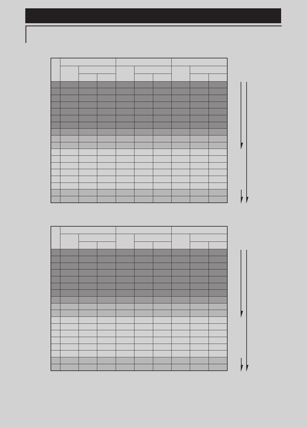
119
<Model Menu (Airplane/Glider Functions) >
Reference FMT-03 is equipped with a stick of multi-copter exclusive use. Therefore it's
unsuitable for use of an airplane, a glider and a helicopter.
●Tailless wing Winglet 2Rudder
RX
CH
2AIL 2AIL+1FLAP 2AIL+2FLAP
Airplane Glider Airplane Glider Airplane Glider
EP EP EP
1 Aileron Aileron Aileron Aileron Aileron Aileron Aileron Aileron Aileron
2RUD2 RUD2 RUD2 RUD2 RUD2 RUD2 RUD2 RUD2 RUD2
3 Throttle Motor AUX7 Throttle Motor AUX7 Throttle Motor AUX7
4Rudder Rudder Rudder Rudder Rudder Rudder Rudder Rudder Rudder
5Gear AUX6 AUX6 Gear AUX6 AUX6 Aileron2 Aileron2 Aileron2
6 Aileron2 Aileron2 Aileron2 Aileron2 Aileron2 Aileron2 Flap Flap Flap
7 AUX5 AUX5 AUX5 Flap Flap Flap Flap2 Flap2 Flap2
8AUX3 AUX3 AUX3 AUX5 AUX5 AUX5 Gear AUX6 AUX6
9AUX2 AUX2 AUX2 AUX3 AUX3 AUX3 AUX5 AUX5 AUX5
10 AUX1 AUX1 AUX1 AUX2 AUX2 AUX2 AUX3 AUX3 AUX3
11 AUX1 AUX1 AUX1 AUX1 AUX1 AUX1 AUX2 AUX2 AUX2
12 AUX1 AUX1 AUX1 AUX1 AUX1 AUX1 AUX1 AUX1 AUX1
13 AUX1 AUX1 AUX1 AUX1 AUX1 AUX1 AUX1 AUX1 AUX1
14 AUX1 AUX1 AUX1 AUX1 Buttery Buttery AUX1 Buttery Buttery
15 Camber Camber Camber Camber Camber Camber Camber Camber Camber
16 Elevator Elevator Elevator Elevator Elevator Elevator Elevator Elevator Elevator
DG1 SW SW SW SW SW SW SW SW SW
DG2 SW SW SW SW SW SW SW SW SW
RX
CH
2AIL+4FLAP 4AIL+2FLAP 4AIL+4FLAP
Airplane Glider Airplane Glider Airplane Glider
EP EP EP
1 Aileron Aileron Aileron Aileron Aileron Aileron Aileron Aileron Aileron
2Aileron2 Aileron2 Aileron2 Aileron2 Aileron2 Aileron2 Aileron2 Aileron2 Aileron2
3 Throttle Motor AUX7 Throttle Motor
AUX7
Throttle Motor
AUX7
4Rudder Rudder Rudder Rudder Rudder Rudder Rudder Rudder Rudder
5Flap Flap Flap Aileron3 Aileron3 Aileron3 Aileron3 Aileron3 Aileron3
6 Flap2 Flap2 Flap2 Aileron4 Aileron4 Aileron4 Aileron4 Aileron4 Aileron4
7 Flap3 Flap3 Flap3 Flap
Flap
Flap
Flap Flap
Flap
8Flap4 Flap4 Flap4 Flap2 Flap2 Flap2 Flap2 Flap2 Flap2
9RUD2 RUD2 RUD2 RUD2 RUD2 RUD2
Flap3 Flap3 Flap3
10 Gear AUX6 AUX6 Gear AUX6 AUX6 Flap4 Flap4 Flap4
11 AUX5 AUX5 AUX5 AUX5 AUX5 AUX5 RUD2 RUD2 RUD2
12 AUX3 AUX3 AUX3 AUX3 AUX3 AUX3 Gear AUX6 AUX6
13 AUX2 AUX2 AUX2 AUX2 AUX2 AUX2 AUX5 AUX5 AUX5
14 AUX1 Buttery Buttery AUX1 Buttery Buttery AUX3 Buttery Buttery
15 Camber Camber Camber Camber Camber Camber Camber Camber Camber
16 Elevator Elevator Elevator Elevator Elevator Elevator Elevator Elevator Elevator
DG1 SW SW SW SW SW SW SW SW SW
DG2 SW SW SW SW SW SW SW SW SW
* Output channels differ by each system of a table. When using a system with few channels,
there is a wing type which cannot be used. It cannot be used when there is a function
required out of the range of the arrow of a gure.
FASSTest 12CH
FASSTest 18CH
The output
CH of each
system
FASSTest 12CH
FASSTest 18CH
The output
CH of each
system
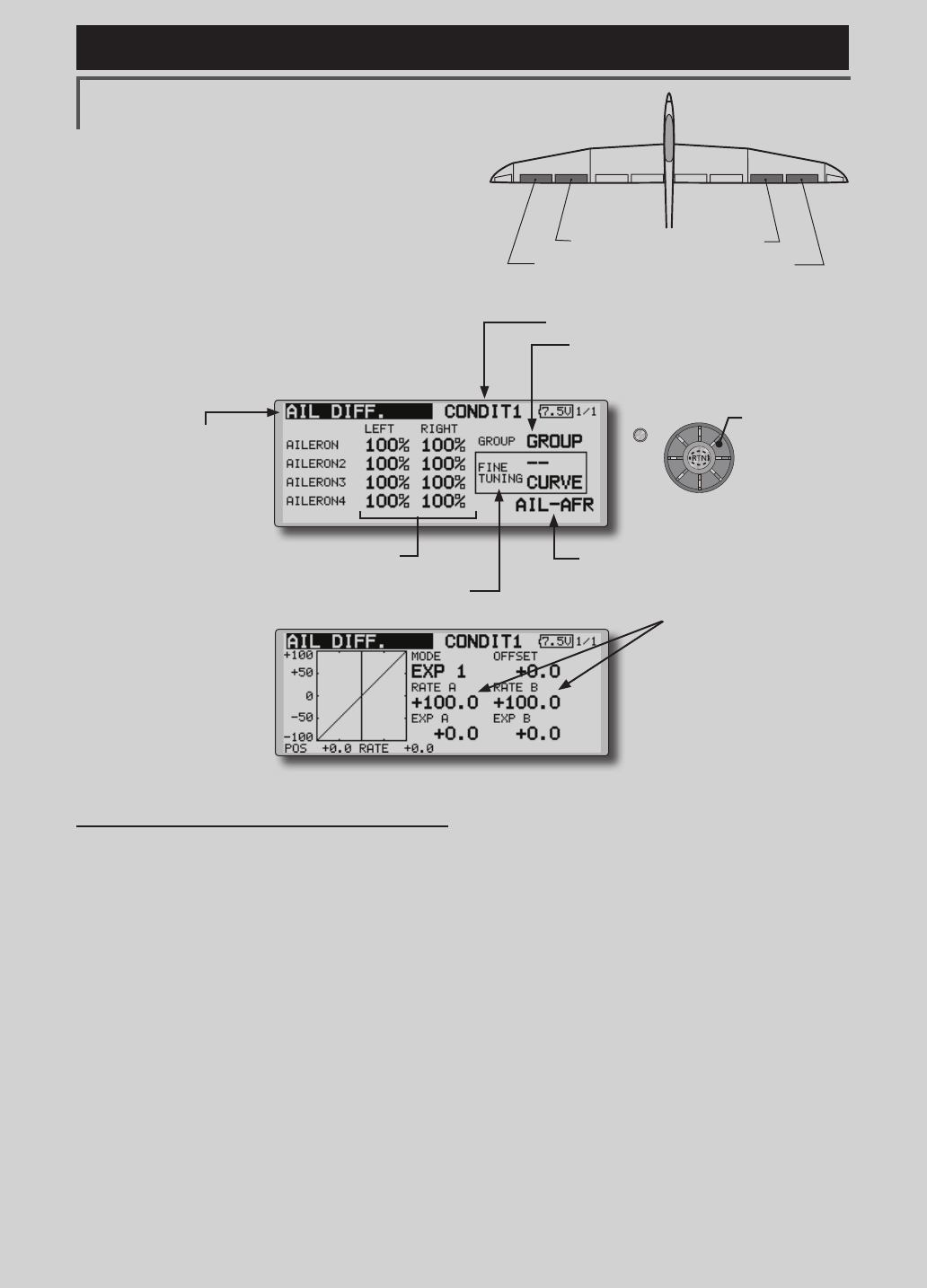
120 <Model Menu (Airplane/Glider Functions) >
Reference FMT-03 is equipped with a stick of multi-copter exclusive use. Therefore it's
unsuitable for use of an airplane, a glider and a helicopter.
S1
●Selectthefunction
nameandreturntothe
precedingscreenby
pushingtheRTNbutton
orpushingtheHome/Exit
button.
<Editdial>
AIL 3
(Chip Aileron) AIL 4
(Chip Aileron)
AIL1
(Main Aileron) AIL 2
(Main Aileron)
AIL DIFF. [Airplane/glider,2aileronsormore]
The left and right aileron differential can be
adjusted independently. The differential rate can
also be adjusted according to the flying state by
setting a ne tuning VR.
●CallstheAFR screendirectlywhen
adjustingaileronoperationAFR.
●FinetuningVRsetting
*The graph is operated by setting a VR, etc.
●Group/singlemodeswitching
(For more information, refer to the description at
the back of this manual.)
●Aileronleft/rightadjustment
<Wing type: 4 ailerons screen>
*The display screen is an example. The actual screen
depends on the Model Type.
●OveralladjustmentbyRate
AandRateB.
Setting method
●Movethecursortotheaileron(AIL)1~4left(or
right)settingitemandpushtheRTNbuttonto
switchtothedatainputmode.
Adjusttheaileronangleswhenthestickis
movedtotheleft(orright)end.
PushtheRTNbuttontoendadjustmentand
returntothecursormovemode.
*The aileron AFR screen can be directly called from the AIL
differential setup screen. ([AIL-AFR] )
●WhensettingthefinetuningVR,movethe
cursortothe"--"itemandpushtheRTN
buttontocalltheselectionscreen,andthen
selectthenetuningVR.
PushtheRTNbuttontoendadjustmentand
returntothecursormovemode.
●Thenetuningratecanbesetbycurve.
(Currently selected condition name)
●Select[AILDIFF.]atthemodelmenuandcall
thesetupscreenshown below by pushing
theRTNbutton.
Scrolling
●Movingcursor
●Selectingmode
●Adjustingvalue