Contents
- 1. User Manual 1
- 2. User Manual 2
- 3. User Manual 3
User Manual 3
121
<Model Menu (Airplane/Glider Functions) >
Reference FMT-03 is equipped with a stick of multi-copter exclusive use. Therefore it's
unsuitable for use of an airplane, a glider and a helicopter.
S1
●Selectthefunction
nameandreturntothe
precedingscreenby
pushingtheRTNbutton
orpushingtheHome/Exit
button.
<Editdial>
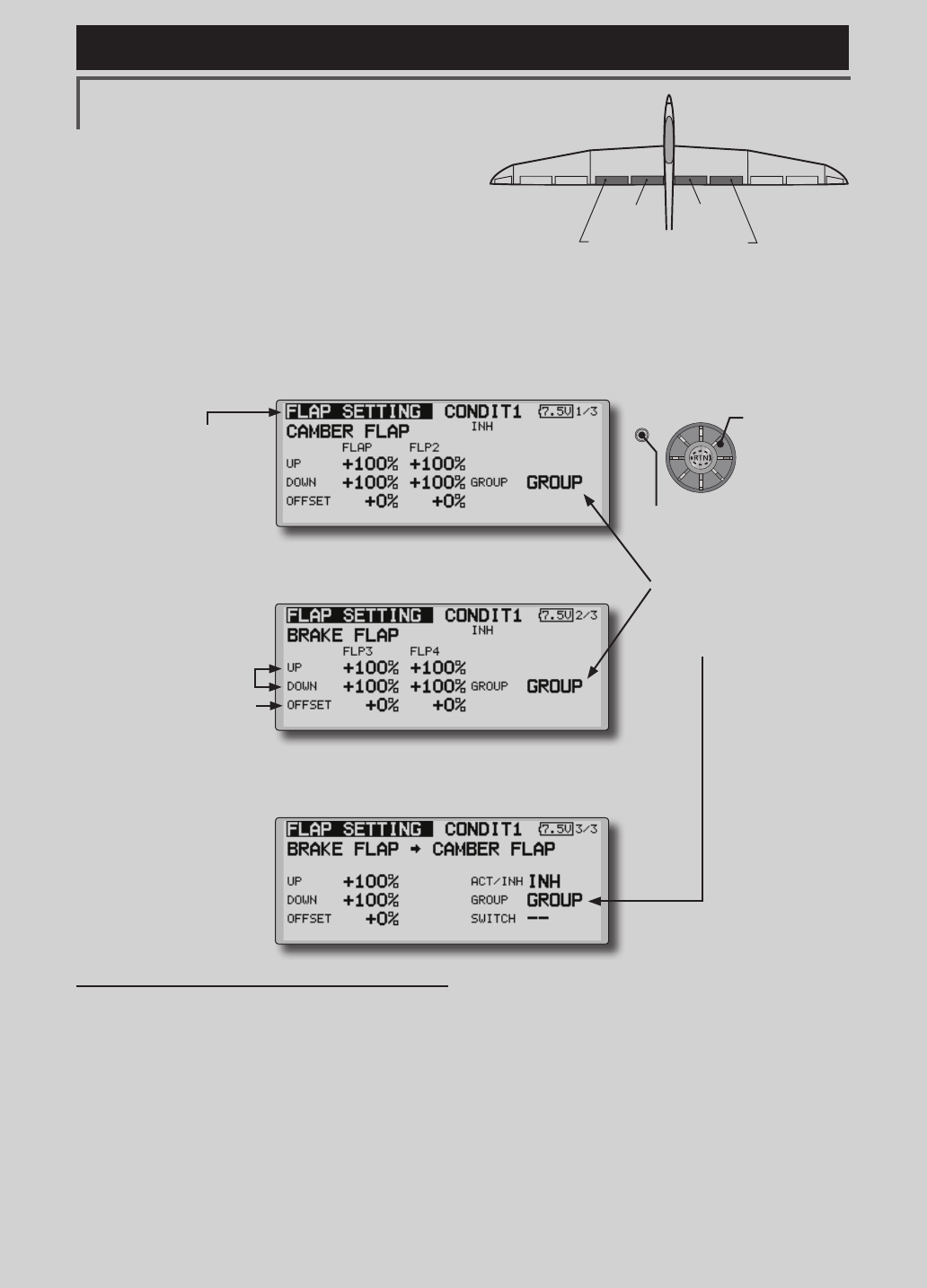
FLP 2
(Camber Flap)
FLP 1
(Camber Flap)
FLP 3
(Brake Flap) FLP 4
(Brake Flap)
FLAP SETTING [Correspondingmodeltype]:Airplane/
glider,2apsormore]
The up/down travel of each flap (camber flaps:
FLP1/2, brake flaps: FLP3/4) can be adjusted
independently at each servo according to the wing type.
●Theoperationreferencepointofeachapcanbe
offset
The camber aps of a 4-ap model can be mixed
with the brake aps. (Brake FLP to camber FLP)
●AnON/OFFswitchcanbeset. <Wing type: 4 aps screen>
*The display screen is an example. The actual
screen depends on the model type.
Setting method
●Movethecursortotheflap(FLP)1~4upor
downitemaccordingtothewingtypeand
pushtheRTNbuttontoswitchtothedata
inputmode.
Adjustthetravelindependently.
●Tooffsettheoperationreferencepoint
ofeachflap,movethecursortothe
correspondingoffsetitem.Usetheeditdial
tooffsetthereferencepoint.
PushtheRTNbuttontoendadjustmentand
returntothecursormovemode.
●Operationreference
pointoffset
●Upside/Downside
adjustment
●Group/singlemodeswitching
(For more information, refer to
the description at the back of this
manual.)
●WhenusingbrakeFLPtocamberFLPmixing,
movethecursortothe[ACT/INH]itemand
turntheeditdialtotheleftandpushtheRTN
button.(ONisdisplayed.)
Whensettingaswitch,movethecursorto
the[--]itemoftheswitchandpushtheRTN
buttontocalltheselectionscreen,andthen
selecttheswitchandsetitsONdirection.
(AlwaysONat"--"setting)
(Foradescriptionoftheswitchselection
method,seethedescriptionatthebackof
thismanual.)
(CAMBERFLPsettingscreen)
(BRAKEFLPsettingscreen)
(B.FLPtoC.FLPsettingscreen)
●Select[FLAPSETTING]atthemodelmenuandcallthe
setupscreenshownbelowbypushingtheRTNbutton.
Scrolling
●Movingcursor
●Selectingmode
●Adjustingvalue
●PushtheS1button
tocallnextpage.
122 <Model Menu (Airplane/Glider Functions) >
Reference FMT-03 is equipped with a stick of multi-copter exclusive use. Therefore it's
unsuitable for use of an airplane, a glider and a helicopter.
S1
●Selectthefunction
nameandreturntothe
precedingscreenby
pushingtheRTNbutton
orpushingtheHome/Exit
button.
<Editdial>
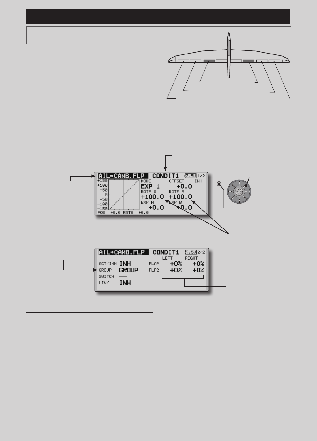
AIL 3
(Chip Aileron) AIL 4
(Chip Aileron)
AIL1
(Main Aileron) AIL 2
(Main Aileron)
FLP 2
(Camber Flap)
FLP 1
(Camber Flap)
AIL to CAMB.FLP [Correspondingmodeltype]:Airplane/
glider,2ailerons+2apsormore
This mix operates the camber flaps (FLP1/2)
in the aileron mode. When the aileron stick
is manipulated, the ailerons and camber flaps
perform aileron operation simultaneously and
the operation characteristic of the roll axis is
improved.
●Theaileronleft/rightmixingrateofeachapservo
canbene-tuned.
●Amixingcurvecanbeset.
●AnON/OFFswitchcanbeset.
●Linkingispossible:Linkthismixtoothermixes.
●Mixingcurvesetting
*For a description of the curve setting method, see the
description at the back of this manual.
●Adjustmentofeach
apservo
●Left/rightoverall
adjustmentatRate
AandRateB
Setting method
●MovethecursortotheACT/INHitemand
pushtheRTNbuttontoswitchtothedata
inputmode.
TurntheeditdialtotheleftandpushtheRTN
button.(ONisdisplayed.)
●Whensettingaswitch,movethecursorto
the[--]itemoftheswitchandpushtheRTN
buttontocalltheselectionscreen,andthen
selecttheswitchandsetitsONdirection.
(AlwaysONat"--"setting)
(Foradescriptionoftheswitchselection
method,seethedescriptionatthebackof
thismanual.)
●Movethecursortotheleftorrightitemof
eachapservoandpushtheRTNbutton to
switchtothedatainputmode.
Adjustthemixingratewiththeeditdial.
PushtheRTNbuttontoendadjustmentand
returntothecursormovemode.
*When the mixing direction is reversed by the linkage,
adjustments can be made by changing the mixing rate
polarity (+ or -).
●Amixingcurvecanbeset.
(Foradescriptionofthemixingcurvesetting
method,seethedescriptionatthebackof
thismanual.)
●Tosetlinking,movethecursortothe[LINK]
itemandpushtheRTNbuttontoswitchto
thedatainputmode.
SetittoONandpushtheRTNbutton.
(Currently selected condition name)
●Select[AILtoCAMB.FLP]atthemodelmenu
andcallthesetupscreenshownbelowby
pushingtheRTNbutton.
●Group/singlemodeswitching
(For more information, refer to
the description at the back of
this manual.)
*The display screen is an example. The actual
screen depends on the model type.
Scrolling
●Movingcursor
●Selectingmode
●Adjustingvalue
●PushtheS1button
tocallnextpage.
123
<Model Menu (Airplane/Glider Functions) >
Reference FMT-03 is equipped with a stick of multi-copter exclusive use. Therefore it's
unsuitable for use of an airplane, a glider and a helicopter.
S1
●Selectthefunction
nameandreturntothe
precedingscreenby
pushingtheRTNbutton
orpushingtheHome/Exit
button.
<Editdial>
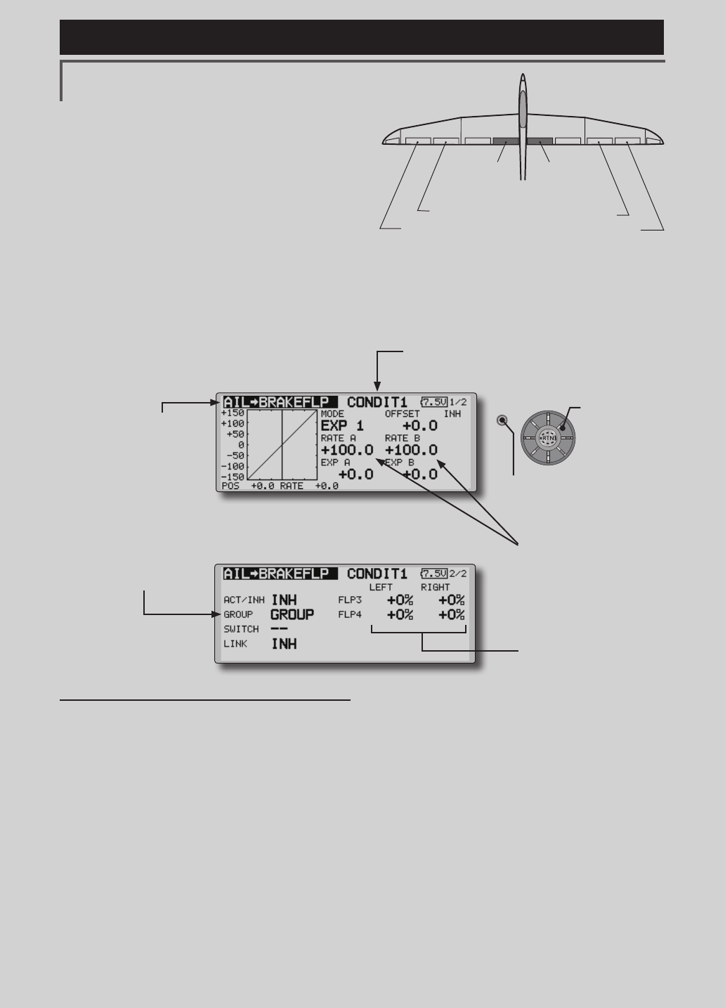
AIL 3
(Chip Aileron) AIL 4
(Chip Aileron)
AIL1
(Main Aileron) AIL 2
(Main Aileron)
FLP 3
(Brake Flap) FLP 4
(Brake Flap)
AIL to BRAKEFLP [Correspondingmodeltype]:Airplane/
glider,4apsormore
This mix operates the brake flaps (FLP3/4)
in the aileron mode. When the aileron stick
is manipulated, the aileron and brake flaps
perform the aileron operation simultaneously
and the operation characteristic of the roll axis is
improved.
●Theaileronleftandrightmixingratescanbe
adjustedforeachapservo.
●Amixingcurvecanbeset.
●MixingduringightcanbeturnedON/OFFby
settingaswitch.(AlwaysONat[--]setting)
●Linkingcanbeset:Linkthismixtoothermixes.
●Setting method
●MovethecursortotheACT/INHitemand
pushtheRTNbuttontoswitchtothedata
inputmode.
TurntheeditdialtotheleftandpushtheRTN
button.(ONisdisplayed.)
●Whensettingaswitch,movethecursorto
the[--]itemoftheswitchandpushtheRTN
buttontocalltheselectionscreen,andthen
selecttheswitchandsetitsONdirection.
(AlwaysONat"--"setting)
(Foradescriptionoftheswitchselection
method,seethedescriptionatthebackof
thismanual.)
●Movethecursortotheleftorrightbuttonof
eachapservoandpushtheRTNbutton to
switchtothedatainputmode.
Adjustthemixingratewiththeeditdial.
PushtheRTNbuttontoendadjustmentand
returntothecursormovemode.
*When the mixing direction is reversed by the linkage,
adjustments can be made by reversing the mixing rate
polarity (+ or -).
●Amixingcurvecanbeset.
(Foradescriptionofthecurvesetting
method,seethedescriptionatthebackof
thismanual.)
●Tosetlinking,movethecursortotheLinkitem
andpushtheRTNbuttontoswitchtothe
datainputmode.
SetittoONandpushtheRTNbutton.
●Mixingcurvesetting
*For a description of the curve setting method, see the
description at the back of this manual.
●Adjustmentofeachap
servo
●Left/rightoverall
adjustmentatRateA
andRateB
(Currently selected condition name)
●Select[AILtoBRAKEFLP]atthemodelmenuand
callthesetupscreenshownbelowbypushingthe
RTNbutton.
●Group/singlemode
switching
(For more information, refer
to the description at the
back of this manual.)
*The display screen is an example. The actual screen
depends on the model type.
Scrolling
●Movingcursor
●Selectingmode
●Adjustingvalue
●PushtheS1button
tocallnextpage.
124 <Model Menu (Airplane/Glider Functions) >
Reference FMT-03 is equipped with a stick of multi-copter exclusive use. Therefore it's
unsuitable for use of an airplane, a glider and a helicopter.
S1
●Selectthefunction
nameandreturntothe
precedingscreenby
pushingtheRTNbutton
orpushingtheHome/Exit
button.
<Editdial>
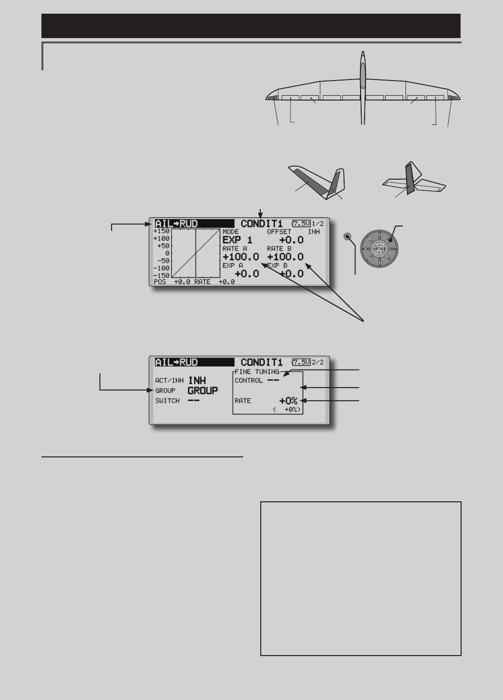
RUDDER 2
RUDDER RUDDER
V-TAIL
RUDDER 2
Winglet
RUDDER 1
Winglet
at Flying wing at Flying wing
( ) ( )
AIL 3 AIL 3
(Chip Aileron) (Chip Aileron)
AIL1
(Main Aileron) AIL 2
(Main Aileron)
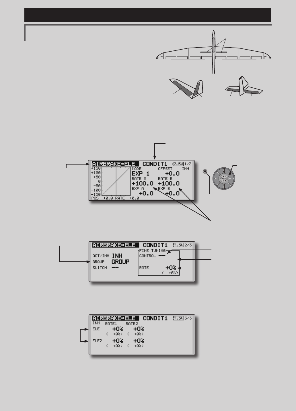
AIL to RUD [Correspondingmodeltype]:
Airplane/glider,general
Use this mix when you want to mix the rudders
with aileron operation.
●Amixingcurvecanbeset.
●MixingduringightcanbeturnedON/OFFby
settingaswitch.(AlwaysONat[--]setting)
●Themixingratecanbene-tunedbysettingaVR.
Setting method
●MovethecursortotheACT/INHitemand
pushtheRTNbuttontoswitchtothedata
inputmode.
TurntheeditdialtotheleftandpushtheRTN
button.(ONisdisplayed.)
●Whensettingaswitch,movethecursorto
the[--]itemoftheswitchandpushtheRTN
buttontocalltheselectionscreen,andthen
selecttheswitchandsetitsONdirection.
(AlwaysONat"--"setting)
(Foradescriptionoftheswitchselection
method,seethedescriptionatthebackof
thismanual.
●WhensettingaVR,movethecursortothe
FineTuning"--"itemandpushtheRTNbutton
tocalltheselectionscreen,andthenselect
theVR.Theadjustmentratecanbeset.The
VRoperationmodecanalsobeselected.
[FinetuningVRoperationmode]
[LIN.] Mixingrate0%atcenterofVR.
WhentheVRisturnedclockwiseand
counterclockwise,themixingrate
increasesanddecreases,respectively.
[ATL+]Mixingrate0%atleftendofVR.
WhentheVRisturned,themixingrate
increases.
[ATL-] Mixingrate0%at rightendofVR.
WhentheVRisturned,themixingrate
increases.
[SYM.]WhentheVRisturnedtotheleftor
rightoftheneutralposition,themixing
rateincreases.
●Mixingcurvesetting
*For a description of the curve setting method, see the
description at the back of this manual. ●Left/rightoveralladjustment
atRateAandRateB
(Currently selected condition name)
●Select[AILtoRUD]atthemodelmenu and
callthesetupscreenshownbelowbypushing
theRTNbutton.
●Group/singlemode
switching
(For more information, refer
to the description at the
back of this manual.)
*The display screen is an
example. The actual screen
depends on the model type.
●FinetuningVRsetting
●Adjustmentrate
●Operationmode
●Amixingcurvecanbeset.
(Foradescriptionofthecurvesetting
method,seethedescriptionatthebackof
thismanual.)
Scrolling
●Movingcursor
●Selectingmode
●Adjustingvalue
●PushtheS1button
tocallnextpage.
125
<Model Menu (Airplane/Glider Functions) >
Reference FMT-03 is equipped with a stick of multi-copter exclusive use. Therefore it's
unsuitable for use of an airplane, a glider and a helicopter.
S1
●Selectthefunction
nameandreturntothe
precedingscreenby
pushingtheRTNbutton
orpushingtheHome/Exit
button.
<Editdial>
ELEVATOR ELEVATOR 2
AILVATOR
AIR BRAKE
V-TAIL
ELEVATOR ELEVATOR 2
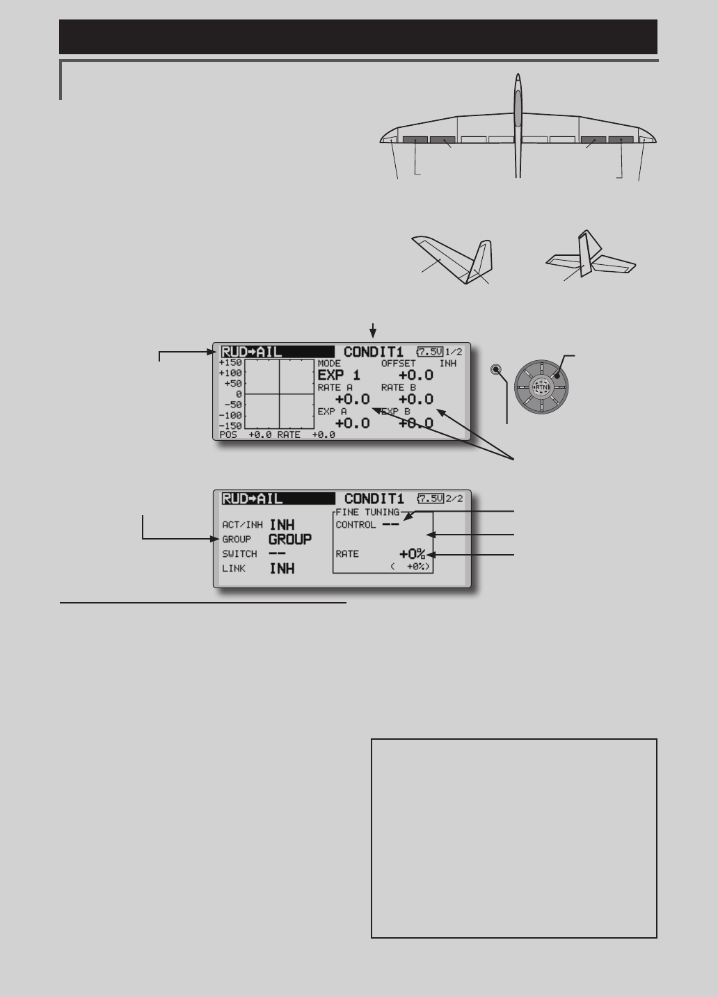
AIRBRAKE to ELE [Correspondingmodeltype]:
Airplane/glider,general
This mix is used when you want to mix the
elevators with airbrake (spoiler) operation. It
raises the elevators to correct for dropping of the
nose during airbrake operation.
*This function does not operate when airbrake is not assigned
at the Function menu in the Linkage Menu.
●TheRate1side/Rate2sidemixingratewiththe
elevatorservoscanbeadjusted.
●Amixingcurvecanbeset.
●MixingduringightcanbeturnedON/OFFby
settingaswitch.(AlwaysONat[--]setting)
●Themixingratecanbene-tunedbysettingaVR.
●FinetuningVRsetting
●Group/singlemode
switching
(For more information, refer
to the description at the
back of this manual.)
●OveralladjustmentbyRate
AandRateB.
(Currently selected condition name)
●Select[AIRBRAKEtoELE]atthemodelmenu
andcallthesetupscreenshownbelowby
pushingtheRTNbutton.
●Mixingcurvesetting
*For a description of the curve setting method, see the
description at the back of this manual.
●Adjustmentrate
●Operationmode
●Adjustmentofeach
elevatorservo
*The display screen is an example. The actual
screen depends on the model type.
Scrolling
●Movingcursor
●Selectingmode
●Adjustingvalue
●PushtheS1button
tocallnextpage.

126 <Model Menu (Airplane/Glider Functions) >
Reference FMT-03 is equipped with a stick of multi-copter exclusive use. Therefore it's
unsuitable for use of an airplane, a glider and a helicopter.
Setting method
●MovethecursortotheACT/INHitemand
pushtheRTNbuttontoswitchtothedata
inputmode.
TurntheeditdialtotheleftandpushtheRTN
button.(ONisdisplayed.)
●Whensettingaswitch,movethecursorto
the[--]itemoftheswitchandpushtheRTN
buttontocalltheselectionscreen,andthen
selecttheswitchandsetitsONdirection.
(AlwaysONat"--"setting)
(Foradescriptionoftheswitchselection
method,seethedescriptionatthebackof
thismanual.
●WhensettingaVR,movethecursortothe
Finetuning"--"itemandpushtheRTNbutton
tocalltheselectionscreen,andthenselect
theVR.Theadjustmentratecanbeset.The
VRoperationmodecanalsobeset.
(ForadescriptionofthenetuningVRsetting
method,seethedescriptionatthebackof
thismanual.)
●Amixingcurvecanbeset.
(Foradescriptionofthecurvesetting
method,seethedescriptionatthebackof
thismanual.)
[FinetuningVRoperationmode]
[LIN.] Mixingrate0%atcenterofVR.
WhentheVRisturnedclockwiseand
counterclockwise,themixingrate
increasesanddecreases,respectively.
[ATL+]Mixingrate0%atleftendofVR.
WhentheVRisturned,themixingrate
increases.
[ATL-] Mixingrate0%at rightendofVR.
WhentheVRisturned,themixingrate
increases.
[SYM.]WhentheVRisturnedtotheleftor
rightoftheneutralposition,themixing
rateincreases.
127
<Model Menu (Airplane/Glider Functions) >
Reference FMT-03 is equipped with a stick of multi-copter exclusive use. Therefore it's
unsuitable for use of an airplane, a glider and a helicopter.
S1
●Selectthefunction
nameandreturntothe
precedingscreenby
pushingtheRTNbutton
orpushingtheHome/Exit
button.
<Editdial>
RUDDER 2
RUDDER RUDDER
V-TAIL
RUDDER 2
Winglet
RUDDER 1
Winglet
at Flying wing at Flying wing
( ) ( )
AIL 3 AIL 3
(Chip Aileron) (Chip Aileron)
AIL1
(Main Aileron) AIL 2
(Main Aileron)
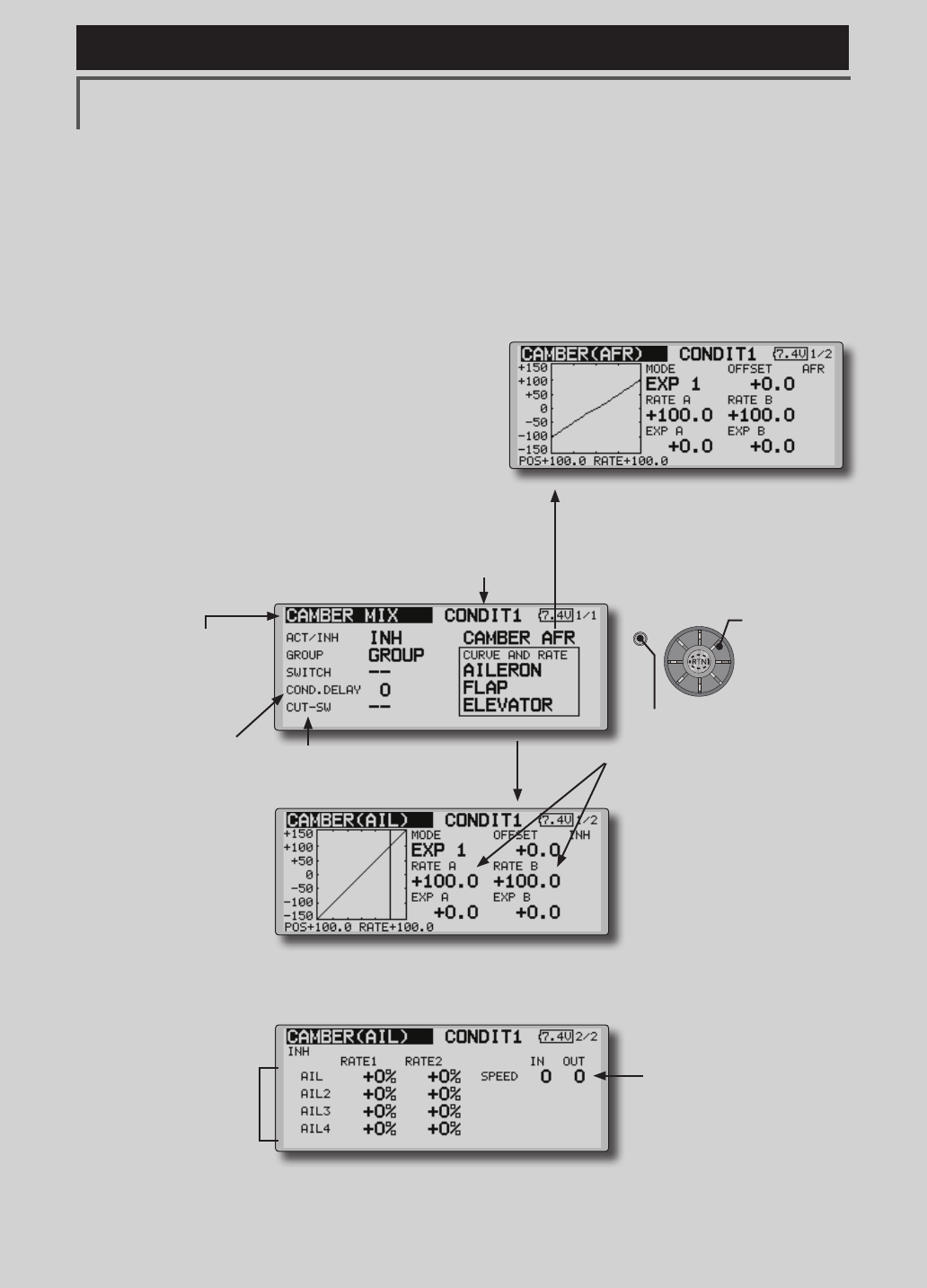
RUD to AIL [Correspondingmodeltype]:
Airplane/glider,general
This function is used when you want to mix
the ailerons with rudder operation. It is used
when rudder is applied during roll maneuvers,
knife edge, etc. of stunt planes. It can be used to
bank scale models, large models, etc. like a full
size plane.
●Amixingcurvecanbeset.
●MixingduringightcanbeturnedON/OFFby
settingaswitch.(AlwaysONat[--]setting)
●Linkingcanbeset:Linkthismixtoothermixes.
●Themixingratecanbene-tunebysettingaVR.
Setting method
●MovethecursortotheACT/INHitemand
pushtheRTNbuttontoswitchtothedata
inputmode.
TurntheeditdialtotheleftandpushtheRTN
button.(ONisdisplayed.)
●Whensettingaswitch,movethecursorto
the[--]itemoftheswitchandpushtheRTN
buttontocalltheselectionscreen,andthen
selecttheswitchandsetitsONdirection.
(AlwaysONat"--"setting)
(Foradescriptionoftheswitchselection
method,seethedescriptionatthebackof
thismanual.
●WhensettingaVR,movethecursortothe
Finetuning"--"itemandpushtheRTNbutton
tocalltheselectionscreenandthenselect
theVR.Theadjustmentratecanbeset,.
TheVRoperationmodecanalsobeset.
(ForadescriptionofthenetuningVRsetting
method,seethedescriptionatthebackof
thismanual.)
●Amixingcurvecanbeset.
(Foradescriptionofthecurvesetting
method,seethedescriptionatthebackof
thismanual.)
●Whenlinking:movethecursortothe[LINK]
itemandpushtheRTNbuttontoswitchto
thedatainputmode.Turntheeditdialto
theleftandpushtheRTNbutton.(ONis
displayed.)
●Mixingcurvesetting
*For a description of the curve setting method, see the
description at the back of this manual.
●Left/rightoveralladjustment
atRateAandRateB
(Currently selected condition name)
●Select[RUDtoAIL]atthemodel menu
andcallthesetupscreenshownbelowby
pushingtheRTNbutton.
●Group/singlemode
switching
(For more information,
refer to the description at
the back of this manual.)
*The display screen is an example. The
actual screen depends on the model type.
●FinetuningVRsetting
●Adjustmentrate
●Operationmode
[FinetuningVRoperationmode]
[LIN.] Mixingrate0%atcenterofVR.
WhentheVRisturnedclockwiseand
counterclockwise,themixingrate
increasesanddecreases,respectively.
[ATL+]Mixingrate0%atleftendofVR.
WhentheVRisturned,themixingrate
increases.
[ATL-] Mixingrate0%at rightendofVR.
WhentheVRisturned,themixingrate
increases.
[SYM.]WhentheVRisturnedtotheleftor
rightoftheneutralposition,themixing
rateincreases.
Scrolling
●Movingcursor
●Selectingmode
●Adjustingvalue
●PushtheS1button
tocallnextpage.
128 <Model Menu (Airplane/Glider Functions) >
Reference FMT-03 is equipped with a stick of multi-copter exclusive use. Therefore it's
unsuitable for use of an airplane, a glider and a helicopter.
S1
●Selectthefunction
nameandreturntothe
precedingscreenby
pushingtheRTNbutton
orpushingtheHome/Exit
button.
<Editdial>
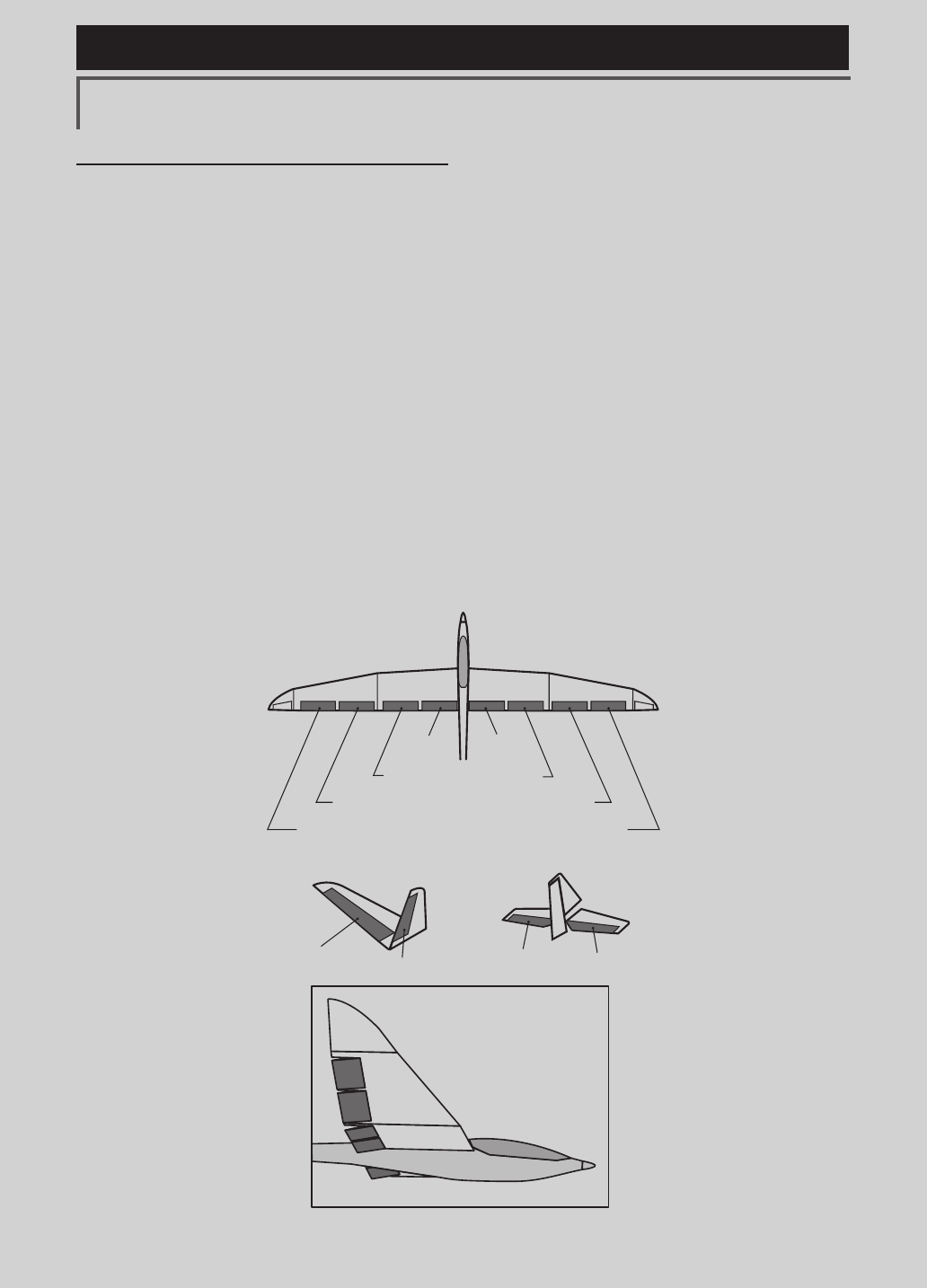
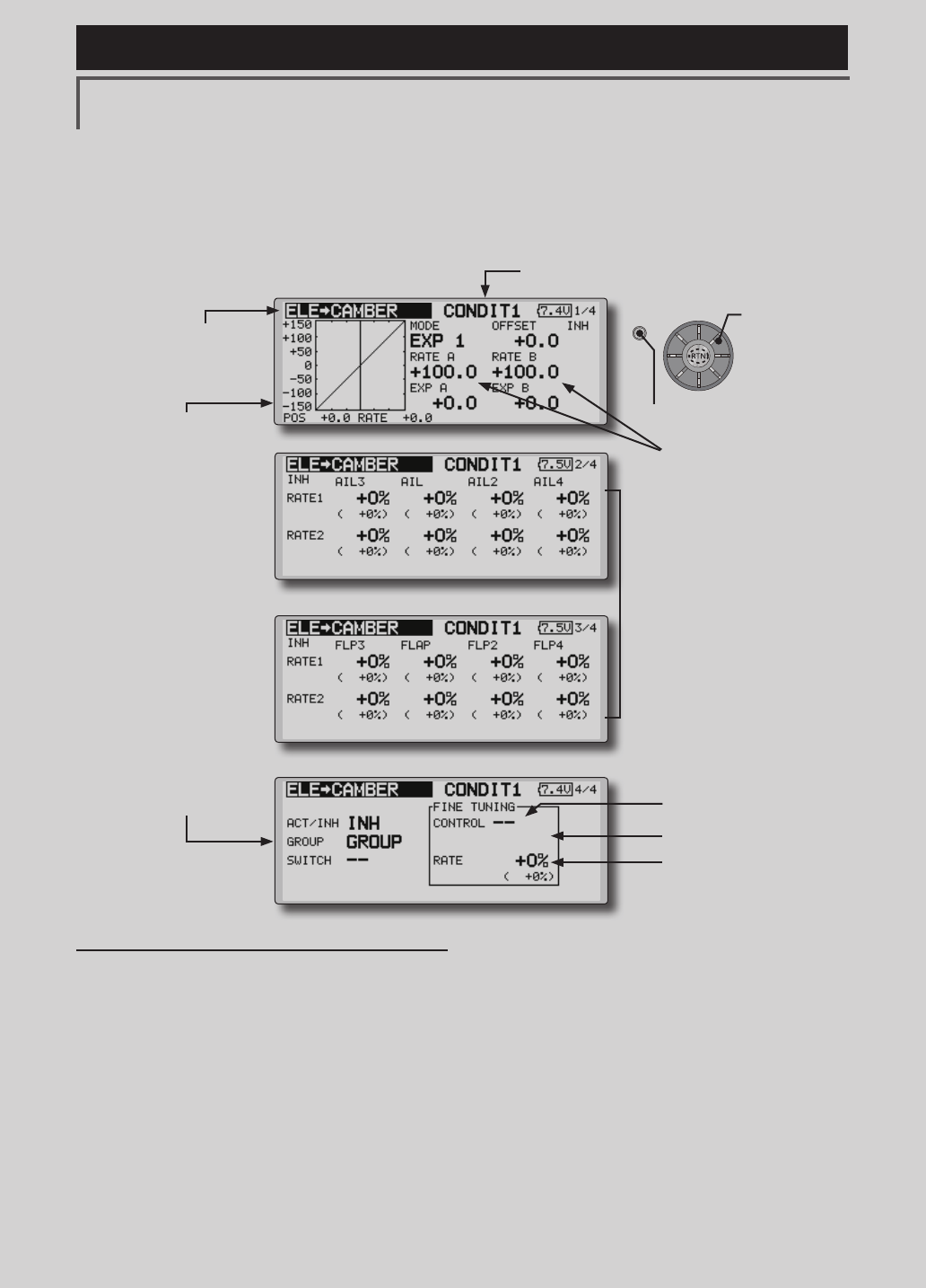
CAMBER MIX [Correspondingmodeltype]:Airplane/glider,2aileronsormore
This function adjusts the AFR (D/R) rate
of camber operation which operates the wing
camber (ailerons, camber flaps, brake flaps) in
the negative and positive directions. The aileron,
flap, and elevator rates can also be adjusted
independently by curve, and attitude changes
caused by camber operation can be corrected.
*Initial setting assigns camber operation to side lever LS.
●Theup/downsideratesoftheaileron,ap,and
elevatorservoscanbeadjustedbycurve.When
themixingdirectionisreversedbythelinkage,
adjustmentscanbemadebychangingthe
mixingratepolarity(+or-).
●MixingduringightcanbeturnedON/OFFby
settingaswitch.(AlwaysONat[--]setting)
●Adelaycanbesetforeachcondition.Acut
switchwhichcanturnOFFthedelayfunctioncan
beset.
●Thespeedoftheaileron,ap,andelevatorservos
canbeset.(INside/OUTside)
●Conditiondelaycut
switch
●Conditiondelay
setting
●CamberAFR(D/R)setupscreencall
(For a description of the setting method, refer to the
AFR function.)
●Servospeedsetting
(For a description of the setting
method, see the description at the
back of this manual.)
●OveralladjustmentbyRateA
andRateB
●Aileronrate
adjustment
(Currently selected condition name)
●Select[CAMBERMIX]atthemodelmenuand
callthesetupscreenshownbelowbypushing
theRTNbutton.
●Mixingcurvesetting
*For a description of the curve setting method, see the
description at the back of this manual.
*The display screen is an example. The actual screen
depends on the model type.
(Curve/ratesettingscreen)
Scrolling
●Movingcursor
●Selectingmode
●Adjustingvalue
●PushtheS1button
tocallnextpage.
129
<Model Menu (Airplane/Glider Functions) >
Reference FMT-03 is equipped with a stick of multi-copter exclusive use. Therefore it's
unsuitable for use of an airplane, a glider and a helicopter.
AIL 3
(Chip Aileron) AIL 4
(Chip Aileron)
AIL1
(Main Aileron) AIL 2
(Main Aileron)
FLP 2
(Camber Flap)
FLP 1
(Camber Flap)
ELEVATOR ELEVATOR 2
V-TAIL
ELEVATOR ELEVATOR 2
AILVATOR
FLP 3
(Brake Flap) FLP 4
(Brake Flap)
Setting method
●MovethecursortotheACT/INHitemand
pushtheRTNbuttontoswitchtothedata
inputmode.
TurntheeditdialtotheleftandpushtheRTN
button.(ONisdisplayed.)
●Whensettingaswitch,movethecursorto
the[--]itemoftheswitchandpushtheRTN
buttontocalltheselectionscreen,andthen
selecttheswitchandsetitsONdirection.
(AlwaysONat"--"setting)
(Foradescriptionoftheswitchselection
method,seethedescriptionatthebackof
thismanual.)
●Whensettingaconditiondelay,movethe
cursortothe[COND.DELAY]itemandpush
theRTNbuttontoswitchtothedatainput
mode.
Setthedelaywiththeeditdial.
PushtheRTNbuttontoendadjustmentand
returntothecursormovemode.
Whensettingacutswitch,movethecursor
to[CUT-SW]itemandpushtheRTNbuttonto
calltheselectionscreen,andthenselectthe
switchandsetitsONdirection.(AlwaysON
at[--]setting)
(Foradescriptionoftheconditiondelay
function,seethedescriptionatthebackof
thismanual.)
●CamberAFR(D/R)screencall
MovethecursortotheCamberAFRitemand
pushtheRTNbuttontocallthesetupscreen.
(Foradescriptionofthesetupmethod,see
thedescriptionatthebackofthismanual.)
(Curve/ratesetupscreen)
●Thecurveandrateareadjustedbycalling
theaileron,flap,andelevatorcurve/rate
screens.
Therateandcurveofeachservocanbeset
bycallingeachscreen.(Foradescriptionof
thecurvesettingmethod,seethedescription
atthebackofthismanual.)
Theservospeedcanalsobeadjusted.
130 <Model Menu (Airplane/Glider Functions) >
Reference FMT-03 is equipped with a stick of multi-copter exclusive use. Therefore it's
unsuitable for use of an airplane, a glider and a helicopter.
S1
●Selectthefunction
nameandreturntothe
precedingscreenby
pushingtheRTNbutton
orpushingtheHome/Exit
button.
<Editdial>
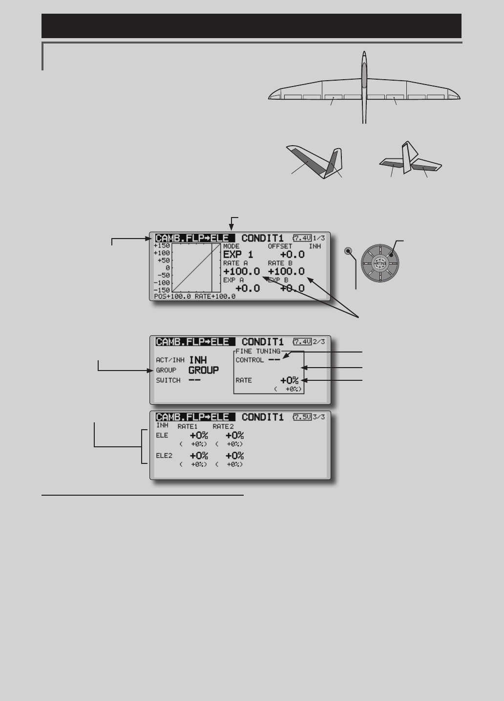
ELE to CAMBER [Correspondingmodeltype]:Airplane/glider,2aileronsormore
This function is used when you want to mix the
camber aps with elevator operation. When used,
the aps are lowered by up elevator, and lift can
be increased.
Note: Tailless wing elevator can be operated
when this mix is activated.
●Amixingcurvecanbeset.
●MixingduringightcanbeturnedON/OFFby
settingaswitch.(AlwaysONat[--]setting)
●Themixingratecanbene-tunedbysettingaVR.
●Aileronsandapsrateadjustment
1. Selecttherateboxandpushthe
RTNbuttontoswitchtothedata
inputmode.
2. Adjusttheratesby scrolling the
editdial.
3. PushtheRTN button to end
adjustmentandreturntothe
cursormovemode.
Setting method
●MovethecursortotheACT/INHitemand
pushtheRTNbuttontoswitchtothedata
inputmode.
TurntheeditdialtotheleftandpushtheRTN
button.(ONisdisplayed.)
●Whensettingaswitch,movethecursorto
the[--]itemoftheswitchandpushtheRTN
buttontocalltheselectionscreen,andthen
selecttheswitchandsetitsONdirection.
(AlwaysONat"--"setting)
(Foradescriptionoftheswitchselection
method,seethedescriptionatthebackof
thismanual.)
●WhensettingaVR,movethecursortothe
Finetuning"--"itemandpushtheRTNbutton
tocalltheselectionscreen,andthenselect
theVR.Theadjustmentratecanbeset.
TheVRoperationmodecanalsobe
selected.
●Amixingcurvecanalsobeset.
(Foradescriptionofthecurvesetting
method,seethedescriptionatthebackof
thismanual.)
●Group/singlemode
switching
(For more information, refer
to the description at the
back of this manual.)
●OveralladjustmentbyRate
AandRateB.
(Currently selected condition name)
●Select[ELEtoCAMBER]atthemodelmenuand
callthesetupscreenshownbelowbypushingthe
RTNbutton.
●Mixingcurvesetting
*For a description of the
curve setting method, see
the description at the back
of this manual.
*The display screen is an example.
The actual screen depends on the
model type.
●FinetuningVRsetting
●Adjustmentrate
●Operationmode
Scrolling
●Movingcursor
●Selectingmode
●Adjustingvalue
●PushtheS1button
tocallnextpage.
131
<Model Menu (Airplane/Glider Functions) >
Reference FMT-03 is equipped with a stick of multi-copter exclusive use. Therefore it's
unsuitable for use of an airplane, a glider and a helicopter.
S1
●Selectthefunction
nameandreturntothe
precedingscreenby
pushingtheRTNbutton
orpushingtheHome/Exit
button.
<Editdial>
ELEVATOR ELEVATOR 2
V-TAIL
ELEVATOR ELEVATOR 2
AILVATOR
FLP 2
(Camber Flap)
FLP 1
(Camber Flap)
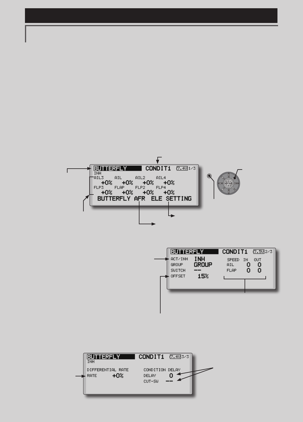
CAMB.FLP to ELE [Correspondingmodeltype]:Airplane/
glider, 2ailerons+1apormore
This mixing is used to correct changes (elevator
direction) generated when the camber aps (speed
aps) are used.
●Theelevatorservosupside/downsideratecanbe
adjusted.Whenthemixingdirectionisreversed
bythelinkage,adjustmentscanbemadeby
changingthemixingratepolarity(+or–).
●Amixingcurvecanbeset.
●MixingduringightcanbeturnedON/OFFby
settingaswitch.(AlwaysONat[--]setting)
●Themixingratecanbene-tunedbysettingaVR.
●Elevatorrateadjustment
Setting method
●MovethecursortotheACT/INHitemand
pushtheRTNbuttontoswitchtothedata
inputmode.
TurntheeditdialtotheleftandpushtheRTN
button.(ONisdisplayed.)
●Whensettingaswitch,movethecursorto
the[--]itemoftheswitchandpushtheRTN
buttontocalltheselectionscreen,andthen
selecttheswitchandsetitsONdirection.
(AlwaysONat"--"setting)
(Foradescriptionoftheswitchselection
method,seethedescriptionatthebackof
thismanual.
●Movethecursortotheelevatorservosleft
andrightitemandpushtheRTNbutton to
switchtothedatainputmode.Adjustthe
mixingratewiththeeditdial.
PushtheRTNbuttontoendadjustmentand
returntothecursormovemode.
*When the mixing direction is reversed by the linkage,
adjustments can be made by changing the mixing rate
polarity (+ or –).
●WhensettingaVR,movethecursortothe
Finetuning"--"itemandpushtheRTNbutton
tocalltheselectionscreen,andthenselect
theVR.TheVRoperationmodecanbe
selected.
●Amixingcurvecanbeset.
(Foradescriptionofthecurvesetting
method,seethedescriptionatthebackof
thismanual.)
●Overalladjustmentby
RateAandRateB.
(Currently selected condition name)
●Select[CAMB.FLPtoELE]atthemodelmenuand
callthesetupscreenshownbelowbypushingthe
RTNbutton.
●Mixingcurvesetting
*For a description of the curve setting method, see the
description at the back of this manual.
*The display screen is an example.
The actual screen depends on the
model type.
●FinetuningVRsetting
●Adjustmentrate
●Operationmode
●Group/singlemode
switching
(For more information, refer
to the description at the back
of this manual.)
Scrolling
●Movingcursor
●Selectingmode
●Adjustingvalue
●PushtheS1button
tocallnextpage.
132 <Model Menu (Airplane/Glider Functions) >
Reference FMT-03 is equipped with a stick of multi-copter exclusive use. Therefore it's
unsuitable for use of an airplane, a glider and a helicopter.
S1
●Selectthefunction
nameandreturntothe
precedingscreenby
pushingtheRTNbutton
orpushingtheHome/Exit
button.
<Editdial>
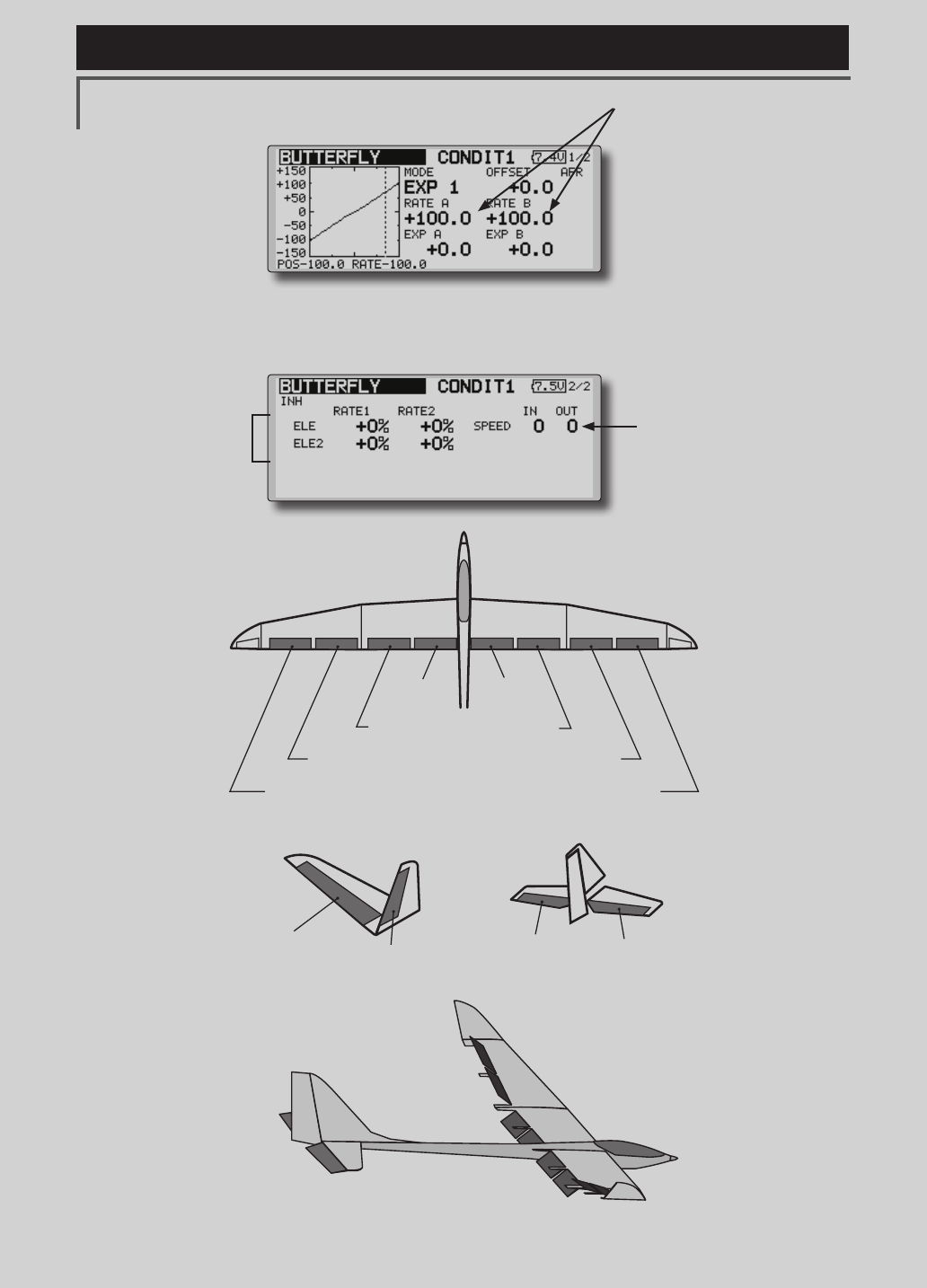
BUTTERFLY [Correspondingmodeltype]:Glider,2aileronsormore
This function allows powerful brake operation
by simultaneously raising the left and right
ailerons and lowering the flaps (camber flap,
brake ap).
This setting will allow the ailerons to be raised
while the flaps are simultaneously lowered.
Butterfly (crow) produces an extremely efficient
landing configuration by accomplishing the
following:
1.Slowtheaircraft’svelocity.
2.Providewashoutatthewingtipstoreduce
thetendencytotipstall.
3.Createmorelifttowardthecenterofthe
wingallowingittoyataslowerspeed
●MixingduringightcanbeturnedON/OFFby
settingaswitch.(AlwaysONat[--]setting)
●Thebutteryoperationreferencepointcan
beoffset.WhentheRTNbuttonispushedwith
theoffsetitemselectedwhenoperatedtothe
positiontobechanged,thereferencepointis
offset.Ifthereferencepointisoffsettoomuch,
unexpectedoperationmaybeperformed.
●Theaileronsandapsoperationspeedcanbe
adjusted.(INside/OUTside)
●Adelaycanbesetforeachcondition.Acut
switchwhichcanturnOFFthedelayfunctioncan
alsobeset.
●Thedifferentialratecanbeadjusted.
*When servo binding occurs when setting the ailerons and
aps in buttery mixing, use the AFR function to adjust the
rudder angle.
●Whenoffsettingthebutterflyoperationreferencepoint,
operatetothepointyouwanttochangeandthenpress
theEDITbuttonfor1second."INITIALIZEELEVATORCURVE?"
isdisplayed.PleasechoosewhethertoinitializebyYES,or
nottoinitializebyNO.
●Differentialrate
adjustment
●Toelevatorcorrectionsetupscreen
●CallstheButteryAFR(D/R)setupscreen
(For a description of the setting method, see the description at the
back of this manual.)
●Aileronandapservosspeedsetting
(For a description of the setting method, see the
description at the back of this manual.)
●Conditiondelaysettingand
cutswitchsetting
(For a description of the setting
method, see the description at the
back of this manual.)
● SelecttheMixingRateAILandFLP box and
pushtheRTNbuttontoswitchtothedatainput
mode.Adjustthemixingrates.
PushtheRTNbuttontoendadjustmentand
returntothecursormovemode.
(Currently selected condition name)
●Select[BUTTERFLY]atthemodelmenuand call
thesetupscreenshownbelowbypushingtheRTN
button.
*The display screen is an example. The actual
screen depends on the model type.
●Whenusingthisfunction,movethecursortothe[ACT/
INH]itemandpushtheRTNbuttontoswitchtothe data
inputmode.TurntheeditdialtotheleftandpushtheRTN
button.(ONisdisplayed.)
●Group/singlemodeswitching
(For more information, see the description at the back of this
manual.)
●Whensettingaswitch,selecttheSWITCH[--]boxandpush
theRTNbuttontoswitchtothedatainputmode.Pressthe
EDITbuttontocalltheselectionscreen,andthenselectthe
switchandsetitsONdirection.
Scrolling
●Movingcursor
●Adjustingvalue
●PushtheS1button
tocallnextpage.
133
<Model Menu (Airplane/Glider Functions) >
Reference FMT-03 is equipped with a stick of multi-copter exclusive use. Therefore it's
unsuitable for use of an airplane, a glider and a helicopter.
AIL 3
(Chip Aileron) AIL 4
(Chip Aileron)
AIL1
(Main Aileron) AIL 2
(Main Aileron)
FLP 2
(Camber Flap)
FLP 1
(Camber Flap)
ELEVATOR ELEVATOR 2
V-TAIL
ELEVATOR ELEVATOR 2
AILVATOR
FLP 3
(Brake Flap) FLP 4
(Brake Flap)
(Elevatorcorrectionratesetupscreen)
●Servospeedsetting
(For a description of the setting
method, see the description at the
back of this manual.)
●OveralladjustmentbyRateA
andRateB
●Elevatorrate
adjustment
●Mixingcurvesetting
*For a description of the curve setting method, see the
description at the back of this manual.
134 <Model Menu (Airplane/Glider Functions) >
Reference FMT-03 is equipped with a stick of multi-copter exclusive use. Therefore it's
unsuitable for use of an airplane, a glider and a helicopter.
S1
●Selectthefunction
nameandreturntothe
precedingscreenby
pushingtheRTNbutton
orpushingtheHome/Exit
button.
<Editdial>
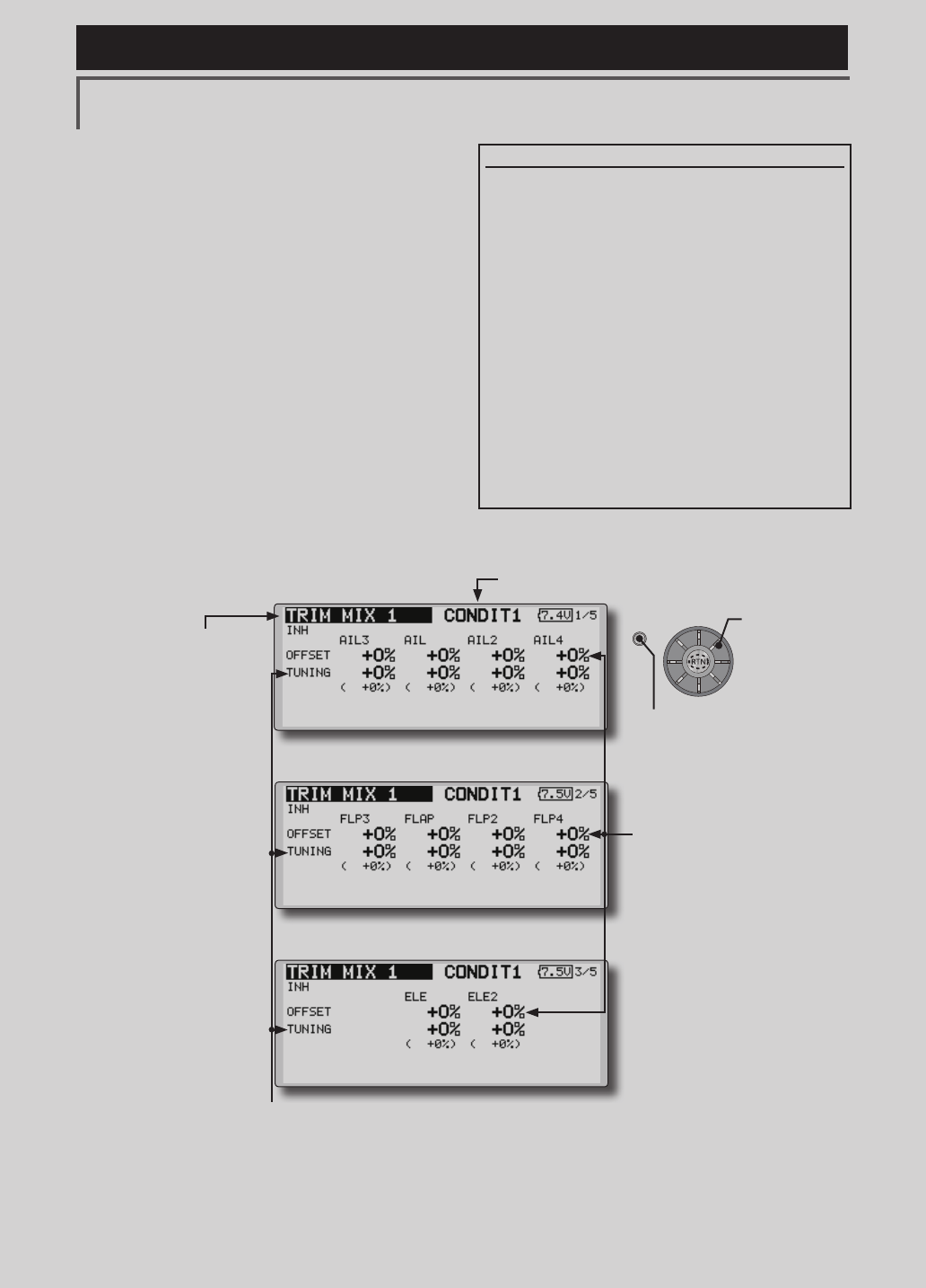
TRIM MIX 1/2 [Correspondingmodeltype]:Glider,2aileronsormore
These functions call the ailerons, elevators, and
aps (camber aps, brake aps) trim offset rates
preset according to the ight state.
The amount of ailerons, elevator, and flaps
(camber ap, brake ap) trim offset can be set to
a switch.
As an example Trim Mix 1 can be set up for
launching, with speed aps and ailerons dropped,
and a slight amount of up elevator. Trim mix
2 can be used for high speed flying, with both
ailerons and speed aps reexed slightly, and a bit
of down elevator.
The trim functions can be activated during
ight by setting a switch. To prevent sudden trim
changes when switching ight conditions, a delay
can be set to provide a smooth transition between
the two. Trim Mix 2 will have priority over Trim
Mix 1.
●WhenanetuningVRissetonthenextpage,theaileronsapsandelevators
trimratescanbeadjusted.
MovethecursortothecorrespondingsettingitemandpushtheRTNbuttonto
switchtothedatainputmode.adjusttheratewiththeeditdial.
PushtheRTNbuttontoendadjustmentandreturntothecursormovemode.
●Theailerons,aps,andelevators
offsetratecanbeadjusted.
Movethecursortothe
correspondingsettingitemand
pushtheRTNbuttontoswitchto
thedatainputmode.Adjustthe
ratewiththeeditdial.
PushtheRTNbuttontoend
adjustmentandreturntothe
cursormovemode.
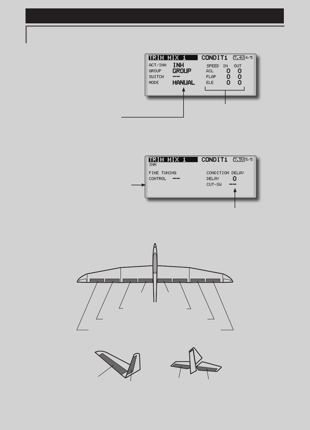
Example
1.MovetotheACT/INHitemandpushtheRTN
buttontoswitchtothedatainputmode.Setthe
trimmixfunctionto[ON].
*When separating the settings for each condition, move to
the [GROUP] item and set it to [Single].
2.SelecttheON/OFFswitch.
3.Selectthe[Manual]or[Auto]mode.
Inthe[Auto] mode,alsoselectanautoSW.This
switchcanbelinkedtoastick,etc.
<Speed>
In:TheoperationspeedatswitchONcanbeset.
Out:ThereturnspeedatswitchOFFcanbeset.
<FineTuning>
TheoffsetratecanbevariedintheFineTuning
numericrangesetatscreen[5/5]by VR,etc.
selection.
<ConditionDelay>
Whenightconditionsareset,theoperationspeed
canbesetforeachcondition.Conditiondelay
operationcanbeinterruptedandeachrudder
quicklyreturnedtoitsoriginalpositionbyselectinga
cutswitch.
(Currently selected condition name)
●Select[TRIMMIX1or2]atthemodelmenuandcall
thesetupscreenshownbelowbypushingtheRTN
button.
*The display screen is an example. The actual screen depends
on the model type.
Scrolling
●Movingcursor
●Adjustingvalue
●PushtheS1button
tocallnextpage.
135
<Model Menu (Airplane/Glider Functions) >
Reference FMT-03 is equipped with a stick of multi-copter exclusive use. Therefore it's
unsuitable for use of an airplane, a glider and a helicopter.
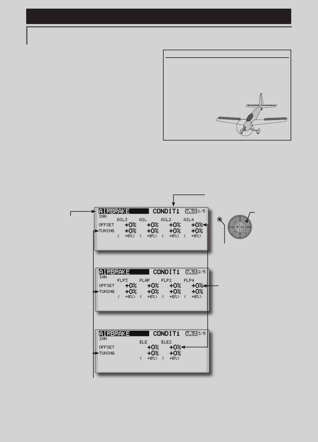
●Whenusingthisfunction,movethecursortothe[ACT/
INH]itemandpushtheRTNbuttontoswitchtothe
datainputmode.Turntheeditdialtotheleftand
pushtheRTNbutton.(ONisdisplayed.)
●Group/singlemodeswitching
(For more information, see the description at the back of this
manual.)
●WhenusingafinetuningVR,movethecursor
tothisitemandpushtheRTNbuttontocallthe
selectionscreen.
SelecttheVRandpushtheRTNbutton.
●Conditiondelaysetting(foradescriptionofthe
settingmethod,seethedescriptionattheback
ofthismanual)andcutswitchsetting.
●Ailerons,flaps,anelevatorsservospeed
setting
(For a description of the setting method, see the
description at the back of this manual.)
●Manual/Automodeselection
Manual:SwitchesthefunctionON/OFFbyswitch
Auto:Trimmixfunctioncallcanbelinkedtoastick,etc.A
stickswitch,etc.separatefromthefunctionON/OFFswitch
isset.
AIL 3
(Chip Aileron) AIL 4
(Chip Aileron)
AIL1
(Main Aileron) AIL 2
(Main Aileron)
FLP 2
(Camber Flap)
FLP 1
(Camber Flap)
ELEVATOR ELEVATOR 2
V-TAIL
ELEVATOR ELEVATOR 2
AILVATOR
FLP 3
(Brake Flap) FLP 4
(Brake Flap)
136 <Model Menu (Airplane/Glider Functions) >
Reference FMT-03 is equipped with a stick of multi-copter exclusive use. Therefore it's
unsuitable for use of an airplane, a glider and a helicopter.
S1
●Selectthefunction
nameandreturntothe
precedingscreenby
pushingtheRTNbutton
orpushingtheHome/Exit
button.
<Editdial>
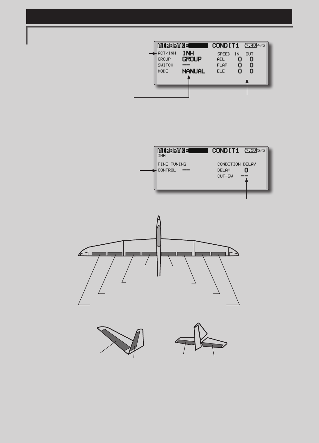
AIRBRAKE [Correspondingmodeltype]:Airplane,general
This function is used when an air brake is
necessary when landing or diving, etc.
The preset elevators and flaps (camber flap,
brake flap) offset amount can be activated by a
switch.
The offset amount of the aileron, elevator, and
flap servos can be adjusted as needed. Also the
speed of the aileron, elevator, and ap servos can
be adjusted. (IN side/OUT side) A delay can be set
for each condition, and a Cut switch which will
turn OFF the delay can be chosen. Trim amounts
can be fine-tuned by setting a VR You can also
set the Auto Mode, which will link Airbrake to a
stick, switch, or dial. A separate stick switch or
dial can also be set as the ON/OFF switch.
Setting example for F3A and other aperon specications
(When2aileronsmodeltypeselected)
Offsetrate:
AIL:[-35~-45%],AIL2:[-35~-45%],ELE:[+5~7%]
Note: The input numerics are examples. Adjust the travel to
match the aircraft.
Modesetting:
ACT:[ON]
Group:[Single]
Switch:[SW-C]
Mode:[Manual]
●WhenanetuningVRissetonthenextpage,theailerons',aps',andelevators'
trimratescanbeadjusted.
MovethecursortothecorrespondingsettingitemandpushtheRTNbuttonto
switchtothedatainputmode.Adjusttheratewiththeeditdial.
PushtheRTNbuttontoendadjustmentandreturntothecursormovemode.
●Theailerons,aps,andelevators
offsetratecanbeadjusted.
Movethecursortothe
correspondingsettingitemand
pushtheRTNbuttontoswitchto
thedatainputmode.Adjustthe
ratewiththeeditdial.
PushtheRTNbuttontoend
adjustmentandreturntothe
cursormovemode.
(Currently selected condition name)
●Select[AIRBRAKE]atthemodelmenuandcallthesetupscreen
shownbelowbypushingtheRTNbutton.
*The display screen is an example. The actual
screen depends on the model type.
Scrolling
●Movingcursor
●Adjustingvalue
●PushtheS1button
tocallnextpage.
137
<Model Menu (Airplane/Glider Functions) >
Reference FMT-03 is equipped with a stick of multi-copter exclusive use. Therefore it's
unsuitable for use of an airplane, a glider and a helicopter.
●Whenusingthisfunction,movethecursortothe[ACT/
INH]itemandturntheeditdialtotheleftandpush
theRTNbutton.(ONisdisplayed.)
●Group/singlemodeswitching
(For more information, see the description at the back of this
manual.)
●WhenusingafinetuningVR,move the
cursortothissettingitemandpressthe
EDITbuttontocalltheselectionscreen.
SelecttheVRandpushtheRTNbutton.
●Conditiondelaysetting(foradescriptionofthe
settingmethod,seethedescriptionattheback
ofthismanual)andcutswitchsetting.
●Ailerons,flaps,anelevatorsservospeed
setting
(For a description of the setting method, see the
description at the back of this manual.)
●Manual/Automodeselection
Manual:SwitchesthefunctionON/OFFbyswitch
Auto:Trimmixfunctioncallcanbelinkedtoastick,etc.A
stickswitch,etc.separatefromthefunctionON/OFFswitch
isset.
AIL 3
(Chip Aileron) AIL 4
(Chip Aileron)
AIL1
(Main Aileron) AIL 2
(Main Aileron)
FLP 2
(Camber Flap)
FLP 1
(Camber Flap)
ELEVATOR ELEVATOR 2
V-TAIL
ELEVATOR ELEVATOR 2
AILVATOR
FLP 3
(Brake Flap) FLP 4
(Brake Flap)
138 <Model Menu (Airplane/Glider Functions) >
Reference FMT-03 is equipped with a stick of multi-copter exclusive use. Therefore it's
unsuitable for use of an airplane, a glider and a helicopter.
S1
●Selectthefunction
nameandreturntothe
precedingscreenby
pushingtheRTNbutton
orpushingtheHome/Exit
button.
<Editdial>
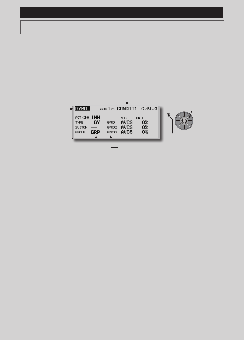
GYRO [Correspondingmodeltype]:Airplane/glider,general
This function is used when a GYA Series gyro
is used to stabilize the aircraft's attitude. The
sensitivity and operation mode (Normal mode/GY
mode) can be switched with a switch.
●Threerates(Rate1/Rate2/Rate3)canbe
switched.
●Upto3axes(Gyro/Gyro2/Gyro3)canbe
simultaneouslycontrolled.
*Initial setting does not assign a sensitivity channel. Use the
Function menu of the Linkage Menu to assign the sensitivity
channel (Gyro/Gyro2/Gyro3) used to a vacant channel
beforehand.
Set [Control] and [Trim] other than Function to [--].
●Theoperationmode(AVCS/NOR)andsensitivityofthe3axis
controlledbyGyro/Gyro2/Gyro3canbeset.
●Group/singlemodeswitching
(For more information, see the
description at the back of this
manual.)
●Threerates(Rate1/Rate2/Rate3)canbeused.
Movethecursortothe[RATE]itemandpushtheRTNbuttontoswitchto
thedatainputmode.Adjusttheratebyscrollingtheeditdial.
●Whenusingthisfunction,movethecursortothe[ACT]itemandpush
theRTNbuttontoswitchtothedatainputmode.Turntheeditdialto
theleftandpushtheRTNbutton.
●WhenaFutabaGYAgyroisused,when[GY]typeisselected,the
sensitivitysetvalueisdirectlyreadinboththeAVCSandNORMmodes.
●Whensettingaswitch,movethecursortotheSWITCHitemandpress
theEDITbuttontocalltheselectionscreen,andthenselecttheswitch
andsetitsONdirection.
(Foradescriptionoftheswitchselectionmethod,seethedescriptionat
theendofthismanual.)
(Currently selected condition name)
●Select[GYRO]atthemodelmenuandcallthe
setupscreenshownbelowbypushingthe RTN
button.
Scrolling
●Movingcursor
●Selectingmode
●Adjustingvalue
●PushtheS1button
tocallnextpage.
139
<Model Menu (Airplane/Glider Functions) >
Reference FMT-03 is equipped with a stick of multi-copter exclusive use. Therefore it's
unsuitable for use of an airplane, a glider and a helicopter.
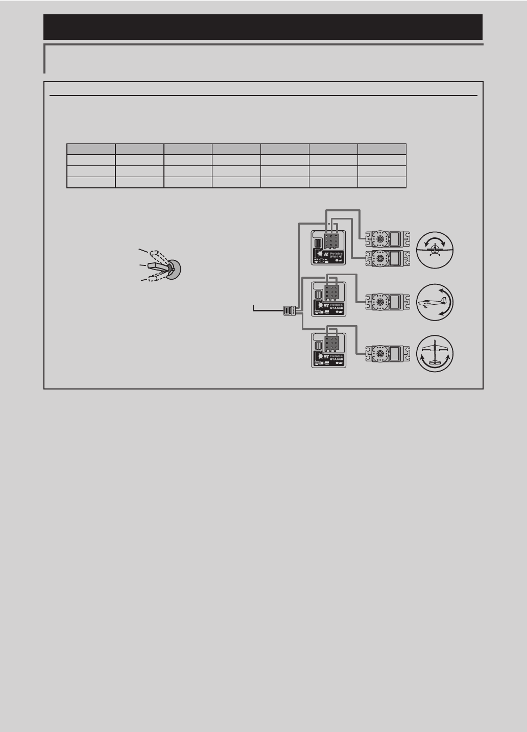
(Example) Setting three axis using a GYA440(2) and GYA441
●Wingtype:Aileron2servosmountedfuselageselected
●Set5CH → GYRO(GYA441AIL),7CH → GYRO2(GYA441ELE),8CH → GYRO3(GYA440RUD),Control and Trim → NULL :
attheFunctionmenuoftheLinkagemenu.
●GYROsettingoftheModelmenu.
*Set so that Rate 1 is turned on at the back position of switch E
and Rate 3 is turned ON at the front position. Since switch E is
turned OFF at the center, Rate 2 remains [INH].
Rudder servo
Elevator servo
Aileron servo
FMR-01
GYA440
GYA441
GYA440
GAIN 0%
AVCS
NORMAL
When AVCS is used we
recommend that the
sensitivity CH be set to
the 3-position.
Rate ACT Type Switch GYRO GYRO 2 GYRO 3
1 OFF/ON GY SE AVCS : 60% AVCS : 60% AVCS : 60%
2 INH
3 ON/OFF GY SE NORM : 60% NORM : 60% NORM : 60%
140 <Model Menu (Airplane/Glider Functions) >
Reference FMT-03 is equipped with a stick of multi-copter exclusive use. Therefore it's
unsuitable for use of an airplane, a glider and a helicopter.
S1
●Selectthefunction
nameandreturntothe
precedingscreenby
pushingtheRTNbutton
orpushingtheHome/Exit
button.
<Editdial>
ELEVATOR
(RUDDER 2) RUDDER
(ELEVATOR 2)
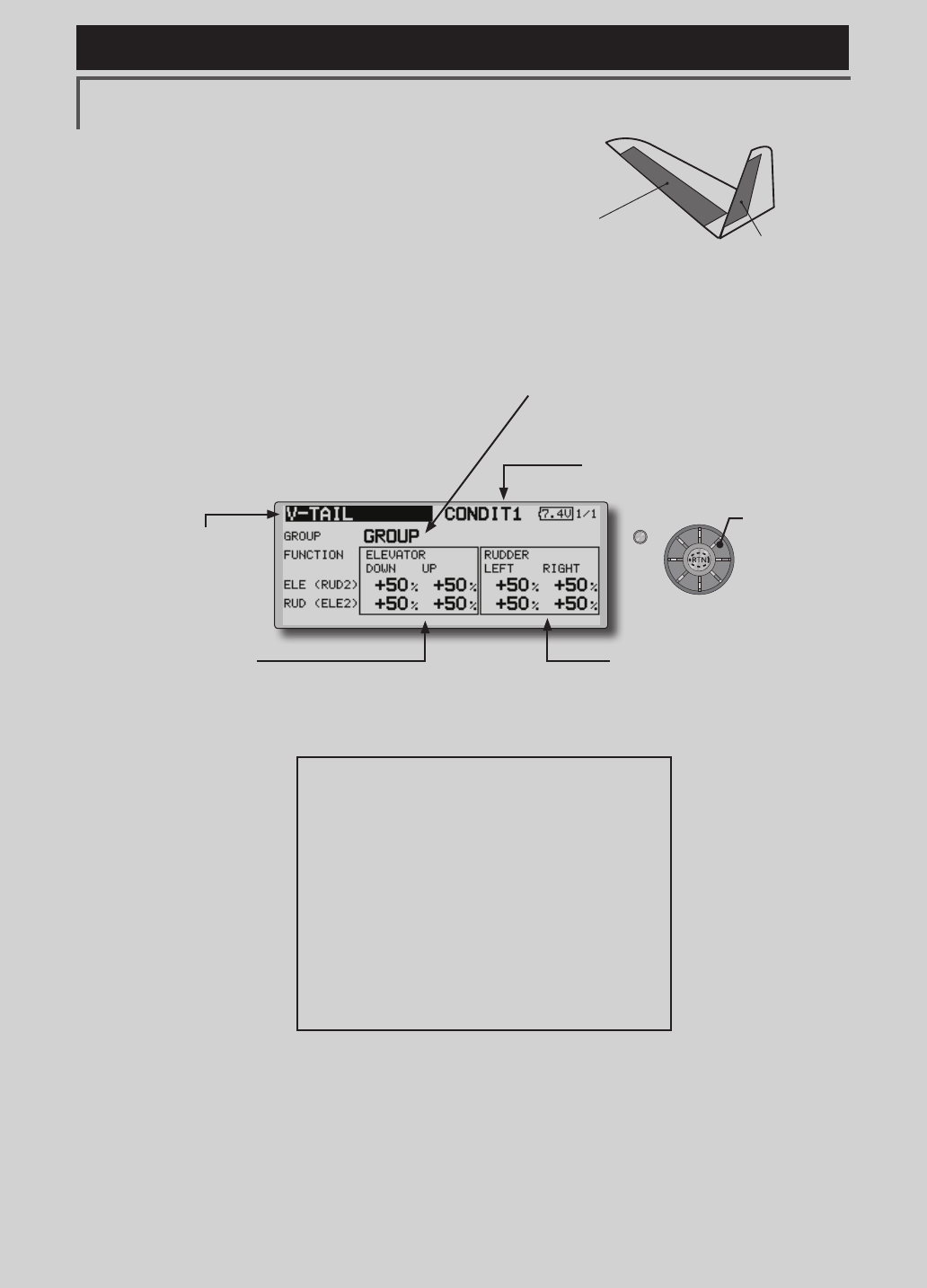
V-TAIL [Correspondingmodeltype]:Airplane/glider,V-tail
This function let’s you adjust for left and right
rudder angle changes at elevator and rudder
operation of a V-tail airplane.
V-tail is when 2 servos are used together to
control rudder movement as elevators. In addition
to each rudder side moving up and down together,
each side moves in opposite directions when moving
as elevators. On a V-tail, this is also known as a
ruddervator, as they can serve the same purpose.
(Rudderfunction)
Leftandrighttraveladjustmentat
CH1andCH2rudderoperation
●Group/singlemodeswitching
(For more information, see the description at the
back of this manual.)
(Elevatorfunction)
Upanddowntraveladjustmentat
CH1andCH2elevatoroperation
(Currently selected condition name)
●Select[V-TAIL]atthemodelmenuand
callthesetupscreenshownbelowby
pushingtheRTNbutton.
●Traveladjustment
Movethecursortotheitemyouwantto
adjustandpushtheRTNbuttontoswitchto
thedatainputmode.
Adjusttheratebyscrollingtheeditdial.
PushtheRTNbuttontoendadjustmentand
returntothecursormovemode.
*If the mixing direction is reversed by the linkage,
adjustments can be made by changing the mixing rate
polarity (+ or -).
*If a large value of travel is specied, when the sticks are
moved at the same time, the controls may bind or run out
of travel. Decrease the travel until no binding occurs.
Scrolling
●Movingcursor
●Selectingmode
●Adjustingvalue
141
<Model Menu (Airplane/Glider Functions) >
Reference FMT-03 is equipped with a stick of multi-copter exclusive use. Therefore it's
unsuitable for use of an airplane, a glider and a helicopter.
S1
●Selectthefunction
nameandreturntothe
precedingscreenby
pushingtheRTNbutton
orpushingtheHome/Exit
button.
<Editdial>
ELEVATOR ELEVATOR 2
(AILERON 5) (AILERON 6)
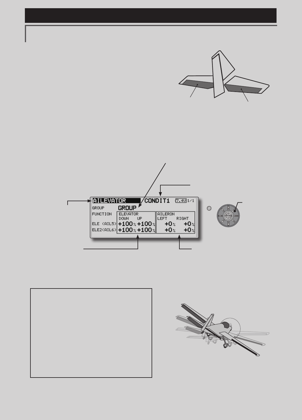
AILEVATOR [Correspondingmodeltype]:Airplane/glider,V-Tail
(Effective only when 2 servos used at the elevators)
This function improves the operating
performance of the roll axis by operating the
elevators as ailerons.
Ailevator is where each elevator in a standard
(conventional) or v-tail moves independently, like
ailerons on a wing. In addition to each elevator side
moving up and down together, each side moves in
opposite directions when moving as an ailevator.
On a V-tail, this is also known as a ruddervator,
as they can serve the same purpose. Typically,
both ailevator and ailerons are coupled together to
maximize roll performance, especially on larger
wingspan planes.
Note:SelectailevatorastheModeltypeatthe
Modeltypescreen.Thischangestheoutput
channel.ChecktheFunctionmenu.
(Aileronfunction)
●Whentheelevatorsareusedas
ailerons,ailerontraveloftheleftand
rightelevatorscanbeadjusted.
(Elevatorfunction)
●Theupanddownrateoftheleftand
rightelevatorswhentheelevatorstickis
manipulatedcanbeindividuallyadjusted.
●Group/singlemodeswitching
(For more information, see the description at the
back of this manual.)
(Currently selected condition name)
●Select[AILEVATOR]atthemodelmenu
andcallthesetupscreenshownbelow
bypushingtheRTNbutton.
●Traveladjustment
Movethecursortotheitemyouwantto
adjustandpushtheRTNbuttontoswitchto
thedatainputmode.
Adjusttheratebyscrollingtheeditdial.
PushtheRTNbuttontoendadjustmentand
returntothecursormovemode.
*If the mixing direction is reversed by the linkage,
adjustments can be made by changing the mixing rate
polarity (+ or -).
*If a large value of travel is specied, when the sticks are
moved at the same time, the controls may bind or run out
of travel. Decrease the travel until no binding occurs.
Scrolling
●Movingcursor
●Selectingmode
●Adjustingvalue
142 <Model Menu (Airplane/Glider Functions) >
Reference FMT-03 is equipped with a stick of multi-copter exclusive use. Therefore it's
unsuitable for use of an airplane, a glider and a helicopter.
S1
●Selectthefunction
nameandreturntothe
precedingscreenby
pushingtheRTNbutton
orpushingtheHome/Exit
button.
<Editdial>
RUDDER 1
Winglet
at Flying wing
( )
RUDDER 2
Winglet
at Flying wing
( )
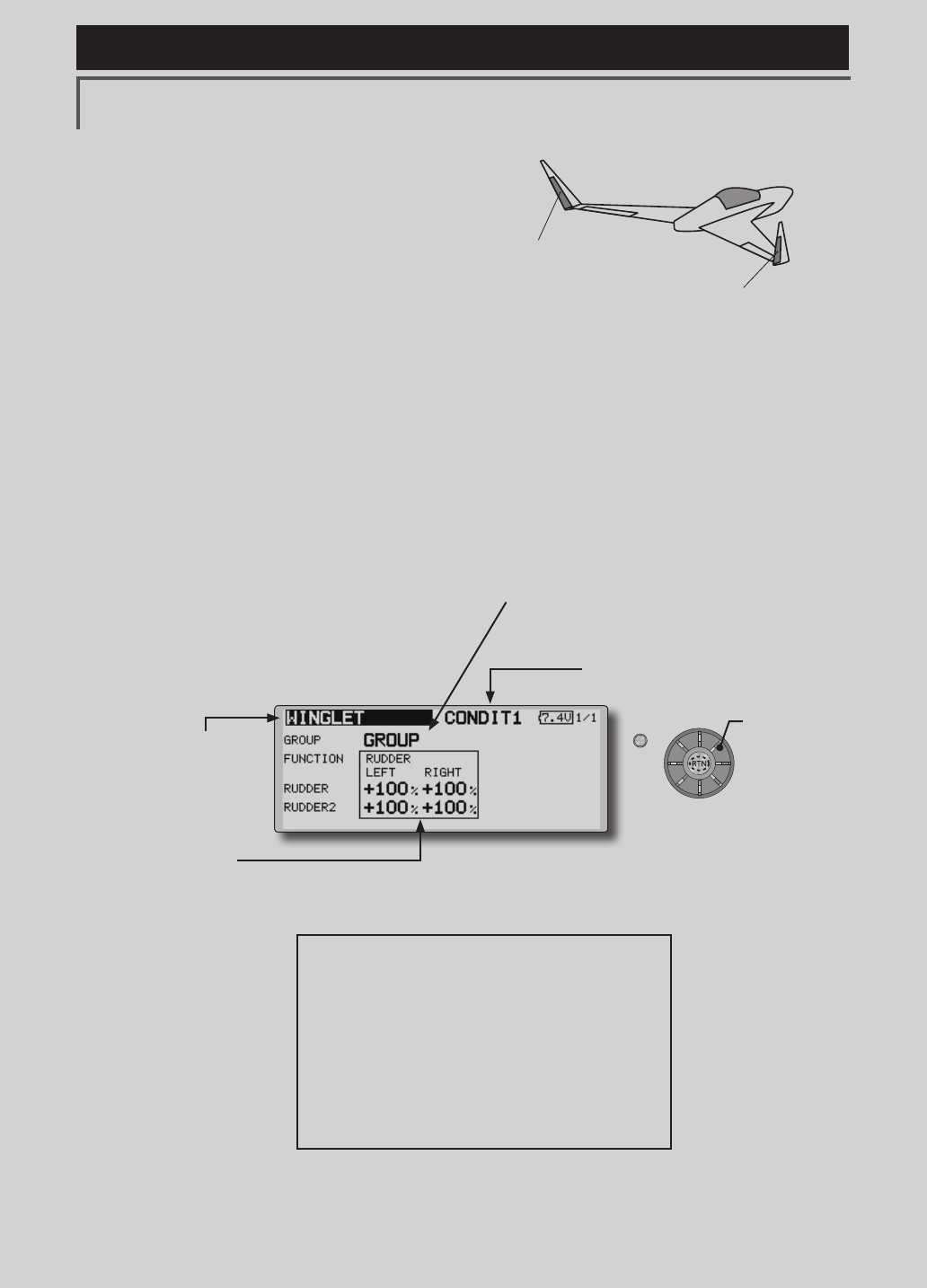
WINGLET [Correspondingmodeltype]:Airplane/glider,winglet
This function adjusts the left and right rudder
angles of airplanes with winglets.
Winglets are used to improve the efficiency of
aircraft lowering the lift-induced drag caused by
wingtip vortices. The winglet is a vertical or angled
extension at the tips of each wing.
Winglets work by increasing the effective aspect
ratio wing without adding greatly to the structural
stress and hence necessary weight of its structure
- an extension of wing span would also permit
lowering of induced drag, though it would cause
parasitic drag and would require boosting the
strength of the wing and hence its weight - there
would come a point at which no overall useful
saving would be made. A winglet helps to solve this
by effectively increasing the aspect ratio without
adding to the span of the wing.
(Rudder1/2)
●Thetravelatrudderstickleftandright
operationcanbeindividuallyset.
●Group/singlemodeswitching
(For more information, see the description at the
back of this manual.)
(Currently selected condition name)
●Select[WINGLET]atthemodelmenuand
callthesetupscreenshownbelowby
pushingtheRTNbutton.
●Traveladjustment
Movethecursortotheitemyouwantto
adjustandpushtheRTNbuttontoswitchto
thedatainputmode.
Adjusttheratebyscrollingtheeditdial.
PushtheRTNbuttontoendadjustmentand
returntothecursormovemode.
*If the mixing direction is reversed by the linkage,
adjustments can be made by changing the mixing rate
polarity (+ or -).
Scrolling
●Movingcursor
●Selectingmode
●Adjustingvalue
143
<Model Menu (Airplane/Glider Functions) >
Reference FMT-03 is equipped with a stick of multi-copter exclusive use. Therefore it's
unsuitable for use of an airplane, a glider and a helicopter.
S1
●Selectthefunction
nameandreturntothe
precedingscreenby
pushingtheRTNbutton
orpushingtheHome/Exit
button.
<Editdial>
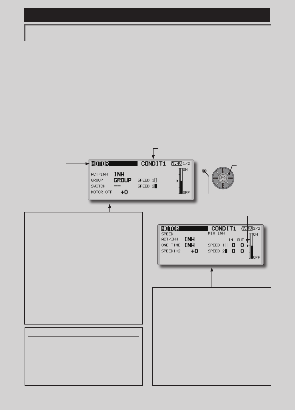
MOTOR [Correspondingmodeltype]:EPglider,general
This function lets you set the operation speed
when the motor of a F5B or other EP glider is
started by switch. The operation speed can be set
in 2 ranges of slow speed flight and high speed
ight (Speed 1/Speed 2). This function can also be
operated as a safety function by setting 2 switches.
●Theinsideandoutsideoperatingspeedscanbe
adjustedindependentlyin2ranges(Speed1/
Speed2).
●Theboundarybetweenthe2rangescanbeset.
(Fromspeed1tospeed2)
●Thesetoperationspeedoperationcanbe
activatedatinitialoperationonly.(1time
operation)However,operationcanberepeated
●Movethecursorbyset
switchorVR.
bysettingtheswitchtoOFFbeforeoperationis
nished.Whenyouwanttoreset1timeoperation,
settheACT/INHitemto[INH]andthenresetitto
[ON].
●Themotor(CH3)iscontrolledbySW-G.(Initial
setting)Whenchangingtheswitchorstickwhich
controlsthemotor,rstchangeFunctionofthe
LinkageMenu.
Note: When using this function, always check initial
operation with the propeller removed.
●Whenusingthisfunction,movethecursor
tothe[ACT/INH]itemandpushtheRTN
buttontoswitchtothedatainputmode.
Turntheeditdialtothe leftandpushthe
RTNbutton.
●Whenyouwanttosetthe"Onetimemode",
movethecursortothe[ONETIME]itemand
turntheeditdialtotheleftandpushthe
RTNbutton.
●Speed1to2
Thespeed1andspeed2regionboundary
canbechanged,
●Operationspeedadjustment
Thespeedwhenspeed1andspeed2are
ON(In)andOFF(Out)canbeadjusted.
●Whenusingthisfunction,movethecursor
tothe[ACT/INH]itemandpushtheRTN
buttontoswitchtothedatainputmode.
Turntheeditdialtotheleftandpushthe
RTNbutton.
●Group/singlemodeswitching
(Formoreinformation,seethedescription
atthebackofthismanual.)
●Switch
Aswitchthatturnsthefunctionitself
ON/OFFcanbeselected.
●Motoroffposition
PresstheEDITbuttonfor1secondwhen
[SW-G]isinthemotorOFFpositionyouwant
toset.Thedirectionofthemotorswitchis
memorized.ThescreengraphdisplayOFF
directionalsochanges.
Notes
●FirstdecidethemotorOFFdirection,andthen
setthespeed.Whenyouwanttoresetthe
motorOFFdirection,alsoresetthespeed.
●WerecommendthatmotorOFFbesetin
combinationwithF/S.
●Setthebasicoperationdirectionwiththereverse
functiontomatchtheESCused.
●AlwayssetthemotorOFFposition.
(Currently selected condition name)
●Select[MOTOR]atthemodelmenuandcallthe
setupscreenshownbelowbypushingthe RTN
button.
Scrolling
●Movingcursor
●Selectingmode
●Adjustingvalue
●PushtheS1button
tocallnextpage.
144 <Model Menu (Airplane/Glider Functions) >
Reference FMT-03 is equipped with a stick of multi-copter exclusive use. Therefore it's
unsuitable for use of an airplane, a glider and a helicopter.
S1
●Selectthefunction
nameandreturntothe
precedingscreenby
pushingtheRTNbutton
orpushingtheHome/Exit
button.
<Editdial>
[Correspondingmodeltype]:Glider,general
CONDIT1
1/3
ELEVATOR
-50 +50
ACCELERATION
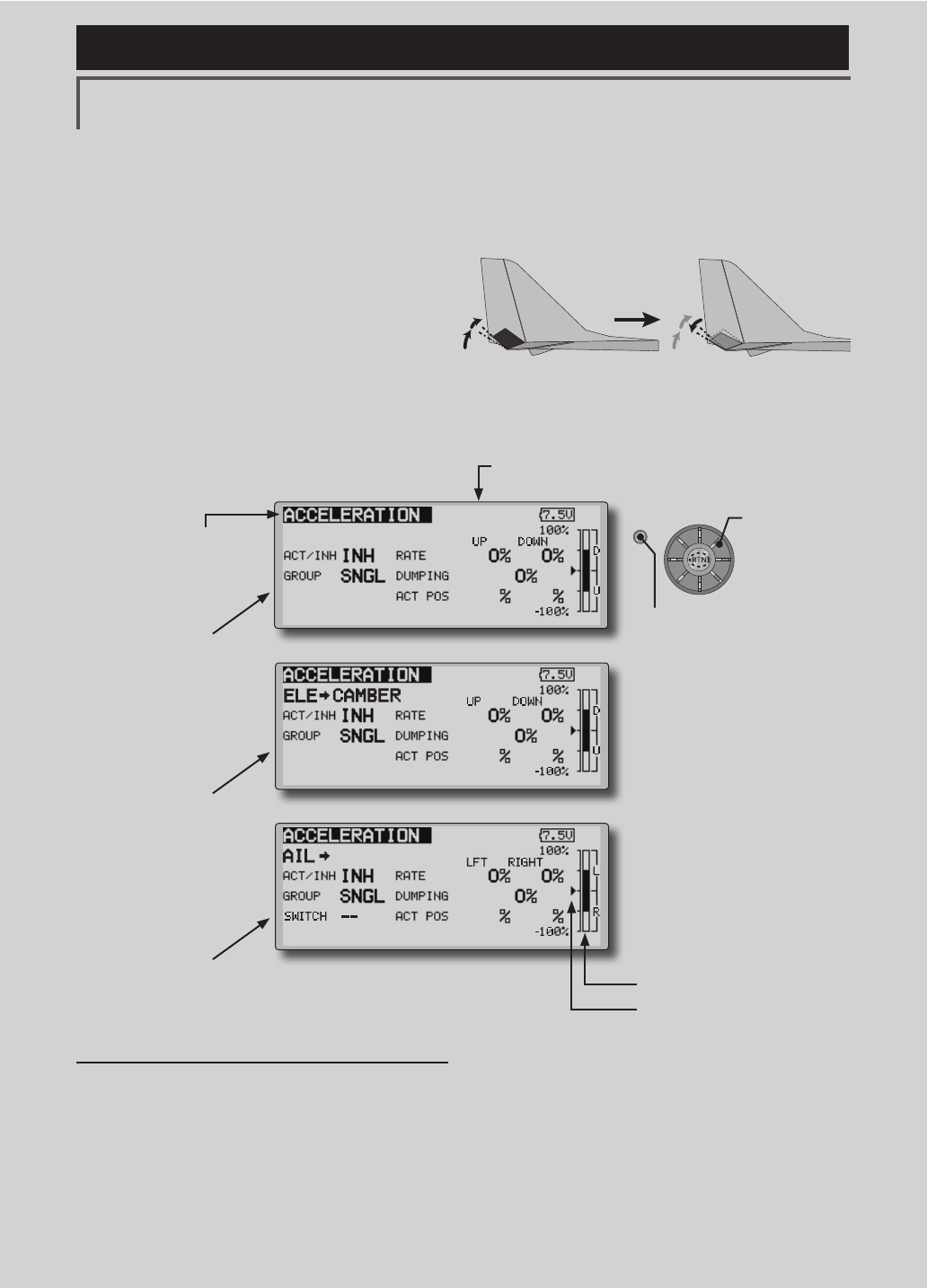
●1/3Elevatorsetting
●2/3Elevator →Cambersetting
●3/3Aileron →Ruddersetting
Setting method
●Accelerationratesetting(Rate)
●Thereturntimeafteroperation(Dumping)
canbeset.
●Theoperationpointatacceleration
anddecelerationcanbeset.Whenan
operationpointisexceeded,accelerationis
performed.
(Currently selected condition name)
●Select[ACCELERATION]atthemodelmenuand
callthesetupscreenshownbelowbypushingthe
RTNbutton.
●Actposition
●Currentposition
Acceleration setting can be performed at
elevator, ELE to Camber and AIL to RUD.(Glider
and EP glider only)
●Thissettingisdividedintoelevatorsettingand
cambersetting.Thesettingmethodisthesame.
●Cambersettingsetstheaccelerationfunctionfor
ELEtocambermixing.Settingisnotperformed
whenELEtocambermixingisINH.
●Theaccelerationfunctioncanbesetforboththe
upsideanddownside.
●FunctionON/OFFswitchsettingisperformedforAIL
toRUDsettingonly.
●AILtoRUDsettingisacceleration
functionsettingforAILtoRUDmixing.Itisnot
performedwhenAILtoRUDmixingisINH.
CONDIT1
2/3
-50 +50
CONDIT1
3/3
-50 +50
RUD
Scrolling
●Movingcursor
●Selectingmode
●Adjustingvalue
Note:Whenusingtheaccelerationfunction,
sincetheservostrokeislarge,makeyour
settingssothereisnobindingofyourlinkage.
●PushtheS1button
tocallnextpage.
145
<Model Menu (Airplane/Glider Functions) >
Reference FMT-03 is equipped with a stick of multi-copter exclusive use. Therefore it's
unsuitable for use of an airplane, a glider and a helicopter.
S1
●Selectthefunction
nameandreturntothe
precedingscreenby
pushingtheRTNbutton
orpushingtheHome/Exit
button.
<Editdial>
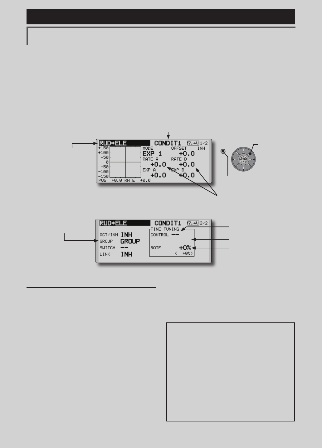
RUD to ELE [Correspondingmodeltype]:Airplane,general
This function is used when you want to mix
elevator operation with rudder operation. It is used
to correct undesirable tendencies when rudder is
applied in roll maneuvers, knife edge, etc. of stunt
planes.
●Amixingcurvecanbeset.
●MixingduringightcanbeturnedON/OFFby
settingaswitch.(AlwaysONat[--]setting)
●Linkcanbeset:Linksthismixingtoothermixings.
●Themixingratecanbene-tunedbysettingaVR.
(Finetuning)
Setting method
●MovethecursortotheACT/INHitemand
pushtheRTNbuttontoswitchtothedata
inputmode.Turntheeditdialtotheleftand
pushtheRTNbutton.(ONisdisplayed.)
●Whensettingaswitch,movethecursorto
the[--]itemoftheswitchandpushtheRTN
buttontocalltheselectionscreen,andthen
selecttheswitchandsetitsONdirection.
(AlwaysONat"--"setting)
(Foradescriptionoftheswitchselection
method,seethedescriptionatthebackof
thismanual.)
●WhensettingaVR,movethecursortothe
FineTuning"--"itemandpushtheRTNbutton
tocalltheselectionscreen,andthenselect
theVR.Thenetuningratecanbeset.
TheVRoperationmodecanalsobeset.
●Mixingcurvesetting
*For a description of the curve setting method, see
the description at the back of this manual.
●Left/rightoveralladjustmentat
rateAandrateB
(Currently selected condition name)
●Select[RUDtoELE]atthemodelmenu
andcallthesetupscreenshownbelowby
pushingtheRTNbutton.
●Group/singlemodeswitching
(For more information, refer to
the description at the back of
this manual.)
*The display screen is an example.
The actual screen depends on the
model type.
●FinetuningVRsetting
●Adjustmentrate
●Operationmode
[FinetuningVRoperationmode]
[LIN.] Mixingrate0%atcenterofVR.
WhentheVRisturnedclockwiseand
counterclockwise,themixingrate
increasesanddecreases,respectively.
[ATL+]Mixingrate0%atleftendofVR.
WhentheVRisturned,themixingrate
increases.
[ATL-] Mixingrate0%at rightendofVR.
WhentheVRisturned,themixingrate
increases.
[SYM.]WhentheVRisturnedtotheleftor
rightoftheneutralposition,themixing
rateincreases.
(ForadescriptionofthenetuningVRsetting
method,seethedescriptionatthebackof
thismanual.)
●WhensettingLink,movethecursortotheLink
itemandpushtheRTNbuttontoswitchto
thedatainputmode.SetittoON.
Scrolling
●Movingcursor
●Selectingmode
●Adjustingvalue
●PushtheS1button
tocallnextpage.
146 <Model Menu (Airplane/Glider Functions) >
Reference FMT-03 is equipped with a stick of multi-copter exclusive use. Therefore it's
unsuitable for use of an airplane, a glider and a helicopter.
S1
●Selectthefunction
nameandreturntothe
precedingscreenby
pushingtheRTNbutton
orpushingtheHome/Exit
button.
<Editdial>
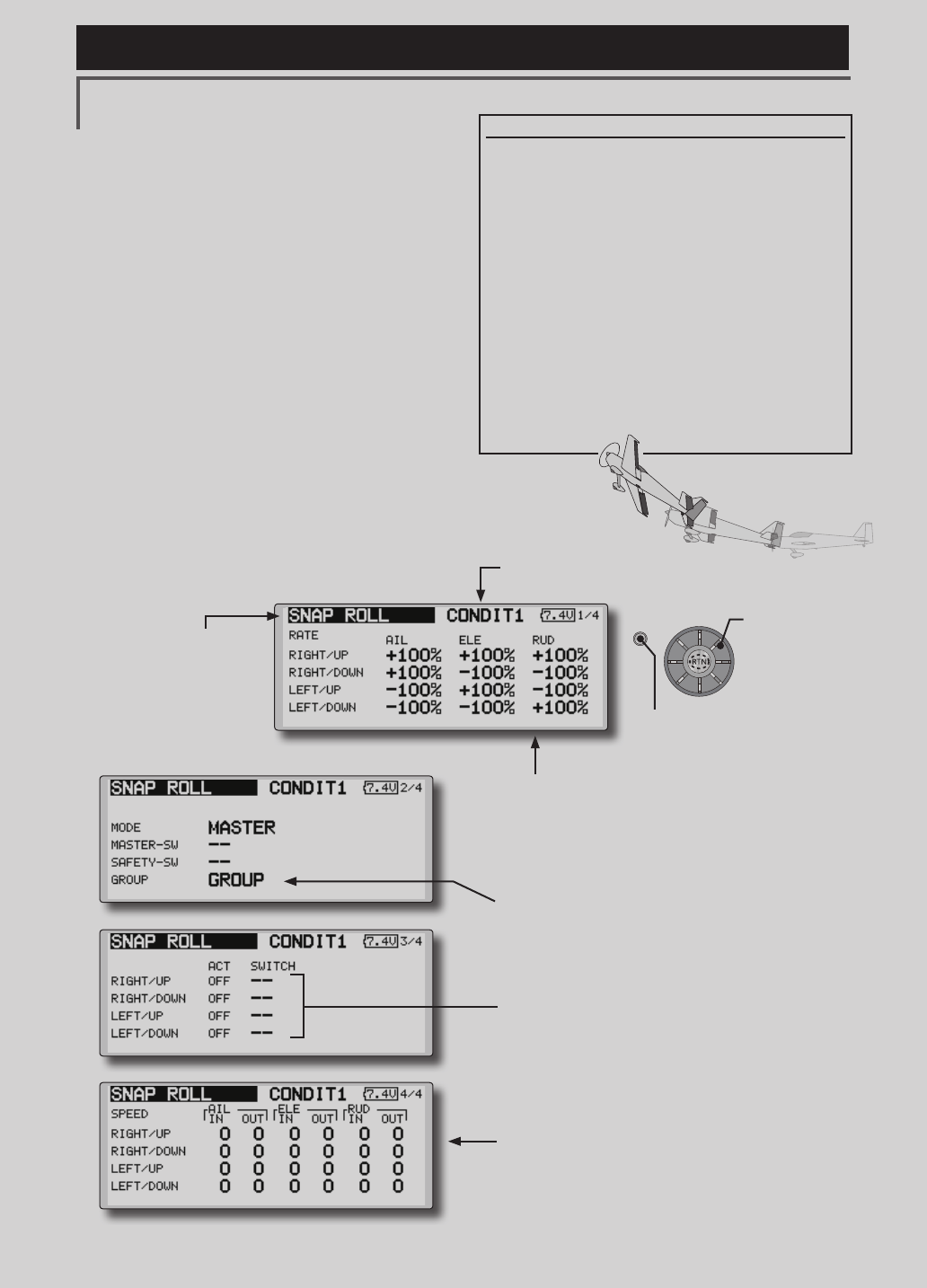
SNAP ROLL [Correspondingmodeltype]:Airplane,general
This function selects the switch and rate
adjustment of each rudder, (ailerons, elevators, or
aps) when a snap roll is performed.
●Foursnaprolldirectionscanbeset.(Right/up,right/down,
left/up,left/down)
●Operationmode:When[Master]modeisselected,the
SnapRollfunctionisturnedON/OFFbymasterswitchin
thestateinwhichthedirectionswitchwasswitchedto
thedirectioninwhichyouwanttosnaproll.When[Single]
modeisselected,snaprollineachdirectioncanbe
executedbymeansofindependentswitches.
●Asafetyswitchcanbeset.Asasafetymeasure,the
switchcanbesetsothatsnaprollisnotexecutedwhen,
forinstance,thelandinggearislowered,evenifthe
switchisturnedonaccidentally.Thesnaprollswitchis
activatedonlywhenthesafetyswitchisON.
●Theoperationspeedoftheaileron,elevator,andap
servoscanbeadjustedforeachsnaprolldirection.(In
side/outside)
(Example) Setting example for F3A
●Mode:[Master]
●SafetySW:[SW-G](Safetymeasure)
●MasterSW:[SW-H](Mainswitchfor
executingsnaproll)
●Directionswitches:
*The snap roll up side left and right and down side left and right
direction switches are selected here.
Right/Up:OFF[SW-D]
Right/Down:OFF[SW-D]
Left/Up:OFF[SW-A]
Left/Down:OFF[SW-A]
●Speedadjustment
Theoperationspeedofeachcontrolsurfacewhen
thesnapswitchisONcanbechangedandsnaproll
executedbystickwhilethereisswitchoperationcanbe
performed.
●Rateadjustment
1.Movethecursortotheitemyouwantto adjust and
pushtheRTNbuttontoswitchtothedatainputmode.
2.Adjustratebyscrollingtheeditdial.
3.PushtheRTNbuttontoendadjustmentandreturnto
thecursormovemode.
●Group/singlemodeswitching
(For more information, see the description at the back of this
manual.)
●Directionswitches
●Adjustmentoftheservospeedofeachrudder
(For a description of the setting method, see the
description at the back of this manual.)
(Currently selected condition name)
●Select[SNAPROLL]atthemodelmenuandcall
thesetupscreenshownbelowbypushingtheRTN
button.
Scrolling
●Movingcursor
●Selectingmode
●Adjustingvalue
●PushtheS1button
tocallnextpage.
147
<Functions of Model Menu (Helicopter Functions) >
Reference FMT-03 is equipped with a stick of multi-copter exclusive use. Therefore it's
unsuitable for use of an airplane, a glider and a helicopter.
S1
●Selectthefunction
nameandreturntothe
precedingscreenby
pushingtheRTNbutton
orpushingtheHome/Exit
button.
<Editdial>
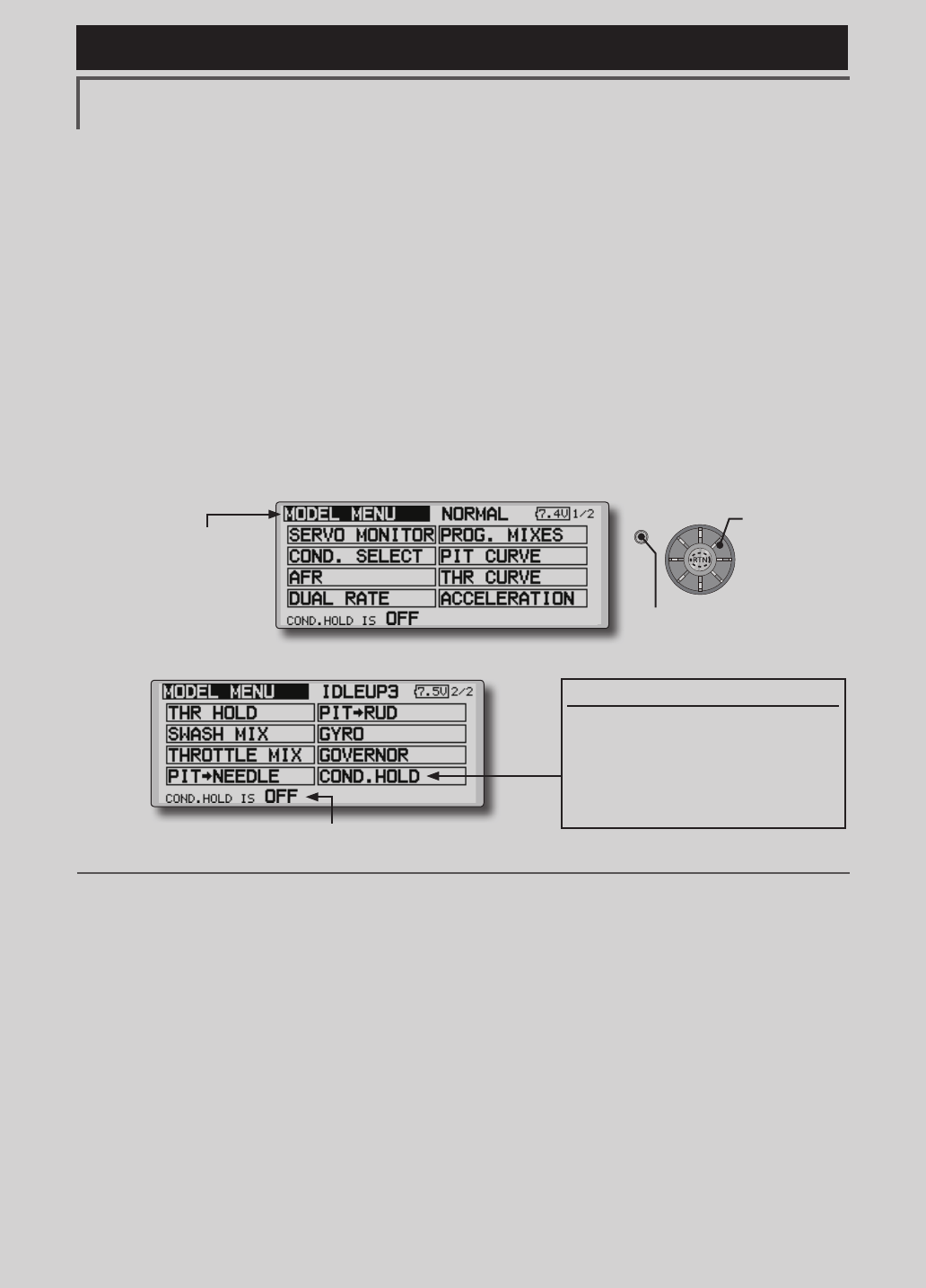
MODEL MENU (HELICOPTER)
This section contains information on the
commands that apply to helicopters only. For
instructions on airplanes and sailplanes, refer to the
sections pertaining to those aircraft.
Use the Model Type function in the Linkage
Menu to select the swash type matched to the
fuselage beforehand.
Also, add flight conditions at the Condition
Select screen if necessary before setting the model
data at each function. (Up to 8 conditions can be
used)
The AFR function, dual rate function and other
functions common to all model types, are described
in a separate section.
Model Menu functions (helicopter) list
PIT CURVE: Adjusts response in different ight conditions
THR CURVE: Throttle curve and hovering trim adjustment
ACCELERATION: Allows a brief "overload" in response to sudden throttle and pitch commands
THR HOLD: Moves the throttle to idle during autorotation
SWASH MIX: Compensates for each control response
THROTTLE MIX: Compensates for power loss when cyclic applied
PIT to NEEDLE: Adjusts response curve in different ight conditions
PIT to RUD: Handles torque changes from pitch angle inputs
GYRO: Used to switch gyro sensitivity
GOVERNOR: Used to switch RPM of the helicopter’s head
To activate/deactivate Condition Hold:
1.Movethecursorto[COND.HOLD].
2.Setthethrottlesticklowerthanthe
1/3pointandpushtheRTNbuttonto
activate/deactivatethecondition
holdfunction.
*Refer to for condition hold function details.
*Condition hold operation is displayed.
●Selectthe[MODEL]atthehomescreenandcallthemodel
menushownbelowbypushingtheRTNbutton.
●Usetheeditdialtoselectthefunctionyouwanttosetand
callthesetupscreenbypushingtheRTNbutton.
Scrolling
●Movingcursor
●PushtheS1button
tocallnextpage.
148 <Functions of Model Menu (Helicopter Functions) >
Reference FMT-03 is equipped with a stick of multi-copter exclusive use. Therefore it's
unsuitable for use of an airplane, a glider and a helicopter.
CH
H-4/H-4XSwash
AllOther
1Aileron Aileron
2Elevator Elevator
3
Throttle Throttle
4
Rudder Rudder
5Gyro Gyro
6
Pitch Pitch
7Governor
Governor
8Elevator2
Governor2
9GYRO2 GYRO2
10 GYRO3 GYRO3
11
Governor2 Needle
12
Needle AUX5
13
AUX4
14
AUX3
15
AUX2
16
AUX1
DG1
SW
DG2
CH
H-4/H-4XSwash
AllOther
1Aileron Aileron
2Elevator Elevator
3
Throttle Throttle
4
Elevator2 Rudder
5Pitch Pitch
6
Gyro Gyro
7Governor
Governor
8Rudder
Governor2
9GYRO2 GYRO2
10 GYRO3 GYRO3
DG1
SW
DG2
Helicopter
●FASSTest 18CH
●FASSTest 12CH
Servo connection by Helicopter type
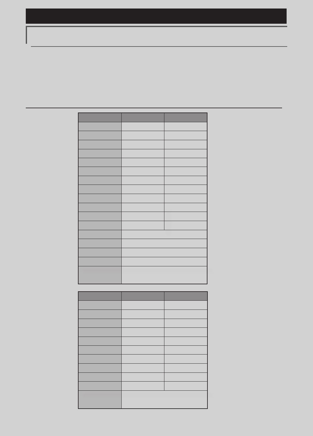
The FMT-03 transmitter channels are automatically assigned for optimal combination according to the
type selected with the Model Type function of the Linkage Menu. The channel assignment (initial setting)
for helicopter type is shown below. Connect the receiver and servos to match the type used.
*The set channels can be checked at the Function screen of the Linkage Menu. The channel assignments can also be changed.
For more information, read the description of the Function menu.
149
<Functions of Model Menu (Helicopter Functions) >
Reference FMT-03 is equipped with a stick of multi-copter exclusive use. Therefore it's
unsuitable for use of an airplane, a glider and a helicopter.
S1
●Selectthefunction
nameandreturntothe
precedingscreenby
pushingtheRTNbutton
orpushingtheHome/Exit
button.
<Editdial>
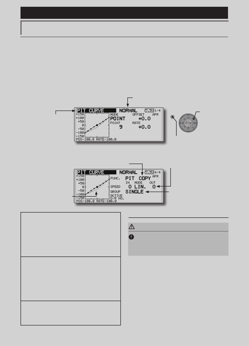
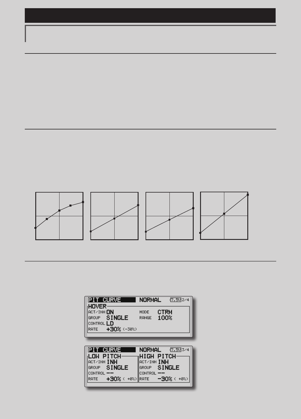
PIT CURVE/PIT TRIM
PIT Curve
This function adjusts the pitch operation curve
for each ight condition for the optimal ight state
relative to movement of the throttle stick.
*Up to 17 points can be set for the point curve types.
However, when using the 3 points or 5 points specied to
create a curve, a simple curve can be created by reducing
the number of input points to 3 or 5, and then entering the
specied value at the corresponding points that you created
a curve.
●Pointcurvetypeis9points(initial),but
forsimpleuse,4~5pointsaresufcient.
Normal curve adjustment
●Fornormalcurve,usuallyuse[POINT]type
andcreateabasicpitchcurvecentered
abouthovering.Usethisfunctiontogether
withtheTHRcurve(normal)functionand
adjustthecurvesothatup/downcontrolis
bestataconstantenginespeed.
Idle up curve adjustment
●Forthehighsidepitchcurve,setthe
maximumpitchwhichdoesoverloadthe
engine.Forthelowsidepitchcurve,create
curvesmatchedtoloop,roll,3D,and
otherpurposesandusetheidleupcurves
accordingtotheperformance.
Throttle hold curve adjustment
●Thethrottleholdcurveisusedwhen
executingautorotationdives.
Operation precautions
WARNING
When actually starting the engine and ying,
always set the idle up condition switch to
OFF and start the engine in the idling state.
(Currently selected condition name)
●Select[PITCURVE]atthemodelmenuandcall
thesetupscreenshownbelowbypushingtheRTN
button.
●Group/singlemodeswitching
(For more information, refer to the
description at the back of this manual.)
●Mixingcurvesetting
*For a description of the curve setting method, see the
description at the back of this manual.
●Pitchservospeedsetting
(For a description of the setting method,
see the description at the back of this
manual.)
●Pitchtrimcopy
●Pitchtrimoperating
position(dottedline)
Scrolling
●Movingcursor
●Selectingmode
●Adjustingvalue
●PushtheS1button
tocallnextpage.
150 <Functions of Model Menu (Helicopter Functions) >
Reference FMT-03 is equipped with a stick of multi-copter exclusive use. Therefore it's
unsuitable for use of an airplane, a glider and a helicopter.
Normal Curve Idle-up 1 Curve Idle-up 2 Curve Hold Curve
●Pitch Curve (Example)
●Group/Singleitem:Whenyoualsowantto
inputthesamesettingcontentsatother
conditions,performsettinginthegroup
mode.Inthiscase,thesamecontentsare
inputtotheotherconditionssetinthegroup
mode.Whenyouwanttoseteachcondition
independently,selectthesinglemode
(initialsetting).Otherconditionscanbeset
independently.
Setting method
●Pittrimcopy(Hover/high/low)
Thepitchtrimoperatingpositioncanbe
copiedtothepitchcurve.
Movethecursortothe[COPY]itemand
pushtheRTNbutton.
Aftercopying,returnthepitchtrimtothe
centertocallthelastoperatingposition.
The screens shown below are curves created
by entering the pitch rate at low, center, and high
side (3 points or 5 points) at each condition. When
actually creating a curve, input the rate specied at
the fuselage (or the reference value).
*For a description of the curve setting method, see the
description at the back of this manual.
Curve setting examples
(Continued on next page)
Pitch Trim (Hovering pitch, high pitch, low pitch)
The hovering pitch, low pitch, and high pitch trim setup screen can be called from the PIT curve setup
screen.
●Hoveringpitchtrim
setting
●Low/highpitchtrim
setting

151
<Functions of Model Menu (Helicopter Functions) >
Reference FMT-03 is equipped with a stick of multi-copter exclusive use. Therefore it's
unsuitable for use of an airplane, a glider and a helicopter.
Hovering pitch trim
The Hovering Pitch trim function trims the pitch
near the hovering point. Normally, it is used with
the hovering condition. The hovering pitch can be
ne tuned for changes in rotor speed accompanying
changes in temperature, humidity, and other ight
conditions. Adjust the hovering pitch so that
rotor speed is constant. This function can be used
together with the hovering Throttle Trim function
for more delicate operation.
Setting method
●Whenusingonlythehovering(normal)
condition,switchthegroupmodetothe
singlemode(initialsetting)beforesetting.
●SetthefunctiontoACT[ON].
●Selecttheadjustmentknob.
●Thetrimoperationmode(Mode:CTRM/
NORM)canbeselected.
CTRMmode:Maximumamountofchange
nearcenterbycentertrimoperation
(recommended)
NORMmode:Normaltrim(parallel
movementtrim)operation.Theadvantage
ofusingthismodeisthatthehoveringpitch
canbeadjustedwithoutchangingthe
curve.
●Trimadjustmentrange(Range)setting
Whenthisvalueismadesmall,trimcanonly
beusednearthecenter.
●Thetrimratecanbeadjustedandthe
operationdirectioncanbechanged.
High Pitch/Low Pitch Trim
High Pitch/Low Pitch Trim is the pitch servo
high side and low side trim function.
Setting method
●Whensettingtheadjustmentknobscommon
toalltheconditions,settheminthegroup
mode.
●SetthefunctiontoACT(ON).
●Selecttheadjustmentknobs.
●Thetrimratecanbeadjustedandthe
operationdirectioncanbechanged.
●Trimactsashighsideorlowsidetrimwiththe
centerasthestandard.
152 <Functions of Model Menu (Helicopter Functions) >
Reference FMT-03 is equipped with a stick of multi-copter exclusive use. Therefore it's
unsuitable for use of an airplane, a glider and a helicopter.
S1
●Selectthefunction
nameandreturntothe
precedingscreenby
pushingtheRTNbutton
orpushingtheHome/Exit
button.
<Editdial>
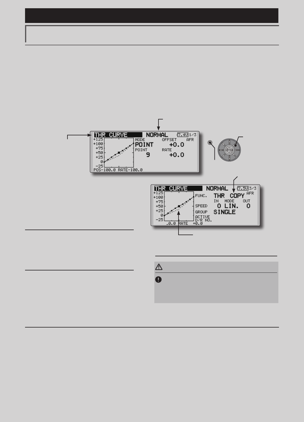
THR CURVE/THROTTLE HOVER TRIM
THR Curve
This function adjusts the throttle operation curve
for each condition for optimum engine speed to
throttle stick movement.
Up to 17 curve points can be set for the point
curve type, however, when the 5 points and other
point data is used, a simple curve can be easily
created by reducing the number of input points of
the curve to 5 and entering the specified value at
the corresponding points.
Normal curve adjustment
●Normalcurvecreatesabasiccurve
centeredaroundhovering.Useitalong
withthenormalpitchcurveandadjustso
thatup/downcontrolataconstantengine
speediseasiest.
Idle up curve adjustment
●Setaidleupcurvethatmaintainsaconstant
speedatalltimes,evenduringoperation
whichreducesthepitchperformedinight.
Createacurvematchedtoloop,roll,3D,
orotherpurposesandtheidleupcurve
accordingtotheperformance.
Operation precautions
WARNING
When actually starting the engine and flying,
always set the idle up condition switch to OFF
and start the engine in the normal/motor at idle
mode.
Setting method
●Group/singleitem:Whenyouwantto
simultaneouslyenterthesamesettingstoother
functions,makethesettingsinthegroupmode.In
thiscase,thesamesettingcontentsareentered
totheallconditions.Whenyouwanttoseteach
conditionindependently,makethesettingsafter
selectingthesinglemode(Initialsetting).
●Throttlehovertrimcopy
Thethrottlehover trimoperatingpositioncanbe
copiedtothethrottlecurve.
Movethecursortothe[COPY]itemandpushthe
RTNbutton.
Aftercopying,returnthepitchtrimtothecenterto
callthelastoperatingposition.
(Currently selected condition name)
●Select[THRCURVE]atthemodelmenu and call
thesetupscreenshownbelowbypushingtheRTN
button.
●Mixingcurvesetting
*For a description of the curve setting method,
see the description at the back of this manual.
●Throttlehovertrim
copy
●Throttlehovertrimoperatingposition
(dottedline)
Scrolling
●Movingcursor
●Selectingmode
●Adjustingvalue
●PushtheS1button
tocallnextpage.
153
<Functions of Model Menu (Helicopter Functions) >
Reference FMT-03 is equipped with a stick of multi-copter exclusive use. Therefore it's
unsuitable for use of an airplane, a glider and a helicopter.
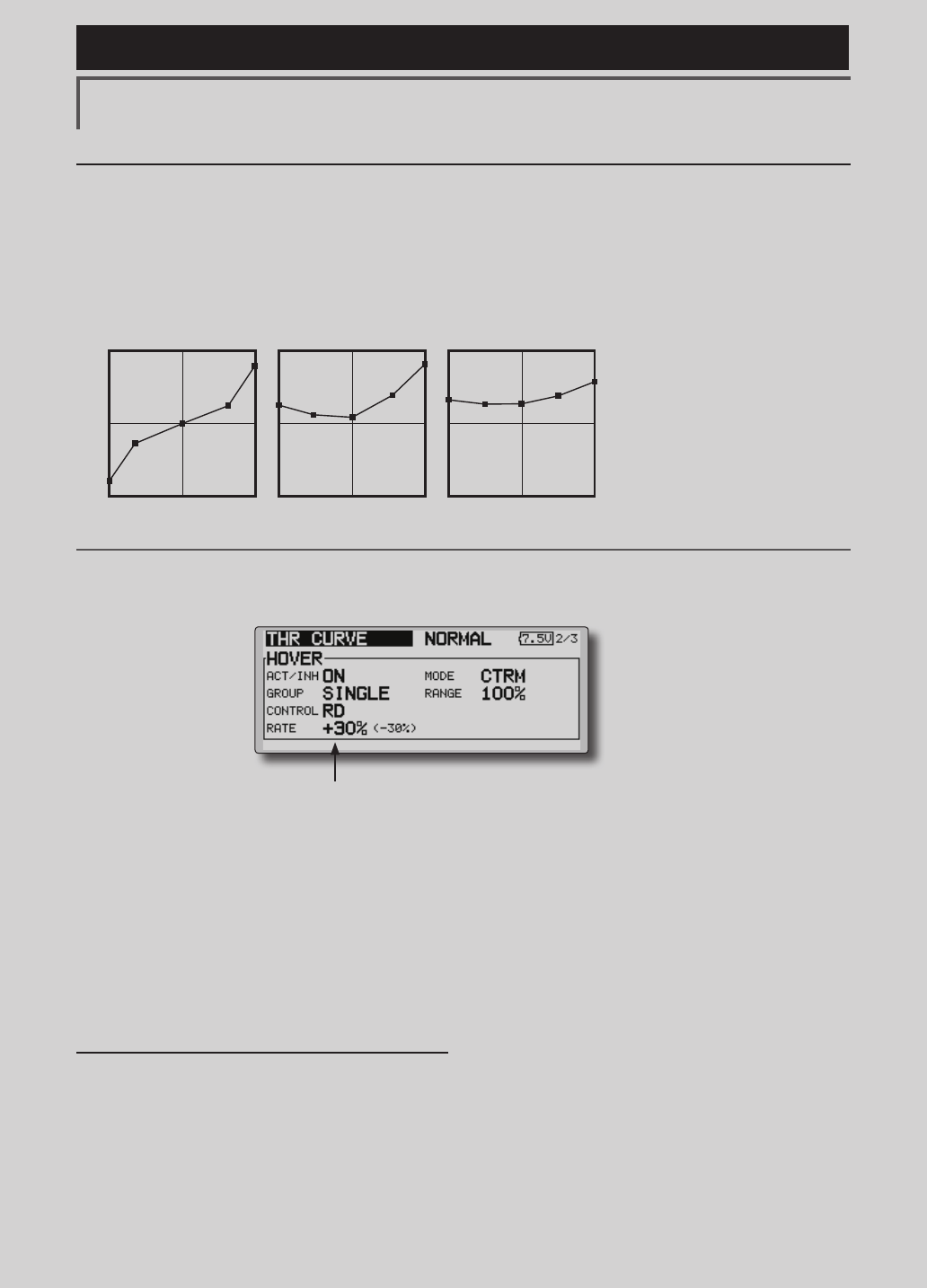
Normal Curve Idle-up 1 Curve Idle-up 2 Curve
●Throttle Curve (Example)
The curves shown below are created by using
the point curve type and inputting the data of the
5 points 0% (low side), 25%, 50% (center), 75%,
100% (high) side at each condition. They are
created by reducing the number points of the line
to 5. When actually creating a curve, enter the data
specied per the aircraft (or the reference value).
*For a description of the curve creation method, see the
description at the back of this manual.
Curve setting examples
Throttle Hover trim
The Throttle Hover trim setup screen can be called from the THR Curve setup screen.
The Throttle Hover function trims the throttle
near the hovering point. Normally, use it with
hovering conditions. Changes in rotor speed
accompanying changes in the temperature,
humidity, and other flight conditions can be
trimmed. Adjust the throttle so that rotor rotation is
most stable. More delicate trimming is also possible
by using this function along with the Hover Pitch
function.
Setting method
●Whenusingthehovering(normal)condition
only,switchthegroupmodetothesingle
mode(initialsetting)andmakethesettings.
●SetthefunctiontoACT([ON]).
●Selecttheadjustmentknob.
●Thetrimoperationmode(Mode:CTRM/
NORM)canbeselected.
CTRMmode:Maximumrateofchange
nearcenterbycentertrimoperation
(recommended)
NORMmode:Normaltrim(horizontal
movementtrim)operation.
●Trimadjustmentrange(Range)setting
Whenthevalueismadesmall,trimactsonly
nearthecenter.
●Thetrimratecanbeadjustedandthe
operationdirectioncanbeset.
●Setsthedialused.
154 <Functions of Model Menu (Helicopter Functions) >
Reference FMT-03 is equipped with a stick of multi-copter exclusive use. Therefore it's
unsuitable for use of an airplane, a glider and a helicopter.
Setting method
●Activatethefunction
1.Select"ACT/INH"andpushtheRTNbutton.
2.Scrollingtheeditdialandswitchthedisplay
to[INH]or[ACT].
3.PushtheRTNbutton.
●Group/singlemodeselection.
1.Select"GROUP"andpushtheRTNbutton.
2.Scrollingtheeditdialandswitchthedisplay
to[GROUP]or[SINGLE].
3.PushtheRTNbutton.
●ON/OFFswitchsetting
1.Select"SWITCH"andpushtheRTNbutton.
2.Ahardwareselectionscreenisdisplayed.
SelectthehardwareandpushtheRTN
button.
●Highsideoperationrangesetting
1.Select"HIGH"andpushtheRTNbutton.
2.Scrollingtheeditdialandadjustthehighside
operationrange.
3.PushtheRTNbutton.
●Lowsideoperationrangesetting
1.Select"LOW"andpushtheRTNbutton.
2.Scrollingtheeditdialandadjustthelowside
operationrange.
3.PushtheRTNbutton.
●Theneutralpositionof"CONTROL"setting
1.Select"CENTER"andpushtheRTNbutton.
2.Scrollingtheeditdialandadjust theneutral
position.
3.PushtheRTNbutton.
●Limiteractivationpositionadjustmentcontrol
setting
1.Select"CONTROL"andpushtheRTNbutton.
2.Ahardwareselectionscreenisdisplayed.
SelectthehardwareandpushtheRTN
button.
Throttle Limiter
*When the limiter operation range adjustment control is
NULL, the throttle limiter function is not activated.
This function limits throttle operation to within a
certain range. Control which adjusts the operating
range during ight can be set. (Effective only when
the model type is helicopter.)
●OpentheTHRCURVEsetup
screen.PushS1buttontoadvance
tonextpageanddisplaypage4.
●Throttlelimiteractivation
position
●Conditiongroup/single
●Throttlelimiterfunction
ACT/INH
●MixingON/OFFswitch
●Limiteractivationposition
adjustmentcontrol
●Thelimitvalueattheoperationhardwareneutral
positioncanbeadjustedusingthethrottlelimiter.
●Highsideoperationrange
●Lowsideoperationrange
●WhenCENTERisINH.
Themotionwiththeequal
upperandlowersidesis
carriedout.
●WhenCENTERis28%.
Theamountofoperations
aboveCONTROLincreases.
Thehighsideofa
throttlecanrestrict
tothisrangeby
CONTROL.
The neutral position of
CONTROL
The neutral position of
CONTROL
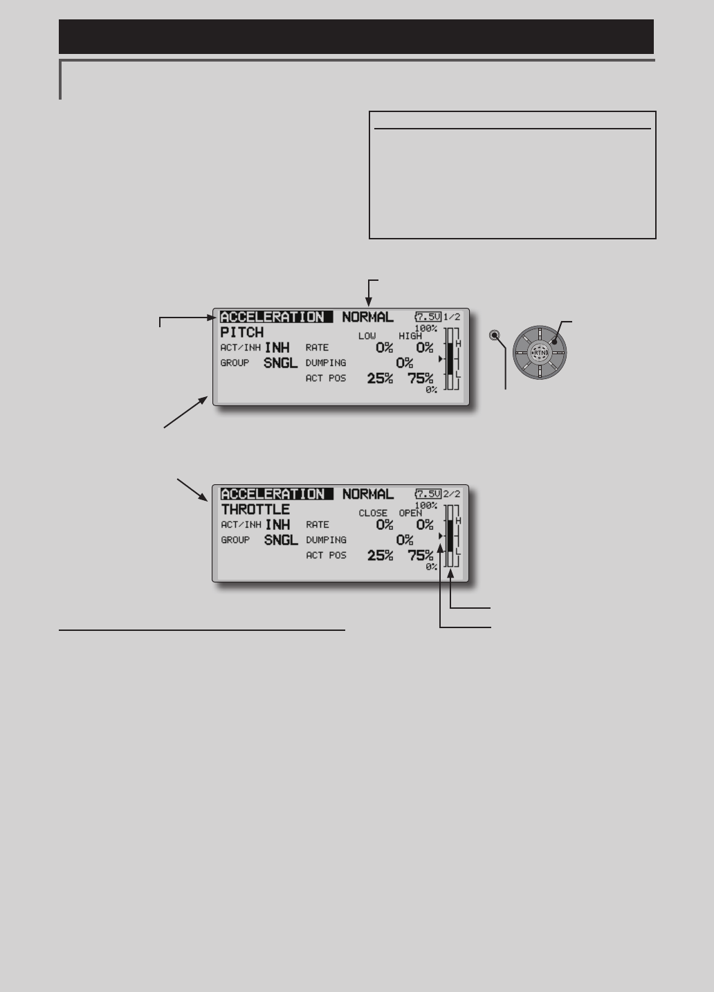
155
<Functions of Model Menu (Helicopter Functions) >
Reference FMT-03 is equipped with a stick of multi-copter exclusive use. Therefore it's
unsuitable for use of an airplane, a glider and a helicopter.
S1
●Selectthefunction
nameandreturntothe
precedingscreenby
pushingtheRTNbutton
orpushingtheHome/Exit
button.
<Editdial>
ACCELERATION
This function is used to adjust the pitch and
the throttle rise characteristic at acceleration/
deceleration operation. An acceleration function
which temporarily increases the pitch and throttle
operations at throttle stick acceleration/deceleration
operation can be set.
Example of acceleration function use
●Whenusedforpitchcontrol,the
accelerationfunctioniseffectivewhenyou
wanttoquickentheresponseofthemodel
at3Doncollectivepitch.
Whenused,highpitchtemporarilyexceeds
maximumpitch,butimmediatelyreturnsto
maximumpitch.
●Pitchsetting
●Throttlesetting
Setting method
●Accelerationcanbesetatbothsetting
atacceleration(high)andsettingat
deceleration(low).
(Theoperationpointisdisplayedona
graph.)
●Accelerationratesetting(Rate)
●Thereturntimeafteroperation(Dumping)
canbeset.
●Theoperationpointatacceleration
anddecelerationcanbeset.Whenan
operationpointisexceeded,accelerationis
performed.
Note:Whenusingtheaccelerationfunction,
sincethepitchstrokeislarge,makeyour
settingssothereisnobindingofyourlinkage.
(Currently selected condition name)
●Select[ACCELERATION]atthemodelmenuand
callthesetupscreenshownbelowbypushingthe
RTNbutton.
●Actposition
●Currentposition
Scrolling
●Movingcursor
●Selectingmode
●Adjustingvalue
●PushtheS1button
tocallnextpage.
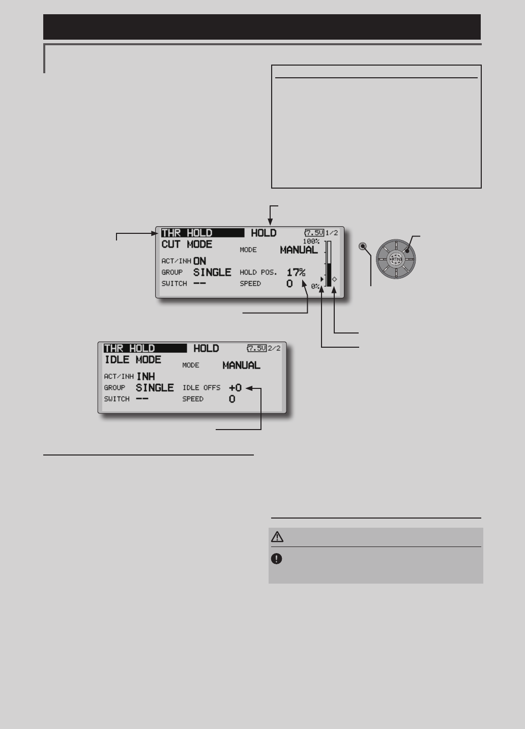
156 <Functions of Model Menu (Helicopter Functions) >
Reference FMT-03 is equipped with a stick of multi-copter exclusive use. Therefore it's
unsuitable for use of an airplane, a glider and a helicopter.
S1
●Selectthefunction
nameandreturntothe
precedingscreenby
pushingtheRTNbutton
orpushingtheHome/Exit
button.
<Editdial>
THR HOLD
This function sets the throttle cut position for
auto rotation. The throttle position can also be set
to an idling position. Setting of these 2 positions
can be selected by a switch. This allows use for
switching during training.
Example of use
●Sincethrottleholdhas2modes(Cut)and
(Idle),usingitintheIdlingmodeduring
trainingandinthe Cutmodewhen
stoppingtheengine.
Note:WhenthrottleholdissettoONinthenormal
condition,throttleholdactsandthethrottleservo
isdeactivated.AlwayssetthrottleholdtoONinthe
holdcondition.
●Settotheenginestopposition.
●Settotheidlingposition.
Setting method
●Operationmodeselection
Manualmode(MANUAL):Thethrottlehold
functionisoperatedbyswitchoperation
only.
Automode(AUTO):Thethrottleholdfunction
operationislinkedtothethrottlestick
position.
Autopositionsetting:Whentheautomodeis
selected,thethrottleposition(autoposition)
canbeselected.Movethethrottlestickto
thepositionyouwanttosetandpushthe
RTNbutton.(Autopositionisdisplayed.)
●Holdpositionadjustment
ThrottleHold(Cut)setsthethrottlecut
position.Adjustitsothatthecarburetorisfull
close.
ThrottleHold(Idle):Makethisadjustmentto
maintainidling.Adjustmentscanbemade
basedonthethrottlecurveidleposition.
●Thethrottleservooperatingspeedcanbe
adjusted.(Speed)
●Throttlecutortrainingfunctioncanbe
switchedbyholdfunctionselectorswitch.
Operation precautions
WARNING
When starting the engine, conrm that the idle up
condition and throttle hold condition are OFF.
(Currently selected condition name)
●Select[THRHOLD]atthemodelmenu
andcallthesetupscreenshownbelowby
pushingtheRTNbutton.
●Holdposition
●Currentposition
Scrolling
●Movingcursor
●Selectingmode
●Adjustingvalue
●PushtheS1button
tocallnextpage.
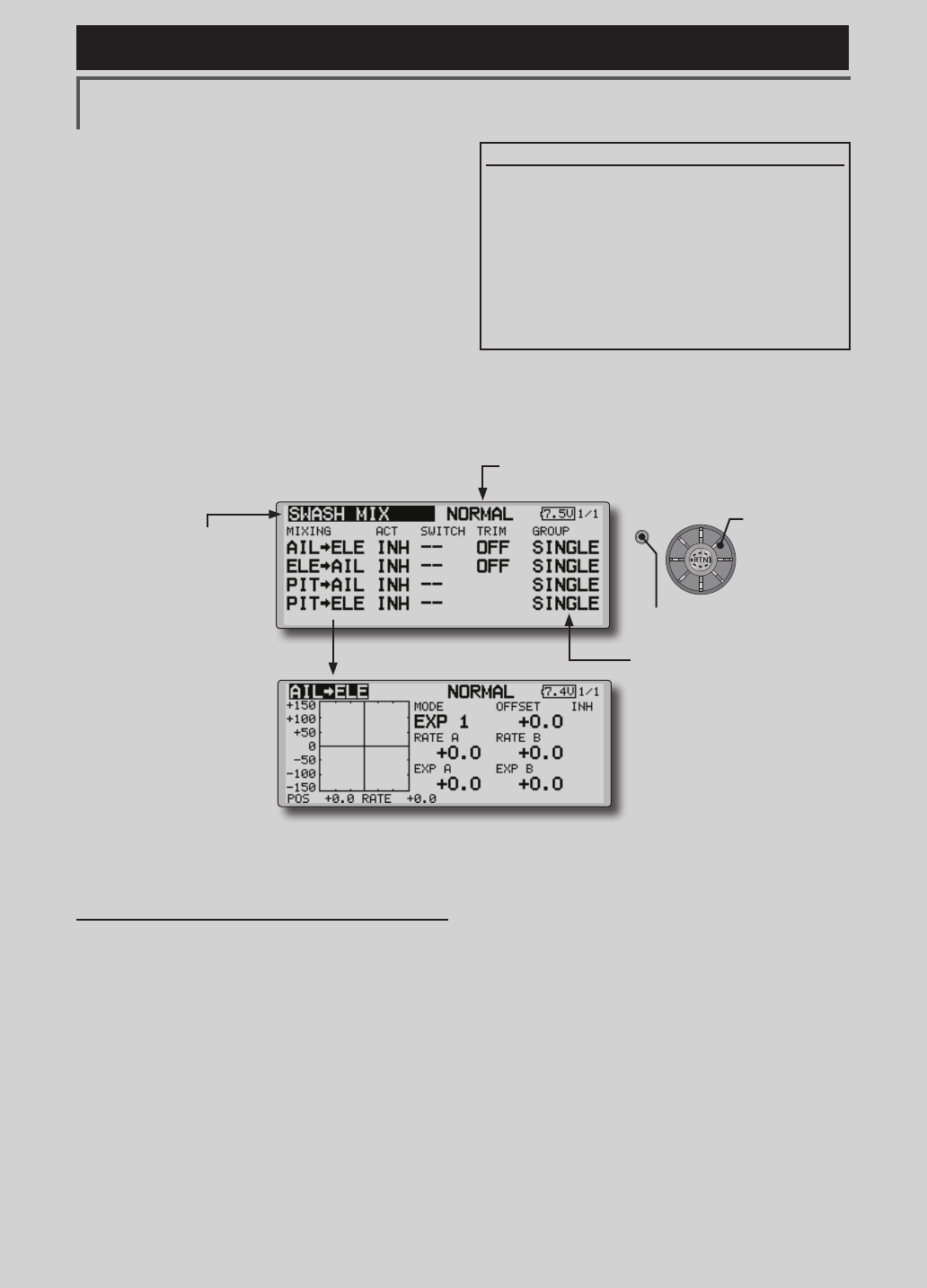
157
<Functions of Model Menu (Helicopter Functions) >
Reference FMT-03 is equipped with a stick of multi-copter exclusive use. Therefore it's
unsuitable for use of an airplane, a glider and a helicopter.
S1
●Selectthefunction
nameandreturntothe
precedingscreenby
pushingtheRTNbutton
orpushingtheHome/Exit
button.
<Editdial>
SWASH MIX
The swash mix function is used to correct the
swash plate in the aileron (roll) direction and
elevator (cyclic pitch) corresponding to each
operation of each condition.
Adjustment by independent curve for aileron,
elevator, and pitch operations is possible. The
operation can be smoothly adjusted by calling up
the “Curve setup” screen by pushing the EDIT
button with moving the cursor to the mixing item
that corresponds to the mixing and direction which
needs correction.
Example of use
●Asanexample,useswashmixingtocorrect
undesirabletendenciesintherolldirection
●ForaconditionwhichusesAILtoELE,setthis
functiontoON.Whenraisingthenoseata
rightroll,whentheRateBsideisinputand
therightaileronisoperated,theelevator
movestothedownside.Tunebyadjusting
theRate.Forrightroll,adjusttotherateA
side.
Setting method
●Whenusingthisfunction,movethecursorto
the[ACT]itemandpushtheRTNbuttonto
switchtothedatainputmode.Turntheedit
dialtotheleftandpushtheRTNbutton.(ON
isdisplayed.)
●Whenyouwanttosetthesamecontentsat
otherconditions,selectthegroupmode.
Whenyouwanttosettheselectedcondition
only,selectthesinglemode(initialsetting).
●Thecorrectionratecanbesetbycurve.
● Aswitchcanbeset.
When[--]isset,theswashmixingfunctionis
operatedbymerelyselectingthecondition.
Whensettingan[ON]/[OFF]switch,move
thecursortothe[--]itemandpushtheRTN
buttontocalltheselectionscreenandset
theswitchanditsONposition.
(Currently selected condition name)
●Select[SWASHMIX]atthemodelmenu
andcallthesetupscreenshownbelow
bypushingtheRTNbutton.
●Group/singlemodeswitching
(For more information, refer to the
description at the back of this manual.)
●Mixingcurvesetting
*For a description of the curve setting method, see the
description at the back of this manual.
Scrolling
●Movingcursor
●Selectingmode
●PushtheS1button
tocallnextpage.
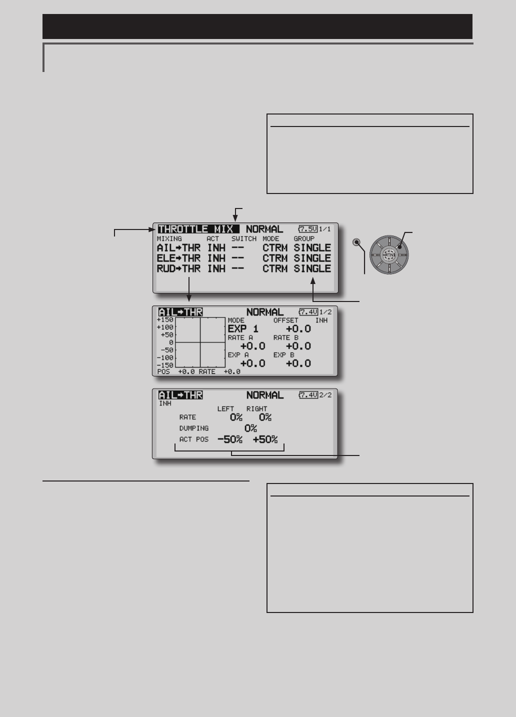
158 <Functions of Model Menu (Helicopter Functions) >
Reference FMT-03 is equipped with a stick of multi-copter exclusive use. Therefore it's
unsuitable for use of an airplane, a glider and a helicopter.
S1
●Selectthefunction
nameandreturntothe
precedingscreenby
pushingtheRTNbutton
orpushingtheHome/Exit
button.
<Editdial>
THROTTLE MIX
This function corrects slowing of engine speed
caused by swash plate operation during aileron
or elevator operation. The method of applying
clockwise or counterclockwise torque when
pirouetting can also be corrected.
An acceleration function which temporarily
increases the throttle side correction rate relative to
rapid stick operation can also be set.
Setting example
●AILtoTHRappliesaloadtotheengineand
correctsslowingoftheenginespeedwhen
theaileronstickwasoperated.Engine
racingcanbeadjustedindependentlyat
therightaileronandleftaileronbyRatesA
andB.
Setting method
●Whenusingthisfunction,movethecursorto
the[ACT]itemandpushtheRTNbuttonto
switchtothedatainputmode.Turntheedit
dialtotheleftandpushtheRTNbutton.(ON
isdisplayed.)
●Whenyouwanttosetthesamecontentsat
otherconditions,selectthegroupmode.
Whenyouwanttosettheselectedcondition
only,selectthesinglemode(initialsetting).
●Thecorrectionratecanbesetbycurve.
●Aswitchcanbeset.
When[--]isset,theswashmixingfunctionis
operatedbymerelyselectingthecondition.
Whensettingan[ON]/[OFF]switch,move
thecursortothe[--]itemandpushtheRTN
buttontocalltheselectionscreenandset
theswitchanditsONposition.
When correction is necessary, move the cursor
to the mixing item corresponding to the mixing
that needs correction and push the RTN button to
call the curve setup screen, and then correct the
slowing.
<Acceleration function setting>
●Accelerationcanbesetforbothsettings
(Left)and(Right)
●Accelerationratesetting(Rate)
●Thereturntime(Dumping)afteroperation
canbeset.
●Theoperationpointwhenthecorrection
rateisincreasedand decreasedcanbe
setindependently.Whenanoperation
pointisexceeded,accelerationoperation
isperformed.
(Currently selected condition name)
●Select[THROTTLEMIX]atthemodel
menuandcallthesetupscreenshown
belowbypushingtheRTNbutton.
●Group/singlemodeswitching
(For more information, refer to
the description at the back of this
manual.)
●Mixingcurvesetting
*For a description of the
curve setting method, see
the description at the back of
this manual.
●Accelerationsettings
Scrolling
●Movingcursor
●Selectingmode
●PushtheS1button
tocallnextpage.
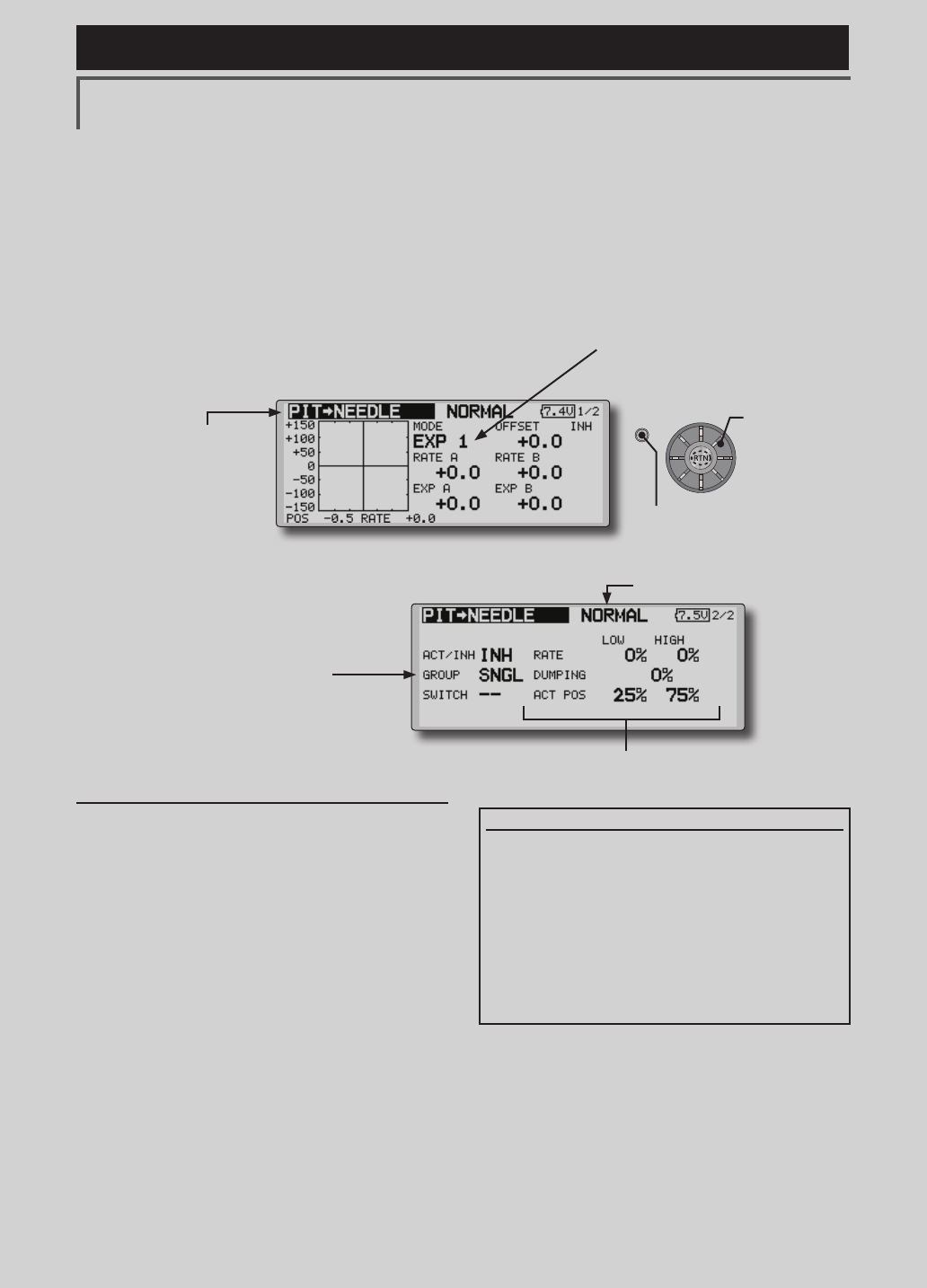
159
<Functions of Model Menu (Helicopter Functions) >
Reference FMT-03 is equipped with a stick of multi-copter exclusive use. Therefore it's
unsuitable for use of an airplane, a glider and a helicopter.
S1
●Selectthefunction
nameandreturntothe
precedingscreenby
pushingtheRTNbutton
orpushingtheHome/Exit
button.
<Editdial>
PIT to NEEDLE MIXING
This mixing is used when the engine is equipped
with needle control or other fuel-air mixture
adjustment. A needle curve can be set.
An acceleration function which temporarily
increases needle operation at throttle stick
Setting method
●Whenusingthisfunction,movethecursorto
the[ACT]itemandpushtheRTNbuttonto
switchtothedatainputmode.Turntheedit
dialtotheleftandpushtheRTNbutton.(ON
isdisplayed.)
●Whenyouwanttosetthesamecontentsat
otherconditions,selectthegroupmode.
Whenyouwanttosettheselectedcondition
only,selectthesinglemode(initialsetting).
● Aneedlecurvecanbeset.
● Aswitchcanbeset.
When[--]isset,themixing functionis
operatedbymerelyselectingthecondition.
Whensettingan[ON]/[OFF]switch,move
thecursortothe[--]itemandpushtheRTN
buttontoswitchtothedatainputmode.
PushtheRTNbuttontocalltheselection
screenandsettheswitchanditsONposition.
< Acceleration function setting>
●Accelerationcanbesetatbothsetting
atacceleration(high)andsettingat
deceleration(low).
●Theaccelerationrate(rate)andthereturn
timeafteroperation(dumping)canbeset.
●Anoperationpoint(actpos)atacceleration
anddecelerationcanbeset.When
anoperationpointwasexceeded,
accelerationoperationisperformed.
●Normally,use[POINT]type.
●Select[PITtoNEEDLE]atthemodelmenuand
callthesetupscreenshownbelowbypushing
theRTNbutton.
(Currently selected condition name)
acceleration/deceleration operation can be set.
The rise characteristic of the needle servo at
acceleration and deceleration operation can be
adjusted.
●Group/singlemodeswitching
(For more information, refer to the description at
the back of this manual.)
●Mixingcurvesetting
*For a description of the curve setting method, see the
description at the back of this manual.
●Accelerationsettings
Scrolling
●Movingcursor
●Selectingmode
●Adjustingvalue
●PushtheS1button
tocallnextpage.
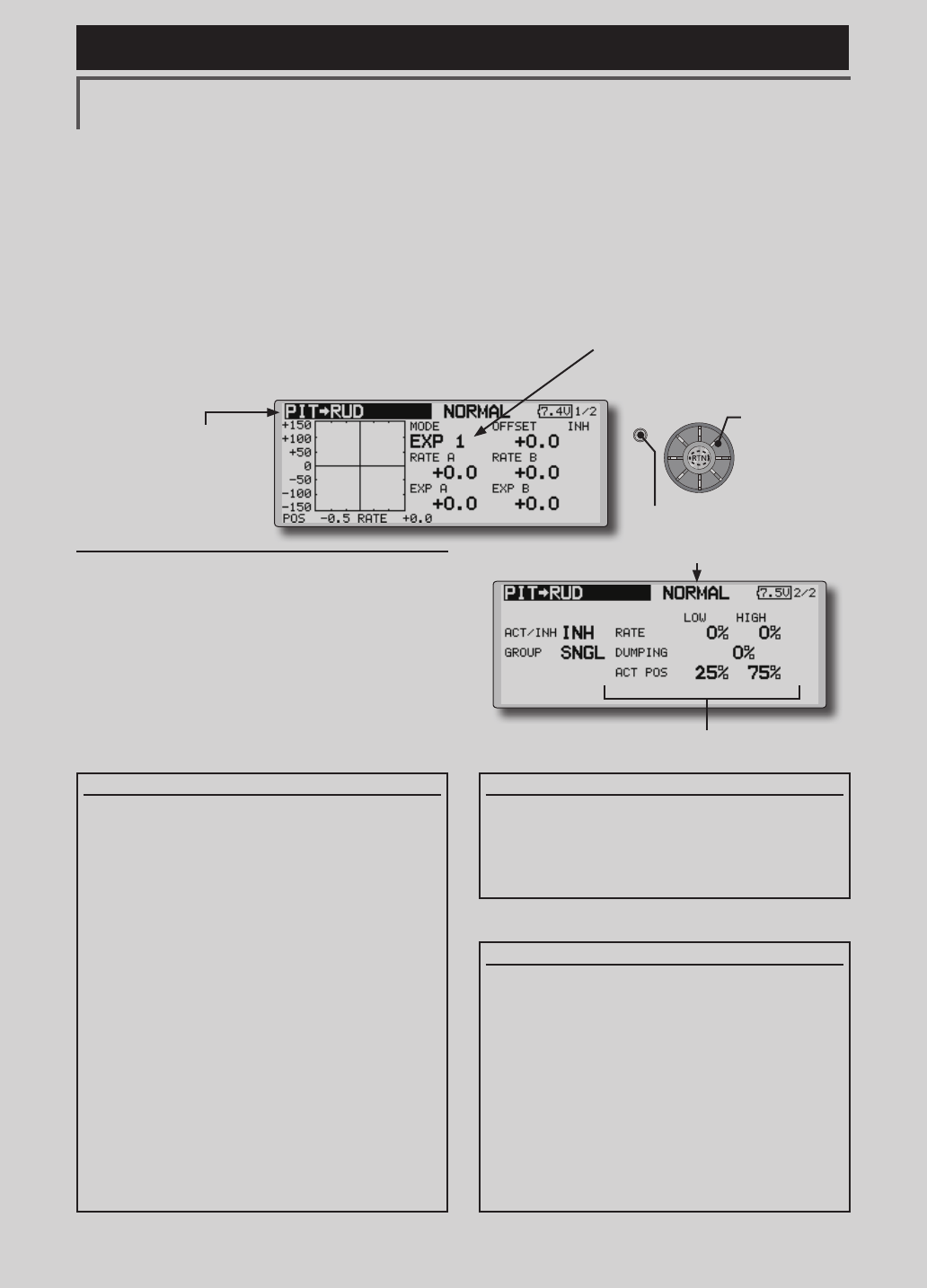
160 <Functions of Model Menu (Helicopter Functions) >
Reference FMT-03 is equipped with a stick of multi-copter exclusive use. Therefore it's
unsuitable for use of an airplane, a glider and a helicopter.
S1
●Selectthefunction
nameandreturntothe
precedingscreenby
pushingtheRTNbutton
orpushingtheHome/Exit
button.
<Editdial>
PIT to RUD MIXING (REVOLUTION MIXING)
Use this mix when you want to suppress the
reaction torque generated by main rotor pitch and
speed changes during pitch operation. Adjust so
that the nose does not move in the rudder direction.
An acceleration function which temporarily
increases the correction rate at throttle stick
acceleration/deceleration operation can be set. The
mixing rate at acceleration/deceleration can be set.
Setting method
●Whenusingthisfunction,movethecursorto
the[ACT]itemandpushtheRTNbuttonto
switchtothedatainputmode.Turntheedit
dialtotheleftandpushtheRTNbutton.(ON
isdisplayed.)
●Whenyouwanttosetthesamecontentsat
otherconditions,selectthegroupmode.
Whenyouwanttosettheselectedcondition
only,selectthesinglemode(initialsetting).
●Amixingcurveisset.
<Normal condition mixing curve>
Themixingcurveratestartsfromasmall
value.
Forarotorwithaclockwiseoperation
direction(polarity),whenpitchwas
operatedattheplusside,setsothatmixing
isintheclockwisedirection.First,trimat
hoveringandthenadjusttheneutral
position.
1.Adjustmentbetweenslowandhovering
Repeatedlyhoverfromtakeoffandland
fromhoveringataconstantratematched
toyourownrhythm,andadjustthepitchso
thenosedoesnotdeectwhenthethrottle
israisedandlowered.
2.Throttlehighside(climbinganddivingfrom
hovering)
Repeatclimbinganddivingfromhovering
ataconstantratematchedtoyourown
rhythmandadjustthepitchsothatthenose
doesnotdeflectwhenthethrottleisraised
andlowered.
However, when a GY Series or other heading
hold gyro is used, since correction is performed
by the gyro, this mix is not used. If this function
is used when the gyro operation mode is the
AVCS mode, the neutral position will change.
<Idle up condition mixing curve>
Setthemixing ratesothattherudderdirection
athigh-speedightisstraightahead.Adjust for
eachconditionused.
<Acceleration function setting>
●Accelerationoperationcanbeperformed
forbothsettingatacceleration(high)and
settingatdeceleration(low).
●Accelerationratesetting(rate)
●Thereturntimeafteroperation(dumping)
canbeset.
●Anoperationpoint(actpos)at
accelerationanddecelerationcanbeset
independently.Whenanoperationpoint
wasexceeded,accelerationoperationis
performed.
●Normally,use[POINT]type.
●Select[PITtoRUD]atthemodelmenu
andcallthesetupscreenshownbelowby
pushingtheRTNbutton.
(Currently selected condition name)
●Accelerationsettings
Scrolling
●Movingcursor
●Selectingmode
●Adjustingvalue
●PushtheS1button
tocallnextpage.
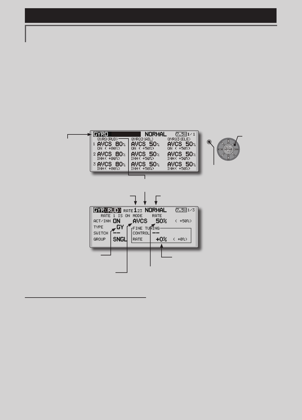
161
<Functions of Model Menu (Helicopter Functions) >
Reference FMT-03 is equipped with a stick of multi-copter exclusive use. Therefore it's
unsuitable for use of an airplane, a glider and a helicopter.
S1
●Selectthefunction
nameandreturntothe
precedingscreenby
pushingtheRTNbutton
orpushingtheHome/Exit
button.
<Editdial>
GYRO PROGRAMMING / GAIN SENSITIVITY
This function used to adjust gyro sensitivity.
The sensitivity and operation mode (Normal mode/
AVCS mode) can be set for each condition.
The gyro sensitivity can be switched with each
condition or the switch. (5 sensitivities)
*Compatible with 3 axis gyro (CGY750).
Setting method
● Whenusingthisfunction,movethecursorto
the[ACT]itemandpushtheRTNbuttonto
switchtothedatainputmode.Turntheedit
dialtotheleftandpushtheRTNbutton.(ON
isdisplayed.)
● Whenyouwanttosetthesamecontentsat
otherconditions,selectthegroupmode.
Whenyouwanttosettheselectedcondition
only,selectthesinglemode(initialsetting).
● Threerates canbeswitched foreach
condition.(Rate1/Rate2/Rate3)
● AnetuningVRcanbeset.
●Select[GYRO]atthemodelmenuand
callthesetupscreenshownbelowby
pushingtheRTNbutton.
(Currently selected condition name)(Rate No. display)
●FinetuningVRsettings
●Gyrosensitivityadjustment
●Modeselection:
[AVCS]/[NORM]
●Gyrotypeselection:
[GY]/[NORM]
Note:Whenusingthe[Gyro2]/[Gyro3]function,
assign[Gyro2]/[Gyro3]toanychannelon
thefunctionscreen.
Alwayssetto[--]both(control)and(trim)for
the[Gyro]functionattheFunctionmenuin
theLinkagemenu.
●WhentheGYROfunctionbuttonisselected,
eachGYROdetailedsettingscreenappears.
Scrolling
●Movingcursor
●Selectingmode
●Adjustingvalue
●PushtheS1button
tocallnextpage.
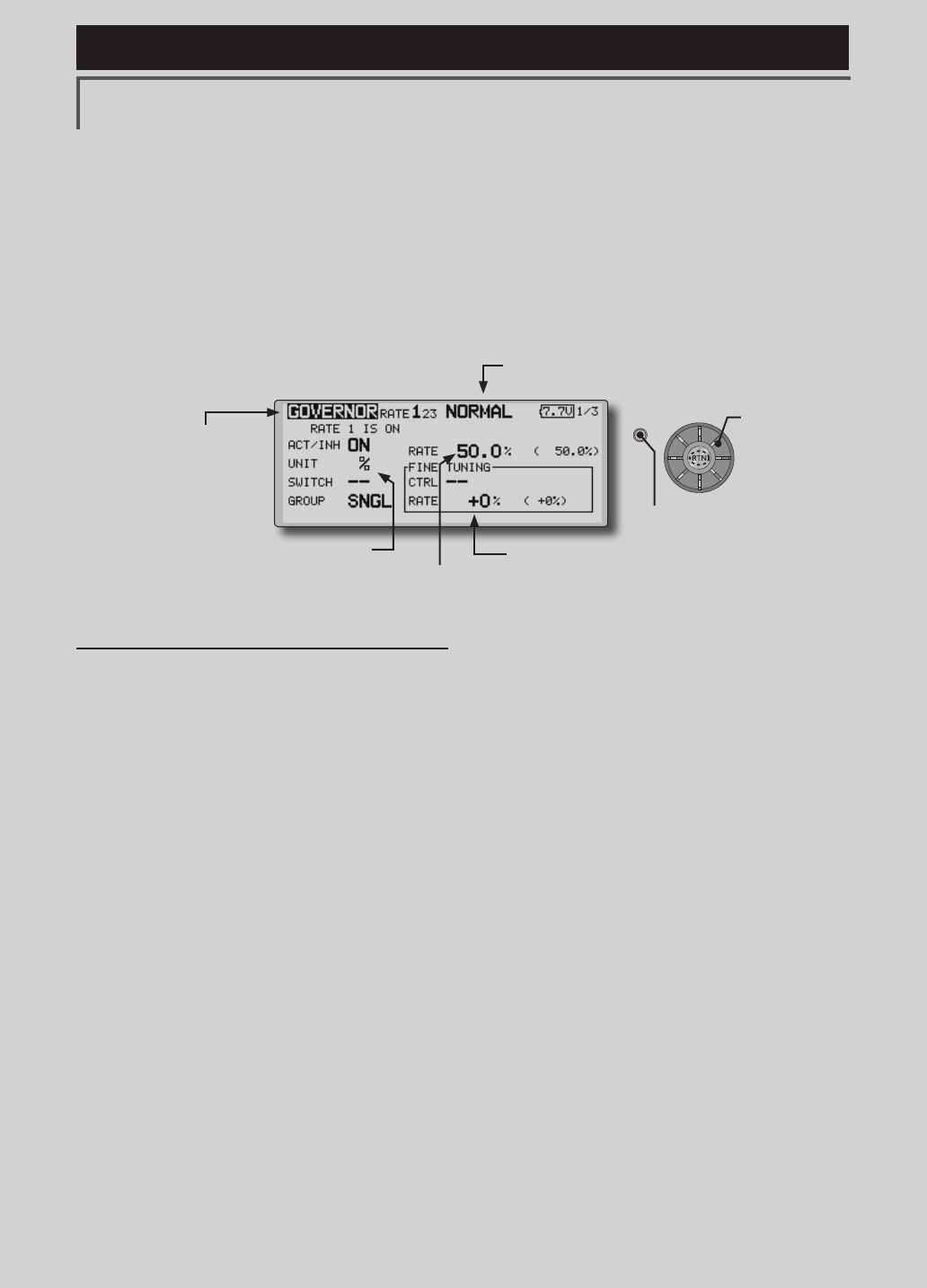
162 <Functions of Model Menu (Helicopter Functions) >
Reference FMT-03 is equipped with a stick of multi-copter exclusive use. Therefore it's
unsuitable for use of an airplane, a glider and a helicopter.
S1
●Selectthefunction
nameandreturntothe
precedingscreenby
pushingtheRTNbutton
orpushingtheHome/Exit
button.
<Editdial>
GOVERNOR PROGRAMMING
When using a Futaba governor, this function is
used to switch the RPM of the helicopters head. Up
to 3 rates can be set for each condition.
*The governor is used by connecting the governor speed
setting channel to CH7 (initial setting).
*When using an independent governor [ON]/[OFF] switch,
connect the AUX([ON]/[OFF]) connector of the governor to
CH8 (initial setting) and set the switch to CH8 (Governor2)
at the Function menu of the Linkage Menu.
*When using the Fuel Mixture function, the mixture servo
is controlled from the governor. When transmitting the
mixture curve data from the transmitter to the governor, the
governor AUX (m.trm) connector must be connected to CH8
(initial setting) and governor side setting performed. See the
governor instruction manual.
Note:Alwaysset(Control)and(Trim)to[--]for
[Governor]and[Governor2]oftheFunctionmenu
oftheLinkagemenu.
●Select[GOVERNOR]atthemodelmenu
andcallthesetupscreenshownbelowby
pushingtheRTNbutton.
(Currently selected condition name)
●FinetuningVRsettings
●RPMadjustment
●Unitdisplayselection:
[%]/[rpm]
Setting method
●Activate the mixing
Whenusingthisfunction,movethecursorto
the[INH]itemandpushtheRTNbuttonto
switchtothedatainputmode.
SelecttheACTmodebyscrollingtheedit
dial.
*The display blinks.
PushtheRTNbuttontoactivatethemixing
andreturntothecursormode.(ONis
displayed.)
WhentheGovernorischangedfromthe
defaultinhibited(INH)statetotheactive
(ACT)state,theendpointmenuwillbe
displayedanditispossibletoutilizethe
endpointsforthisgivencondition.
*When the function is set ON/OFF at the governor setup
screen, the governor rpm setting channel end point servo
travel and limit point are now initialized.
*When changed from INH to ACT (ON), the servo travel is
initialized to 100 and the limit point is initialized to 155.
*When operation is changed to INH at all conditions, the
servo travel is initialized to 100 and the limit point is
initialized to 135.
●RPM adjustment
Movethecursortotherateitemandpush
theRTNbuttontoswitchtothedatainput
mode.
Adjusttherpmbyscrollingtheeditdial.
Initialvalue:50%(1500rpm)
Adjustmentrange:OFF,0~110%(OFF,
700~3500rpm)
*When the RTN button is pushed for one second, the
sensitivity is reset to the initial value.)
PushtheRTNbuttontoreturntothecursor
mode.
●Unit diplay selection
MovethecursortotheUNITitemandpush
theRTNbuttontoswitchtothedatainput
mode.Selecttheunitbyscrollingtheedit
dial.
PushtheRTNbuttontochangetheoperation
modeandreturntothecursormode.
Scrolling
●Movingcursor
●Selectingmode
●Adjustingvalue
●PushtheS1button
tocallnextpage.
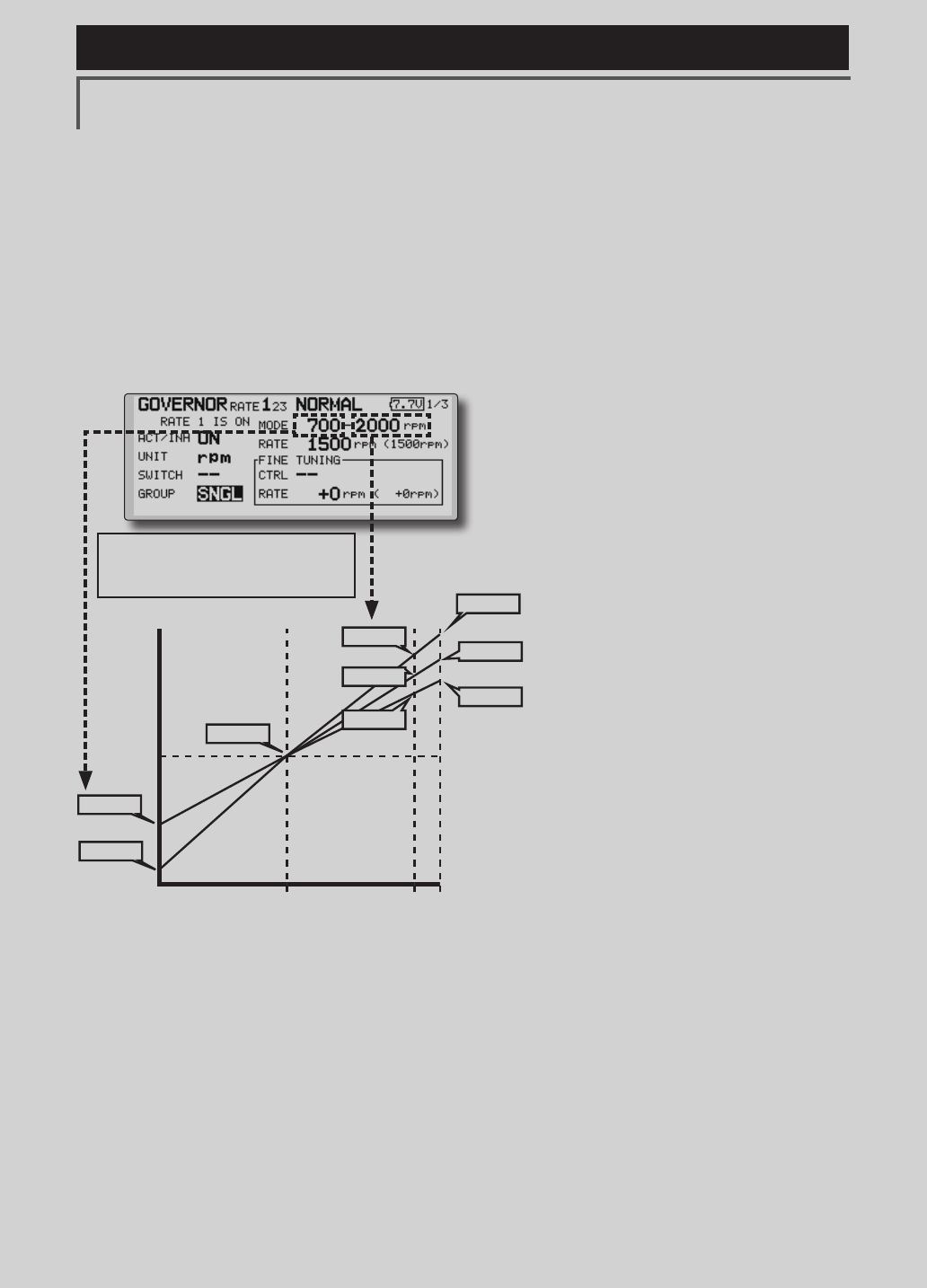
163
<Functions of Model Menu (Helicopter Functions) >
Reference FMT-03 is equipped with a stick of multi-copter exclusive use. Therefore it's
unsuitable for use of an airplane, a glider and a helicopter.
●Diplay mode selection
*When [rpm] mode is selected above setting, the display
mode can be selected.
* There is no change in the transmitter output even when the
"MODE" is changed. Calibration should be performed via
the governor.
* In order to use the Governor function of the FMT-03, it is
necessary to change the settings on the governor for the low
side 700 rpm mode.
WhentheMODEoftheGovernorscreen's
modelmenuischanged,thechangeisalso
indicatedon-screen.
The chart below indicates the
mode percentage and the
corresponding RPM.
●Fine tuning VR settings
Movethecursortothe[--]itemandpushthe
RTNbuttontoaccesstheselectionscreen.
Selectthecontrol.
*For a description of the switch selection method, see the
description at the back of this manual.
Movethecursortotherateitemandpush
theRTNbuttontoswitchtothedatainput
mode.
Adjustthetrimratebyscrollingtheeditdial.
Initialvalue:0%(0rpm)
main rotor R.P.M.
3900rpm
2700rpm
2100rpm
0% 100% 110%
main rotor R.P.M. setting channel travel
50% : neutral
2500rpm
2000rpm
1500rpm
1000rpm
700rpm
3500rpm
Adjustmentrange:-20~+20%(-800~+800rpm)
*When the RTN button is pushed for one second, the
sensitivity is reset to the initial value.)
PushtheRTNbuttontoreturntothecursor
mode.

164 <Functions of Model Menu (Helicopter Functions) >
Reference FMT-03 is equipped with a stick of multi-copter exclusive use. Therefore it's
unsuitable for use of an airplane, a glider and a helicopter.
COND.HOLD Conditionholdfunction
This function may be used to x the maximum
speed of the engine so that you may adjust flight
conditions when the engine is running. An alarm
indicates that the function is operating. It will
prevent the engine from increasing when adjusting
the idle-up settings.
While this function is active, the throttle servo
position is fixed at the point set from when the
function is activated. You must deactivate this
function when you are through making adjustments.
The system will not allow you to activate/
deactivate this function in either of the following
states:
• Whenanyoftheflightconditionswitches
areon.
• Whenthethrottlestickishigherthanthe
1/3point.
To activate/deactivate condition hold:
(Home screen)
1.Movethecursorto[CNDHOLD].
2.Setthethrottlesticklowerthanthe1/3point.
3.PushtheRTNbuttontoactivatethecondition
holdfunction.
*When this function is active, "IS ON" appears at the right of
the [CND HOLD] display at the left bottom of the screen.
(LINKAGE menu/MODEL menu)
1.Movethecursorto[COND.HOLD].
2.Setthethrottlesticklowerthanthe1/3point.
3.PushtheRTNbuttontoactivatethecondition
holdfunction.
*Operation is displayed at the bottom of the menu.
Function ON: "CND HOLD IS ON" is displayed.
Function OFF: "CND HOLD IS OFF" is displayed.
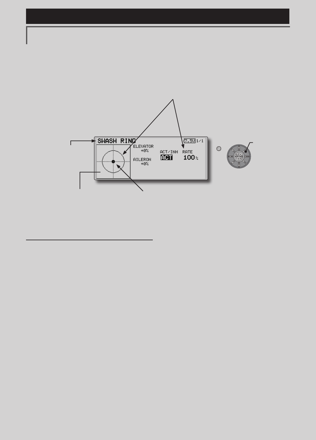
165
<Functions of Model Menu (Helicopter Functions) >
Reference FMT-03 is equipped with a stick of multi-copter exclusive use. Therefore it's
unsuitable for use of an airplane, a glider and a helicopter.
S1
●Selectthefunction
nameandreturntothe
precedingscreenby
pushingtheRTNbutton
orpushingtheHome/Exit
button.
<Editdial>
SWASH RING
Swash ring setting procedure
*Perform the following settings after using the edit dial to
move the cursor to the item you want to set.
1.Activatethefunction:
Movethecursortothe[ACT/INH]itemand
pushtheRTNbuttontoswitchtothedata
inputmode.
Switchtheblinkingfrom"INH"to"ACT"by
turningtheeditdialtotheleftandthenpush
theRTNbutton.
2.Ratesetting:
Usetheeditdialtomovethecursortothe
[RATE]itempushtheRTNbuttontoswitchto
thedatainputmode.
Usetheeditdialtosettherate.
Initialvalue:100%.
Adjustmentrange:50%to200%.
*Adjust the rate to maximum swash tilt.
(When the RTN button is pushed for 1 second, the rate is
reset to the initial value.)
PushtheRTNbuttontoendadjustmentand
returntothecursormovemode.
Limitstheswashplatetraveltowithinaxedrange.(Helicopteronly)
This function limits the swash travel to within
a fixed range to prevent damaging of the swash
linkage by simultaneous operation of the ailerons
and elevators. It is effective in 3D aerobatics which
use a large travel.
● Theoperatingrangedisplayarea:
Theverticaldirectionshowstheelevatortravel.
Thehorizontaldirectionshowstheaileron
travel.
●Themarkershowsthestick
position.
●Select[SWASHRING]atthelinkage
menuandcallthesetupscreenshown
belowbypushingtheRTNbutton.
●Whentheswashringfunctionisactivated,a
circleisdisplayedintheoperatingrangedisplay
areaandtherateinputboxisdisplayed.Stick
operationislimitedtowithintheareaofthiscircle.
Scrolling
●Movingcursor
●Selectingmode
●Adjustingvalue
<Linkage Menu >
<Functions of Linkage Menu (Helicopter Functions) >

166 <Functions of Model Menu (Helicopter Functions) >
Reference FMT-03 is equipped with a stick of multi-copter exclusive use. Therefore it's
unsuitable for use of an airplane, a glider and a helicopter.
S1
●Selectthefunction
nameandreturntothe
precedingscreenby
pushingtheRTNbutton
orpushingtheHome/Exit
button.
<Editdial>
SWASH Swashoperationlinkagecorrectionfunction.(helicopteronly,except
swashtypeH-1)
Neutral Point
At your linkages, if the servo horn deviates from
a perpendicular position at neutral, the linkage
compensation functions in this menu may not
compensate effectively. To correct this use the
neutral point function. This will move the neutral
point of the servos to the actual perpendicular
position. However, this adjustment changes only
the axis point of the compensation functions in this
menu, and does not affect the neutral position of
other functions.
Swash AFR
Swash AFR function reduces/increases/reverses
the rate (travel) of the aileron, elevator and
collective pitch functions, by adjusting or reversing
the motion of all servos involved in that function,
only when using that function.
*Before making the following settings, use the edit dial to
move the cursor to the item you want to set.
Neutral point setting procedure
The neutral point becomes the correction
standard point.
*Adjusting the servo horn so that the neutral point is near the
50% position makes the mixing amount small.
1.Neutralpointsetting
Movethecursortothe[POINT]itemandhold
thepitchoperationsothattheservohornis
atarightangletothelinkagerodandpush
theRTNbuttonfor1secondandreadthe
neutralposition.
*The neutral point can also be displayed by bar graph.
Afterreadingtheneutralpoint,usethe
othercorrectionfunctionstomakefurther
adjustments.
Mixing Rate
This compensation mixing is used to correct
the tendency of the swash-plate for each control.
The following compensation mixing is possible;
PIT to AIL, PIT to ELE, AIL to PIT, ELE to AIL,
and ELE to PIT (HR3 mode.) It adjusts the swash-
plate to operate correctly for each control using the
corresponding compensation mixing.
Linkage Compensation
This compensation mixing is used to correct the
tendency of the swash-plate for pitch control at low
pitch and high pitch.
Speed Compensation
This function is used to cancel the reaction that is
generated by the difference of the operation amount
of each servo when the swash-plate moves.
Swash AFR setting procedure
The swash AFR function makes adjustments
so that the servos travel the specified amount
by [AILERON], [ELEVATOR], and [PITCH]
operation.
1.Usetheeditdialtomovethecursortothe
functionyouwanttoadjustandpushthe
RTNbuttontoswitchtothedatainputmode.
2.AdjusttheAFRratebyturningtheeditdialto
theleftorright.
Initialvalue:+50%
Adjustmentrange:-100%~+100%
(When the RTN button is pushed for 1 second, the AFR rate
is reset to the initial value.)
PushtheRTNbuttontoendadjustmentand
returntothecursormovemode.
●Select[SWASH]atthelinkagemenuandcallthesetup
screenshownbelowbypushingtheRTNbutton.
Scrolling
●Movingcursor
●Selectingmode
●Adjustingvalue
<Functions of Linkage Menu (Helicopter Functions) >
<Linkage Menu >
●PushtheS1button
tocallnextpage.

167
<Functions of Model Menu (Helicopter Functions) >
Reference FMT-03 is equipped with a stick of multi-copter exclusive use. Therefore it's
unsuitable for use of an airplane, a glider and a helicopter.
Mixing rate setting procedure
The HR-3 is taken as an example to describe
mixing rate setting. Mixing applied in other swash
modes is different, but the setting procedure is the
same.
*Set the throttle stick to the preset neutral point. Adjust the
length of the linkage rod so that the swash plate is horizontal
at this position.
*The sub trim function can be used to make small
adjustments.
*Adjust so that the pitch curve is a straight line and pitch
operation is maximum.
*When making the following setting, use the edit dial to
move the cursor to the item you want to set and push the
RTN button to switch to the data input mode. Push the RTN
button to end adjustment and return to the cursor move
mode.
1.Adjustmentataileronoperation[AILtoPIT]
AdjusttheAILtoPITratesothereisno
interferenceintheelevatororpitchdirection
whentheaileronstickismovedtotheleft
andright.
*Adjust by turning the edit dial to the left or right.
*The left and right sides can be adjusted individually.
2.Adjustmentatelevatoroperation[ELEto
AIL]/[ELEtoPIT]
AdjusttheELEtoAILandELEtoPITratesso
thereisnointerferenceintheaileronorpitch
directionwhentheelevatorstickismoved
upanddown.
*Adjust by turning the edit dial to the left and right.
*The up and down sides can be adjusted individually.
3.Adjustmentatpitchoperation[PITtoAIL][PIT
toELE]
AdjustthePITtoAILandPITtoELEratesso
thattheswashplatemovestothehorizontal
positionwhenthethrottlestickwasmovedto
maximumslowandfullhigh.
*Adjust by turning the edit dial to the left and right.
*The slow and high sides can be adjusted individually.
Linkage compensation setting procedure
*Perform linkage compensation setting after mixing rate
setting.
*Linkage compensation compensates for interference by
aileron operation with the elevator or elevator operation
with the aileron at collective pitch control for low pitch and
high pitch.
*When making the following setting, use the edit dial to
move the cursor to the item you want to set and push the
RTN button to switch to the data input mode. Push the RTN
button to end adjustment and return to the cursor move
mode.
1.Compensationataileronoperation
[AILERON]
Setthethrottletothemaximumslowposition.
Movetheaileronsticktotheleftandright
andadjusttheaileroncompensationamount
sothatinterferenceintheelevatororpitch
directionatthattimeisminimum.
*Adjust the edit dial to the left and right.
*The left and right sides can be adjusted individually.
*When the interference increases when the compensation
amount was increased, make adjustments with the
compensation direction [DIR] as "-".
2.Compensationatelevatoroperation
[ELEVATOR]
Adjusttheelevatorcompensationamount
sothattheaileronorpitchdirection
interferencewhentheelevatorstickwas
movedupanddownisminimum.
3.Regardingsteps1and2above,perform
aileronandelevatorcompensationsimilarly
atthefullhighsideofthethrottlestickalso.
Speed compensation setting procedure
1.Usetheeditdialtomovethecursortothe
"SPEEDCOMPENSATION"itemandpushthe
RTNbuttontoswitchtothedatainputmode.
2.Setthethrottlesticktotheneutralpoint
position.Quicklymovetheelevatorstickand
adjustthespeedcompensationamount
[SPEEDCOMPENSATION]forminimum
interferenceinthepitchdirection.
*Adjust by turning the edit dial to the left and right.
PushtheRTNbuttontoendadjustmentand
returntothecursormovemode.
<Functions of Linkage Menu (Helicopter Functions) >

168 <Functions of Model Menu (Helicopter Functions) >
Reference FMT-03 is equipped with a stick of multi-copter exclusive use. Therefore it's
unsuitable for use of an airplane, a glider and a helicopter.
FUTABA CORPORATION Phone: +81 475 32 6381
1080 Yabutsuka, Chosei-mura, Chosei-gun, Chiba-ken, 299-4395, Japan
©FUTABA CORPORATION 2017, 03 (1)