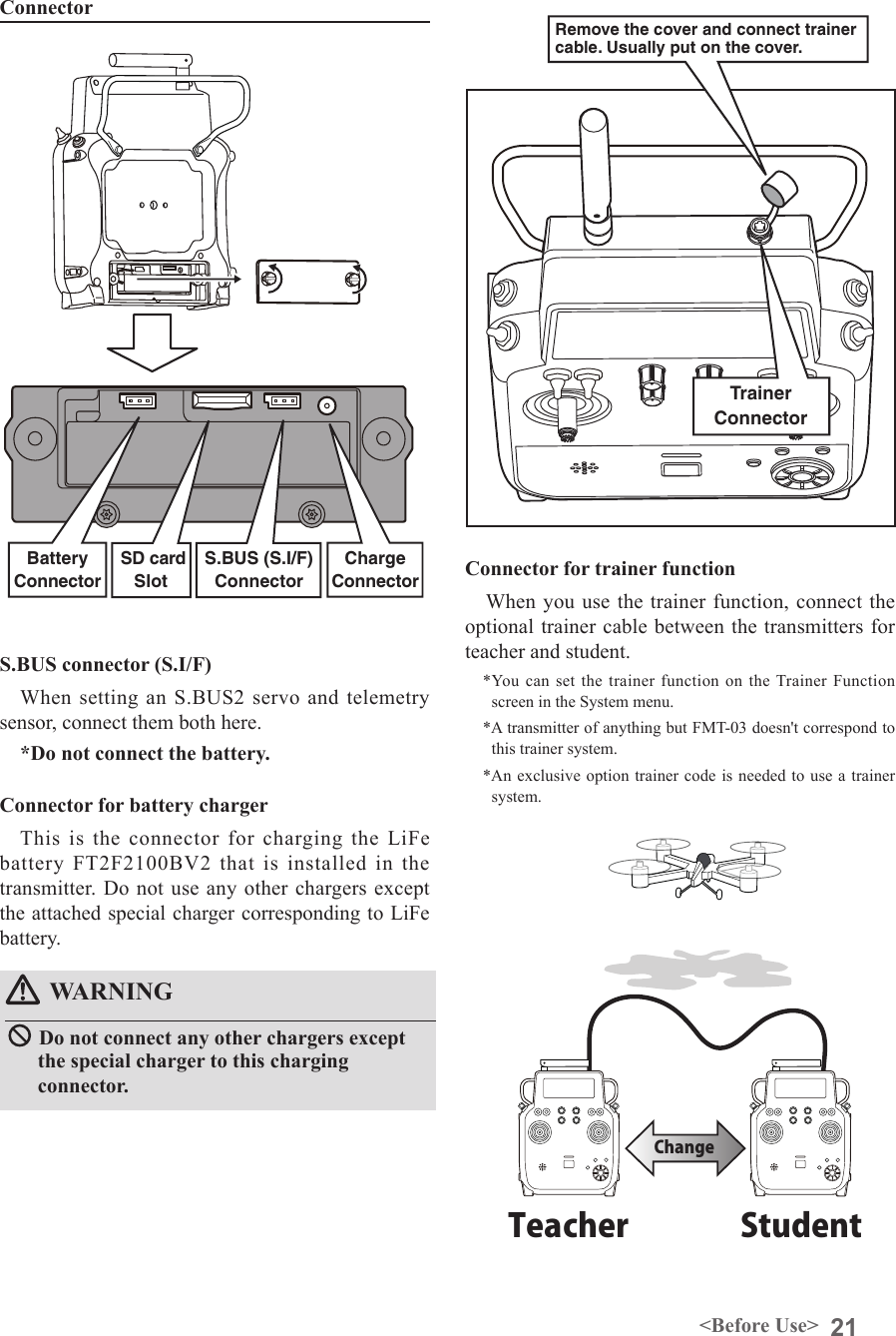
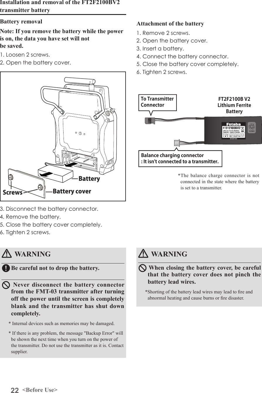
Futaba FMT-03-24G Radio Control User Manual Part I Rev 01 170210
Futaba Corporation Radio Control Part I Rev 01 170210
UserManual.wiki
>
Futaba
>
FMT-03-24G User Manual
>
User Manual-Part I-Rev.01(170210)
Contents
1.
User Manual-Part I-Rev.01(170210)
2.
User Manual-Part II
User Manual-Part I-Rev.01(170210)
Navigation menu
Upload a User Manual
Namespaces
Wiki Guide
HTML
PDF
Info
Views
User Manual
Discussion / Help
Navigation
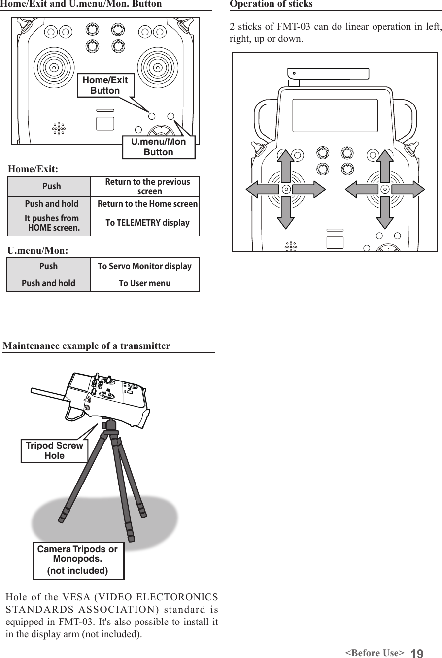
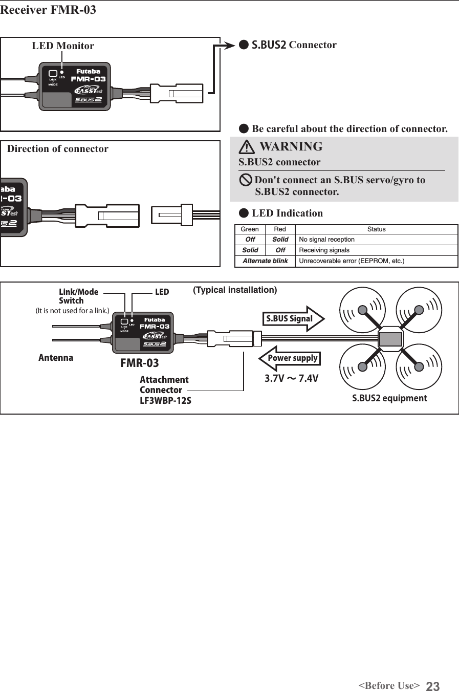
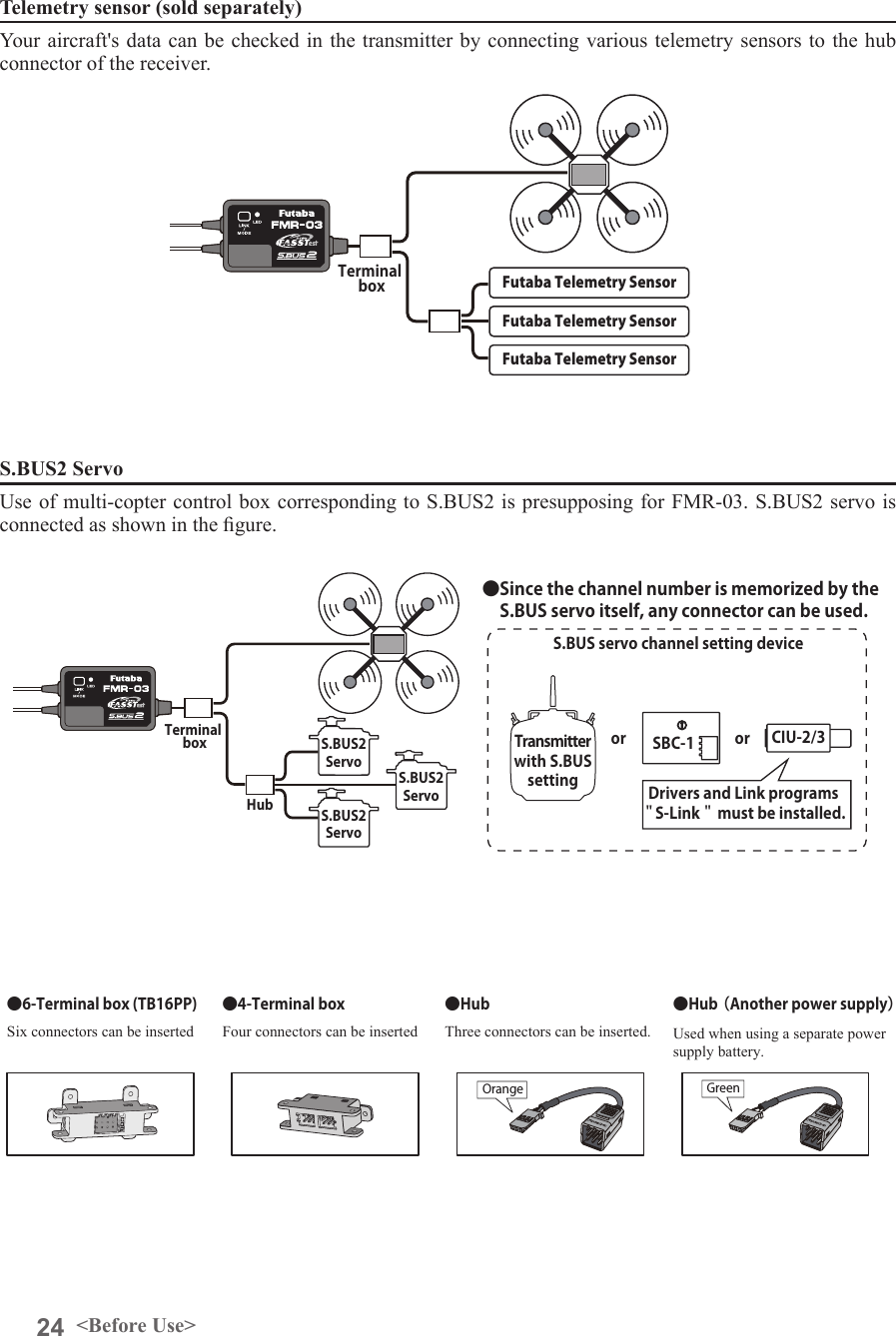
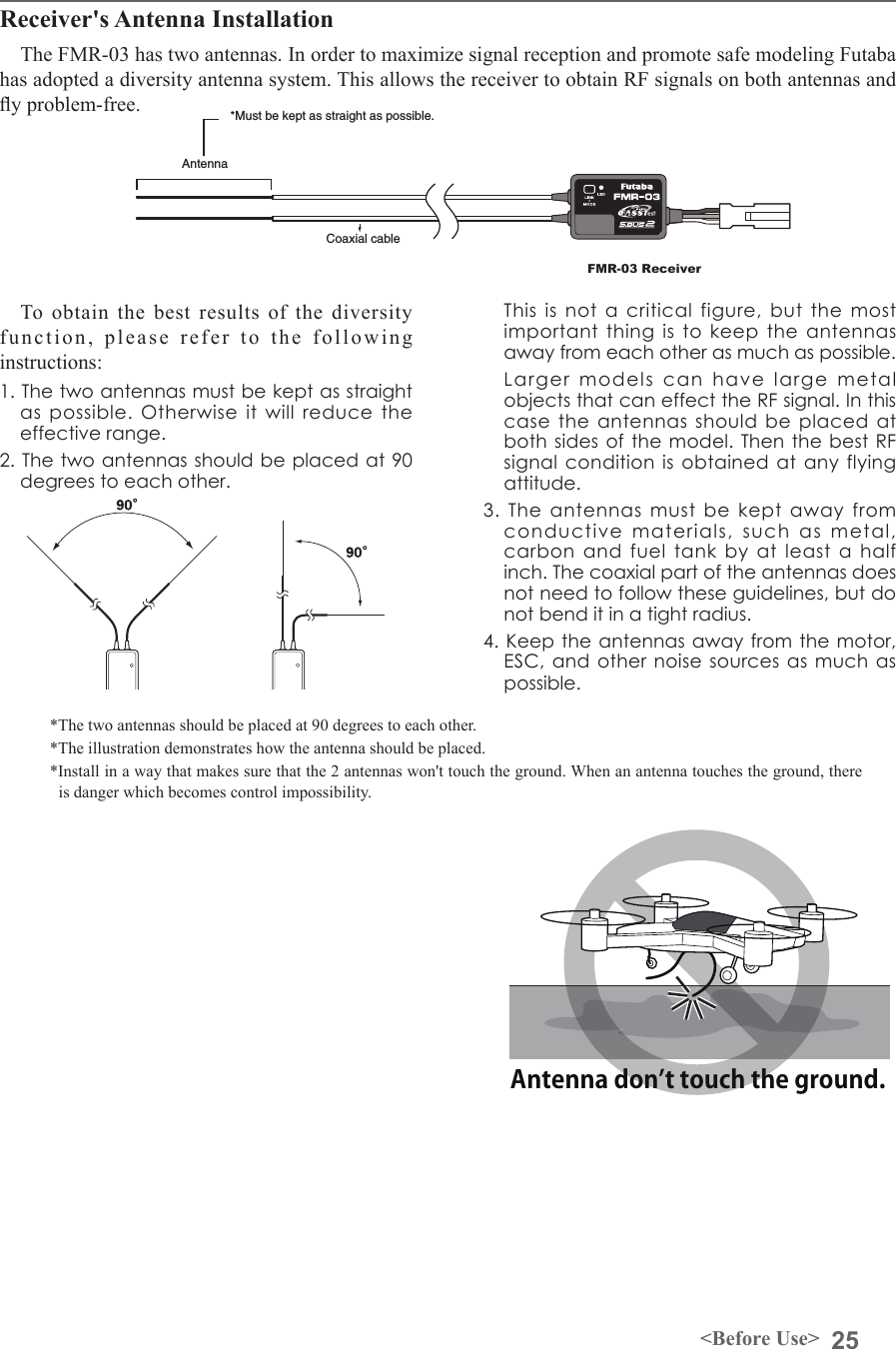
![INTRODUCTION............................................... 4●Support and Service ......................................... 4●Application, Export, and Modication ........... 4●Denitions of Symbols ...................................... 7●Safety Precautions (do not operate without reading) ............................................................. 7BEFORE USE ................................................... 11●Features of FMT-03 ....................................... 11●Contents and technical specications ........... 12●Accessories ....................................................... 13●Transmitter controls ....................................... 14Transmitter's antenna .................................... 15Switch (SA-SH) ............................................... 17Volume (DA-DD) ............................................ 17Monitor LED .................................................. 17Edit dial ........................................................... 17Home/Exit, U.menu/Mon. Button ................. 19Maintenance example of a transmitter ........ 19Micro SD Card ............................................... 20Connector ........................................................ 21Installation and removal of the battery ........ 22●Receiver FMR-03 ............................................ 23●Telemetry sensor ............................................. 24●S.BUS2 servo ................................................... 24●Receiver's antenna installation ...................... 25●Mounting the servo ......................................... 26●Safety precautions when installing servos ... 26●S.BUS2 Devicesetting ..................................... 27BASIC OPERATION ....................................... 28●Battery Charging ............................................ 28●How to turn transmitter power ON/OFF .... 29●Registration of the user's name ..................... 29●Home screen .................................................... 30●User menu ........................................................ 31●Key lock ........................................................... 32●Link procedure .............................................. 33●Range testing your R/C system...................... 35●Channels connection by multicopter type .... 36FUNCTIONS OF SYSTEM MENU ................ 37Display ............................................................. 38System Timer .................................................. 39User Name ....................................................... 40Sound ............................................................... 41H/W Setting ..................................................... 42Information .................................................... 44Range Check .................................................. 45S.BUS Servo ................................................... 46FUNCTIONS OF LINKAGE MENU ............. 49Linkage Menu functions table ...................... 49Servo Monitor ................................................. 50Model Select .................................................... 51Model Type (This function isn't used) .......... 53System Type .................................................... 54Function .......................................................... 56Sub-Trim ......................................................... 58Servo Reverse ................................................. 59Fail Safe ........................................................... 60End Point ........................................................ 61Throttle Cut ................................................... 62Idle Down ....................................................... 63Timer ............................................................... 64T1-T6 Setting .................................................. 66Multiprop ........................................................ 67Function Name ............................................... 68Telemetry......................................................... 69Telemetry:receiver [battery] ......................... 70Telemetry:receiver [EXT-batt] ...................... 71Telemetry:temperature .................................. 72Telemetry:rpm sensor .................................... 73Telemetry:altitude .......................................... 74Telemetry:altitude [variometer] .................... 75Telemetry:voltage [battery] ........................... 76Telemetry:voltage [EXT-volt] ........................ 77TABLE OF CONTENTS](https://usermanual.wiki/Futaba/FMT-03-24G.User-Manual-Part-I-Rev-01-170210/User-Guide-3285339-Page-2.png)
![TABLE OF CONTENTSTelemetry:GPS [distance] .............................. 78Telemetry:GPS [speed] .................................. 80Telemetry:GPS [altitude,variometer,position] ..... 81Telemetry:Servo sensor [current] [temperature] [angle] ............................................................. 82Telemetry:Current sensor [current] [voltage] [capacity] ......................................................... 83Sensor .............................................................. 84Sensor:reload .................................................. 85Sensor:register ................................................ 85Sensor:change slot .......................................... 86Tele. Setting ..................................................... 87Warning ........................................................... 88Trainer ............................................................. 89Stick Alarm ..................................................... 92Data Reset ....................................................... 93FUNCTIONS OF MODEL MENU ................. 94●Common Functions ........................................ 94Condition Select ............................................. 95AFR ................................................................ 97Dual Rate ........................................................ 98Program Mix ................................................... 99Gyro ............................................................... 103DATA ................................................................ 104●Common Operations used in function setup screen ............................................................. 104●Updating ........................................................ 112Reference.......................................................... 113●Airplane/Glider Functions ........................... 114Servo connection by airplane/glider type ... 116AIL Differential ............................................ 120Flap Setting ................................................... 121AIL to Camber FLP ..................................... 122AIL to Brake FLP ......................................... 123AIL to RUD ................................................... 124Airbrake to ELE ........................................... 125RUD to AIL ................................................... 127Camber Mix .................................................. 128ELE to Camber ............................................ 130Camber FLP to ELE .................................... 131Buttery ........................................................ 132Trim Mix 1/2 ................................................. 134Airbrake (Airplane only) ............................. 136Gyro (for GYA type gyro) ............................ 138V-tail .............................................................. 140Ailevator ........................................................ 141Winglet .......................................................... 142Motor ............................................................. 143Acceleration .................................................. 144RUD to ELE .................................................. 145Snap Roll (Airplane only) ............................ 146●Helicopter Functions .................................... 147Servo connection by helicopter type ........... 148PIT Curve ..................................................... 149PIT trim ......................................................... 150THR Curve ................................................... 152Throttle hover trim ...................................... 153Acceleration .................................................. 155THR Hold ...................................................... 156Swash Mix ..................................................... 157Throttle Mix .................................................. 158PIT to Needle ................................................ 159PIT to RUD (Revolution mix) ..................... 160Gyro (for GY type gyro) .............................. 161Governor ....................................................... 162Cond. Hold .................................................... 164Swash Ring (Linkage Menu) ....................... 165Swash (Linkage Menu) ................................ 166ReferenceFMT-03 is equipped with a stick of multi-copter exclusive use. Therefore it's unsuitable for use of an airplane, a glider and a helicopter.](https://usermanual.wiki/Futaba/FMT-03-24G.User-Manual-Part-I-Rev-01-170210/User-Guide-3285339-Page-3.png)


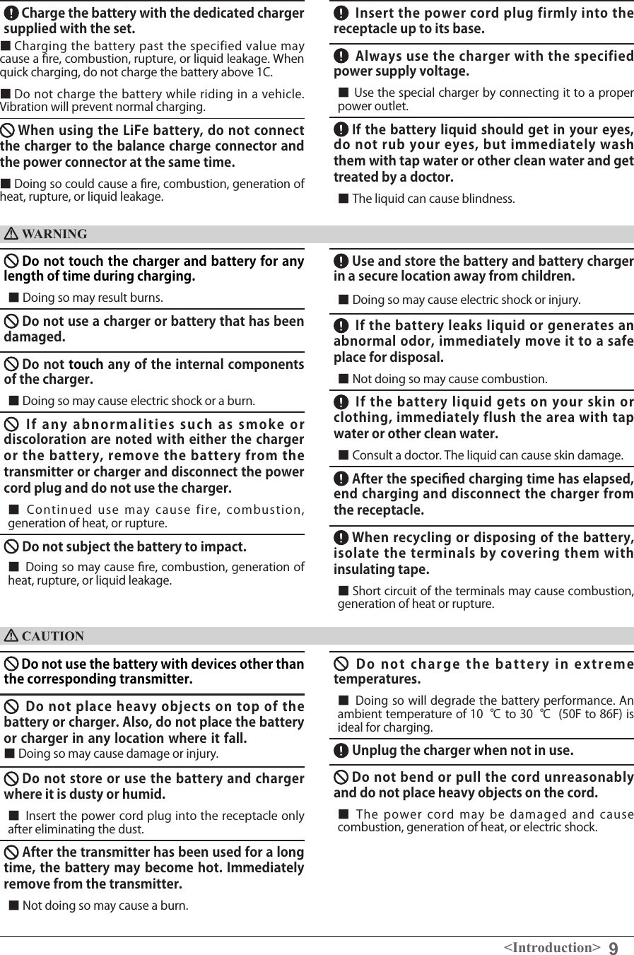
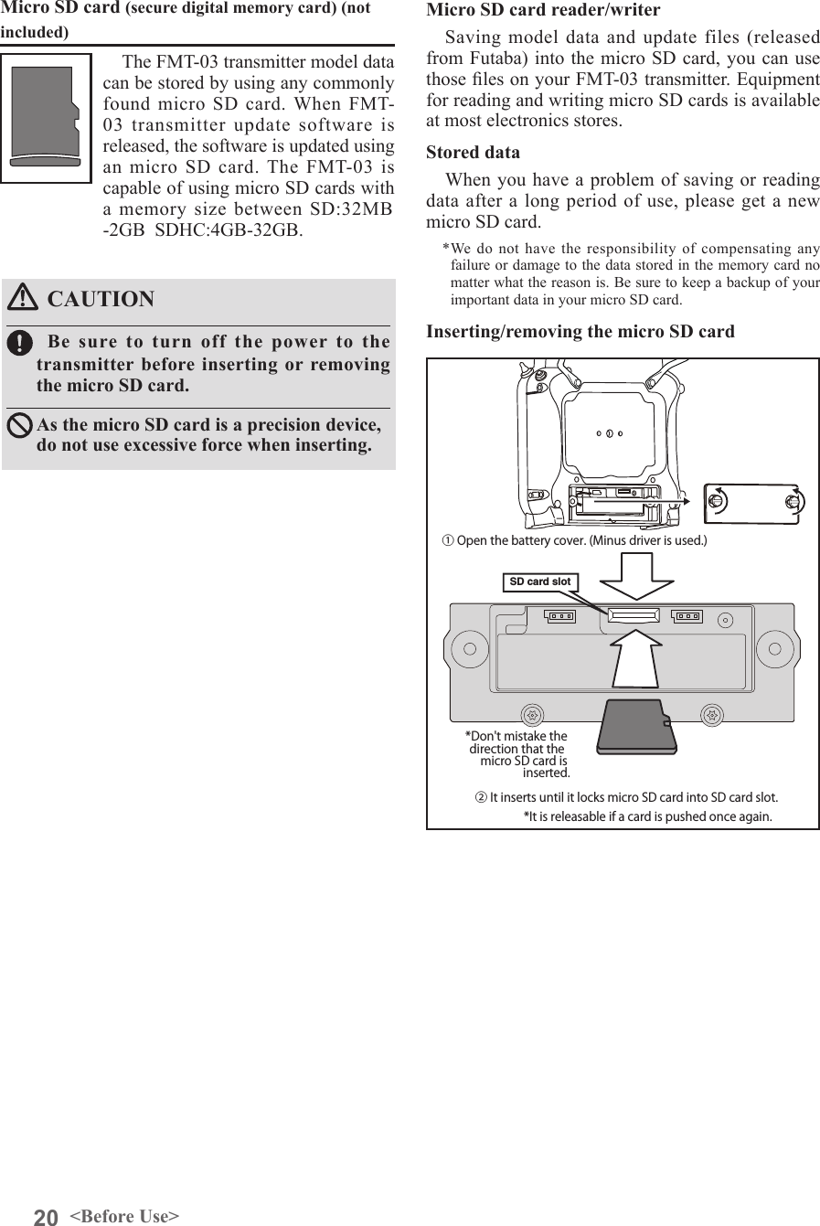
![10 <Introduction>Never disassemble or modify the micro SD Card. Do not unreasonably bend, drop, scratch or place heavy objects on the micro SD Card.Since the micro SD Card is an electronic device, be careful of static electricity. ■ Static electricity may cause erroneous operation or trouble. Do not use the micro SD Card near radio and television sets, audio equipment, motors and other equipment that generate noise. ■ Doing so may cause erroneous operation. Do not store the micro SD Card in the following places: ・ Where the humidity is high ・ Where the temperature difference is severe Micro SD Card (Commercial Product) Handling PrecautionsWARNINGCAUTION*Read the instruction manual supplied with the micro SD Card for details.●Recorded dataThe data recorded on the micro SD Card cannot be compensated regardless of the contents or cause of the trouble or obstruction. Futaba does not perform data restoration or recovery work.If smoke or an abnormal odor emanates from the card, immediately turn off the transmitter power. Do not use the Micro SD Card where it may be exposed to water, chemicals, oil, or other uids.■ Doing so may cause a fire or electric shock by short circuit. ・ Where it is very dusty ・ Where the card will be exposed to shock and vibration ・ Near speakers and other magnetic devices Do not expose the card to shock and vibration and do not remove the card from the card slot while data is being written or read. ■ The data may be damaged or lost. Keep wireless equipment, batteries, aircraft, etc. away from children. Storage and Disposal PrecautionsWARNINGDo not store wireless devices in the following places: ・ Where it is extremely hot (40 ℃ [104F] or higher) or cold (-10℃ [14F] or lower)・ Where the equipment will be exposed to direct sunlight ・ Where the humidity is high ・ Where vibration is prevalent ・ Where it is very dusty CAUTION・ Where the device may be exposed to steam and heatWhen the device will not be used for a long time, remove the battery from the transmitter and aircraft and store them in a dry place where the temperature is between 0 and 30℃ [32F and 86F]. ■ Left standing 'as is' may will cause battery deterioration, liquid leakage, etc. Do not directly expose plastic parts to fuel, oil, exhaust gas, etc. ■ If left in such an environment, the plastic may be attacked and damaged. ■ Since the metal parts of the case may corrode, always keep them clean. Always use genuine Futaba products such as transmitter, receiver, servo, FET amplifier, battery, etc. Other PrecautionsCAUTION■ Futaba is not responsible for damage sustained by combination with other than Futaba Genuine Parts. Use the parts specified in the instruction manual and catalog. This product SHOULD NOT been used for the devices that is directly related to human life and/or harmful devices for human body such as below applications.(1) Medical Devices(2) Aerospace/Aviation Related Devices(3) Nucleated Devices e.t.c.](https://usermanual.wiki/Futaba/FMT-03-24G.User-Manual-Part-I-Rev-01-170210/User-Guide-3285339-Page-10.png)
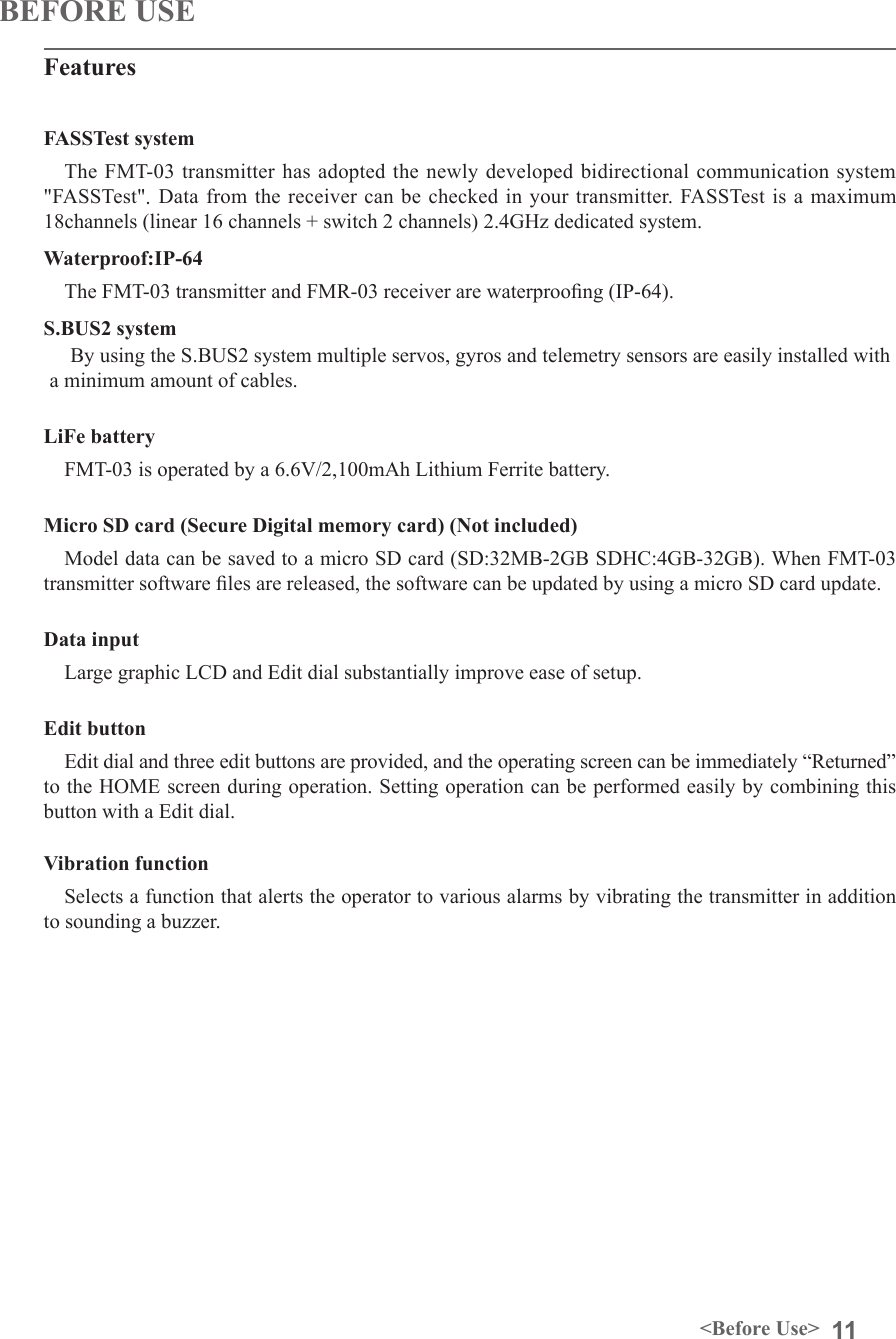
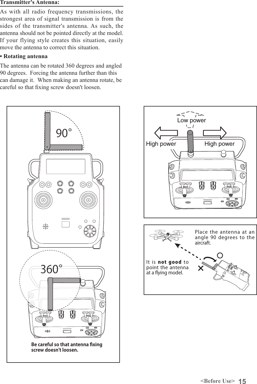
![13<Before Use>• FT2F2100BV2 transmitter battery pack - the (2,100mAh) transmitter LiFe battery pack may be easily exchanged with a fresh one to provide enough capacity for extended ying sessions.• Trainer cord - the optional training cord may be used to help a beginning pilot learn to fly easily by placing the instructor on a separate transmitter. Note: FMT-03 is connected by an exclusive trainer code by FMT-03 fellow. It isn't possible to connect with a transmitter of the different model.• Servos - FMR-03 can use only futaba S.BUS2 servos.• Telemetry sensor - please purchase an optional sensor, in order to utilize bidirectional communication system and to acquire the information from a model high up in the sky. [Temperature sensor : SBS-01T/TE] [Altitude sensor : SBS-01A] [RPM sensor magnet type : SBS-01RM][RPM sensor optical type : SBS-01RO] [RPM sensor brushless motor type : SBS-01RO] [GPS sensor : SBS-01G] [Voltage sensor : SBS-01V] [S.BUS servo sensor : SBS-01S] [Current sensor : SBS-01C]• Y-harnesses, servo extensions, hub,etc - Genuine Futaba extensions and Y-harnesses, including a heavy-duty version with heavier wire, are available to aid in your larger model and other installations.• Receivers - various models of Futaba receivers may be purchased for use in other models. (Receivers for FASSTest types are available.)The following additional accessories are available from your dealer. Refer to a Futaba catalog for more information:](https://usermanual.wiki/Futaba/FMT-03-24G.User-Manual-Part-I-Rev-01-170210/User-Guide-3285339-Page-13.png)
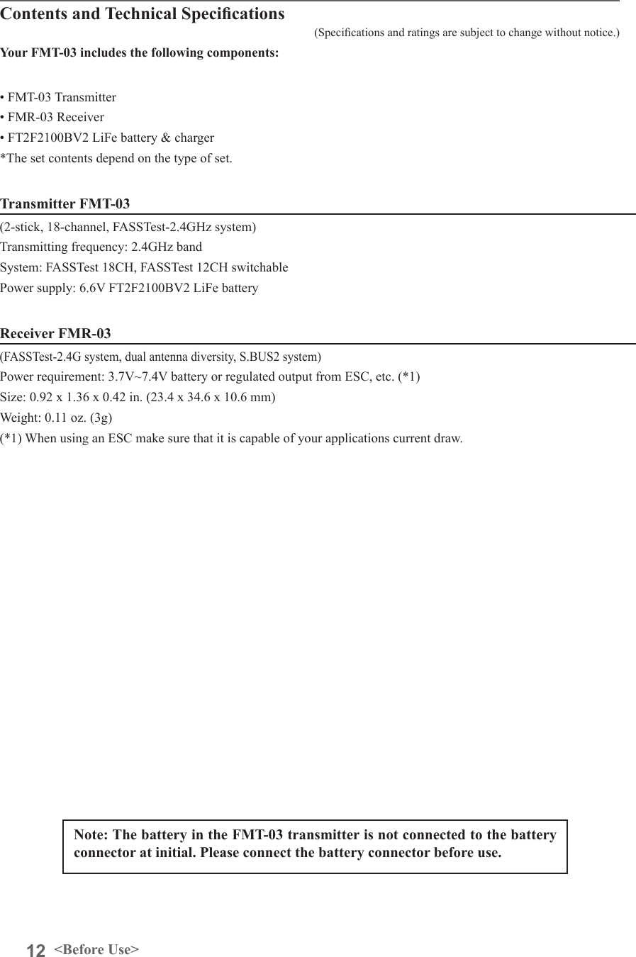
![28 <Basic Operation>BASIC OPERATIONHow to charge the LiFe battery FT2F2100BV2 for the transmitterDANGERThe LiFe battery FT2F2100BV2 is only for your FMT-03. Do not use this battery for other equipment.Be sure to use the attached special charger to charge the battery.[Method of charging battery]Battery ChargingBefore charging battery, read the "Cautions for handling battery and battery charger" in the section "Battery Safety and Handling Instructions".●Special charger●AC outletTo FMT-03 charge connectorTransmitter Batt.Charging displayRed solidChargingCharge completionGreen solidRed blinkor1.Plug the transmitter cord of the special charger into the charging connector in the transmitter. 2. Plug the charger into an AC outlet. 3. Check that the charging LED lights. When the battery will not be used for a long time, to prevent it from deteriorating we recommend that it be kept in about the half capacity state instead of fully charged. Also be careful that the battery does not en-ter the over-discharged state due to self-discharge. When the transmitter will not be used for a long time, you should always remove its battery. Periodically (about every 3 months) charge the battery.The charging time when charging the FT2F2100BV2 battery with the optional special charger is approxi-mately 3 hours. 4. Disconnect the charge plug.5. Disconnect the AC plug.](https://usermanual.wiki/Futaba/FMT-03-24G.User-Manual-Part-I-Rev-01-170210/User-Guide-3285339-Page-28.png)
![29<Basic Operation>How to turn transmitter power ON/OFF When turning on the power, the FMT-03 transmitter will begin emmiting RF automatically after it conrms the surrounding RF conditions. When turning on the power of the transmitter1. Turn on the power switch of the transmitter.How to stop the transmitter1. Turn off the power switch of the transmitter.*The transmitter shuts down at once.Low battery alarm When the battery voltage reaches 6.2V, an audible alarm will sound. Land your aircraft immediately. It can change from 6.0V to 7.6V by [SOUND] of [SYSTEM MENU]. It recommends using it with an initial value. Registration of the user's nameIf so desired, the FMT-03 transmitter can indicate the owner's name. User's name setup screen1. Turn on the power of the transmitter.2. Select [USER NAME] in the system menu and Push the RTN button.*The user name set up screen appears. Current user name Input BoxChanging the user name1. Change the user name as described below: [Moving cursor in input box] Select[←]or[→],andpushtheRTNbutton. [Deleting a character] When [DELETE] is selected and the RTN buttonispushed,thecharacterimmediatelyafter the cursor is deleted. [Adding a character] When a candidate character is selected from the character list and the RTN button ispushed,thatcharacterisaddedattheposition immediately after the cursor.*A name of up to 12 characters long can be entered as the user name. (A space is also counted as 1 character.)2.Attheendofinput,select[ENTER]andpushthe RTN button. (To terminate input and returntotheoriginalstate,select[CANCEL]and push the RTN button.)Push and holdON OFF](https://usermanual.wiki/Futaba/FMT-03-24G.User-Manual-Part-I-Rev-01-170210/User-Guide-3285339-Page-29.png)
![32 <Basic Operation>Key lockTo prevent the data from being changed by erroneous pushing of the edit dial during flight, a function which makes an edit dial impossible temporarily. How to lock1. The home screen is displayed.2. Push the S1 button for about 1 second. "LOCK" is displayed and the edit dial is disabled.How to unlock1. Push the S1 button for about 1 second in the edit dial locked state. The edit dial is enabled again.STARTUP LOCKAuto Lock functions automatically when the model changes or power is turned on.*To temporarily allow access to the FMT-03 programming push and hold the S1 bitton for one second. Please note, the Auto Lock function timer will resume immediately once again.*A PIN can also be set to protect the set data.AUTOMATIC LOCK Auto Lock functions automatically when there is no operation from the HOME screen display for a chosen number of seconds.*Two kinds of automatic locks can be chosen by [DISPLAY] of [SYSTEM MENU].](https://usermanual.wiki/Futaba/FMT-03-24G.User-Manual-Part-I-Rev-01-170210/User-Guide-3285339-Page-32.png)
![33<Basic Operation> Link procedure (FMT-03 ⇔FMR-03)Each transmitter has an individually assigned, unique ID code. In order to start operation, the receiver must be linked with the ID code of the transmitter with which it is being paired. Once the link is made, the ID code is stored in the receiver and no further linking is necessary unless the receiver is to be used with another transmitter. When you purchase additional FMR-03 receivers, this procedure is necessary; otherwise the receiver will not work. Link procedure1. Place the transmitter and the receiver close to each other within half (0.5m) meter. 2. Turn on the transmitter. 3. Select [SYSTEM TYPE] at the Linkage menu and access the setup screen shown below by pushing the RTN button.4.Whenyouusetworeceiversononemodel,you must change from [SINGLE] to [DUAL]. *Only two receivers can be used. In "DUAL",twosettingitemscomeout.Input,respectively.5. When changing battery fail-safe voltage fromtheinitialvalue3.8V,voltageischanged here. 6. [RECEIVER-ID] is chosen by scrolling and the RTN button is pushed. The transmitter will emit a chime as it starts the linking process.7.Whenthetransmitterstartstochime,poweron the receiver. The receiver should link to the transmitter within about 1 second. 8.Iflinkingfails,anerrormessageisdisplayed.Bring the transmitter closer to the receiver and repeat the procedure above from Step 2.9. ACT will be chosen if telemetry is used. ItisINHwhennotusingit. Less than 0.5 mIn "Link" ModeReceiver ON:You can do this through the LINKAGE Menu and scroll to System and push RTN.ID of a primary receiver displays.InDUAL,aprimaryreceiverislinkpreviously.Next,asecondary receiver is link.ID of a secondary receiver displays.](https://usermanual.wiki/Futaba/FMT-03-24G.User-Manual-Part-I-Rev-01-170210/User-Guide-3285339-Page-33.png)
![37<Functions of System Menu>SYSTEM MENUSystem Menu functions table[DISPLAY]: LCD contrast and back light adjustment.[SYSTEM TIMER]: Resets the accumulated timer for each model.[USER NAME]: User name registration.[SOUND]: Various volume control and low battery setting.[H/W SETTING]: H/W reverse, stick mode, stick calibration, and switch position.[INFORMATION]: Displays the program version, micro SD card information, and language selection.[RANGE CHECK]: A transmitting output is lowered and the check before a ight is carried out.[S.BUS SERVO]: S.BUS servo setting.The System Menu sets up functions of the transmitter: This does not set up any model data.● Select [SYSTEM] at the home screen and call the system menu shown below by pushing the RTN button.● Scrolling the edit dial to select the function you want to set and call the setup screen by pushing the RTN button.S1<Edit dial>● Select the function name and return to the System menu by pushing the RTN button or pushing the Home/Exit button.●Access setup screenScrolling● Moving cursor](https://usermanual.wiki/Futaba/FMT-03-24G.User-Manual-Part-I-Rev-01-170210/User-Guide-3285339-Page-37.png)
![38 <Functions of System Menu>S1<Edit dial>LCD contrast adjustment1. Scrolling the edit dial to select "LCD CONTRAST" and push the RTN button to switch to the data input mode and adjust the contrast by turning the edit dial to the left and right. Setting range: (Lighter) 0 to 30 (Darker) Initial value: 15 Push the RTN button to end adjustment and return to the cursor move mode.*Adjust to the contrast while watching the screen display.*When you want to reset the contrast to the initial state, select "LCD CONTRAST" and push the RTN button for 1 second.Backlight brightness adjustment1. Scrolling the edit dial to select "BACKLIGHT BRIGHTNESS" and push the RTN button to switch to the data input mode and adjust the contrast by turning the edit dial to the left and right. Setting range: (Darker) 0 to 30 (Lighter) Initial value: 10 Push the RTN button to end adjustment and return to the cursor move mode.*Adjust to the brightness while watching the screen display.*When you want to reset the contrast to the initial state, select "BACKLIGHT BRIGHTNESS" and push the RTN button for 1 second.Back-light off-timer1. Select "Back-light timer" and push the RTN button to switch to the data input mode and adjust the back-light off-timer by scrolling the edit dial. "OFF TIMER": Adjust the time when the back-light turns off after operating the edit dial. Setting range: 10 to 240 sec (each 10 sec), OFF (always on) Initial value: 10 sec*When you want to reset the value to the initial state, push the RTN button for one second.2. Push the RTN button to end adjustment and return to the cursor mode.*If the back light is on for a long time, consumption current will increase. DISPLAY LCD contrast adjustment and automatic key lockThe following LCD screen adjustments and auto power off setting are possible:● Backlighting brightness adjustment● Backlighting off timer adjustment● Key lock setupStart lockAuto Lock functions automatically when the model changes or power is turned on.*To temporarily allow access to the FMT-03 programming push and hold the S1 button for one second. Please note, the Auto Lock function timer will resume immediately once again.1. Select "STARTUP LOCK" and push the RTN button to switch to the data input mode and adjust the ON or OFF by scrolling the edit dial. Setting range: ON or OFF Initial value: OFFSet PIN IDA PIN can also be set to protect the set data.*Please do not forget the ID you set here. You have to input the ID in order to unlock the ID lock on the home screen. If you do not need the ID lock feature, please set the ID for "00000000".1. Select "ID" and push the RTN button to switch to the ID input screen.2. Scrolling the edit dial to select "00000000" and push the RTN button to switch to the data input mode and adjust the number by turning the edit dial to the left and right. Push the RTN button to end adjustment and return to the cursor move mode.3. UNLOCK: Push the S1 button for about 1 second in the edit dial locked state. And input the ID you have set. The edit dial is enabled again.Automatic lockAuto Lock functions automatically when there is no operation from the HOME screen display for a chosen number of seconds.1. Scrolling the edit dial to select "AUTOMATIC LOCK" and push the RTN button to switch to the data input mode and adjust the time by turning the edit dial to the left and right. Setting range: INH, 0 to 120 (s) Initial value: INH● Select [DISPLAY] at the system menu and call the setup screen shown below by pushing the RTN button.● Select the function name and return to the System menu by pushing the RTN button or pushing the Home/Exit button.Scrolling● Moving cursor● Selecting mode● Adjusting valueA PIN can also be set to protect the set data.](https://usermanual.wiki/Futaba/FMT-03-24G.User-Manual-Part-I-Rev-01-170210/User-Guide-3285339-Page-38.png)
![39<Functions of System Menu>S1<Edit dial>● Select the function name and return to the System menu by pushing the RTN button or pushing the Home/Exit button.Timer selection1. Move the cursor to the [MODE] item and push the RTN button to switch to the data input mode. Select the mode by scrolling the edit dial and push the RTN button. TOTAL: Displays the total timer on the home screen. MODEL timer: Displays the model timer on the home screen. SYSTEM TIMER Resets the accumulated timer.This function resets the system timer displayed on the home screen.● FMT-03 has two type system timers. TOTAL timer: Displays the total accumulated time on the transmitter from the last time the timer was reset. MODEL timer: Displays the total accumulated time on each model from the last time the timer was reset.● System timer displayed on the home screen can be selected.● Select [SYSTEM TIMER] at the system menu and call the setup screen shown below by pushing the RTN button.Timer reset1. Move the cursor to the [SYSTEM TIMER] item and reset the timer to "00:00:00" by pushing the RTN button for 1 second. After reset, the timer restarts from "00:00:00".Scrolling● Moving cursor● Selecting mode](https://usermanual.wiki/Futaba/FMT-03-24G.User-Manual-Part-I-Rev-01-170210/User-Guide-3285339-Page-39.png)
![40 <Functions of System Menu>S1<Edit dial>● Select the function name and return to the System menu by pushing the RTN button or pushing the Home/Exit button.USER NAME User name registrationThis function registers the FMT-03 user name.*A name of up to 12 characters can be entered as the user name. (Space is also counted as 1 character.)User name registration1. Change the user name as described below: [Moving cursor in input box] Select [←] or [→], and push the RTN button. [Deleting a character] When [DELETE] is selected and the RTN button is pushed, the character immediately after the cursor is deleted. [Adding a character] When a candidate character is selected from the character list and the RTN button is pushed, that character is added at the position immediately after the cursor.*A name of up to 12 characters long can be entered as the user name. (A space is also counted as 1 character.)2. At the end of input, select [ENTER] and push the RTN button. (To terminate input and return to the original state, select [CANCEL] and push the RTN button.)(Character list 1/3)(Character list 2/3)(Character list 3/3)● Select [USER NAME] at the system menu and call the setup screen shown below by pushing the RTN button.● Push the S1 button to call next page. Scrolling● Moving cursorCurrent user nameInput boxCursor (blink)](https://usermanual.wiki/Futaba/FMT-03-24G.User-Manual-Part-I-Rev-01-170210/User-Guide-3285339-Page-40.png)
![41<Functions of System Menu>S1<Edit dial>● Select the function name and return to the System menu by pushing the RTN button or pushing the Home/Exit button.3 independent sound volumes: "WARNING", "VOICE" and others, are available."LOW BATTERY" adjusts low battery alarm voltage to match a battery.● Select [SOUND] at the system menu and access the setup screen shown below by pushing the RTN button.Sound volume operation1. Move the cursor to the [WARNING][VOICE] or [OTHER SOUND] item and push the RTN button to switch to the data input mode.2. Select the volume by scrolling the edit dial. *The display blinks.3. Push the RTN button.Low battery voltage operation1. Move the cursor to the [LOW BATTERY] item and push the RTN button to voltage to the data input mode.2. Select the voltage by scrolling the edit dial. *The display blinks.3. Push the RTN button.SOUND Turns off the buzzer.Scrolling● Moving cursor● Adjusting value](https://usermanual.wiki/Futaba/FMT-03-24G.User-Manual-Part-I-Rev-01-170210/User-Guide-3285339-Page-41.png)
![42 <Functions of System Menu>S1● Select the function name and return to the System menu by pushing the RTN button or pushing the Home/Exit button.<Edit dial>Operation direction reversal method1. Select [H/W REVERSE] and call the setup screen shown below by pushing the RTN button.2. Use the edit dial to move the cursor to the "MODE" item corresponding to the H/W (hardware) you want to reverse and push the RTN button to switch to the data input mode.3. Change the mode by turning the edit dial to the left or right. The display blinks. When the RTN button is pushed, the operation direction is reversed. (To terminate mode change, turn the edit dial or push the S1 button.) "NORM": Normal operation direction "REV" : Operation direction is reversed.H/W SETTING Hardware reverse and stick mode, stick calibration, switch positionH/W reverseThis function reverses the operation signal of the sticks, switches, trimmer levers, and knobs.Note: This setting reverses the actual operation signal, but does not change the display of the indicators on the display. Use the Normal mode as long as there is no special reason to use the Reverse mode.Stick modeThis function changes the stick mode of transmitter.Note: This will not change the throttle ratchet, etc. Those are mechanical changes that must be done by a Futaba service center.Note: After changing the mode, it is applied when setting a new model. It is not applied to an existing model.Stick calibrationJ1-J4 stick correction can be performed.Note: It does not carry out, when there is no necessity.SwitchFor set the switch type and position amount when the stock conguration is changed.● Select [H/W SETTING] at the system menu and call the setup screen shown below by pushing the RTN button.Operation direction reversal method1. Select [STICK MODE] and call the setup screen shown below by pushing the RTN button.2. Use the edit dial to move the cursor to the "STICK MODE" item and push the RTN button to switch to the data input mode.3. Change the mode by turning the edit dial to the left or right. The display blinks. When the RTN button is pushed, the stick mode is changed. (To terminate mode change, turn the edit dial or push the S1 button.) (J1)(J2)(J4)(J3)Mode J1 J2 J3 J41Aileron Throttle Elevator Rudder2 Aileron Elevator Throttle Rudder3 Rudder Throttle Elevator Aileron4 Rudder Elevator Throttle Aileron●Access setup screenScrolling● Moving cursor](https://usermanual.wiki/Futaba/FMT-03-24G.User-Manual-Part-I-Rev-01-170210/User-Guide-3285339-Page-42.png)
![43<Functions of System Menu>Operation switch setting method1. Select [SWITCH] and call the setup screen shown below by pushing the RTN button.2. Use the edit dial to move the cursor to the "SA-SH" item corresponding to the switch you want to change and push the RTN button to switch to the data input mode.3. Change the "2Pos" or "3Pos" by turning the edit dial to the left or right. The display blinks. It will decide, if the RTN button is pushed. (To terminate mode change, turn the edit dial or push the S1 button.) "3Pos": 3 position switch "2Pos" : 2 position switchStick calibration method*J3-J4 correction is described below. J1-J2 corrections are performed using the same procedure. 1. Select [CALIBRATION] and access the setup screen shown below by pushing the RTN button.2. Move the cursor to the J3-J4 button and push the RTN button.3. Move the J3-J4 stick to the neutral position and push the RTN button for one second.4. Set the J3-J4 stick fully to the bottom- right and wait until the buzzer sounds.5. Set the J3-J4 stick fully to the top-left and wait until the buzzer sounds.6. The above completes the correction operation. Operate and check if stick correction was performed normally.](https://usermanual.wiki/Futaba/FMT-03-24G.User-Manual-Part-I-Rev-01-170210/User-Guide-3285339-Page-43.png)
![44 <Functions of System Menu>S1<Edit dial>● Select the function name and return to the System menu by pushing the RTN button or pushing the Home/Exit button.Displays the program version, Micro SD card information, and product ID.The FMT-03 system program version information, micro SD card information (maximum and vacant number of model data), and product ID are displayed on the Information screen.*When the micro SD card is not inserted, the micro SD card information is not displayed.The language displayed in home, menu, and setup screen is selectable.Also, the unit of a telemetry display can also be changed.● Select [INFORMATION] at the system menu and call the setup screen shown below by pushing the RTN button.Information "VERSION": FMT-03 system program version information "MEMORY CARD SIZE": Maximum number of model data (Micro SD card) "CARD FREE SIZE": Vacant number of model data (Micro SD card)Language selection1. Use the edit dial to move the cursor to the "LANGUAGE" item and push the RTN button to switch to the data input mode.2. Change the language by turning the edit dial to the left or right. The display blinks. When the RTN button is pushed, the language is changed. (To terminate mode change, turn the edit dial or push the S1 button.)Unit system selection1. Use the edit dial to move the cursor to the "UNIT SYSTEM" item and push the RTN button to switch to the data input mode.2. Change the unit by turning the edit dial to the left or right. The display blinks. When the RTN button is pushed, the unit is changed. (To terminate mode change, turn the edit dial or push the S1 button.)INFORMATIONScrolling● Moving cursor● Selecting mode](https://usermanual.wiki/Futaba/FMT-03-24G.User-Manual-Part-I-Rev-01-170210/User-Guide-3285339-Page-44.png)
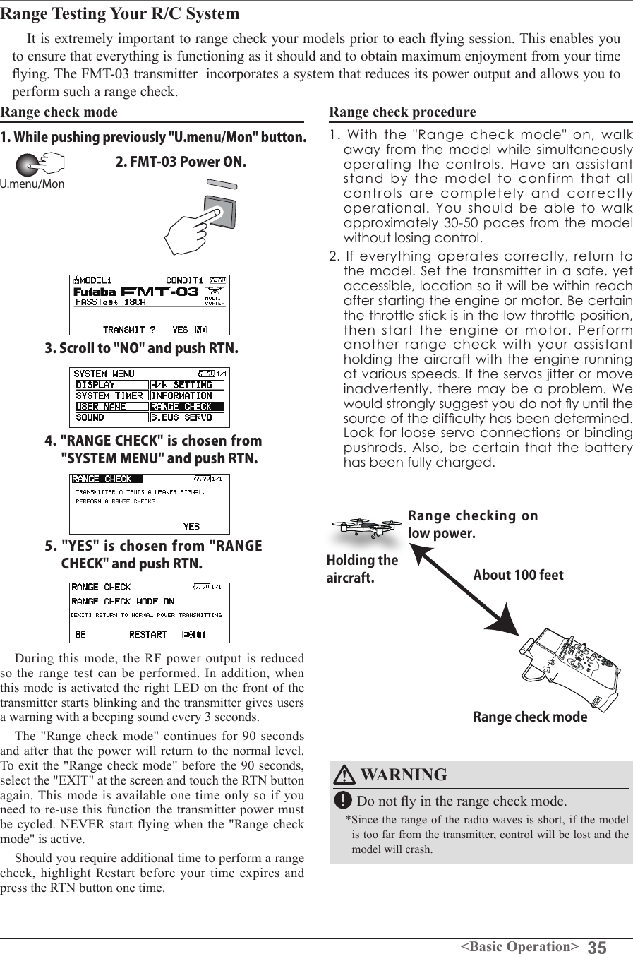
![45<Functions of System Menu>S1<Edit dial>● Select the function name and return to the System menu by pushing the RTN button or pushing the Home/Exit button.RANGE CHECK Before a ight ground range check.The 'range check mode' reduces the transmission range of the radio waves to allow for a ground range check.*The range check mode, when activated, will continue for 90 seconds unless the user exits this mode early. When the progress bar reaches 90 second mark, the RF transmission automatically returns to the normal operating power.● Pushing [U.menu/Mon] button is continued. →Turn ON the transmitter's power switch. (First, a throttle stick is made into a low position, and turns on a power supply.) It is displayed as "TRANSMIT?". "NO" is chosen and [RTN] is pushed.● [Yes] is chosen and [RTN] is pushed.● Remaining time of RANGE CHECK MODE.● Range Check mode is disabled. ● Range Check mode timer is returned to 90.Rotation Range Check method1. Pushing [U.menu/Mon] button is continued. →Turn ON the transmitter's power switch. (First, a throttle stick is made into a low position, and turns on a power supply.)It is displayed as "TRANSMIT?." "NO" is chosen and [RTN] is pushed. *For safety, the RANGE CHECK mode can not be selected while the RF transmission is active.2. In the system menu, choose the 'Range Check' selection from the menu options.3. The Range Check screen is displayed. To activate the Range Check mode push the [Yes] button. During the Range Check period, the RF power is reduced to allow the ground range tests to be performed.4. The Range Check function automatically exits after the 90 second time limit has expired. The count down time is displayed on the transmitter's screen. Should you complete the range check before the 90 seconds has pushed, push the [Exit] button.*When the [RESTART] button is pushed, the range check mode timer is returned to 90.*Please note, upon expiration of the 90 seconds, or when [Exit] is selected, the transmitter will automatically return to the normal RF operation as noted on the display. *Once the FMT-03 is transmitting at full power, it is not possible to enter the Range Check mode without first switching the transmitter Off and back On. This has been designed to prevent a modeler from inadvertently ying in the Range Check mode.5. When the [Exit] button is pushed, the Range Check mode is disabled and the FMT-03 will begin transmitting at full power.*After exiting the Range Check mode, the function cannot be selected again. To select the Range Check mode again you must cycle the transmitter power switch.● Select [RANGE CHECK] at the system menu and call the setup screen shown below by pushing the RTN button.WARNING Do not y in the range check mode.■Since the range of the radio waves is short, if the model is too far from the transmitter, control will be lost and the model will crash.Scrolling● Moving cursor](https://usermanual.wiki/Futaba/FMT-03-24G.User-Manual-Part-I-Rev-01-170210/User-Guide-3285339-Page-45.png)
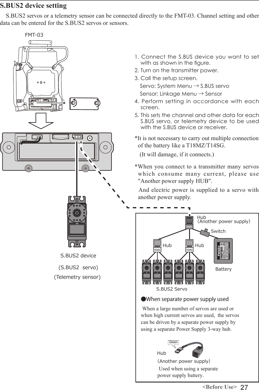
![46 <Functions of System Menu>S1● Select the function name and return to the System menu by pushing the RTN button or pushing the Home/Exit button.<Edit dial>Procedure for changing S.BUS/S.BUS2 servo setting1. Select [S.BUS Servo] of the System Menu.2. Wire the servo as shown in the gure above.3. Push [READ]. The ID and current setting of that servo are displayed.4. When multiple servos are connected change [INH] at the right side of the ID number on the screen to [ACT] and enter the ID of the servo you want to set.5. Set each item. (Please see the next page.) 6. Push [WRITE]. The settings are changed.S.BUS SERVOAn S.BUS/S.BUS2 servo can memorize the channel and various settings internally. Servo setting changes can be performed on the FMT-03 screen by wiring the servo as shown in the gure.● Call the following setting screen by pushing the [S.BUS Servo] button in the System Menu.●Servo ID numberIndividual ID numbers are memorized for your S.BUS servos in your FMT-03. When a servo is used (as shown at the right), the servo ID number is automatically read by the transmitter.If you use multiple S.BUS servos and do not want to change the settings on all that are mounted in a fuselage, only the desired servo in the group can be set by entering the ID of that specic servo.* With S.BUS/S.BUS2 servos of use, there are a function which can be used, and an impossible function and a display screen changes. (Only the function which can be used by a servo is displayed.)* After reading completion, with connection of the above gure, if a stick is moved, the test of operation of the servo can be operated and carried out.S.BUS/S.BUS2 servoFMT-03*It is not necessary to carry out multiple connection of the battery like a T18MZ/T14SG. (It will damage, if it connects.)Scrolling● Moving cursor● Push the S1 button to call next page. *When you connect to a transmitter with many servos which may consume extra current, please use "Another power supply HUB". And ensure power is supplied to extra servos with another power supply.](https://usermanual.wiki/Futaba/FMT-03-24G.User-Manual-Part-I-Rev-01-170210/User-Guide-3285339-Page-46.png)
![47<Functions of System Menu>S.BUS Servo Description of function of each parameter*There are some functions which can only be used with certain types of servos. • IDDisplays the ID of the servo whose parameters are to be read. It cannot be changed.• ChannelChannel of the S.BUS system is assigned to the servo. Always assign a channel before use.• ReverseThe direction in which the servo rotates can be changed.• Servo typeWhen “Retractable” is selected and the servo has been continuously stopped for 30 seconds, the dead band expands and unnecessary hold current due to external force is eliminated. When a new control signal enters, normal operation is resumed. When using the servo as a landing gear servo, select “Retractable”. Also adjust the servo travel to match the landing gear movement range.• Soft StartRestricts operation in the specified direction the instant the power is turned on. By using this setting, the first initial movement when the power is turned on slowly moves the servo to the specified position.• Stop Mode The state of the servo when the servo input signal is lost can be specified. The "Hold" mode setting holds the servo in its last commanded position even if using AM or FM system.• SmootherThis function changes smoothness of the servo operation relative to stick movement changes. Smooth setting is used for normal flight. Select the "OFF" mode when quick operation is necessary such as 3D.• Neutral OffsetThe neutral position can be changed. When the neutral offset is large value, the servo's range of travel is restricted on one side.• Speed ControlSpeeds can be matched by specifying the operating speed. The speed of multiple servos can be matched without being affected by motor fluctuations. This is effective for load torques below the maximum torque.However, note that the maximum speed will not be exceed what the servo is capable of even if the servos operating voltage is increased. • Dead bandThe dead band angle at stopping can be specified.[Relationship between dead band set value and servo operation]Small → Dead band angle is small and the servo is immediately operated by a small signal change.Large → Dead band angle is large and the servo does not operate at small signal changes.(Note) If the dead band angle is too small, the servo will operate continuously and the current consumption will increase and the life of the servo will be shortened.• Travel AdjustThe left and right travels centered about the neutral position can be set independently.• BoostThe minimum current applied to the internal motor when starting the servo can be set. Since a small travel does not start the motor, it essentially feels like the dead band was expanded. The motor can be immediately started by adjusting the minimum current which can start the motor.[Relationship between boost set value and servo operation]Small → Motor reacts less to a change and operation becomes smooth.Large → Initial response improves and output torque increases. However, if the torque is too large, operation will become rough.](https://usermanual.wiki/Futaba/FMT-03-24G.User-Manual-Part-I-Rev-01-170210/User-Guide-3285339-Page-47.png)
![48 <Functions of System Menu>• Boost ON/OFFOFF : The boost turns ON at the time of lower-demand operation. (In most cases)ON : The boost is always ON. (When quick operation is needed)• DamperThe characteristic when the servo is stopped can be set.When smaller than the standard value, the characteristic becomes an overshoot characteristic. If the value is larger than the standard value, the brake is applied before the stop position.Especially, when a large load is applied, overshoot, etc. are suppushed by inertia and hunting may occur, depending on the conditions. If hunting (phenomena which cause the servo to oscillate) occurs even though the Dead Band, Stretcher, Boost and other parameters are suitable, adjust this parameter to a value larger than the initial value.[Relationship between damper set value and servo operation]Small → When you want to overshoot. Set so that hunting does not occur.Large → When you want to operate so that braking is not applied. However, it will feel like the servo response has slowed down.(Note) If used in the hunting state, not only will the current consumption increase, but the life of the servo will also be shortened.• StretcherThe servo hold characteristic can be set. The torque which attempts to return the servo to the target position when the current servo position has deviated from the target position can be adjusted.This is used when stopping hunting, etc., but the holding characteristic changes as shown below.[Relationship between stretcher and servo operation]Small → Servo holding force becomes weaker.Large → Servo holding force becomes stronger.(Note) When this parameter is large, the current consumption increases.• BuzzerWhen the power supply of a servo is interrupted or a loss of signal from the transmitter, the buzzer sound of about 2.5Hz continues sounding from a servo. (Even when the signal output of a transmitter is lost, a buzzer becomes until the signal of a servo is outputted normally.) The transmitter has been turned OFF ahead of a servo power supply → The buzzer sound of about 1.25 Hz continues sounding to show that the servo power supply is still turned on.(Do not insert or remove the servo connector while the receiver power is ON. A buzzer may sound by incorrect recognition.) *Buzzer sound is generated by vibrating the motor of a servo. Since a lot of current is consumed and a servo generates heat during buzzer sounds, please do not operate the feature more than needed or do not continue sounding a buzzer for a long time.](https://usermanual.wiki/Futaba/FMT-03-24G.User-Manual-Part-I-Rev-01-170210/User-Guide-3285339-Page-48.png)
![49<Functions of Linkage Menu>FUNCTIONS OF LINKAGE MENUThe Linkage Menu is made up of functions which perform model addition, model type selection, frequency setting, end point setting, and other model basic settings.The functions which can be selected depend on the model type. A typical menu screen is shown below.Linkage Menu functions table[SERVO MONITOR]: Displays the servo test and operation position[MODEL SELECT]: Model addition, call, deletion, copy, model name setting[MODEL TYPE]: Model type, wing type, swash type, etc. selection[SYSTEM TYPE]: System mode selection, link of a transmitter and receiver, area mode selection[FUNCTION]: Channel assignment of each function can be changed[SUB-TRIM]: Adjusts the neutral position of each servo[SERVO-REVERSE]: Servo direction reversal[FAIL SAFE]: Fail safe function and battery fail safe function setting [END POINT]: Servo basic rudder adjustment and limit setting[THROTTLE CUT]: Stops the engine safely and easily (airplane and helicopter only)[IDLE DOWN]: Lowers the idle speed of the engine (airplane and helicopter only)[TIMER]: Timer setting[T1-T6 SETTING]: Control step amount and mode selection of the digital trim[MULTIPROP]: CH is extended by MPDX-1 of an option[FUNCTION NAME]: Function name can be changed[TELEMETRY]: Displays various data sent from the receiver[SENSOR]: Various telemetry sensors setting[TELE.SETTING]: Various telemetry sensors setting[WARNING]: Mixing warning normal reset [TRAINER]: Starts and sets the trainer system.[STICK ALARM]: Can be set so that an audible alarm sounds once when the throttle stick reaches the set position[DATA RESET]: Model memory set data reset (by item)● Select [LINKAGE] at the home screen and call the linkage menu shown below by pushing the RTN button.● Use the edit dial to select the function you want to set and call the setup screen by pushing the RTN button. S1● Select the function name and return to the Linkage menu by pushing the RTN button or pushing the Home/Exit button. ●Calling setup screenScrolling● Moving cursor● Push the S1 button to call next page.](https://usermanual.wiki/Futaba/FMT-03-24G.User-Manual-Part-I-Rev-01-170210/User-Guide-3285339-Page-49.png)
![50 <Functions of Linkage Menu>S1<Edit dial>● Select the function name and return to the Linkage menu by pushing the RTN button or pushing the Home/Exit button.WARNING Don't set a servo test mode when the drive motor is connected and the engine is powered or running.■Inadvertent rotation of the motor or acceleration of the engine is extremely dangerous.SERVO MONITOR Servo Test & Graph Display / Displays servo positions.This is used for testing servo movement. “Moving Test” (repetition mode) and “Neutral Test” (xed position mode) are available. The “Neutral Test” is good for finding the neutral position of a servo horn.In order to prevent any potential difficulties, the servo test function will be inoperable, or inaccessible, under certain conditions. Specically, the Servo Test function is not operational if the Throttle Cut is ON in either airplane or helicopter modes; or if the Throttle Hold is ON in Helicopter mode.● Select [SERVO MONITOR] at the linkage menu and call the setup screen shown below by pushing the RTN button.Servo test operation1. Use the edit dial to move the cursor to the [TEST] item and push the RTN button to switch to the data input mode. Select the test mode by turning the edit dial to the left or right and push the RTN button. [MOVING]: Mode which repeats operation of each servo [NEUTRAL]: Mode which locks each servo in the neutral position2. Use the edit dial to move the cursor to the [TEST] item and push the RTN button to switch to the data input mode. Select the [OFF] by turning the edit dial and push the RTN button. Testing is stopped.*The display screen is an example. The screen depends on the model type.Scrolling● Moving cursor● Selecting mode](https://usermanual.wiki/Futaba/FMT-03-24G.User-Manual-Part-I-Rev-01-170210/User-Guide-3285339-Page-50.png)
![51<Functions of Linkage Menu>S1<Edit dial>● Select the function name and return to the Linkage menu by pushing the RTN button or pushing the Home/Exit button.MODEL SELECT The Model Selection function performs model addition, call, deletion, copy, and model name setting. This function is used to load the settings of the desired model into the FMT-03’s memory.The settings may be selected from either the transmitter’s built-in memory or a micro SD card. Remember that up to 30 model memories are available in the transmitter.The name of the model stored in the transmitter and the micro SD card may be changed. This can be very useful to tell different models settings apart. Each model name can be as long as 15 characters, and the model name always appears in the display screen. The Copy function is used to copy one set of model data into a second memory within the transmitter and the micro SD card. It may be used for getting a head-start on setting up models with almost the same settings (only differences need to be modied, instead of entering the complete model from scratch). Also, this function may be used to make a backup copy of a model setup before any changes are made.Model call*Model data saved at models other than the model currently used or saved on a Micro SD card can be called.1. Use the edit dial to move to the save destination ("INTERNAL" or "MEM.CARD") and push the RTN button to switch to the data input mode. Select the location which is to save the desired model by turning the edit dial to the left or right. Push the RTN button. [INTERNAL]: Transmitter memory [MEM. CARD]: Micro SD card2. After using the edit dial to move the cursor to the desired model in the model list, push the RTN button.3. Use the edit dial to move to [SELECT].4. Push the RTN button. When a confirmation message is displayed and the RTN button is pushed again, calling is complete.*Transmission stops and a send with new model conrmation message ("TRANSMIT?") appears.5. To start transmission, use the edit dial to select [YES] and then push the RTN button. To not transmit, select [NO] and push the RTN button.Model addition*A new model can be added to the transmitter memory or Micro SD card. 1. Use the edit dial to move the cursor to the save destination ("INTERNAL" or "MEM. CARD) and push the RTN button to switch to the data input mode. Select the save destination by turning the edit dial to the left or right. Push the RTN button. [INTERNAL]: Transmitter memory [MEM. CARD]: Micro SD card2. Use the edit dial to move to [NEW].3. Push the RTN button. A conrmation message appears. Push the RTN button again.*The model type setup screen and frequency setup screen are automatically displayed. Conrm or change the model type and frequency.*A starting transmission with new model confirmation message ("TRANSMIT") appears.4. To start transmission, use the edit dial to select [YES] and then push the RTN button. To not transmit, select [NO] and push the RTN button.*The added model appears in the model list.● Select [MODEL SELECT] at the linkage menu and call the setup screen shown below by pushing the RTN button.*The display screen is an example. The screen depends on the model type.(Model list)●"Save to" [INTERNAL]: transmitter memory [MEM.CARD]: Micro SD cardScrolling● Moving cursor● Selecting mode](https://usermanual.wiki/Futaba/FMT-03-24G.User-Manual-Part-I-Rev-01-170210/User-Guide-3285339-Page-51.png)
![52 <Functions of Linkage Menu>Model deletion*The model stored in the transmitter memory or a Micro SD card can be deleted.*The current model can not be deleted.1. Use the edit dial to move the cursor to the save destination display ("INTERNAL" or "MEM. CARD") and push the RTN button to switch to the data input mode. Select the save destination by turning the edit dial to the left or right and push the RTN button. [INTERNAL]: Transmitter memory [MEM. CARD]: Micro SD card2. Use the edit dial to move the cursor to the model you want to delete in the model list and then push the RTN button.3. Move the cursor to [DELETE].4. Push the RTN button. When a confirmation message is displayed and the RTN button is pushed again, the model is deleted.Model name change*The current model's name can be changed.1.Use the edit dial to select the current model in the model list and then push the RTN button.2. Use the edit dial to move to [RENAME].3. Push the RTN button.*The model name setup screen is displayed.4. Change the model name as described below: [Moving cursor in input box] Select [←] or [→], and push the RTN button. [Deleting a character] When [DELETE] is selected and the RTN button is pushed, the character immediately after the cursor is deleted. [Adding a character] When a candidate character is selected from the character list and the RTN button is pushed, that character is added at the position immediately after the cursor.*A name of up to 8 characters long can be entered as the model name. (A space is also counted as 1 character.)5. At the end of input, select [ENTER] and push the RTN button. (To terminate input and return to the original state, select [CANCEL] and push the RTN button.)Model copy*A copy can be made of the current model.1.Use the edit dial to select the current model in the model list and then push the RTN button.2. Move to [COPY] with the edit dial.3. Push the RTN button.*The copy screen appears.4. Use the edit dial to move to the copy destination position at the bottom of the screen and push the RTN button to switch to the data input mode. Select the save destination by turning the edit dial and push the RTN button.5. Use the edit dial to move to [COPY].6. Push the RTN button. When a confirmation message is displayed and the RTN button is pushed again, the model data is copied.*FMT-03 accepts a Micro SD card formatted FAT le system, but it does not supports the long le name feature used in Windows or other modern operating systems. Thus FMT-03 can accept les whose name consists of only 8 characters or less. Furthermore, it supports only basic alphanumeric characters such as 'A" to 'Z", '0' to '9' and '_'.](https://usermanual.wiki/Futaba/FMT-03-24G.User-Manual-Part-I-Rev-01-170210/User-Guide-3285339-Page-52.png)
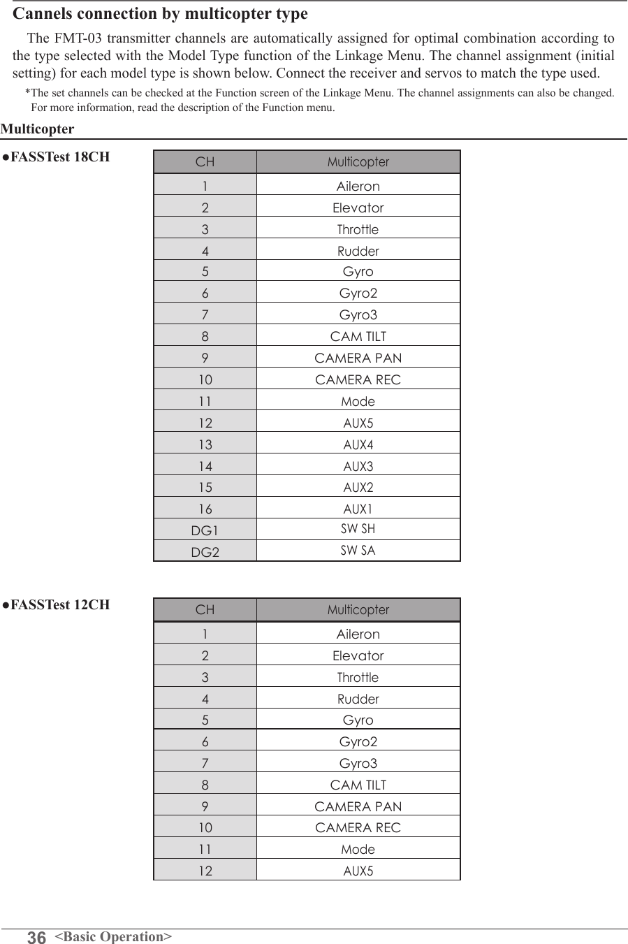
![53<Functions of Linkage Menu>S1● Select the function name and return to the Linkage menu by pushing the RTN button or pushing the Home/Exit button.<Edit dial>MODEL TYPE This function selects the model type from among multicopter, airplane, helicopter, and glider.(The display screen is an example. The screen depends on the model type.) Seven types of main wings and three types of tail wings are available for airplanes. Eight swash types are available for helicopters. Seven types of main wings and three types of tail wings are available for gliders. Functions and mixing functions necessary for each model type are set in advance at the factory.Note: The Model Type function automatically selects the appropriate output channels, control functions, and mixing functions for the chosen model type.When the Model Type Selection command is accessed, all of the data in the active memory is cleared (except the following swash type.) Be sure that you don’t mind losing this data, or back it up to another memory using the copying functions.When you change the helicopter swash type within the following each group, you can leave the setting data other than the SWASH function. In this case, confirmation screen appears. However, it is initialized when you change the swash type exceeding the group.Model type selection1. Use the edit dial to move the cursor to the item you want to change and then call the selection screen by pushing the RTN button. "TYPE": Model type "WING" (airplane/glider): Wing type "TAIL" (airplane/glider): Tail type "SWASH" (helicopter): Swash type2. Use the edit dial to move the cursor to the type you want to change and select the type by pushing the RTN button.*When the model type was changed, the wing type, tail type, or swash type selection screens sequentially appear according to the model. Finally, the blinking confirmation message "MODEL TYPE CONFIRMATION" appears.3. Push the RTN button to execute the change. (Operate the edit dial or S1 button to stop the change.)*The model types which are displayed (which can be selected) depend on the type of receiver used. See Servo Connection by Model Type.● Select [MODEL TYPE] at the linkage menu and call the setup screen shown below by pushing the RTN button.Swash type group A:H-1, H-2, H-3, HR3, HN3, and HE3Swash type group B:H-4, H-4X●Calling setup screenScrolling● Moving cursor● Selecting modeFMT-03 is equipped with a stick of multi-copter exclusive use. Therefore it's unsuitable for use of an airplane, a glider and a helicopter.](https://usermanual.wiki/Futaba/FMT-03-24G.User-Manual-Part-I-Rev-01-170210/User-Guide-3285339-Page-53.png)
![54 <Functions of Linkage Menu>S1<Edit dial>● Select the function name and return to the Linkage menu by pushing the RTN button or pushing the Home/Exit button.System Type selectionThe FMT-03 is for 2.4GHz only. The system can be changed from among 2 choices: FASSTest 18CH and FASSTest 12CH which can be chosen by FMR-03 set. *If you change the System Type, other model data is not reset.*After any change, remember to test the model and should fully check servo direction and a motion.*Analog servos cannot be used with the FMR-03 in the FASSTest 12CH mode.SYSTEM TYPE System mode setting, Receiver linkReceiver linkingThe receiver will only be controlled (without being affected by other transmitters) by the transmitter it is linked to. When using a receiver other than one purchased as a set, linking is necessary.Moreover, a re-link is required when a new model is added by model selection, and the time of system type change.Dual receiver function (only FASSTest 18CH mode)Dual receivers can be linked with the FMT-03. Two receivers are recognized individually by ID numbers. Two sets of receivers can be used as a set in the model. Separate fail-safe voltage can be set to each receiver.However, telemetry cannot be used for the 2nd receiver. Battery fail-safe voltage setup (only FASSTest mode)The voltage which battery fail-safe activates, can be set when you link. (3.5-8.4V) The receiver memorizes the setting as it was at link.Suggested setting voltages are as follows.• 4 cells NiCd or NiMH (Normal: 4.8v) = 3.8 v• 2 cells LiFe (Normal: 6.6 v) = 5.2 ~ 5.4 v• 2 cells LiPo (Normal: 7.4 v) = 6.6 ~ 6.8 vIt is a rough reference value.Since it changes with servos carried in the condition and the model of a battery, please set to your own model in a battery consumption current.● Select [SYSTEM] in the Linkage menu and access the setup screen shown below by pushing the RTN button.P.33Linking method Cases when linking is necessary:・When using a receiver other than the initial setting.・When the communication system was changed.(FASSTest 18CH ↔FASSTest 12CH etc. )・When a new model was created by model selection.Scrolling● Moving cursor● Selecting mode● Adjusting value](https://usermanual.wiki/Futaba/FMT-03-24G.User-Manual-Part-I-Rev-01-170210/User-Guide-3285339-Page-54.png)
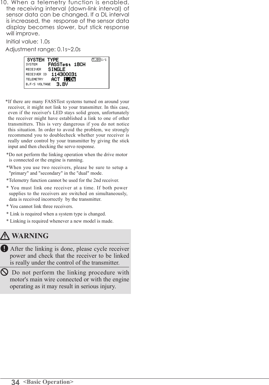
![55<Functions of Linkage Menu>Telemetry function (FASSTest 18CH mode only)To use the telemetry function, set “Telemetry” to “ACT”.DL Interval (FASSTest 18CH mode only)When a telemetry function is enabled, the receiving interval (down-link interval) of sensor data can be changed. If a DL interval is increased, the response of the sensor data display becomes slower, but stick response will improve. System Type selection procedure1. Move the cursor to the [FASSTest-18CH] item and push the RTN button to switch to the data input mode. 2. Select the system type by scrolling the edit dial. [FASSTest 18CH][FASSTest 12CH]*An example of selections for each system is on the following page.3. Push the RTN button to end adjustment and return to the cursor mode.Dual receiver function (only FASSTest 18CH mode) procedure1. Move the cursor to the [SINGLE] item and push the RTN button to switch to the data input mode. 2. Select the [SINGLE] or [DUAL] by scrolling the edit dial.3. Push the RTN button to end adjustment and return to the cursor mode.Telemetry ACT/INH procedure1. Move the cursor to the TELEMETRY [ACT] item and push the RTN button to switch to the data input mode. 2. Select the [ACT] or [INH] by scrolling the edit dial.3. Push the RTN button to end adjustment and return to the cursor mode.DL Interval set procedure1. Move the cursor to the TELEMETRY DL [1.0s] item and push the RTN button to switch to the data input mode. 2. Select the DL time by scrolling the edit dial. If a DL interval is increased, the response of the sensor data display becomes slower, but stick response will improve. Initial value: 1.0s Adjustment range : 0.1s~2.0s3. Push the RTN button to end adjustment and return to the cursor mode.In DUAL, a primary receiver is link previously. Next, a secondary receiver is link.ID of a Primary receiver displays.ID of a Secondary receiver displays.](https://usermanual.wiki/Futaba/FMT-03-24G.User-Manual-Part-I-Rev-01-170210/User-Guide-3285339-Page-55.png)
![56 <Functions of Linkage Menu>S1<Edit dial>● Select the function name and return to the Linkage menu by pushing the RTN button or pushing the Home/Exit button.FUNCTION Channel assignment of each function can be changed.Function change1. Use the edit dial to move the cursor to the "FUNCTION" item of the channel you want to change and push the RTN button.*The function selection screen is displayed.2. Use the edit dial to move the cursor to the function name you want to set and push the RTN button.*The function name blinks.3. Push the RTN button to execute the change. (When you want to cancel this operation, operate the edit dial or S1 button.)*Multiple channels can be assigned to one function.Operation control change1. Use the edit dial to move the cursor to the "CONTROL" item of the channel you want to change and push the RTN button.*The control selection screen is displayed.2. Use the edit dial to move the cursor to the control you want to change, and push the RTN button.*The same control can be assigned to multiple channels.*The setting can be changed for each condition. After the set mode is changed from group mode [G] to single mode [S] at the control selection screen, only that condition setting is changed by control change; setting of other conditions remains the same.(The display screen is an example. The screen depends on the model type.)● Select [FUNCTION] at the linkage menu and call the setup screen shown below by pushing the RTN button.● Trim operation mode"COMB": Combination mode"SEPAR": Separate modeWhen you select model and wing (swash) types, you will find that the optimized combinations of servo output channels and functions have been already preset. If you would like, you can freely change combinations of servo output channels, functions (aileron, elevator, etc), and control (sticks, switches, and trim levers). *You can also assign the same function to multiple servo output channels such as assigning elevator function to CH2 and CH3.Channel ReplacementWhen the channel is replaced in the function menu, replaced channel uses the setting data (End point, SUB-TRIM, REVERSE, F/S, and B-F/S, etc.).Servo Output ChannelsFor FASSTest 12CH mode, you can set 12 linear channels and two digital channels. For FASSTest 18CH mode, you can set 16 linear channels and two digital channels.*DG1/2 (digital channels) These channels can function as switched channels. You can freely change combinations between servo output channels and input controls (sticks, switches, and trim levers).Motor FunctionIf you have either a glider or airplane model type selected, and choose to activate the motor function, a reverse setting screen is displayed. *If "YES" is selected, the output is reversed. If "NO" is selected, the output is normal.Scrolling● Moving cursor● Selecting mode● Push the S1 button to call next page.](https://usermanual.wiki/Futaba/FMT-03-24G.User-Manual-Part-I-Rev-01-170210/User-Guide-3285339-Page-56.png)
![57<Functions of Linkage Menu>Trim setting Use the edit dial to move the cursor to the "TRIM" item of the channel you want to change and push the RTN button.*The trim setup screen is displayed. The following items can be set at the trim setup screen:*The setting can be changed for each condition. After the set mode is changed from group mode [G] to single mode [S] at the control selection screen, only that condition setting is changed by control change; setting of other conditions remains the same.Trim selection Use the edit dial to move the cursor to the trim, lever, etc. you want to set and push the RTN button.*The setting can be changed.Trim rate setting Use the edit dial to move the cursor to the [RATE] item and push the RTN button to switch to the data input mode. Set the trim rate by turning the edit dial. Initial value: +30% Adjustment range : 0~150%(When the RTN button is pushed for 1 second, the trim rate is reset to the initial value.) Push the RTN button to end adjustment and return to the cursor move mode.Trim mode selection Use the edit dial to move the cursor to the [TRIM MODE] item and select the trim mode by turning the edit dial. [NORM]: Normal mode. Normal trim (parallel shift trim) operation. [ATL]: ATL operation mode. Maximum change near center by operation normally used with throttle trim. Reverse is also possible. [NORM]/[REV] selection is possible at the "ATL REV" item. [CENTER]: Maximum change near center by center trim operation.WARNING As a safety precaution to prevent the motor from starting unexpectedly, please switch off the motor accordingly. We also suggest removing the propeller from the motor as an additional precaution.](https://usermanual.wiki/Futaba/FMT-03-24G.User-Manual-Part-I-Rev-01-170210/User-Guide-3285339-Page-57.png)
![58 <Functions of Linkage Menu>S1<Edit dial>● Select the function name and return to the Linkage menu by pushing the RTN button or pushing the Home/Exit button.SUB-TRIM Setting of neutral position of each servo.(The display screen is an example. The screen depends on the model type.)The Sub-Trim function is used to set the servo neutral position, and may be used to make fine adjustments to the control surface after linkages and pushrods are hooked up. When you begin to set up a model, be sure that the digital trims are set to their center position.Sub trim adjustment1. Use the edit dial to move the cursor to the channel you want to adjust and push the RTN button to switch to the data input mode.2. Adjust by turning the edit dial. Initial value: 0 Adjustment range: -240~+240 (steps)(When the RTN button is pushed for 1 second, sub trim is reset to the initial value.)*Before sub trim adjustment, adjustment of the linkage so that control surfaces need not use sub trim as much as possible is very important.3. Repeat this procedure for each channel.● Select [SUB-TRIM] at the linkage menu and call the setup screen shown below by pushing the RTN button.Scrolling● Moving cursor● Adjusting value● Push the S1 button to call next page.](https://usermanual.wiki/Futaba/FMT-03-24G.User-Manual-Part-I-Rev-01-170210/User-Guide-3285339-Page-58.png)
![59<Functions of Linkage Menu>S1● Select the function name and return to the Linkage menu by pushing the RTN button or pushing the Home/Exit button.<Edit dial>SERVO-REVERSE Use to reverse the throw direction.Servo Reverse changes the direction of an individual servo’s response to a control stick movement.For CCPM helicopters, be sure to read the section on Swash AFR before reversing any servos. With CCPM helicopters, always complete your servo reversing prior to any other programming. If you use pre-built Airplane/Sailplane functions Servo reversing procedure*After linkage of a new model is complete, check whether or not each servo is connected to the correct channel.*Next, determine whether you need to reverse any channels by moving each stick.1. Use the edit dial to move the cursor to the channel you want to reverse and push the RTN button to switch to the data input mode.2. Turn the edit dial and change the display to [REVERSE] (or [NORMAL]).*The display blinks.3. When the RTN button is pushed, servo operation is reversed. (Operate edit dial or S1 button to stop reversal.)*Repeat the operation above for each channel that must be reversed.that control multiple servos, it may be confusing to tell whether the servo needs to be reversed or a setting in the function needs to be reversed. See the instructions for each specialized function for further details. Always check servo direction prior to every ight as an additional precaution to conrm proper model memory, hook ups, and radio function.(The display screen is an example. The screen depends on the model type.)● Select [SERVO REVERSE] at the linkage menu and call the setup screen shown below by pushing the RTN button.Scrolling● Moving cursor● Selecting mode● Push the S1 button to call next page.](https://usermanual.wiki/Futaba/FMT-03-24G.User-Manual-Part-I-Rev-01-170210/User-Guide-3285339-Page-59.png)
![60 <Functions of Linkage Menu>S1<Edit dial>● Select the function name and return to the Linkage menu by pushing the RTN button or pushing the Home/Exit button.(The display screen is an example. The screen depends on the model type.)● Select [FAIL SAFE] at the linkage menu and call the setup screen shown below by pushing the RTN button.FAIL SAFE Sets the servos operating position when transmitter signals can no longer be received or when the receiver battery voltage drops.The Failsafe function may be used to set up positions that the servos move to in the case of radio interference.You may set either of two positions for each channel: Hold, where the servo maintains its last commanded position, or Failsafe, where each servo moves to a predetermined position. You may choose either mode for each channel. The FMT-03 system also provides you with an advanced battery monitoring function that warns you when the receiver battery has only a little power remaining. In this case, each servo is moved to the dened failsafe position. The battery failsafe may be released by operating a predened control on the transmitter, do not continue to fly, land as soon as possible. Remember, if the predefined control suddenly moves to a position you did not command, land at once and check your receiver Fail safe setting procedure1. Move the cursor to the "F/S" item of the channel you want to set and push the RTN button to switch to the data input mode.2. Select the F/S mode by scrolling the edit dial. A conrmation message appears. *The display blinks.3. Push the RTN button. (Push the S1 button to stop setting.)*The channel switches to the F/S mode.4. Move the cursor to the "POS" item. Hold the corresponding stick, knob, slider, etc. in the position you want the servo to move to when the fail safe function is activated and push the RTN button for one second.*The set position is displayed in percentage.*If you want to return that channel to the hold mode, move the cursor to the "F/S" item and push the RTN button to switch to the data input mode. Select the F/S mode by scrolling the edit dial. A conrmation message appears and then change the mode by pushing the RTN button.battery.Denes servo position when signals are lost and when receiver battery voltage becomes low.WARNING For safety, always set the fail safe functions.●Remember to set the throttle channel fail safe function so that the servo moves to the maximum slow side for airplanes and to the slow side from the hovering position for helicopters. Crashing of the model at full high when normal radio waves cannot be received due to interference, etc., is very dangerous.●If the battery fail safe is reset by the throttle stick, it may be mistaken for an engine malfunction and will be reset at throttle slow and the model will continue to y. If you have any doubts, immediately land.Battery fail safe setting procedure Battery fail safe can be set for each channel by the same method as the fail safe setting procedure. Select and set the "B.F/S" item. [ON]: Battery fail safe function ON [OFF]: Battery fail safe function OFFBattery fail safe release switch setting This function temporarily releases the battery fail safe function, so the model can recover after the battery fail safe function was activated by a drop in the receiver battery voltage. This setting selects the switch which releases the battery fail safe function.1. Move the cursor to the [RELEASE B.F/S] item in the setup screen (last page).2. Push the RTN button.*The switch selection screen is called.*For a detailed description of the switch selection and ON/OFF direction setting method, see [Switch Setting Method] at the back of this manual.Scrolling● Moving cursor● Selecting mode● Push the S1 button to call next page.](https://usermanual.wiki/Futaba/FMT-03-24G.User-Manual-Part-I-Rev-01-170210/User-Guide-3285339-Page-60.png)
![61<Functions of Linkage Menu>S1<Edit dial>● Select the function name and return to the Linkage menu by pushing the RTN button or pushing the Home/Exit button.END POINT Sets the travel, limit point, and speed of each servo.The End Point function adjusts the left and right servo throws, generates differential throws, and will correct improper linkage settings. The travel rate can be varied from 30% to 140% in each direction on channels 1 to 12. Also, the limit point where servo throw stops may be varied from 0% to 155%.Servo travel adjustment1. Use the edit dial to move the cursor to the "TRAV." item of the channel you want to adjust and push the RTN button to switch to the data input mode.2. Turn the edit dial to adjust the rate. Initial value: 100% Adjustment range: 30%~140%(When the RTN button is pushed for 1 second, the rate is reset to the initial value.) Push the RTN button to end adjustment and return to the cursor move mode.3. Repeat this procedure for each rate.Limit point adjustment1. Use the edit dial to move the cursor to the "LIMIT" item of the channel you want to adjust and push the RTN button to switch to the data input mode.2. Turn the edit dial to adjust the limit point. Initial value: 135% Adjustment range: 0%~155%(When the RTN button is pushed for 1 second, the limit point is reset to the initial value.) Push the RTN button to end adjustment and return to the cursor move mode.3. Repeat this procedure for each limit point.NOTE: The servo speed setting is used to set the servo delay for each channel, from channel l to channel 12. The system uses the programmed speed (delay) to slow down servo position changes. The servo speed setting can be varied from 0 to 27 in each channel.Servo speed setting1. Use the edit dial to move the cursor to the "SPEED" item of the channel you want to adjust and push the RTN button to switch to the data input mode.2. Turn the edit dial to adjust the servo speed. Initial value: 0 Adjustment range: 0~27 (steps)(When the RTN button is pushed for 1 second, the servo speed is reset to the initial value.) Push the RTN button to end adjustment and return to the cursor move mode.3. Repeat this procedure for each channel.● Select [END POINT] at the linkage menu and call the setup screen shown below by pushing the RTN button.(The display screen is an example. The screen depends on the model type.)Scrolling● Moving cursor● Adjusting value● Push the S1 button to call next page.](https://usermanual.wiki/Futaba/FMT-03-24G.User-Manual-Part-I-Rev-01-170210/User-Guide-3285339-Page-61.png)
![62 <Functions of Linkage Menu>S1<Edit dial>● Select the function name and return to the Linkage menu by pushing the RTN button or pushing the Home/Exit button.THROTTLE CUT Stops the engine safely and easily. (Airplane and helicopter only)Throttle cut provides an easy way to stop the engine, by ipping a switch with the throttle stick at idle. The action is not functional at high throttle to avoid accidental dead sticks. The switch’s location and direction must be chosen, as it defaults to NULL.Throttle cut setting procedure*Perform the following settings before using the edit dial to move the cursor to the item to be set.1. Activate the function: Move the cursor to the [ACT/INH] item and push the RTN button to switch to the data input mode. Turn the edit dial to the left until the blinking changes from "INH" to "ACT" and then push the RTN button.2. Switch setting: Move the cursor to the [SWITCH] item and call the switch setup screen by Pushing the RTN button and select the switch and ON direction.(For a detailed description of the setting method, see [Switch Setting Method] at the back of this manual.)3. Throttle cut position setting: Move the cursor to the [CUT POSITION] item and push the RTN button to switch to the data input mode. Adjust the servo operation position at throttle cut operation by turning the edit dial to the left or right. Initial value: 17% Adjustment range: 0%~50%(When the RTN button is Pushed for 1 second, the servo operation position is reset to the initial value.) Push the RTN button to end adjustment and return to the cursor move mode.*With the selected cut switch ON and the throttle stick at idle; adjust the rate until the engine consistently cuts off. However, be sure that the throttle linkage is not pulled too tight and unreasonable force is not applied to the servo.● Select [THROTTLE CUT] at the linkage menu and call the setup screen shown below by pushing the RTN button.● Current throttle position ● Cut positionScrolling● Moving cursor● Selecting mode● Adjusting value](https://usermanual.wiki/Futaba/FMT-03-24G.User-Manual-Part-I-Rev-01-170210/User-Guide-3285339-Page-62.png)
![63<Functions of Linkage Menu>S1<Edit dial>● Select the function name and return to the Linkage menu by pushing the RTN button or pushing the Home/Exit button.IDLE DOWN Lowers the engine idling speed. (Airplane and helicopter only)The Idle Down function lowers the engines idle by ipping a switch with the throttle stick at idle. The action is not functional at high throttle to avoid accidental dead sticks. The switch’s location and direction must be chosen, as it defaults to NULL.Idle down setting procedure*Perform the following settings after using the edit dial to move the cursor to the item you want to set.1. Activate the function: Move the cursor to the [ACT/INH] item and push the RTN button to switch to the data input mode. Switch the blinking from "INH" to "ACT" by turning the edit dial to the left and then push the RTN button.2. Switch setting: Move the cursor to the [SWITCH] item, call the switch setup screen by pushing the RTN button, and select the switch and ON direction.(For a detailed description of the setting method, see [Switch Setting Method] at the back of this manual.)3. Offset rate setting: Move the cursor to the [OFFSET] item and push the RTN button to switch to the data input mode. Adjust the servo offset rate at idle down operation by turning the edit dial to the left or right. Initial value: 0% Adjustment range: -100%~100%(When the RTN button is pushed for 1 second, the offset rate is reset to the initial value.)*Maximum offset amount is near maximum slow.*When a minus rate is input, offset is applied to the high side. Push the RTN button to end adjustment and return to the cursor move mode.● Select [IDLE DOWN] at the linkage menu and call the setup screen shown below by pushing the RTN button.● Current throttle positionScrolling● Moving cursor● Selecting mode● Adjusting value](https://usermanual.wiki/Futaba/FMT-03-24G.User-Manual-Part-I-Rev-01-170210/User-Guide-3285339-Page-63.png)
![64 <Functions of Linkage Menu>S1<Edit dial>● Select the function name and return to the Linkage menu by pushing the RTN button or pushing the Home/Exit button.TIMER Timer settingThe Timer function may be set for any desired time, i.e. engine run time, specified times for competitions, etc. Two independent timers are provided for your use. The timers are stored independently with each model, meaning that when you switch between model setups, the timer associated with the new model is brought up automatically.The timers may be set to start and stop from the motion of any switch or stick. You may set the ON and OFF directions freely. Each timer has a capacity of up to 59 minutes 59 seconds.Timer setting*Perform the following settings after using the edit dial to move the cursor to the item you want to set.1. Up timer/down timer setting Move the cursor to the [MODE] item and push the RTN button to switch to the data input mode. Select the mode by moving the edit dial to the left or right and push the RTN button. [UP]: Up timer [DOWN]: Down timer2. Timer time setting Move the cursor to the [10]:[100] item and push the RTN button to switch to the data input mode. Set the time by turning the edit dial to the left or right. [00]:[00]:[min]:[sec] Push the RTN button to end adjustment and Each timer may be set for count-down or count up operation with a target time. If a target time is set and the timer reaches the set time, a buzzer sound for each count is generated.Countdown timers sound one short beep during the last twenty seconds and two short beeps during the last ten seconds before reaching the target, then a long tone at the target time, and continue counting with displaying a minus (-) sign. Count-up timers also beep the last twenty and ten seconds, beep the target time, and keep counting upwards until shut down.return to the cursor move mode.3. Switch setting Move the cursor to the item of the switch you want to set, call the switch setup screen by pushing the RTN button, and select the switch and ON direction.[For a detailed description of the setting method, see [Switch Setting Method] at the back of this manual.] [RESET SW]: Reset switch [START SW]: Start switch [STOP SW]: Stop switchTimer operation● Timer 1 and Timer 2 are started/stopped by pre-selected start/stop switch.● To reset a timer, operate the pre-selected reset switch, or move the cursor to the [RESET] display on the timer screen and push the RTN button.● Select [TIMER] at the linkage menu and call the setup screen shown below by pushing the RTN button.● The timer value is held even if the power is turned off or the model is switched.Memory →ON●Calling setup screenScrolling● Moving cursor● Selecting mode](https://usermanual.wiki/Futaba/FMT-03-24G.User-Manual-Part-I-Rev-01-170210/User-Guide-3285339-Page-64.png)
![65<Functions of Linkage Menu>Alarm mode*A mode which sounds an alarm every minute during the remaining time up to the timer alarm time.1. Change the setting by Pushing ↑or ↓button. [↑]: An alarm sounds every minute of the elapsed time from timer start. (Conventional mode) [↓]: An alarm sounds every minute of the remaining time up to the alarm time.HOUR mode*An HOUR mode counts up to 99 hours 50 minutes to the timer modes.● This mode is convenient when used at engine maintenance period and other long term measurements.● When the HORU mode is set, "xx(hour) : xx(minute)" is displayed on the count time display. Seconds are not displayed.● When the HORU mode is set, " : " blinks each second during timer operation.● When the HORU mode is set, the alarm function/lap time measurement function are inhibited.](https://usermanual.wiki/Futaba/FMT-03-24G.User-Manual-Part-I-Rev-01-170210/User-Guide-3285339-Page-65.png)
![66 <Functions of Linkage Menu>S1<Edit dial>● Select the function name and return to the Linkage menu by pushing the RTN button or pushing the Home/Exit button.T1-T6 SETTING Digital trim settingsThis function adjusts the digital trim's control step amount and operation mode (T1-T6).When the flight conditions are set, the trim operation can be coupled with among all the conditions which combination mode is selected.Trim position setting (neutral offset)1. Use the edit dial to move the cursor to the [POS] item and push the RTN button to switch to the data input mode. Set the trim position by turning the edit dial. Initial value: +0 (neutral position)(When the RTN button is pushed for 1 second, the control step amount is reset to the initial value.)2. Push the RTN button to end adjustment and return to the cursor move mode.Control step amount setting1. Use the edit dial to move the cursor to the [STEP] item and push the RTN button to switch to the data input mode. Set the control step amount by turning the edit dial. Initial value: 4 Adjustment range: 0(trim off)-200(When the RTN button is pushed for 1 second, the control step amount is reset to the initial value.)*When the value is made large, the change per step becomes larger.2. Push the RTN button to end adjustment and return to the cursor move mode.C; combination / S; separate mode selection1. Use the edit dial to move the cursor to the [C;COMB./S;SEPA.] item and change to blinking by turning the edit dial and select the mode by pushing the RTN button. [C;COMB]: Combination mode. The trim data are reected at all the ight conditions. [S;SEPA]: Separate mode. Trim adjustment for each ight condition.Trim display units● Percentage(%) display can be selected at trim.1. Select "TRIM UNIT" and turn the dial and switch the display to [%] or [--].*The display blinks. [%]: Trim is displayed in % units. [--]: Trim is displayed numerically as in the past.2. When the RTN button pushed, the setting is changed.● Select [T1-T6 SETTING] at the linkage menu and call the setup screen shown below by pushing the RTN button.Scrolling● Moving cursor● Selecting modeTrim lever T1-T6 isn't equipped in FMT-03.](https://usermanual.wiki/Futaba/FMT-03-24G.User-Manual-Part-I-Rev-01-170210/User-Guide-3285339-Page-66.png)
![67<Functions of Linkage Menu>S1<Edit dial>● Select the function name and return to the Linkage menu by pushing the RTN button or pushing the Home/Exit button.MULTIPROP CH is extended by MPDX-1 of an optionThe system has compatible with the Futaba MPDX-1 multiprop decoder. One channel can be expanded to 8 channels by using the MPDX-1 multiprop decoder. Up to two MPDX-1 can be used.*The trim step amount and trim rate are not reset.Multiprop selection1. Select the Linkage Menu multiprop setting [MULTIPROP] and push the RTN button.2. The MULTIPROP setup screen is displayed.3. Select [MP1] and push the RTN button.4. Scrolling the edit dial and switch the display to [MP1] or [MP2].*The display blinks. [MP1]: Multiprop 1 [MP2]: Multiprop 25. Push the RTN button.Channel setting1. Select [CH] and push the RTN button. Scrolling the edit dial and display the channel to which the MPDX-1 is connected.*To turn off the multiprop function, set [--] at CH.2. When the activated channel is selected and push the RTN button, the multiprop setting contents are displayed.Control setting1. Select the "CONTROL" row of the multiprop channel whose control you want to set and push the RTN button.2. A hardware selection screen is displayed. Select the hardware which is to set control and push the RTN button.Servo reverse setting1. Select the "REVERSE" row of the multiprop channel which is to be reversed and push the RTN button.2. Scrolling the edit dial and switch the display to [NORM] or [REV].*The display blinks. [NORM]: Normal mode [REV]: Reverse mode3. Push the RTN button.End Point Setting1. Select the " ←↑" row or " ↓→" row of the multiprop channel whose end point is to be set and switch to the data input mode by push the RTN button.2. Adjust the end point by scrolling the edit dial. Initial value : 100% Adjustment range : 30-100%3. After adjustment, push the RTN button.● Select [MULTPROP] at the linkage menu and call the setup screen shown below by pushing the RTN button.Scrolling● Moving cursor● Selecting mode](https://usermanual.wiki/Futaba/FMT-03-24G.User-Manual-Part-I-Rev-01-170210/User-Guide-3285339-Page-67.png)
![68 <Functions of Linkage Menu>S1<Edit dial>● Select the function name and return to the Linkage menu by pushing the RTN button or pushing the Home/Exit button.FUNCTION NAME Function name can be changedThe name of the spare functions (AUXILIARY1-8) can be changed for the full name (10 characters) or for the abbreviated name (4 characters).Function name change method1. Select [FUNCTION NAME] of the Linkage Menu and push the RTN button.2. The FUNCTION NAME setup screen is displayed.3. When the function whose name is be change is selected and the RTN button is pushed, a modication screen is displayed.4. Select the function to be renamed and select [RENAME] and push the RTN button. A character input screen is displayed. Input the function name.5. When [RESET] is selected and the RTN button is held down, the function name is set to the initial state function name.6. The function name may be displayed in 10 characters or 4 characters, depending on the setup screen. For 4 characters, display, input the function name as required.● Select [FUNCTION NAME] at the linkage menu and call the setup screen shown below by pushing the RTN button.Scrolling● Moving cursor● Push the S1 button to call next page.](https://usermanual.wiki/Futaba/FMT-03-24G.User-Manual-Part-I-Rev-01-170210/User-Guide-3285339-Page-68.png)
![69<Functions of Linkage Menu>S1<Edit dial>● Select the function name and return to the Linkage menu by pushing the RTN button or pushing the Home/Exit button.TELEMETRY Displaying data from the receiver This screen displays your choice of data from the receiver.Also warnings can be activated regarding other data from your aircraft. For example, if the receiver voltage drops, the user can be warned by an alarm (and vibration).*Only receiver voltage can be used in FASSTest 12CH mode.*The FASSTest 18CH mode can use all the telemetry functions. ● Select [TELEMETRY] in the Linkage menu and access the setup screen shown below by pushing the RTN button.● Push S1 button to advance to next page.How to see telemetry data1. Telemetry screen can be called select [TELEMETRY] in the Linkage menu and access the setup screen by pushing the RTN button. 2. If each item is chosen and the RTN button is pushed, an alarm setup can be performed with the minimum/maximum after a transmitter is turned on. *Receiver voltage can be checked immediately. An optional sensor will need to be attached to S.BUS2 of a receiver if you would like to see other information. *No special setup is necessary if each sensor displayed is left as in the default setup. Separate sensor ID is also unnecessary. However, if two or more of one kind of sensor is used, setup is required in the "SENSOR" menu.WARNING Do not watch the transmitter screen during ight.*You may loose sight of the aircraft during ight and this is extremely dangerous. Have an assistant on hand to check the screen for you. A pilot should NEVER take his eyes off his aircraft.Scrolling● Moving cursor● Receiver → Transmitter. The reception strength is shown.● Push the S1 button to call next page.](https://usermanual.wiki/Futaba/FMT-03-24G.User-Manual-Part-I-Rev-01-170210/User-Guide-3285339-Page-69.png)
![70 <Functions of Linkage Menu>S1<Edit dial>● Select the function name and return to the Linkage menu by pushing the RTN button or pushing the Home/Exit button.TELEMETRY : RECEIVER [BATTERY] Displaying data from the receiver battery voltageIn this screen, the battery voltage of a receiver is displayed.If it becomes higher or lower than the setting an alarm and/or vibration will alert you.*Only receiver voltage can be used in FASSTest 12CH mode.*The FASSTest 18CH mode can use all the telemetry functions.● Select [Rx-BATT.] in the TELEMETRY screen and access the setup screen shown below by pushing the RTN button.● Select [BATTERY] in the RECEIVER screen and access the setup screen shown below by pushing the RTN button.●A setup of the voltage on which the alarm operates.Scrolling● Moving cursor● Receiver battery voltage ● The maximum and the minimum when powering ON are shown. It will be preset, if a cursor is moved to this place and the RTN button is pushed for 1 second.● ↓The "down" arrow will indicate that an alarm will sound when the voltage drops to below the setting.● ALARM is chosen from BUZZER, VOICE, and INHIBIT. ● The ON/OFF switch of SPEECH is chosen.Alarm set 1. Move the cursor to the ↓ALARM item, and it chooses from BUZZER, VOICE, INHIBIT, and pushes RTN.2. When not operating vibrator, it is "VIBRATOR" to INHIBIT. TYPE1-3 will be chosen if it is made to operate.3. Move the cursor to the LIMIT [4.0V] item and push the RTN button to switch to the data input mode. 4. Ajust the rate by scrolling the edit dial. Initial value: 4.0V Adjustment range: 0.0V~100.0V*When the RTN button is pushed for one second, the rate is reset to the initial value.5. Push the RTN button. (To terminate the input and return to the original state, push the Home/Exit button.)TYPE 1TYPE 2TYPE 3"VIBRATOR" typeIf the following types are selected, the transmitter will vibrate during the warning.](https://usermanual.wiki/Futaba/FMT-03-24G.User-Manual-Part-I-Rev-01-170210/User-Guide-3285339-Page-70.png)
![71<Functions of Linkage Menu>S1<Edit dial>● Select the function name and return to the Linkage menu by pushing the RTN button or pushing the Home/Exit button.● Select [Rx-BATT.] in the TELEMETRY screen and access the setup screen shown below by pushing the RTN button.Alarm set 1. Move the cursor to the ↓ALARM item, and it chooses from BUZZER, VOICE, and INHIBIT, and pushes RTN.2. When not operating vibrator, it is "VIBRATOR" to INHIBIT. TYPE1-3 will be chosen if it is made to operate.3. Move the cursor to the LIMIT [4.0V] item and push the RTN button to switch to the data input mode. 4. Ajust the rate by scrolling the edit dial. Initial value: 4.0V Adjustment range: 0.0V~100.0V*When the RTN button is pushed for one second, the rate is reset to the initial value.5. Push the RTN button. (To terminate the input and return to the original state, push the Home/Exit button.)TYPE 1TYPE 2TYPE 3"VIBRATOR" typeIf the following types are selected, the transmitter will vibrate during the warning.TELEMETRY : RECEIVER [EXT BATT.] Displaying data from the EXT battery voltage portThe EXT-VOLT screen will display the data from the EXT-battery output from the R7008SB receiver. In order to use this function, it is necessary to connect external voltage connector of the R7008SB receiver to a CA-RVIN-700 or SBS-01V to the battery you desire to measure the voltage of the EXT-battery.You will be alerted by an alarm or vibration if the voltage set by you is exceeded.*FMR-03 isn't equipped with EXT-battery port.*Only receiver voltage will be received in the FASSTest 12CH mode.*The FASSTest 18CH mode will display all telemetry data.*CA-RVIN-700 must be installed in the aircraft.● Select [EXT BATT.] in the RECEIVER screen and access the setup screen shown below by pushing the RTN button.●A setup of the voltage on which the alarm operates.Scrolling● Moving cursor● EXT battery voltage ● The maximum and the minimum when powering ON are shown. It will be preset, if a cursor is moved to this place and the RTN button is pushed for 1 second.● ↓The "down" arrow will indicate that an alarm will sound when the voltage drops to below the setting.● ALARM is chosen from BUZZER, VOICE, and INHIBIT. ● The ON/OFF switch of SPEECH is chosen.](https://usermanual.wiki/Futaba/FMT-03-24G.User-Manual-Part-I-Rev-01-170210/User-Guide-3285339-Page-71.png)
![72 <Functions of Linkage Menu>S1<Edit dial>● Select the function name and return to the Linkage menu by pushing the RTN button or pushing the Home/Exit button.TELEMETRY : TEMPERATURE Displaying data from the temperatureTemperature is a screen which displays/sets up the temperature information from an optional temperature sensor. The temperature of the model (engine, motor, battery, etc.) which is ying can be displayed.If it becomes higher or lower than the setting an alarm and/or vibration will alert you.*Only receiver voltage can be used in FASSTest 12CH mode.*The FASSTest 18CH mode can use all the telemetry functions.● Select [TEMPERATURE] in the TELEMETRY screen and access the setup screen shown below by pushing the RTN button.Scrolling● Moving cursor● Temperature● The maximum and the minimum when powering ON are shown. It will be preset, if a cursor is moved to this place and the RTN button is pushed for 1 second.● ↓ A downward arrow will show that an alarm will sound when the temperature drops below the set value.● ↑ An upward arrow will show that an alarm will sound when the temperature rises above the set value.Alert set : Hot warning 1. Move the cursor to the ↑ALARM item, and it chooses from BUZZER, VOICE, INHIBIT, and pushes RTN. 2. When not operating vibrator, it is "VIBRATOR" to INHIBIT. TYPE1-3 will be chosen if it is made to operate. 3. Move the cursor to the LIMIT [ ℃] item and push the RTN button to switch to the data input mode.4. Ajust the rate by scrolling the edit dial. Initial value: 100℃ Adjustment range: 0℃~200℃(↑LIMIT ≧ ↓LIMIT)*When the RTN button is pushed for one second, the rate is reset to the initial value.5. Push the RTN button. (To terminate the input and return to the original state, push the Home/Exit button.)Alert set : Low-temperature warning1. Move the cursor to the ↓ALARM item, and it chooses from BUZZER, VOICE, INHIBIT, and pushes RTN. 2. When not operating vibrator, it is "VIBRATOR" to INHIBIT. TYPE1-3 will be chosen if it is made to operate. 3. Move the cursor to the LIMIT [ ℃] item and push the RTN button to switch to the data input mode.4. Ajust the rate by scrolling the edit dial. Initial value: 0℃ Adjustment range: 0℃~200℃(↑LIMIT ≧ ↓LIMIT)*When the RTN button is pushed for one second, the rate is reset to the initial value.5. Push the RTN button. (To terminate the input and return to the original state, push the Home/Exit button.)*A temperature sensor must be installed in the aircraft.●Select [TEMPERATURE](small font display) in the TEMPERATURE screen and access the setup screen shown below by pushing the RTN button.● The ON/OFF switch of SPEECH is chosen.●A setup of the temperature on which the alarm operates.TYPE 1TYPE 2TYPE 3"VIBRATOR" typeIf the following types are selected, the transmitter will vibrate during the warning.](https://usermanual.wiki/Futaba/FMT-03-24G.User-Manual-Part-I-Rev-01-170210/User-Guide-3285339-Page-72.png)
![73<Functions of Linkage Menu>S1<Edit dial>● Select the function name and return to the Linkage menu by pushing the RTN button or pushing the Home/Exit button.TELEMETRY : RPM SENSOR Displaying data from the RPMRPM sensor is a screen which displays / sets up the rotation information from an optional RPM sensor. The rotation of the model (engine, motor, etc.) which is ying can be shown.If it becomes higher or lower than the setting an alarm and/or vibration will alert you. *Only receiver voltage can be used in FASSTest 12CH mode.*The FASSTest 18CH mode can use all the telemetry functions.Alarm set : Over rotations 1. Move the cursor to the ↑ALARM item, and it chooses from BUZZER, VOICE, INHIBIT, and pushes RTN. 2. When not operating vibrator, it is "VIBRATOR" to INHIBIT. TYPE1-3 will be chosen if it is made to operate. 3. Move the cursor to the LIMIT [2,000rpm] item and push the RTN button to switch to the data input mode.4. Ajust the rate by scrolling the edit dial. Initial value: 2,000rpm Adjustment range: 0rpm~150,000rpm(↑LIMIT ≧ ↓LIMIT)*When the RTN button is pushed for one second, the rate is reset to the initial value.5. Push the RTN button. (To terminate the input and return to the original state, push the Home/Exit button.)Alarm set : Under rotations1. Move the cursor to the ↓ALARM item, and it chooses from BUZZER, VOICE, INHIBIT, and pushes RTN. 2. When not operating vibrator, it is "VIBRATOR" to INHIBIT. TYPE1-3 will be chosen if it is made to operate. 3. Move the cursor to the LIMIT [0rpm] item and push the RTN button to switch to the data input mode.4. Ajust the rate by scrolling the edit dial. Initial value: 0rpm Adjustment range: 0rpm~150,000rpm(↑LIMIT ≧ ↓LIMIT)*When the RTN button is pushed for one second, the rate is reset to the initial value.5. Push the RTN button. (To terminate the input and return to the original state, push the Home/Exit button.)*A RPM sensor must be installed in the aircraft.● The maximum and the minimum when powering ON are shown. It will be preset, if a cursor is moved to this place and the RTN button is pushed for 1 second.●A setup of the revolution on which the alarm operates.● Select [RPM sensor] in the TELEMETRY screen and access the setup screen shown below by pushing the RTN button.Scrolling● Moving cursor● RPM●"MAGNET" or "OPTICS" is set according to the sensor you use.SBS-01RM : MAGNETSBS-01RO : OPTICS● ↓A downward arrow indicates that the alarm will sound when the RPM falls below the set value.● ↑An upward arrow indicates that the alarm will sound when the RPM rises above the set value.● In "MAGNET", the gear ratio of your engine (motor) you are using is entered. ● In "OPTICS", the number of blades of the propeller ( r o t o r ) your model is entered. ●Select [ROTATION](small font display) in the RPM sensor screen and access the setup screen shown below by pushing the RTN button.● The ON/OFF switch of SPEECH is chosen.TYPE 1TYPE 2TYPE 3"VIBRATOR" typeIf the following types are selected, the transmitter will vibrate during the warning.](https://usermanual.wiki/Futaba/FMT-03-24G.User-Manual-Part-I-Rev-01-170210/User-Guide-3285339-Page-73.png)
![74 <Functions of Linkage Menu>S1<Edit dial>● Select the function name and return to the Linkage menu by pushing the RTN button or pushing the Home/Exit button.TELEMETRY : ALTITUDE Displaying data from the altitudeALTITUDE is a screen which displays / sets up the altitude information from an optional altitude sensor or GPS sensor. The altitude of the model which is flying can be known. If it becomes higher (low) than preset altitude, you can be told by alarm. To show warning by vibration can also be chosen. Data when a power supply is turned on shall be 0 m, and it displays the altitude which changed from there. Even if the altitude of an aireld is high, that shall be 0 m and the altitude difference from an airfield is displayed. This sensor calculates the altitude from atmospheric Pushure. Atmospheric Pushure will get lower as you go up in altitude, using this the sensor will estimate the altitude. Please understand that an exact advanced display cannot be performed if atmospheric Pushure changes in a weather situation.*Only receiver voltage can be used in FASSTest 12CH mode.*The FASSTest 18CH mode can use all the telemetry functions.● Select [ALTITUDE] in the TELEMETRY screen and access the setup screen shown below by pushing the RTN button.Scrolling● Moving cursor● Altitude● ↓ A downward arrow indicates the alarm will sound when the altitude reaches below your set value.● ↑ An upward arrow indicates the alarm will sound when the altitude reaches above your set value.First, the set of a reference is required.1. The model and transmitter to which the altitude sensor was connected are turned on. 2. Move the cursor to the [PRESET] of "REFERENCE" item. 3. Push the RTN button is pushed for 1 second. (To terminate the input and return to the original state, push the Home/Exit button.) *Atmospheric Pushure is changed according to the weather also at the same aireld. You should preset before a ight.Alarm set : High side 1. Move the cursor to the ↑ALARM item, and it chooses from BUZZER, VOICE, INHIBIT, and pushes RTN. 2. When not operating vibrator, it is "VIBRATOR" to INHIBIT. TYPE1-3 will be chosen if it is made to operate. 3. Move the cursor to the LIMIT [m] item and push the RTN button to switch to the data input mode.4. Ajust the rate by scrolling the edit dial. Initial value: 200m Adjustment range-500m~+3,000m(↑LIMIT ≧ ↓LIMIT)*When the RTN button is pushed for one second, the rate is reset to the initial value.5. Push the RTN button. (To terminate the input and return to the original state, push the Home/Exit button.)Alarm set : Low side1. Move the cursor to the ↓ALARM item, and it chooses from BUZZER, VOICE, INHIBIT, and pushes RTN. 2. When not operating vibrator, it is "VIBRATOR" to INHIBIT. TYPE1-3 will be chosen if it is made to operate. 3. Move the cursor to the LIMIT [m] item and push the RTN button to switch to the data input mode.4. Ajust the rate by scrolling the edit dial. Initial value: -50m Adjustment range-500m~+3,000m(↑LIMIT ≧ ↓LIMIT)*When the RTN button is pushed for one second, the rate is reset to the initial value.5. Push the RTN button. (To terminate the input and return to the original state, push the Home/Exit button.)*An altitude sensor or GPS sensor must be installed in the aircraft.●Select [ALTITUDE](small font display) in the TEMPERATURE screen and access the setup screen shown below by pushing the RTN button.● The maximum and the minimum when powering ON are shown. It will be preset, if a cursor is moved to this place and the RTN button is pushed for 1 second.●The ON/OFF switch of SPEECH is chosen.●If this is set to MODE1-4, a rise and dive are told by a different melody.MODE1: Little rise/dive→Melody changes (sensitively) MODE4: Big rise/dive→Melody changes (insensible) . . .TYPE 1TYPE 2TYPE 3"VIBRATOR" typeIf the following types are selected, the transmitter will vibrate during the warning.](https://usermanual.wiki/Futaba/FMT-03-24G.User-Manual-Part-I-Rev-01-170210/User-Guide-3285339-Page-74.png)
![75<Functions of Linkage Menu>S1<Edit dial>● Select the function name and return to the Linkage menu by pushing the RTN button or pushing the Home/Exit button.● Select [ALTITUDE] in the TELEMETRY screen and access the setup screen shown below by pushing the RTN button.TELEMETRY : ALTITUDE [VARIOMETER] Displaying data from the variometerVARIO is a screen which displays / sets up the variometer information from an optional altitude sensor or GPS sensor. The variometer of the model which is ying can be known.If it becomes higher or lower than the setting an alarm and/or vibration will alert you.To ensure that the pilot is aware as to the model's status, the FMT-03 incorporates a different melody for ascent and descent. Additionally, depending upon the rate of climb or descent, the tones vary to indicate whether or not the airplane is climbing or descending at a rapid rate. *Only receiver voltage can be used in FASSTest 12CH mode.*The FASSTest 18CH mode can use all the telemetry functions.Alert set : Rise side 1. Move the cursor to the ↑ALARM item, and it chooses from BUZZER, VOICE, INHIBIT, and pushes RTN. 2. When not operating vibrator, it is "VIBRATOR" to INHIBIT. TYPE1-3 will be chosen if it is made to operate. 3. Move the cursor to the LIMIT [m/s] item and push the RTN button to switch to the data input mode.4. Ajust the rate by scrolling the edit dial. Initial value: +1m Adjustment range -50m/s~+50m/s(↑LIMIT ≧ ↓LIMIT)*When the RTN button is pushed for one second, the rate is reset to the initial value.5. Push the RTN button. (To terminate the input and return to the original state, push the Home/Exit button.)Alert set : Dive side1. Move the cursor to the ↓ALARM item, and it chooses from BUZZER, VOICE, INHIBIT, and pushes RTN. 2. When not operating vibrator, it is "VIBRATOR" to INHIBIT. TYPE1-3 will be chosen if it is made to operate. 3. Move the cursor to the LIMIT [m/s] item and push the RTN button to switch to the data input mode.4. Ajust the rate by scrolling the edit dial. Initial value: -1m Adjustment range -50m/s~+50m/s(↑LIMIT ≧ ↓LIMIT)*When the RTN button is pushed for one second, the rate is reset to the initial value.5. Push the RTN button. (To terminate the input and return to the original state, push the Home/Exit button.)*An altitude sensor or GPS sensor must be installed in the aircraft.●If this is set to MODE1-4, a rise and dive are told by a different melody.MODE1: Little rise/dive→Melody changes (sensitively) MODE4: Big rise/dive→Melody changes (insensible) . . .Scrolling● Moving cursor● ↓ A downward arrow indicates the alarm will sound when the variomete reaches below your set value.● ↑ An upward arrow indicates the alarm will sound when the variometer reaches above your set value.TYPE 1TYPE 2TYPE 3"VIBRATOR" typeIf the following types are selected, the transmitter will vibrate during the warning.●Select [VARIOMETER](small font display) in the TEMPERATURE screen and access the setup screen shown below by pushing the RTN button.● The maximum and the minimum when powering ON are shown. It will be preset, if a cursor is moved to this place and the RTN button is pushed for 1 second.● Variometer●The ON/OFF switch of SPEECH is chosen.](https://usermanual.wiki/Futaba/FMT-03-24G.User-Manual-Part-I-Rev-01-170210/User-Guide-3285339-Page-75.png)
![76 <Functions of Linkage Menu>S1<Edit dial>● Select the function name and return to the Linkage menu by pushing the RTN button or pushing the Home/Exit button.In this screen, the battery voltage is displayed. In order to use this function, it is necessary to connect External voltage connector of FMR-03 ⇔ SBS-01V ⇔ Battery SBS-01V measures two batteries. The power battery connected to two lines is displayed on EXT-VOLT. The battery for receivers connected to 3P lines is displayed here. *Only receiver voltage can be used in FASSTest 12CH mode.*The FASSTest 18CH mode can use all the telemetry functions.*SBS-01V must be installed in the aircraft.<Two examples of wiring are shown >*Refer to the manual of SBS-01V for the details of wiring.Drive battery (EXT Battery)SwitchPower supplies for servosAnother power supply Hub S.BUS2servosDrive battery are measured (SBS-01V use) Drive battery and power supplies for servos are measured (SBS-01V use)●Battery voltage measurement for receivers [FMR-03 use]●Battery voltage measurement for receivers [SBS-01V use]●The drive battery is measured in an EXT line [SBS-01V use]●Battery voltage measurement for receivers [FMR-01 use]●The drive battery is measured in an EXT line [SBS-01V use]●The voltage for servos is measured in a power supply line [SBS-01V use]Normal LineEXT LineEXT Line*SBS-01V measures two voltage. One corresponds to high voltages, such as a drive battery, with an EXT line. Another is a normal line and is measurement of the battery for receivers of a line connected to 3P connector, or the battery for servos.*The same receiver batteryReceiver battery Drive battery (EXT Battery)TELEMETRY : VOLTAGE [BATTERY] Displaying data from the battery voltage●Select [VOLTAGE] in the TELEMETRY screen and access the setup screen shown below by pushing the RTN button.●Select [BATTERY] in the VOLTAGE screen and access the setup screen shown below by pushing the RTN button.●A setup of the voltage on which the alarm operates.Scrolling● Moving cursor●Battery voltage ●The maximum and the minimum when powering ON are shown. It will be preset, if a cursor is moved to this place and the RTN button is pushed for 1 second.●↓The "down" arrow will indicate that an alarm will sound when the voltage drops to below the setting.●ALARM is chosen from BUZZER, VOICE, and INHIBIT. ●The ON/OFF switch of SPEECH is chosen.Alarm set 1. Move the cursor to the ↓ALARM item, and it chooses from BUZZER, VOICE, INHIBIT, and pushes RTN.2. When not operating vibrator, it is "VIBRATOR" to INHIBIT. TYPE1-3 will be chosen if it is made to operate.3. Move the cursor to the LIMIT [4.0V] item and push the RTN button to switch to the data input mode. 4. Ajust the rate by scrolling the edit dial. Initial value: 4.0V Adjustment range: 0.0V-100.0V*When the RTN button is pushed for one second, the rate is reset to the initial value.5. Push the RTN button. (To terminate the input and return to the original state, push the Home/Exit button.)TYPE 1TYPE 2TYPE 3"VIBRATOR" typeIf the following types are selected, the transmitter will vibrate during the warning.](https://usermanual.wiki/Futaba/FMT-03-24G.User-Manual-Part-I-Rev-01-170210/User-Guide-3285339-Page-76.png)
![77<Functions of Linkage Menu>S1<Edit dial>● Select the function name and return to the Linkage menu by pushing the RTN button or pushing the Home/Exit button.Alarm set 1. Move the cursor to the ↓ALARM item, and it chooses from BUZZER, VOICE, and INHIBIT, and pushes RTN.2. When not operating vibrator, it is "VIBRATOR" to INHIBIT. TYPE1-3 will be chosen if it is made to operate.3. Move the cursor to the LIMIT [4.0V] item and push the RTN button to switch to the data input mode. 4. Ajust the rate by scrolling the edit dial. Initial value: 4.0V Adjustment range: 0.0V~100.0V*When the RTN button is pushed for one second, the rate is reset to the initial value.5. Push the RTN button. (To terminate the input and return to the original state, push the Home/Exit button.)TELEMETRY : VOLTAGE [EXT-VOLT] Displaying data from the EXT battery voltage portIn this screen, the EXT battery voltage is displayed. In order to use this function, it is necessary to connect External voltage connector of FMR-03 ⇔ SBS-01V ⇔ Battery SBS-01V measures two batteries. The power battery connected to two lines is displayed on EXT-VOLT. *Only receiver voltage will be received in the FASSTest 12CH mode.*The FASSTest 18CH mode will display all telemetry data.*SBS-01V must be installed in the aircraft.● Select [VOLTAGE] in the TELEMETRY screen and access the setup screen shown below by pushing the RTN button.● Select [EXT BATT.] in the RECEIVER screen and access the setup screen shown below by pushing the RTN button.●A setup of the voltage on which the alarm operates.Scrolling● Moving cursor● EXT battery voltage ● The maximum and the minimum when powering ON are shown. It will be preset, if a cursor is moved to this place and the RTN button is pushed for 1 second.● ↓The "down" arrow will indicate that an alarm will sound when the voltage drops to below the setting.● ALARM is chosen from BUZZER, VOICE, and INHIBIT. ● The ON/OFF switch of SPEECH is chosen.TYPE 1TYPE 2TYPE 3"VIBRATOR" typeIf the following types are selected, the transmitter will vibrate during the warning.](https://usermanual.wiki/Futaba/FMT-03-24G.User-Manual-Part-I-Rev-01-170210/User-Guide-3285339-Page-77.png)
![78 <Functions of Linkage Menu>S1<Edit dial>● Select the function name and return to the Linkage menu by pushing the RTN button or pushing the Home/Exit button.TELEMETRY : GPS [DISTANCE] Displaying data from the Distance ScreenThe Distance screen displays and sets altitude data from an SBS-01G GPS Sensor (sold separately), and allows the distance to the airborne aircraft to be read by the transmitter. When the aircraft flies inside or outside the set distance an alarm and vibration alerts the pilot.*The GPS sensor is necessary, and is sold separately. Mount and connect the sensor in accordance with the sensor instruction manual. *Only receiver voltage can be used in FASSTest 12CH mode.*The FASSTest 18CH mode can use all the telemetry functions.*A GPS sensor must be installed in the aircraft.●This indicates the receiving accuracy from a GPS Satellite. When three bars are displayed, the GPS is ready for use.SurfaceAltitudeSlant●Altitude calculated as either straight line distance (slant) or surface distance on a map can also be selected.●Select <SLANT> <SURFACE> to “DISTANCE MODE”, scroll either to the desired method and push the RTN button.*Positioning time of GPSWhen powered up, the SBS-01G begins to acquire GPS satellite data. This process can take several minutes. Please do not move the model during this process. During acquisition, the LED on the SBS-01G will blink green; after the satellites signals have been acquired, the LED will become solid green, and the GPS signal strength display on the transmitter will show three bars.Moving the model before the satellites are fully acquired will cause a delay in acquiring the satellite signal.● Select [GPS] in the TELEMETRY screen and access the setup screen shown below by pushing the RTN button.Scrolling● Moving cursor● Distance● ↓ A downward arrow indicates the alarm will sound when the distance reaches below your set value.● ↑ An upward arrow indicates the alarm will sound when the distance reaches above your set value.●Select [DISTANCE](small font display) in the TEMPERATURE screen and access the setup screen shown below by pushing the RTN button.● The maximum and the minimum when powering ON are shown. It will be preset, if a cursor is moved to this place and the RTN button is pushed for 1 second.●The ON/OFF switch of SPEECH is chosen.●Move the cursor to the [PRESET] of "REFERENCE" item. Push the RTN button is pushed for 1 second. Sets the current aircraft position as the starting point.TYPE 1TYPE 2TYPE 3"VIBRATOR" typeIf the following types are selected, the transmitter will vibrate during the warning.● Push the S1 button to call next page.](https://usermanual.wiki/Futaba/FMT-03-24G.User-Manual-Part-I-Rev-01-170210/User-Guide-3285339-Page-78.png)
![79<Functions of Linkage Menu>First, setting the pointos of reference is required.1. The model and transmitter on which the GPS sensor is connected are turned on. 2. Move the cursor to the [PRESET] of "REFERENCE" item. 3. Push the RTN button is pushed for 1 second. (To terminate the input and return to the original state, push the Home/Exit button.) *Now, the position of the present model was set to 0 m.Setting a "too far" alarm distance 1. Move the cursor to the ↑ALARM item, and it chooses from BUZZER, VOICE, INHIBIT, and pushes RTN. 2. When not operating vibrator, it is "VIBRATOR" to INHIBIT. TYPE1-3 will be chosen if it is made to operate. 3. Move the cursor to the LIMIT [m] item and push the RTN button to switch to the data input mode.4. Ajust the rate by scrolling the edit dial. Initial value: 1,000m Adjustment range 0m~3,000m(↑LIMIT ≧ ↓LIMIT)*When the RTN button is pushed for one second, the rate is reset to the initial value.5. Push the RTN button. (To terminate the input and return to the original state, push the Home/Exit button.)Setting a "too close" alarm distance1. Move the cursor to the ↓ALARM item, and it chooses from BUZZER, VOICE, INHIBIT, and pushes RTN. 2. When not operating vibrator, it is "VIBRATOR" to INHIBIT. TYPE1-3 will be chosen if it is made to operate. 3. Move the cursor to the LIMIT [m] item and push the RTN button to switch to the data input mode.4. Ajust the rate by scrolling the edit dial. Initial value: 0m Adjustment range 0m~3,000m(↑LIMIT ≧ ↓LIMIT)*When the RTN button is pushed for one second, the rate is reset to the initial value.5. Push the RTN button. (To terminate the input and return to the original state, push the Home/Exit button.)DistanceSpeedposition](https://usermanual.wiki/Futaba/FMT-03-24G.User-Manual-Part-I-Rev-01-170210/User-Guide-3285339-Page-79.png)
![80 <Functions of Linkage Menu>S1<Edit dial>● Select the function name and return to the Linkage menu by pushing the RTN button or pushing the Home/Exit button.TELEMETRY : GPS [SPEED] Displaying data from the speedThe speed screen displays and sets the speed data from an SBS-01G (GPS sensor) sold separately.The speed of the aircraft during ight can be displayed. After flight, the maximum speed during flight can be viewed. Because this speed is based on position data from a GPS satellite, the ground speed is displayed instead of air speed. Consequently, with a head wind, the displayed speed decreases and with a tail wind, the displayed speed increases.*The GPS sensor is necessary, and is sold separately. Mount and connect the sensor in accordance with the sensor instruction manual. *Only receiver voltage can be used in FASSTest 12CH mode.*The FASSTest 18CH mode can use all the telemetry functions.*A GPS sensor must be installed in the aircraft.●This indicates the receiving accuracy from a GPS Satellite. When three bars are displayed, the GPS is ready for use.● Select [GPS] in the TELEMETRY screen and access the setup screen shown below by pushing the RTN button.Scrolling● Moving cursor● Speed● ↓ A downward arrow indicates the alarm will sound when the speed reaches below your set value.● ↑ An upward arrow indicates the alarm will sound when the speed reaches above your set value.●Select [SPEED](small font display) in the TEMPERATURE screen and access the setup screen shown below by pushing the RTN button.● The maximum and the minimum when powering ON are shown. It will be preset, if a cursor is moved to this place and the RTN button is pushed for 1 second.●The ON/OFF switch of SPEECH is chosen.●It links with the "DISTACE" display.●Pushing [PRESET] sets the current aircraft position as the starting point.Alarm setting when speed increases 1. Move the cursor to the ↑ALARM item, and it chooses from BUZZER, VOICE, INHIBIT, and pushes RTN. 2. When not operating vibrator, it is "VIBRATOR" to INHIBIT. TYPE1-3 will be chosen if it is made to operate. 3. Move the cursor to the LIMIT [km/h] item and push the RTN button to switch to the data input mode.4. Ajust the rate by scrolling the edit dial. Initial value: 200km/h Adjustment range 0km/h-500km/h(↑LIMIT ≧ ↓LIMIT)*When the RTN button is pushed for one second, the rate is reset to the initial value.5. Push the RTN button. (To terminate the input and return to the original state, push the Home/Exit button.)Alarm setting when speed decreases1. Move the cursor to the ↓ALARM item, and it chooses from BUZZER, VOICE, INHIBIT, and pushes RTN. 2. When not operating vibrator, it is "VIBRATOR" to INHIBIT. TYPE1-3 will be chosen if it is made to operate. 3. Move the cursor to the LIMIT [km/h] item and push the RTN button to switch to the data input mode.4. Ajust the rate by scrolling the edit dial. Initial value: 0km/h Adjustment range 0km/h-500km/h(↑LIMIT ≧ ↓LIMIT)*When the RTN button is pushed for one second, the rate is reset to the initial value.5. Push the RTN button. (To terminate the input and return to the original state, push the Home/Exit button.)*Speed alarm precautionSince the GPS speed sensor displays the ground speed, it cannot be used as a stall alarm. For example, an aircraft that stalls at 50km/h will stall if the tailwind is 5km/h or greater even through 55km/h is displayed by ground speed. In addition, with an aircraft that will fail in midight at 400km/h at an over-speed alarm, when the headwind reaches 30km/h the airplane will fail in midair due to over speeding even at a ground speed of 370km/h.TYPE 1TYPE 2TYPE 3"VIBRATOR" typeIf the following types are selected, the transmitter will vibrate during the warning.● Push the S1 button to call next page.](https://usermanual.wiki/Futaba/FMT-03-24G.User-Manual-Part-I-Rev-01-170210/User-Guide-3285339-Page-80.png)