Futaba FMT-03-24G Radio Control User Manual Part II
Futaba Corporation Radio Control Part II
UserManual.wiki
>
Futaba
>
FMT-03-24G User Manual
>
User Manual-Part II
Contents
1.
User Manual-Part I-Rev.01(170210)
2.
User Manual-Part II
User Manual-Part II
Navigation menu
Upload a User Manual
Namespaces
Wiki Guide
HTML
PDF
Info
Views
User Manual
Discussion / Help
Navigation
![81<Functions of Linkage Menu>S1● Select the function name and return to the Linkage menu by pushing the RTN button or pushing the Home/Exit button.<Edit dial>TELEMETRY : GPS [ALTITUDE, VARIOMETER, POSITION]The altitude, variometer, position screen displays and sets the data from an SBS-01G (GPS sensor) sold separately.*The GPS sensor is necessary, and is sold separately. Mount and connect the sensor in accordance with the sensor instruction manual. *Only receiver voltage can be used in FASSTest 12CH mode.*The FASSTest 18CH mode can use all the telemetry functions.*A GPS sensor must be installed in the aircraft.● Push S1 button to advance to next page.●This indicates the receiving accuracy from a GPS Satellite. When three bars are displayed, the GPS is ready for use.● Select [GPS] in the TELEMETRY screen and access the setup screen shown below by pushing the RTN button.● Refer to the former page for a setup about ALTITUDE and VARIOMETER. ● Push S1 button to advance to next page.● The position of the present model is displayed.Scrolling● Moving cursor● Push the S1 button to call next page.](https://usermanual.wiki/Futaba/FMT-03-24G.User-Manual-Part-II/User-Guide-3285340-Page-1.png)
![82 <Functions of Linkage Menu>TELEMETRY : Servo sensor [Current] [Temperature] [Angle]The SBS-01S can monitor and display the in-flight current, operating angle, and internal temperature of up to two S.BUS2 servos.If you forget to connect the servo wiring during fuselage assembly, or the servo was disconnected, an alarm can be activated at the transmitter.*Only receiver voltage will be received in the FASSTest 12CH mode.*The FASSTest 18CH mode will display all telemetry data.*SBS-01S must be installed in the aircraft.SBS-01StoS.BUS2 portS.BUS servoServo sensor screenCalling of a servo sensor screen.①[Linkage menu]→[Telemetry]②Select [SERVO SENS] in the TELEMETRY screen and access the next screen shown below by pushing the RTN button.The current and the temperature of servo 1To current setup screenTo temperature setup screenThe current and the temperature of servo 21/4 : Servo1: Current・Temp2/4 : Servo1: Angle Servo2: Current3/4 : Servo2: Temp・Angle4/4 : Servo1・2 : ConnectPageMax. and min. values since the power was turned ON will display.Alarm settingA setup of the current on which the alarm operates. Alarm is chosen from Buzzer, Voice, and Inhibit.The ON/OFF switch of Speech is chosen.↑ An upward arrow indicates the alarm will sound when the current reaches above your set value.↓ A downward arrow indicates the alarm will sound when the current reaches below your set value. TYPE 1TYPE 2TYPE 3"VIBRATOR" typeIf the following types are selected, the transmitter will vibrate during the warning.Connect Alarm settingWhen the Alarm or Vibrator options are activated, the servo connection will display.*This alarm and display is limited to the S.BUS servos connected to the servo sensors.If you forget to connect the servo wiring during fuselage assembly, or the servo was disconnected, an alarm can be activated at the transmitter.](https://usermanual.wiki/Futaba/FMT-03-24G.User-Manual-Part-II/User-Guide-3285340-Page-2.png)
![83<Functions of Linkage Menu>Current sensor screenAlarm settingCalling of a current sensor screen.①[Linkage menu]→[Telemetry]②Select [Current] in the TELEMETRY screen and access the next screen shown below by pushing the RTN button.A setup of the current on which the alarm operates. Alarm is chosen from Buzzer, Voice, and Inhibit.The ON/OFF switch of Speech is chosen.↑ An upward arrow indicates the alarm will sound when the current reaches above your set value.↓ A downward arrow indicates the alarm will sound when the current reaches below your set value.PageDriveBatterySBS-01CTo ReceiverMotorESC*Current sensor must be installed in the aircraft.TELEMETRY : Current sensor [Current] [Voltage] [Capacity]The SBS-01C has the capability of measuring current, voltage and capacity (consumption) from drive battery at the same time. *Only receiver voltage will be received in the FASSTest 12CH mode.*The FASSTest 18CH mode will display all telemetry data.1/2 : Current・Voltage2/2 : CapacityMax. and min. values since the power was turned ON will display.TYPE 1TYPE 2TYPE 3"VIBRATOR" typeIf the following types are selected, the transmitter will vibrate during the warning.To current setup screenTo voltage setup screenPage](https://usermanual.wiki/Futaba/FMT-03-24G.User-Manual-Part-II/User-Guide-3285340-Page-3.png)
![84 <Functions of Linkage Menu>S1● Select the function name and return to the Linkage menu by pushing the RTN button or pushing the Home/Exit button.<Edit dial>SENSOR Various telemetry sensors settingThis screen registers the telemetry sensors used with the transmitter. When only one of a certain type of sensor is used, this setting is unnecessary and the sensor can be used by simply connecting it to the S.BUS2 port of the transmitter.When using 2 or more of the same kind of sensor, they must be registered here. ● Select [SENSOR] in the Linkage menu and access the setup screen shown below by pushing the RTN button.● As shown in the table below, an altimeter requires 3 contiguous slots and a GPS sensor requires 8 contiguous slots. In addition, since the GPS (SBS-01G) start slots are 8, 16, and 24. <Assignable slot >*Altimeter, GPS, and other sensors that display a large amount of data require multiple slots.*Depending on the type of sensor, the slot numbers that can be allocated may be limited.[What is a slot?]Servos are classified by CH, but sensors are classied in units called “slot”. There are slots from #1 to #31.Altitude sensors, GPS sensors and other data sensor units may use multiple slots.Using a sensor which uses two or more slots, the required number of slots is automatically assigned by setting up a start slot.When 2 or more of the same kind of sensor are used, the sensors themselves must allocate unused slots and memorize that slot.*3 slots of altitude sensor are used.*8 slots of GPS sensor are used.Sensor The required number of slots The number which can be used as a start slot Selling areaTEMP (SBS-01T/TE) 1 slot 1 ~31GlobalRPM (SBS01RM/RO/RB) 1 slot 1 ~31Voltage (SBS-01V) 2 slots 1,2,3,4,5,6,8,9,10,11,12,13,14,16,17,18,19,20,21,22,24,25,26,27,28,29,30Altitude (SBS-01A/02A) 3 slots 1,2,3,4,5,8,9,10,11,12,13,16,17,18,19,20,21,24,25,26,27,28,29Current (SBS-01C) 3 slots 1,2,3,4,5,8,9,10,11,12,13,16,17,18,19,20,21,24,25,26,27,28,29S.BUS Servo (SBS-01S) 6 slots 1,2,8,9,10,16,17,18,24,25,26GPS (SBS-01G) 8 slots 8,16,24TEMP125-F1713 1 slot 1 ~31EuropeVARIO-F1712 2 slots 1,2,3,4,5,6,8,9,10,11,12,13,14,16,17,18,19,20,21,22,24,25,26,27,28,29,30VARIO-F1672 2 slots 1,2,3,4,5,6,8,9,10,11,12,13,14,16,17,18,19,20,21,22,24,25,26,27,28,29,30GPS-F1675 8 slots 8,16,24Scrolling● Moving cursor● Push S1 button to advance to next page.● Push S1 button to advance to next page.● Push the S1 button to call next page.](https://usermanual.wiki/Futaba/FMT-03-24G.User-Manual-Part-II/User-Guide-3285340-Page-4.png)
![85<Functions of Linkage Menu>● Select the function name and return to the Linkage menu by pushing the RTN button or pushing the Home/Exit button.● Call page 3/3 by pushing the S1 button 2 times from the [SENSOR] menu.● Call page 3/3 by pushing the S1 button 2 times from the [SENSOR] menu.SENSOR : RELOADSENSOR : REGISTERThis page is set when using multiple telemetry sensors of the same type.This page is set when using multiple telemetry sensors of the same type.When using multiple sensors of the same type the sensors must be registered in the transmitter. Connect all the sensors to be used to the FMT-03 as shown in the gure at the right and register them by the following procedure. The ID of each sensor is registered in the transmitter.This function registers an additional sensor. Connect the sensor as shown in the figure at the right and register it by the following procedure. The sensor ID is registered in the transmitter.All the sensors to be used are connected. SENSORSENSOR3-way hub or Y-harnessesSENSORSENSORSENSORFMT-03FMT-03SENSORReading all the sensors to be used1. Connect all the sensors to be used to the FMT-03 through a hub as shown in the gure above.2. Move the cursor to “RELOAD” on page 3/3 of the [SENSOR] screen.3. Push the RTN button. All the sensors are registered and can be used.Additional sensor registration1. Connect the sensor to be used to the FMT-03 through a hub as shown in the gure at the right.2. Move the cursor to “REGISTER” on page 3/3 of the <Sensor> screen.3. Push the RTN button. The sensor is registered and can be used.*When the number of slots needed in registration is insufcient, an error is displayed and registration cannot be performed. Disable unused slots or perform the following relocate.*It is not necessary to carry out multiple connection of the battery like a T18MZ/T14SG. (It will damage, if it connects.)*It is not necessary to carry out multiple connection of the battery like a T18MZ/T14SG. (It will damage, if it connects.)● Select the function name and return to the Linkage menu by pushing the RTN button or pushing the Home/Exit button.](https://usermanual.wiki/Futaba/FMT-03-24G.User-Manual-Part-II/User-Guide-3285340-Page-5.png)
![86 <Functions of Linkage Menu>● Select the function name and return to the Linkage menu by pushing the RTN button or pushing the Home/Exit button.● Call page 3/3 by pushing the S1 button 2 times from the [SENSOR] menu.This procedure changes the slot number of one registered sensor.Sensor slot change1. Connect the sensor to be changed to the FMT-03 through a hub as shown in the gure above.2. Move the cursor to “CHANGE SLOT” on page 3/3 of the <Sensor> screen.3. Push the RTN button. A sensor details screen appears.4. Move the cursor to “READ” and push the RTN button.5. The current start slot is displayed. Move the cursor to the number of the start slot and change it to the desired value.(Cannot be set to a slot that cannot be allocated like the table of all pages.)6. Move the cursor to “WRITE” and push the RTN button.SENSOR : CHANGE SLOTFMT-03SENSORThis page is set when using multiple telemetry sensors of the same type.● Select [CHANGE SLOT] in the SENSOR screen and access the setup screen shown below by pushing the RTN button.*It is not necessary to carry out multiple connection of the battery like a T18MZ/T14SG. (It will damage, if it connects.)](https://usermanual.wiki/Futaba/FMT-03-24G.User-Manual-Part-II/User-Guide-3285340-Page-6.png)
![87<Functions of Linkage Menu>S1<Edit dial>● Select the function name and return to the Linkage menu by pushing the RTN button or pushing the Home/Exit button.● RECEIVER : Data from a receiver is recorded.● TRAINER : Data from a trainer connector is recorded. *The special use for which usual isn't used.TELE. SETTING Speech interval set, data logging of telemetry.The set of the speech interval of telemetry data, and a switch setup for carrying out logging of the telemetry data to micro SD card and a setup of a logging interval are carried out. Telemetry data can be checked with PC after a ight.*The software which displays the logging data of micro SD card on PC has not been put on the market yet. Speech interval setting1. Select the Linkage Menu [TELE. SETTING] and push the RTN button.2. The TELE. SETTING setup screen is displayed.3. Select numerical value beside[SPEECH INTERVAL] and push the RTN button.4. Ajust the time by scrolling the edit dial. Initial value: 0 Adjustment range 0~305. Push the RTN button.Logging switch setting1. Select the Linkage Menu [TELE. SETTING] and push the RTN button.2. The TELE. SETTING setup screen is displayed.3. Select [OFF] beside [LOGGING SWITCH] and push the RTN button.4. Move the cursor to the [SWITCH] item and call the switch setup screen by pushing the RTN button and select the switch and ON direction.(For a detailed description of the setting method, see [Switch Setting Method] at the end of this manual.)Logging interval setting1. Select the Linkage Menu [TELE. SETTING] and push the RTN button.2. The TELE. SETTING setup screen is displayed.3. Select numerical value beside [LOGGING INTERVAL] and push the RTN button.4. Ajust the time by scrolling the edit dial. Initial value: 0 Adjustment range 0~1005. Push the RTN button.● Select [TELE. SETTING] at the linkage menu and call the setup screen shown below by pushing the RTN button.Scrolling● Moving cursor● Selecting mode● Adjusting value](https://usermanual.wiki/Futaba/FMT-03-24G.User-Manual-Part-II/User-Guide-3285340-Page-7.png)
![88 <Functions of Linkage Menu>S1<Edit dial>● Select the function name and return to the Linkage menu by pushing the RTN button or pushing the Home/Exit button.WARNING Mixing warning normal resetThe warning display at power ON can be turned ON/OFF for each function. Use by setting functions which may be dangerous if operated at power ON to ON. Initial setting is all ON.Warning ON/OFF setting 1. The settings can be changed individually. When set to [OFF], a warning is not displayed at power ON.● Select [WARNING] at the linkage menu and call the setup screen shown below by push the RTN button.Scrolling● Moving cursor● Selecting mode](https://usermanual.wiki/Futaba/FMT-03-24G.User-Manual-Part-II/User-Guide-3285340-Page-8.png)
![90 <Functions of Linkage Menu>S1● Select the function name and return to the Linkage menu by pushing the RTN button or pushing the Home/Exit button.<Edit dial>When using at the teacher side1. Select the mode.*When changing the mode, use the edit dial to move to the item you want to change and push the RTN button to switch to the data input mode and change the mode by turning the edit dial to the left or right. The display blinks. Push the RTN button to change the mode. "TEACHER/STUDENT": Select [TEACH]. "ACT/INH": Enable operation by changing to [OFF] or [ON]. "CHANNEL MODE": Select [16CH]. 2. Select the trainer switch.*When setting or changing the switch, use the edit dial to move to the "SWITCH" item, call the switch setup screen by pushing the RTN button and set the desired switch and ON/OFF direction. (See "Switch selection method" at the end of this manual for selection method details.)*The switch mode can also be selected when setting the ON position on the switch setup screen. When [NORM] is selected, normal ON/OFF operation is performed. When [ALTERNATE] is selected, the trainer function is alternately turned on and off each time the switch is operated. . Note: The trainer function won’t be turned on unless the Instructor's transmitter receives signals from the student's transmitter. Be sure to confirm this after connecting your trainer cable.3. Select the operating mode for each channel.● Select [TRAINER] at the system menu and call the setup screen shown below by pushing the RTN button.When using at the student side1. Select the mode.*When changing the mode, use the edit dial to move to the item you want to change and push the RTN button to switch to the data input mode and change the mode by turning the edit dial to the left or right. The display blinks. Push the RTN button to change the mode. "TEACHER/STUDENT": Select [STUD] (student). "ACT/INH": Enable operation by changing to [ON]. "CHANNEL MODE": Select [16CH]. Note: In "student mode", only the teacher side can turn on and off the power to the student's transmitter. Keep the power switch always at off position.Scrolling● Moving cursor● Selecting mode](https://usermanual.wiki/Futaba/FMT-03-24G.User-Manual-Part-II/User-Guide-3285340-Page-10.png)
![91<Functions of Linkage Menu>*Use the edit dial scrolling to move the cursor to the "MODE" item of the channel you want to change and push the RTN button to switch to the data input mode and change the mode by turning the edit dial to the left or right. The display blinks. Push the RTN button to change the mode. "NORM": The model is controlled by signals from the student transmitter. "MIX" mode: The model is controlled by signals from the teacher and student transmitters. (Reset the student's model data to the default condition.) "FUNC" mode (function mode): The model is controlled by signals from the student transmitter with the teacher AFR setting. (Reset the student's model data to the default condition.) "OFF": Only the teacher side operates.*The setting above allows setting of the servo throw relative to the amount of student side operation when [MIX] or [FUNC] was selected. When changing the rate, use the edit dial scrolling to move the cursor to the [RATE] item of the channel you want to change and use the edit dial to adjust the rate. Setting range: -100~+100 Initial value: +100 Push the RTN button to end adjustment and return to the cursor move mode.*When the RTN button is pushed for 1 second, the rate is reset to the initial value.3. Set the switch of each channel.*When setting the switch at each channel, use the edit dial to move to the "SW" item of the channel you want to change, call the switch setup screen by pushing the RTN button, and select the switch. "--" : Always ON. "SA"-"SH": The switch which enables student side operation can be selected. (See "Switch selection method" at the end of this manual for selection method details.)Trainer student channel setting function Which channel of the signal from the student's transmitter can be assigned as the instructor functions input signal when "FUNC" or "MIX" was set as the trainer function instructor's transmitter mode setting can be set. This makes trainer connection easy even when the instructor side and student side channel assignment is different.*When the instructor's transmitter mode is set to "NORM", the signal of the same channel of the student's transmitter is output as is. (The same as before.)](https://usermanual.wiki/Futaba/FMT-03-24G.User-Manual-Part-II/User-Guide-3285340-Page-11.png)
![92 <Functions of Linkage Menu>S1<Edit dial>● Select the function name and return to the Linkage menu by pushing the RTN button or pushing the Home/Exit button.●When INH is selected, the function cannot be used. When ON or OFF is selected, the function is activated. ON and OFF changes are linked to the switch.●The current throttle stick position.●e.g., Always to make them stick alarm in spite of switch.●Select " -- " ●Select "ON" ● Stick alarm position.STICK ALARM Throttle stick positional alarmAn alarm (single beep) can be sounded at the specied throttle stick position.*Alarm function ON/OFF can be set by switch. Scrolling● Moving cursor● Selecting mode● Adjusting value100%50%0%Stick alarm setting procedure*Perform the following settings after using the edit dial to move the cursor to the item you want to set.1. Activate the function: Move the cursor to the [ACT/INH] item and push the RTN button to switch to the data input mode. Switch the blinking from "INH" to "ACT" by turning the edit dial to the left and then push the RTN button.2. Switch setting: Move the cursor to the [SWITCH] item, call the switch setup screen by pushing the RTN button, and select the switch and ON direction.(For a detailed description of the setting method, see [Switch Setting Method] at the back of this manual.)3. Alarm position setting: Move the cursor to the [POSITION] item and push the RTN button to switch to the data input mode. Adjust the alarm position operation by turning the edit dial to the left or right. Initial value: 50% Adjustment range: 0%-100%(When the RTN button is pushed for 1 second, the offset rate is reset to the initial value.) Push the RTN button to end adjustment and return to the cursor move mode.● Select [STICK ALARM] at the linkage menu and call the setup screen shown below by pushing the RTN button.](https://usermanual.wiki/Futaba/FMT-03-24G.User-Manual-Part-II/User-Guide-3285340-Page-12.png)
![93<Functions of Linkage Menu>S1● Select the function name and return to the Linkage menu by pushing the RTN button or pushing the Home/Exit button.<Edit dial>DATA RESET Model memory setting data reset. (by item)This function is designed to allow you to reset selected portions or all of the settings saved in the active model memory. You may individually choose to reset the following sets of data;T1-T6:Reset the digital trim setting.*All the conditions, or the condition currently being displayed (the entire group for group setting), can be selected.*The trim step amount and trim rate are not reset.Data resetting method1. Move the cursor to the item you want to reset and push the RTN button.*A conrmation message appears.2. Execute reset by pushing the RTN button again. (Operate edit dial or S1 button to stop resetting.) [T1-T6 (ALL CONDITION)]: Resets only the T1-T6 (all conditions) [T1-T6 (CURRNT+GROUP COND.)]: Resets only the data of T1-T6 (condition in use and all the conditions set to group mode) [MODEL MENU SETTING]: Resets all the functions in the model menu, except the condition selection functions.Model menu setting:Resets all the functions in the Model menu except condition select.All model setting:Resets all Linkage and Model menu functions except for frequency, model select, and model type.Function Name:A function name is reset.Telemetry:Reset the telemetry setting. [ALL MODEL SETTING]: Resets all the functions in the linkage menu and model menu except the frequency, model select, and model type functions. [FUNCTION NAME]: Resets only the function name functions. [TELEMETRY]: Resets only the telemetry functions.● Select [DATA RESET] at the linkage menu and call the setup screen shown below by pushing the RTN button.Scrolling● Moving cursor● Push S1 button to advance to next page.● Push the S1 button to call next page.](https://usermanual.wiki/Futaba/FMT-03-24G.User-Manual-Part-II/User-Guide-3285340-Page-13.png)
![94 <Model Menu (Common Functions)>●Selectthe[MODELMENU]andreturnto the homescreenbypushingtheRTNbuttonorpushingtheHome/Exitbutton.MODEL MENU (COMMON FUNCTIONS)This section describes the AFR, program mixing, and other functions common to all model types.Before setting the model data, use the Model Type function of the Linkage Menu to select the model type matched to the fuselage. When another model type is selected thereafter, the AFR, program mixing, and other setting data will be reset.The functions in the Model Menu can be set for each flight condition. When you want to use the system by switching the settings for each condition by switch, stick position, etc., use the Condition Select function to add flight conditions. (Up to 8 conditions can be used)Note:Thesetupscreensintheinstructionmanualaretypicalexamples.(Model Menu screen example)*The Model Menu screen depends on the model type. Model Menu functions (Common) list●SERVO MONITORServo test and servo position display (For a description of its functions, see the Linkage Menu section.)●COND.SELECTFlight conditions addition, deletion, copy, condition renaming, and condition delay can be set. ●AFRSets the function rate and curve of all the operation functions. ●DUAL RATEA D/R curve which can be switched with a switch, etc. can also be added.●PROG. MIXProgram mixing which can be freely customized. Up to 10 mixes can be used for each condition.●GYROThis is a dedicated mix when a Futaba GY series gyro is used.●Selectthe[MODEL]atthehomescreen and call themodelmenushownbelowbypushingtheRTNbutton.●UsetheeditdialtoselectthefunctionyouwanttosetandcallthesetupscreenbypushingtheRTNbutton.S1<Editdial> Scrolling●Movingcursor●Callingsetupscreen](https://usermanual.wiki/Futaba/FMT-03-24G.User-Manual-Part-II/User-Guide-3285340-Page-14.png)
![95<Model Menu (Common Functions)>S1●SelectthefunctionnameandreturntotheprecedingscreenbypushingtheRTNbuttonorpushingtheHome/Exitbutton.<Editdial>CONDIT. SELECT Flightcondition'saddition,deletion,copy,conditionrenaming,andconditiondelaycanbeset.[Allmodeltypes]The functions in the Model Menu can be used by switching the settings of up to 8 flight conditions by using the Condition Select function to add ight conditions. Add conditions, as required.When you do not want to use the Condition Select function, this setting is unnecessary. In this case, use the flight conditions assigned at initial setting.●Sinceswitchingbystickandleverposition,inadditiontoordinarytoggleswitch,ispossibleastheflightconditionselectorswitch,thisfunctioncanbelinkedwithotheroperations.●AConditionDelayfunctioncanbeset.Unnecessaryfuselagemotiongeneratedwhentherearesuddenchangesintheservopositionsandwhentherearevariationsintheoperatingtimebetweenchannelsduringconditionswitchingcanbesuppressed.Thedelaycanbesetforeachchannel.Whensettingthedelayfunctionattheswitchingdestinationcondition,therelatedfunctionchangesafteradelaycorrespondingtothesetamount.●Whenmultipleconditionswereset,theiroperationprioritycanbefreelychanged.●Theconditionnamecanbechanged.Theselectedconditionnameisdisplayedonthescreen.Whenaconditionhasbeenadded,giveitanamewhichcanbeeasilyconrmed. (Conditions List)(Currently selected condition name)●Select[CONDIT.SELECT]atthemodelmenuandcallthesetupscreenshownbelowbypushingtheRTNbutton.(For a detailed description of the setting method, see [Switch Setting Method] at the back of this manual.)*The data (except the condition name) of the condition currently being used is copied to the added condition.Condition deletion1.UsetheeditdialtomovethecursortotheconditionyouwanttodeleteintheconditionslistandpushtheRTNbutton.*The number before the condition name become reverse-video to show that it is to be deleted.2.Movethecursorto[REMOVE]andpushtheRTNbutton.*A conrmation message is displayed.*Note that if initially operated up and down, the objective condition changes.3.WhentheRTNbuttonispushedagain,theconditionisdeleted.(OperatetheeditdialorS1buttontostopdeletion.) PushtheRTNbuttontoendadjustmentandreturntothecursormovemode.Condition name change1.Usetheeditdialtomovethecursortotheconditionyouwanttochangeinthe*Perform the settings below after using the edit dial to move the cursor to the item you want to set.Condition addition1.Usetheeditdialtomovethecursortoanyconditionintheconditionslistandpush theRTNbutton. Movethecursortotheconditionyouwanttoadd.2.Movethecursorto[ADD]andpushtheRTNbutton.*Only the number of the conditions which can be added is displayed.3.AddtheconditionbypushingtheRTNbuttonagain.PushtheRTNbuttontoendadjustmentandreturntothecursormovemode.4.Movethecursorto[SWITCH]item,calltheswitchsetupscreenbypushingtheRTNbutton,andselecttheswitchandONdirectiontobeusedinconditionswitching.Scrolling●Movingcursor](https://usermanual.wiki/Futaba/FMT-03-24G.User-Manual-Part-II/User-Guide-3285340-Page-15.png)
![96 <Model Menu (Common Functions)>conditionslist.*The number before the condition name become reverse-video to show that it is to be deleted.2.Movethecursorto[RENAME]andpushtheRTNbutton.*The condition name setup screen appears.3.Changetheconditionnameasdescribedbelow: [Movingcursorininputbox] Select[←]or[→],andpushtheRTNbutton. [Deletingacharacter] When[DELETE]isselectedandtheRTNbuttonispushed,thecharacterimmediatelyafterthecursorisdeleted. [Addingacharacter] WhenacandidatecharacterisselectedfromthecharacterlistandtheRTNbuttonispushed,thatcharacterisaddedatthepositionimmediatelyafterthecursor.*A name of up to 8 characters long can be entered as the condition name. (A space is also counted as 1 character.)5.Attheendofinput,select[ENTER]andpushtheRTNbutton.(Toterminateinputandreturntotheoriginalstate,select[CANCEL]andpushtheRTNbutton.)Condition copy1.Usetheeditdialtomovethecursortoanyconditionintheconditionslistandpush theRTNbutton.2.Usetheeditdialtomoveto[COPY].3.PushtheRTNbutton.*The copy screen appears.4.Usetheeditdialtomovethecursortothe"SOURCECOND."(copysource)itemandpushtheRTNbutton.*The models already saved are displayed at the right side of the screen.5.Afterusingtheeditdialtomovethecursortothecopysourcecondition,pushtheRTNbutton.*The copy source condition is displayed at the "SOURCE COND." position.6.Usetheeditdialtomovethecursorto"DESTIN.CND."(copydestination)andpushtheRTNbutton.*The models already saved are displayed at the right side of the screen.7.Afterusingtheeditdialtomovethecursortothecopydestinationcondition,pushtheRTNbutton.*The copy destination conditions are displayed at the "DESTIN.COND." position.8.Usetheeditdialtomovethecursorto[COPY]andpushtheRTNbutton.9.WhentheRTNbuttonispushedagain,copyisexecuted.(OperateeditdialorS1buttontostopcopying.) PushtheRTNbuttontoendadjustmentandreturntothecursormovemode.Priority change1.Usetheeditdialtomovethecursortotheconditionwhosepriorityyouwanttochangeintheconditionlist.2.Movethecursorto[UP]or[DOWN]of[PRIORITY]andpushtheRTNbutton.(Thelastconditionbecomesthehighestpriority.)*The initial setting condition cannot be shifted. The priority is the lowest.Condition delay setting1.UsetheeditdialtomovethecursortotheconditionyouwanttochangeintheconditionlistandpushtheRTNbutton.2.Movethecursorto[DELAY]andpushtheRTNbutton.*The condition delay setup screen appears.3.Usetheeditdialtomovethecursortothe"DELAY"itemofthechannelyouwanttosetandpushtheRTNbuttontoswitchtothedatainputmode. Adjustthedelayamountwiththeeditdial. Initialvalue:0 Adjustmentrange:0~27(maximumdelay) PushtheRTNbuttontoendadjustmentandreturntothecursormovemode.● Thesettingmode(group[GROUP]/single[SINGLE]mode)canbeswitched.(For more information, see the description at the back of this manual.)](https://usermanual.wiki/Futaba/FMT-03-24G.User-Manual-Part-II/User-Guide-3285340-Page-16.png)
![97<Model Menu (Common Functions)>S1●SelectthefunctionnameandreturntotheprecedingscreenbypushingtheRTNbuttonorpushingtheHome/Exitbutton.<Editdial>AFR Thefunctionrateandcurveofeachoperationfunctioncanbeset.[Allmodeltypes]AFR function is used to adjust the throw and operation curve of the stick, lever, and switch functions for each ight condition. This is normally used after End Point has defined the maximum throw. When mixing is applied from one channel to another channel, both channels can be adjusted at the same time by adjusting the operation rate through the AFR function.●Operationcurveadjustment:Threetypesofcurves(EXP1,EXP2,andPOINT)canbeselected.Amaximum17pointscurvecanbeusedforthepointcurvetype.(Initialsetting:9points)Thenumberofpointscanalsobeincreasedanddecreasedandcurvesfromcomplexcurvestosimplecurvescanbeused.●Operationspeedadjustment:Theoperationspeedofeachfunctionwhenthefunctionisoperated(includingatflightconditionswitching)canbeadjusted.Thefunctionoperatessmoothlyataconstantspeedcorrespondingtothesetspeed.(Currently selected condition name)(Number of D/R curves set at the currently selected condition)●Servospeedsetting(For a description of the setting method, see the description at the back of this manual.)●Group/singlemodeswitch(GROUP/SINGLE)(For more information, see the description at the back of this manual.)●Operationcurvesetting(For a description of the setting method, see the description at the back of this manual.)●Select[AFR]atthemodel menu and call the setupscreenshownbelowbypushingtheRTNbutton.Function selection method1.Usetheeditdialtomovethecursorto[FUNC.]andpushtheRTNbuttontoswitchtothedatainputmode.2.Selectthedesiredfunctionbyscrollingtheeditdialtotheleftorright,pushtheRTNbutton.*The setting mode (group [GROUP]/single [SNGLE] mode) can be switched (For more information, see the description at the back of this manual.)[AFR, D/R]: Displays the currently selected rate (AFR, D/R).●FunctionselectionScrolling●Movingcursor●Selectingmode●Adjustingvalue●PushtheS1 buttontocallnextpage.](https://usermanual.wiki/Futaba/FMT-03-24G.User-Manual-Part-II/User-Guide-3285340-Page-17.png)
![98 <Model Menu (Common Functions)>S1●SelectthefunctionnameandreturntotheprecedingscreenbypushingtheRTNbuttonorpushingtheHome/Exitbutton.<Editdial>Dual rate adding1.Movethecursortothe[INH]displayofanunusedD/RandpushtheRTNbuttontoswitchtothedatainputmode. TurnitoffbyscrollingtheeditdialtotheleftandactivatetheD/RfunctionbypushingtheRTNbutton.2.Movethecursortothe"FUNCTION"itemandpushtheRTNbuttontoswitchtothedatainputmode. SelectthefunctionbyscrollingtheeditdialandpushtheRTNbutton.3.Movethecursortothe[SWITCH]itemandcalltheswitchsetupscreenbypushingtheRTNbuttonandselecttheswitchandONdirection.Alternatemodecanbeassignedtodualrateswitch.(For a detailed description of the setting method, see [Switch Setting Method] at the end of this manual.)DUAL RATE [Allmodeltypes]D/R curves which can be switched by switch, etc. can be added. The curve can be adjusted by the AFR function.● Upto 6rates canbeadded foreachcondition.● D/Rissetforeachconditionandisnotreectedatotherconditions.● D/RatthetopoftheD/Rlisthaspriority.●Select[DUALRATE]at the model menu and call thesetupscreenshownbelowbypushingtheRTNbutton.Scrolling●Movingcursor●Selectingmode●Adjustingvalue●PushtheS1 buttontocallnextpage.](https://usermanual.wiki/Futaba/FMT-03-24G.User-Manual-Part-II/User-Guide-3285340-Page-18.png)
![99<Model Menu (Common Functions)>S1●SelectthefunctionnameandreturntotheprecedingscreenbytouchingtheRTNbuttonorpushingtheHome/Exitbutton.<Editdial>PROG. MIXES Programmixingwhichcanbefreelycustomized.Upto10mixingscanbeusedforeachcondition.[Allmodeltypes]Programmable mixing may be used to correct undesired tendencies of the aircraft, and it may also be used for unusual control congurations. Mixing means that the motion of a command channel, called the "master," is added to the motion of the mixed channel, called "slave."You may choose to have the Master's trim added to the Slave channel response ("Trim" setting). The mixing curve can be changed so that the undesired tendencies can be corrected effectively by setting the EXP1/EXP2/POINT modes. The Delay function can be programmed for each rate. The Delay is used to change the rate smoothly when switching mixes. You may dene Mixing ON/OFF switch, control or you may choose to have mixing remaining on all the time. Mixing ON/OFF delay time can be adjusted. The Programmable mixing includes a powerful link function, which allows Programmable mixing to be linked with the special mixing functions, or with other programmable mixing functions. The link function can be set up for Master and Slave channel individually.The slave channel AFR mode (STK-STK mode) may be selected, where the slave channel AFR and D/R settings are observed when Link function is set. The knob for ne tuning can be set up for every mixing circuit. (Fine tune function)The programmable mixing (in mixing mode) STK to STK mixing function can be used even when the Master is a stick or other hardware.(Currently selected condition name)●Select[PROG.MIXES]atthemodelmenuandcallthesetupscreenshownbelowbypushingtheRTNbutton.●Operationcurvesetting(For a description of the setting method, see the description at the back of this manual.)●MixoperatingdisplayMix setup screen call● MovethecursortothemixNo.whosefunctionyouwanttoactivateandcallthesetupscreenbypushingtheRTNbutton.*When the function is activated, the master and slave channel name or is displayed.●Group/singlemodeswitching(GROUP/SINGLE)(For more information, see the description at the back of this manual.)●CurrentmixnumberScrolling●Movingcursor●Selectingmode●Adjustingvalue●PushtheS1 buttontocallnextpage.](https://usermanual.wiki/Futaba/FMT-03-24G.User-Manual-Part-II/User-Guide-3285340-Page-19.png)
![100 <Model Menu (Common Functions)>*Perform the settings below after using the edit dial to move the cursor to the item you want to set.●Group/single mode selection1.Whenyouwanttoactivatefunctionsforonlyselectedconditions,movethecursortothe[GROUP]itemandpushtheRTNbuttontoswitchtothedatainputmode.2.Turntheeditdialtotheleftuntil[SINGLE]startstoblinkandthenpushtheRTNbutton.*The mode changes to the single mode [SINGLE].*When using common settings at each conditions, remain in the [GROUP] mode.●Activate the function.1.Movethecursorto[INH]andpushtheRTNbuttontoswitchtothedatainputmode.2.Turntheeditdialtotheleftuntil[ACT]startstoblinkandthenpushtheRTNbutton.*The function is activated. (ON or OFF display)*ON/OFF switch and mix rate are not set even through the function is activated.●ON/OFF switch setting Movethecursortothe[SWITCH]item,calltheswitchsetupscreenbypushingtheRTNbutton,andselecttheswitchandONdirection.(For a description of the setting method, see [Switch Setting Method] at the back of this manual.)*Always on when [--].●Master channel setting1.Movethecursortothe[FUNCTION.H/W]itemof[MASTER]andpushtheRTNbuttontoswitchtothedatainputmode. SelectthefunctionbyscrollingtheeditdialandpushtheRTNbutton.2.Whenyouwanttolinkthismixingwithothermixes,movethecursortothe[LINK]itemandpushtheRTNbuttontoswitchtothedatainputmode. Setthelinkmodeto[+]or[-]byscrollingtheeditdialandpushtheRTNbutton.*Check the direction by actual operation.*Master channel control can be set to simple operating amount of sticks and VR which do not include ATV, AFR, D/R, and mixing setting. In this case, the switch setup screen is displayed by pushing the RTN button with "H/W" selected by function selection. Select master channel side control. (To terminate the "H/W" selection, select the [--] display and push the RTN button.●Slave channel setting1.Movethecursortothe[FUNCTION.H/W]itemof[SLAVE]andpushtheRTNbuttontoswitchtothedatainputmode. SelectthefunctionbyscrollingtheeditdialandpushtheRTNbutton.2.Whenyouwanttolinkthismixwithothermixes,movethecursortothe[LINK]itemandpushtheRTNbuttontoswitchtothedatainputmode. Setthelinkmodeto[+]or[-]byscrollingtheeditdialandpushtheRTNbutton.*Check the direction by actual operation.●Servospeedsetting(For a description of the setting method, see the description at the back of this manual.)●Switchselection(For a description of the switch setting method, see the description at the back of this manual.)●Finetuningtrimsetting(For a description of the setting method, see the description at the back of this manual.)●Linksetting●MasterCH●SlaveCH●Trimmodesetting●SlaveCHAFRmode●ON/OFF●MixON/OFFdelay](https://usermanual.wiki/Futaba/FMT-03-24G.User-Manual-Part-II/User-Guide-3285340-Page-20.png)
![101<Model Menu (Common Functions)>●Offset mode settingOffset mode is function which allows simultaneous offset control of up 4 slave functions per circuit.1.Use[MODE]settingtoselecttheprogrammixingoparationmode.[MIXING]isthenormalmixingmodeand[OFFSET]istheoffsetmode.2.Movethecursorto[INHIBIT]ofthemixingNo.settotheoffsetmodeandpushtheRTNbutton.Thesetupscreenisdisplayed.3.PresstheS1button.Page5/5isdisplayed.4.Movethecursortothe[STATUS]itemandswitchtothedatainputmodebypushingtheRTNbutton.5.Turnthedialtotheleftandrightuntil[ACT]blinks,andthenpushtheRTNbutton.Todeactivatethefunction,switchto[INH].●ON/OFF switch selection Movethecursortothepage5/5[SWITCH]item,calltheswitchsetupscreenbypushingtheRTNbutton,andthenselecttheswitchandONdirection.(Foradetaileddescriptionoftheselectionmethod,see[SwitchSelectionMethod]atthebackoftheinstructionmanual.)●Slave No. selection SettingoftheslaveNo.from1to4atpages1/5~4/5isdisplayed.WhentheS1buttonispushed,thedisplayedslaveNo.isswitched.●Slave function setting Movethecursortothe[FUNCTION]itemandswitchtothedatainputmodebypushingtheRTNbutton.SelectthefunctionbyscrollingthedialandthenpushtheRTNbutton.●Offset rate settingThe function operation offset amount when the mixing switch is ON and OFF can be set independently.1.Movethecursortothe[ON]or[OFF]itemandswitchtothedatainputmodebypushingtheRTNbutton.2.TurnthedialtotheleftandrightandsettheoffsetratewhentheswitchisONorOFF.Initialsetting:0%Settingrange:-300%~+300%3.Aftersetting,switchtothecursormovemodebypushingtheRTNbutton.*At adjustment, the offset rate is reset to the initial value by pushing the RTN button for 1 second.●Trim mode ON/OFF setting1.Whenchangingthetrimmode,movethecursortothe[TRIM]itemandpushtheRTNbuttontoswitchtothedatainputmode. SelectON/OFFbyscrollingtheeditdialandsettheselectionbypushingtheRTNbutton.*When mixing includes master side trim, select [ON] and when mixing does not include master trim, select [OFF].*Effective when a function is set at the master channel.●Slave channel AFR mode setting (STK-STK)1.Movethecursortothe[STK-STK]item,selectthemodebyscrollingtheeditdial,andchangethemodebypushingtheRTNbutton.*When link is set at the slave side, and you want to add AFR (D/R) to the mixing rate, select [ON].*This is effective when the linkage is the same, but the travels are substantially different.●Mixing curve setting(For a description of the curve setting method, see the description at the back of this manual.)●Fine tuning trim settingOperation control [CTRL], operation mode [MODE], and rate [RATE] adjustment is possible by [FINE TUNING] item.(For a description of the ne tuning trim setting method, see the description at the back of this manual.)●Servo speed settingAdjustment is possible with the [SPEED] item.(For a description of the servo speed setting method, see the description at the back of this manual).●Mixing ON/OFF delay settingDelay time at mix ON [START] and delay time at mix OFF [STOP] adjustment is possible by [DELAY] item.*This function is inactive when a mixing switch is not set.1.Movethe[START]or[STOP]itemandpushtheRTNbuttontoswitchtothedatainputmode.2.Adjustthedelaytimebyscrollingtheeditdial. Initialvalue:0.0sec Adjustmentrange:0~4sec(When the RTN button is pushed for 1 second, the delay time is reset to the initial value.) PushtheRTNbuttontoendadjustmentandreturntothecursormovemode.](https://usermanual.wiki/Futaba/FMT-03-24G.User-Manual-Part-II/User-Guide-3285340-Page-21.png)
![102 <Model Menu (Common Functions)>●Fine tuning trim settingOperation control [CTRL], operation mode [MODE], and rate [RATE] adjustment is possible by [FINE TUNING] item.(For a description of the ne tuning trim setting method, refer to [Fine tuning trim setting] at the back of this manual.)●Operation mode settingThe operation mode when the switch was operated is selected. Normal mode [NORM] or timer mode [TIME] can be selected.[Normal mode]After the switch is set to ON, mixing is turned ON after the time set by start delay ([START]) has elapsed. Similarly, after the switch was set to OFF, mixing is turned OFF after the time set by stop delay ([STOP]) has elapsed.[Timer mode]After the switch was set to ON, mixing is turned ON after the time set by start delay ([START]) has elapsed. Mixing is automatically turned OFF after the time set by stop delay ([STOP]) has elapsed. Examples of use are jet plane and scale model retractable landing gear and cover linked mixing, etc. ●Servo speed settingThe speed at function operation can be adjusted. (For a description of the setting method, refer to [Servo speed setting] at the back of the instruction manual.)●Delay settingMixing operation at mixing switch ON ([START]) and OFF ([STOP]) can be delayed by [DELAY] item.(When switch is set.)1.Movethecursortothe[START]or[STOP]itemandswitchtothedatainput modebypushingtheRTNbutton.2.TurnthedialtotheleftandrightandsetthemixingoperationdelaytimeatswitchONorOFF.Initialsetting:0secSettingrange:0sec~35sec3.Afteradjustment,switchtothecursormovemodebypushingtheRTNbutton.*At adjustment, the delay time can be reset to the initial value by pushing the RTN button for 1 second.](https://usermanual.wiki/Futaba/FMT-03-24G.User-Manual-Part-II/User-Guide-3285340-Page-22.png)
![103<Model Menu (Common Functions)>S1●SelectthefunctionnameandreturntotheprecedingscreenbypushingtheRTNbuttonorpushingtheHome/Exitbutton.<Editdial>GYRO [Correspondingmodeltype]:Multicopter/Airplane/glider,generalThis function is used when a GYA Series gyro is used to stabilize the aircraft's attitude. The sensitivity and operation mode (Normal mode/GY mode) can be switched with a switch.●Threerates(Rate1/Rate2/Rate3)canbeswitched.●Upto3axes(Gyro/Gyro2/Gyro3)canbesimultaneouslycontrolled.*Initial setting does not assign a sensitivity channel. Use the Function menu of the Linkage Menu to assign the sensitivity channel (Gyro/Gyro2/Gyro3) used to a vacant channel beforehand. Set [Control] and [Trim] other than Function to [--].●Theoperationmode(AVCS/NOR)andsensitivityofthe3axiscontrolledbyGyro/Gyro2/Gyro3canbeset.●Group/singlemodeswitching(For more information, see the description at the back of this manual.)●Threerates(Rate1/Rate2/Rate3)canbeused. Movethecursortothe[RATE]itemandpushtheRTNbuttontoswitchtothedatainputmode.Adjusttheratebyscrollingtheeditdial.●Whenusingthisfunction,movethecursortothe[ACT]itemandpushtheRTNbuttontoswitchtothedatainputmode.Turntheeditdial totheleftandpushtheRTNbutton.●WhenaFutabaGYAgyroisused,when[GY]typeisselected,thesensitivitysetvalueisdirectlyreadinboththeAVCSandNORMmodes.●Whensettingaswitch,movethecursortotheSWITCHitemandpresstheRTNbuttontocalltheselectionscreen,andthenselecttheswitchandsetitsONdirection. (Foradescriptionoftheswitchselectionmethod,seethedescriptionattheendofthismanual.)(Currently selected condition name)●Select[GYRO] at themodelmenuandcallthesetupscreenshownbelowbypushingtheRTNbutton.Scrolling●Movingcursor●Selectingmode●Adjustingvalue●PushtheS1 buttontocallnextpage.](https://usermanual.wiki/Futaba/FMT-03-24G.User-Manual-Part-II/User-Guide-3285340-Page-23.png)
![104 <Data>This section describes the functions often used at the function setup screen. Refer to it when setting each function.Operations related to ight conditionsCOMMON OPERATIONS USED IN FUNCTION SETUP SCREENGroup/single mode switching (GROUP/SINGLE)When setting multiple flight conditions, linking the setting contents with all conditions (group mode) or setting independently (single mode) can be selected. The mode can be changed at the [GROUP] item on each setup screen.[Group/single mode switching]1. Use the edit dial to move the cursor (reverse-will display) to the [GROUP] item on the setup screen and push the RTN button to switch to the data input mode.2. Turn the edit dial to the left until switch [SINGLE] starts to blink.*At this point, the mode has still not been changed.*When changing from [SINGLE] to [GROUP], turn the edit dial to the right.3. Change the mode by pushing the RTN button.●Group mode (GROUP) The same setting contents are set to all the ight conditions.●Single mode (SINGLE) Set this mode when the setting contents are not linked with other conditions.Condition delay settingUnnecessary fuselage motion generated when there are sudden changes in the servo position and variations in the operating time between channels can be suppressed by using the condition delay function of the condition select function [COND. SELECT].When the delay function is set at the switching destination condition, a delay corresponding to that amount is applied and the related functions change smoothly.[Setting method] *At the condition delay setup screen [COND.DELAY], move the cursor to the [DELAY] item of the channel you want to set and perform the following settings:1. Switch to the condition you want to set and push the RTN button to switch to the data input mode.2. Set the delay by turning the edit dial. Initial value: 0 Adjustment range: 0~27 (maximum delay)(When the RTN button is pushed for 1 second, the delay is reset to the initial value.)3. Push the RTN button to end adjustment and return to the cursor move mode.](https://usermanual.wiki/Futaba/FMT-03-24G.User-Manual-Part-II/User-Guide-3285340-Page-24.png)
![105<Data>Operations related to ne tuning VR●VR selection ●Rate adjustment(Fine tuning VR operation position)●Operation mode selection*The operation modes which can be selected depend on the function.[Fine tuning VR operation mode][LIN.] Mixing rate 0% at center of VR. When the VR is turned clockwise and counterclockwise, the mixing rate increases and decreases, respectively.[ATL+] Mixing rate 0% at left end of VR. When the VR is turned, the mixing rate increases.[ATL-] Mixing rate 0% at right end of VR. When the VR is turned, the mixing rate increases.[SYM.] When the VR is turned to the left or right of the neutral position, the mixing rate increases.[Setting method]1. Control selection Use the edit dial to move the cursor (reverse-will display) to the [CTRL] item and push the RTN button to call the selection screen. Move to the control you want to set by turning the edit dial to the left or right and push the RTN button.2. Mode selection Use the edit dial to move the cursor to the [MODE] item and push the RTN button to switch to the data input mode. Turn the edit dial to the left or right and switch to the operation mode ([LIN.], [ATL+], [ATL-], or [SYM.]) corresponding to the set control and push the RTN button.3. Rate adjustment Move the cursor to the [RATE] item and push the RTN button to switch to the data input mode. Turn the edit dial to the left or right and set the rate. Initial value: 0% Adjustment range: -100%~+100%(When the RTN button is pushed for 1 second, the rate is reset to the initial value.) Push the RTN button to end adjustment and return to the cursor move mode.](https://usermanual.wiki/Futaba/FMT-03-24G.User-Manual-Part-II/User-Guide-3285340-Page-25.png)
![106 <Data>Operations related to servo speedServo speed settingThe servo speed at each function operation (including flight condition switching) can be adjusted. The servos operate smoothly at a fixed speed corresponding to the set speed. The operating speed (IN side) and return speed (OUT side) can be set individually.Switch the operation mode according to the set function. "SYM." mode: Used with ailerons and other self neutral functions. "LIN." mode: Used with functions which hold the operation position of the throttle and switch channel, etc.[Setting method]1. Use the edit dial to move the cursor (reverse-will display) to the [MODE] item and push the RTN button to switch to the data input mode. Turn the edit dial to the left or right and switch to the operation mode ("SYM." or "LIN.") corresponding to the set function and push the RTN button.2. Move the cursor to the direction ([IN] or [OUT]) item you want to set and push the RTN button to switch to the data input mode. Turn the edit dial to the left or right and set the speed. Initial value: 0 Adjustment range: 0~27 (maximum delay)(When the RTN button is pushed for 1 second, the servo speed is reset to the initial value.) Push the RTN button to end adjustment and return to the edit mode.](https://usermanual.wiki/Futaba/FMT-03-24G.User-Manual-Part-II/User-Guide-3285340-Page-26.png)
![107<Data>Curve setting operationThis section describes the setting procedure of curves which are used with the AFR function and each mixing function.Curve type selectionThree types of curves (EXP1, EXP2 and POINT) can be selected.Curve type selection1. Use the edit dial to move the cursor (reverse-will display) to the [MODE] item and push the RTN button to switch to the data input mode.2. Display the curve you want to use by turning the edit dial to the left or right.*The curve type blinks.3. When the RTN button is pushed, the curve type is changed. (Operate the edit dial or S1 button to stop the change.) [EXP1]: EXP1 curve [EXP2]: EXP2 curve [POINT]: point curveSetting by curve typeWhen the curve type is selected as described above, adjustment items corresponding to the curve type appear on the screen. Adjust each curve as described below.B], [EXP A], or [EXP B] setting item and push the RTN button to switch to the data input mode.2. Set the rate by turning the edit dial to the left or right. Initial value: +100.0% (rate)/+0.0% (EXP rate) *Initial value differs depending on function. Adjustment range: -200.0~+200.0% (rate)/-100.0~+100.0% (EXP rate)(When the RTN button is pushed for 1 second, the rate is reset to the initial value.) Push the RTN button to end adjustment and return to the cursor move mode.[Offsetting the curve horizontally in the vertical direction]1. Use the edit dial to move the cursor (reverse-will display) to the [OFFSET] setting item and push the RTN button to switch to the data input mode.2. Move the curve in the vertical direction by turning the edit dial to the left or right. Initial value: +0.0%(When the RTN button is pushed for 1 second, the rate is reset to the initial value.) Push the RTN button to end adjustment and return to the cursor move mode.EXP1/EXP2 curve adjustment(EXP1 curve)Using the EXP1 curve is effective in smoothing starting of the ailerons, elevator, rudder, etc.(EXP2 curve)Using the EXP2 curve is effective in engine rise and other engine control.The curve left and right rates ([RATE A], [RATE B]) and EXP curve rate ([EXP A], [EXP B]) can be adjusted individually. ([EXP] for EXP2)The curve can also be offset horizontally ([OFFSET]) in the vertical direction.[Rate setting]1. Use the edit dial to move the cursor (reverse-will display) to the [RATE A], [RATE](https://usermanual.wiki/Futaba/FMT-03-24G.User-Manual-Part-II/User-Guide-3285340-Page-27.png)
![108 <Data>Point curve (POINT) adjustment(Point)Up to 11 or 17 points curve can be used. (differs with function) Initial point number: 9 points (17 points curve), 11 points (11 points curve)*The set points can be freely increased, decreased, and offset.[Rate adjustment of each point]1. Use the edit dial to move the cursor (reverse-display) to the [POINT] or [RATE] item and push the RTN button to switch to the curve setting mode.*It is changed from the reverse-display to the square box display.*In this mode, push the RTN button to switch the [POINT] item and [RATE] item alternately.2. Move the cursor (square box) to the [POINT] item by pushing the RTN button.3. Turn the edit dial to the left or right and select the point whose rate you want to set.*The mark on the curve shows the currently selected point. The mark on the curve shows the currently deleted point.4. Move the cursor (square box) to the [RATE] item by pushing the RTN button and set the rate by turning the edit dial to the left or right. Repeat steps 2 through 5 and adjust the curve. Push the S1 button to end adjustment and return to the cursor move mode.[Point addition]1. In the curve setting mode, push the RTN button to move the cursor to the [POINT] item and turn the edit dial to the left or right and move the cursor on the curve to the position (mark ) you want to add.2. When the RTN button is pushed for 1 second, the point is added.[Point deletion]1. In the curve setting mode, push the RTN button to move the cursor to the [POINT] item and turn the edit dial to the left or right and move the cursor on the curve to the position (mark ) you want to delete.2. When the RTN button is pushed for 1 second, the point is deleted.[Offsetting the curve horizontally in the vertical direction]1. Use the edit dial to move the cursor (reverse-will display) to the [OFFSET] item.2. Move the curve in the vertical direction by turning the edit dial to the left or right. Initial value: +0.0%(When the RTN button is pushed for 1 second, the curve is reset to the initial value.) Push the RTN button to end adjustment and return to the cursor move mode.](https://usermanual.wiki/Futaba/FMT-03-24G.User-Manual-Part-II/User-Guide-3285340-Page-28.png)
![109<Data>Switch selection methodThe various functions used in the FMT-03 can be selected by switch. The switch (including when stick, trim lever, or VR are used as a switch) setting method is common to all functions.Switch selectionWhen a switch is selected at a mixing function, etc., the selection screen shown below is called.(Switch selection screen example)When switch was selectedWhen switch was selected, ON/OFF position setting is also performed.*The ON/OFF setting state of each position is displayed.1. When you want to change the ON/OFF setting, use the edit dial to move the cursor and push the RTN button to switch to the data input mode. Switch the ON/Off display by turning the edit dial to the left or right.*ON/OFF display blinks.2. When the EDIT button is pressed, the ON/OFF setting is changed. (Operate the edit dial or S1 button to stop the change.)3. To return to the preceeding screen, move the cursor to the [ON/OFF] at the top of the screen and push the RTN button.When stick, trim lever, or knob selectedWhen a stick, trim lever, or knob is used as a switch, four operation modes can be selected by the following mode and type combination:1. When you want to change the mode, move the cursor to [MODE] and push the RTN button to switch to the data input mode. Switch the display to the mode you want to change by turning the edit dial to the left or right and then make the change by pushing the RTN button. ●Mode: [LINEAR]/[SYMMETRY]*Set the ON/Off point by the method described on the next page.Switch selection1. Use the edit dial to move the cursor (highlights) to the switch you want to select and push the RTN button.*The switch blinks.2. To return to the preceeding screen, move the cursor to the [HARDWARE SEL.] at the top of the screen and push the RTN button. Or, move the cursor to the [ON/OFF] and call the ON/OFF position setting screen by pushing the RTN button.Alternate mode setting ●Mode: [NORMAL]/[ALTERNATE]1. Move the cursor to the [ALTERNATE] item and push the RTN button to switch to the data input mode. 2. Change to the mode you want to set by turning the edit dial to the left or right.*The mode display blinks.3. Push the RTN button. (Operate the edit dial or S1 button to stop the change.)4. To return to the preceeding screen, move the cursor to the [ON/OFF] at the top of the screen and push the RTN button.](https://usermanual.wiki/Futaba/FMT-03-24G.User-Manual-Part-II/User-Guide-3285340-Page-29.png)
![110 <Data>Operation modesThe operation modes when stick, trim lever, or knob are selected is described below. Linear modeThis mode sets ON/OFF at the left or right (up or down) with the set point as the reference. Symmetrical modeLeft and right (up and down) operations are symmetrical about the neutral position. For instance, when you want to switch DR1 with the aileron stick, when the stick is moved to the left or right, DR1 can be turned on at the same left and right position.Shifting the ON/Off pointThe ON/OFF point can be shifted. ON/OFF at a free position can be changed.●Black range: OFF range●White range: ON range[Setting method]1. First, use the edit dial to move the cursor to the [POSITION] item.2. Move the stick, trim lever, or knob to the point you want to change and push the RTN button. The point is shifted.3. To return to the preceeding screen, move the cursor to the [ON/OFF] at the top of the screen and push the RTN button.](https://usermanual.wiki/Futaba/FMT-03-24G.User-Manual-Part-II/User-Guide-3285340-Page-30.png)
![111<Data>Logic mode AND: When both switches are ON, the condition is ON. OR: When either switches is ON, the condition is ON. EOR: When the two switches are in different states, the condition is ON.Switch mode selection1. Move the cursor to the [MODE] item and push the RTN button to switch to the data input mode. 2. Turn the edit dial to the left and select the [LOGIC].*[LOGIC] display blinks.3. Push the RTN button to change to the logic switch mode.(Logic switch setting screen)Swich selection1. Select the switch A and B. (Refer to the description at the previous page.)Logic mode selection1. Move the cursor to the [LOGIC] item and push the RTN button to switch to the data input mode. 2. Turn the edit dial to the left or right and select the logic mode.*The mode display blinks.3. Push the RTN button to change to the logic mode.4. To return to the preceeding screen, move the cursor to the [SWITCH] at the top of the screen and push the RTN button.Logic switch (Condition Select function only)The logic switch function lets you turn operation on and off by combining two switches. For instance, the condition is activated when 2 switches are turned on.](https://usermanual.wiki/Futaba/FMT-03-24G.User-Manual-Part-II/User-Guide-3285340-Page-31.png)
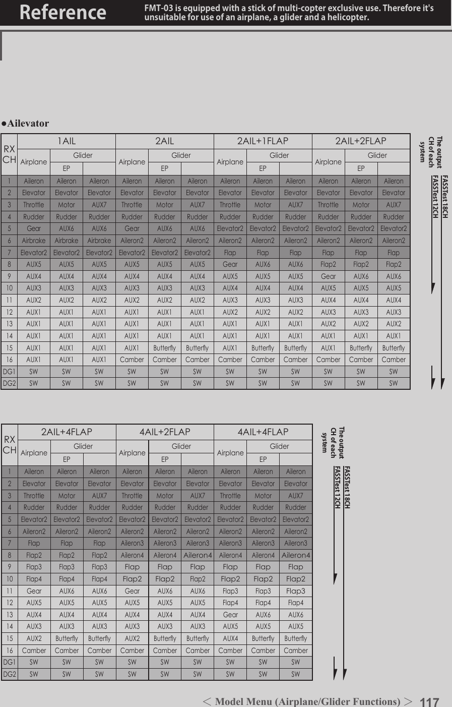
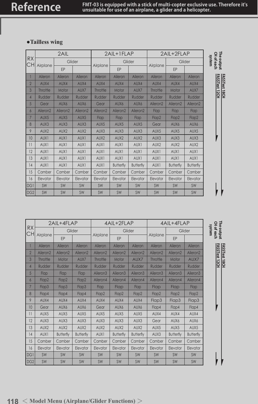
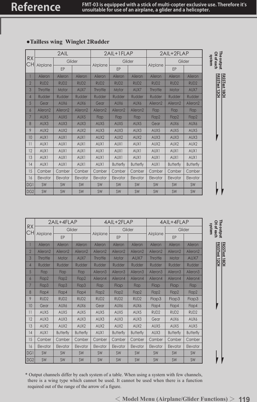
![114 <Model Menu (Airplane/Glider Functions) >Reference FMT-03 is equipped with a stick of multi-copter exclusive use. Therefore it's unsuitable for use of an airplane, a glider and a helicopter.●Selectthe[MODELMENU]andreturnto the homescreenbypushingtheRTNbuttonorpushingtheHome/Exitbutton.MODEL MENU (AIRPLANE/GLIDER FUNCTIONS)The dedicated mixes, etc. usable when airplane or glider model type is selected are displayed in this Model Menu functions section. First use the Model Type function of the Linkage Menu to preset the model type, wing type, and tail type matched to the fuselage used. Other settings reset the data used in mixing function, etc.These dedicated mixes can be set for each flight condition, as required. When you want to use the system by switching the settings for each condition by switch or stick position, use the Condition Select function to add ight conditions. (Up to 8 conditions can be used)Note:TheFMT-03isdesignedsothattheairplaneandglidermodeltypescanhandleaircraftofthesamewingtype.Thefunctionscommontoairplanesandgliders,exceptsomededicatedfunctions,aresummarizedwithoutregardtothemodeltype.Thesettingitemsaredifferent,dependingonthenumberofservos,etc.accordingtothewingtypeused.Thesetupscreensintheinstructionmanualaretypicalexamples.Model Menu functions listAIL DIFFERENTIALThis function adjusts the left and right ailerons. Roll axis correction and ne tuning with a VR are also possible. This is convenient when making settings during ight.[Airplane/glider, 2 ailerons or more]FLAP SETTINGThe aps can be adjusted independently. For a 4 aps model, the camber aps can be mixed with the brake aps. [Airplane/glider, 2 aps or more]AIL to CAMBERFLPThis mix operates the camber flaps in the aileron mode. It improves the operation characteristic of the roll axis. [Airplane/glider, 2 ailerons + 2 aps or more]AIL to BRAKEFLPThis mix operates the brake aps in the aileron mode. It improves the operation characteristic of the roll axis. [Airplane/glider, 4 aps or more]AIL to RUDThis mix is used when you want to operate the rudder at aileron operation. Banking at a shallow bank angle is possible. [Airplane/glider, general]AIRBRAKE to ELEThis mix is used to correct operation of the airbrakes (spoilers) when landing. [Airplane/glider, general](Model Menu screen example)*The Model Menu screen depends on the model type. This screen is for model type 4AIL+4FLP.●Selectthe [MODEL] atthehomescreenandcallthemodelmenushownbelowbypushingtheRTNbutton.●UsetheeditdialtoselectthefunctionyouwanttosetandcallthesetupscreenbypushingtheRTNbutton.S1<Editdial>●PushtheS1 buttontocallnextpage. Scrolling●Movingcursor](https://usermanual.wiki/Futaba/FMT-03-24G.User-Manual-Part-II/User-Guide-3285340-Page-34.png)
![115<Model Menu (Airplane/Glider Functions) >Reference FMT-03 is equipped with a stick of multi-copter exclusive use. Therefore it's unsuitable for use of an airplane, a glider and a helicopter.AIL 3(Chip Aileron) AIL 4(Chip Aileron)AIL1(Main Aileron) AIL 2(Main Aileron)FLP 2(Camber Flap)FLP 1(Camber Flap)ELEVATOR(ELEVATOR 2)V-TAIL AILVATORFLP 3AIR BRAKE(Brake Flap)FLP 4(Brake Flap) RUDDER 2 WingletRUDDER 1RUDDER (RUDDER 2) Wingletat Flying wing at Flying wing( ) ( )ELEVATOR ELEVATOR 2(AILERON 5)(AILERON 6)RUD to AILThis mix is used to correct roll maneuvers, knife edge, etc. of stunt planes. [Airplane/glider, general]CAMBER MixThis mix adjusts the camber and corrects the elevators. [Airplane/glider, 2 ailerons or more]ELE to CAMBERThis mix is used when you want to the mix camber aps with elevator operation. Lifting force can be increased at elevators up. [Airplane/glider, 2 ailerons or more]CAMBERFLP to ELEThis mix is used to correct for attitude changes when the camber aps are being used. [Airplane/glider, 2 ailerons + 1 ap or more]BUTTERFLY (Crow)This function is used when powerful brake operation is necessary. [Glider, 2 ailerons or more]TRIM MIX 1/2The ailerons, elevators, and flaps trim offset rate can be called by switch or condition selection. [Glider, 2 ailerons or more]AIRBRAKEThis function is used when airbrakes are necessary when landing or when diving, etc. during ight. (Airplane, general)GYROThis is a dedicated mix when a GYA Series gyro is used. [Airplane/glider, general]V-TAILThis function adjusts the elevators and rudder of V-tail models. [Airplane/glider, V-tail specications]AILEVATORThis function adjusts the elevators and ailerons of models with elevator specications. [Airplane/glider, elevator specications]WINGLETThis function adjusts the left and right rudders of winglet models. [Airplane/glider, winglet specications]MOTORThe operation speed when the motor of F5B and other EP gliders is started by switch can be set. [EP glider, general]RUD to ELEThis function is used to correct roll maneuvers, knife edge, etc. of stunt planes. [Airplane, general]SNAP ROLLThis function selects the snap roll switch and adjusts the steering angle of each rudder. Servo speed can also be adjusted. [Airplane general]](https://usermanual.wiki/Futaba/FMT-03-24G.User-Manual-Part-II/User-Guide-3285340-Page-35.png)
![120 <Model Menu (Airplane/Glider Functions) >Reference FMT-03 is equipped with a stick of multi-copter exclusive use. Therefore it's unsuitable for use of an airplane, a glider and a helicopter.S1●SelectthefunctionnameandreturntotheprecedingscreenbypushingtheRTNbuttonorpushingtheHome/Exitbutton.<Editdial>AIL 3(Chip Aileron) AIL 4(Chip Aileron)AIL1(Main Aileron) AIL 2(Main Aileron)AIL DIFF. [Airplane/glider,2aileronsormore]The left and right aileron differential can be adjusted independently. The differential rate can also be adjusted according to the flying state by setting a ne tuning VR.●CallstheAFR screendirectlywhenadjustingaileronoperationAFR.●FinetuningVRsetting*The graph is operated by setting a VR, etc.●Group/singlemodeswitching(For more information, refer to the description at the back of this manual.)●Aileronleft/rightadjustment<Wing type: 4 ailerons screen>*The display screen is an example. The actual screen depends on the Model Type.●OveralladjustmentbyRateAandRateB.Setting method●Movethecursortotheaileron(AIL)1~4left(orright)settingitemandpushtheRTNbuttontoswitchtothedatainputmode. Adjusttheaileronangleswhenthestickismovedtotheleft(orright)end. PushtheRTNbuttontoendadjustmentandreturntothecursormovemode.*The aileron AFR screen can be directly called from the AIL differential setup screen. ([AIL-AFR] )●WhensettingthefinetuningVR,movethecursortothe"--"itemandpushtheRTNbuttontocalltheselectionscreen,andthenselectthenetuningVR. PushtheRTNbuttontoendadjustmentandreturntothecursormovemode.●Thenetuningratecanbesetbycurve.(Currently selected condition name)●Select[AILDIFF.]atthemodelmenuandcallthesetupscreenshown below by pushingtheRTNbutton.Scrolling●Movingcursor●Selectingmode●Adjustingvalue](https://usermanual.wiki/Futaba/FMT-03-24G.User-Manual-Part-II/User-Guide-3285340-Page-40.png)
![121<Model Menu (Airplane/Glider Functions) >Reference FMT-03 is equipped with a stick of multi-copter exclusive use. Therefore it's unsuitable for use of an airplane, a glider and a helicopter.S1●SelectthefunctionnameandreturntotheprecedingscreenbypushingtheRTNbuttonorpushingtheHome/Exitbutton.<Editdial>FLP 2(Camber Flap)FLP 1(Camber Flap)FLP 3(Brake Flap) FLP 4(Brake Flap)FLAP SETTING [Correspondingmodeltype]:Airplane/glider,2apsormore]The up/down travel of each flap (camber flaps: FLP1/2, brake flaps: FLP3/4) can be adjusted independently at each servo according to the wing type.●TheoperationreferencepointofeachapcanbeoffsetThe camber aps of a 4-ap model can be mixed with the brake aps. (Brake FLP to camber FLP)●AnON/OFFswitchcanbeset. <Wing type: 4 aps screen>*The display screen is an example. The actual screen depends on the model type.Setting method●Movethecursortotheflap(FLP)1~4upordownitemaccordingtothewingtypeandpushtheRTNbuttontoswitchtothedatainputmode. Adjustthetravelindependently.●Tooffsettheoperationreferencepointofeachflap,movethecursortothecorrespondingoffsetitem.Usetheeditdialtooffsetthereferencepoint. PushtheRTNbuttontoendadjustmentandreturntothecursormovemode.●Operationreferencepointoffset●Upside/Downsideadjustment●Group/singlemodeswitching(For more information, refer to the description at the back of this manual.)●WhenusingbrakeFLPtocamberFLPmixing,movethecursortothe[ACT/INH]itemandturntheeditdialtotheleftandpushtheRTNbutton.(ONisdisplayed.) Whensettingaswitch,movethecursortothe[--]itemoftheswitchandpushtheRTNbuttontocalltheselectionscreen,andthenselecttheswitchandsetitsONdirection.(AlwaysONat"--"setting) (Foradescriptionoftheswitchselectionmethod,seethedescriptionatthebackofthismanual.)(CAMBERFLPsettingscreen)(BRAKEFLPsettingscreen)(B.FLPtoC.FLPsettingscreen)●Select[FLAPSETTING]atthemodelmenuandcallthesetupscreenshownbelowbypushingtheRTNbutton.Scrolling●Movingcursor●Selectingmode●Adjustingvalue●PushtheS1 buttontocallnextpage.](https://usermanual.wiki/Futaba/FMT-03-24G.User-Manual-Part-II/User-Guide-3285340-Page-41.png)
![122 <Model Menu (Airplane/Glider Functions) >Reference FMT-03 is equipped with a stick of multi-copter exclusive use. Therefore it's unsuitable for use of an airplane, a glider and a helicopter.S1●SelectthefunctionnameandreturntotheprecedingscreenbypushingtheRTNbuttonorpushingtheHome/Exitbutton.<Editdial>AIL 3(Chip Aileron) AIL 4(Chip Aileron)AIL1(Main Aileron) AIL 2(Main Aileron)FLP 2(Camber Flap)FLP 1(Camber Flap)AIL to CAMB.FLP [Correspondingmodeltype]:Airplane/glider,2ailerons+2apsormoreThis mix operates the camber flaps (FLP1/2) in the aileron mode. When the aileron stick is manipulated, the ailerons and camber flaps perform aileron operation simultaneously and the operation characteristic of the roll axis is improved.●Theaileronleft/rightmixingrateofeachapservocanbene-tuned.●Amixingcurvecanbeset.●AnON/OFFswitchcanbeset.●Linkingispossible:Linkthismixtoothermixes.●Mixingcurvesetting*For a description of the curve setting method, see the description at the back of this manual.●Adjustmentofeachapservo●Left/rightoveralladjustmentatRateAandRateBSetting method●MovethecursortotheACT/INHitemandpushtheRTNbuttontoswitchtothedatainputmode. TurntheeditdialtotheleftandpushtheRTNbutton.(ONisdisplayed.)●Whensettingaswitch,movethecursortothe[--]itemoftheswitchandpushtheRTNbuttontocalltheselectionscreen,andthenselecttheswitchandsetitsONdirection.(AlwaysONat"--"setting) (Foradescriptionoftheswitchselectionmethod,seethedescriptionatthebackofthismanual.)●MovethecursortotheleftorrightitemofeachapservoandpushtheRTNbuttontoswitchtothedatainputmode. Adjustthemixingratewiththeeditdial. PushtheRTNbuttontoendadjustmentandreturntothecursormovemode.*When the mixing direction is reversed by the linkage, adjustments can be made by changing the mixing rate polarity (+ or -).●Amixingcurvecanbeset. (Foradescriptionofthemixingcurvesettingmethod,seethedescriptionatthebackofthismanual.)●Tosetlinking,movethecursortothe[LINK]itemandpushtheRTNbuttontoswitchtothedatainputmode. SetittoONandpushtheRTNbutton.(Currently selected condition name)●Select[AILtoCAMB.FLP]atthemodelmenuandcallthesetupscreenshownbelowbypushingtheRTNbutton.●Group/singlemodeswitching(For more information, refer to the description at the back of this manual.)*The display screen is an example. The actual screen depends on the model type.Scrolling●Movingcursor●Selectingmode●Adjustingvalue●PushtheS1 buttontocallnextpage.](https://usermanual.wiki/Futaba/FMT-03-24G.User-Manual-Part-II/User-Guide-3285340-Page-42.png)
![123<Model Menu (Airplane/Glider Functions) >Reference FMT-03 is equipped with a stick of multi-copter exclusive use. Therefore it's unsuitable for use of an airplane, a glider and a helicopter.S1●SelectthefunctionnameandreturntotheprecedingscreenbypushingtheRTNbuttonorpushingtheHome/Exitbutton.<Editdial>AIL 3(Chip Aileron) AIL 4(Chip Aileron)AIL1(Main Aileron) AIL 2(Main Aileron)FLP 3(Brake Flap) FLP 4(Brake Flap)AIL to BRAKEFLP [Correspondingmodeltype]:Airplane/glider,4apsormoreThis mix operates the brake flaps (FLP3/4) in the aileron mode. When the aileron stick is manipulated, the aileron and brake flaps perform the aileron operation simultaneously and the operation characteristic of the roll axis is improved.●Theaileronleftandrightmixingratescanbeadjustedforeachapservo.●Amixingcurvecanbeset.●MixingduringightcanbeturnedON/OFFbysettingaswitch.(AlwaysONat[--]setting)●Linkingcanbeset:Linkthismixtoothermixes.●Setting method●MovethecursortotheACT/INHitemandpushtheRTNbuttontoswitchtothedatainputmode. TurntheeditdialtotheleftandpushtheRTNbutton.(ONisdisplayed.)●Whensettingaswitch,movethecursortothe[--]itemoftheswitchandpushtheRTNbuttontocalltheselectionscreen,andthenselecttheswitchandsetitsONdirection.(AlwaysONat"--"setting) (Foradescriptionoftheswitchselectionmethod,seethedescriptionatthebackofthismanual.)●MovethecursortotheleftorrightbuttonofeachapservoandpushtheRTNbuttontoswitchtothedatainputmode. Adjustthemixingratewiththeeditdial. PushtheRTNbuttontoendadjustmentandreturntothecursormovemode.*When the mixing direction is reversed by the linkage, adjustments can be made by reversing the mixing rate polarity (+ or -).●Amixingcurvecanbeset. (Foradescriptionofthecurvesettingmethod,seethedescriptionatthebackofthismanual.)●Tosetlinking,movethecursortotheLinkitemandpushtheRTNbuttontoswitchtothedatainputmode. SetittoONandpushtheRTNbutton.●Mixingcurvesetting*For a description of the curve setting method, see the description at the back of this manual.●Adjustmentofeachapservo●Left/rightoveralladjustmentatRateAandRateB(Currently selected condition name)●Select[AILtoBRAKEFLP]atthemodelmenuandcallthesetupscreenshownbelowbypushingtheRTNbutton.●Group/singlemodeswitching(For more information, refer to the description at the back of this manual.)*The display screen is an example. The actual screen depends on the model type.Scrolling●Movingcursor●Selectingmode●Adjustingvalue●PushtheS1 buttontocallnextpage.](https://usermanual.wiki/Futaba/FMT-03-24G.User-Manual-Part-II/User-Guide-3285340-Page-43.png)
![124 <Model Menu (Airplane/Glider Functions) >Reference FMT-03 is equipped with a stick of multi-copter exclusive use. Therefore it's unsuitable for use of an airplane, a glider and a helicopter.S1●SelectthefunctionnameandreturntotheprecedingscreenbypushingtheRTNbuttonorpushingtheHome/Exitbutton.<Editdial>RUDDER 2RUDDER RUDDERV-TAILRUDDER 2WingletRUDDER 1Wingletat Flying wing at Flying wing( ) ( )AIL 3 AIL 3(Chip Aileron) (Chip Aileron)AIL1(Main Aileron) AIL 2(Main Aileron)AIL to RUD [Correspondingmodeltype]:Airplane/glider,generalUse this mix when you want to mix the rudders with aileron operation. ●Amixingcurvecanbeset.●MixingduringightcanbeturnedON/OFFbysettingaswitch.(AlwaysONat[--]setting)●Themixingratecanbene-tunedbysettingaVR.Setting method●MovethecursortotheACT/INHitemandpushtheRTNbuttontoswitchtothedatainputmode. TurntheeditdialtotheleftandpushtheRTNbutton.(ONisdisplayed.)●Whensettingaswitch,movethecursortothe[--]itemoftheswitchandpushtheRTNbuttontocalltheselectionscreen,andthenselecttheswitchandsetitsONdirection.(AlwaysONat"--"setting) (Foradescriptionoftheswitchselectionmethod,seethedescriptionatthebackofthismanual.●WhensettingaVR,movethecursortotheFineTuning"--"itemandpushtheRTNbuttontocalltheselectionscreen,andthenselecttheVR.Theadjustmentratecanbeset.TheVRoperationmodecanalsobeselected.[FinetuningVRoperationmode][LIN.] Mixingrate0%atcenterofVR.WhentheVRisturnedclockwiseandcounterclockwise,themixingrateincreasesanddecreases,respectively.[ATL+]Mixingrate0%atleftendofVR.WhentheVRisturned,themixingrateincreases.[ATL-] Mixingrate0%atrightendof VR.WhentheVRisturned,themixingrateincreases.[SYM.]WhentheVRisturnedtotheleftorrightoftheneutralposition,themixingrateincreases.●Mixingcurvesetting*For a description of the curve setting method, see the description at the back of this manual. ●Left/rightoveralladjustmentatRateAandRateB(Currently selected condition name)●Select[AILtoRUD]atthemodelmenuandcallthesetupscreenshownbelowbypushingtheRTNbutton.●Group/singlemodeswitching(For more information, refer to the description at the back of this manual.)*The display screen is an example. The actual screen depends on the model type.●FinetuningVRsetting●Adjustmentrate●Operationmode●Amixingcurvecanbeset. (Foradescriptionofthecurvesettingmethod,seethedescriptionatthebackofthismanual.)Scrolling●Movingcursor●Selectingmode●Adjustingvalue●PushtheS1 buttontocallnextpage.](https://usermanual.wiki/Futaba/FMT-03-24G.User-Manual-Part-II/User-Guide-3285340-Page-44.png)
![125<Model Menu (Airplane/Glider Functions) >Reference FMT-03 is equipped with a stick of multi-copter exclusive use. Therefore it's unsuitable for use of an airplane, a glider and a helicopter.S1●SelectthefunctionnameandreturntotheprecedingscreenbypushingtheRTNbuttonorpushingtheHome/Exitbutton.<Editdial>ELEVATOR ELEVATOR 2AILVATORAIR BRAKEV-TAILELEVATOR ELEVATOR 2AIRBRAKE to ELE [Correspondingmodeltype]:Airplane/glider,generalThis mix is used when you want to mix the elevators with airbrake (spoiler) operation. It raises the elevators to correct for dropping of the nose during airbrake operation.*This function does not operate when airbrake is not assigned at the Function menu in the Linkage Menu.●TheRate1side/Rate2sidemixingratewiththeelevatorservoscanbeadjusted.●Amixingcurvecanbeset.●MixingduringightcanbeturnedON/OFFbysettingaswitch.(AlwaysONat[--]setting)●Themixingratecanbene-tunedbysettingaVR.●FinetuningVRsetting●Group/singlemodeswitching(For more information, refer to the description at the back of this manual.)●OveralladjustmentbyRateAandRateB.(Currently selected condition name)●Select[AIRBRAKEtoELE]atthemodelmenuandcallthesetupscreen shown belowbypushingtheRTNbutton.●Mixingcurvesetting*For a description of the curve setting method, see the description at the back of this manual.●Adjustmentrate●Operationmode●Adjustmentofeachelevatorservo*The display screen is an example. The actual screen depends on the model type.Scrolling●Movingcursor●Selectingmode●Adjustingvalue●PushtheS1 buttontocallnextpage.](https://usermanual.wiki/Futaba/FMT-03-24G.User-Manual-Part-II/User-Guide-3285340-Page-45.png)
![126 <Model Menu (Airplane/Glider Functions) >Reference FMT-03 is equipped with a stick of multi-copter exclusive use. Therefore it's unsuitable for use of an airplane, a glider and a helicopter.Setting method●MovethecursortotheACT/INHitemandpushtheRTNbuttontoswitchtothedatainputmode. TurntheeditdialtotheleftandpushtheRTNbutton.(ONisdisplayed.)●Whensettingaswitch,movethecursortothe[--]itemoftheswitchandpushtheRTNbuttontocalltheselectionscreen,andthenselecttheswitchandsetitsONdirection.(AlwaysONat"--"setting) (Foradescriptionoftheswitchselectionmethod,seethedescriptionatthebackofthismanual.●WhensettingaVR,movethecursortotheFinetuning"--"itemandpushtheRTNbuttontocalltheselectionscreen,andthenselecttheVR.Theadjustmentratecanbeset.TheVRoperationmodecanalsobeset. (ForadescriptionofthenetuningVRsettingmethod,seethedescriptionatthebackofthismanual.)●Amixingcurvecanbeset. (Foradescriptionofthecurvesettingmethod,seethedescriptionatthebackofthismanual.)[FinetuningVRoperationmode][LIN.] Mixingrate0%atcenterofVR.WhentheVRisturnedclockwiseandcounterclockwise,themixingrateincreasesanddecreases,respectively.[ATL+]Mixingrate0%atleftendofVR.WhentheVRisturned,themixingrateincreases.[ATL-] Mixingrate0%atrightendof VR.WhentheVRisturned,themixingrateincreases.[SYM.]WhentheVRisturnedtotheleftorrightoftheneutralposition,themixingrateincreases.](https://usermanual.wiki/Futaba/FMT-03-24G.User-Manual-Part-II/User-Guide-3285340-Page-46.png)
![127<Model Menu (Airplane/Glider Functions) >Reference FMT-03 is equipped with a stick of multi-copter exclusive use. Therefore it's unsuitable for use of an airplane, a glider and a helicopter.S1●SelectthefunctionnameandreturntotheprecedingscreenbypushingtheRTNbuttonorpushingtheHome/Exitbutton.<Editdial>RUDDER 2RUDDER RUDDERV-TAILRUDDER 2WingletRUDDER 1Wingletat Flying wing at Flying wing( ) ( )AIL 3 AIL 3(Chip Aileron) (Chip Aileron)AIL1(Main Aileron) AIL 2(Main Aileron)RUD to AIL [Correspondingmodeltype]:Airplane/glider,generalThis function is used when you want to mix the ailerons with rudder operation. It is used when rudder is applied during roll maneuvers, knife edge, etc. of stunt planes. It can be used to bank scale models, large models, etc. like a full size plane.●Amixingcurvecanbeset.●MixingduringightcanbeturnedON/OFFbysettingaswitch.(AlwaysONat[--]setting)●Linkingcanbeset:Linkthismixtoothermixes.●Themixingratecanbene-tunebysettingaVR.Setting method●MovethecursortotheACT/INHitemandpushtheRTNbuttontoswitchtothedatainputmode. TurntheeditdialtotheleftandpushtheRTNbutton.(ONisdisplayed.)●Whensettingaswitch,movethecursortothe[--]itemoftheswitchandpushtheRTNbuttontocalltheselectionscreen,andthenselecttheswitchandsetitsONdirection.(AlwaysONat"--"setting) (Foradescriptionoftheswitchselectionmethod,seethedescriptionatthebackofthismanual.●WhensettingaVR,movethecursortotheFinetuning"--"itemandpushtheRTNbuttontocalltheselectionscreenandthenselecttheVR.Theadjustmentratecanbeset,.TheVRoperationmodecanalsobeset. (ForadescriptionofthenetuningVRsettingmethod,seethedescriptionatthebackofthismanual.)●Amixingcurvecanbeset. (Foradescriptionofthecurvesettingmethod,seethedescriptionatthebackofthismanual.)●Whenlinking:movethecursortothe[LINK]itemandpushtheRTNbuttontoswitchtothedatainputmode.TurntheeditdialtotheleftandpushtheRTNbutton.(ONisdisplayed.)●Mixingcurvesetting*For a description of the curve setting method, see the description at the back of this manual.●Left/rightoveralladjustmentatRateAandRateB(Currently selected condition name)●Select[RUDtoAIL]atthemodelmenuandcallthesetupscreenshownbelowbypushingtheRTNbutton.●Group/singlemodeswitching(For more information, refer to the description at the back of this manual.)*The display screen is an example. The actual screen depends on the model type.●FinetuningVRsetting●Adjustmentrate●Operationmode[FinetuningVRoperationmode][LIN.] Mixingrate0%atcenterofVR.WhentheVRisturnedclockwiseandcounterclockwise,themixingrateincreasesanddecreases,respectively.[ATL+]Mixingrate0%atleftendofVR.WhentheVRisturned,themixingrateincreases.[ATL-] Mixingrate0%atrightendof VR.WhentheVRisturned,themixingrateincreases.[SYM.]WhentheVRisturnedtotheleftorrightoftheneutralposition,themixingrateincreases.Scrolling●Movingcursor●Selectingmode●Adjustingvalue●PushtheS1 buttontocallnextpage.](https://usermanual.wiki/Futaba/FMT-03-24G.User-Manual-Part-II/User-Guide-3285340-Page-47.png)
![128 <Model Menu (Airplane/Glider Functions) >Reference FMT-03 is equipped with a stick of multi-copter exclusive use. Therefore it's unsuitable for use of an airplane, a glider and a helicopter.S1●SelectthefunctionnameandreturntotheprecedingscreenbypushingtheRTNbuttonorpushingtheHome/Exitbutton.<Editdial>CAMBER MIX [Correspondingmodeltype]:Airplane/glider,2aileronsormoreThis function adjusts the AFR (D/R) rate of camber operation which operates the wing camber (ailerons, camber flaps, brake flaps) in the negative and positive directions. The aileron, flap, and elevator rates can also be adjusted independently by curve, and attitude changes caused by camber operation can be corrected.*Initial setting assigns camber operation to side lever LS.●Theup/downsideratesoftheaileron,ap,andelevatorservoscanbeadjustedbycurve.Whenthemixingdirectionisreversedbythelinkage,adjustmentscanbemadebychangingthemixingratepolarity(+or-).●MixingduringightcanbeturnedON/OFFbysettingaswitch.(AlwaysONat[--]setting)●Adelaycanbesetforeachcondition.AcutswitchwhichcanturnOFFthedelayfunctioncanbeset.●Thespeedoftheaileron,ap,andelevatorservoscanbeset.(INside/OUTside)●Conditiondelaycutswitch●Conditiondelaysetting●CamberAFR(D/R)setupscreencall(For a description of the setting method, refer to the AFR function.)●Servospeedsetting(For a description of the setting method, see the description at the back of this manual.)●OveralladjustmentbyRateAandRateB●Aileronrateadjustment(Currently selected condition name)●Select[CAMBERMIX]atthemodelmenuandcallthesetupscreenshownbelowbypushingtheRTNbutton.●Mixingcurvesetting*For a description of the curve setting method, see the description at the back of this manual.*The display screen is an example. The actual screen depends on the model type.(Curve/ratesettingscreen)Scrolling●Movingcursor●Selectingmode●Adjustingvalue●PushtheS1 buttontocallnextpage.](https://usermanual.wiki/Futaba/FMT-03-24G.User-Manual-Part-II/User-Guide-3285340-Page-48.png)
![129<Model Menu (Airplane/Glider Functions) >Reference FMT-03 is equipped with a stick of multi-copter exclusive use. Therefore it's unsuitable for use of an airplane, a glider and a helicopter.AIL 3(Chip Aileron) AIL 4(Chip Aileron)AIL1(Main Aileron) AIL 2(Main Aileron)FLP 2(Camber Flap)FLP 1(Camber Flap)ELEVATOR ELEVATOR 2V-TAILELEVATOR ELEVATOR 2AILVATORFLP 3(Brake Flap) FLP 4(Brake Flap)Setting method●MovethecursortotheACT/INHitemandpushtheRTNbuttontoswitchtothedatainputmode. TurntheeditdialtotheleftandpushtheRTNbutton.(ONisdisplayed.)●Whensettingaswitch,movethecursortothe[--]itemoftheswitchandpushtheRTNbuttontocalltheselectionscreen,andthenselecttheswitchandsetitsONdirection.(AlwaysONat"--"setting) (Foradescriptionoftheswitchselectionmethod,seethedescriptionatthebackofthismanual.)●Whensettingaconditiondelay,movethecursortothe[COND.DELAY]itemandpushtheRTNbuttontoswitchtothedatainputmode. Setthedelaywiththeeditdial. PushtheRTNbuttontoendadjustmentandreturntothecursormovemode. Whensettingacutswitch,movethecursorto[CUT-SW]itemandpushtheRTNbuttontocalltheselectionscreen,andthenselecttheswitchandsetitsONdirection.(AlwaysONat[--]setting) (Foradescriptionoftheconditiondelayfunction,seethedescription atthebackofthismanual.)●CamberAFR(D/R)screencall MovethecursortotheCamberAFRitemandpushtheRTNbuttontocallthesetupscreen.(Foradescriptionofthesetupmethod,seethedescriptionatthebackofthismanual.)(Curve/ratesetupscreen)●Thecurveandrateareadjustedbycallingtheaileron,flap,andelevatorcurve/ratescreens. Therateandcurveofeachservocanbesetbycallingeachscreen.(Foradescriptionofthecurvesettingmethod,seethedescriptionatthebackofthismanual.) Theservospeedcanalsobeadjusted.](https://usermanual.wiki/Futaba/FMT-03-24G.User-Manual-Part-II/User-Guide-3285340-Page-49.png)
![130 <Model Menu (Airplane/Glider Functions) >Reference FMT-03 is equipped with a stick of multi-copter exclusive use. Therefore it's unsuitable for use of an airplane, a glider and a helicopter.S1●SelectthefunctionnameandreturntotheprecedingscreenbypushingtheRTNbuttonorpushingtheHome/Exitbutton.<Editdial>ELE to CAMBER [Correspondingmodeltype]:Airplane/glider,2aileronsormoreThis function is used when you want to mix the camber aps with elevator operation. When used, the aps are lowered by up elevator, and lift can be increased.Note: Tailless wing elevator can be operated when this mix is activated.●Amixingcurvecanbeset.●MixingduringightcanbeturnedON/OFFbysettingaswitch.(AlwaysONat[--]setting)●Themixingratecanbene-tunedbysettingaVR.●Aileronsandapsrateadjustment1. SelecttherateboxandpushtheRTNbuttontoswitchtothedatainputmode.2. Adjusttheratesbyscrollingtheeditdial.3. PushtheRTNbuttontoendadjustmentandreturn to thecursormovemode.Setting method●MovethecursortotheACT/INHitemandpushtheRTNbuttontoswitchtothedatainputmode. TurntheeditdialtotheleftandpushtheRTNbutton.(ONisdisplayed.)●Whensettingaswitch,movethecursortothe[--]itemoftheswitchandpushtheRTNbuttontocalltheselectionscreen,andthenselecttheswitchandsetitsONdirection.(AlwaysONat"--"setting) (Foradescriptionoftheswitchselectionmethod,seethedescriptionatthebackofthismanual.)●WhensettingaVR,movethecursortotheFinetuning"--"itemandpushtheRTNbuttontocalltheselectionscreen,andthenselecttheVR.Theadjustmentratecanbeset. TheVRoperationmodecanalsobeselected.●Amixingcurvecanalsobeset. (Foradescriptionofthecurvesettingmethod,seethedescriptionatthebackofthismanual.)●Group/singlemodeswitching(For more information, refer to the description at the back of this manual.)●OveralladjustmentbyRateAandRateB.(Currently selected condition name)●Select[ELEtoCAMBER] at the modelmenuandcallthesetupscreenshownbelowbypushingtheRTNbutton.●Mixingcurvesetting*For a description of the curve setting method, see the description at the back of this manual.*The display screen is an example. The actual screen depends on the model type.●FinetuningVRsetting●Adjustmentrate●OperationmodeScrolling●Movingcursor●Selectingmode●Adjustingvalue●PushtheS1 buttontocallnextpage.](https://usermanual.wiki/Futaba/FMT-03-24G.User-Manual-Part-II/User-Guide-3285340-Page-50.png)
![131<Model Menu (Airplane/Glider Functions) >Reference FMT-03 is equipped with a stick of multi-copter exclusive use. Therefore it's unsuitable for use of an airplane, a glider and a helicopter.S1●SelectthefunctionnameandreturntotheprecedingscreenbypushingtheRTNbuttonorpushingtheHome/Exitbutton.<Editdial>ELEVATOR ELEVATOR 2V-TAILELEVATOR ELEVATOR 2AILVATORFLP 2(Camber Flap)FLP 1(Camber Flap)CAMB.FLP to ELE [Correspondingmodeltype]:Airplane/glider, 2ailerons+1apormoreThis mixing is used to correct changes (elevator direction) generated when the camber aps (speed aps) are used.●Theelevatorservosupside/downsideratecanbeadjusted.Whenthemixingdirectionisreversedbythelinkage,adjustmentscanbemadebychangingthemixingratepolarity(+or–).●Amixingcurvecanbeset.●MixingduringightcanbeturnedON/OFFbysettingaswitch.(AlwaysONat[--]setting)●Themixingratecanbene-tunedbysettingaVR.●ElevatorrateadjustmentSetting method●MovethecursortotheACT/INHitemandpushtheRTNbuttontoswitchtothedatainputmode. TurntheeditdialtotheleftandpushtheRTNbutton.(ONisdisplayed.)●Whensettingaswitch,movethecursortothe[--]itemoftheswitchandpushtheRTNbuttontocalltheselectionscreen,andthenselecttheswitchandsetitsONdirection.(AlwaysONat"--"setting) (Foradescriptionoftheswitchselectionmethod,seethedescriptionatthebackofthismanual.●MovethecursortotheelevatorservosleftandrightitemandpushtheRTNbuttontoswitchtothedatainputmode.Adjustthemixingratewiththeeditdial. PushtheRTNbuttontoendadjustmentandreturntothecursormovemode.*When the mixing direction is reversed by the linkage, adjustments can be made by changing the mixing rate polarity (+ or –).●WhensettingaVR,movethecursortotheFinetuning"--"itemandpushtheRTNbuttontocalltheselectionscreen,andthenselecttheVR.TheVRoperationmodecanbeselected.●Amixingcurvecanbeset. (Foradescriptionofthecurvesettingmethod,seethedescriptionatthebackofthismanual.)●OveralladjustmentbyRateAandRateB.(Currently selected condition name)●Select[CAMB.FLPtoELE] at the model menu andcallthesetupscreenshownbelowbypushingtheRTNbutton.●Mixingcurvesetting*For a description of the curve setting method, see the description at the back of this manual.*The display screen is an example. The actual screen depends on the model type.●FinetuningVRsetting●Adjustmentrate●Operationmode●Group/singlemodeswitching(For more information, refer to the description at the back of this manual.)Scrolling●Movingcursor●Selectingmode●Adjustingvalue●PushtheS1 buttontocallnextpage.](https://usermanual.wiki/Futaba/FMT-03-24G.User-Manual-Part-II/User-Guide-3285340-Page-51.png)
![132 <Model Menu (Airplane/Glider Functions) >Reference FMT-03 is equipped with a stick of multi-copter exclusive use. Therefore it's unsuitable for use of an airplane, a glider and a helicopter.S1●SelectthefunctionnameandreturntotheprecedingscreenbypushingtheRTNbuttonorpushingtheHome/Exitbutton.<Editdial>BUTTERFLY [Correspondingmodeltype]:Glider,2aileronsormoreThis function allows powerful brake operation by simultaneously raising the left and right ailerons and lowering the flaps (camber flap, brake ap).This setting will allow the ailerons to be raised while the flaps are simultaneously lowered. Butterfly (crow) produces an extremely efficient landing configuration by accomplishing the following: 1.Slowtheaircraft’svelocity.2.Providewashoutatthewingtipstoreducethetendencytotipstall.3.Createmorelifttowardthecenterofthewingallowingittoyataslowerspeed●MixingduringightcanbeturnedON/OFFbysettingaswitch.(AlwaysONat[--]setting)●Thebutteryoperationreferencepointcanbeoffset.WhentheRTNbuttonispushedwiththeoffsetitemselectedwhenoperatedtothepositiontobechanged,thereferencepointisoffset.Ifthereferencepointisoffsettoomuch,unexpectedoperationmaybeperformed.●Theaileronsandapsoperationspeedcanbeadjusted.(INside/OUTside)●Adelaycanbesetforeachcondition.AcutswitchwhichcanturnOFFthedelayfunctioncanalsobeset.●Thedifferentialratecanbeadjusted.*When servo binding occurs when setting the ailerons and aps in buttery mixing, use the AFR function to adjust the rudder angle.●Whenoffsettingthebutterflyoperationreferencepoint,operatetothepointyouwanttochangeandthenpresstheEDITbuttonfor1second."INITIALIZEELEVATORCURVE?"isdisplayed.PleasechoosewhethertoinitializebyYES,ornottoinitializebyNO.●Differentialrateadjustment●Toelevatorcorrectionsetupscreen●CallstheButteryAFR(D/R)setupscreen(For a description of the setting method, see the description at the back of this manual.)●Aileronandapservosspeedsetting(For a description of the setting method, see the description at the back of this manual.)●Conditiondelaysetting andcutswitchsetting(For a description of the setting method, see the description at the back of this manual.)● Select the Mixing RateAIL and FLPbox andpushtheRTNbuttontoswitchtothedatainputmode.Adjustthemixingrates. PushtheRTNbutton to endadjustmentandreturntothecursormovemode.(Currently selected condition name)●Select[BUTTERFLY]atthemodelmenuandcallthesetupscreenshownbelowbypushingtheRTNbutton.*The display screen is an example. The actual screen depends on the model type.●Whenusingthis function,movethecursortothe[ACT/INH]itemandpushtheRTNbuttontoswitchtothedatainputmode.TurntheeditdialtotheleftandpushtheRTNbutton.(ONisdisplayed.)●Group/singlemodeswitching(For more information, see the description at the back of this manual.)●Whensettingaswitch,selecttheSWITCH[--]boxandpushtheRTNbuttontoswitchtothedatainputmode.PresstheEDITbuttontocalltheselectionscreen,andthenselecttheswitchandsetitsONdirection.Scrolling●Movingcursor●Adjustingvalue●PushtheS1 buttontocallnextpage.](https://usermanual.wiki/Futaba/FMT-03-24G.User-Manual-Part-II/User-Guide-3285340-Page-52.png)
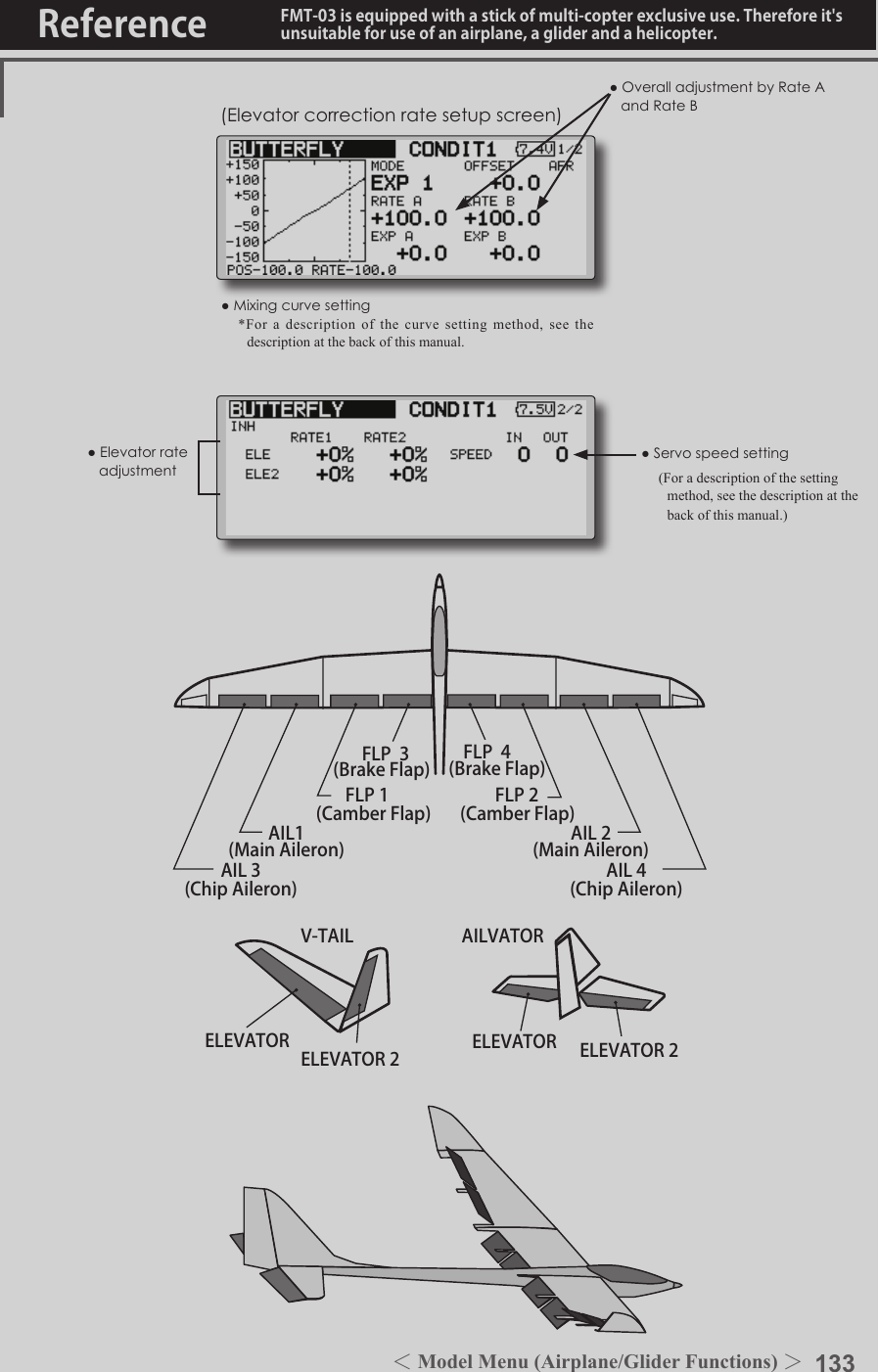
![134 <Model Menu (Airplane/Glider Functions) >Reference FMT-03 is equipped with a stick of multi-copter exclusive use. Therefore it's unsuitable for use of an airplane, a glider and a helicopter.S1●SelectthefunctionnameandreturntotheprecedingscreenbypushingtheRTNbuttonorpushingtheHome/Exitbutton.<Editdial>TRIM MIX 1/2 [Correspondingmodeltype]:Glider,2aileronsormoreThese functions call the ailerons, elevators, and aps (camber aps, brake aps) trim offset rates preset according to the ight state. The amount of ailerons, elevator, and flaps (camber ap, brake ap) trim offset can be set to a switch.As an example Trim Mix 1 can be set up for launching, with speed aps and ailerons dropped, and a slight amount of up elevator. Trim mix 2 can be used for high speed flying, with both ailerons and speed aps reexed slightly, and a bit of down elevator. The trim functions can be activated during ight by setting a switch. To prevent sudden trim changes when switching ight conditions, a delay can be set to provide a smooth transition between the two. Trim Mix 2 will have priority over Trim Mix 1.●WhenanetuningVRissetonthenextpage,theaileronsapsandelevatorstrimratescanbeadjusted. MovethecursortothecorrespondingsettingitemandpushtheRTNbuttontoswitchtothedatainputmode.adjusttheratewiththeeditdial. PushtheRTNbuttontoendadjustmentandreturntothecursormovemode.●Theailerons,aps,andelevatorsoffsetratecanbeadjusted. MovethecursortothecorrespondingsettingitemandpushtheRTNbuttontoswitchtothedatainput mode. Adjusttheratewiththeeditdial. PushtheRTNbutton to endadjustmentand returntothecursormovemode.Example1.MovetotheACT/INHitemandpushtheRTNbuttontoswitchtothedatainputmode.Setthetrimmixfunctionto[ON].*When separating the settings for each condition, move to the [GROUP] item and set it to [Single].2.SelecttheON/OFFswitch.3.Selectthe[Manual]or[Auto]mode. Inthe[Auto]mode,alsoselectanautoSW.Thisswitchcanbelinkedtoastick,etc.<Speed> In:TheoperationspeedatswitchONcanbeset. Out:ThereturnspeedatswitchOFFcanbeset.<FineTuning> TheoffsetratecanbevariedintheFineTuningnumericrangesetatscreen[5/5]by VR,etc.selection.<ConditionDelay> Whenightconditionsareset,theoperationspeedcanbesetforeachcondition.Conditiondelayoperationcanbeinterruptedandeachrudderquicklyreturnedtoitsoriginalpositionbyselectingacutswitch.(Currently selected condition name)●Select[TRIMMIX1or2]atthemodelmenuandcallthesetupscreenshownbelowbypushingtheRTNbutton.*The display screen is an example. The actual screen depends on the model type.Scrolling●Movingcursor●Adjustingvalue●PushtheS1 buttontocallnextpage.](https://usermanual.wiki/Futaba/FMT-03-24G.User-Manual-Part-II/User-Guide-3285340-Page-54.png)
![135<Model Menu (Airplane/Glider Functions) >Reference FMT-03 is equipped with a stick of multi-copter exclusive use. Therefore it's unsuitable for use of an airplane, a glider and a helicopter.●Whenusingthisfunction,movethecursortothe[ACT/INH]itemandpushtheRTNbuttontoswitchtothedatainputmode.Turntheeditdialtothe left andpushtheRTNbutton.(ONisdisplayed.)●Group/singlemodeswitching(For more information, see the description at the back of this manual.)●WhenusingafinetuningVR,movethe cursortothisitemand push theRTNbuttontocalltheselectionscreen. SelecttheVRandpushtheRTNbutton.●Conditiondelaysetting(foradescriptionofthesettingmethod,seethedescriptionatthebackofthismanual)andcutswitchsetting.●Ailerons,flaps,anelevatorsservospeedsetting(For a description of the setting method, see the description at the back of this manual.)●Manual/AutomodeselectionManual:SwitchesthefunctionON/OFFbyswitchAuto:Trimmixfunctioncallcanbelinkedtoastick,etc.Astickswitch,etc.separatefromthefunctionON/OFFswitchisset.AIL 3(Chip Aileron) AIL 4(Chip Aileron)AIL1(Main Aileron) AIL 2(Main Aileron)FLP 2(Camber Flap)FLP 1(Camber Flap)ELEVATOR ELEVATOR 2V-TAILELEVATOR ELEVATOR 2AILVATORFLP 3(Brake Flap) FLP 4(Brake Flap)](https://usermanual.wiki/Futaba/FMT-03-24G.User-Manual-Part-II/User-Guide-3285340-Page-55.png)
![136 <Model Menu (Airplane/Glider Functions) >Reference FMT-03 is equipped with a stick of multi-copter exclusive use. Therefore it's unsuitable for use of an airplane, a glider and a helicopter.S1●SelectthefunctionnameandreturntotheprecedingscreenbypushingtheRTNbuttonorpushingtheHome/Exitbutton.<Editdial>AIRBRAKE [Correspondingmodeltype]:Airplane,generalThis function is used when an air brake is necessary when landing or diving, etc.The preset elevators and flaps (camber flap, brake flap) offset amount can be activated by a switch.The offset amount of the aileron, elevator, and flap servos can be adjusted as needed. Also the speed of the aileron, elevator, and ap servos can be adjusted. (IN side/OUT side) A delay can be set for each condition, and a Cut switch which will turn OFF the delay can be chosen. Trim amounts can be fine-tuned by setting a VR You can also set the Auto Mode, which will link Airbrake to a stick, switch, or dial. A separate stick switch or dial can also be set as the ON/OFF switch.Setting example for F3A and other aperon specications(When2aileronsmodeltypeselected)Offsetrate: AIL:[-35~-45%],AIL2:[-35~-45%],ELE:[+5~7%]Note: The input numerics are examples. Adjust the travel to match the aircraft.Modesetting: ACT:[ON] Group:[Single] Switch:[SW-C] Mode:[Manual]●WhenanetuningVRissetonthenextpage,theailerons',aps',andelevators'trimratescanbeadjusted. Movethecursor to thecorrespondingsettingitemandpushtheRTNbuttontoswitchtothedatainputmode.Adjusttheratewiththeeditdial. PushtheRTNbuttontoendadjustmentandreturntothecursormovemode.●Theailerons,aps,andelevatorsoffsetratecanbeadjusted. Movethecursor to thecorrespondingsettingitemandpushthe RTNbuttontoswitchtothedatainputmode.Adjusttheratewiththeeditdial. PushtheRTNbuttonto endadjustmentandreturntothecursormovemode.(Currently selected condition name)●Select[AIRBRAKE] atthemodelmenuandcallthesetupscreenshownbelowbypushingtheRTNbutton.*The display screen is an example. The actual screen depends on the model type.Scrolling●Movingcursor●Adjustingvalue●PushtheS1 buttontocallnextpage.](https://usermanual.wiki/Futaba/FMT-03-24G.User-Manual-Part-II/User-Guide-3285340-Page-56.png)
![137<Model Menu (Airplane/Glider Functions) >Reference FMT-03 is equipped with a stick of multi-copter exclusive use. Therefore it's unsuitable for use of an airplane, a glider and a helicopter.●Whenusingthisfunction,movethecursortothe[ACT/INH]itemand turn the editdialtotheleftandpushtheRTNbutton.(ONisdisplayed.)●Group/singlemodeswitching(For more information, see the description at the back of this manual.)●WhenusingafinetuningVR,movethecursortothissettingitemandpresstheEDITbuttontocalltheselectionscreen. SelecttheVRandpushtheRTNbutton.●Conditiondelaysetting(foradescriptionofthesettingmethod,seethedescriptionatthebackofthismanual)andcutswitchsetting.●Ailerons,flaps,anelevatorsservospeedsetting(For a description of the setting method, see the description at the back of this manual.)●Manual/AutomodeselectionManual:SwitchesthefunctionON/OFFbyswitchAuto:Trimmixfunctioncallcanbelinkedtoastick,etc.Astickswitch,etc.separatefromthefunctionON/OFFswitchisset.AIL 3(Chip Aileron) AIL 4(Chip Aileron)AIL1(Main Aileron) AIL 2(Main Aileron)FLP 2(Camber Flap)FLP 1(Camber Flap)ELEVATOR ELEVATOR 2V-TAILELEVATOR ELEVATOR 2AILVATORFLP 3(Brake Flap) FLP 4(Brake Flap)](https://usermanual.wiki/Futaba/FMT-03-24G.User-Manual-Part-II/User-Guide-3285340-Page-57.png)
![138 <Model Menu (Airplane/Glider Functions) >Reference FMT-03 is equipped with a stick of multi-copter exclusive use. Therefore it's unsuitable for use of an airplane, a glider and a helicopter.S1●SelectthefunctionnameandreturntotheprecedingscreenbypushingtheRTNbuttonorpushingtheHome/Exitbutton.<Editdial>GYRO [Correspondingmodeltype]:Airplane/glider,generalThis function is used when a GYA Series gyro is used to stabilize the aircraft's attitude. The sensitivity and operation mode (Normal mode/GY mode) can be switched with a switch.●Threerates(Rate1/Rate2/Rate3)canbeswitched.●Upto3axes(Gyro/Gyro2/Gyro3)canbesimultaneouslycontrolled.*Initial setting does not assign a sensitivity channel. Use the Function menu of the Linkage Menu to assign the sensitivity channel (Gyro/Gyro2/Gyro3) used to a vacant channel beforehand. Set [Control] and [Trim] other than Function to [--].●Theoperationmode(AVCS/NOR)andsensitivityofthe3axiscontrolledbyGyro/Gyro2/Gyro3canbeset.●Group/singlemodeswitching(For more information, see the description at the back of this manual.)●Threerates(Rate1/Rate2/Rate3)canbeused. Movethecursortothe[RATE]itemandpushtheRTNbuttontoswitchtothedatainputmode.Adjusttheratebyscrollingtheeditdial.●Whenusingthisfunction,movethecursortothe[ACT]itemandpushtheRTNbuttontoswitchtothedatainputmode.Turntheeditdial totheleftandpushtheRTNbutton.●WhenaFutabaGYAgyroisused,when[GY]typeisselected,thesensitivitysetvalueisdirectlyreadinboththeAVCSandNORMmodes.●Whensettingaswitch,movethecursortotheSWITCHitemandpresstheEDITbuttontocalltheselectionscreen,andthenselecttheswitchandsetitsONdirection. (Foradescriptionoftheswitchselectionmethod,seethedescriptionattheendofthismanual.)(Currently selected condition name)●Select[GYRO] at themodelmenuandcallthesetupscreenshownbelowbypushingtheRTNbutton.Scrolling●Movingcursor●Selectingmode●Adjustingvalue●PushtheS1 buttontocallnextpage.](https://usermanual.wiki/Futaba/FMT-03-24G.User-Manual-Part-II/User-Guide-3285340-Page-58.png)
![139<Model Menu (Airplane/Glider Functions) >Reference FMT-03 is equipped with a stick of multi-copter exclusive use. Therefore it's unsuitable for use of an airplane, a glider and a helicopter.(Example) Setting three axis using a GYA440(2) and GYA441●Wingtype:Aileron2servosmountedfuselageselected●Set5CH → GYRO(GYA441AIL),7CH → GYRO2(GYA441ELE),8CH → GYRO3(GYA440RUD),Control and Trim → NULL :attheFunctionmenuoftheLinkagemenu.●GYROsettingoftheModelmenu.*Set so that Rate 1 is turned on at the back position of switch E and Rate 3 is turned ON at the front position. Since switch E is turned OFF at the center, Rate 2 remains [INH].Rudder servoElevator servoAileron servoFMR-01GYA440GYA441GYA440GAIN 0%AVCSNORMALWhen AVCS is used we recommend that the sensitivity CH be set to the 3-position.Rate ACT Type Switch GYRO GYRO 2 GYRO 31 OFF/ON GY SE AVCS : 60% AVCS : 60% AVCS : 60%2 INH3 ON/OFF GY SE NORM : 60% NORM : 60% NORM : 60%](https://usermanual.wiki/Futaba/FMT-03-24G.User-Manual-Part-II/User-Guide-3285340-Page-59.png)
![140 <Model Menu (Airplane/Glider Functions) >Reference FMT-03 is equipped with a stick of multi-copter exclusive use. Therefore it's unsuitable for use of an airplane, a glider and a helicopter.S1●SelectthefunctionnameandreturntotheprecedingscreenbypushingtheRTNbuttonorpushingtheHome/Exitbutton.<Editdial>ELEVATOR(RUDDER 2) RUDDER(ELEVATOR 2)V-TAIL [Correspondingmodeltype]:Airplane/glider,V-tailThis function let’s you adjust for left and right rudder angle changes at elevator and rudder operation of a V-tail airplane.V-tail is when 2 servos are used together to control rudder movement as elevators. In addition to each rudder side moving up and down together, each side moves in opposite directions when moving as elevators. On a V-tail, this is also known as a ruddervator, as they can serve the same purpose.(Rudderfunction) LeftandrighttraveladjustmentatCH1andCH2rudderoperation●Group/singlemodeswitching(For more information, see the description at the back of this manual.)(Elevatorfunction) Upanddowntravel adjustmentatCH1andCH2elevatoroperation(Currently selected condition name)●Select[V-TAIL]atthemodelmenuandcallthesetupscreenshownbelowbypushingtheRTNbutton.●Traveladjustment MovethecursortotheitemyouwanttoadjustandpushtheRTNbuttontoswitchtothedatainputmode. Adjusttheratebyscrollingtheeditdial. PushtheRTNbuttontoendadjustmentandreturntothecursormovemode.*If the mixing direction is reversed by the linkage, adjustments can be made by changing the mixing rate polarity (+ or -).*If a large value of travel is specied, when the sticks are moved at the same time, the controls may bind or run out of travel. Decrease the travel until no binding occurs.Scrolling●Movingcursor●Selectingmode●Adjustingvalue](https://usermanual.wiki/Futaba/FMT-03-24G.User-Manual-Part-II/User-Guide-3285340-Page-60.png)
![141<Model Menu (Airplane/Glider Functions) >Reference FMT-03 is equipped with a stick of multi-copter exclusive use. Therefore it's unsuitable for use of an airplane, a glider and a helicopter.S1●SelectthefunctionnameandreturntotheprecedingscreenbypushingtheRTNbuttonorpushingtheHome/Exitbutton.<Editdial>ELEVATOR ELEVATOR 2(AILERON 5) (AILERON 6)AILEVATOR [Correspondingmodeltype]:Airplane/glider,V-Tail (Effective only when 2 servos used at the elevators)This function improves the operating performance of the roll axis by operating the elevators as ailerons.Ailevator is where each elevator in a standard (conventional) or v-tail moves independently, like ailerons on a wing. In addition to each elevator side moving up and down together, each side moves in opposite directions when moving as an ailevator. On a V-tail, this is also known as a ruddervator, as they can serve the same purpose. Typically, both ailevator and ailerons are coupled together to maximize roll performance, especially on larger wingspan planes.Note:SelectailevatorastheModeltypeattheModeltypescreen.Thischangestheoutputchannel.ChecktheFunctionmenu.(Aileronfunction)●Whentheelevators are used asailerons,ailerontraveloftheleftandrightelevatorscanbeadjusted.(Elevatorfunction)●Theupanddownrateoftheleftandrightelevatorswhentheelevator stick ismanipulatedcanbeindividuallyadjusted.●Group/singlemodeswitching(For more information, see the description at the back of this manual.)(Currently selected condition name)●Select[AILEVATOR]atthemodelmenuandcallthesetupscreenshownbelowbypushingtheRTNbutton.●Traveladjustment MovethecursortotheitemyouwanttoadjustandpushtheRTNbuttontoswitchtothedatainputmode. Adjusttheratebyscrollingtheeditdial. PushtheRTNbuttontoendadjustmentandreturntothecursormovemode.*If the mixing direction is reversed by the linkage, adjustments can be made by changing the mixing rate polarity (+ or -).*If a large value of travel is specied, when the sticks are moved at the same time, the controls may bind or run out of travel. Decrease the travel until no binding occurs.Scrolling●Movingcursor●Selectingmode●Adjustingvalue](https://usermanual.wiki/Futaba/FMT-03-24G.User-Manual-Part-II/User-Guide-3285340-Page-61.png)
![142 <Model Menu (Airplane/Glider Functions) >Reference FMT-03 is equipped with a stick of multi-copter exclusive use. Therefore it's unsuitable for use of an airplane, a glider and a helicopter.S1●SelectthefunctionnameandreturntotheprecedingscreenbypushingtheRTNbuttonorpushingtheHome/Exitbutton.<Editdial>RUDDER 1Wingletat Flying wing( )RUDDER 2Wingletat Flying wing( )WINGLET [Correspondingmodeltype]:Airplane/glider,wingletThis function adjusts the left and right rudder angles of airplanes with winglets.Winglets are used to improve the efficiency of aircraft lowering the lift-induced drag caused by wingtip vortices. The winglet is a vertical or angled extension at the tips of each wing. Winglets work by increasing the effective aspect ratio wing without adding greatly to the structural stress and hence necessary weight of its structure - an extension of wing span would also permit lowering of induced drag, though it would cause parasitic drag and would require boosting the strength of the wing and hence its weight - there would come a point at which no overall useful saving would be made. A winglet helps to solve this by effectively increasing the aspect ratio without adding to the span of the wing.(Rudder1/2)●Thetravelatrudderstickleftandrightoperationcanbeindividuallyset.●Group/singlemodeswitching(For more information, see the description at the back of this manual.)(Currently selected condition name)●Select[WINGLET]atthemodelmenuandcallthesetupscreenshownbelowbypushingtheRTNbutton.●Traveladjustment MovethecursortotheitemyouwanttoadjustandpushtheRTNbuttontoswitchtothedatainputmode. Adjusttheratebyscrollingtheeditdial. PushtheRTNbuttontoendadjustmentandreturntothecursormovemode.*If the mixing direction is reversed by the linkage, adjustments can be made by changing the mixing rate polarity (+ or -).Scrolling●Movingcursor●Selectingmode●Adjustingvalue](https://usermanual.wiki/Futaba/FMT-03-24G.User-Manual-Part-II/User-Guide-3285340-Page-62.png)
![143<Model Menu (Airplane/Glider Functions) >Reference FMT-03 is equipped with a stick of multi-copter exclusive use. Therefore it's unsuitable for use of an airplane, a glider and a helicopter.S1●SelectthefunctionnameandreturntotheprecedingscreenbypushingtheRTNbuttonorpushingtheHome/Exitbutton.<Editdial>MOTOR [Correspondingmodeltype]:EPglider,generalThis function lets you set the operation speed when the motor of a F5B or other EP glider is started by switch. The operation speed can be set in 2 ranges of slow speed flight and high speed ight (Speed 1/Speed 2). This function can also be operated as a safety function by setting 2 switches.●Theinsideandoutsideoperatingspeedscanbeadjustedindependentlyin2ranges(Speed1/Speed2).●Theboundarybetweenthe2rangescanbeset.(Fromspeed1tospeed2)●Thesetoperationspeedoperationcanbeactivatedatinitialoperationonly.(1timeoperation)However,operationcanberepeated●MovethecursorbysetswitchorVR.bysettingtheswitchtoOFFbeforeoperationisnished.Whenyouwanttoreset1timeoperation,settheACT/INHitemto[INH]andthenresetitto[ON].●Themotor(CH3)iscontrolledbySW-G.(Initialsetting)Whenchangingtheswitchorstickwhichcontrolsthemotor,rstchangeFunctionoftheLinkageMenu.Note: When using this function, always check initial operation with the propeller removed.●Whenusingthisfunction,movethecursortothe[ACT/INH]itemandpushtheRTNbuttontoswitchtothedatainputmode.TurntheeditdialtotheleftandpushtheRTNbutton.●Whenyouwanttosetthe"Onetimemode",movethecursortothe[ONETIME]itemandturntheeditdialtotheleftandpushtheRTNbutton.●Speed1to2 Thespeed1andspeed2regionboundarycanbechanged,●Operationspeedadjustment Thespeedwhenspeed1andspeed2areON(In)andOFF(Out)canbeadjusted.●Whenusingthisfunction,movethecursortothe[ACT/INH]itemandpushtheRTNbuttontoswitchtothedatainputmode.TurntheeditdialtotheleftandpushtheRTNbutton.●Group/singlemodeswitching (Formoreinformation,seethedescriptionatthebackofthismanual.)●Switch AswitchthatturnsthefunctionitselfON/OFFcanbeselected.●Motoroffposition PresstheEDITbuttonfor1secondwhen[SW-G]isinthemotorOFFpositionyouwanttoset.Thedirectionofthemotorswitchismemorized.ThescreengraphdisplayOFFdirectionalsochanges.Notes●FirstdecidethemotorOFFdirection,andthensetthespeed.WhenyouwanttoresetthemotorOFFdirection,alsoresetthespeed.●WerecommendthatmotorOFFbesetincombinationwithF/S.●SetthebasicoperationdirectionwiththereversefunctiontomatchtheESCused.●AlwayssetthemotorOFFposition.(Currently selected condition name)●Select[MOTOR]at the model menu andcallthesetupscreenshownbelowbypushingtheRTNbutton.Scrolling●Movingcursor●Selectingmode●Adjustingvalue●PushtheS1 buttontocallnextpage.](https://usermanual.wiki/Futaba/FMT-03-24G.User-Manual-Part-II/User-Guide-3285340-Page-63.png)
![144 <Model Menu (Airplane/Glider Functions) >Reference FMT-03 is equipped with a stick of multi-copter exclusive use. Therefore it's unsuitable for use of an airplane, a glider and a helicopter.S1●SelectthefunctionnameandreturntotheprecedingscreenbypushingtheRTNbuttonorpushingtheHome/Exitbutton.<Editdial>[Correspondingmodeltype]:Glider,generalCONDIT11/3ELEVATOR-50 +50ACCELERATION●1/3Elevatorsetting●2/3Elevator →Cambersetting●3/3Aileron →RuddersettingSetting method●Accelerationratesetting(Rate)●Thereturntimeafteroperation(Dumping)canbeset.●Theoperationpointataccelerationanddecelerationcanbeset.Whenanoperationpointisexceeded,accelerationisperformed.(Currently selected condition name)●Select[ACCELERATION]atthemodelmenuandcallthesetupscreenshownbelowbypushingtheRTNbutton.●Actposition●CurrentpositionAcceleration setting can be performed at elevator, ELE to Camber and AIL to RUD.(Glider and EP glider only) ●Thissettingisdividedintoelevatorsettingandcambersetting.Thesettingmethodisthesame.●CambersettingsetstheaccelerationfunctionforELEtocambermixing.SettingisnotperformedwhenELEtocambermixingisINH.●Theaccelerationfunctioncanbesetforboththeupsideanddownside.●FunctionON/OFFswitchsettingisperformedforAILtoRUDsettingonly.●AILtoRUDsettingisaccelerationfunctionsettingforAILtoRUDmixing.ItisnotperformedwhenAILtoRUDmixingisINH.CONDIT12/3-50 +50CONDIT13/3-50 +50RUDScrolling●Movingcursor●Selectingmode●AdjustingvalueNote:Whenusingtheaccelerationfunction,sincetheservostrokeislarge,makeyoursettingssothereisnobindingofyourlinkage.●PushtheS1 buttontocallnextpage.](https://usermanual.wiki/Futaba/FMT-03-24G.User-Manual-Part-II/User-Guide-3285340-Page-64.png)
![145<Model Menu (Airplane/Glider Functions) >Reference FMT-03 is equipped with a stick of multi-copter exclusive use. Therefore it's unsuitable for use of an airplane, a glider and a helicopter.S1●SelectthefunctionnameandreturntotheprecedingscreenbypushingtheRTNbuttonorpushingtheHome/Exitbutton.<Editdial>RUD to ELE [Correspondingmodeltype]:Airplane,generalThis function is used when you want to mix elevator operation with rudder operation. It is used to correct undesirable tendencies when rudder is applied in roll maneuvers, knife edge, etc. of stunt planes.●Amixingcurvecanbeset.●MixingduringightcanbeturnedON/OFFbysettingaswitch.(AlwaysONat[--]setting)●Linkcanbeset:Linksthismixingtoothermixings.●Themixingratecanbene-tunedbysettingaVR.(Finetuning)Setting method●MovethecursortotheACT/INHitemandpushtheRTNbuttontoswitchtothedatainputmode.TurntheeditdialtotheleftandpushtheRTNbutton.(ONisdisplayed.)●Whensettingaswitch,movethecursortothe[--]itemoftheswitchandpushtheRTNbuttontocalltheselectionscreen,andthenselecttheswitchandsetitsONdirection.(AlwaysONat"--"setting) (Foradescriptionoftheswitchselectionmethod,seethedescriptionatthebackofthismanual.)●WhensettingaVR,movethecursortotheFineTuning"--"itemandpushtheRTNbuttontocalltheselectionscreen,andthenselecttheVR.Thenetuningratecanbeset. TheVRoperationmodecanalsobeset.●Mixingcurvesetting*For a description of the curve setting method, see the description at the back of this manual.●Left/rightoveralladjustmentatrateAandrateB(Currently selected condition name)●Select[RUDto ELE] at the modelmenuandcallthesetupscreenshownbelowbypushingtheRTNbutton.●Group/singlemodeswitching(For more information, refer to the description at the back of this manual.)*The display screen is an example. The actual screen depends on the model type.●FinetuningVRsetting●Adjustmentrate●Operationmode[FinetuningVRoperationmode][LIN.] Mixingrate0%atcenterofVR.WhentheVRisturnedclockwiseandcounterclockwise,themixingrateincreasesanddecreases,respectively.[ATL+]Mixingrate0%atleftendofVR.WhentheVRisturned,themixingrateincreases.[ATL-] Mixingrate0%atrightendof VR.WhentheVRisturned,themixingrateincreases.[SYM.]WhentheVRisturnedtotheleftorrightoftheneutralposition,themixingrateincreases. (ForadescriptionofthenetuningVRsettingmethod,seethedescription atthebackofthismanual.)●WhensettingLink,movethecursortotheLinkitemandpushtheRTNbuttontoswitchtothedatainputmode.SetittoON.Scrolling●Movingcursor●Selectingmode●Adjustingvalue●PushtheS1 buttontocallnextpage.](https://usermanual.wiki/Futaba/FMT-03-24G.User-Manual-Part-II/User-Guide-3285340-Page-65.png)
![146 <Model Menu (Airplane/Glider Functions) >Reference FMT-03 is equipped with a stick of multi-copter exclusive use. Therefore it's unsuitable for use of an airplane, a glider and a helicopter.S1●SelectthefunctionnameandreturntotheprecedingscreenbypushingtheRTNbuttonorpushingtheHome/Exitbutton.<Editdial>SNAP ROLL [Correspondingmodeltype]:Airplane,generalThis function selects the switch and rate adjustment of each rudder, (ailerons, elevators, or aps) when a snap roll is performed.●Foursnaprolldirectionscanbeset.(Right/up,right/down,left/up,left/down)●Operationmode:When[Master]modeisselected,theSnapRollfunctionisturnedON/OFFbymasterswitchinthestateinwhichthedirectionswitchwasswitchedtothedirectioninwhichyouwanttosnaproll.When[Single]modeisselected,snaprollineachdirectioncanbeexecutedbymeansofindependentswitches.●Asafetyswitchcanbeset.Asasafetymeasure,theswitchcanbesetsothatsnaprollisnotexecutedwhen,forinstance,thelandinggearislowered,eveniftheswitchisturnedonaccidentally.ThesnaprollswitchisactivatedonlywhenthesafetyswitchisON.●Theoperationspeedoftheaileron,elevator,andapservoscanbeadjustedforeachsnaprolldirection.(Inside/outside)(Example) Setting example for F3A●Mode:[Master]●SafetySW:[SW-G](Safetymeasure)●MasterSW:[SW-H](Mainswitchforexecutingsnaproll)●Directionswitches:*The snap roll up side left and right and down side left and right direction switches are selected here.Right/Up:OFF[SW-D]Right/Down:OFF[SW-D]Left/Up:OFF[SW-A]Left/Down:OFF[SW-A]●SpeedadjustmentTheoperationspeedof each control surface whenthesnapswitchisON can be changed andsnaprollexecutedbystickwhilethereisswitchoperationcanbeperformed.●Rateadjustment1.MovethecursortotheitemyouwanttoadjustandpushtheRTNbuttontoswitchtothedatainputmode.2.Adjustratebyscrollingtheeditdial.3.PushtheRTNbuttontoendadjustmentandreturntothecursormovemode.●Group/singlemodeswitching(For more information, see the description at the back of this manual.)●Directionswitches●Adjustmentoftheservospeedofeachrudder(For a description of the setting method, see the description at the back of this manual.)(Currently selected condition name)●Select[SNAPROLL] at the modelmenuandcallthesetupscreenshownbelowbypushingtheRTNbutton.Scrolling●Movingcursor●Selectingmode●Adjustingvalue●PushtheS1 buttontocallnextpage.](https://usermanual.wiki/Futaba/FMT-03-24G.User-Manual-Part-II/User-Guide-3285340-Page-66.png)
![147<Functions of Model Menu (Helicopter Functions) >Reference FMT-03 is equipped with a stick of multi-copter exclusive use. Therefore it's unsuitable for use of an airplane, a glider and a helicopter.S1●SelectthefunctionnameandreturntotheprecedingscreenbypushingtheRTNbuttonorpushingtheHome/Exitbutton.<Editdial>MODEL MENU (HELICOPTER)This section contains information on the commands that apply to helicopters only. For instructions on airplanes and sailplanes, refer to the sections pertaining to those aircraft.Use the Model Type function in the Linkage Menu to select the swash type matched to the fuselage beforehand.Also, add flight conditions at the Condition Select screen if necessary before setting the model data at each function. (Up to 8 conditions can be used)The AFR function, dual rate function and other functions common to all model types, are described in a separate section.Model Menu functions (helicopter) listPIT CURVE: Adjusts response in different ight conditionsTHR CURVE: Throttle curve and hovering trim adjustmentACCELERATION: Allows a brief "overload" in response to sudden throttle and pitch commandsTHR HOLD: Moves the throttle to idle during autorotationSWASH MIX: Compensates for each control responseTHROTTLE MIX: Compensates for power loss when cyclic appliedPIT to NEEDLE: Adjusts response curve in different ight conditionsPIT to RUD: Handles torque changes from pitch angle inputsGYRO: Used to switch gyro sensitivityGOVERNOR: Used to switch RPM of the helicopter’s headTo activate/deactivate Condition Hold:1.Movethecursorto[COND.HOLD].2.Setthethrottlestick lowerthanthe1/3pointandpushtheRTNbuttontoactivate/deactivatetheconditionholdfunction.*Refer to for condition hold function details.*Condition hold operation is displayed.●Selectthe[MODEL]atthehomescreenandcallthemodelmenushownbelowbypushingtheRTNbutton.●UsetheeditdialtoselectthefunctionyouwanttosetandcallthesetupscreenbypushingtheRTNbutton.Scrolling●Movingcursor●PushtheS1 buttontocallnextpage.](https://usermanual.wiki/Futaba/FMT-03-24G.User-Manual-Part-II/User-Guide-3285340-Page-67.png)
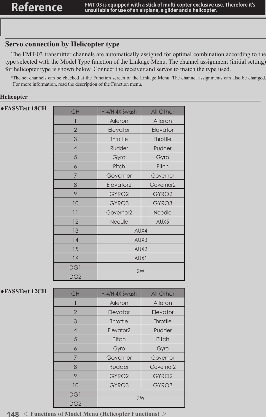
![149<Functions of Model Menu (Helicopter Functions) >Reference FMT-03 is equipped with a stick of multi-copter exclusive use. Therefore it's unsuitable for use of an airplane, a glider and a helicopter.S1●SelectthefunctionnameandreturntotheprecedingscreenbypushingtheRTNbuttonorpushingtheHome/Exitbutton.<Editdial>PIT CURVE/PIT TRIMPIT CurveThis function adjusts the pitch operation curve for each ight condition for the optimal ight state relative to movement of the throttle stick.*Up to 17 points can be set for the point curve types. However, when using the 3 points or 5 points specied to create a curve, a simple curve can be created by reducing the number of input points to 3 or 5, and then entering the specied value at the corresponding points that you created a curve.●Pointcurvetypeis9points(initial),butforsimpleuse,4~5pointsaresufcient.Normal curve adjustment●Fornormalcurve,usuallyuse[POINT]typeandcreateabasicpitchcurvecenteredabouthovering.UsethisfunctiontogetherwiththeTHRcurve(normal)functionandadjustthecurvesothatup/downcontrolisbestataconstantenginespeed.Idle up curve adjustment●Forthehighsidepitchcurve,setthemaximumpitchwhichdoesoverloadtheengine.Forthelowsidepitchcurve,createcurvesmatchedtoloop,roll,3D,andotherpurposesandusetheidleupcurvesaccordingtotheperformance.Throttle hold curve adjustment●Thethrottleholdcurveisusedwhenexecutingautorotationdives.Operation precautionsWARNINGWhen actually starting the engine and ying, always set the idle up condition switch to OFF and start the engine in the idling state.(Currently selected condition name)●Select[PITCURVE] at the modelmenuandcallthesetupscreenshownbelowbypushingtheRTNbutton.●Group/singlemodeswitching(For more information, refer to the description at the back of this manual.)●Mixingcurvesetting*For a description of the curve setting method, see the description at the back of this manual.●Pitchservospeedsetting(For a description of the setting method, see the description at the back of this manual.)●Pitchtrimcopy●Pitchtrimoperatingposition(dottedline)Scrolling●Movingcursor●Selectingmode●Adjustingvalue●PushtheS1 buttontocallnextpage.](https://usermanual.wiki/Futaba/FMT-03-24G.User-Manual-Part-II/User-Guide-3285340-Page-69.png)
![150 <Functions of Model Menu (Helicopter Functions) >Reference FMT-03 is equipped with a stick of multi-copter exclusive use. Therefore it's unsuitable for use of an airplane, a glider and a helicopter.Normal Curve Idle-up 1 Curve Idle-up 2 Curve Hold Curve●Pitch Curve (Example)●Group/Singleitem:Whenyoualsowanttoinputthesamesettingcontentsatotherconditions,performsettinginthegroupmode.Inthiscase,thesamecontentsareinputtotheotherconditionssetinthegroupmode.Whenyouwanttoseteachconditionindependently,selectthesinglemode(initialsetting).Otherconditionscanbesetindependently.Setting method●Pittrimcopy(Hover/high/low) Thepitchtrimoperatingpositioncanbecopiedtothepitchcurve. Movethecursortothe[COPY]itemandpushtheRTNbutton. Aftercopying,returnthepitchtrimtothecentertocallthelastoperatingposition.The screens shown below are curves created by entering the pitch rate at low, center, and high side (3 points or 5 points) at each condition. When actually creating a curve, input the rate specied at the fuselage (or the reference value).*For a description of the curve setting method, see the description at the back of this manual.Curve setting examples(Continued on next page)Pitch Trim (Hovering pitch, high pitch, low pitch)The hovering pitch, low pitch, and high pitch trim setup screen can be called from the PIT curve setup screen.●Hoveringpitchtrimsetting●Low/highpitchtrimsetting](https://usermanual.wiki/Futaba/FMT-03-24G.User-Manual-Part-II/User-Guide-3285340-Page-70.png)
![151<Functions of Model Menu (Helicopter Functions) >Reference FMT-03 is equipped with a stick of multi-copter exclusive use. Therefore it's unsuitable for use of an airplane, a glider and a helicopter.Hovering pitch trimThe Hovering Pitch trim function trims the pitch near the hovering point. Normally, it is used with the hovering condition. The hovering pitch can be ne tuned for changes in rotor speed accompanying changes in temperature, humidity, and other ight conditions. Adjust the hovering pitch so that rotor speed is constant. This function can be used together with the hovering Throttle Trim function for more delicate operation.Setting method●Whenusingonlythehovering(normal)condition,switchthegroupmodetothesinglemode(initialsetting)beforesetting.●SetthefunctiontoACT[ON].●Selecttheadjustmentknob.●Thetrimoperationmode(Mode:CTRM/NORM)canbeselected. CTRMmode:Maximumamountofchangenearcenterbycentertrimoperation(recommended) NORMmode:Normaltrim(parallelmovementtrim)operation.Theadvantageofusingthismodeisthatthehoveringpitchcanbeadjustedwithoutchangingthecurve.●Trimadjustmentrange(Range)setting Whenthisvalueismadesmall,trimcanonlybeusednearthecenter.●Thetrimratecanbeadjustedandtheoperationdirectioncanbechanged.High Pitch/Low Pitch TrimHigh Pitch/Low Pitch Trim is the pitch servo high side and low side trim function.Setting method●Whensettingtheadjustmentknobscommontoalltheconditions,settheminthegroupmode.●SetthefunctiontoACT(ON).●Selecttheadjustmentknobs.●Thetrimratecanbeadjustedandtheoperationdirectioncanbechanged.●Trimactsashighsideorlowsidetrimwiththecenterasthestandard.](https://usermanual.wiki/Futaba/FMT-03-24G.User-Manual-Part-II/User-Guide-3285340-Page-71.png)
![152 <Functions of Model Menu (Helicopter Functions) >Reference FMT-03 is equipped with a stick of multi-copter exclusive use. Therefore it's unsuitable for use of an airplane, a glider and a helicopter.S1●SelectthefunctionnameandreturntotheprecedingscreenbypushingtheRTNbuttonorpushingtheHome/Exitbutton.<Editdial>THR CURVE/THROTTLE HOVER TRIMTHR CurveThis function adjusts the throttle operation curve for each condition for optimum engine speed to throttle stick movement. Up to 17 curve points can be set for the point curve type, however, when the 5 points and other point data is used, a simple curve can be easily created by reducing the number of input points of the curve to 5 and entering the specified value at the corresponding points.Normal curve adjustment●Normalcurvecreatesabasiccurvecenteredaroundhovering.Useitalongwiththenormalpitchcurveandadjustsothatup/downcontrolataconstantenginespeediseasiest.Idle up curve adjustment●Setaidleupcurvethatmaintainsaconstantspeedatalltimes,evenduringoperationwhichreducesthepitchperformedinight.Createacurvematchedtoloop,roll,3D,orotherpurposesandtheidleupcurveaccordingtotheperformance.Operation precautionsWARNINGWhen actually starting the engine and flying, always set the idle up condition switch to OFF and start the engine in the normal/motor at idle mode.Setting method●Group/singleitem:Whenyouwanttosimultaneouslyenterthesamesettingstootherfunctions,makethesettingsinthegroupmode.Inthiscase,thesamesettingcontentsareenteredtotheallconditions.Whenyouwantto seteachconditionindependently,makethesettingsafterselectingthesinglemode(Initialsetting).●Throttlehovertrimcopy Thethrottlehovertrimoperatingpositioncanbecopiedtothethrottlecurve. Movethecursortothe[COPY]itemandpushtheRTNbutton. Aftercopying,returnthepitchtrimtothecentertocallthelastoperatingposition.(Currently selected condition name)●Select[THRCURVE]atthemodelmenuandcallthesetupscreenshownbelowbypushingtheRTNbutton.●Mixingcurvesetting*For a description of the curve setting method, see the description at the back of this manual.●Throttlehovertrimcopy●Throttlehovertrimoperatingposition(dottedline)Scrolling●Movingcursor●Selectingmode●Adjustingvalue●PushtheS1 buttontocallnextpage.](https://usermanual.wiki/Futaba/FMT-03-24G.User-Manual-Part-II/User-Guide-3285340-Page-72.png)
![153<Functions of Model Menu (Helicopter Functions) >Reference FMT-03 is equipped with a stick of multi-copter exclusive use. Therefore it's unsuitable for use of an airplane, a glider and a helicopter.Normal Curve Idle-up 1 Curve Idle-up 2 Curve●Throttle Curve (Example)The curves shown below are created by using the point curve type and inputting the data of the 5 points 0% (low side), 25%, 50% (center), 75%, 100% (high) side at each condition. They are created by reducing the number points of the line to 5. When actually creating a curve, enter the data specied per the aircraft (or the reference value).*For a description of the curve creation method, see the description at the back of this manual.Curve setting examplesThrottle Hover trimThe Throttle Hover trim setup screen can be called from the THR Curve setup screen.The Throttle Hover function trims the throttle near the hovering point. Normally, use it with hovering conditions. Changes in rotor speed accompanying changes in the temperature, humidity, and other flight conditions can be trimmed. Adjust the throttle so that rotor rotation is most stable. More delicate trimming is also possible by using this function along with the Hover Pitch function.Setting method●Whenusingthehovering(normal)conditiononly,switchthegroupmodetothesinglemode(initialsetting)andmakethesettings.●SetthefunctiontoACT([ON]).●Selecttheadjustmentknob.●Thetrimoperationmode(Mode:CTRM/NORM)canbeselected. CTRMmode:Maximumrateofchangenearcenterbycentertrimoperation(recommended) NORMmode:Normaltrim(horizontalmovementtrim)operation.●Trimadjustmentrange(Range)setting Whenthevalueismadesmall,trimactsonlynearthecenter.●Thetrimratecanbeadjustedandtheoperationdirectioncanbeset.●Setsthedialused.](https://usermanual.wiki/Futaba/FMT-03-24G.User-Manual-Part-II/User-Guide-3285340-Page-73.png)
![154 <Functions of Model Menu (Helicopter Functions) >Reference FMT-03 is equipped with a stick of multi-copter exclusive use. Therefore it's unsuitable for use of an airplane, a glider and a helicopter.Setting method●Activatethefunction1.Select"ACT/INH"andpushtheRTNbutton.2.Scrollingtheeditdialandswitchthedisplayto[INH]or[ACT].3.PushtheRTNbutton.●Group/singlemodeselection.1.Select"GROUP"andpushtheRTNbutton.2.Scrollingtheeditdialandswitchthedisplayto[GROUP]or[SINGLE].3.PushtheRTNbutton.●ON/OFFswitchsetting1.Select"SWITCH"andpushtheRTNbutton.2.Ahardwareselectionscreenisdisplayed.SelectthehardwareandpushtheRTNbutton.●Highsideoperationrangesetting1.Select"HIGH"andpushtheRTNbutton.2.Scrollingtheeditdialandadjustthehighsideoperationrange.3.PushtheRTNbutton.●Lowsideoperationrangesetting1.Select"LOW"andpushtheRTNbutton.2.Scrollingtheeditdialandadjustthelowsideoperationrange.3.PushtheRTNbutton.●Theneutralpositionof"CONTROL"setting1.Select"CENTER"andpushtheRTNbutton.2.Scrollingtheeditdialandadjusttheneutralposition.3.PushtheRTNbutton.●Limiteractivationpositionadjustmentcontrolsetting1.Select"CONTROL"andpushtheRTNbutton.2.Ahardwareselectionscreenisdisplayed.SelectthehardwareandpushtheRTNbutton.Throttle Limiter*When the limiter operation range adjustment control is NULL, the throttle limiter function is not activated.This function limits throttle operation to within a certain range. Control which adjusts the operating range during ight can be set. (Effective only when the model type is helicopter.)●OpentheTHRCURVEsetupscreen.PushS1buttontoadvancetonextpageanddisplaypage4.●Throttlelimiteractivationposition●Conditiongroup/single●ThrottlelimiterfunctionACT/INH●MixingON/OFFswitch ●Limiteractivationpositionadjustmentcontrol●Thelimitvalueattheoperationhardwareneutralpositioncanbeadjustedusingthethrottlelimiter.●Highsideoperationrange●Lowsideoperationrange●WhenCENTERisINH.Themotionwiththeequalupperandlowersidesiscarriedout.●WhenCENTERis28%.TheamountofoperationsaboveCONTROLincreases. ThehighsideofathrottlecanrestricttothisrangebyCONTROL.The neutral position of CONTROLThe neutral position of CONTROL](https://usermanual.wiki/Futaba/FMT-03-24G.User-Manual-Part-II/User-Guide-3285340-Page-74.png)
![155<Functions of Model Menu (Helicopter Functions) >Reference FMT-03 is equipped with a stick of multi-copter exclusive use. Therefore it's unsuitable for use of an airplane, a glider and a helicopter.S1●SelectthefunctionnameandreturntotheprecedingscreenbypushingtheRTNbuttonorpushingtheHome/Exitbutton.<Editdial>ACCELERATIONThis function is used to adjust the pitch and the throttle rise characteristic at acceleration/deceleration operation. An acceleration function which temporarily increases the pitch and throttle operations at throttle stick acceleration/deceleration operation can be set.Example of acceleration function use●Whenusedforpitchcontrol,theaccelerationfunctioniseffectivewhenyouwanttoquickentheresponseofthemodelat3Doncollectivepitch. Whenused,highpitchtemporarilyexceedsmaximumpitch,butimmediatelyreturnstomaximumpitch.●Pitchsetting●ThrottlesettingSetting method●Accelerationcanbesetatbothsettingatacceleration(high)andsettingatdeceleration(low). (Theoperationpointisdisplayedonagraph.)●Accelerationratesetting(Rate)●Thereturntimeafteroperation(Dumping)canbeset.●Theoperationpointataccelerationanddecelerationcanbeset.Whenanoperationpointisexceeded,accelerationisperformed.Note:Whenusingtheaccelerationfunction,sincethepitchstrokeislarge,makeyoursettingssothereisnobindingofyourlinkage.(Currently selected condition name)●Select[ACCELERATION]atthemodelmenuandcallthesetupscreenshownbelowbypushingtheRTNbutton.●Actposition●CurrentpositionScrolling●Movingcursor●Selectingmode●Adjustingvalue●PushtheS1 buttontocallnextpage.](https://usermanual.wiki/Futaba/FMT-03-24G.User-Manual-Part-II/User-Guide-3285340-Page-75.png)
![156 <Functions of Model Menu (Helicopter Functions) >Reference FMT-03 is equipped with a stick of multi-copter exclusive use. Therefore it's unsuitable for use of an airplane, a glider and a helicopter.S1●SelectthefunctionnameandreturntotheprecedingscreenbypushingtheRTNbuttonorpushingtheHome/Exitbutton.<Editdial>THR HOLDThis function sets the throttle cut position for auto rotation. The throttle position can also be set to an idling position. Setting of these 2 positions can be selected by a switch. This allows use for switching during training.Example of use●Sincethrottleholdhas2modes(Cut)and(Idle),usingitintheIdlingmodeduringtrainingandintheCutmodewhenstoppingtheengine.Note:WhenthrottleholdissettoONinthenormalcondition,throttleholdactsandthethrottleservoisdeactivated.AlwayssetthrottleholdtoONintheholdcondition.●Settotheenginestopposition.●Settotheidlingposition.Setting method●Operationmodeselection Manualmode(MANUAL):Thethrottleholdfunctionisoperatedbyswitchoperationonly. Automode(AUTO):Thethrottleholdfunctionoperationislinkedtothethrottlestickposition. Autopositionsetting:Whentheautomodeisselected,thethrottleposition(autoposition)canbeselected.MovethethrottlesticktothepositionyouwanttosetandpushtheRTNbutton.(Autopositionisdisplayed.)●Holdpositionadjustment ThrottleHold(Cut)setsthethrottlecutposition.Adjustitsothatthecarburetorisfullclose. ThrottleHold(Idle):Makethisadjustmenttomaintainidling.Adjustmentscanbemadebasedonthethrottlecurveidleposition.●Thethrottleservooperatingspeedcanbeadjusted.(Speed)●Throttlecutortrainingfunctioncanbeswitchedbyholdfunctionselectorswitch.Operation precautionsWARNINGWhen starting the engine, conrm that the idle up condition and throttle hold condition are OFF.(Currently selected condition name)●Select[THRHOLD]atthemodelmenuandcallthesetupscreenshownbelowbypushingtheRTNbutton.●Holdposition●CurrentpositionScrolling●Movingcursor●Selectingmode●Adjustingvalue●PushtheS1 buttontocallnextpage.](https://usermanual.wiki/Futaba/FMT-03-24G.User-Manual-Part-II/User-Guide-3285340-Page-76.png)
![157<Functions of Model Menu (Helicopter Functions) >Reference FMT-03 is equipped with a stick of multi-copter exclusive use. Therefore it's unsuitable for use of an airplane, a glider and a helicopter.S1●SelectthefunctionnameandreturntotheprecedingscreenbypushingtheRTNbuttonorpushingtheHome/Exitbutton.<Editdial>SWASH MIXThe swash mix function is used to correct the swash plate in the aileron (roll) direction and elevator (cyclic pitch) corresponding to each operation of each condition.Adjustment by independent curve for aileron, elevator, and pitch operations is possible. The operation can be smoothly adjusted by calling up the “Curve setup” screen by pushing the EDIT button with moving the cursor to the mixing item that corresponds to the mixing and direction which needs correction.Example of use●Asanexample,useswashmixingtocorrectundesirabletendenciesintherolldirection●ForaconditionwhichusesAILtoELE,setthisfunctiontoON.Whenraisingthenoseatarightroll,whentheRateBsideisinputandtherightaileronisoperated,theelevatormovestothedownside.TunebyadjustingtheRate.Forrightroll,adjusttotherateAside.Setting method●Whenusingthisfunction,movethecursortothe[ACT]itemandpushtheRTNbuttontoswitchtothedatainputmode.TurntheeditdialtotheleftandpushtheRTNbutton.(ONisdisplayed.)●Whenyouwanttosetthesamecontentsatotherconditions,selectthegroupmode.Whenyouwanttosettheselectedconditiononly,selectthesinglemode(initialsetting).●Thecorrectionratecanbesetbycurve.● Aswitchcanbeset. When[--]isset,theswashmixingfunctionisoperatedbymerelyselectingthecondition. Whensettingan[ON]/[OFF]switch,movethecursortothe[--]itemandpushtheRTNbuttontocalltheselectionscreenandsettheswitchanditsONposition.(Currently selected condition name)●Select[SWASHMIX]atthemodelmenuandcallthesetupscreenshownbelowbypushingtheRTNbutton.●Group/singlemodeswitching(For more information, refer to the description at the back of this manual.)●Mixingcurvesetting*For a description of the curve setting method, see the description at the back of this manual.Scrolling●Movingcursor●Selectingmode●PushtheS1 buttontocallnextpage.](https://usermanual.wiki/Futaba/FMT-03-24G.User-Manual-Part-II/User-Guide-3285340-Page-77.png)
![158 <Functions of Model Menu (Helicopter Functions) >Reference FMT-03 is equipped with a stick of multi-copter exclusive use. Therefore it's unsuitable for use of an airplane, a glider and a helicopter.S1●SelectthefunctionnameandreturntotheprecedingscreenbypushingtheRTNbuttonorpushingtheHome/Exitbutton.<Editdial>THROTTLE MIXThis function corrects slowing of engine speed caused by swash plate operation during aileron or elevator operation. The method of applying clockwise or counterclockwise torque when pirouetting can also be corrected.An acceleration function which temporarily increases the throttle side correction rate relative to rapid stick operation can also be set.Setting example●AILtoTHRappliesaloadtotheengineandcorrectsslowingoftheenginespeedwhentheaileronstickwasoperated.EngineracingcanbeadjustedindependentlyattherightaileronandleftaileronbyRatesAandB.Setting method●Whenusingthisfunction,movethecursortothe[ACT]itemandpushtheRTNbuttontoswitchtothedatainputmode.TurntheeditdialtotheleftandpushtheRTNbutton.(ONisdisplayed.)●Whenyouwanttosetthesamecontentsatotherconditions,selectthegroupmode. Whenyouwanttosettheselectedconditiononly,selectthesinglemode(initialsetting).●Thecorrectionratecanbesetbycurve.●Aswitchcanbeset. When[--]isset,theswashmixingfunctionisoperatedbymerelyselectingthecondition. Whensettingan[ON]/[OFF]switch,movethecursortothe[--]itemandpushtheRTNbuttontocalltheselectionscreenandsettheswitchanditsONposition.When correction is necessary, move the cursor to the mixing item corresponding to the mixing that needs correction and push the RTN button to call the curve setup screen, and then correct the slowing.<Acceleration function setting>●Accelerationcanbesetforbothsettings(Left)and(Right)●Accelerationratesetting(Rate)●Thereturntime(Dumping)afteroperationcanbeset.●Theoperationpointwhenthecorrectionrateisincreasedanddecreasedcanbesetindependently.Whenanoperationpointisexceeded,accelerationoperationisperformed.(Currently selected condition name)●Select[THROTTLEMIX]atthemodelmenuandcallthesetupscreenshownbelowbypushingtheRTNbutton.●Group/singlemodeswitching(For more information, refer to the description at the back of this manual.)●Mixingcurvesetting*For a description of the curve setting method, see the description at the back of this manual.●AccelerationsettingsScrolling●Movingcursor●Selectingmode●PushtheS1 buttontocallnextpage.](https://usermanual.wiki/Futaba/FMT-03-24G.User-Manual-Part-II/User-Guide-3285340-Page-78.png)
![159<Functions of Model Menu (Helicopter Functions) >Reference FMT-03 is equipped with a stick of multi-copter exclusive use. Therefore it's unsuitable for use of an airplane, a glider and a helicopter.S1●SelectthefunctionnameandreturntotheprecedingscreenbypushingtheRTNbuttonorpushingtheHome/Exitbutton.<Editdial>PIT to NEEDLE MIXINGThis mixing is used when the engine is equipped with needle control or other fuel-air mixture adjustment. A needle curve can be set.An acceleration function which temporarily increases needle operation at throttle stick Setting method●Whenusingthisfunction,movethecursortothe[ACT]itemandpushtheRTNbuttontoswitchtothedatainputmode.TurntheeditdialtotheleftandpushtheRTNbutton.(ONisdisplayed.)●Whenyouwanttosetthesamecontentsatotherconditions,selectthegroupmode. Whenyouwanttosettheselectedconditiononly,selectthesinglemode(initialsetting).● Aneedlecurvecanbeset.● Aswitchcanbeset. When[--]isset,themixingfunctionisoperatedbymerelyselectingthecondition. Whensettingan[ON]/[OFF]switch,movethecursortothe[--]itemandpushtheRTNbuttontoswitchtothedatainputmode.PushtheRTNbuttontocalltheselectionscreenandsettheswitchanditsONposition.< Acceleration function setting>●Accelerationcanbesetatbothsettingatacceleration(high)andsettingatdeceleration(low).●Theaccelerationrate(rate)andthereturntimeafteroperation(dumping)canbeset.●Anoperationpoint(actpos)ataccelerationanddecelerationcanbeset.Whenanoperationpointwasexceeded,accelerationoperationisperformed.●Normally,use[POINT]type.●Select[PITtoNEEDLE]atthemodelmenuandcallthesetupscreenshownbelowbypushingtheRTNbutton.(Currently selected condition name)acceleration/deceleration operation can be set. The rise characteristic of the needle servo at acceleration and deceleration operation can be adjusted.●Group/singlemodeswitching(For more information, refer to the description at the back of this manual.)●Mixingcurvesetting*For a description of the curve setting method, see the description at the back of this manual.●AccelerationsettingsScrolling●Movingcursor●Selectingmode●Adjustingvalue●PushtheS1 buttontocallnextpage.](https://usermanual.wiki/Futaba/FMT-03-24G.User-Manual-Part-II/User-Guide-3285340-Page-79.png)
![160 <Functions of Model Menu (Helicopter Functions) >Reference FMT-03 is equipped with a stick of multi-copter exclusive use. Therefore it's unsuitable for use of an airplane, a glider and a helicopter.S1●SelectthefunctionnameandreturntotheprecedingscreenbypushingtheRTNbuttonorpushingtheHome/Exitbutton.<Editdial>PIT to RUD MIXING (REVOLUTION MIXING)Use this mix when you want to suppress the reaction torque generated by main rotor pitch and speed changes during pitch operation. Adjust so that the nose does not move in the rudder direction.An acceleration function which temporarily increases the correction rate at throttle stick acceleration/deceleration operation can be set. The mixing rate at acceleration/deceleration can be set.Setting method●Whenusingthisfunction,movethecursortothe[ACT]itemandpushtheRTNbuttontoswitchtothedatainputmode.TurntheeditdialtotheleftandpushtheRTNbutton.(ONisdisplayed.)●Whenyouwanttosetthesamecontentsatotherconditions,selectthegroupmode. Whenyouwanttosettheselectedconditiononly,selectthesinglemode(initialsetting).●Amixingcurveisset.<Normal condition mixing curve> Themixingcurveratestartsfromasmallvalue. Forarotorwithaclockwiseoperationdirection(polarity),whenpitchwasoperatedattheplusside,setsothatmixingisintheclockwisedirection.First,trimathoveringandthenadjusttheneutralposition.1.Adjustmentbetweenslowandhovering Repeatedlyhoverfromtakeoffandlandfromhoveringataconstantratematchedtoyourownrhythm,andadjustthepitchsothenosedoesnotdeectwhenthethrottleisraisedandlowered.2.Throttlehighside(climbinganddivingfromhovering) Repeatclimbinganddivingfromhoveringataconstantratematchedtoyourownrhythmandadjustthepitchsothatthenosedoesnotdeflectwhenthethrottleisraisedandlowered.However, when a GY Series or other heading hold gyro is used, since correction is performed by the gyro, this mix is not used. If this function is used when the gyro operation mode is the AVCS mode, the neutral position will change.<Idle up condition mixing curve> Setthemixingratesothattherudderdirectionathigh-speedightisstraightahead.Adjustforeachconditionused.<Acceleration function setting>●Accelerationoperationcanbeperformedforbothsettingatacceleration(high)andsettingatdeceleration(low).●Accelerationratesetting(rate)●Thereturntimeafteroperation(dumping)canbeset.●Anoperationpoint(actpos)ataccelerationanddecelerationcanbesetindependently.Whenanoperationpointwasexceeded,accelerationoperationisperformed.●Normally,use[POINT]type.●Select[PITto RUD] at themodelmenuandcallthesetupscreenshownbelowbypushingtheRTNbutton.(Currently selected condition name)●AccelerationsettingsScrolling●Movingcursor●Selectingmode●Adjustingvalue●PushtheS1 buttontocallnextpage.](https://usermanual.wiki/Futaba/FMT-03-24G.User-Manual-Part-II/User-Guide-3285340-Page-80.png)
![161<Functions of Model Menu (Helicopter Functions) >Reference FMT-03 is equipped with a stick of multi-copter exclusive use. Therefore it's unsuitable for use of an airplane, a glider and a helicopter.S1●SelectthefunctionnameandreturntotheprecedingscreenbypushingtheRTNbuttonorpushingtheHome/Exitbutton.<Editdial>GYRO PROGRAMMING / GAIN SENSITIVITYThis function used to adjust gyro sensitivity. The sensitivity and operation mode (Normal mode/AVCS mode) can be set for each condition.The gyro sensitivity can be switched with each condition or the switch. (5 sensitivities)*Compatible with 3 axis gyro (CGY750).Setting method● Whenusingthisfunction,movethecursortothe[ACT]itemandpushtheRTNbuttontoswitchtothedatainputmode.TurntheeditdialtotheleftandpushtheRTNbutton.(ONisdisplayed.)● Whenyouwanttosetthesamecontentsatotherconditions,selectthegroupmode. Whenyouwanttosettheselectedconditiononly,selectthesinglemode(initialsetting).● Threeratescanbe switched foreachcondition.(Rate1/Rate2/Rate3)● AnetuningVRcanbeset.●Select[GYRO]atthemodelmenuandcallthesetupscreenshownbelowbypushingtheRTNbutton.(Currently selected condition name)(Rate No. display)●FinetuningVRsettings●Gyrosensitivityadjustment●Modeselection: [AVCS]/[NORM]●Gyrotypeselection: [GY]/[NORM]Note:Whenusingthe[Gyro2]/[Gyro3]function,assign[Gyro2]/[Gyro3]toanychannelonthefunctionscreen. Alwayssetto[--]both(control)and(trim)forthe[Gyro]functionattheFunctionmenuintheLinkagemenu.●WhentheGYROfunctionbuttonisselected,eachGYROdetailedsettingscreenappears.Scrolling●Movingcursor●Selectingmode●Adjustingvalue●PushtheS1 buttontocallnextpage.](https://usermanual.wiki/Futaba/FMT-03-24G.User-Manual-Part-II/User-Guide-3285340-Page-81.png)
![162 <Functions of Model Menu (Helicopter Functions) >Reference FMT-03 is equipped with a stick of multi-copter exclusive use. Therefore it's unsuitable for use of an airplane, a glider and a helicopter.S1●SelectthefunctionnameandreturntotheprecedingscreenbypushingtheRTNbuttonorpushingtheHome/Exitbutton.<Editdial>GOVERNOR PROGRAMMINGWhen using a Futaba governor, this function is used to switch the RPM of the helicopters head. Up to 3 rates can be set for each condition.*The governor is used by connecting the governor speed setting channel to CH7 (initial setting).*When using an independent governor [ON]/[OFF] switch, connect the AUX([ON]/[OFF]) connector of the governor to CH8 (initial setting) and set the switch to CH8 (Governor2) at the Function menu of the Linkage Menu.*When using the Fuel Mixture function, the mixture servo is controlled from the governor. When transmitting the mixture curve data from the transmitter to the governor, the governor AUX (m.trm) connector must be connected to CH8 (initial setting) and governor side setting performed. See the governor instruction manual.Note:Alwaysset(Control)and(Trim)to[--]for[Governor]and[Governor2]oftheFunctionmenuoftheLinkagemenu.●Select[GOVERNOR]at the modelmenuandcallthesetupscreenshownbelowbypushingtheRTNbutton.(Currently selected condition name)●FinetuningVRsettings●RPMadjustment●Unitdisplayselection: [%]/[rpm]Setting method●Activate the mixing Whenusingthisfunction,movethecursortothe[INH]itemandpushtheRTNbuttontoswitchtothedatainputmode. SelecttheACTmodebyscrollingtheeditdial.*The display blinks. PushtheRTNbuttontoactivatethemixingandreturntothecursormode.(ONisdisplayed.) WhentheGovernorischangedfromthedefaultinhibited(INH)statetotheactive(ACT)state,theendpointmenuwillbedisplayedanditispossibletoutilizetheendpointsforthisgivencondition.*When the function is set ON/OFF at the governor setup screen, the governor rpm setting channel end point servo travel and limit point are now initialized.*When changed from INH to ACT (ON), the servo travel is initialized to 100 and the limit point is initialized to 155.*When operation is changed to INH at all conditions, the servo travel is initialized to 100 and the limit point is initialized to 135.●RPM adjustment MovethecursortotherateitemandpushtheRTNbuttontoswitchtothedatainputmode. Adjusttherpmbyscrollingtheeditdial. Initialvalue:50%(1500rpm) Adjustmentrange:OFF,0~110%(OFF,700~3500rpm)*When the RTN button is pushed for one second, the sensitivity is reset to the initial value.) PushtheRTNbuttontoreturntothecursormode.●Unit diplay selection MovethecursortotheUNITitemandpushtheRTNbuttontoswitchtothedatainputmode.Selecttheunitbyscrollingtheeditdial. PushtheRTNbuttontochangetheoperationmodeandreturntothecursormode.Scrolling●Movingcursor●Selectingmode●Adjustingvalue●PushtheS1 buttontocallnextpage.](https://usermanual.wiki/Futaba/FMT-03-24G.User-Manual-Part-II/User-Guide-3285340-Page-82.png)
![163<Functions of Model Menu (Helicopter Functions) >Reference FMT-03 is equipped with a stick of multi-copter exclusive use. Therefore it's unsuitable for use of an airplane, a glider and a helicopter.●Diplay mode selection*When [rpm] mode is selected above setting, the display mode can be selected.* There is no change in the transmitter output even when the "MODE" is changed. Calibration should be performed via the governor.* In order to use the Governor function of the FMT-03, it is necessary to change the settings on the governor for the low side 700 rpm mode. WhentheMODEoftheGovernorscreen'smodelmenuischanged,thechangeisalsoindicatedon-screen.The chart below indicates the mode percentage and the corresponding RPM. ●Fine tuning VR settings Movethecursortothe[--]itemandpushtheRTNbuttontoaccesstheselectionscreen.Selectthecontrol.*For a description of the switch selection method, see the description at the back of this manual. MovethecursortotherateitemandpushtheRTNbuttontoswitchtothedatainputmode. Adjustthetrimratebyscrollingtheeditdial. Initialvalue:0%(0rpm)main rotor R.P.M. 3900rpm 2700rpm 2100rpm0% 100% 110%main rotor R.P.M. setting channel travel50% : neutral 2500rpm 2000rpm 1500rpm 1000rpm 700rpm3500rpm Adjustmentrange:-20~+20%(-800~+800rpm)*When the RTN button is pushed for one second, the sensitivity is reset to the initial value.) PushtheRTNbuttontoreturntothecursormode.](https://usermanual.wiki/Futaba/FMT-03-24G.User-Manual-Part-II/User-Guide-3285340-Page-83.png)
![164 <Functions of Model Menu (Helicopter Functions) >Reference FMT-03 is equipped with a stick of multi-copter exclusive use. Therefore it's unsuitable for use of an airplane, a glider and a helicopter.COND.HOLD ConditionholdfunctionThis function may be used to x the maximum speed of the engine so that you may adjust flight conditions when the engine is running. An alarm indicates that the function is operating. It will prevent the engine from increasing when adjusting the idle-up settings. While this function is active, the throttle servo position is fixed at the point set from when the function is activated. You must deactivate this function when you are through making adjustments. The system will not allow you to activate/deactivate this function in either of the following states:• Whenanyoftheflightconditionswitchesareon.• Whenthethrottlestickishigherthanthe1/3point.To activate/deactivate condition hold:(Home screen)1.Movethecursorto[CNDHOLD].2.Setthethrottlesticklowerthanthe1/3point.3.PushtheRTNbuttontoactivatetheconditionholdfunction.*When this function is active, "IS ON" appears at the right of the [CND HOLD] display at the left bottom of the screen.(LINKAGE menu/MODEL menu)1.Movethecursorto[COND.HOLD].2.Setthethrottlesticklowerthanthe1/3point.3.PushtheRTNbuttontoactivatetheconditionholdfunction.*Operation is displayed at the bottom of the menu.Function ON: "CND HOLD IS ON" is displayed.Function OFF: "CND HOLD IS OFF" is displayed.](https://usermanual.wiki/Futaba/FMT-03-24G.User-Manual-Part-II/User-Guide-3285340-Page-84.png)
![165<Functions of Model Menu (Helicopter Functions) >Reference FMT-03 is equipped with a stick of multi-copter exclusive use. Therefore it's unsuitable for use of an airplane, a glider and a helicopter.S1●SelectthefunctionnameandreturntotheprecedingscreenbypushingtheRTNbuttonorpushingtheHome/Exitbutton.<Editdial>SWASH RINGSwash ring setting procedure*Perform the following settings after using the edit dial to move the cursor to the item you want to set.1.Activatethefunction: Movethecursortothe[ACT/INH]itemandpushtheRTNbuttontoswitchtothedatainputmode. Switchtheblinkingfrom"INH"to"ACT"byturningtheeditdialtotheleftandthenpushtheRTNbutton.2.Ratesetting: Usetheeditdialtomovethecursortothe[RATE]itempushtheRTNbuttontoswitchtothedatainputmode. Usetheeditdialtosettherate. Initialvalue:100%. Adjustmentrange:50%to200%.*Adjust the rate to maximum swash tilt.(When the RTN button is pushed for 1 second, the rate is reset to the initial value.) PushtheRTNbuttontoendadjustmentandreturntothecursormovemode.Limitstheswashplatetraveltowithinaxedrange.(Helicopteronly)This function limits the swash travel to within a fixed range to prevent damaging of the swash linkage by simultaneous operation of the ailerons and elevators. It is effective in 3D aerobatics which use a large travel.● Theoperatingrangedisplayarea: Theverticaldirectionshowstheelevatortravel.Thehorizontaldirectionshowstheailerontravel.●Themarkershows the stickposition.●Select[SWASHRING]atthelinkagemenuandcallthesetupscreenshownbelowbypushingtheRTNbutton.●Whentheswash ring functionisactivated,acircleisdisplayedintheoperatingrangedisplayareaandtherateinputboxisdisplayed.Stickoperationislimitedtowithintheareaofthiscircle.Scrolling●Movingcursor●Selectingmode●Adjustingvalue<Linkage Menu ><Functions of Linkage Menu (Helicopter Functions) >](https://usermanual.wiki/Futaba/FMT-03-24G.User-Manual-Part-II/User-Guide-3285340-Page-85.png)
![166 <Functions of Model Menu (Helicopter Functions) >Reference FMT-03 is equipped with a stick of multi-copter exclusive use. Therefore it's unsuitable for use of an airplane, a glider and a helicopter.S1●SelectthefunctionnameandreturntotheprecedingscreenbypushingtheRTNbuttonorpushingtheHome/Exitbutton.<Editdial>SWASH Swashoperationlinkagecorrectionfunction.(helicopteronly,exceptswashtypeH-1)Neutral PointAt your linkages, if the servo horn deviates from a perpendicular position at neutral, the linkage compensation functions in this menu may not compensate effectively. To correct this use the neutral point function. This will move the neutral point of the servos to the actual perpendicular position. However, this adjustment changes only the axis point of the compensation functions in this menu, and does not affect the neutral position of other functions.Swash AFRSwash AFR function reduces/increases/reverses the rate (travel) of the aileron, elevator and collective pitch functions, by adjusting or reversing the motion of all servos involved in that function, only when using that function. *Before making the following settings, use the edit dial to move the cursor to the item you want to set.Neutral point setting procedureThe neutral point becomes the correction standard point.*Adjusting the servo horn so that the neutral point is near the 50% position makes the mixing amount small.1.Neutralpointsetting Movethecursortothe[POINT]itemandholdthepitchoperationsothattheservohornisatarightangletothelinkagerodandpushtheRTNbuttonfor1secondandreadtheneutralposition.*The neutral point can also be displayed by bar graph. Afterreadingtheneutralpoint,usetheothercorrectionfunctionstomakefurtheradjustments.Mixing RateThis compensation mixing is used to correct the tendency of the swash-plate for each control. The following compensation mixing is possible; PIT to AIL, PIT to ELE, AIL to PIT, ELE to AIL, and ELE to PIT (HR3 mode.) It adjusts the swash-plate to operate correctly for each control using the corresponding compensation mixing.Linkage CompensationThis compensation mixing is used to correct the tendency of the swash-plate for pitch control at low pitch and high pitch.Speed CompensationThis function is used to cancel the reaction that is generated by the difference of the operation amount of each servo when the swash-plate moves.Swash AFR setting procedureThe swash AFR function makes adjustments so that the servos travel the specified amount by [AILERON], [ELEVATOR], and [PITCH] operation.1.UsetheeditdialtomovethecursortothefunctionyouwanttoadjustandpushtheRTNbuttontoswitchtothedatainputmode.2.AdjusttheAFRratebyturningtheeditdialtotheleftorright. Initialvalue:+50% Adjustmentrange:-100%~+100%(When the RTN button is pushed for 1 second, the AFR rate is reset to the initial value.) PushtheRTNbuttontoendadjustmentandreturntothecursormovemode.●Select[SWASH]atthelinkagemenuandcallthesetupscreenshownbelowbypushingtheRTNbutton.Scrolling●Movingcursor●Selectingmode●Adjustingvalue<Functions of Linkage Menu (Helicopter Functions) ><Linkage Menu >●PushtheS1 buttontocallnextpage.](https://usermanual.wiki/Futaba/FMT-03-24G.User-Manual-Part-II/User-Guide-3285340-Page-86.png)
![167<Functions of Model Menu (Helicopter Functions) >Reference FMT-03 is equipped with a stick of multi-copter exclusive use. Therefore it's unsuitable for use of an airplane, a glider and a helicopter.Mixing rate setting procedureThe HR-3 is taken as an example to describe mixing rate setting. Mixing applied in other swash modes is different, but the setting procedure is the same.*Set the throttle stick to the preset neutral point. Adjust the length of the linkage rod so that the swash plate is horizontal at this position.*The sub trim function can be used to make small adjustments.*Adjust so that the pitch curve is a straight line and pitch operation is maximum.*When making the following setting, use the edit dial to move the cursor to the item you want to set and push the RTN button to switch to the data input mode. Push the RTN button to end adjustment and return to the cursor move mode.1.Adjustmentataileronoperation[AILtoPIT] AdjusttheAILtoPITratesothereisnointerferenceintheelevatororpitchdirectionwhentheaileronstickismovedtotheleftandright.*Adjust by turning the edit dial to the left or right.*The left and right sides can be adjusted individually.2.Adjustmentatelevatoroperation[ELEtoAIL]/[ELEtoPIT] AdjusttheELEtoAILandELEtoPITratessothereisnointerferenceintheaileronorpitchdirectionwhentheelevatorstickismovedupanddown.*Adjust by turning the edit dial to the left and right.*The up and down sides can be adjusted individually.3.Adjustmentatpitchoperation[PITtoAIL][PITtoELE] AdjustthePITtoAILandPITtoELEratessothattheswashplatemovestothehorizontalpositionwhenthethrottlestickwasmovedtomaximumslowandfullhigh.*Adjust by turning the edit dial to the left and right.*The slow and high sides can be adjusted individually.Linkage compensation setting procedure*Perform linkage compensation setting after mixing rate setting.*Linkage compensation compensates for interference by aileron operation with the elevator or elevator operation with the aileron at collective pitch control for low pitch and high pitch.*When making the following setting, use the edit dial to move the cursor to the item you want to set and push the RTN button to switch to the data input mode. Push the RTN button to end adjustment and return to the cursor move mode.1.Compensationataileronoperation[AILERON] Setthethrottletothemaximumslowposition.Movetheaileronsticktotheleftandrightandadjusttheaileroncompensationamountsothatinterferenceintheelevatororpitchdirectionatthattimeisminimum.*Adjust the edit dial to the left and right.*The left and right sides can be adjusted individually.*When the interference increases when the compensation amount was increased, make adjustments with the compensation direction [DIR] as "-".2.Compensationatelevatoroperation[ELEVATOR] Adjusttheelevatorcompensationamountsothattheaileronorpitchdirectioninterferencewhentheelevatorstickwasmovedupanddownisminimum.3.Regardingsteps1and2above,performaileronandelevatorcompensationsimilarlyatthefullhighsideofthethrottlestickalso.Speed compensation setting procedure1.Usetheeditdialtomovethecursortothe"SPEEDCOMPENSATION"itemandpushtheRTNbuttontoswitchtothedatainputmode.2.Setthethrottlesticktotheneutralpointposition.Quicklymovetheelevatorstickandadjustthespeedcompensationamount[SPEEDCOMPENSATION]forminimuminterferenceinthepitchdirection.*Adjust by turning the edit dial to the left and right. PushtheRTNbuttontoendadjustmentandreturntothecursormovemode.<Functions of Linkage Menu (Helicopter Functions) >](https://usermanual.wiki/Futaba/FMT-03-24G.User-Manual-Part-II/User-Guide-3285340-Page-87.png)