Futaba FMT-03-24G Radio Control User Manual Part I Rev 01 170210
Futaba Corporation Radio Control Part I Rev 01 170210
Futaba >
Contents
- 1. User Manual-Part I-Rev.01(170210)
- 2. User Manual-Part II
User Manual-Part I-Rev.01(170210)

1M23Z04404
For model

INTRODUCTION............................................... 4
●Support and Service ......................................... 4
●Application, Export, and Modication ........... 4
●Denitions of Symbols ...................................... 7
●Safety Precautions (do not operate without
reading) ............................................................. 7
BEFORE USE ................................................... 11
●Features of FMT-03 ....................................... 11
●Contents and technical specications ........... 12
●Accessories ....................................................... 13
●Transmitter controls ....................................... 14
Transmitter's antenna .................................... 15
Switch (SA-SH) ............................................... 17
Volume (DA-DD) ............................................ 17
Monitor LED .................................................. 17
Edit dial ........................................................... 17
Home/Exit, U.menu/Mon. Button ................. 19
Maintenance example of a transmitter ........ 19
Micro SD Card ............................................... 20
Connector ........................................................ 21
Installation and removal of the battery ........ 22
●Receiver FMR-03 ............................................ 23
●Telemetry sensor ............................................. 24
●S.BUS2 servo ................................................... 24
●Receiver's antenna installation ...................... 25
●Mounting the servo ......................................... 26
●Safety precautions when installing servos ... 26
●S.BUS2 Devicesetting ..................................... 27
BASIC OPERATION ....................................... 28
●Battery Charging ............................................ 28
●How to turn transmitter power ON/OFF .... 29
●Registration of the user's name ..................... 29
●Home screen .................................................... 30
●User menu ........................................................ 31
●Key lock ........................................................... 32
●Link procedure .............................................. 33
●Range testing your R/C system...................... 35
●Channels connection by multicopter type .... 36
FUNCTIONS OF SYSTEM MENU ................ 37
Display ............................................................. 38
System Timer .................................................. 39
User Name ....................................................... 40
Sound ............................................................... 41
H/W Setting ..................................................... 42
Information .................................................... 44
Range Check .................................................. 45
S.BUS Servo ................................................... 46
FUNCTIONS OF LINKAGE MENU ............. 49
Linkage Menu functions table ...................... 49
Servo Monitor ................................................. 50
Model Select .................................................... 51
Model Type (This function isn't used) .......... 53
System Type .................................................... 54
Function .......................................................... 56
Sub-Trim ......................................................... 58
Servo Reverse ................................................. 59
Fail Safe ........................................................... 60
End Point ........................................................ 61
Throttle Cut ................................................... 62
Idle Down ....................................................... 63
Timer ............................................................... 64
T1-T6 Setting .................................................. 66
Multiprop ........................................................ 67
Function Name ............................................... 68
Telemetry......................................................... 69
Telemetry:receiver [battery] ......................... 70
Telemetry:receiver [EXT-batt] ...................... 71
Telemetry:temperature .................................. 72
Telemetry:rpm sensor .................................... 73
Telemetry:altitude .......................................... 74
Telemetry:altitude [variometer] .................... 75
Telemetry:voltage [battery] ........................... 76
Telemetry:voltage [EXT-volt] ........................ 77
TABLE OF CONTENTS

TABLE OF CONTENTS
Telemetry:GPS [distance] .............................. 78
Telemetry:GPS [speed] .................................. 80
Telemetry:GPS [altitude,variometer,position] ..... 81
Telemetry:Servo sensor [current] [temperature]
[angle] ............................................................. 82
Telemetry:Current sensor [current] [voltage]
[capacity] ......................................................... 83
Sensor .............................................................. 84
Sensor:reload .................................................. 85
Sensor:register ................................................ 85
Sensor:change slot .......................................... 86
Tele. Setting ..................................................... 87
Warning ........................................................... 88
Trainer ............................................................. 89
Stick Alarm ..................................................... 92
Data Reset ....................................................... 93
FUNCTIONS OF MODEL MENU ................. 94
●Common Functions ........................................ 94
Condition Select ............................................. 95
AFR ................................................................ 97
Dual Rate ........................................................ 98
Program Mix ................................................... 99
Gyro ............................................................... 103
DATA ................................................................ 104
●Common Operations used in function setup
screen ............................................................. 104
●Updating ........................................................ 112
Reference.......................................................... 113
●Airplane/Glider Functions ........................... 114
Servo connection by airplane/glider type ... 116
AIL Differential ............................................ 120
Flap Setting ................................................... 121
AIL to Camber FLP ..................................... 122
AIL to Brake FLP ......................................... 123
AIL to RUD ................................................... 124
Airbrake to ELE ........................................... 125
RUD to AIL ................................................... 127
Camber Mix .................................................. 128
ELE to Camber ............................................ 130
Camber FLP to ELE .................................... 131
Buttery ........................................................ 132
Trim Mix 1/2 ................................................. 134
Airbrake (Airplane only) ............................. 136
Gyro (for GYA type gyro) ............................ 138
V-tail .............................................................. 140
Ailevator ........................................................ 141
Winglet .......................................................... 142
Motor ............................................................. 143
Acceleration .................................................. 144
RUD to ELE .................................................. 145
Snap Roll (Airplane only) ............................ 146
●Helicopter Functions .................................... 147
Servo connection by helicopter type ........... 148
PIT Curve ..................................................... 149
PIT trim ......................................................... 150
THR Curve ................................................... 152
Throttle hover trim ...................................... 153
Acceleration .................................................. 155
THR Hold ...................................................... 156
Swash Mix ..................................................... 157
Throttle Mix .................................................. 158
PIT to Needle ................................................ 159
PIT to RUD (Revolution mix) ..................... 160
Gyro (for GY type gyro) .............................. 161
Governor ....................................................... 162
Cond. Hold .................................................... 164
Swash Ring (Linkage Menu) ....................... 165
Swash (Linkage Menu) ................................ 166
Reference
FMT-03 is equipped with a stick of multi-copter
exclusive use. Therefore it's unsuitable for use of an
airplane, a glider and a helicopter.

4<Introduction>
INTRODUCTION
Thank you for purchasing a Futaba® FASSTest-2.4GHz* FMT-03 series digital proportional R/
C system. In order for you to make the best use of your system and to y safely, please read this
manual carefully.
*FASSTest: Futaba Advanced Spread Spectrum Technology extend system telemetry
Due to unforeseen changes in production procedures, the information contained in this manual is
subject to change without notice.
FOR SUPPORT :
(PROGRAMMING AND USER QUESTIONS)
FUTABA Corporation of America
101 Electronics Boulevard, Huntsville, Alabama 35824, U.S.A
Fax: 1-256-461-1059
Phone: 1-256-461-9399
OUTSIDE NORTH AMERICA
Please contact your Futaba importer in your region of the world to assist you with any questions,
problems or service needs.
Please recognize that all information in this manual, and all support availability, is based upon
the systems sold in North America only. Products purchased elsewhere may vary. Always contact
your region’s support center for assistance.
Application, Export, and Modication
1. This product may be used for unmanned aerial vehicle use. It is not intended for use in any
application other than the control of models for unmanned aerial vehicle. The product is subject
to regulations of the Ministry of Radio/Telecommunications and is restricted under Japanese law
to such purposes.
2. Exportation precautions:
(a) When this product is exported from the country of manufacture, its use is to be approved by
the laws governing the country of destination which govern devices that emit radio frequencies. If
this product is then re-exported to other countries, it may be subject to restrictions on such export.
Prior approval of the appropriate government authorities may be required. If you have purchased
this product from an exporter outside your country, and not the authorized Futaba distributor in
your country, please contact the seller immediately to determine if such export regulations have
been met.
(b) Use of this product with other than models may be restricted by Export and Trade Control
Regulations, and an application for export approval must be submitted. This equipment must not
be utilized to operate equipment other than radio controlled models.
3. Modication, adjustment, and replacement of parts: Futaba is not responsible for unauthorized
modication, adjustment, and replacement of parts on this product. Any such changes may void
the warranty.

5
<Introduction>
Compliance Information Statement
This device complies with part 15 of the FCC Rules. Operation is subject to the following three
conditions:
(1) This device may not cause harmful interference, and (2) This device must accept any
interference received, including interference that may cause undesired operation.
(3)RF Radiation Exposure Statement
This equipment complies with FCC radiation exposure limits set forth for an uncontrolled
environment.
This transmitter must not be co-located or operating in conjunction with any other antenna or
transmitter.
The responsible party for the compliance of this device is:
FUTABA Corporation of America
101 Electronics Boulevard, Huntsville, Alabama 35824, U.S.A
Fax: 1-256-461-1059
Phone: 1-256-461-9399
The RBRC. SEAL on the nickel-cadmium battery contained in Futaba products
indicates that Futaba Corporation is voluntarily participating in an industry-wide
program to collect and recycle these batteries at the end of their useful lives, when
taken out of service within the United States. The RBRC. program provides a
convenient alternative to placing used nickel-cadmium batteries into the trash or
municipal waste system, which is illegal in some areas.
(for USA)
You may contact your local recycling center for information on where to return the spent battery.
Please call 1-800-8BATTERY for information on NiCd battery recycling in your area. Futaba
Corporation involvement in this program is part of its commitment to protecting our environment
and conserving natural resources.
*RBRC is a trademark of the Rechargeable Battery Recycling Corporation.
NOTE:
This device complies with Industry Canada license-exempt RSS standard(s). Operation is subject
to the following two conditions: (1) this device may not cause interference, and (2) this device
must accept any interference, including interference that may cause undesired operation of the
device.
This equipment complies with IC radiation exposure limits set forth for an uncontrolled
environment. This equipment should be installed and operated with minimum distance 20cm
between the radiator and your body.
French: Cet appareil radio est conforme au CNR-210 d’Industrie Canada. L’utilisation de ce
dispositif est autorisée seulement aux deux conditions suivantes : (1) il ne doit pas produire de
brouillage, et (2) l’utilisateur du dispositif doit être prêt à accepter tout brouillage radioélectrique
reçu, même si ce brouillage est susceptible de compromettre le fonctionnement du dispositif.
Cet équipement est conforme aux limites d’exposition aux rayonnements IC établies pour un
environnement non contrôlé. Cet équipement doit être installé et utilisé avec un minimum de 20
cm de distance entre la source de rayonnement et votre corps.

6<Introduction>
FLYING SAFETY
WARNING
To ensure the safety of yourself and others, please observe the following precautions:
Have regular maintenance performed. Although your FMT-03 protects the model memories with
non-volatile EEPROM memory (which does not require periodic replacement) and not a battery, the
transmitter still should have regular checkups for wear and tear. We recommend sending your system
to the Futaba Service Center annually during your non-ying-season for a complete checkup and
service.
Battery
Charge the batteries! Always recharge the transmitter and receiver batteries before each ying
session. A low battery will soon die potentially, causing loss of control and a crash. When you begin
your ying session, reset your FMT-03’s built-in timer, and during the session pay attention to the
duration of usage.
Stop ying long before your batteries become low on charge. Do not rely on your radio’s low
battery warning systems, intended only as a precaution, to tell you when to recharge. Always
check your transmitter and receiver batteries prior to each ight.
Where to Fly
We recommend that you y at a recognized model airplane ying eld. You can nd model
clubs and elds by asking your nearest hobby dealer, or in the US by contacting the Academy
of Model Aeronautics.
You can also contact the national Academy of Model Aeronautics (AMA), which has more
than 2,500 chartered clubs across the country. Through any one of them, instructor training
programs and insured newcomer training are available. Contact the AMA at the address or toll-
free phone number below.
Academy of Model Aeronautics
5161 East Memorial Drive
Muncie, IN 47302
Tele. (800) 435-9262
Fax (765) 289-4248
or via the Internet at http:\\www.
modelaircraft.org
Always pay particular attention to the ying eld’s rules, as well as the presence and location
of spectators, the wind direction, and any obstacles on the eld. Be very careful ying in areas near
power lines, tall buildings, or communication facilities as there may be radio interference in their
vicinity.
CAUTION:
To assure continued FCC compliance:
Any changes or modications not expressly approved by the grantee of this device could void the
user's authority to operate the equipment.
This radio transmitter (identify the device by certication number) has been approved by Industry
Canada to operate with the antenna types listed below with the maximum permissible gain
indicated. Antenna types not included in this list, having a gain greater than the maximum gain
indicated for that type, are strictly prohibited for use with this device.
No. Name Gain(Peak) Remark
1 MEIWX-2102RSAX-2400 2.25dBi 1/2 λ Pencil type antenna
7
<Introduction>
Precautions
Application, Export, and Modification Precautions.
1. This product is only designed for use with radio control models. Use of the product described in this instruction
manual is limited to radio control models.
2. Export precautions:
a) When this product is exported, it cannot be used where prohibited by the laws governing radio waves of the
destination country.
b) Use of this product with other than models may be restricted by Export and Trade Control Regulations.
3. Modification, adjustment, and parts replacement
Futaba is not responsible for unauthorized modification, adjustment, or replacement of parts on this product.
■No part of this manual may be reproduced in any form without prior permission.
■ The contents of this manual are subject to change without prior notice.
■ Futaba is not responsible for the use of this product by the customer.
■ Company and product names in this manual are trademarks or registered trademarks of the respective company.
Please observe the following precautions to ensure safe use of this product at all times.
Meaning of Special Markings:
The parts of this manual indicated by the following marks require special attention from the standpoint of safety.
DANGER - Procedures which may lead to dangerous conditions and cause death/serious injury if not
carried out properly.
WARNING - Procedures which may lead to a dangerous condition or cause death or serious injury to the
user if not carried out properly, or procedures where the probability of supercial injury or physical damage is
high.
CAUTION - Procedures where the possibility of serious injury to the user is small, but there is a danger of
injury, or physical damage, if not carried out properly.
= Prohibited = Mandatory
WARNING: Always keep electrical components away from small children.
For safe use
Flying Precautions
WARNING
Never grasp the transmitter antenna while
ying.
■ The transmitter output may drop drastically.
Always make sure that all transmitter stick
movements operate all channels properly in the
model prior to flight. Also, make sure that all
switches, etc. function properly as well. If there
are any diculties, do not use the system until all
inputs are functioning properly.
Never y in the range check mode.
■ In the dedicated range test range check mode, the
transmitter output range is reduced and may cause a
crash.
While operating, never touch the transmitter
with, or bring the transmitter near, another
transmitter, a cellphone, or other wireless
devices.
■ Doing so may cause erroneous operation.
Do not point the antenna directly toward the
aircraft during ight.
■ The antenna is directional and the transmitter output
is weakest. (The strength of the radio waves is greatest
from the sides of the antenna.)
Never fly on a rainy day, when the wind is
strong, and at night.
■ Water could lead to failure or improper functionality
and poor control of the aircraft which could lead to a
crash.
Never turn the power switch on and o during
ight or while the engine or motor is running.
■ Operation will become impossible and the aircraft
will crash. Even if the power switch is turned on,
operation will not begin until transmitter and receiver
internal processing is complete.
Do not fly when you are physically impaired
as it could pose a safety hazard to yourself or
others.
Do not touch the engine, motor, or motor
controller during and immediately after use.
■ These items may become hot during use.
8<Introduction>
Battery and Charger Handling Precautions
DANGER
Do not charge and store the battery in direct
sunlight or other hot places.
Do not charge the battery if it is covered with
any object as it may become very hot.
Do not use the battery in a combustible
environment.
■ The gas ignite and cause an explosion or fire.
Always charge the battery before each ying
session.
■ If the battery goes dead during flight, the aircraft will
crash.
Do not y at the following places:
■ Near another radio control flying field.
■ Near or above people.
■ Near homes, schools, hospitals or other places where
people congregate.
■ Near high voltage lines, high structures, or
communication facilities.
For safety, y so that the aircraft is visible at
all times.
■ Flying behind buildings or other large structures
will not only cause you to lose sight of the aircraft, but
also degrade the RF link performance and cause loss of
control.
From the standpoint of safety, always set the
fail safe function.
■ In particular, normally set the throttle channel to idle.
When flying, always return the transmitter
setup screen to the Home screen.
■ Erroneous input during flight is extremely dangerous.
Always check the remaining capacity of the
transmitter and receiver battery before each
ying session prior to ight.
■ Low battery capacity will cause loss of control and a
crash.
Always check operation of each control
functions and perform a range test before each
flying session. Also, when using the trainer
function, check the operation of both the teacher
and student transmitter.
■ Even one transmitter setting or aircraft abnormality
cause a crash.
Before turning on the transmitter:
1. Always move the transmitter throttle stick
position to the minimum (idle) position.
2. Turn on the transmitter first and then the
receiver.
When turning off the transmitter's power
switch. After the engine or motor has stopped
(state in which it will not rotate again):
1. Turn o the receiver power switch.
2. Then turn o the transmitter power switch.
■ If the power switch is turned on/off in the opposite
order, the propeller may rotate unexpectedly and cause
a serious injury.
■ Also always observe the above order when setting
the fail safe function.
■ Maximum low throttle: Direction in which the engine
or motor runs at the slowest speed or stops.
When adjusting the transmitter, stop the
engine except when necessary. In the case of
a motor, disconnect the wiring and to allow it
to continue operation. When doing so, please
exercise extreme caution. Ensure that the aircraft
is secured and that it will not come into contact
with anything or anyone. Ensure that the motor
will not rotate prior to making any adjustments.
■ Unexpected high speed rotation of the motor/engine
may cause a serious injury.
Do not recharge a battery that is damaged,
deteriorated, leaking electrolyte, or wet.
Do not use the charger in applications other
than as intended.
Do not allow the charger or battery to become
wet.
■Do not use the charger when it or your hands are
wet. Do not use the charger in humid places.
Do not short circuit the battery.
Do not solder or repair, deform, modify, or
disassemble the battery and/or battery charger.
Do not drop the battery into a re or bring it
near a re.
9
<Introduction>
Charge the battery with the dedicated charger
supplied with the set.
■ Charging the battery past the specified value may
cause a re, combustion, rupture, or liquid leakage. When
quick charging, do not charge the battery above 1C.
■ Do not charge the battery while riding in a vehicle.
Vibration will prevent normal charging.
When using the LiFe battery, do not connect
the charger to the balance charge connector and
the power connector at the same time.
■ Doing so could cause a re, combustion, generation of
heat, rupture, or liquid leakage.
Insert the power cord plug firmly into the
receptacle up to its base.
Always use the charger with the specified
power supply voltage.
■ Use the special charger by connecting it to a proper
power outlet.
If the battery liquid should get in your eyes,
do not rub your eyes, but immediately wash
them with tap water or other clean water and get
treated by a doctor.
■ The liquid can cause blindness.
Do not touch the charger and battery for any
length of time during charging.
■ Doing so may result burns.
Do not use a charger or battery that has been
damaged.
Do not touch any of the internal components
of the charger.
■ Doing so may cause electric shock or a burn.
If any abnormalities such as smoke or
discoloration are noted with either the charger
or the battery, remove the battery from the
transmitter or charger and disconnect the power
cord plug and do not use the charger.
■ Continued use may cause fire, combustion,
generation of heat, or rupture.
Do not subject the battery to impact.
■ Doing so may cause fire, combustion, generation of
heat, rupture, or liquid leakage.
WARNING
Use and store the battery and battery charger
in a secure location away from children.
■ Doing so may cause electric shock or injury.
If the battery leaks liquid or generates an
abnormal odor, immediately move it to a safe
place for disposal.
■ Not doing so may cause combustion.
If the battery liquid gets on your skin or
clothing, immediately flush the area with tap
water or other clean water.
■ Consult a doctor. The liquid can cause skin damage.
After the specied charging time has elapsed,
end charging and disconnect the charger from
the receptacle.
When recycling or disposing of the battery,
isolate the terminals by covering them with
insulating tape.
■ Short circuit of the terminals may cause combustion,
generation of heat or rupture.
CAUTION
Do not use the battery with devices other than
the corresponding transmitter.
Do not place heavy objects on top of the
battery or charger. Also, do not place the battery
or charger in any location where it fall.
■ Doing so may cause damage or injury.
Do not store or use the battery and charger
where it is dusty or humid.
■ Insert the power cord plug into the receptacle only
after eliminating the dust.
After the transmitter has been used for a long
time, the battery may become hot. Immediately
remove from the transmitter.
■ Not doing so may cause a burn.
Do not charge the battery in extreme
temperatures.
■ Doing so will degrade the battery performance. An
ambient temperature of 10 ℃ to 30 ℃ (50F to 86F) is
ideal for charging.
Unplug the charger when not in use.
Do not bend or pull the cord unreasonably
and do not place heavy objects on the cord.
■ The power cord may be damaged and cause
combustion, generation of heat, or electric shock.
10 <Introduction>
Never disassemble or modify the micro SD
Card.
Do not unreasonably bend, drop, scratch or
place heavy objects on the micro SD Card.
Since the micro SD Card is an electronic
device, be careful of static electricity.
■ Static electricity may cause erroneous operation or
trouble.
Do not use the micro SD Card near radio and
television sets, audio equipment, motors and
other equipment that generate noise.
■ Doing so may cause erroneous operation.
Do not store the micro SD Card in the
following places:
・ Where the humidity is high
・ Where the temperature difference is severe
Micro SD Card (Commercial Product) Handling Precautions
WARNING
CAUTION
*Read the instruction manual supplied with
the micro SD Card for details.
●Recorded data
The data recorded on the micro SD Card cannot be
compensated regardless of the contents or cause of
the trouble or obstruction.
Futaba does not perform data restoration or recovery
work.
If smoke or an abnormal odor emanates from
the card, immediately turn off the transmitter
power.
Do not use the Micro SD Card where it may be
exposed to water, chemicals, oil, or other uids.
■ Doing so may cause a fire or electric shock by short
circuit.
・ Where it is very dusty
・ Where the card will be exposed to shock and vibration
・ Near speakers and other magnetic devices
Do not expose the card to shock and vibration
and do not remove the card from the card slot
while data is being written or read.
■ The data may be damaged or lost.
Keep wireless equipment, batteries, aircraft,
etc. away from children.
Storage and Disposal Precautions
WARNING
Do not store wireless devices in the following
places:
・ Where it is extremely hot (40 ℃ [104F] or higher) or
cold (-10℃ [14F] or lower)
・ Where the equipment will be exposed to direct
sunlight
・ Where the humidity is high
・ Where vibration is prevalent
・ Where it is very dusty
CAUTION
・ Where the device may be exposed to steam and heat
When the device will not be used for a long
time, remove the battery from the transmitter
and aircraft and store them in a dry place where
the temperature is between 0 and 30℃ [32F and
86F].
■ Left standing 'as is' may will cause battery
deterioration, liquid leakage, etc.
Do not directly expose plastic parts to fuel, oil,
exhaust gas, etc.
■ If left in such an environment, the plastic may be
attacked and damaged.
■ Since the metal parts of the case may corrode, always
keep them clean.
Always use genuine Futaba products such
as transmitter, receiver, servo, FET amplifier,
battery, etc.
Other Precautions
CAUTION
■ Futaba is not responsible for damage sustained by
combination with other than Futaba Genuine Parts.
Use the parts specified in the instruction manual and
catalog.
This product SHOULD NOT been used for the
devices that is directly related to human life and/
or harmful devices for human body such as below
applications.
(1) Medical Devices
(2) Aerospace/Aviation Related Devices
(3) Nucleated Devices e.t.c.

11
<Before Use>
BEFORE USE
Features
FASSTest system
The FMT-03 transmitter has adopted the newly developed bidirectional communication system
"FASSTest". Data from the receiver can be checked in your transmitter. FASSTest is a maximum
18channels (linear 16 channels + switch 2 channels) 2.4GHz dedicated system.
Waterproof:IP-64
The FMT-03 transmitter and FMR-03 receiver are waterproong (IP-64).
S.BUS2 system
By using the S.BUS2 system multiple servos, gyros and telemetry sensors are easily installed with
a minimum amount of cables.
LiFe battery
FMT-03 is operated by a 6.6V/2,100mAh Lithium Ferrite battery.
Micro SD card (Secure Digital memory card) (Not included)
Model data can be saved to a micro SD card (SD:32MB-2GB SDHC:4GB-32GB). When FMT-03
transmitter software les are released, the software can be updated by using a micro SD card update.
Data input
Large graphic LCD and Edit dial substantially improve ease of setup.
Edit button
Edit dial and three edit buttons are provided, and the operating screen can be immediately “Returned”
to the HOME screen during operation. Setting operation can be performed easily by combining this
button with a Edit dial.
Vibration function
Selects a function that alerts the operator to various alarms by vibrating the transmitter in addition
to sounding a buzzer.

12 <Before Use>
Contents and Technical Specications
(Specications and ratings are subject to change without notice.)
Your FMT-03 includes the following components:
• FMT-03 Transmitter
• FMR-03 Receiver
• FT2F2100BV2 LiFe battery & charger
*The set contents depend on the type of set.
Transmitter FMT-03
(2-stick, 18-channel, FASSTest-2.4GHz system)
Transmitting frequency: 2.4GHz band
System: FASSTest 18CH, FASSTest 12CH switchable
Power supply: 6.6V FT2F2100BV2 LiFe battery
Receiver FMR-03
(FASSTest-2.4G system, dual antenna diversity, S.BUS2 system)
Power requirement: 3.7V~7.4V battery or regulated output from ESC, etc. (*1)
Size: 0.92 x 1.36 x 0.42 in. (23.4 x 34.6 x 10.6 mm)
Weight: 0.11 oz. (3g)
(*1) When using an ESC make sure that it is capable of your applications current draw.
Note: The battery in the FMT-03 transmitter is not connected to the battery
connector at initial. Please connect the battery connector before use.
13
<Before Use>
• FT2F2100BV2 transmitter battery pack - the (2,100mAh) transmitter LiFe battery pack may be easily
exchanged with a fresh one to provide enough capacity for extended ying sessions.
• Trainer cord - the optional training cord may be used to help a beginning pilot learn to fly easily by
placing the instructor on a separate transmitter. Note: FMT-03 is connected by an exclusive trainer code
by FMT-03 fellow. It isn't possible to connect with a transmitter of the different model.
• Servos - FMR-03 can use only futaba S.BUS2 servos.
• Telemetry sensor - please purchase an optional sensor, in order to utilize bidirectional communication
system and to acquire the information from a model high up in the sky.
[Temperature sensor : SBS-01T/TE] [Altitude sensor : SBS-01A] [RPM sensor magnet type : SBS-
01RM][RPM sensor optical type : SBS-01RO] [RPM sensor brushless motor type : SBS-01RO] [GPS
sensor : SBS-01G] [Voltage sensor : SBS-01V] [S.BUS servo sensor : SBS-01S] [Current sensor : SBS-
01C]
• Y-harnesses, servo extensions, hub,etc - Genuine Futaba extensions and Y-harnesses, including a heavy-
duty version with heavier wire, are available to aid in your larger model and other installations.
• Receivers - various models of Futaba receivers may be purchased for use in other models. (Receivers for
FASSTest types are available.)
The following additional accessories are available from your dealer. Refer to a Futaba catalog for
more information:
14 <Before Use>
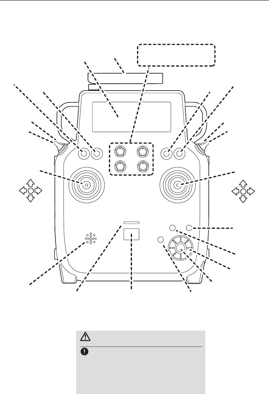
●Antenna
●Monitor LED
●Speaker
●Stick ●Stick
●U.menu/Mon
Button
●Home/Exit
Button
●S1 Button
●RTN Button
●Edit dial
●LCD
●Power Switch
●Switch SB
●Switch SA
●Switch SC
●Switch SD
●Switch SF
●Switch SE ●Switch SG
●Switch SH
●Volume(DA)
●Volume(DC)
●Volume(DB)
●Volume(DD)
J2
J1
J3
J4
Transmitter controls
CAUTION
This transmitter is a self neutral stick.
A throttle stick of a transmitter for R/
C hobbies of normality is a ratchet-type.
Notice should be taken of this difference.
When you release your hold, it becomes
middle-speed, so be careful.
15
<Before Use>
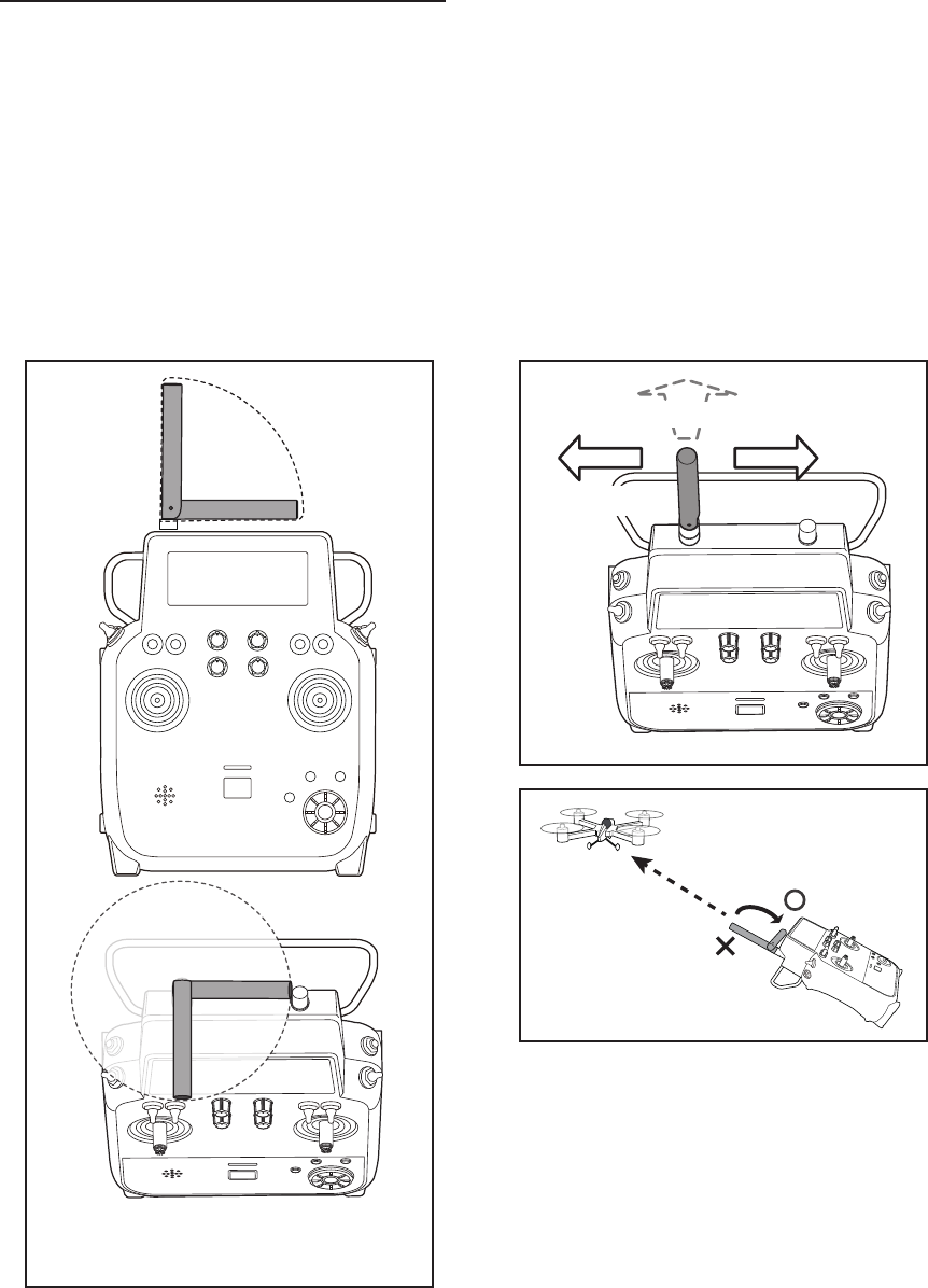
Transmitter's Antenna:
As with all radio frequency transmissions, the
strongest area of signal transmission is from the
sides of the transmitter's antenna. As such, the
antenna should not be pointed directly at the model.
If your flying style creates this situation, easily
move the antenna to correct this situation.
• Rotating antenna
The antenna can be rotated 360 degrees and angled
90 degrees. Forcing the antenna further than this
can damage it. When making an antenna rotate, be
careful so that xing screw doesn't loosen.
Low power
High power High power
Place the antenna at an
angle 90 degrees to the
aircraft.
It is not good to
point the antenna
at a ying model.
90°
360°
Be careful so that antenna xing
screw doesn't loosen.
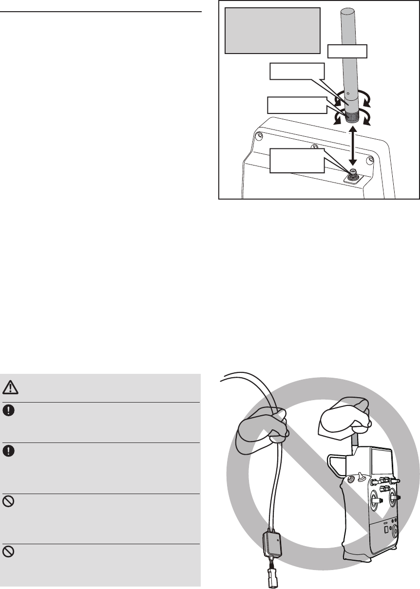
16 <Before Use>
CAUTION
Be sure to install an antenna and do a
ight.
■When there are no antennas, you can't control.
Please do not grasp the transmitter's
antenna during ight.
■Doing so may degrade the quality of the RF
transmission to the model.
Do not carry the transmitter by the
antenna.
■There is the danger that the antenna wire will break
and operation will become impossible.
Do not pull the antenna forcefully.
■There is the danger that the antenna wire will break
and operation will become impossible.
Attachment and removal of an antenna
FMT-03 can attach or remove an antenna.
Dust and water aren't supposed to be stuck in an
antenna connector.
Antenna screw
Rotation part
Install of an antenna
straight to a screw.
Tighten a screw tightly
so as not to loosen. Antenna
This nut isn't
removed.
17
<Before Use>
Switch (SA-SH)
You can choose switch and set the ON/OFF-
direction in the setting screen of the mixing
functions.
Volume
Volume DA - DD:
The volume DA-DD knobs allow analog input.
*The FMT-03 transmitter beeps when the volume knob
reaches the center position.
*You can use each setting screen of the mixing functions to
select volumes and dene the direction of a movement.
DA
DC
DB
DD
SA SC
SF SH
SE SG
SB SD
Monitor LED
• RF-ON → Light Blue light
• RF-OFF → Violet light
• Starting → Red light
• Trainer Student → Blue light
• Range check mode → Slow blinking
• FASSTest receiver link mode → Fast
blinking
Monitor LED display
The status of the transmitter is displayed by LED at
the upper part of the front of a FMT-03.
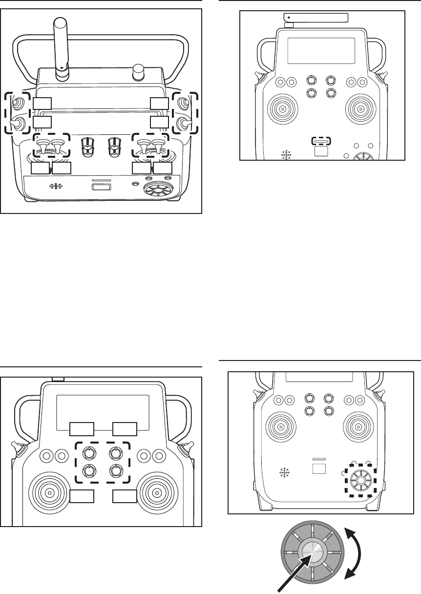
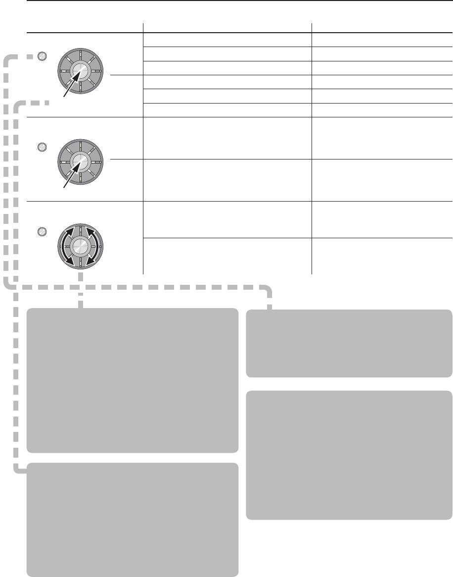
Edit dial
Scroll
Push RTN
18 <Before Use>
S1
RTN
S1
RTN
S1
Edit dial operation Action Reaction
• Short 'push'
S1
If the screen has more than one page.
The cursor moves to the top of next page.
If the screen have only one (1) page. The cursor moves to the top of page.
If the input data mode with blinking the setting data. The input data is canceled.
RTN
At the moving cursor mode. Change to the input data mode.
At the input data mode. Change to the moving cursor mode.
At the input data mode with blinking the setting data. The data is entered.
• Push and hold for
one (1) second. S1 At the HOME screen Key lock On or Off
RTN In the input data mode without blinking the setting
data. Reset to the initialized value.
• Scrolling
Outline
of
Edit
dial
Turn the outline of the edit dial. The cursor moves accordingly.
During the data input mode. Increases or decreases values accordingly.
Edit dial operation
Data input operation is performed using the edit dial.
Movement of cursor, value input or mode selection
:
Movement of the cursor on the menu screen and
movement of the cursor among items on a setup
screen can be controlled by scrolling your finger
to the left and right in the direction of the arrow in
the scrolling diagram above. You can also go to the
next page, if there is a next page.
This scrolling technique is also used for data
input, value input, mode selection, and similar
operations. Examples include: Value, ON, OFF,
INH, ACT, etc.
RTN button:
Push the RTN button when you want to open a
setup screen or to switch between cursor move
mode (reverse display) and data input mode (box
display).
This button can also be used as the enter button
when a conrmation message is displayed on the
screen, etc.
S1 button:
When there is a next page on a menu screen or
setup screen, you can go to that page by pushing
the S1 button. In this case, the cursor moves to
the screen title item of the page.
Exiting setup screen:
To end the operation on a setup screen and
return to the menu screen, move the cursor to the
screen title item and push the RTN button.
To return to home screen directly, push the
Home/Exit button for 1 second.
Alternatively, move the cursor to the screen title
item and push the RTN button to return to the
home screen from a menu screen.
19
<Before Use>
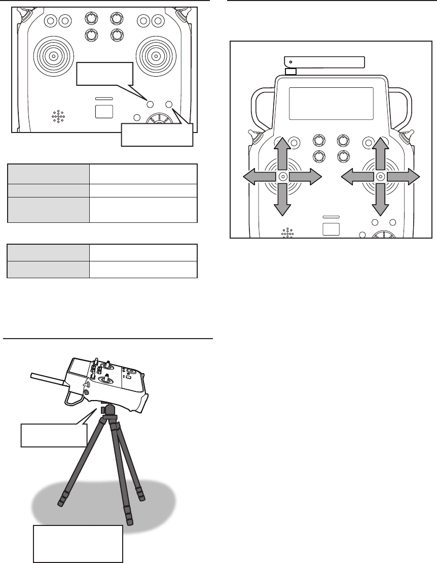
Home/Exit and U.menu/Mon. Button
Home/Exit
Button
U.menu/Mon
Button
Push To Servo Monitor display
Push and hold To User menu
Home/Exit:
U.menu/Mon:
Push Return to the previous
screen
Push and hold Return to the Home screen
It pushes from
HOME screen. To TELEMETRY display
Maintenance example of a transmitter
Tripod Screw
Hole
Camera Tripods or
Monopods.
(not included)
Hole of the VESA (VIDEO ELECTORONICS
STANDARDS ASSOCIATION) standard is
equipped in FMT-03. It's also possible to install it
in the display arm (not included).
2 sticks of FMT-03 can do linear operation in left,
right, up or down.
Operation of sticks
20 <Before Use>
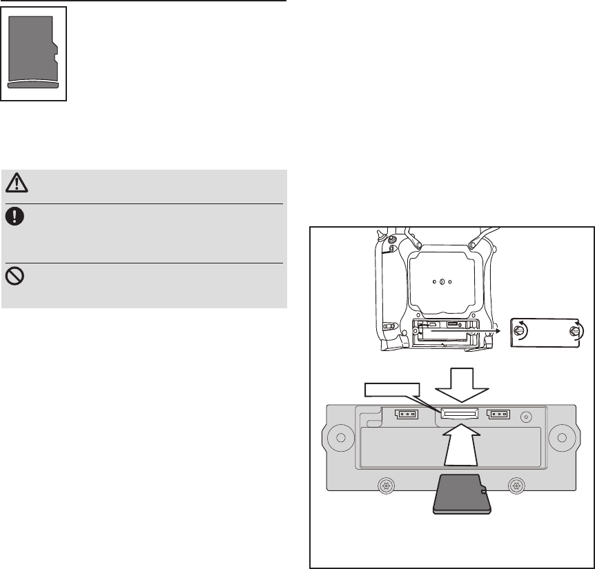
Micro SD card (secure digital memory card) (not
included)
The FMT-03 transmitter model data
can be stored by using any commonly
found micro SD card. When FMT-
03 transmitter update software is
released, the software is updated using
an micro SD card. The FMT-03 is
capable of using micro SD cards with
a memory size between SD:32MB
-2GB SDHC:4GB-32GB.
CAUTION
Be sure to turn off the power to the
transmitter before inserting or removing
the micro SD card.
As the micro SD card is a precision device,
do not use excessive force when inserting.
Micro SD card reader/writer
Saving model data and update files (released
from Futaba) into the micro SD card, you can use
those les on your FMT-03 transmitter. Equipment
for reading and writing micro SD cards is available
at most electronics stores.
Stored data
When you have a problem of saving or reading
data after a long period of use, please get a new
micro SD card.
*We do not have the responsibility of compensating any
failure or damage to the data stored in the memory card no
matter what the reason is. Be sure to keep a backup of your
important data in your micro SD card.
Inserting/removing the micro SD card
② It inserts until it locks micro SD card into SD card slot.
*It is releasable if a card is pushed once again.
*Don't mistake the
direction that the
micro SD card is
inserted.
① Open the battery cover. (Minus driver is used.)
SD card slot
21
<Before Use>
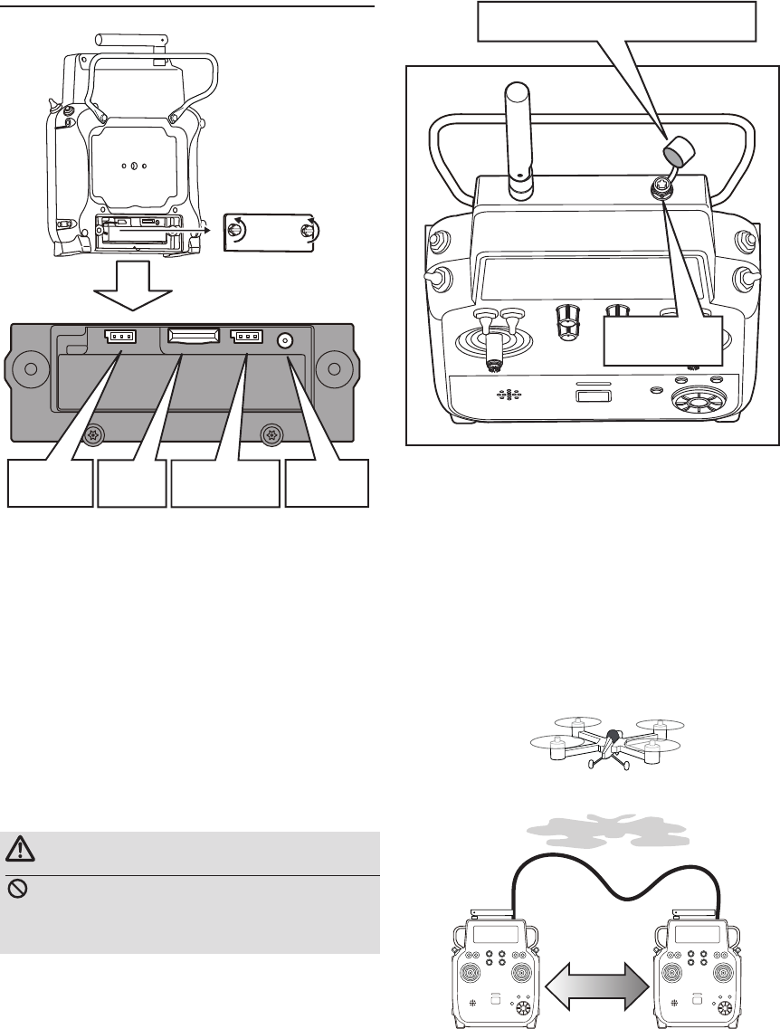
Connector
S.BUS connector (S.I/F)
When setting an S.BUS2 servo and telemetry
sensor, connect them both here.
*Do not connect the battery.
Connector for trainer function
When you use the trainer function, connect the
optional trainer cable between the transmitters for
teacher and student.
*You can set the trainer function on the Trainer Function
screen in the System menu.
*A transmitter of anything but FMT-03 doesn't correspond to
this trainer system.
*An exclusive option trainer code is needed to use a trainer
system.
WARNING
Do not connect any other chargers except
the special charger to this charging
connector.
SD card
Slot
S.BUS (S.I/F)
Connector
Battery
Connector
Connector for battery charger
This is the connector for charging the LiFe
battery FT2F2100BV2 that is installed in the
transmitter. Do not use any other chargers except
the attached special charger corresponding to LiFe
battery.
Charge
Connector
Trainer
Connector
Teacher Student
Change
Remove the cover and connect trainer
cable. Usually put on the cover.
22 <Before Use>
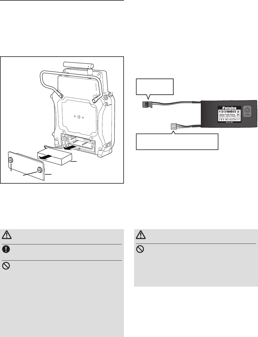
Installation and removal of the FT2F2100BV2
transmitter battery
Battery removal
Note: If you remove the battery while the power
is on, the data you have set will not
be saved.
1. Loosen 2 screws.
2. Open the battery cover.
Attachment of the battery
1. Remove 2 screws.
2. Open the battery cover.
3. Insert a battery.
4. Connect the battery connector.
5. Close the battery cover completely.
6. Tighten 2 screws.
3. Disconnect the battery connector.
4. Remove the battery.
5. Close the battery cover completely.
6. Tighten 2 screws.
WARNING
Be careful not to drop the battery.
Never disconnect the battery connector
from the FMT-03 transmitter after turning
off the power until the screen is completely
blank and the transmitter has shut down
completely.
* Internal devices such as memories may be damaged.
* If there is any problem, the message "Backup Error" will
be shown the next time when you turn on the power of
the transmitter. Do not use the transmitter as it is. Contact
supplier.
WARNING
When closing the battery cover, be careful
that the battery cover does not pinch the
battery lead wires.
*Shorting of the battery lead wires may lead to re and
abnormal heating and cause burns or re disaster.
Battery
Battery cover
Screws
FT2F2100B V2
Lithium Ferrite
Battery
To Transmitter
Connector
Balance charging connector
: It isn't connected to a transmitter.
*The balance charge connector is not
connected in the state where the battery
is set to a transmitter.
23
<Before Use>
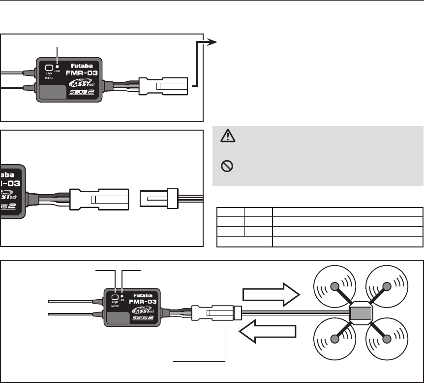
● S.BUS2 Connector
●Be careful about the direction of connector.
●LED Indication
WARNING
S.BUS2 connector
Don't connect an S.BUS servo/gyro to
S.BUS2 connector.
LED Monitor
Green Red Status
Off Solid No signal reception
Solid Off Receiving signals
Alternate blink Unrecoverable error (EEPROM, etc.)
Direction of connector
Receiver FMR-03
(Typical installation)
Antenna
Link/Mode
Switch
Power supply
S.BUS Signal
LED
FMR-03
Attachment
Connector
LF3WBP-12S
3.7V 〜 7.4V
(It is not used for a link.)
S.BUS2 equipment
24 <Before Use>
Telemetry sensor (sold separately)
Your aircraft's data can be checked in the transmitter by connecting various telemetry sensors to the hub
connector of the receiver.
Futaba Telemetry Sensor
Futaba Telemetry Sensor
Futaba Telemetry Sensor
Terminal
box
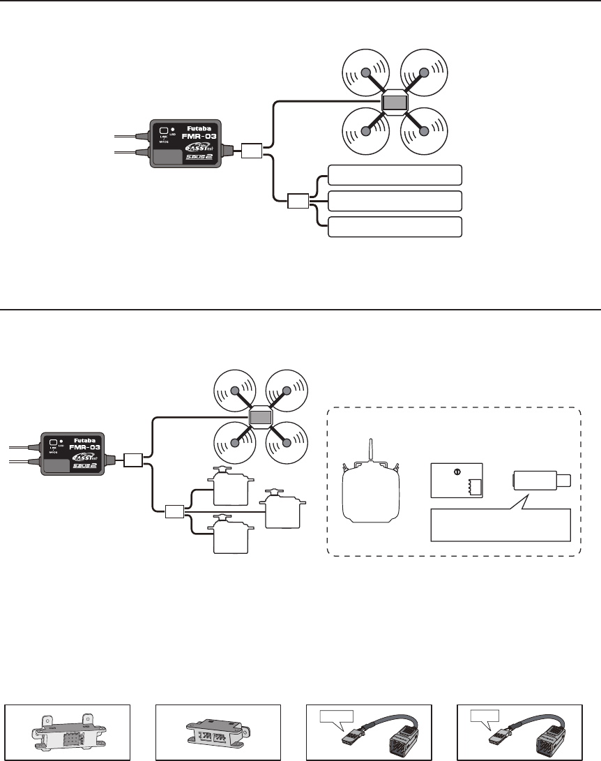
S.BUS2 Servo
Use of multi-copter control box corresponding to S.BUS2 is presupposing for FMR-03. S.BUS2 servo is
connected as shown in the gure.
Hub
S.BUS2
Servo
S.BUS2
Servo
S.BUS2
Servo
Transmitter
with S.BUS
setting
S.BUS servo channel setting device
SBC-1 CIU-2/3
or or
Drivers and Link programs
"S-Link" must be installed.
●Since the channel number is memorized by the
S.BUS servo itself, any connector can be used.
Terminal
box
●4-Terminal box
Four connectors can be inserted
●6-Terminal box (TB16PP)
Six connectors can be inserted
●Hub
Three connectors can be inserted.
●Hub(Another power supply)
Used when using a separate power
supply battery.
Orange Green
25
<Before Use>
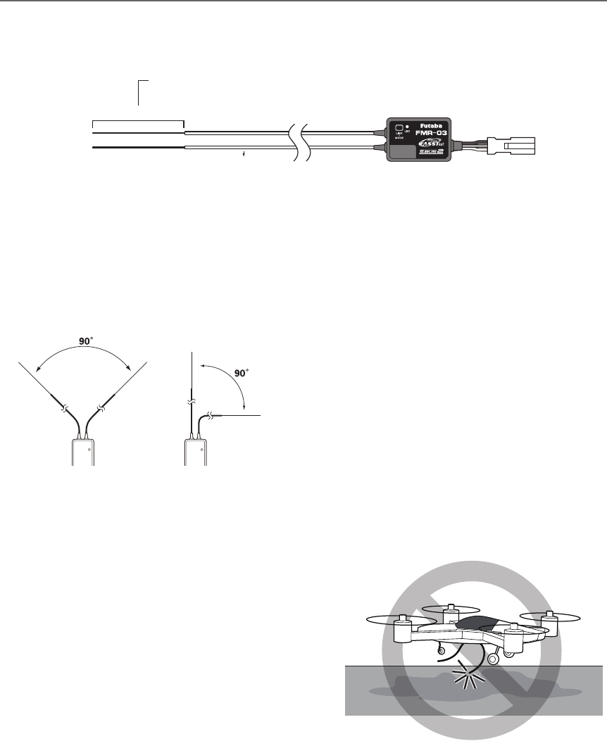
Receiver's Antenna Installation
The FMR-03 has two antennas. In order to maximize signal reception and promote safe modeling Futaba
has adopted a diversity antenna system. This allows the receiver to obtain RF signals on both antennas and
y problem-free.
To obtain the best results of the diversity
function, please refer to the following
instructions:
1. The two antennas must be kept as straight
as possible. Otherwise it will reduce the
effective range.
2. The two antennas should be placed at 90
degrees to each other.
This is not a critical figure, but the most
important thing is to keep the antennas
away from each other as much as possible.
Larger models can have large metal
objects that can effect the RF signal. In this
case the antennas should be placed at
both sides of the model. Then the best RF
signal condition is obtained at any flying
attitude.
3. The antennas must be kept away from
conductive materials, such as metal,
carbon and fuel tank by at least a half
inch. The coaxial part of the antennas does
not need to follow these guidelines, but do
not bend it in a tight radius.
4. Keep the antennas away from the motor,
ESC, and other noise sources as much as
possible.
*The two antennas should be placed at 90 degrees to each other.
*The illustration demonstrates how the antenna should be placed.
*Install in a way that makes sure that the 2 antennas won't touch the ground. When an antenna touches the ground, there
is danger which becomes control impossibility.
Antenna
*Must be kept as straight as possible.
Coaxial cable
FMR-03 Receiver
Antenna don’t touch the ground.
26 <Before Use>
Rubber
grommet
Brass eyelet
Wood screw
Servo mount
2.3-2.6mm nut
washer
Rubber
grommet
Brass eyelet
Servo mount
2.3-2.6mm screw
(Helicopter) (Airplane/Glider)
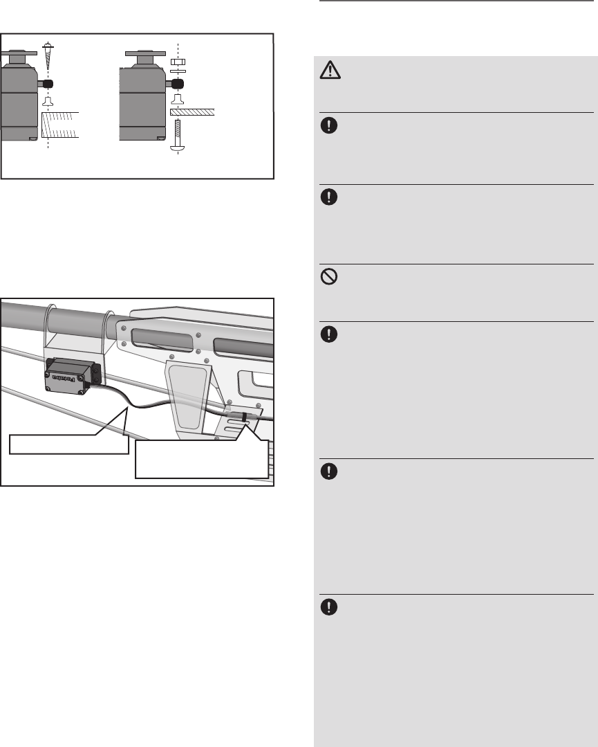
Servo lead wires
To prevent the servo lead cable from being
broken by vibration during flight, provide a
little slack in the cable and fasten it at suitable
points. Periodically check the cable during daily
maintenance.
Fasten about 5-10cm
from the servo outlet so
that the lead wire is neat.
Margin in the lead wire.
Mounting the power switch
When mounting a power switch to an
airframe, make a rectangular hole that is a little
larger than the total stroke of the switch so
that you can turn the switch ON/OFF without
binding.
Avoid mounting the switch where it can be
covered by engine oil and dust. In general, it is
recommended to mount the power switch on the
side of the fuselage that is opposite the mufer.
Safety precautions when you install
receiver and servos
WARNING
Connecting connectors
Be sure to insert the connector until it
stops at the deepest point.
How to protect the receiver from vibration
Wrap the receiver with something soft
such as foam rubber to avoid vibration.
Receiver's antenna
Never cut the receiver's antenna. Do not
bind the receiver's antenna with the cables
for servos.
Locate the receiver's antenna as far as
possible from metals or carbon fiber
components such as frames, cables, etc.
*Cutting or binding the receiver's antenna will reduce the
radio reception sensitivity and range, and may cause a
crash.
Servo throw
Adjust your system so that pushrods will
not bind or sag when operating the servos
to the full extent.
*If excessive force is continuously applied to a servo, the
servo could be damaged due to force on the gear train
and/or power consumption causing rapid battery drain.
Mounting servos
Use a vibration-proof rubber (such as
rubber grommet) under a servo when
mounting the servo on a servo mount. And
be sure that the servo cases do not push
directly to the metal parts such as servo
mount.
*If the servo case contacts the airframe directly, vibration
will travel to and possibly damage the servo.
Mounting the Servo
27
<Before Use>
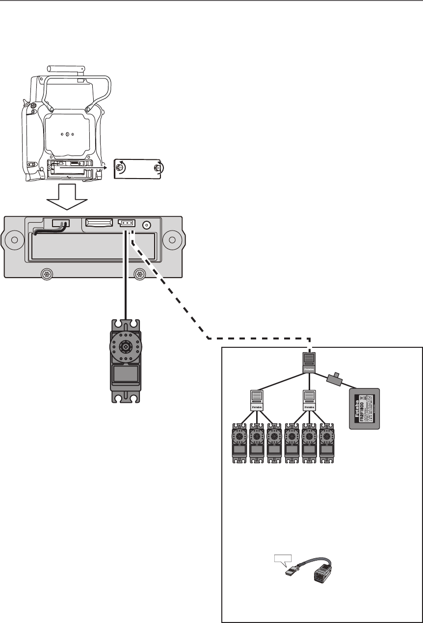
S.BUS2 device setting
S.BUS2 servos or a telemetry sensor can be connected directly to the FMT-03. Channel setting and other
data can be entered for the S.BUS2 servos or sensors.
(S.BUS2 servo)
S.BUS2 device
(Telemetry sensor)
FMT-03
1. Connect the S.BUS device you want to set
with as shown in the gure.
2. Turn on the transmitter power.
3. Call the setup screen.
Servo: System Menu → S.BUS servo
Sensor: Linkage Menu → Sensor
4. Perform setting in accordance with each
screen.
5. This sets the channel and other data for each
S.BUS servo, or telemetry device to be used
with the S.BUS device or receiver.
*It is not necessary to carry out multiple connection
of the battery like a T18MZ/T14SG.
(It will damage, if it connects.)
*When you connect to a transmitter many servos
which consume many current, please use
"Another power supply HUB".
And electric power is supplied to a servo with
another power supply.
Battery
Hub Hub
Hub
(Another power supply)
Hub
(Another power supply)
S.BUS2 Servo
●When separate power supply used
When a large number of servos are used or
when high current servos are used, the servos
can be driven by a separate power supply by
using a separate Power Supply 3-way hub.
Used when using a separate
power supply battery.
Switch
Green
28 <Basic Operation>
BASIC OPERATION
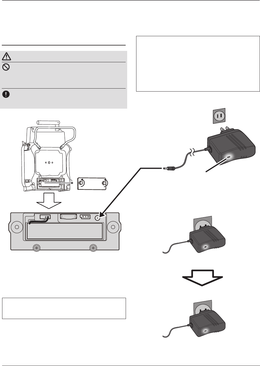
How to charge the LiFe battery FT2F2100BV2
for the transmitter
DANGER
The LiFe battery FT2F2100BV2 is only for
your FMT-03. Do not use this battery for
other equipment.
Be sure to use the attached special charger to
charge the battery.
[Method of charging battery]
Battery Charging
Before charging battery, read the "Cautions for handling battery and battery charger" in the section
"Battery Safety and Handling Instructions".
●Special charger
●AC outlet
To FMT-03 charge
connector
Transmitter Batt.
Charging display
Red solid
Charging
Charge completion
Green solid
Red blink
or
1.Plug the transmitter cord of the special
charger into the charging connector in the
transmitter.
2. Plug the charger into an AC outlet.
3. Check that the charging LED lights.
When the battery will not be used for a long time, to
prevent it from deteriorating we recommend that it be
kept in about the half capacity state instead of fully
charged. Also be careful that the battery does not en-
ter the over-discharged state due to self-discharge.
When the transmitter will not be used for a long time,
you should always remove its battery.
Periodically (about every 3 months) charge the battery.
The charging time when charging the FT2F2100BV2
battery with the optional special charger is approxi-
mately 3 hours.
4. Disconnect the charge plug.
5. Disconnect the AC plug.
29
<Basic Operation>
How to turn transmitter power ON/OFF
When turning on the power, the FMT-03
transmitter will begin emmiting RF automatically
after it conrms the surrounding RF conditions.
When turning on the power of the transmitter
1. Turn on the power switch of the transmitter.
How to stop the transmitter
1. Turn off the power switch of the transmitter.
*The transmitter shuts down at once.
Low battery alarm
When the battery voltage reaches 6.2V, an audible
alarm will sound. Land your aircraft immediately.
It can change from 6.0V to 7.6V by [SOUND] of
[SYSTEM MENU].
It recommends using it with an initial value.
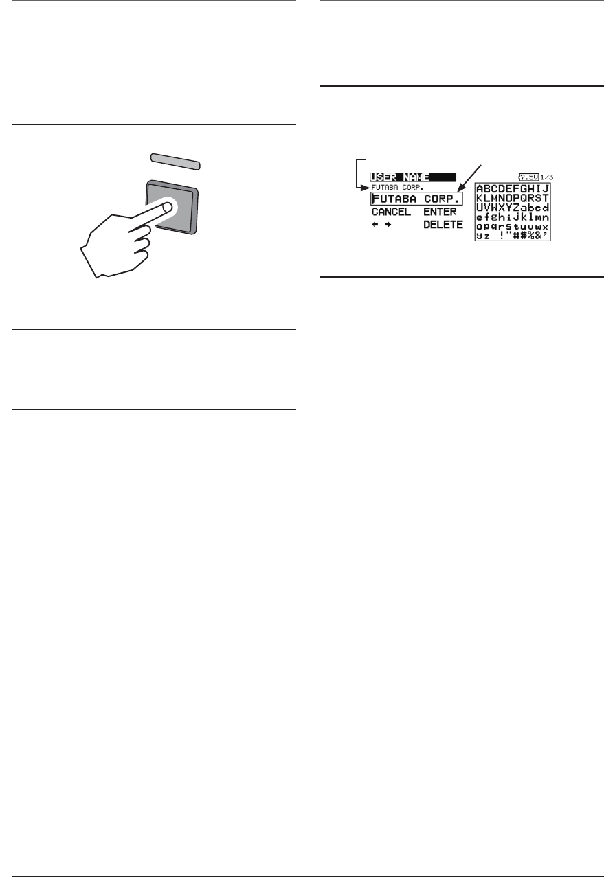
Registration of the user's name
If so desired, the FMT-03 transmitter can
indicate the owner's name.
User's name setup screen
1. Turn on the power of the transmitter.
2. Select [USER NAME] in the system menu and
Push the RTN button.
*The user name set up screen appears.
Current user name Input Box
Changing the user name
1. Change the user name as described below:
[Moving cursor in input box]
Select[←]or[→],andpushtheRTNbutton.
[Deleting a character]
When [DELETE] is selected and the RTN
buttonispushed,thecharacterimmediately
after the cursor is deleted.
[Adding a character]
When a candidate character is selected
from the character list and the RTN button
ispushed,thatcharacterisaddedatthe
position immediately after the cursor.
*A name of up to 12 characters long can be entered as the
user name. (A space is also counted as 1 character.)
2.Attheendofinput,select[ENTER]andpush
the RTN button. (To terminate input and
returntotheoriginalstate,select[CANCEL]
and push the RTN button.)
Push and hold
ON OFF
30 <Basic Operation>
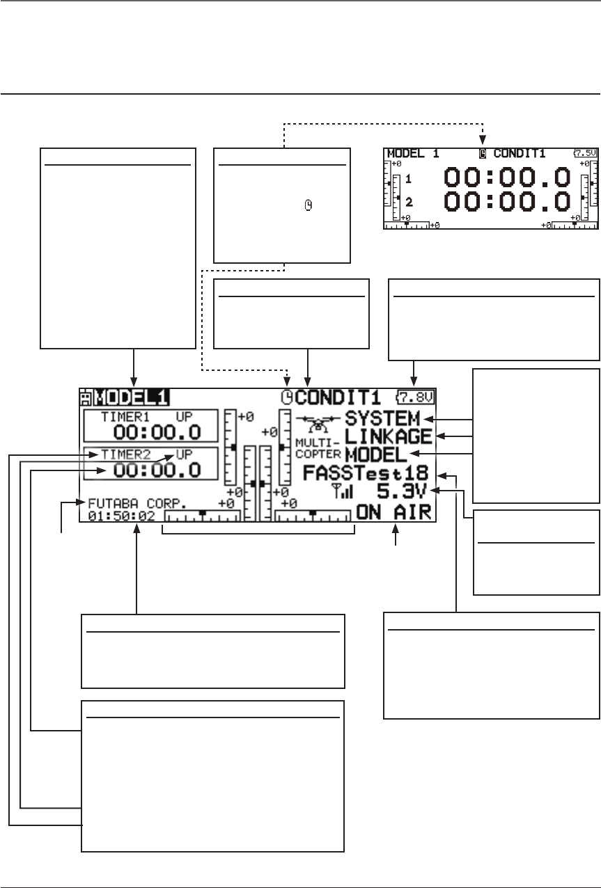
Home screen
Model Name
• The model name that
is currently used is
displayed here.
•The model select
screen can now be
opened directly from
the home screen.
Move the cursor to
the model name on
thehomescreen,
and push the RTN
button.
User's name
Use the edit dial to select the following display area to call each setting screen, and Push the RTN
button. The setting screen appears.
●RFIndicator
●TrimpositionIndicator
Battery Indicator
• When the battery voltage
reaches6.2V,thealarmwill
beep. Land your aircraft
immediately.
Home Screen
Condition Name
• The condition name
that is currently used
is displayed here.
Timer display screen
• When the cursor
is moved to the
clock icon " " of
thehomescreen,
the timer display
screen appears.
System mode
•System(FASSTest18CHetc.)
mode is displayed here.
•Usethecursortohighlightthis,
then push the RTN button to call
the frequency set-up screen.
Battery voltage for
receivers
•Inightreceivers
battery,itis
displayed.
Timer
• Timer is displayed here.
Push the RTN button to start/stop the
timer. (When the RTN button is pushed
for1second,timerisresettotheinitial
value.)
• Mode (UP/DN) is displayed here.
• Push the RTN button to call the timer
setting screen.
System timer
• This shows the accumulated time since
the latest reset. (Each model)
(Hour):(Minute):(Second)
(Menu)
• System
• Linkage
• Model
Push the RTN
button to call
each Menu
screen.
31
<Basic Operation>
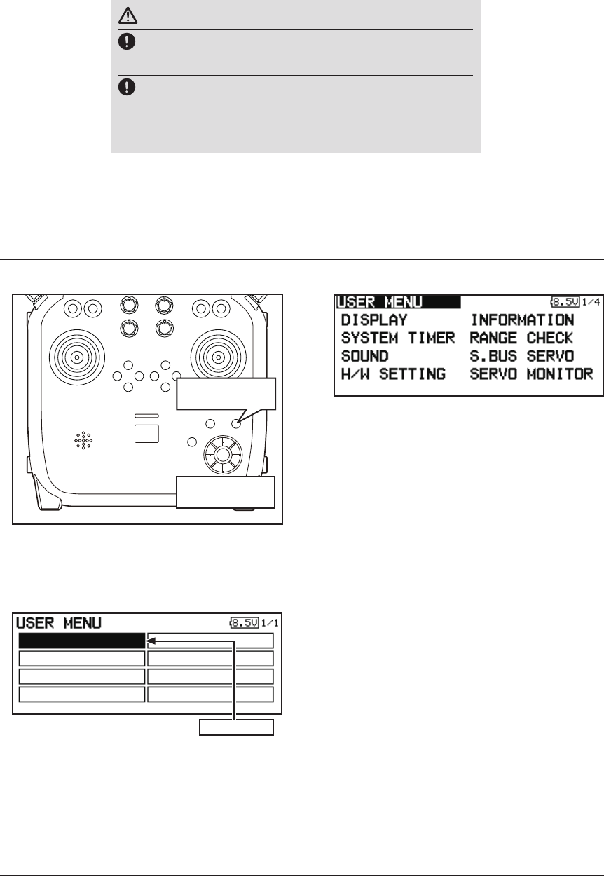
User Menu
WARNING
Be sure to confirm the model name before flying your
aircraft.
Check the battery voltage as often as possible and try to
charge the battery earlier. If the battery alarm makes a
sound, land your aircraft immediately.
*You can adjust the LCD contrast by the display setting in the system menu.
1. When the "U.MENU" button is pushed for
twoseconds,theusermenuappears.
* Return to the home screen by pushing the EXIT button
while the user menu is being displayed.
2.Whenthecursorhighlightsthespacebox,
andtheRTNbuttonispushed,themenu
selection screen appears.
A user menu which allows the user to customize and display frequently used functions has been added.
3. When the cursor is moved to the setting
that you to set to the user menu and the
RTNbuttonispushed,thatsettingscreen
is added to the user menu.
4. The registered setting screen can be
called by moving the cursor to it and
pushing the RTN button.
*When you want to delete an added screen from the user
menu, highlight item you wish to delete, push and hold
the RTN button for one second.
Pushed for two
seconds
U.menu/Mon
Button
32 <Basic Operation>
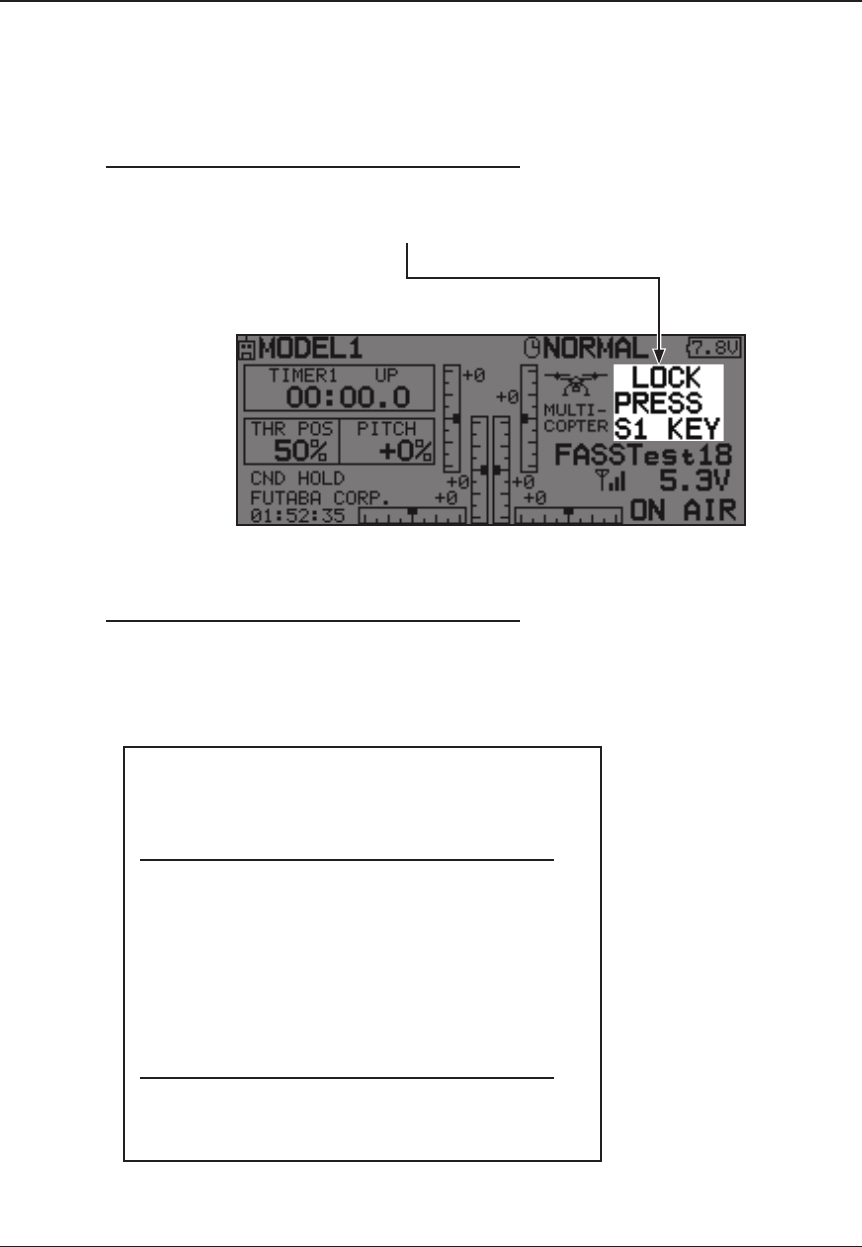
Key lock
To prevent the data from being changed by erroneous pushing of the edit dial during flight, a
function which makes an edit dial impossible temporarily.
How to lock
1. The home screen is displayed.
2. Push the S1 button for about 1 second.
"LOCK" is displayed and the edit dial is
disabled.
How to unlock
1. Push the S1 button for about 1 second in the
edit dial locked state. The edit dial is enabled
again.
STARTUP LOCK
Auto Lock functions automatically when the
model changes or power is turned on.
*To temporarily allow access to the FMT-03 programming
push and hold the S1 bitton for one second. Please note,
the Auto Lock function timer will resume immediately once
again.
*A PIN can also be set to protect the set data.
AUTOMATIC LOCK
Auto Lock functions automatically when there is
no operation from the HOME screen display for a
chosen number of seconds.
*Two kinds of automatic locks can be
chosen by [DISPLAY] of [SYSTEM MENU].
33
<Basic Operation>
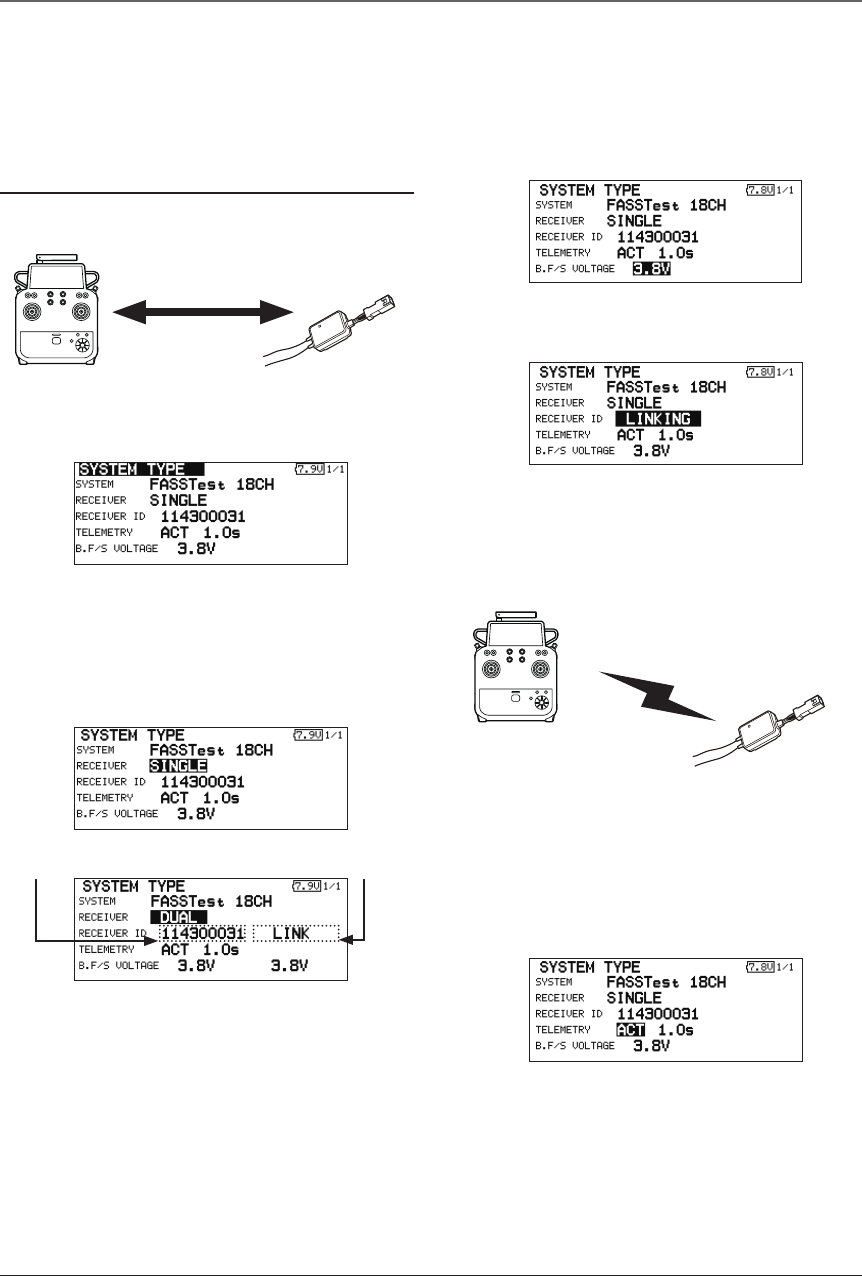
Link procedure (FMT-03 ⇔FMR-03)
Each transmitter has an individually assigned, unique ID code. In order to start operation, the
receiver must be linked with the ID code of the transmitter with which it is being paired. Once the link
is made, the ID code is stored in the receiver and no further linking is necessary unless the receiver is
to be used with another transmitter. When you purchase additional FMR-03 receivers, this procedure is
necessary; otherwise the receiver will not work.
Link procedure
1. Place the transmitter and the receiver close
to each other within half (0.5m) meter.
2. Turn on the transmitter.
3. Select [SYSTEM TYPE] at the Linkage menu
and access the setup screen shown below
by pushing the RTN button.
4.Whenyouusetworeceiversononemodel,
you must change from [SINGLE] to [DUAL].
*Only two receivers can be used. In
"DUAL",twosettingitemscomeout.Input,
respectively.
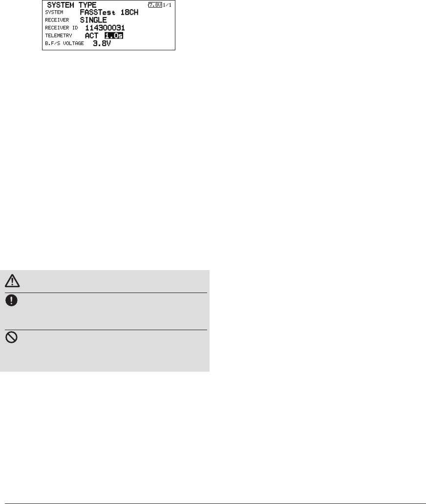
5. When changing battery fail-safe voltage
fromtheinitialvalue3.8V,voltageis
changed here.
6. [RECEIVER-ID] is chosen by scrolling and the
RTN button is pushed. The transmitter will emit
a chime as it starts the linking process.
7.Whenthetransmitterstartstochime,power
on the receiver. The receiver should link to
the transmitter within about 1 second.
8.Iflinkingfails,anerrormessageisdisplayed.
Bring the transmitter closer to the receiver
and repeat the procedure above from Step 2.
9. ACT will be chosen if telemetry is used.
ItisINHwhennotusingit.
Less than 0.5 m
In "Link" Mode
Receiver ON
:You can do this through the LINKAGE Menu
and scroll to System and push RTN.
ID of a primary
receiver displays.
InDUAL,aprimaryreceiver
islinkpreviously.Next,a
secondary receiver is link.
ID of a secondary
receiver displays.
34 <Basic Operation>
10.Whenatelemetryfunctionisenabled,
the receiving interval (down-link interval) of
sensor data can be changed. If a DL interval
isincreased,theresponseofthesensordata
displaybecomesslower,butstickresponse
will improve.
Initial value: 1.0s
Adjustment range: 0.1s~2.0s
* If there are many FASSTest systems turned on around your
receiver, it might not link to your transmitter. In this case,
even if the receiver's LED stays solid green, unfortunately
the receiver might have established a link to one of other
transmitters. This is very dangerous if you do not notice
this situation. In order to avoid the problem, we strongly
recommend you to doublecheck whether your receiver is
really under control by your transmitter by giving the stick
input and then checking the servo response.
*Do not perform the linking operation when the drive motor
is connected or the engine is running.
*When you use two receivers, please be sure to setup a
"primary" and "secondary" in the "dual" mode.
*Telemetry function cannot be used for the 2nd receiver.
* You must link one receiver at a time. If both power
supplies to the receivers are switched on simultaneously,
data is received incorrectly by the transmitter.
* You cannot link three receivers.
* Link is required when a system type is changed.
* Linking is required whenever a new model is made.
WARNING
After the linking is done, please cycle receiver
power and check that the receiver to be linked
is really under the control of the transmitter.
Do not perform the linking procedure with
motor's main wire connected or with the engine
operating as it may result in serious injury.
35
<Basic Operation>
Range Testing Your R/C System
It is extremely important to range check your models prior to each ying session. This enables you
to ensure that everything is functioning as it should and to obtain maximum enjoyment from your time
ying. The FMT-03 transmitter incorporates a system that reduces its power output and allows you to
perform such a range check.
Range check mode
During this mode, the RF power output is reduced
so the range test can be performed. In addition, when
this mode is activated the right LED on the front of the
transmitter starts blinking and the transmitter gives users
a warning with a beeping sound every 3 seconds.
The "Range check mode" continues for 90 seconds
and after that the power will return to the normal level.
To exit the "Range check mode" before the 90 seconds,
select the "EXIT" at the screen and touch the RTN button
again. This mode is available one time only so if you
need to re-use this function the transmitter power must
be cycled. NEVER start flying when the "Range check
mode" is active.
Should you require additional time to perform a range
check, highlight Restart before your time expires and
press the RTN button one time.
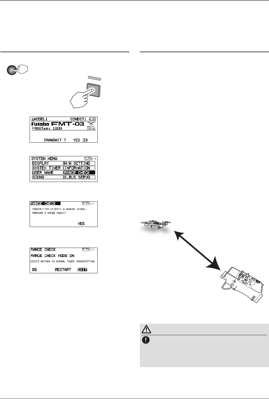
Range check procedure
1.Withthe"Rangecheckmode"on,walk
away from the model while simultaneously
operatingthecontrols.Haveanassistant
stand by the model to confirm that all
controls are completely and correctly
operational. You should be able to walk
approximately 30-50 paces from the model
without losing control.
2.Ifeverythingoperatescorrectly,returnto
themodel.Setthetransmitterinasafe,yet
accessible,locationsoitwillbewithinreach
after starting the engine or motor. Be certain
thethrottlestickisinthelowthrottleposition,
then start the engine or motor. Perform
another range check with your assistant
holding the aircraft with the engine running
at various speeds. If the servos jitter or move
inadvertently,theremaybeaproblem.We
wouldstronglysuggestyoudonotyuntilthe
sourceofthedifcultyhasbeendetermined.
Look for loose servo connections or binding
pushrods.Also,becertainthatthebattery
has been fully charged.
About 100 feet
Range check mode
Range checking on
low power.
Holding the
aircraft.
WARNING
Do not y in the range check mode.
*Since the range of the radio waves is short, if the model
is too far from the transmitter, control will be lost and the
model will crash.
1. While pushing previously "U.menu/Mon" button.
3. Scroll to "NO" and push RTN.
4. "RANGE CHECK" is chosen from
"SYSTEM MENU" and push RTN.
5. "YES" is chosen from "RANGE
CHECK" and push RTN.
2. FMT-03 Power ON.
U.menu/Mon
36 <Basic Operation>
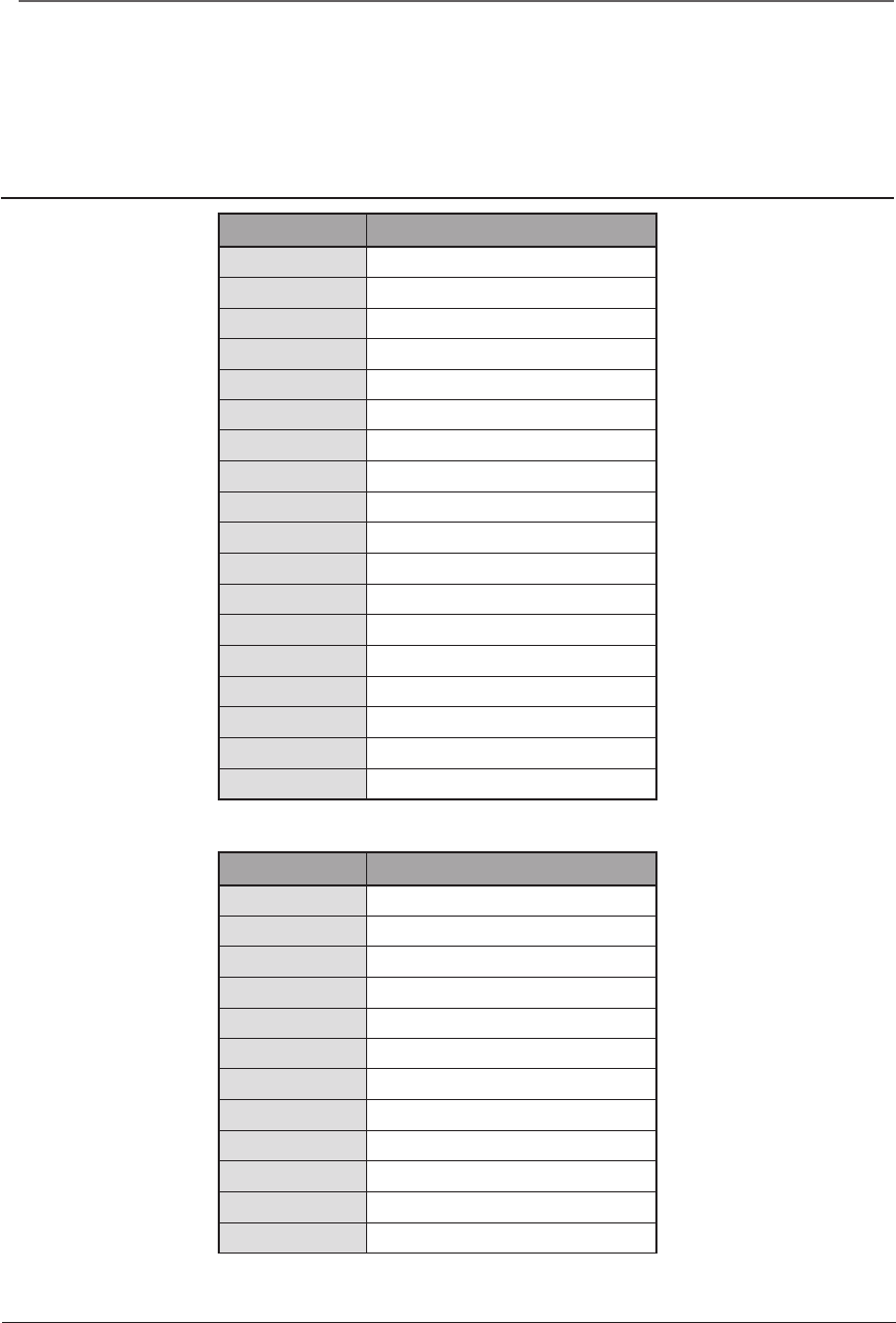
Multicopter
●FASSTest 18CH
●FASSTest 12CH
CH
Multicopter
1 Aileron
2 Elevator
3
Throttle
4
Rudder
5 Gyro
6 Gyro2
7 Gyro3
8CAM TILT
9 CAMERA PAN
10 CAMERA REC
11
Mode
12
AUX5
13
AUX4
14
AUX3
15
AUX2
16
AUX1
DG1
SWSH
DG2
SW SA
CH
Multicopter
1 Aileron
2 Elevator
3
Throttle
4
Rudder
5 Gyro
6 Gyro2
7 Gyro3
8CAM TILT
9 CAMERA PAN
10 CAMERA REC
11
Mode
12
AUX5
Cannels connection by multicopter type
The FMT-03 transmitter channels are automatically assigned for optimal combination according to
the type selected with the Model Type function of the Linkage Menu. The channel assignment (initial
setting) for each model type is shown below. Connect the receiver and servos to match the type used.
*The set channels can be checked at the Function screen of the Linkage Menu. The channel assignments can also be changed.
For more information, read the description of the Function menu.
37
<Functions of System Menu>
SYSTEM MENU
System Menu functions table
[DISPLAY]: LCD contrast and back light adjustment.
[SYSTEM TIMER]: Resets the accumulated timer for each model.
[USER NAME]: User name registration.
[SOUND]: Various volume control and low battery setting.
[H/W SETTING]: H/W reverse, stick mode, stick calibration, and switch position.
[INFORMATION]: Displays the program version, micro SD card information, and language selection.
[RANGE CHECK]: A transmitting output is lowered and the check before a ight is carried out.
[S.BUS SERVO]: S.BUS servo setting.
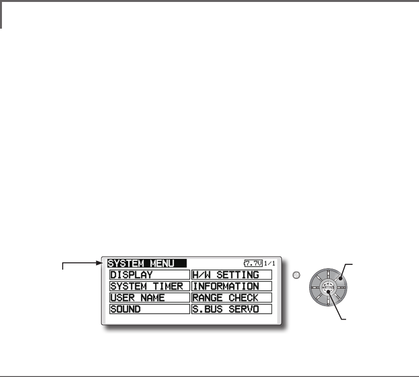
The System Menu sets up functions of the
transmitter: This does not set up any model data.
● Select [SYSTEM] at the home screen and call the system
menu shown below by pushing the RTN button.
● Scrolling the edit dial to select the function you want to set
and call the setup screen by pushing the RTN button.
S1
<Edit dial>
● Select the function name
and return to the System
menu by pushing the RTN
button or pushing the
Home/Exit button.
●Access setup screen
Scrolling
● Moving cursor
38 <Functions of System Menu>
S1
<Edit dial>
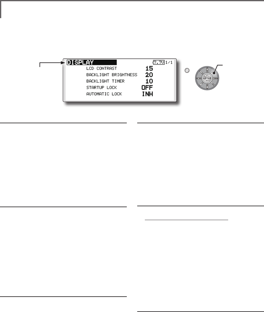
LCD contrast adjustment
1. Scrolling the edit dial to select "LCD CONTRAST"
and push the RTN button to switch to the data
input mode and adjust the contrast by turning the
edit dial to the left and right.
Setting range: (Lighter) 0 to 30 (Darker)
Initial value: 15
Push the RTN button to end adjustment and return
to the cursor move mode.
*Adjust to the contrast while watching the screen display.
*When you want to reset the contrast to the initial state, select
"LCD CONTRAST" and push the RTN button for 1 second.
Backlight brightness adjustment
1. Scrolling the edit dial to select "BACKLIGHT
BRIGHTNESS" and push the RTN button to switch to
the data input mode and adjust the contrast by
turning the edit dial to the left and right.
Setting range: (Darker) 0 to 30 (Lighter)
Initial value: 10
Push the RTN button to end adjustment and return
to the cursor move mode.
*Adjust to the brightness while watching the screen display.
*When you want to reset the contrast to the initial state, select
"BACKLIGHT BRIGHTNESS" and push the RTN button
for 1 second.
Back-light off-timer
1. Select "Back-light timer" and push the RTN button
to switch to the data input mode and adjust the
back-light off-timer by scrolling the edit dial.
"OFF TIMER": Adjust the time when the back-light
turns off after operating the edit dial.
Setting range: 10 to 240 sec (each 10 sec), OFF
(always on)
Initial value: 10 sec
*When you want to reset the value to the initial state, push
the RTN button for one second.
2. Push the RTN button to end adjustment and
return to the cursor mode.
*If the back light is on for a long time, consumption current
will increase.
DISPLAY LCD contrast adjustment and automatic key lock
The following LCD screen adjustments and auto
power off setting are possible:
● Backlighting brightness adjustment
● Backlighting off timer adjustment
● Key lock setup
Start lock
Auto Lock functions automatically when the
model changes or power is turned on.
*To temporarily allow access to the FMT-03 programming
push and hold the S1 button for one second. Please note,
the Auto Lock function timer will resume immediately once
again.
1. Select "STARTUP LOCK" and push the RTN button to
switch to the data input mode and adjust the ON
or OFF by scrolling the edit dial.
Setting range: ON or OFF
Initial value: OFF
Set PIN ID
A PIN can also be set to protect the set data.
*Please do not forget the ID you set here. You have to input
the ID in order to unlock the ID lock on the home screen.
If you do not need the ID lock feature, please set the ID for
"00000000".
1. Select "ID" and push the RTN button to switch to the
ID input screen.
2. Scrolling the edit dial to select "00000000" and push
the RTN button to switch to the data input mode
and adjust the number by turning the edit dial
to the left and right. Push the RTN button to end
adjustment and return to the cursor move mode.
3. UNLOCK: Push the S1 button for about 1 second
in the edit dial locked state. And input the ID you
have set. The edit dial is enabled again.
Automatic lock
Auto Lock functions automatically when there is
no operation from the HOME screen display for a
chosen number of seconds.
1. Scrolling the edit dial to select "AUTOMATIC LOCK"
and push the RTN button to switch to the data
input mode and adjust the time by turning the edit
dial to the left and right.
Setting range: INH, 0 to 120 (s)
Initial value: INH
● Select [DISPLAY] at the system menu and call the setup
screen shown below by pushing the RTN button.
● Select the function name
and return to the System
menu by pushing the RTN
button or pushing the
Home/Exit button.
Scrolling
● Moving cursor
● Selecting mode
● Adjusting value
A PIN can also be set to protect the set data.
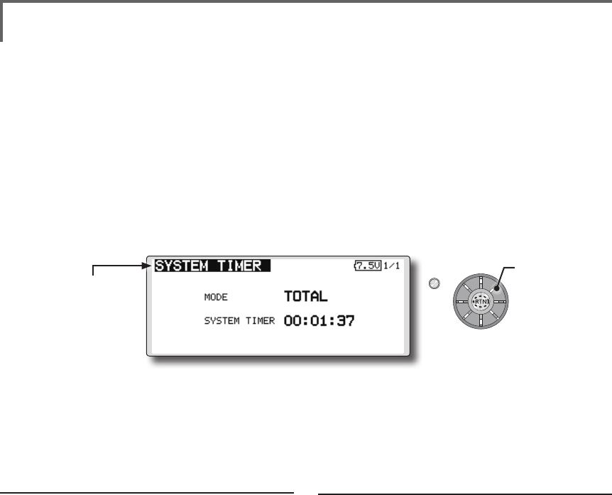
39
<Functions of System Menu>
S1
<Edit dial>
● Select the function name
and return to the System
menu by pushing the RTN
button or pushing the
Home/Exit button.
Timer selection
1. Move the cursor to the [MODE] item and
push the RTN button to switch to the data
input mode.
Select the mode by scrolling the edit dial
and push the RTN button.
TOTAL: Displays the total timer on the home
screen.
MODEL timer: Displays the model timer on
the home screen.
SYSTEM TIMER Resets the accumulated timer.
This function resets the system timer displayed
on the home screen.
● FMT-03 has two type system timers.
TOTAL timer: Displays the total accumulated
time on the transmitter from the last time the
timer was reset.
MODEL timer: Displays the total accumulated
time on each model from the last time the
timer was reset.
● System timer displayed on the home screen
can be selected.
● Select [SYSTEM TIMER] at the system menu and call the
setup screen shown below by pushing the RTN button.
Timer reset
1. Move the cursor to the [SYSTEM TIMER] item
and reset the timer to "00:00:00" by pushing
the RTN button for 1 second. After reset, the
timer restarts from "00:00:00".
Scrolling
● Moving cursor
● Selecting mode
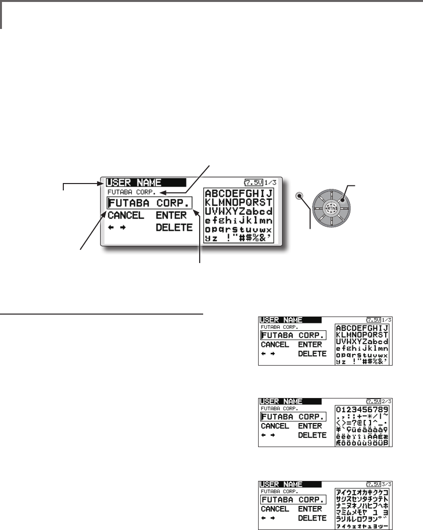
40 <Functions of System Menu>
S1
<Edit dial>
● Select the function name
and return to the System
menu by pushing the RTN
button or pushing the
Home/Exit button.
USER NAME User name registration
This function registers the FMT-03 user name.
*A name of up to 12 characters can be entered as the user
name. (Space is also counted as 1 character.)
User name registration
1. Change the user name as described below:
[Moving cursor in input box]
Select [←] or [→], and push the RTN button.
[Deleting a character]
When [DELETE] is selected and the RTN
button is pushed, the character immediately
after the cursor is deleted.
[Adding a character]
When a candidate character is selected
from the character list and the RTN button
is pushed, that character is added at the
position immediately after the cursor.
*A name of up to 12 characters long can be entered as the
user name. (A space is also counted as 1 character.)
2. At the end of input, select [ENTER] and push
the RTN button. (To terminate input and
return to the original state, select [CANCEL]
and push the RTN button.)
(Character list 1/3)
(Character list 2/3)
(Character list 3/3)
● Select [USER NAME] at the system menu and call the
setup screen shown below by pushing the RTN button.
● Push the S1 button to
call next page.
Scrolling
● Moving cursor
Current user name
Input box
Cursor (blink)
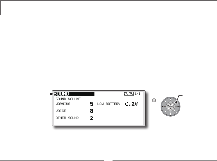
41
<Functions of System Menu>
S1
<Edit dial>
● Select the function name
and return to the System
menu by pushing the RTN
button or pushing the
Home/Exit button.
3 independent sound volumes: "WARNING",
"VOICE" and others, are available.
"LOW BATTERY" adjusts low battery alarm
voltage to match a battery.
● Select [SOUND] at the system menu and access the
setup screen shown below by pushing the RTN button.
Sound volume operation
1. Move the cursor to the [WARNING][VOICE]
or [OTHER SOUND] item and push the RTN
button to switch to the data input mode.
2. Select the volume by scrolling the edit dial.
*The display blinks.
3. Push the RTN button.
Low battery voltage operation
1. Move the cursor to the [LOW BATTERY] item
and push the RTN button to voltage to the
data input mode.
2. Select the voltage by scrolling the edit dial.
*The display blinks.
3. Push the RTN button.
SOUND Turns off the buzzer.
Scrolling
● Moving cursor
● Adjusting value
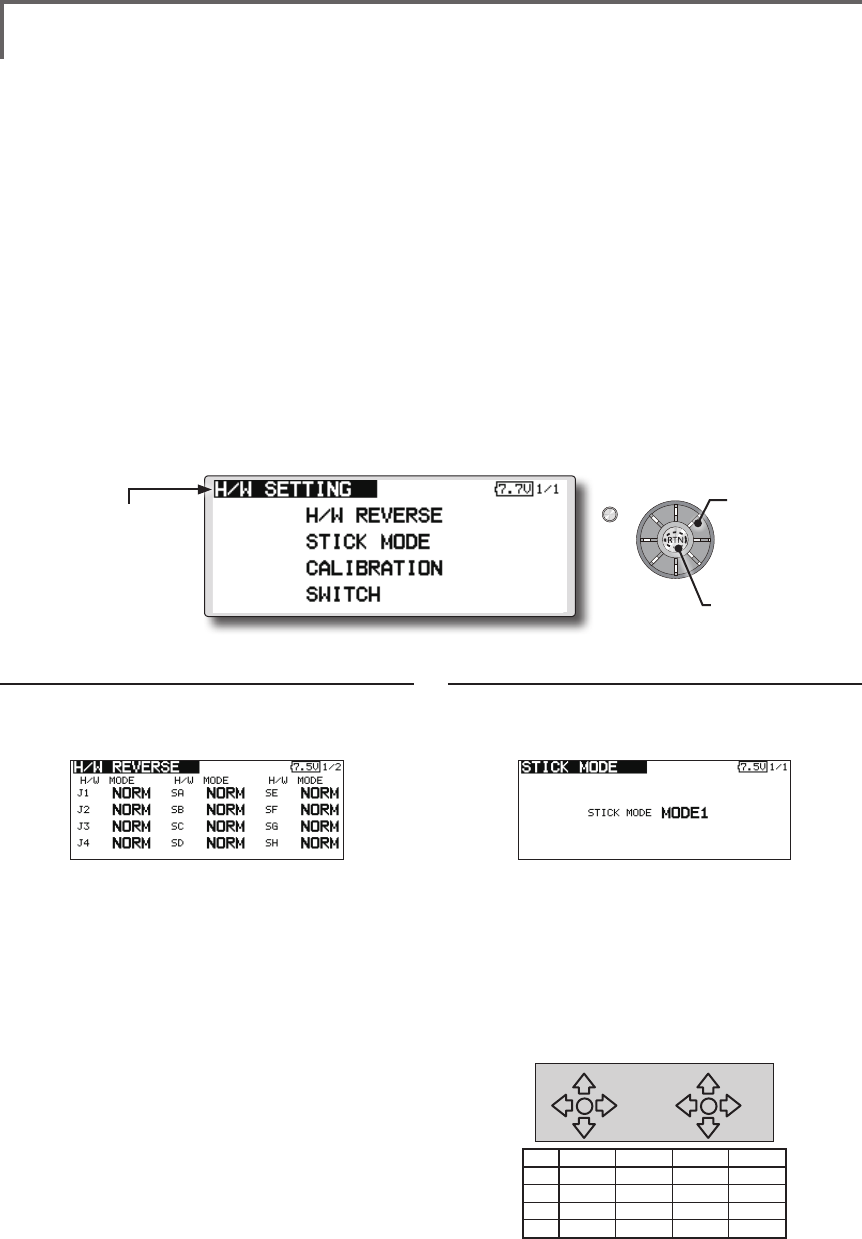
42 <Functions of System Menu>
S1
● Select the function name
and return to the System
menu by pushing the RTN
button or pushing the
Home/Exit button.
<Edit dial>
Operation direction reversal method
1. Select [H/W REVERSE] and call the setup
screen shown below by pushing the RTN
button.
2. Use the edit dial to move the cursor to the
"MODE" item corresponding to the H/W
(hardware) you want to reverse and push
the RTN button to switch to the data input
mode.
3. Change the mode by turning the edit dial to
the left or right. The display blinks. When the
RTN button is pushed, the operation direction
is reversed. (To terminate mode change, turn
the edit dial or push the S1 button.)
"NORM": Normal operation direction
"REV" : Operation direction is reversed.
H/W SETTING Hardware reverse and stick mode, stick calibration, switch position
H/W reverse
This function reverses the operation signal of the
sticks, switches, trimmer levers, and knobs.
Note: This setting reverses the actual operation
signal, but does not change the display of
the indicators on the display. Use the Normal
mode as long as there is no special reason to
use the Reverse mode.
Stick mode
This function changes the stick mode of
transmitter.
Note: This will not change the throttle ratchet,
etc. Those are mechanical changes that
must be done by a Futaba service center.
Note: After changing the mode, it is applied
when setting a new model. It is not applied
to an existing model.
Stick calibration
J1-J4 stick correction can be performed.
Note: It does not carry out, when there is no
necessity.
Switch
For set the switch type and position amount
when the stock conguration is changed.
● Select [H/W SETTING] at the system menu and call the
setup screen shown below by pushing the RTN button.
Operation direction reversal method
1. Select [STICK MODE] and call the setup
screen shown below by pushing the RTN
button.
2. Use the edit dial to move the cursor to the
"STICK MODE" item and push the RTN button
to switch to the data input mode.
3. Change the mode by turning the edit dial
to the left or right. The display blinks. When
the RTN button is pushed, the stick mode is
changed. (To terminate mode change, turn
the edit dial or push the S1 button.)
(J1)
(J2)
(J4)
(J3)
Mode J1 J2 J3 J4
1Aileron Throttle Elevator Rudder
2 Aileron Elevator Throttle Rudder
3 Rudder Throttle Elevator Aileron
4 Rudder Elevator Throttle Aileron
●Access setup screen
Scrolling
● Moving cursor
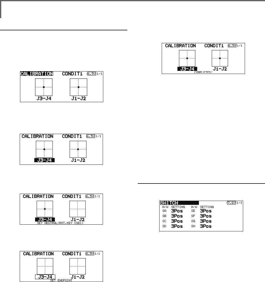
43
<Functions of System Menu>
Operation switch setting method
1. Select [SWITCH] and call the setup screen
shown below by pushing the RTN button.
2. Use the edit dial to move the cursor to the
"SA-SH" item corresponding to the switch you
want to change and push the RTN button to
switch to the data input mode.
3. Change the "2Pos" or "3Pos" by turning the
edit dial to the left or right. The display blinks.
It will decide, if the RTN button is pushed. (To
terminate mode change, turn the edit dial or
push the S1 button.)
"3Pos": 3 position switch
"2Pos" : 2 position switch
Stick calibration method
*J3-J4 correction is described below. J1-J2 corrections are
performed using the same procedure.
1. Select [CALIBRATION] and access the setup
screen shown below by pushing the RTN
button.
2. Move the cursor to the J3-J4 button and push
the RTN button.
3. Move the J3-J4 stick to the neutral position
and push the RTN button for one second.
4. Set the J3-J4 stick fully to the bottom- right
and wait until the buzzer sounds.
5. Set the J3-J4 stick fully to the top-left and
wait until the buzzer sounds.
6. The above completes the correction
operation. Operate and check if stick
correction was performed normally.
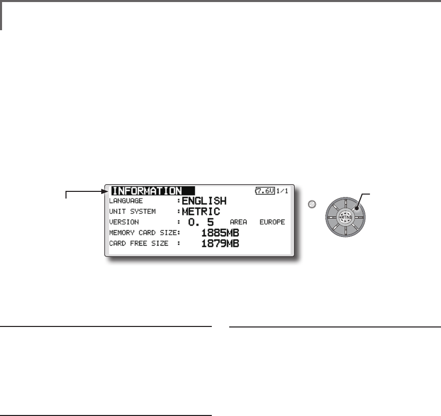
44 <Functions of System Menu>
S1
<Edit dial>
● Select the function name
and return to the System
menu by pushing the RTN
button or pushing the
Home/Exit button.
Displays the program version, Micro SD card information, and product
ID.
The FMT-03 system program version
information, micro SD card information (maximum
and vacant number of model data), and product ID
are displayed on the Information screen.
*When the micro SD card is not inserted, the micro SD card
information is not displayed.
The language displayed in home, menu, and
setup screen is selectable.
Also, the unit of a telemetry display can also be
changed.
● Select [INFORMATION] at the system menu and call the
setup screen shown below by pushing the RTN button.
Information
"VERSION": FMT-03 system program version
information
"MEMORY CARD SIZE": Maximum number of
model data (Micro SD card)
"CARD FREE SIZE": Vacant number of model
data (Micro SD card)
Language selection
1. Use the edit dial to move the cursor to the
"LANGUAGE" item and push the RTN button
to switch to the data input mode.
2. Change the language by turning the edit dial
to the left or right. The display blinks. When
the RTN button is pushed, the language is
changed. (To terminate mode change, turn
the edit dial or push the S1 button.)
Unit system selection
1. Use the edit dial to move the cursor to the
"UNIT SYSTEM" item and push the RTN button
to switch to the data input mode.
2. Change the unit by turning the edit dial to
the left or right. The display blinks. When the
RTN button is pushed, the unit is changed. (To
terminate mode change, turn the edit dial or
push the S1 button.)
INFORMATION
Scrolling
● Moving cursor
● Selecting mode
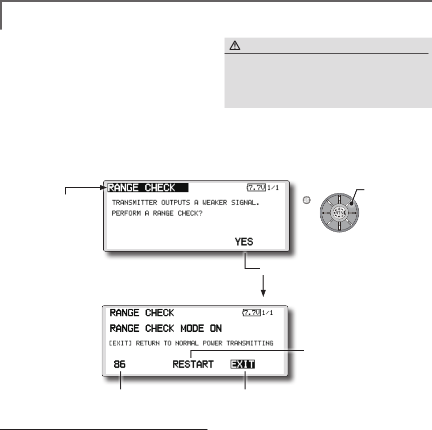
45
<Functions of System Menu>
S1
<Edit dial>
● Select the function name
and return to the System
menu by pushing the RTN
button or pushing the
Home/Exit button.
RANGE CHECK Before a ight ground range check.
The 'range check mode' reduces the transmission
range of the radio waves to allow for a ground
range check.
*The range check mode, when activated, will continue for
90 seconds unless the user exits this mode early. When the
progress bar reaches 90 second mark, the RF transmission
automatically returns to the normal operating power.
● Pushing [U.menu/Mon] button is continued. →Turn ON the transmitter's power switch.
(First, a throttle stick is made into a low position, and turns on a power supply.) It is
displayed as "TRANSMIT?". "NO" is chosen and [RTN] is pushed.
● [Yes] is chosen and [RTN] is pushed.
● Remaining time of
RANGE CHECK MODE.
● Range Check mode is
disabled.
● Range Check mode
timer is returned to 90.
Rotation Range Check method
1. Pushing [U.menu/Mon] button is continued.
→Turn ON the transmitter's power switch.
(First, a throttle stick is made into a low
position, and turns on a power supply.)
It is displayed as "TRANSMIT?."
"NO" is chosen and [RTN] is pushed.
*For safety, the RANGE CHECK mode can not be selected
while the RF transmission is active.
2. In the system menu, choose the 'Range
Check' selection from the menu options.
3. The Range Check screen is displayed. To
activate the Range Check mode push
the [Yes] button. During the Range Check
period, the RF power is reduced to allow the
ground range tests to be performed.
4. The Range Check function automatically
exits after the 90 second time limit has
expired. The count down time is displayed on
the transmitter's screen. Should you complete
the range check before the 90 seconds has
pushed, push the [Exit] button.
*When the [RESTART] button is pushed, the range check
mode timer is returned to 90.
*Please note, upon expiration of the 90 seconds, or when
[Exit] is selected, the transmitter will automatically return to
the normal RF operation as noted on the display.
*Once the FMT-03 is transmitting at full power, it is not
possible to enter the Range Check mode without first
switching the transmitter Off and back On. This has been
designed to prevent a modeler from inadvertently ying in
the Range Check mode.
5. When the [Exit] button is pushed, the Range
Check mode is disabled and the FMT-03 will
begin transmitting at full power.
*After exiting the Range Check mode, the function cannot be
selected again. To select the Range Check mode again you
must cycle the transmitter power switch.
● Select [RANGE CHECK] at the system menu and call the setup screen shown below by
pushing the RTN button.
WARNING
Do not y in the range check mode.
■Since the range of the radio waves is short, if the model
is too far from the transmitter, control will be lost and the
model will crash.
Scrolling
● Moving cursor
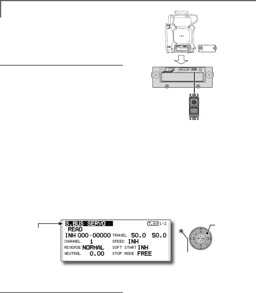
46 <Functions of System Menu>
S1
● Select the function name
and return to the System
menu by pushing the RTN
button or pushing the
Home/Exit button.
<Edit dial>
Procedure for changing S.BUS/S.BUS2 servo
setting
1. Select [S.BUS Servo] of the System Menu.
2. Wire the servo as shown in the gure above.
3. Push [READ]. The ID and current setting of
that servo are displayed.
4. When multiple servos are connected change
[INH] at the right side of the ID number on the
screen to [ACT] and enter the ID of the servo
you want to set.
5. Set each item. (Please see the next page.)
6. Push [WRITE]. The settings are changed.
S.BUS SERVO
An S.BUS/S.BUS2 servo can memorize the
channel and various settings internally. Servo
setting changes can be performed on the FMT-03
screen by wiring the servo as shown in the gure.
● Call the following setting screen by pushing the
[S.BUS Servo] button in the System Menu.
●Servo ID number
Individual ID numbers are memorized for your
S.BUS servos in your FMT-03. When a servo is
used (as shown at the right), the servo ID number is
automatically read by the transmitter.
If you use multiple S.BUS servos and do not
want to change the settings on all that are mounted
in a fuselage, only the desired servo in the group
can be set by entering the ID of that specic servo.
* With S.BUS/S.BUS2 servos of use, there are a function which
can be used, and an impossible function and a display screen
changes.
(Only the function which can be used by a servo is displayed.)
* After reading completion, with connection of the above
gure, if a stick is moved, the test of operation of the servo
can be operated and carried out.
S.BUS/S.BUS2 servo
FMT-03
*It is not necessary to carry out multiple connection of the
battery like a T18MZ/T14SG.
(It will damage, if it connects.)
Scrolling
● Moving cursor
● Push the S1 button to
call next page.
*When you connect to a transmitter with many servos which
may consume extra current, please use "Another power
supply HUB". And ensure power is supplied to extra servos
with another power supply.

47
<Functions of System Menu>
S.BUS Servo Description of function of each parameter
*There are some functions which can only be used with certain types of servos.
• ID
Displays the ID of the servo whose parameters are to be read. It cannot be changed.
• Channel
Channel of the S.BUS system is assigned to the servo. Always assign a channel before use.
• Reverse
The direction in which the servo rotates can be changed.
• Servo type
When “Retractable” is selected and the servo has been continuously stopped for 30 seconds, the dead
band expands and unnecessary hold current due to external force is eliminated. When a new control
signal enters, normal operation is resumed. When using the servo as a landing gear servo, select
“Retractable”. Also adjust the servo travel to match the landing gear movement range.
• Soft Start
Restricts operation in the specified direction the instant the power is turned on. By using this setting, the
first initial movement when the power is turned on slowly moves the servo to the specified position.
• Stop Mode
The state of the servo when the servo input signal is lost can be specified. The "Hold" mode setting holds
the servo in its last commanded position even if using AM or FM system.
• Smoother
This function changes smoothness of the servo operation relative to stick movement changes. Smooth
setting is used for normal flight. Select the "OFF" mode when quick operation is necessary such as 3D.
• Neutral Offset
The neutral position can be changed. When the neutral offset is large value, the servo's range of travel is
restricted on one side.
• Speed Control
Speeds can be matched by specifying the operating speed. The speed of multiple servos can be matched
without being affected by motor fluctuations. This is effective for load torques below the maximum torque.
However, note that the maximum speed will not be exceed what the servo is capable of even if the servos
operating voltage is increased.
• Dead band
The dead band angle at stopping can be specified.
[Relationship between dead band set value and servo operation]
Small → Dead band angle is small and the servo is immediately operated by a small signal change.
Large → Dead band angle is large and the servo does not operate at small signal changes.
(Note) If the dead band angle is too small, the servo will operate continuously and the current
consumption will increase and the life of the servo will be shortened.
• Travel Adjust
The left and right travels centered about the neutral position can be set independently.
• Boost
The minimum current applied to the internal motor when starting the servo can be set. Since a small
travel does not start the motor, it essentially feels like the dead band was expanded. The motor can be
immediately started by adjusting the minimum current which can start the motor.
[Relationship between boost set value and servo operation]
Small → Motor reacts less to a change and operation becomes smooth.
Large → Initial response improves and output torque increases. However, if the torque is too large,
operation will become rough.

48 <Functions of System Menu>
• Boost ON/OFF
OFF : The boost turns ON at the time of lower-demand operation. (In most cases)
ON : The boost is always ON. (When quick operation is needed)
• Damper
The characteristic when the servo is stopped can be set.
When smaller than the standard value, the characteristic becomes an overshoot characteristic. If the value
is larger than the standard value, the brake is applied before the stop position.
Especially, when a large load is applied, overshoot, etc. are suppushed by inertia and hunting may occur,
depending on the conditions. If hunting (phenomena which cause the servo to oscillate) occurs even
though the Dead Band, Stretcher, Boost and other parameters are suitable, adjust this parameter to a
value larger than the initial value.
[Relationship between damper set value and servo operation]
Small → When you want to overshoot. Set so that hunting does not occur.
Large → When you want to operate so that braking is not applied. However, it will feel like the servo
response has slowed down.
(Note) If used in the hunting state, not only will the current consumption increase, but the life of the servo
will also be shortened.
• Stretcher
The servo hold characteristic can be set. The torque which attempts to return the servo to the target
position when the current servo position has deviated from the target position can be adjusted.
This is used when stopping hunting, etc., but the holding characteristic changes as shown below.
[Relationship between stretcher and servo operation]
Small → Servo holding force becomes weaker.
Large → Servo holding force becomes stronger.
(Note) When this parameter is large, the current consumption increases.
• Buzzer
When the power supply of a servo is interrupted or a loss of signal from the transmitter, the buzzer sound
of about 2.5Hz continues sounding from a servo.
(Even when the signal output of a transmitter is lost, a buzzer becomes until the signal of a servo is
outputted normally.)
The transmitter has been turned OFF ahead of a servo power supply → The buzzer sound of about 1.25
Hz continues sounding to show that the servo power supply is still turned on.
(Do not insert or remove the servo connector while the receiver power is ON. A buzzer may
sound by incorrect recognition.)
*Buzzer sound is generated by vibrating the motor of a servo.
Since a lot of current is consumed and a servo generates heat during buzzer sounds, please do not
operate the feature more than needed or do not continue sounding a buzzer for a long time.
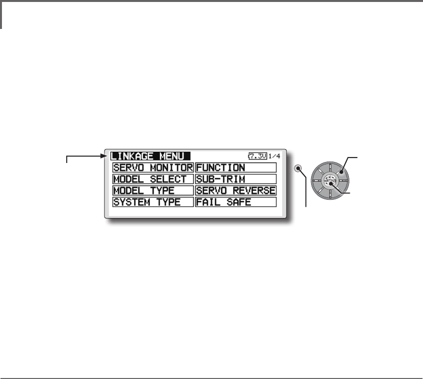
49
<Functions of Linkage Menu>
FUNCTIONS OF LINKAGE MENU
The Linkage Menu is made up of functions
which perform model addition, model type
selection, frequency setting, end point setting, and
other model basic settings.
The functions which can be selected depend on
the model type. A typical menu screen is shown
below.
Linkage Menu functions table
[SERVO MONITOR]: Displays the servo test and operation position
[MODEL SELECT]: Model addition, call, deletion, copy, model name setting
[MODEL TYPE]: Model type, wing type, swash type, etc. selection
[SYSTEM TYPE]: System mode selection, link of a transmitter and receiver, area mode selection
[FUNCTION]: Channel assignment of each function can be changed
[SUB-TRIM]: Adjusts the neutral position of each servo
[SERVO-REVERSE]: Servo direction reversal
[FAIL SAFE]: Fail safe function and battery fail safe function setting
[END POINT]: Servo basic rudder adjustment and limit setting
[THROTTLE CUT]: Stops the engine safely and easily (airplane and helicopter only)
[IDLE DOWN]: Lowers the idle speed of the engine (airplane and helicopter only)
[TIMER]: Timer setting
[T1-T6 SETTING]: Control step amount and mode selection of the digital trim
[MULTIPROP]: CH is extended by MPDX-1 of an option
[FUNCTION NAME]: Function name can be changed
[TELEMETRY]: Displays various data sent from the receiver
[SENSOR]: Various telemetry sensors setting
[TELE.SETTING]: Various telemetry sensors setting
[WARNING]: Mixing warning normal reset
[TRAINER]: Starts and sets the trainer system.
[STICK ALARM]: Can be set so that an audible alarm sounds once when the throttle stick reaches the set position
[DATA RESET]: Model memory set data reset (by item)
● Select [LINKAGE] at the home screen and call the
linkage menu shown below by pushing the RTN button.
● Use the edit dial to select the function you want to set
and call the setup screen by pushing the RTN button.
S1
● Select the function name
and return to the Linkage
menu by pushing the RTN
button or pushing the
Home/Exit button. ●Calling setup screen
Scrolling
● Moving cursor
● Push the S1 button
to call next page.
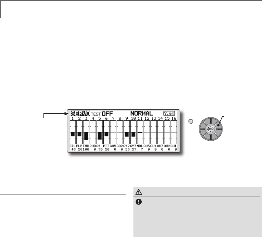
50 <Functions of Linkage Menu>
S1
<Edit dial>
● Select the function name
and return to the Linkage
menu by pushing the RTN
button or pushing the
Home/Exit button.
WARNING
Don't set a servo test mode when the drive
motor is connected and the engine is powered
or running.
■Inadvertent rotation of the motor or acceleration of the
engine is extremely dangerous.
SERVO MONITOR Servo Test & Graph Display / Displays servo positions.
This is used for testing servo movement.
“Moving Test” (repetition mode) and “Neutral
Test” (xed position mode) are available.
The “Neutral Test” is good for finding the
neutral position of a servo horn.
In order to prevent any potential difficulties,
the servo test function will be inoperable, or
inaccessible, under certain conditions. Specically,
the Servo Test function is not operational if the
Throttle Cut is ON in either airplane or helicopter
modes; or if the Throttle Hold is ON in Helicopter
mode.
● Select [SERVO MONITOR] at the linkage menu and call the
setup screen shown below by pushing the RTN button.
Servo test operation
1. Use the edit dial to move the cursor to the
[TEST] item and push the RTN button to switch
to the data input mode.
Select the test mode by turning the edit dial
to the left or right and push the RTN button.
[MOVING]: Mode which repeats operation of
each servo
[NEUTRAL]: Mode which locks each servo in
the neutral position
2. Use the edit dial to move the cursor to the
[TEST] item and push the RTN button to switch
to the data input mode.
Select the [OFF] by turning the edit dial and
push the RTN button. Testing is stopped.
*The display screen is an example. The screen
depends on the model type.
Scrolling
● Moving cursor
● Selecting mode
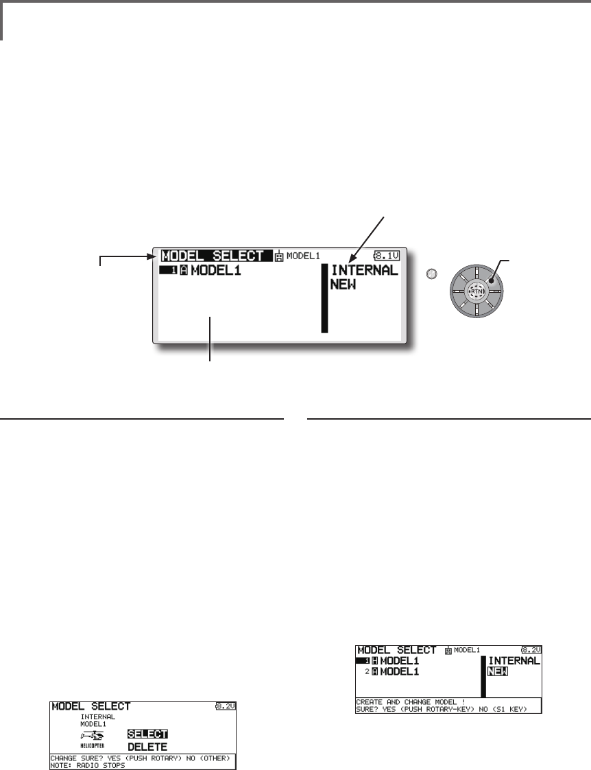
51
<Functions of Linkage Menu>
S1
<Edit dial>
● Select the function name
and return to the Linkage
menu by pushing the RTN
button or pushing the
Home/Exit button.
MODEL SELECT The Model Selection function performs model addition, call,
deletion, copy, and model name setting.
This function is used to load the settings of the
desired model into the FMT-03’s memory.
The settings may be selected from either the
transmitter’s built-in memory or a micro SD card.
Remember that up to 30 model memories are
available in the transmitter.
The name of the model stored in the transmitter
and the micro SD card may be changed. This can
be very useful to tell different models settings apart.
Each model name can be as long as 15 characters,
and the model name always appears in the display
screen. The Copy function is used to copy one set
of model data into a second memory within the
transmitter and the micro SD card. It may be used
for getting a head-start on setting up models with
almost the same settings (only differences need to
be modied, instead of entering the complete model
from scratch). Also, this function may be used to
make a backup copy of a model setup before any
changes are made.
Model call
*Model data saved at models other than the model currently
used or saved on a Micro SD card can be called.
1. Use the edit dial to move to the save
destination ("INTERNAL" or "MEM.CARD") and
push the RTN button to switch to the data
input mode.
Select the location which is to save the
desired model by turning the edit dial to the
left or right. Push the RTN button.
[INTERNAL]: Transmitter memory
[MEM. CARD]: Micro SD card
2. After using the edit dial to move the cursor to
the desired model in the model list, push the
RTN button.
3. Use the edit dial to move to [SELECT].
4. Push the RTN button. When a confirmation
message is displayed and the RTN button is
pushed again, calling is complete.
*Transmission stops and a send with new model conrmation
message ("TRANSMIT?") appears.
5. To start transmission, use the edit dial to
select [YES] and then push the RTN button.
To not transmit, select [NO] and push the RTN
button.
Model addition
*A new model can be added to the transmitter memory or
Micro SD card.
1. Use the edit dial to move the cursor to the
save destination ("INTERNAL" or "MEM. CARD)
and push the RTN button to switch to the
data input mode.
Select the save destination by turning the
edit dial to the left or right. Push the RTN
button.
[INTERNAL]: Transmitter memory
[MEM. CARD]: Micro SD card
2. Use the edit dial to move to [NEW].
3. Push the RTN button. A conrmation message
appears. Push the RTN button again.
*The model type setup screen and frequency setup screen are
automatically displayed. Conrm or change the model type
and frequency.
*A starting transmission with new model confirmation
message ("TRANSMIT") appears.
4. To start transmission, use the edit dial to
select [YES] and then push the RTN button.
To not transmit, select [NO] and push the RTN
button.
*The added model appears in the model list.
● Select [MODEL SELECT] at the linkage menu and call the
setup screen shown below by pushing the RTN button.
*The display screen is an example. The screen
depends on the model type.
(Model list)
●"Save to"
[INTERNAL]: transmitter memory
[MEM.CARD]: Micro SD card
Scrolling
● Moving cursor
● Selecting mode
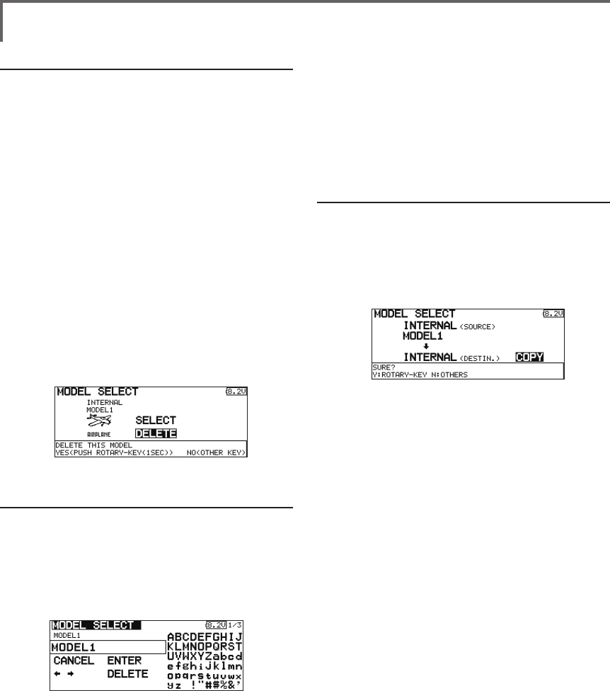
52 <Functions of Linkage Menu>
Model deletion
*The model stored in the transmitter memory or a Micro SD
card can be deleted.
*The current model can not be deleted.
1. Use the edit dial to move the cursor to the
save destination display ("INTERNAL" or "MEM.
CARD") and push the RTN button to switch to
the data input mode.
Select the save destination by turning the
edit dial to the left or right and push the RTN
button.
[INTERNAL]: Transmitter memory
[MEM. CARD]: Micro SD card
2. Use the edit dial to move the cursor to the
model you want to delete in the model list
and then push the RTN button.
3. Move the cursor to [DELETE].
4. Push the RTN button. When a confirmation
message is displayed and the RTN button is
pushed again, the model is deleted.
Model name change
*The current model's name can be changed.
1.Use the edit dial to select the current model in
the model list and then push the RTN button.
2. Use the edit dial to move to [RENAME].
3. Push the RTN button.
*The model name setup screen is displayed.
4. Change the model name as described
below:
[Moving cursor in input box]
Select [←] or [→], and push the RTN button.
[Deleting a character]
When [DELETE] is selected and the RTN
button is pushed, the character immediately
after the cursor is deleted.
[Adding a character]
When a candidate character is selected
from the character list and the RTN button
is pushed, that character is added at the
position immediately after the cursor.
*A name of up to 8 characters long can be entered as the
model name. (A space is also counted as 1 character.)
5. At the end of input, select [ENTER] and push
the RTN button. (To terminate input and
return to the original state, select [CANCEL]
and push the RTN button.)
Model copy
*A copy can be made of the current model.
1.Use the edit dial to select the current model in
the model list and then push the RTN button.
2. Move to [COPY] with the edit dial.
3. Push the RTN button.
*The copy screen appears.
4. Use the edit dial to move to the copy
destination position at the bottom of the
screen and push the RTN button to switch to
the data input mode.
Select the save destination by turning the
edit dial and push the RTN button.
5. Use the edit dial to move to [COPY].
6. Push the RTN button. When a confirmation
message is displayed and the RTN button is
pushed again, the model data is copied.
*FMT-03 accepts a Micro SD card formatted FAT le system,
but it does not supports the long le name feature used in
Windows or other modern operating systems. Thus FMT-
03 can accept les whose name consists of only 8 characters
or less. Furthermore, it supports only basic alphanumeric
characters such as 'A" to 'Z", '0' to '9' and '_'.
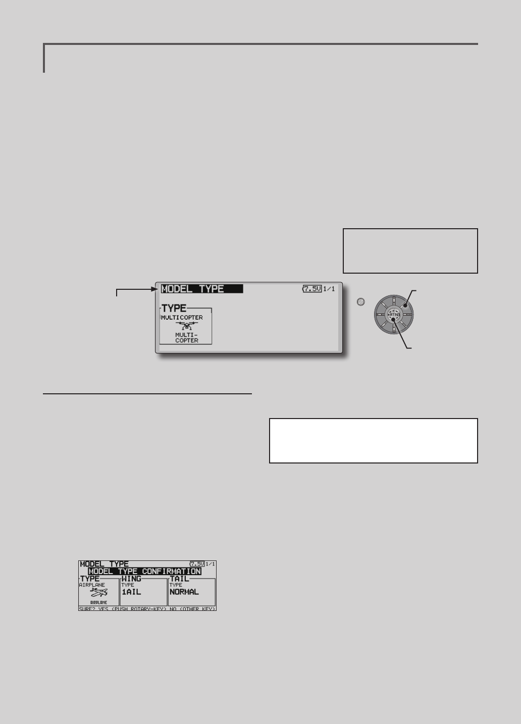
53
<Functions of Linkage Menu>
S1
● Select the function name
and return to the Linkage
menu by pushing the RTN
button or pushing the
Home/Exit button.
<Edit dial>
MODEL TYPE This function selects the model type from among multicopter,
airplane, helicopter, and glider.
(The display screen is an example. The screen
depends on the model type.)
Seven types of main wings and three types
of tail wings are available for airplanes. Eight
swash types are available for helicopters. Seven
types of main wings and three types of tail wings
are available for gliders. Functions and mixing
functions necessary for each model type are set in
advance at the factory.
Note:
The Model Type function automatically selects
the appropriate output channels, control functions,
and mixing functions for the chosen model type.
When the Model Type Selection command is
accessed, all of the data in the active memory is
cleared (except the following swash type.) Be sure
that you don’t mind losing this data, or back it up to
another memory using the copying functions.
When you change the helicopter swash type
within the following each group, you can leave
the setting data other than the SWASH function. In
this case, confirmation screen appears. However,
it is initialized when you change the swash type
exceeding the group.
Model type selection
1. Use the edit dial to move the cursor to the
item you want to change and then call the
selection screen by pushing the RTN button.
"TYPE": Model type
"WING" (airplane/glider): Wing type
"TAIL" (airplane/glider): Tail type
"SWASH" (helicopter): Swash type
2. Use the edit dial to move the cursor to the
type you want to change and select the
type by pushing the RTN button.
*When the model type was changed, the wing type, tail
type, or swash type selection screens sequentially appear
according to the model. Finally, the blinking confirmation
message "MODEL TYPE CONFIRMATION" appears.
3. Push the RTN button to execute the change.
(Operate the edit dial or S1 button to stop
the change.)
*The model types which are displayed (which can be
selected) depend on the type of receiver used. See Servo
Connection by Model Type.
● Select [MODEL TYPE] at the linkage menu and call the
setup screen shown below by pushing the RTN button.
Swash type group A:
H-1, H-2, H-3, HR3, HN3, and HE3
Swash type group B:
H-4, H-4X
●Calling setup
screen
Scrolling
● Moving cursor
● Selecting mode
FMT-03 is equipped with a stick of multi-copter
exclusive use. Therefore it's unsuitable for use
of an airplane, a glider and a helicopter.
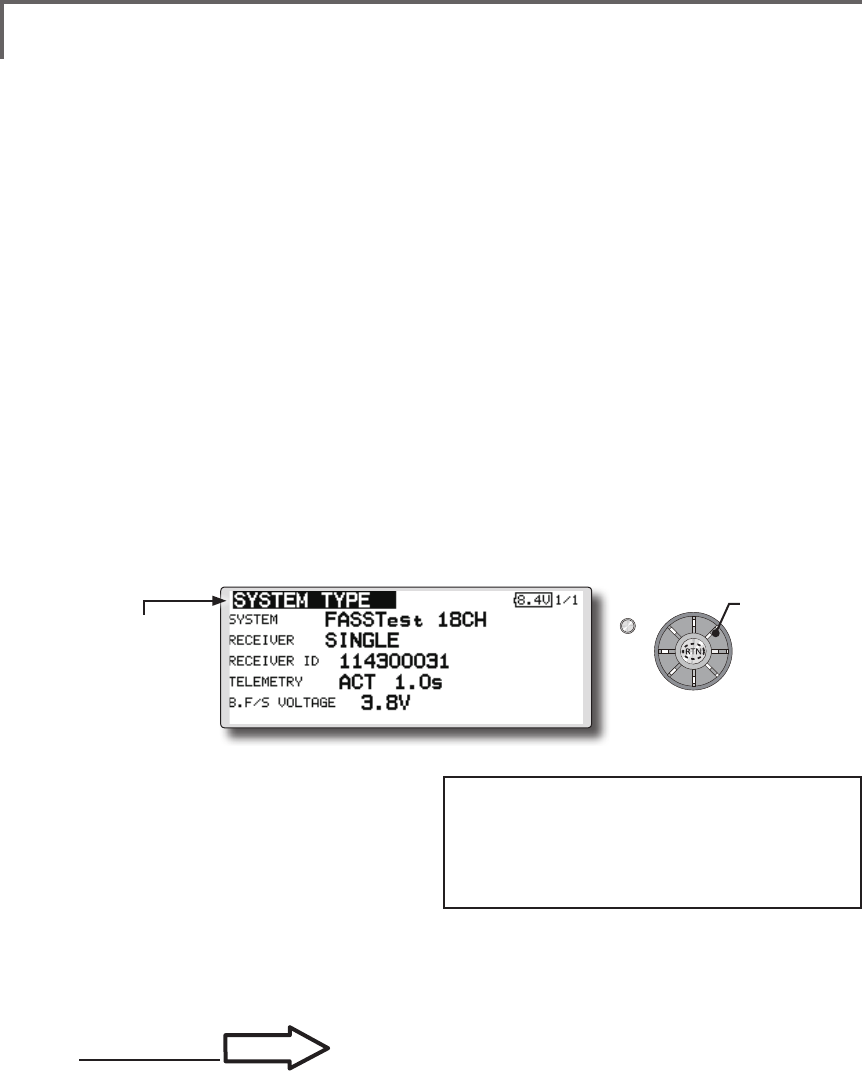
54 <Functions of Linkage Menu>
S1
<Edit dial>
● Select the function name
and return to the Linkage
menu by pushing the RTN
button or pushing the
Home/Exit button.
System Type selection
The FMT-03 is for 2.4GHz only. The system
can be changed from among 2 choices: FASSTest
18CH and FASSTest 12CH which can be chosen by
FMR-03 set.
*If you change the System Type, other model data is not
reset.
*After any change, remember to test the model and should
fully check servo direction and a motion.
*Analog servos cannot be used with the FMR-03 in the
FASSTest 12CH mode.
SYSTEM TYPE System mode setting, Receiver link
Receiver linking
The receiver will only be controlled (without
being affected by other transmitters) by the
transmitter it is linked to. When using a receiver
other than one purchased as a set, linking is
necessary.
Moreover, a re-link is required when a new
model is added by model selection, and the time of
system type change.
Dual receiver function (only FASSTest 18CH
mode)
Dual receivers can be linked with the FMT-03.
Two receivers are recognized individually by ID
numbers. Two sets of receivers can be used as a set
in the model. Separate fail-safe voltage can be set
to each receiver.
However, telemetry cannot be used for the 2nd
receiver.
Battery fail-safe voltage setup (only FASSTest
mode)
The voltage which battery fail-safe activates,
can be set when you link. (3.5-8.4V) The receiver
memorizes the setting as it was at link.
Suggested setting voltages are as follows.
• 4 cells NiCd or NiMH (Normal: 4.8v) = 3.8 v
• 2 cells LiFe (Normal: 6.6 v) = 5.2 ~ 5.4 v
• 2 cells LiPo (Normal: 7.4 v) = 6.6 ~ 6.8 v
It is a rough reference value.
Since it changes with servos carried in the
condition and the model of a battery, please set to
your own model in a battery consumption current.
● Select [SYSTEM] in the Linkage menu and access the
setup screen shown below by pushing the RTN button.
P.33
Linking method
Cases when linking is necessary:
・When using a receiver other than the initial setting.
・When the communication system was changed.
(FASSTest 18CH ↔FASSTest 12CH etc. )
・When a new model was created by model
selection.
Scrolling
● Moving cursor
● Selecting mode
● Adjusting value
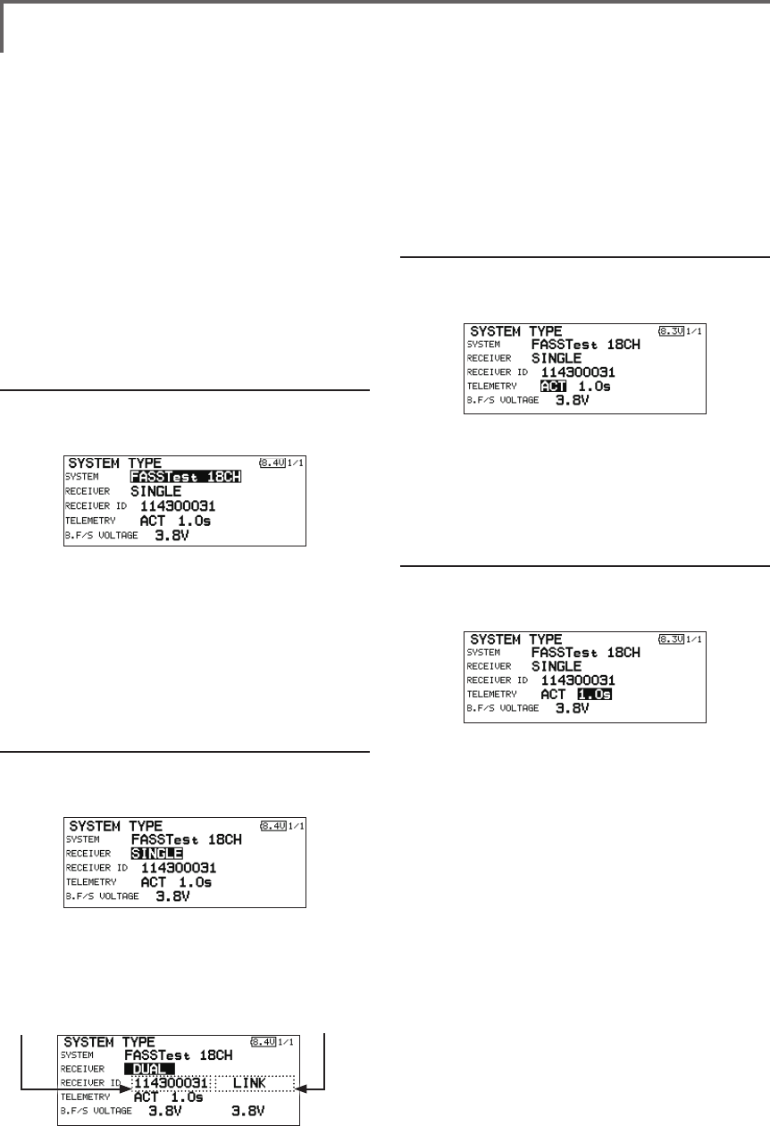
55
<Functions of Linkage Menu>
Telemetry function (FASSTest 18CH mode only)
To use the telemetry function, set “Telemetry” to
“ACT”.
DL Interval (FASSTest 18CH mode only)
When a telemetry function is enabled, the
receiving interval (down-link interval) of sensor
data can be changed.
If a DL interval is increased, the response of
the sensor data display becomes slower, but stick
response will improve.
System Type selection procedure
1. Move the cursor to the [FASSTest-18CH] item
and push the RTN button to switch to the
data input mode.
2. Select the system type by scrolling the edit
dial.
[FASSTest 18CH][FASSTest 12CH]
*An example of selections for each system is on the following
page.
3. Push the RTN button to end adjustment and
return to the cursor mode.
Dual receiver function (only FASSTest 18CH
mode) procedure
1. Move the cursor to the [SINGLE] item and
push the RTN button to switch to the data
input mode.
2. Select the [SINGLE] or [DUAL] by scrolling the
edit dial.
3. Push the RTN button to end adjustment and
return to the cursor mode.
Telemetry ACT/INH procedure
1. Move the cursor to the TELEMETRY [ACT] item
and push the RTN button to switch to the
data input mode.
2. Select the [ACT] or [INH] by scrolling the edit
dial.
3. Push the RTN button to end adjustment and
return to the cursor mode.
DL Interval set procedure
1. Move the cursor to the TELEMETRY DL [1.0s]
item and push the RTN button to switch to
the data input mode.
2. Select the DL time by scrolling the edit dial.
If a DL interval is increased, the response of
the sensor data display becomes slower, but
stick response will improve.
Initial value: 1.0s
Adjustment range : 0.1s~2.0s
3. Push the RTN button to end adjustment and
return to the cursor mode.
In DUAL, a primary receiver is link previously.
Next, a secondary receiver is link.
ID of a Primary
receiver displays.
ID of a Secondary
receiver displays.
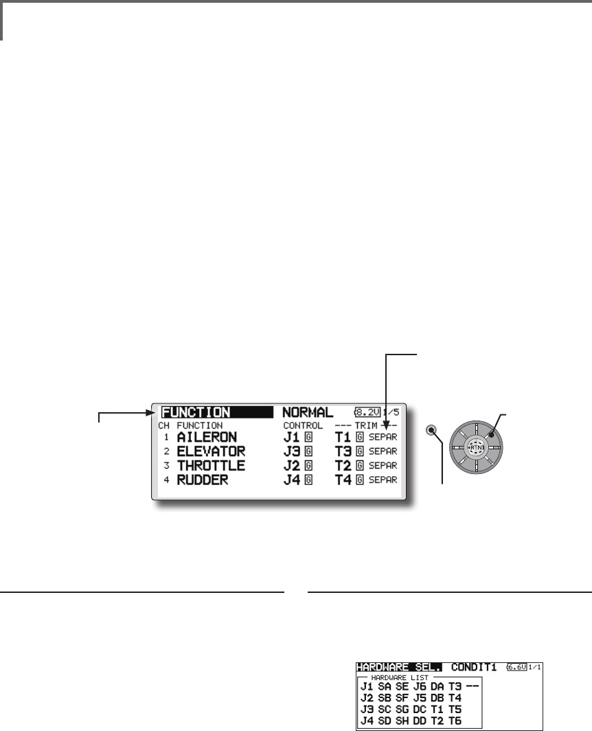
56 <Functions of Linkage Menu>
S1
<Edit dial>
● Select the function name
and return to the Linkage
menu by pushing the RTN
button or pushing the
Home/Exit button.
FUNCTION Channel assignment of each function can be changed.
Function change
1. Use the edit dial to move the cursor to the
"FUNCTION" item of the channel you want to
change and push the RTN button.
*The function selection screen is displayed.
2. Use the edit dial to move the cursor to the
function name you want to set and push the
RTN button.
*The function name blinks.
3. Push the RTN button to execute the change.
(When you want to cancel this operation,
operate the edit dial or S1 button.)
*Multiple channels can be assigned to one function.
Operation control change
1. Use the edit dial to move the cursor to the
"CONTROL" item of the channel you want to
change and push the RTN button.
*The control selection screen is displayed.
2. Use the edit dial to move the cursor to the
control you want to change, and push the
RTN button.
*The same control can be assigned to multiple channels.
*The setting can be changed for each condition.
After the set mode is changed from group mode [G] to
single mode [S] at the control selection screen, only that
condition setting is changed by control change; setting of
other conditions remains the same.
(The display screen is an example. The screen
depends on the model type.)
● Select [FUNCTION] at the linkage menu and call the
setup screen shown below by pushing the RTN button.
● Trim operation mode
"COMB": Combination mode
"SEPAR": Separate mode
When you select model and wing (swash) types,
you will find that the optimized combinations of
servo output channels and functions have been
already preset. If you would like, you can freely
change combinations of servo output channels,
functions (aileron, elevator, etc), and control (sticks,
switches, and trim levers).
*You can also assign the same function to multiple servo
output channels such as assigning elevator function to CH2
and CH3.
Channel Replacement
When the channel is replaced in the function
menu, replaced channel uses the setting data (End
point, SUB-TRIM, REVERSE, F/S, and B-F/S,
etc.).
Servo Output Channels
For FASSTest 12CH mode, you can set 12 linear
channels and two digital channels. For FASSTest
18CH mode, you can set 16 linear channels and
two digital channels.
*DG1/2 (digital channels)
These channels can function as switched channels. You can
freely change combinations between servo output channels
and input controls (sticks, switches, and trim levers).
Motor Function
If you have either a glider or airplane model type
selected, and choose to activate the motor function,
a reverse setting screen is displayed.
*If "YES" is selected, the output is reversed. If "NO" is
selected, the output is normal.
Scrolling
● Moving cursor
● Selecting mode
● Push the S1 button
to call next page.
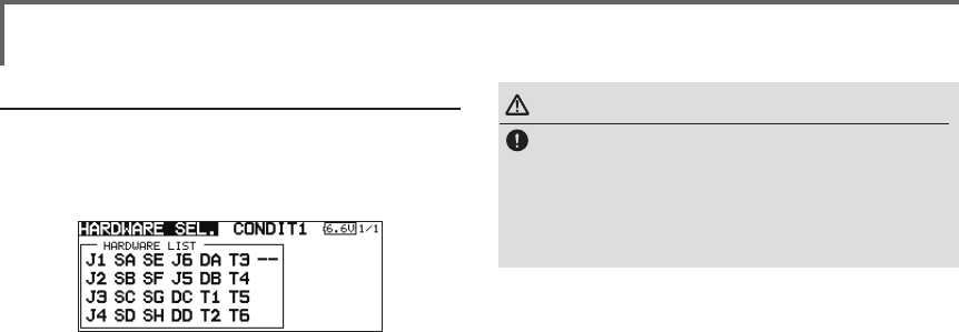
57
<Functions of Linkage Menu>
Trim setting
Use the edit dial to move the cursor to the
"TRIM" item of the channel you want to
change and push the RTN button.
*The trim setup screen is displayed.
The following items can be set at the trim
setup screen:
*The setting can be changed for each condition.
After the set mode is changed from group mode [G] to
single mode [S] at the control selection screen, only that
condition setting is changed by control change; setting of
other conditions remains the same.
Trim selection
Use the edit dial to move the cursor to the
trim, lever, etc. you want to set and push the
RTN button.
*The setting can be changed.
Trim rate setting
Use the edit dial to move the cursor to the
[RATE] item and push the RTN button to
switch to the data input mode.
Set the trim rate by turning the edit dial.
Initial value: +30%
Adjustment range : 0~150%
(When the RTN button is pushed for 1 second, the trim rate is
reset to the initial value.)
Push the RTN button to end adjustment and
return to the cursor move mode.
Trim mode selection
Use the edit dial to move the cursor to the
[TRIM MODE] item and select the trim mode
by turning the edit dial.
[NORM]: Normal mode. Normal trim (parallel
shift trim) operation.
[ATL]: ATL operation mode. Maximum
change near center by operation normally
used with throttle trim. Reverse is also
possible.
[NORM]/[REV] selection is possible at the "ATL
REV" item.
[CENTER]: Maximum change near center by
center trim operation.
WARNING
As a safety precaution to prevent the motor
from starting unexpectedly, please switch
off the motor accordingly. We also suggest
removing the propeller from the motor as an
additional precaution.
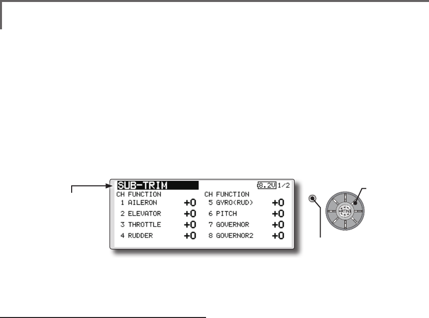
58 <Functions of Linkage Menu>
S1
<Edit dial>
● Select the function name
and return to the Linkage
menu by pushing the RTN
button or pushing the
Home/Exit button.
SUB-TRIM Setting of neutral position of each servo.
(The display screen is an example. The screen
depends on the model type.)
The Sub-Trim function is used to set the servo
neutral position, and may be used to make fine
adjustments to the control surface after linkages
and pushrods are hooked up. When you begin to set
up a model, be sure that the digital trims are set to
their center position.
Sub trim adjustment
1. Use the edit dial to move the cursor to the
channel you want to adjust and push the
RTN button to switch to the data input mode.
2. Adjust by turning the edit dial.
Initial value: 0
Adjustment range: -240~+240 (steps)
(When the RTN button is pushed for 1 second, sub trim is
reset to the initial value.)
*Before sub trim adjustment, adjustment of the linkage so that
control surfaces need not use sub trim as much as possible is
very important.
3. Repeat this procedure for each channel.
● Select [SUB-TRIM] at the linkage menu and call the
setup screen shown below by pushing the RTN button.
Scrolling
● Moving cursor
● Adjusting value
● Push the S1 button
to call next page.
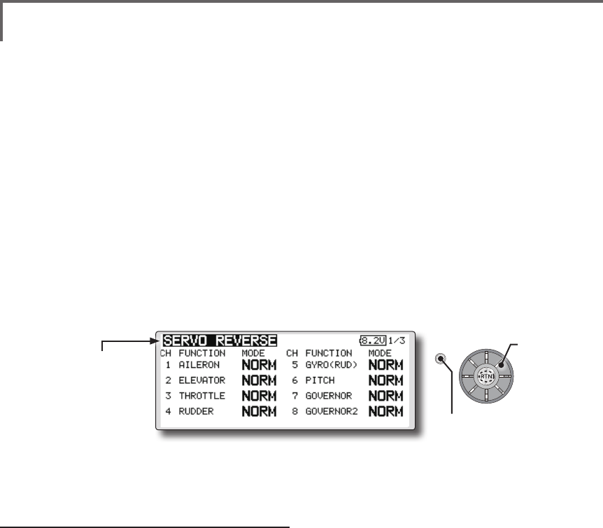
59
<Functions of Linkage Menu>
S1
● Select the function name
and return to the Linkage
menu by pushing the RTN
button or pushing the
Home/Exit button.
<Edit dial>
SERVO-REVERSE Use to reverse the throw direction.
Servo Reverse changes the direction of an
individual servo’s response to a control stick
movement.
For CCPM helicopters, be sure to read the
section on Swash AFR before reversing any servos.
With CCPM helicopters, always complete your
servo reversing prior to any other programming.
If you use pre-built Airplane/Sailplane functions
Servo reversing procedure
*After linkage of a new model is complete, check whether or
not each servo is connected to the correct channel.
*Next, determine whether you need to reverse any channels
by moving each stick.
1. Use the edit dial to move the cursor to the
channel you want to reverse and push the
RTN button to switch to the data input mode.
2. Turn the edit dial and change the display to
[REVERSE] (or [NORMAL]).
*The display blinks.
3. When the RTN button is pushed, servo
operation is reversed. (Operate edit dial or S1
button to stop reversal.)
*Repeat the operation above for each channel that must be
reversed.
that control multiple servos, it may be confusing
to tell whether the servo needs to be reversed or a
setting in the function needs to be reversed. See the
instructions for each specialized function for further
details. Always check servo direction prior to every
ight as an additional precaution to conrm proper
model memory, hook ups, and radio function.
(The display screen is an example. The screen
depends on the model type.)
● Select [SERVO REVERSE] at the linkage menu and call the
setup screen shown below by pushing the RTN button.
Scrolling
● Moving cursor
● Selecting mode
● Push the S1 button
to call next page.
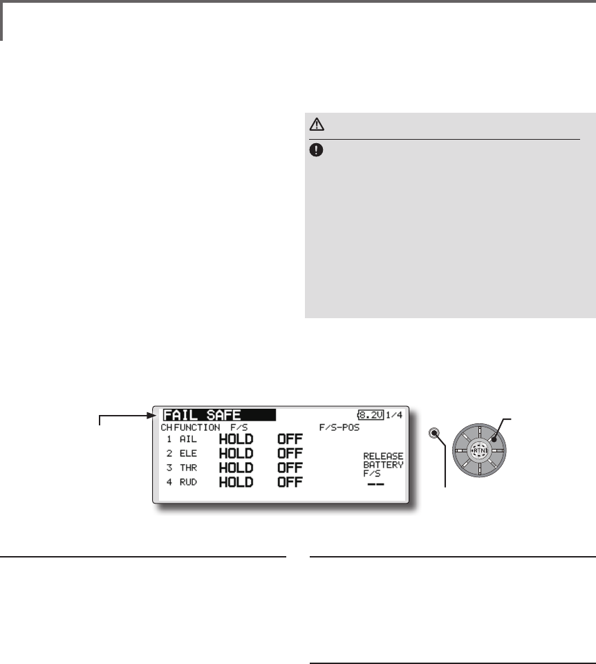
60 <Functions of Linkage Menu>
S1
<Edit dial>
● Select the function name
and return to the Linkage
menu by pushing the RTN
button or pushing the
Home/Exit button.
(The display screen is an example. The screen
depends on the model type.)
● Select [FAIL SAFE] at the linkage menu and call the setup
screen shown below by pushing the RTN button.
FAIL SAFE Sets the servos operating position when transmitter signals can no
longer be received or when the receiver battery voltage drops.
The Failsafe function may be used to set up
positions that the servos move to in the case of
radio interference.
You may set either of two positions for each
channel: Hold, where the servo maintains its last
commanded position, or Failsafe, where each
servo moves to a predetermined position. You may
choose either mode for each channel.
The FMT-03 system also provides you with an
advanced battery monitoring function that warns
you when the receiver battery has only a little
power remaining. In this case, each servo is moved
to the dened failsafe position. The battery failsafe
may be released by operating a predened control
on the transmitter, do not continue to fly, land as
soon as possible. Remember, if the predefined
control suddenly moves to a position you did not
command, land at once and check your receiver
Fail safe setting procedure
1. Move the cursor to the "F/S" item of the
channel you want to set and push the RTN
button to switch to the data input mode.
2. Select the F/S mode by scrolling the edit dial.
A conrmation message appears.
*The display blinks.
3. Push the RTN button. (Push the S1 button to
stop setting.)
*The channel switches to the F/S mode.
4. Move the cursor to the "POS" item.
Hold the corresponding stick, knob, slider,
etc. in the position you want the servo
to move to when the fail safe function is
activated and push the RTN button for one
second.
*The set position is displayed in percentage.
*If you want to return that channel to the hold mode, move
the cursor to the "F/S" item and push the RTN button to
switch to the data input mode. Select the F/S mode by
scrolling the edit dial. A conrmation message appears and
then change the mode by pushing the RTN button.
battery.
Denes servo position when signals are lost and
when receiver battery voltage becomes low.
WARNING
For safety, always set the fail safe functions.
●Remember to set the throttle channel fail safe function
so that the servo moves to the maximum slow side for
airplanes and to the slow side from the hovering position
for helicopters. Crashing of the model at full high when
normal radio waves cannot be received due to interference,
etc., is very dangerous.
●If the battery fail safe is reset by the throttle stick, it may
be mistaken for an engine malfunction and will be reset
at throttle slow and the model will continue to y. If you
have any doubts, immediately land.
Battery fail safe setting procedure
Battery fail safe can be set for each channel
by the same method as the fail safe setting
procedure. Select and set the "B.F/S" item.
[ON]: Battery fail safe function ON
[OFF]: Battery fail safe function OFF
Battery fail safe release switch setting
This function temporarily releases the battery
fail safe function, so the model can recover
after the battery fail safe function was
activated by a drop in the receiver battery
voltage. This setting selects the switch which
releases the battery fail safe function.
1. Move the cursor to the [RELEASE B.F/S] item in
the setup screen (last page).
2. Push the RTN button.
*The switch selection screen is called.
*For a detailed description of the switch selection and ON/
OFF direction setting method, see [Switch Setting Method]
at the back of this manual.
Scrolling
● Moving cursor
● Selecting mode
● Push the S1 button
to call next page.
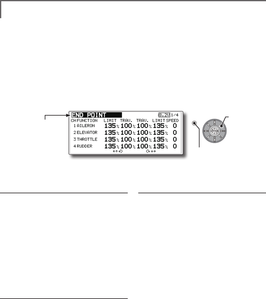
61
<Functions of Linkage Menu>
S1
<Edit dial>
● Select the function name
and return to the Linkage
menu by pushing the RTN
button or pushing the
Home/Exit button.
END POINT Sets the travel, limit point, and speed of each servo.
The End Point function adjusts the left and right
servo throws, generates differential throws, and
will correct improper linkage settings.
The travel rate can be varied from 30% to 140%
in each direction on channels 1 to 12. Also, the
limit point where servo throw stops may be varied
from 0% to 155%.
Servo travel adjustment
1. Use the edit dial to move the cursor to the
"TRAV." item of the channel you want to
adjust and push the RTN button to switch to
the data input mode.
2. Turn the edit dial to adjust the rate.
Initial value: 100%
Adjustment range: 30%~140%
(When the RTN button is pushed for 1 second, the rate is
reset to the initial value.)
Push the RTN button to end adjustment and
return to the cursor move mode.
3. Repeat this procedure for each rate.
Limit point adjustment
1. Use the edit dial to move the cursor to the
"LIMIT" item of the channel you want to adjust
and push the RTN button to switch to the
data input mode.
2. Turn the edit dial to adjust the limit point.
Initial value: 135%
Adjustment range: 0%~155%
(When the RTN button is pushed for 1 second, the limit point
is reset to the initial value.)
Push the RTN button to end adjustment and
return to the cursor move mode.
3. Repeat this procedure for each limit point.
NOTE: The servo speed setting is used to set the servo delay
for each channel, from channel l to channel 12. The system
uses the programmed speed (delay) to slow down servo
position changes. The servo speed setting can be varied from
0 to 27 in each channel.
Servo speed setting
1. Use the edit dial to move the cursor to the
"SPEED" item of the channel you want to
adjust and push the RTN button to switch to
the data input mode.
2. Turn the edit dial to adjust the servo speed.
Initial value: 0
Adjustment range: 0~27 (steps)
(When the RTN button is pushed for 1 second, the servo
speed is reset to the initial value.)
Push the RTN button to end adjustment and
return to the cursor move mode.
3. Repeat this procedure for each channel.
● Select [END POINT] at the linkage menu and call the
setup screen shown below by pushing the RTN button.
(The display screen is an example. The screen
depends on the model type.)
Scrolling
● Moving cursor
● Adjusting value
● Push the S1 button
to call next page.
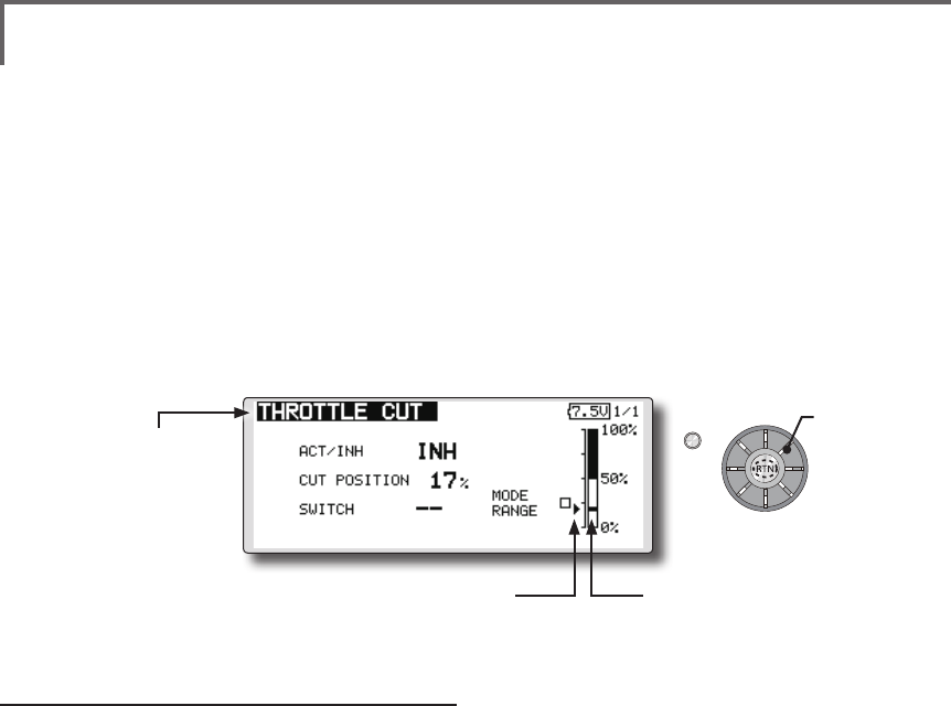
62 <Functions of Linkage Menu>
S1
<Edit dial>
● Select the function name
and return to the Linkage
menu by pushing the RTN
button or pushing the
Home/Exit button.
THROTTLE CUT Stops the engine safely and easily. (Airplane and helicopter only)
Throttle cut provides an easy way to stop the
engine, by ipping a switch with the throttle stick
at idle. The action is not functional at high throttle
to avoid accidental dead sticks. The switch’s
location and direction must be chosen, as it defaults
to NULL.
Throttle cut setting procedure
*Perform the following settings before using the edit dial to
move the cursor to the item to be set.
1. Activate the function:
Move the cursor to the [ACT/INH] item and
push the RTN button to switch to the data
input mode.
Turn the edit dial to the left until the blinking
changes from "INH" to "ACT" and then push
the RTN button.
2. Switch setting:
Move the cursor to the [SWITCH] item and
call the switch setup screen by Pushing the
RTN button and select the switch and ON
direction.
(For a detailed description of the setting method, see
[Switch Setting Method] at the back of this manual.)
3. Throttle cut position setting:
Move the cursor to the [CUT POSITION] item
and push the RTN button to switch to the
data input mode.
Adjust the servo operation position at throttle
cut operation by turning the edit dial to the
left or right.
Initial value: 17%
Adjustment range: 0%~50%
(When the RTN button is Pushed for 1 second, the servo
operation position is reset to the initial value.)
Push the RTN button to end adjustment and
return to the cursor move mode.
*With the selected cut switch ON and the throttle stick at idle;
adjust the rate until the engine consistently cuts off.
However, be sure that the throttle linkage is not pulled too
tight and unreasonable force is not applied to the servo.
● Select [THROTTLE CUT] at the linkage menu and call the
setup screen shown below by pushing the RTN button.
● Current throttle position ● Cut position
Scrolling
● Moving cursor
● Selecting mode
● Adjusting value
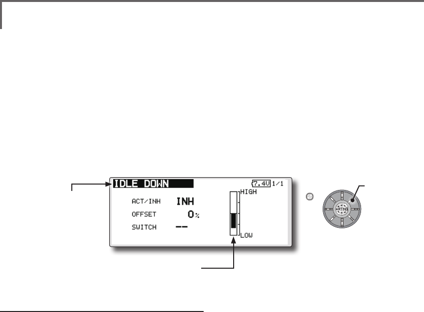
63
<Functions of Linkage Menu>
S1
<Edit dial>
● Select the function name
and return to the Linkage
menu by pushing the RTN
button or pushing the
Home/Exit button.
IDLE DOWN Lowers the engine idling speed. (Airplane and helicopter only)
The Idle Down function lowers the engines idle
by ipping a switch with the throttle stick at idle.
The action is not functional at high throttle to avoid
accidental dead sticks. The switch’s location and
direction must be chosen, as it defaults to NULL.
Idle down setting procedure
*Perform the following settings after using the edit dial to
move the cursor to the item you want to set.
1. Activate the function:
Move the cursor to the [ACT/INH] item and
push the RTN button to switch to the data
input mode.
Switch the blinking from "INH" to "ACT" by
turning the edit dial to the left and then push
the RTN button.
2. Switch setting:
Move the cursor to the [SWITCH] item, call
the switch setup screen by pushing the
RTN button, and select the switch and ON
direction.
(For a detailed description of the setting method, see [Switch
Setting Method] at the back of this manual.)
3. Offset rate setting:
Move the cursor to the [OFFSET] item and
push the RTN button to switch to the data
input mode.
Adjust the servo offset rate at idle down
operation by turning the edit dial to the left
or right.
Initial value: 0%
Adjustment range: -100%~100%
(When the RTN button is pushed for 1 second, the offset rate
is reset to the initial value.)
*Maximum offset amount is near maximum slow.
*When a minus rate is input, offset is applied to the high side.
Push the RTN button to end adjustment and
return to the cursor move mode.
● Select [IDLE DOWN] at the linkage menu and call the setup
screen shown below by pushing the RTN button.
● Current throttle position
Scrolling
● Moving cursor
● Selecting mode
● Adjusting value
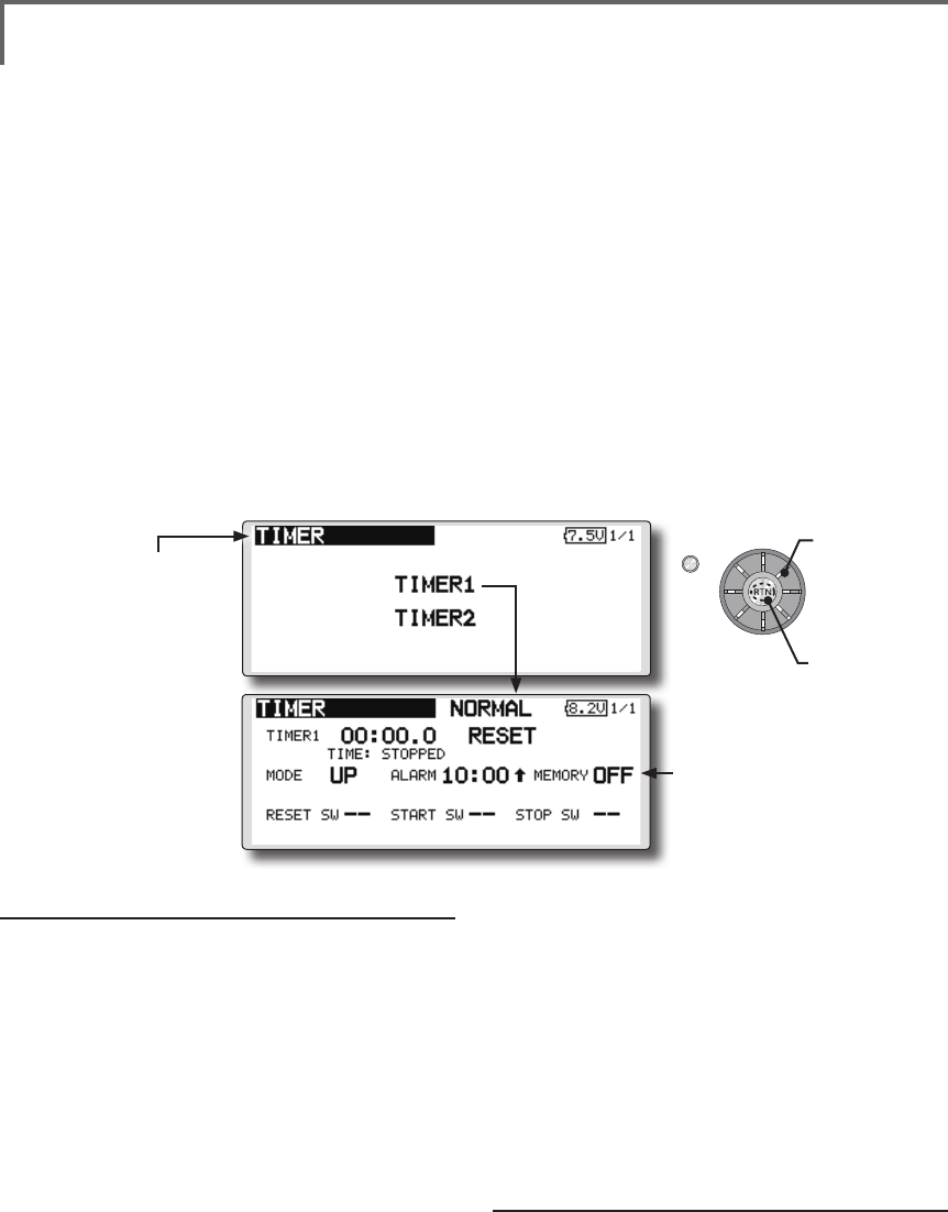
64 <Functions of Linkage Menu>
S1
<Edit dial>
● Select the function name
and return to the Linkage
menu by pushing the RTN
button or pushing the
Home/Exit button.
TIMER Timer setting
The Timer function may be set for any desired
time, i.e. engine run time, specified times for
competitions, etc. Two independent timers are
provided for your use. The timers are stored
independently with each model, meaning that
when you switch between model setups, the timer
associated with the new model is brought up
automatically.
The timers may be set to start and stop from
the motion of any switch or stick. You may set the
ON and OFF directions freely. Each timer has a
capacity of up to 59 minutes 59 seconds.
Timer setting
*Perform the following settings after using the edit dial to
move the cursor to the item you want to set.
1. Up timer/down timer setting
Move the cursor to the [MODE] item and
push the RTN button to switch to the data
input mode.
Select the mode by moving the edit dial to
the left or right and push the RTN button.
[UP]: Up timer
[DOWN]: Down timer
2. Timer time setting
Move the cursor to the [10]:[100] item and
push the RTN button to switch to the data
input mode.
Set the time by turning the edit dial to the left
or right.
[00]:[00]:[min]:[sec]
Push the RTN button to end adjustment and
Each timer may be set for count-down or count
up operation with a target time.
If a target time is set and the timer reaches the set
time, a buzzer sound for each count is generated.
Countdown timers sound one short beep during
the last twenty seconds and two short beeps during
the last ten seconds before reaching the target, then
a long tone at the target time, and continue counting
with displaying a minus (-) sign. Count-up timers
also beep the last twenty and ten seconds, beep the
target time, and keep counting upwards until shut
down.
return to the cursor move mode.
3. Switch setting
Move the cursor to the item of the switch
you want to set, call the switch setup screen
by pushing the RTN button, and select the
switch and ON direction.
[For a detailed description of the setting method, see [Switch
Setting Method] at the back of this manual.]
[RESET SW]: Reset switch
[START SW]: Start switch
[STOP SW]: Stop switch
Timer operation
● Timer 1 and Timer 2 are started/stopped by
pre-selected start/stop switch.
● To reset a timer, operate the pre-selected
reset switch, or move the cursor to the [RESET]
display on the timer screen and push the RTN
button.
● Select [TIMER] at the linkage menu and call the setup
screen shown below by pushing the RTN button.
● The timer value is held even if the
power is turned off or the model is
switched.
Memory →ON
●Calling setup
screen
Scrolling
● Moving cursor
● Selecting mode

65
<Functions of Linkage Menu>
Alarm mode
*A mode which sounds an alarm every minute during the
remaining time up to the timer alarm time.
1. Change the setting by Pushing ↑or
↓button.
[
↑]: An alarm sounds every minute of the
elapsed time from timer start. (Conventional
mode)
[
↓]: An alarm sounds every minute of the
remaining time up to the alarm time.
HOUR mode
*An HOUR mode counts up to 99 hours 50 minutes to the
timer modes.
● This mode is convenient when used at
engine maintenance period and other long
term measurements.
● When the HORU mode is set, "xx(hour) :
xx(minute)" is displayed on the count time
display. Seconds are not displayed.
● When the HORU mode is set, " : " blinks each
second during timer operation.
● When the HORU mode is set, the alarm
function/lap time measurement function are
inhibited.
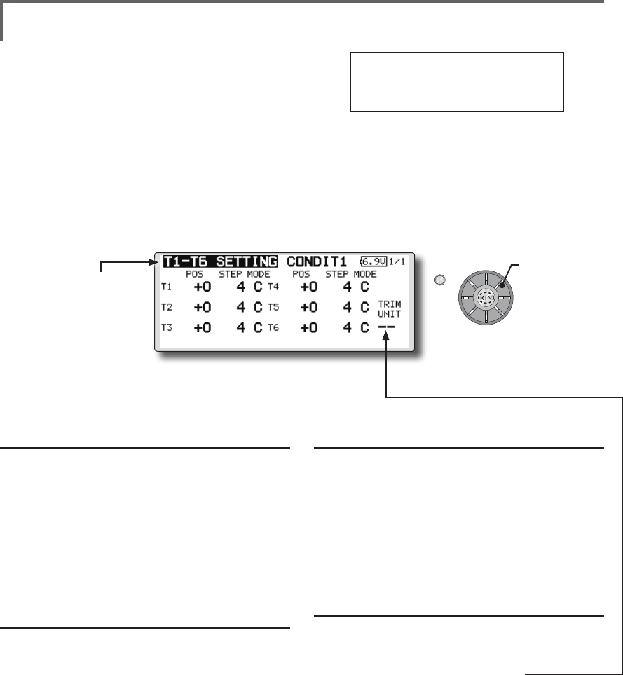
66 <Functions of Linkage Menu>
S1
<Edit dial>
● Select the function name
and return to the Linkage
menu by pushing the RTN
button or pushing the
Home/Exit button.
T1-T6 SETTING Digital trim settings
This function adjusts the digital trim's control
step amount and operation mode (T1-T6).
When the flight conditions are set, the trim
operation can be coupled with among all the
conditions which combination mode is selected.
Trim position setting (neutral offset)
1. Use the edit dial to move the cursor to the
[POS] item and push the RTN button to switch
to the data input mode.
Set the trim position by turning the edit dial.
Initial value: +0 (neutral position)
(When the RTN button is pushed for 1 second, the control
step amount is reset to the initial value.)
2. Push the RTN button to end adjustment and
return to the cursor move mode.
Control step amount setting
1. Use the edit dial to move the cursor to the
[STEP] item and push the RTN button to switch
to the data input mode.
Set the control step amount by turning the
edit dial.
Initial value: 4
Adjustment range: 0(trim off)-200
(When the RTN button is pushed for 1 second, the control
step amount is reset to the initial value.)
*When the value is made large, the change per step becomes
larger.
2. Push the RTN button to end adjustment and
return to the cursor move mode.
C; combination / S; separate mode selection
1. Use the edit dial to move the cursor to the
[C;COMB./S;SEPA.] item and change to
blinking by turning the edit dial and select
the mode by pushing the RTN button.
[C;COMB]: Combination mode. The trim
data are reected at all the ight conditions.
[S;SEPA]: Separate mode. Trim adjustment for
each ight condition.
Trim display units
● Percentage(%) display can be selected at
trim.
1. Select "TRIM UNIT" and turn the dial and
switch the display to [%] or [--].
*The display blinks.
[%]: Trim is displayed in % units.
[--]: Trim is displayed numerically as in the
past.
2. When the RTN button pushed, the setting is
changed.
● Select [T1-T6 SETTING] at the linkage menu and call the setup
screen shown below by pushing the RTN button.
Scrolling
● Moving cursor
● Selecting mode
Trim lever T1-T6 isn't
equipped in FMT-03.
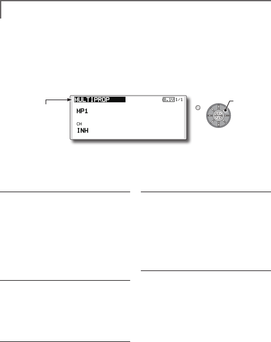
67
<Functions of Linkage Menu>
S1
<Edit dial>
● Select the function name
and return to the Linkage
menu by pushing the RTN
button or pushing the
Home/Exit button.
MULTIPROP CH is extended by MPDX-1 of an option
The system has compatible with the Futaba
MPDX-1 multiprop decoder. One channel can
be expanded to 8 channels by using the MPDX-
1 multiprop decoder. Up to two MPDX-1 can be
used.
*The trim step amount and trim rate are not reset.
Multiprop selection
1. Select the Linkage Menu multiprop setting
[MULTIPROP] and push the RTN button.
2. The MULTIPROP setup screen is displayed.
3. Select [MP1] and push the RTN button.
4. Scrolling the edit dial and switch the display
to [MP1] or [MP2].
*The display blinks.
[MP1]: Multiprop 1
[MP2]: Multiprop 2
5. Push the RTN button.
Channel setting
1. Select [CH] and push the RTN button.
Scrolling the edit dial and display the
channel to which the MPDX-1 is connected.
*To turn off the multiprop function, set [--] at CH.
2. When the activated channel is selected and
push the RTN button, the multiprop setting
contents are displayed.
Control setting
1. Select the "CONTROL" row of the multiprop
channel whose control you want to set and
push the RTN button.
2. A hardware selection screen is displayed.
Select the hardware which is to set control
and push the RTN button.
Servo reverse setting
1. Select the "REVERSE" row of the multiprop
channel which is to be reversed and push
the RTN button.
2. Scrolling the edit dial and switch the display
to [NORM] or [REV].
*The display blinks.
[NORM]: Normal mode
[REV]: Reverse mode
3. Push the RTN button.
End Point Setting
1. Select the " ←↑
" row or " ↓→
" row of the
multiprop channel whose end point is to be
set and switch to the data input mode by
push the RTN button.
2. Adjust the end point by scrolling the edit dial.
Initial value : 100%
Adjustment range : 30-100%
3. After adjustment, push the RTN button.
● Select [MULTPROP] at the linkage menu and call the
setup screen shown below by pushing the RTN button.
Scrolling
● Moving cursor
● Selecting mode
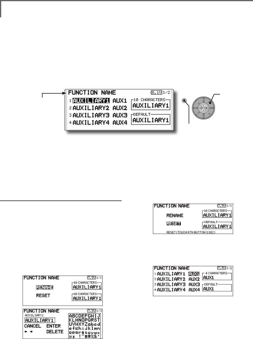
68 <Functions of Linkage Menu>
S1
<Edit dial>
● Select the function name
and return to the Linkage
menu by pushing the RTN
button or pushing the
Home/Exit button.
FUNCTION NAME Function name can be changed
The name of the spare functions
(AUXILIARY1-8) can be changed for the full
name (10 characters) or for the abbreviated name (4
characters).
Function name change method
1. Select [FUNCTION NAME] of the Linkage
Menu and push the RTN button.
2. The FUNCTION NAME setup screen is
displayed.
3. When the function whose name is be
change is selected and the RTN button is
pushed, a modication screen is displayed.
4. Select the function to be renamed and
select [RENAME] and push the RTN button. A
character input screen is displayed. Input the
function name.
5. When [RESET] is selected and the RTN button
is held down, the function name is set to the
initial state function name.
6. The function name may be displayed in 10
characters or 4 characters, depending on
the setup screen. For 4 characters, display,
input the function name as required.
● Select [FUNCTION NAME] at the linkage menu and call the
setup screen shown below by pushing the RTN button.
Scrolling
● Moving cursor
● Push the S1 button
to call next page.
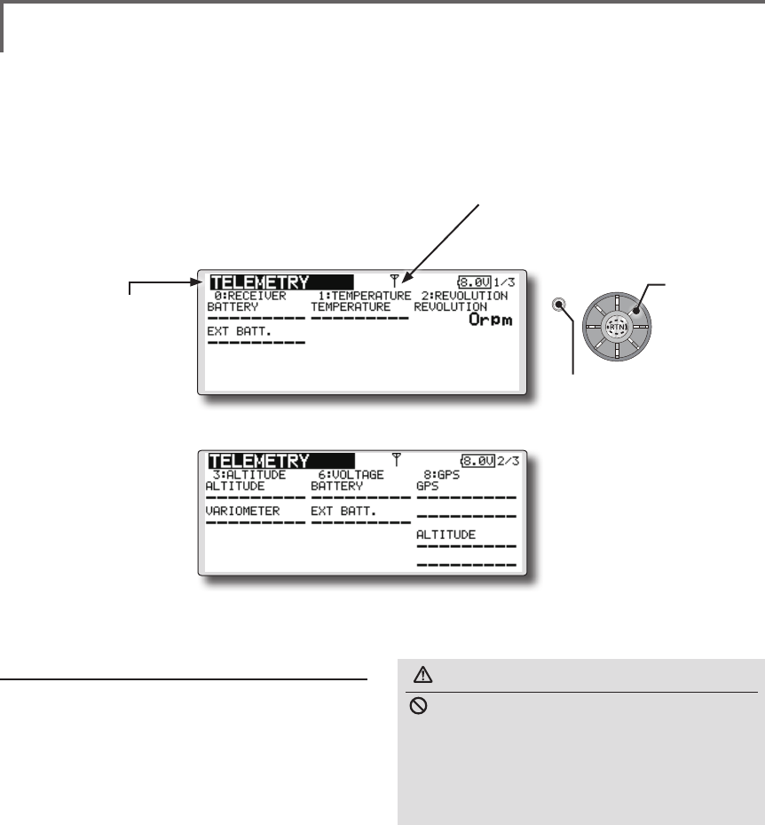
69
<Functions of Linkage Menu>
S1
<Edit dial>
● Select the function name
and return to the Linkage
menu by pushing the RTN
button or pushing the
Home/Exit button.
TELEMETRY Displaying data from the receiver
This screen displays your choice of data from the
receiver.
Also warnings can be activated regarding
other data from your aircraft. For example, if the
receiver voltage drops, the user can be warned by
an alarm (and vibration).
*Only receiver voltage can be used in FASSTest 12CH mode.
*The FASSTest 18CH mode can use all the telemetry
functions.
● Select [TELEMETRY] in the Linkage menu and access the
setup screen shown below by pushing the RTN button.
● Push S1 button to advance to next page.
How to see telemetry data
1. Telemetry screen can be called select
[TELEMETRY] in the Linkage menu and access
the setup screen by pushing the RTN button.
2. If each item is chosen and the RTN button is
pushed, an alarm setup can be performed
with the minimum/maximum after a
transmitter is turned on.
*Receiver voltage can be checked immediately. An optional
sensor will need to be attached to S.BUS2 of a receiver if
you would like to see other information.
*No special setup is necessary if each sensor displayed
is left as in the default setup. Separate sensor ID
is also unnecessary. However, if two or more of
one kind of sensor is used, setup is required in the
"SENSOR" menu.
WARNING
Do not watch the transmitter screen during
ight.
*You may loose sight of the aircraft during ight and this
is extremely dangerous. Have an assistant on hand to
check the screen for you. A pilot should NEVER take
his eyes off his aircraft.
Scrolling
● Moving cursor
● Receiver → Transmitter. The reception
strength is shown.
● Push the S1 button
to call next page.
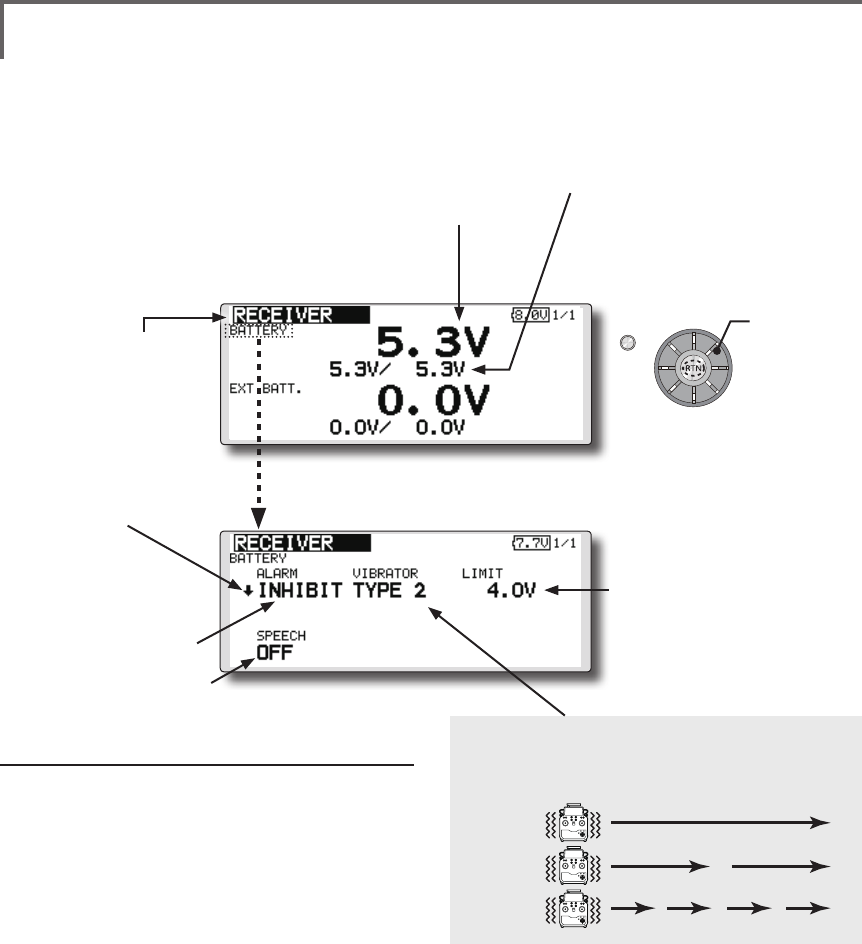
70 <Functions of Linkage Menu>
S1
<Edit dial>
● Select the function name
and return to the Linkage
menu by pushing the RTN
button or pushing the
Home/Exit button.
TELEMETRY : RECEIVER [BATTERY] Displaying data from the
receiver battery voltage
In this screen, the battery voltage of a receiver is
displayed.
If it becomes higher or lower than the setting an
alarm and/or vibration will alert you.
*Only receiver voltage can be used in FASSTest 12CH mode.
*The FASSTest 18CH mode can use all the telemetry
functions.
● Select [Rx-BATT.] in the TELEMETRY screen
and access the setup screen shown below
by pushing the RTN button.
● Select [BATTERY] in the RECEIVER screen
and access the setup screen shown
below by pushing the RTN button.
●A setup of the voltage on
which the alarm operates.
Scrolling
● Moving cursor
● Receiver battery voltage
● The maximum and the minimum when
powering ON are shown. It will be preset,
if a cursor is moved to this place and the
RTN button is pushed for 1 second.
● ↓The "down" arrow will
indicate that an alarm will
sound when the voltage
drops to below the setting.
● ALARM is chosen from
BUZZER, VOICE, and
INHIBIT.
● The ON/OFF switch of SPEECH is chosen.
Alarm set
1. Move the cursor to the ↓ALARM item, and
it chooses from BUZZER, VOICE, INHIBIT, and
pushes RTN.
2. When not operating vibrator, it is "VIBRATOR"
to INHIBIT. TYPE1-3 will be chosen if it is made
to operate.
3. Move the cursor to the LIMIT [4.0V] item and
push the RTN button to switch to the data
input mode.
4. Ajust the rate by scrolling the edit dial.
Initial value: 4.0V
Adjustment range: 0.0V~100.0V
*When the RTN button is pushed for one second, the rate is
reset to the initial value.
5. Push the RTN button. (To terminate the input
and return to the original state, push the
Home/Exit button.)
TYPE 1
TYPE 2
TYPE 3
"VIBRATOR" type
If the following types are selected, the transmitter
will vibrate during the warning.
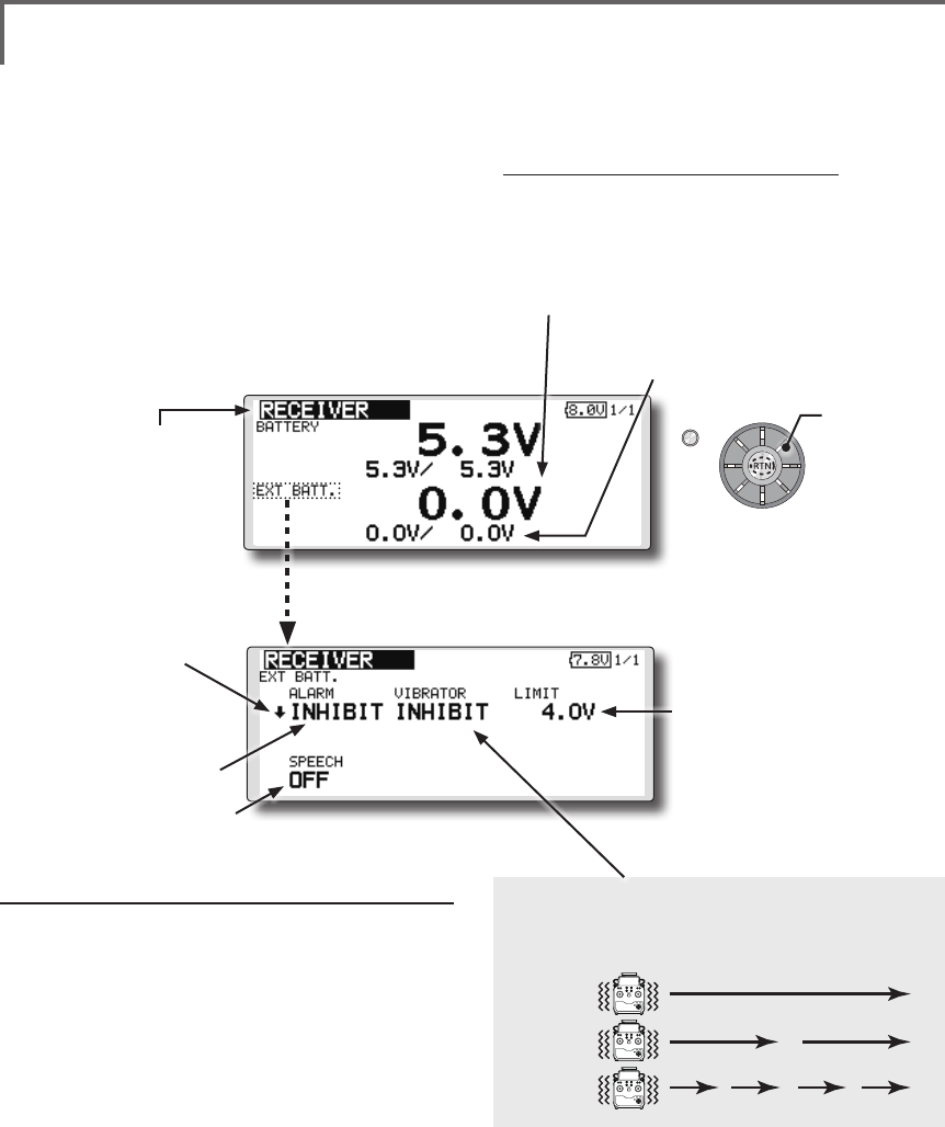
71
<Functions of Linkage Menu>
S1
<Edit dial>
● Select the function name
and return to the Linkage
menu by pushing the RTN
button or pushing the
Home/Exit button.
● Select [Rx-BATT.] in the TELEMETRY screen and
access the setup screen shown below by
pushing the RTN button.
Alarm set
1. Move the cursor to the ↓ALARM item, and
it chooses from BUZZER, VOICE, and INHIBIT,
and pushes RTN.
2. When not operating vibrator, it is "VIBRATOR"
to INHIBIT. TYPE1-3 will be chosen if it is made
to operate.
3. Move the cursor to the LIMIT [4.0V] item and
push the RTN button to switch to the data
input mode.
4. Ajust the rate by scrolling the edit dial.
Initial value: 4.0V
Adjustment range: 0.0V~100.0V
*When the RTN button is pushed for one second, the rate is
reset to the initial value.
5. Push the RTN button. (To terminate the input
and return to the original state, push the
Home/Exit button.)
TYPE 1
TYPE 2
TYPE 3
"VIBRATOR" type
If the following types are selected, the transmitter
will vibrate during the warning.
TELEMETRY : RECEIVER [EXT BATT.] Displaying data from the EXT
battery voltage port
The EXT-VOLT screen will display the data from
the EXT-battery output from the R7008SB receiver.
In order to use this function, it is necessary to
connect external voltage connector of the R7008SB
receiver to a CA-RVIN-700 or SBS-01V to the
battery you desire to measure the voltage of the
EXT-battery.
You will be alerted by an alarm or vibration if
the voltage set by you is exceeded.
*FMR-03 isn't equipped with EXT-battery port.
*Only receiver voltage will be received in the FASSTest 12CH
mode.
*The FASSTest 18CH mode will display all telemetry data.
*CA-RVIN-700 must be installed in the aircraft.
● Select [EXT BATT.] in the RECEIVER screen
and access the setup screen shown
below by pushing the RTN button.
●A setup of the voltage on
which the alarm operates.
Scrolling
● Moving cursor
● EXT battery voltage ● The maximum and the minimum
when powering ON are shown. It will
be preset, if a cursor is moved to this
place and the RTN button is pushed
for 1 second.
● ↓The "down" arrow will
indicate that an alarm will
sound when the voltage
drops to below the setting.
● ALARM is chosen from
BUZZER, VOICE, and
INHIBIT.
● The ON/OFF switch of SPEECH is chosen.
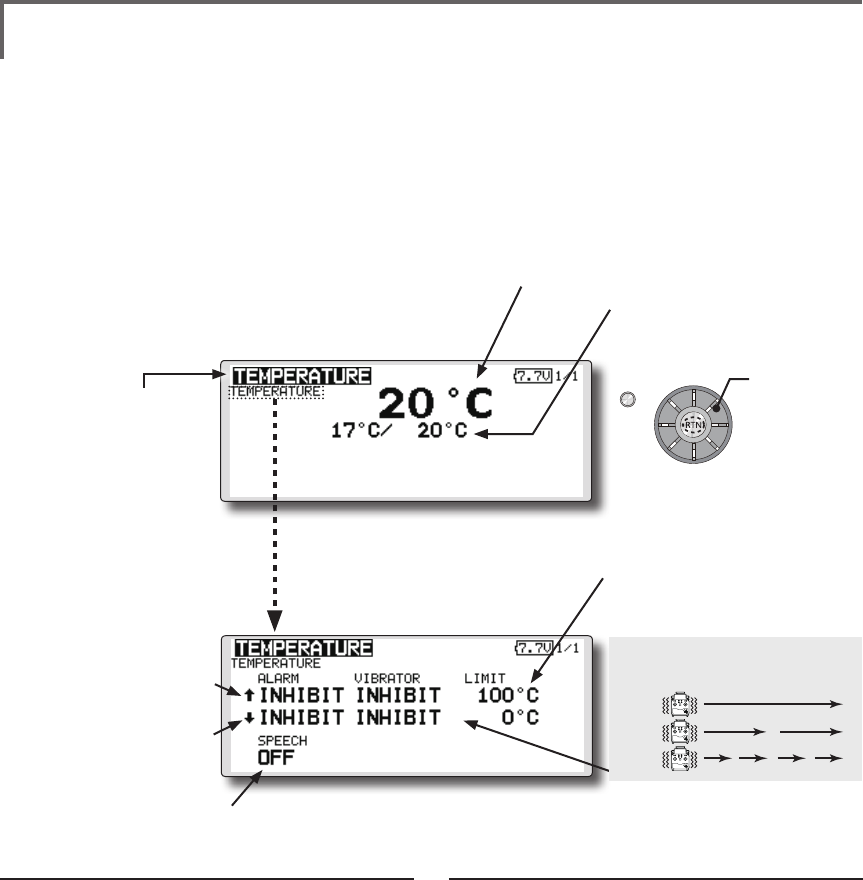
72 <Functions of Linkage Menu>
S1
<Edit dial>
● Select the function name
and return to the Linkage
menu by pushing the RTN
button or pushing the
Home/Exit button.
TELEMETRY : TEMPERATURE Displaying data from the temperature
Temperature is a screen which displays/sets
up the temperature information from an optional
temperature sensor.
The temperature of the model (engine, motor,
battery, etc.) which is ying can be displayed.
If it becomes higher or lower than the setting an
alarm and/or vibration will alert you.
*Only receiver voltage can be used in FASSTest 12CH mode.
*The FASSTest 18CH mode can use all the telemetry
functions.
● Select [TEMPERATURE] in the TELEMETRY screen and access
the setup screen shown below by pushing the RTN button.
Scrolling
● Moving cursor
● Temperature
● The maximum and the minimum when
powering ON are shown. It will be preset,
if a cursor is moved to this place and the
RTN button is pushed for 1 second.
● ↓ A downward arrow
will show that an alarm
will sound when the
temperature drops below
the set value.
● ↑ An upward arrow will show
that an alarm will sound
when the temperature rises
above the set value.
Alert set : Hot warning
1. Move the cursor to the ↑ALARM item, and
it chooses from BUZZER, VOICE, INHIBIT, and
pushes RTN.
2. When not operating vibrator, it is "VIBRATOR"
to INHIBIT. TYPE1-3 will be chosen if it is made
to operate.
3. Move the cursor to the LIMIT [ ℃] item and
push the RTN button to switch to the data
input mode.
4. Ajust the rate by scrolling the edit dial.
Initial value: 100℃
Adjustment range: 0℃~200℃
(↑LIMIT ≧ ↓LIMIT)
*When the RTN button is pushed for one second, the rate is
reset to the initial value.
5. Push the RTN button. (To terminate the input
and return to the original state, push the
Home/Exit button.)
Alert set : Low-temperature warning
1. Move the cursor to the ↓ALARM item, and
it chooses from BUZZER, VOICE, INHIBIT, and
pushes RTN.
2. When not operating vibrator, it is "VIBRATOR"
to INHIBIT. TYPE1-3 will be chosen if it is made
to operate.
3. Move the cursor to the LIMIT [ ℃] item and
push the RTN button to switch to the data
input mode.
4. Ajust the rate by scrolling the edit dial.
Initial value: 0℃
Adjustment range: 0℃~200℃
(↑LIMIT ≧ ↓LIMIT)
*When the RTN button is pushed for one second, the rate is
reset to the initial value.
5. Push the RTN button. (To terminate the input
and return to the original state, push the
Home/Exit button.)
*A temperature sensor must be installed in the aircraft.
●Select [TEMPERATURE](small font
display) in the TEMPERATURE screen
and access the setup screen shown
below by pushing the RTN button.
● The ON/OFF switch of SPEECH is chosen.
●A setup of the temperature on
which the alarm operates.
TYPE 1
TYPE 2
TYPE 3
"VIBRATOR" type
If the following types are selected, the transmitter
will vibrate during the warning.
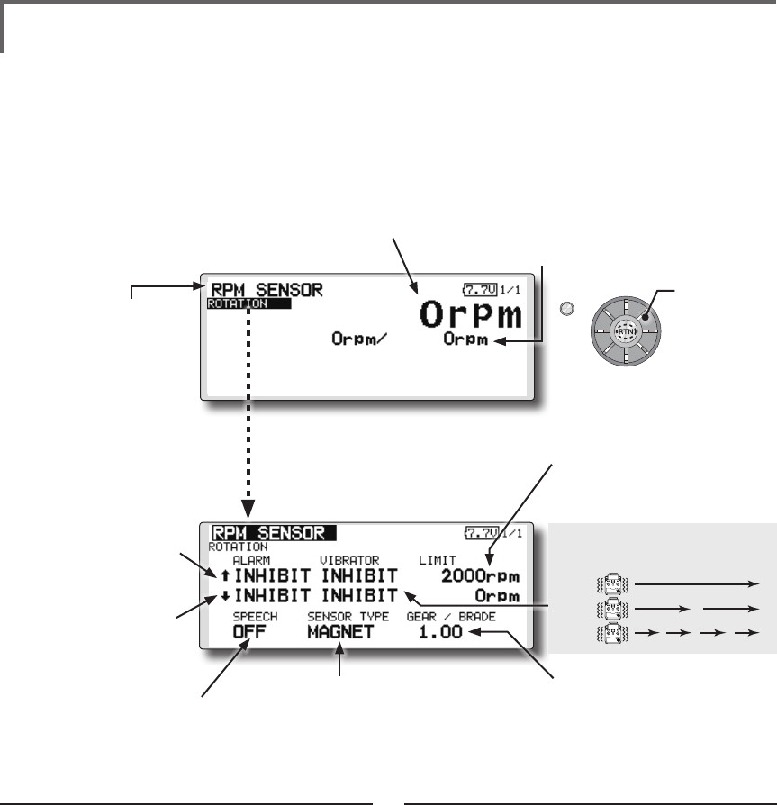
73
<Functions of Linkage Menu>
S1
<Edit dial>
● Select the function name
and return to the Linkage
menu by pushing the RTN
button or pushing the
Home/Exit button.
TELEMETRY : RPM SENSOR Displaying data from the RPM
RPM sensor is a screen which displays / sets up
the rotation information from an optional RPM
sensor.
The rotation of the model (engine, motor, etc.)
which is ying can be shown.
If it becomes higher or lower than the setting an
alarm and/or vibration will alert you.
*Only receiver voltage can be used in FASSTest 12CH mode.
*The FASSTest 18CH mode can use all the telemetry
functions.
Alarm set : Over rotations
1. Move the cursor to the ↑ALARM item, and
it chooses from BUZZER, VOICE, INHIBIT, and
pushes RTN.
2. When not operating vibrator, it is "VIBRATOR"
to INHIBIT. TYPE1-3 will be chosen if it is made
to operate.
3. Move the cursor to the LIMIT [2,000rpm] item
and push the RTN button to switch to the
data input mode.
4. Ajust the rate by scrolling the edit dial.
Initial value: 2,000rpm
Adjustment range: 0rpm~150,000rpm
(↑LIMIT ≧ ↓LIMIT)
*When the RTN button is pushed for one second, the rate is
reset to the initial value.
5. Push the RTN button. (To terminate the input
and return to the original state, push the
Home/Exit button.)
Alarm set : Under rotations
1. Move the cursor to the ↓ALARM item, and
it chooses from BUZZER, VOICE, INHIBIT, and
pushes RTN.
2. When not operating vibrator, it is "VIBRATOR"
to INHIBIT. TYPE1-3 will be chosen if it is made
to operate.
3. Move the cursor to the LIMIT [0rpm] item and
push the RTN button to switch to the data
input mode.
4. Ajust the rate by scrolling the edit dial.
Initial value: 0rpm
Adjustment range: 0rpm~150,000rpm
(↑LIMIT ≧ ↓LIMIT)
*When the RTN button is pushed for one second, the rate is
reset to the initial value.
5. Push the RTN button. (To terminate the input
and return to the original state, push the
Home/Exit button.)
*A RPM sensor must be installed in the aircraft.
● The maximum and the minimum when
powering ON are shown. It will be preset,
if a cursor is moved to this place and the
RTN button is pushed for 1 second.
●A setup of the revolution on
which the alarm operates.
● Select [RPM sensor] in the TELEMETRY screen
and access the setup screen shown below
by pushing the RTN button.
Scrolling
● Moving cursor
● RPM
●"MAGNET" or "OPTICS" is set
according to the sensor
you use.
SBS-01RM : MAGNET
SBS-01RO : OPTICS
● ↓A downward arrow
indicates that the alarm
will sound when the RPM
falls below the set value.
● ↑An upward arrow
indicates that the alarm
will sound when the RPM
rises above the set value.
● In "MAGNET", the gear ratio of your
engine (motor) you are using is
entered.
● In "OPTICS", the number of blades
of the propeller ( r o t o r ) your
model is entered.
●Select [ROTATION](small font display)
in the RPM sensor screen and
access the setup screen shown
below by pushing the RTN button.
● The ON/OFF switch of
SPEECH is chosen.
TYPE 1
TYPE 2
TYPE 3
"VIBRATOR" type
If the following types are selected, the transmitter
will vibrate during the warning.
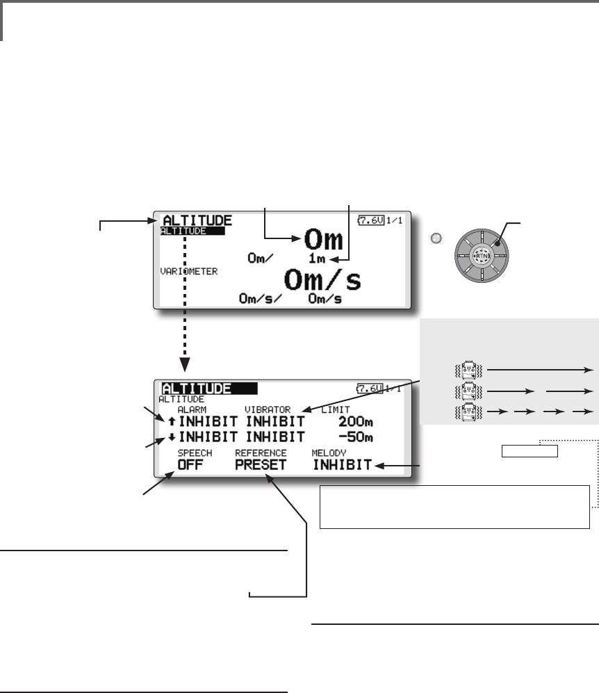
74 <Functions of Linkage Menu>
S1
<Edit dial>
● Select the function name
and return to the Linkage
menu by pushing the RTN
button or pushing the
Home/Exit button.
TELEMETRY : ALTITUDE Displaying data from the altitude
ALTITUDE is a screen which displays / sets up the
altitude information from an optional altitude sensor or GPS
sensor. The altitude of the model which is flying can be
known. If it becomes higher (low) than preset altitude, you
can be told by alarm. To show warning by vibration can also
be chosen. Data when a power supply is turned on shall be
0 m, and it displays the altitude which changed from there.
Even if the altitude of an aireld is high, that shall be 0 m
and the altitude difference from an airfield is displayed.
This sensor calculates the altitude from atmospheric
Pushure. Atmospheric Pushure will get lower as you go up
in altitude, using this the sensor will estimate the altitude.
Please understand that an exact advanced display cannot
be performed if atmospheric Pushure changes in a weather
situation.
*Only receiver voltage can be used in FASSTest 12CH mode.
*The FASSTest 18CH mode can use all the telemetry functions.
● Select [ALTITUDE] in the TELEMETRY screen and
access the setup screen shown below by
pushing the RTN button.
Scrolling
● Moving cursor
● Altitude
● ↓ A downward arrow
indicates the alarm will
sound when the altitude
reaches below your set
value.
● ↑ An upward arrow
indicates the alarm will
sound when the altitude
reaches above your set
value.
First, the set of a reference is required.
1. The model and transmitter to which the
altitude sensor was connected are turned on.
2. Move the cursor to the [PRESET] of
"REFERENCE" item.
3. Push the RTN button is pushed for 1 second.
(To terminate the input and return to the original
state, push the Home/Exit button.)
*Atmospheric Pushure is changed according to the weather also
at the same aireld. You should preset before a ight.
Alarm set : High side
1. Move the cursor to the ↑ALARM item, and
it chooses from BUZZER, VOICE, INHIBIT, and
pushes RTN.
2. When not operating vibrator, it is "VIBRATOR"
to INHIBIT. TYPE1-3 will be chosen if it is made
to operate.
3. Move the cursor to the LIMIT [m] item and
push the RTN button to switch to the data
input mode.
4. Ajust the rate by scrolling the edit dial.
Initial value: 200m
Adjustment range-500m~+3,000m
(↑LIMIT ≧ ↓LIMIT)
*When the RTN button is pushed for one second, the rate is
reset to the initial value.
5. Push the RTN button. (To terminate the input
and return to the original state, push the
Home/Exit button.)
Alarm set : Low side
1. Move the cursor to the ↓ALARM item, and
it chooses from BUZZER, VOICE, INHIBIT, and
pushes RTN.
2. When not operating vibrator, it is "VIBRATOR"
to INHIBIT. TYPE1-3 will be chosen if it is made
to operate.
3. Move the cursor to the LIMIT [m] item and
push the RTN button to switch to the data
input mode.
4. Ajust the rate by scrolling the edit dial.
Initial value: -50m
Adjustment range-500m~+3,000m
(↑LIMIT ≧ ↓LIMIT)
*When the RTN button is pushed for one second, the rate is
reset to the initial value.
5. Push the RTN button. (To terminate the input
and return to the original state, push the
Home/Exit button.)
*An altitude sensor or GPS sensor must be installed in the aircraft.
●Select [ALTITUDE](small font display) in the
TEMPERATURE screen and access the setup
screen shown below by pushing the RTN
button.
● The maximum and the minimum when powering ON are
shown. It will be preset, if a cursor is moved to this place and
the RTN button is pushed for 1 second.
●The ON/OFF switch of SPEECH
is chosen.
●If this is set to MODE1-4, a rise
and dive are told by a different
melody.
MODE1: Little rise/dive→Melody changes (sensitively)
MODE4: Big rise/dive→Melody changes (insensible)
. . .
TYPE 1
TYPE 2
TYPE 3
"VIBRATOR" type
If the following types are selected, the
transmitter will vibrate during the warning.
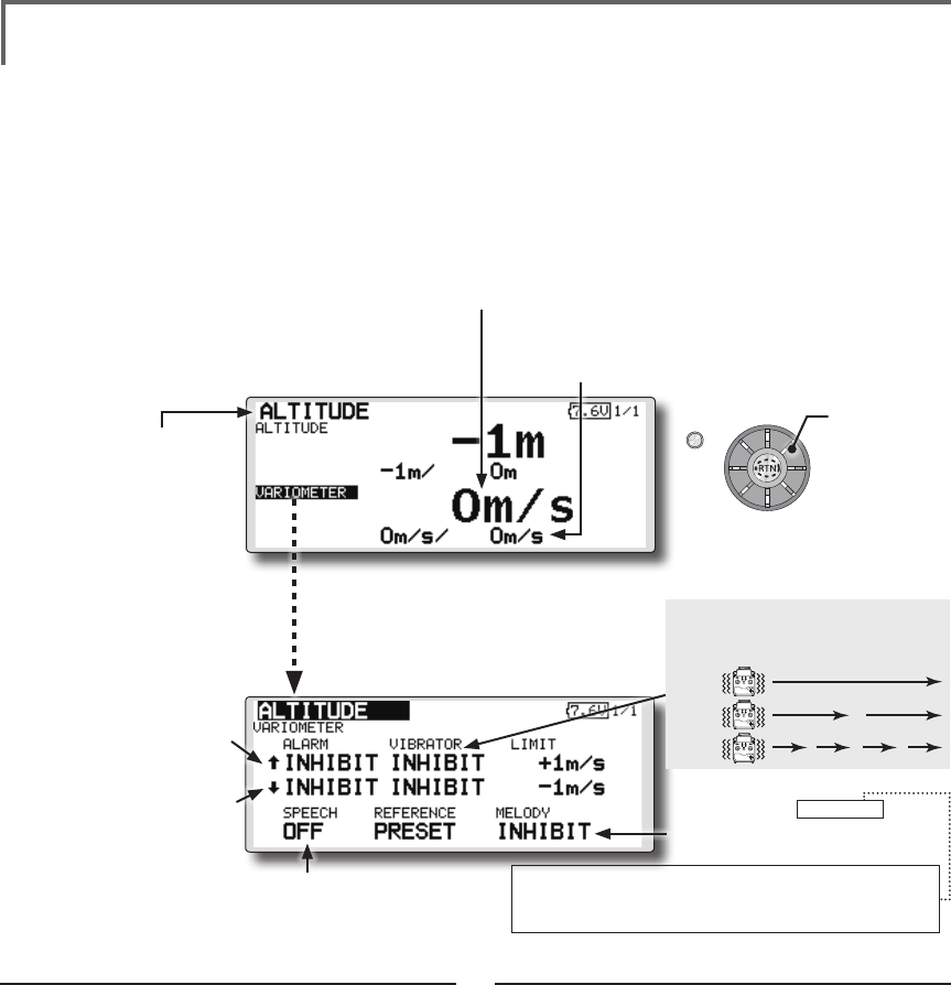
75
<Functions of Linkage Menu>
S1
<Edit dial>
● Select the function name
and return to the Linkage
menu by pushing the RTN
button or pushing the
Home/Exit button.
● Select [ALTITUDE] in the TELEMETRY screen and
access the setup screen shown below by
pushing the RTN button.
TELEMETRY : ALTITUDE [VARIOMETER] Displaying data from the
variometer
VARIO is a screen which displays / sets up the
variometer information from an optional altitude
sensor or GPS sensor.
The variometer of the model which is ying can
be known.
If it becomes higher or lower than the setting an
alarm and/or vibration will alert you.
To ensure that the pilot is aware as to the model's
status, the FMT-03 incorporates a different melody
for ascent and descent. Additionally, depending
upon the rate of climb or descent, the tones vary to
indicate whether or not the airplane is climbing or
descending at a rapid rate.
*Only receiver voltage can be used in FASSTest 12CH mode.
*The FASSTest 18CH mode can use all the telemetry
functions.
Alert set : Rise side
1. Move the cursor to the ↑ALARM item, and
it chooses from BUZZER, VOICE, INHIBIT, and
pushes RTN.
2. When not operating vibrator, it is "VIBRATOR"
to INHIBIT. TYPE1-3 will be chosen if it is made
to operate.
3. Move the cursor to the LIMIT [m/s] item and
push the RTN button to switch to the data
input mode.
4. Ajust the rate by scrolling the edit dial.
Initial value: +1m
Adjustment range -50m/s~+50m/s
(↑LIMIT ≧ ↓LIMIT)
*When the RTN button is pushed for one second, the rate is
reset to the initial value.
5. Push the RTN button. (To terminate the input
and return to the original state, push the
Home/Exit button.)
Alert set : Dive side
1. Move the cursor to the ↓ALARM item, and
it chooses from BUZZER, VOICE, INHIBIT, and
pushes RTN.
2. When not operating vibrator, it is "VIBRATOR"
to INHIBIT. TYPE1-3 will be chosen if it is made
to operate.
3. Move the cursor to the LIMIT [m/s] item and
push the RTN button to switch to the data
input mode.
4. Ajust the rate by scrolling the edit dial.
Initial value: -1m
Adjustment range -50m/s~+50m/s
(↑LIMIT ≧ ↓LIMIT)
*When the RTN button is pushed for one second, the rate is
reset to the initial value.
5. Push the RTN button. (To terminate the input
and return to the original state, push the
Home/Exit button.)
*An altitude sensor or GPS sensor must be installed in the aircraft.
●If this is set to MODE1-4, a rise
and dive are told by a different
melody.
MODE1: Little rise/dive→Melody changes (sensitively)
MODE4: Big rise/dive→Melody changes (insensible)
. . .
Scrolling
● Moving cursor
● ↓ A downward arrow
indicates the alarm will
sound when the variomete
reaches below your set
value.
● ↑ An upward arrow indicates
the alarm will sound when
the variometer reaches
above your set value.
TYPE 1
TYPE 2
TYPE 3
"VIBRATOR" type
If the following types are selected, the
transmitter will vibrate during the warning.
●Select [VARIOMETER](small font
display) in the TEMPERATURE screen
and access the setup screen shown
below by pushing the RTN button.
● The maximum and the minimum when powering ON
are shown. It will be preset, if a cursor is moved to this
place and the RTN button is pushed for 1 second.
● Variometer
●The ON/OFF switch of
SPEECH is chosen.
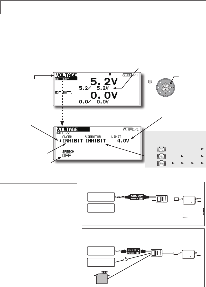
76 <Functions of Linkage Menu>
S1
<Edit dial>
● Select the function name
and return to the Linkage
menu by pushing the RTN
button or pushing the
Home/Exit button.
In this screen, the battery voltage is displayed.
In order to use this function, it is necessary to
connect External voltage connector of FMR-03 ⇔
SBS-01V ⇔ Battery
SBS-01V measures two batteries. The power
battery connected to two lines is displayed on EXT-
VOLT. The battery for receivers connected to 3P
lines is displayed here.
*Only receiver voltage can be used in FASSTest 12CH mode.
*The FASSTest 18CH mode can use all the telemetry
functions.
*SBS-01V must be installed in the aircraft.
<Two examples of wiring are shown >
*Refer to the manual of SBS-01V for the details of wiring.
Drive battery
(EXT Battery)
Switch
Power supplies
for servos
Another
power
supply Hub
S.BUS2
servos
Drive battery are measured (SBS-01V use)
Drive battery and power supplies for servos are measured (SBS-01V use)
●Battery voltage measurement for receivers [FMR-03 use]
●Battery voltage measurement for receivers [SBS-01V use]
●The drive battery is measured in an EXT line [SBS-01V use]
●Battery voltage measurement for receivers [FMR-01 use]
●The drive battery is measured in an EXT line [SBS-01V use]
●The voltage for servos is measured in a power supply line [SBS-01V use]
Normal Line
EXT Line
EXT Line
*SBS-01V measures two voltage. One corresponds to high voltages, such as a drive battery,
with an EXT line. Another is a normal line and is measurement of the battery for receivers of a
line connected to 3P connector, or the battery for servos.
*The same
receiver battery
Receiver battery
Drive battery
(EXT Battery)
TELEMETRY : VOLTAGE [BATTERY] Displaying data from the battery
voltage
●Select [VOLTAGE] in the TELEMETRY screen and access the
setup screen shown below by pushing the RTN button.
●Select [BATTERY] in the VOLTAGE screen and
access the setup screen shown below by
pushing the RTN button.
●A setup of the voltage
on which the alarm
operates.
Scrolling
● Moving cursor
●Battery
voltage
●The maximum and the minimum when
powering ON are shown. It will be preset, if
a cursor is moved to this place and the RTN
button is pushed for 1 second.
●↓The "down" arrow will indicate
that an alarm will sound when
the voltage drops to below the
setting.
●ALARM is chosen from
BUZZER, VOICE, and
INHIBIT.
●The ON/OFF switch of SPEECH is chosen.
Alarm set
1. Move the cursor to the ↓ALARM
item, and it chooses from BUZZER,
VOICE, INHIBIT, and pushes RTN.
2. When not operating vibrator, it is
"VIBRATOR" to INHIBIT. TYPE1-3 will
be chosen if it is made to operate.
3. Move the cursor to the LIMIT [4.0V]
item and push the RTN button to
switch to the data input mode.
4. Ajust the rate by scrolling the edit
dial.
Initial value: 4.0V
Adjustment range: 0.0V-100.0V
*When the RTN button is pushed for one second,
the rate is reset to the initial value.
5. Push the RTN button. (To terminate
the input and return to the original
state, push the Home/Exit button.)
TYPE 1
TYPE 2
TYPE 3
"VIBRATOR" type
If the following types are selected, the
transmitter will vibrate during the warning.
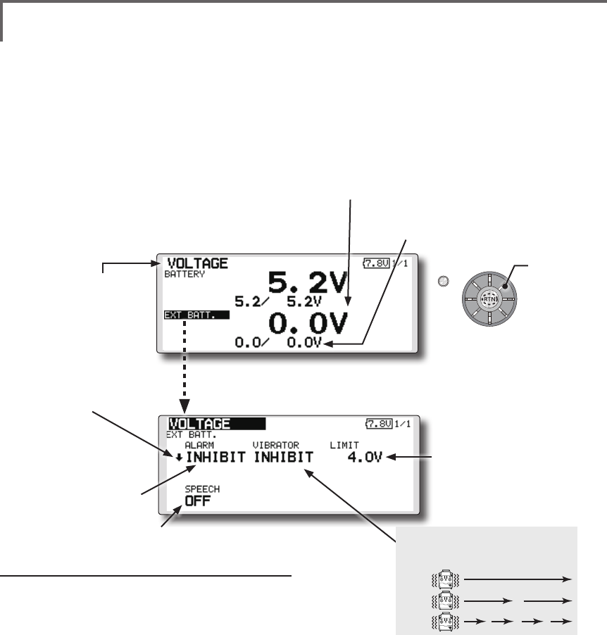
77
<Functions of Linkage Menu>
S1
<Edit dial>
● Select the function name
and return to the Linkage
menu by pushing the RTN
button or pushing the
Home/Exit button.
Alarm set
1. Move the cursor to the ↓ALARM item, and
it chooses from BUZZER, VOICE, and INHIBIT,
and pushes RTN.
2. When not operating vibrator, it is "VIBRATOR"
to INHIBIT. TYPE1-3 will be chosen if it is made
to operate.
3. Move the cursor to the LIMIT [4.0V] item and
push the RTN button to switch to the data
input mode.
4. Ajust the rate by scrolling the edit dial.
Initial value: 4.0V
Adjustment range: 0.0V~100.0V
*When the RTN button is pushed for one second, the rate is
reset to the initial value.
5. Push the RTN button. (To terminate the input
and return to the original state, push the
Home/Exit button.)
TELEMETRY : VOLTAGE [EXT-VOLT] Displaying data from the EXT
battery voltage port
In this screen, the EXT battery voltage is
displayed. In order to use this function, it is
necessary to connect External voltage connector of
FMR-03 ⇔ SBS-01V ⇔ Battery
SBS-01V measures two batteries. The power
battery connected to two lines is displayed on EXT-
VOLT.
*Only receiver voltage will be received in the FASSTest 12CH
mode.
*The FASSTest 18CH mode will display all telemetry data.
*SBS-01V must be installed in the aircraft.
● Select [VOLTAGE] in the TELEMETRY screen
and access the setup screen shown below by
pushing the RTN button.
● Select [EXT BATT.] in the RECEIVER screen
and access the setup screen shown
below by pushing the RTN button.
●A setup of the voltage on
which the alarm operates.
Scrolling
● Moving cursor
● EXT battery voltage ● The maximum and the minimum when
powering ON are shown. It will be preset,
if a cursor is moved to this place and the
RTN button is pushed for 1 second.
● ↓The "down" arrow will
indicate that an alarm will
sound when the voltage
drops to below the setting.
● ALARM is chosen from
BUZZER, VOICE, and
INHIBIT.
● The ON/OFF switch of SPEECH is chosen.
TYPE 1
TYPE 2
TYPE 3
"VIBRATOR" type
If the following types are selected, the
transmitter will vibrate during the warning.
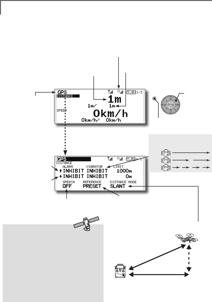
78 <Functions of Linkage Menu>
S1
<Edit dial>
● Select the function name
and return to the Linkage
menu by pushing the RTN
button or pushing the
Home/Exit button.
TELEMETRY : GPS [DISTANCE] Displaying data from the Distance Screen
The Distance screen displays and sets altitude
data from an SBS-01G GPS Sensor (sold
separately), and allows the distance to the airborne
aircraft to be read by the transmitter. When the
aircraft flies inside or outside the set distance an
alarm and vibration alerts the pilot.
*The GPS sensor is necessary, and is sold separately. Mount
and connect the sensor in accordance with the sensor
instruction manual.
*Only receiver voltage can be used in FASSTest 12CH mode.
*The FASSTest 18CH mode can use all the telemetry
functions.
*A GPS sensor must be installed in the aircraft.
●This indicates the receiving accuracy from a GPS
Satellite. When three bars are displayed, the GPS is
ready for use.
Surface
Altitude
Slant
●Altitude calculated as either straight line distance (slant)
or surface distance on a map can also be selected.
●Select <SLANT> <SURFACE> to “DISTANCE MODE”, scroll
either to the desired method and push the RTN button.
*Positioning time of GPS
When powered up, the SBS-01G begins to
acquire GPS satellite data. This process can
take several minutes. Please do not move the
model during this process. During acquisition,
the LED on the SBS-01G will blink green;
after the satellites signals have been acquired,
the LED will become solid green, and the GPS
signal strength display on the transmitter will
show three bars.
Moving the model before the satellites are fully
acquired will cause a delay in acquiring the
satellite signal.
● Select [GPS] in the TELEMETRY screen and
access the setup screen shown below by
pushing the RTN button.
Scrolling
● Moving cursor
● Distance
● ↓ A downward arrow
indicates the alarm will sound
when the distance reaches
below your set value.
● ↑ An upward arrow indicates
the alarm will sound when
the distance reaches above
your set value.
●Select [DISTANCE](small font display) in the
TEMPERATURE screen and access the setup
screen shown below by pushing the RTN
button.
● The maximum and the minimum when powering
ON are shown. It will be preset, if a cursor is
moved to this place and the RTN button is pushed
for 1 second.
●The ON/OFF switch of
SPEECH is chosen.
●Move the cursor to the [PRESET] of
"REFERENCE" item. Push the RTN button
is pushed for 1 second. Sets the current
aircraft position as the starting point.
TYPE 1
TYPE 2
TYPE 3
"VIBRATOR" type
If the following types are selected, the
transmitter will vibrate during the warning.
● Push the S1 button
to call next page.
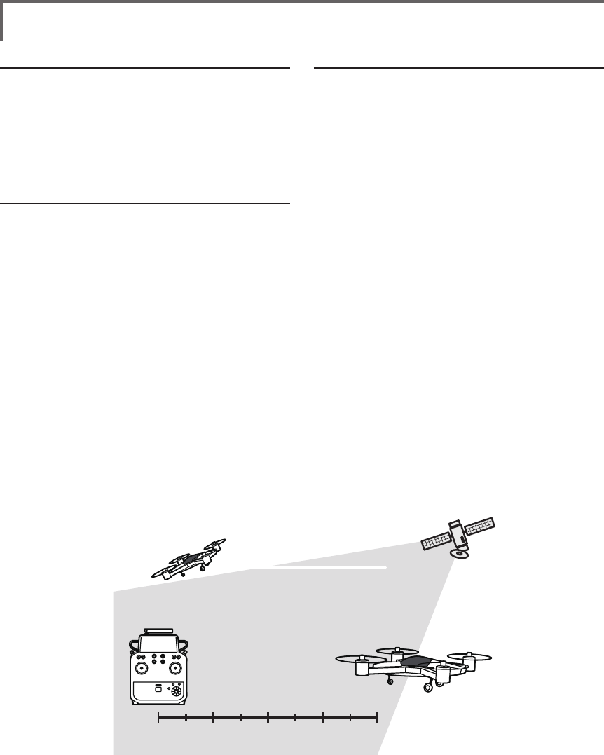
79
<Functions of Linkage Menu>
First, setting the pointos of reference is required.
1. The model and transmitter on which the GPS
sensor is connected are turned on.
2. Move the cursor to the [PRESET] of
"REFERENCE" item.
3. Push the RTN button is pushed for 1 second.
(To terminate the input and return to the original
state, push the Home/Exit button.)
*Now, the position of the present model was set to 0 m.
Setting a "too far" alarm distance
1. Move the cursor to the ↑ALARM item, and
it chooses from BUZZER, VOICE, INHIBIT, and
pushes RTN.
2. When not operating vibrator, it is "VIBRATOR"
to INHIBIT. TYPE1-3 will be chosen if it is made
to operate.
3. Move the cursor to the LIMIT [m] item and
push the RTN button to switch to the data
input mode.
4. Ajust the rate by scrolling the edit dial.
Initial value: 1,000m
Adjustment range 0m~3,000m
(↑LIMIT ≧ ↓LIMIT)
*When the RTN button is pushed for one second, the rate is
reset to the initial value.
5. Push the RTN button. (To terminate the input
and return to the original state, push the
Home/Exit button.)
Setting a "too close" alarm distance
1. Move the cursor to the ↓ALARM item, and
it chooses from BUZZER, VOICE, INHIBIT, and
pushes RTN.
2. When not operating vibrator, it is "VIBRATOR"
to INHIBIT. TYPE1-3 will be chosen if it is made
to operate.
3. Move the cursor to the LIMIT [m] item and
push the RTN button to switch to the data
input mode.
4. Ajust the rate by scrolling the edit dial.
Initial value: 0m
Adjustment range 0m~3,000m
(↑LIMIT ≧ ↓LIMIT)
*When the RTN button is pushed for one second, the rate is
reset to the initial value.
5. Push the RTN button. (To terminate the input
and return to the original state, push the
Home/Exit button.)
Distance
Speed
position
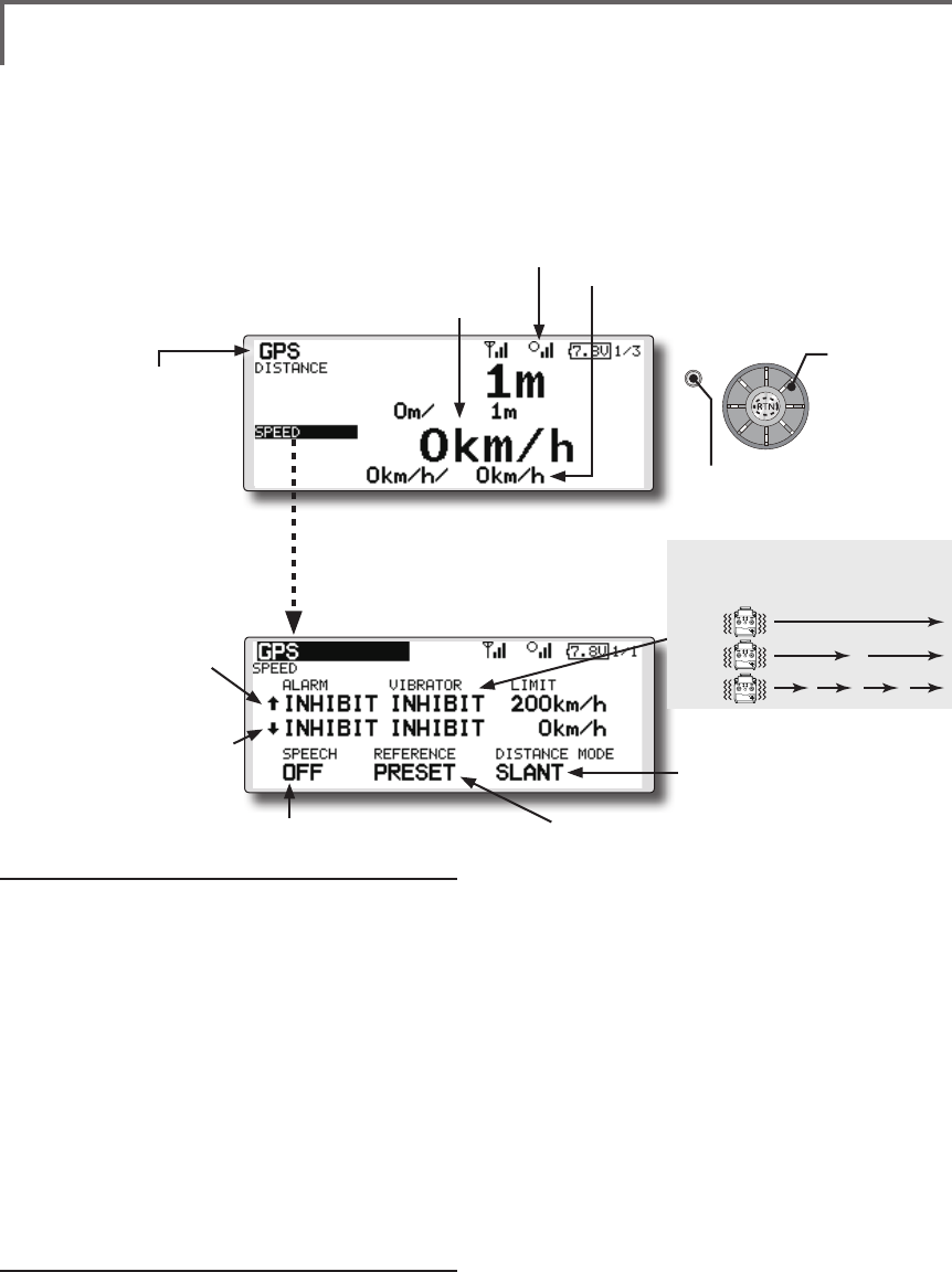
80 <Functions of Linkage Menu>
S1
<Edit dial>
● Select the function name
and return to the Linkage
menu by pushing the RTN
button or pushing the
Home/Exit button.
TELEMETRY : GPS [SPEED] Displaying data from the speed
The speed screen displays and sets the speed data from an
SBS-01G (GPS sensor) sold separately.
The speed of the aircraft during ight can be displayed.
After flight, the maximum speed during flight can be
viewed. Because this speed is based on position data from
a GPS satellite, the ground speed is displayed instead of
air speed. Consequently, with a head wind, the displayed
speed decreases and with a tail wind, the displayed speed
increases.
*The GPS sensor is necessary, and is sold separately. Mount and
connect the sensor in accordance with the sensor instruction manual.
*Only receiver voltage can be used in FASSTest 12CH mode.
*The FASSTest 18CH mode can use all the telemetry functions.
*A GPS sensor must be installed in the aircraft.
●This indicates the receiving accuracy from a
GPS Satellite. When three bars are displayed,
the GPS is ready for use.
● Select [GPS] in the TELEMETRY screen and
access the setup screen shown below by
pushing the RTN button.
Scrolling
● Moving cursor
● Speed
● ↓ A downward arrow
indicates the alarm will sound
when the speed reaches
below your set value.
● ↑ An upward arrow indicates
the alarm will sound when
the speed reaches above
your set value.
●Select [SPEED](small font display) in the
TEMPERATURE screen and access the setup
screen shown below by pushing the RTN
button.
● The maximum and the minimum when powering ON are
shown. It will be preset, if a cursor is moved to this place and
the RTN button is pushed for 1 second.
●The ON/OFF switch of
SPEECH is chosen.
●It links with the "DISTACE"
display.
●Pushing [PRESET] sets the current aircraft
position as the starting point.
Alarm setting when speed increases
1. Move the cursor to the ↑ALARM item, and it
chooses from BUZZER, VOICE, INHIBIT, and pushes
RTN.
2. When not operating vibrator, it is "VIBRATOR"
to INHIBIT. TYPE1-3 will be chosen if it is made to
operate.
3. Move the cursor to the LIMIT [km/h] item and push
the RTN button to switch to the data input mode.
4. Ajust the rate by scrolling the edit dial.
Initial value: 200km/h
Adjustment range 0km/h-500km/h
(↑LIMIT ≧ ↓LIMIT)
*When the RTN button is pushed for one second, the rate is
reset to the initial value.
5. Push the RTN button. (To terminate the input and
return to the original state, push the Home/Exit
button.)
Alarm setting when speed decreases
1. Move the cursor to the ↓ALARM item, and it
chooses from BUZZER, VOICE, INHIBIT, and pushes
RTN.
2. When not operating vibrator, it is "VIBRATOR"
to INHIBIT. TYPE1-3 will be chosen if it is made to
operate.
3. Move the cursor to the LIMIT [km/h] item and push
the RTN button to switch to the data input mode.
4. Ajust the rate by scrolling the edit dial.
Initial value: 0km/h
Adjustment range 0km/h-500km/h
(↑LIMIT ≧ ↓LIMIT)
*When the RTN button is pushed for one second, the rate is
reset to the initial value.
5. Push the RTN button. (To terminate the input and
return to the original state, push the Home/Exit
button.)
*Speed alarm precaution
Since the GPS speed sensor displays the ground speed, it
cannot be used as a stall alarm. For example, an aircraft that
stalls at 50km/h will stall if the tailwind is 5km/h or greater
even through 55km/h is displayed by ground speed. In
addition, with an aircraft that will fail in midight at 400km/
h at an over-speed alarm, when the headwind reaches 30km/h
the airplane will fail in midair due to over speeding even at a
ground speed of 370km/h.
TYPE 1
TYPE 2
TYPE 3
"VIBRATOR" type
If the following types are selected, the
transmitter will vibrate during the warning.
● Push the S1 button
to call next page.